67
The Fitting Authority Equipment

The Fitting Authority
Equipment

Parker Hannifin CorporationTube Fittings DivisionColumbus, Ohiowww.parker.com/tfd
S2
4300 Catalog Equipment
Braze Flux
S22
Post Braze Cleaner
S22
Multi-Flame Torch
S22
Benders
Hand Tube Benders
S4 – S5
Ratchet Hand TubeBender
S4
BVP06/181Tube Bending Tool
S6
1" Hand Tube Bender
S5
BAV06/12Combined Tube Bending& Cutting Tool
S5
BV06/18, BV20/25Tube Bending Tools
S6
Exactol Benders412 & 424
S8 – S11
HB632Hydraulic Bender
S12 – S16
Mandrel BendingComponents
S16 – S18
CP432 Tube and PipeBender Kit
S19
BrazingEquipment
KloskutMedium (Sizes 2 to 18)
S23
Cutting &DeburringTools
KloskutLarge (Sizes 12 to 32)
S23
In-ExDeburring Tool(Sizes 2-26)
S24
Cut-Off Saw974250
S23
Tru-KutSawing Vise (Sizes 3-32)
S23
Power Deburr Tool
S24
FlangingTools
Parflange 1090
S25
Parflange 1025
S28
Flanging Pin and DieSets
S29
Parflange 1040
S27
Parflange 1009
S26
FlaringTools
210ACombination Tool(Sizes 2 to 10)
S30
1015-1Hydraulic FlaringMachine
S36
Vise Block andFlaring Pin(Sizes 4 to 24 and6-38mm)
S30 - S31
Rolo-FlairRotary, Manual(Sizes 2 to 12)
S32
Hydra-ToolHydraulic Flaring &Pre-Setting Tool
S33 – S35
Flaring Tooling forParflange
S37
PortingTools
ISO 6149-1Port Counterbore
S41
ISO 6149-1Port Counterbore with IDGroove
S41
Straight ThreadPort Tap(Sizes 2 to 32)
S38
SAE Straight ThreadPort Counterbore(Sizes 2 to 32)
S38
BSPP/BSPT Taps
S39
BSPP Counterbores
S39
Pre-SettingTools
FerulsetFerrule Pre-Setter(Sizes 2 to 32)
S42
Bender CapacityGuides
S7
ISO 6149-1Port Tap
S40
NPT Taps
S40

Parker Hannifin CorporationTube Fittings DivisionColumbus, Ohiowww.parker.com/tfd
S3
4300 Catalog Equipment
VOMOPre-AssemblyBodies
S43
KONUCone Gauges
S44
Hyferset FerrulePre-Setter(Sizes 4 to 32)
S45 – S47
Pre-Setting Toolingfor Hydra-Tool
S48 – S49
EO-Karrymat
S51 - S52
HVMBPre-Assembly Tool
S50
EOMAT III
S53
O-Ring Pick
S54
O-RingAssemblyTools
Captive O-RingInstallation Tool
S54
O-RingInstallation Kit
S54
SafetyEyewear &Accesso-ries
Sealants,Lubricants,& Cleaners
PTFE Tape
S59
LB 2000 & MPG-2
S56
Loctite Anti-SeizeLubricant
S56
Loctite ThreadSealant 567
S58
Loctite ThreadSealant 545
S58
Loctite Threadlocker242
S59
Loctite Threadlocker271
S60
Loctite 7649Primer N
S59
EO Lubricants
S56
STP
S56
Threadmate
S58
Modular PreparationCenters
S62
TubePreparationCenters
ThreadIdentification
ThreadIdentification Kit
S63
Portboards
S63
ITKInternational Thread Kit
S63
Wrenches
Par-Lok Wrenches
S64 – S65
Safety Glasses
S55
Lens Cleaners
S55
Displays
S55
Super-Lube PTFEGrease
S57
Loctite PenetratingOil
S57
O-Lube
S57
Super O-Lube
S57
Loctite Fast OrangeHand Cleaner
S60
Pipe Sealing Cord
S59
Loctite Natural BlueDegreaser
S60
Loctite Rack
S61
Loctite Parts Cleaner
S61
Weights
Tube FabricatingEquipment WeightChart
S66 – S67

Parker Hannifin CorporationTube Fittings DivisionColumbus, Ohiowww.parker.com/tfd
S4
4300 Catalog Equipment
Hand Tube Benders – InchThese are sturdy, easy-to-use hand tools for fast and accu-rate bending without kinks or visible flattening. Twelve indi-vidual sizes from -2 (1/8" O.D.) to -16 (1" O.D.) are available.
Medium Duty Inch Hand Tube Benders
Designed and built for fast, accurate bends and long servicelife.
These are individual benders for eight inch tube sizes (1/8",3/16", 1/4", 5/16", 3/8", 1/2" 5/8", 3/4"). All of these benders willbend copper, aluminum, annealed steel and stainless steel.These can be used in hands or mounted in a bench vise.
HOW TO USE: Simply align marks on slide block and radiusblock, then bend to the desired angle (up to 180°) by pullingsteadily on the slide block handle. Bend angles are indicatedon the radius block, both front and back. (Detailed instructionsare included with each bender.) See the table below fortechnical data and part numbers.
RecommendedRadius to Min. Wall Max. Wall Thickness
Tube Tube Without Copper, Steel,O.D. Centerline Flattening Aluminum Stainless Steel
Size (in.) (in.) (in.) (in.) (in.) Part No.
2 1/8 7/16 0.012 Any 0.032 ........ 2-2829S3 3/16 9/16 0.020 Any 0.032 ........ 3-2829S4 1/4 9/16 0.028 Any 0.083 ........ 4-2829S5 5/16 15/16 0.032 Any 0.083 ........ 5-2829S6 3/8 15/16 0.032 Any 0.083 ........ 6-2829S8 1/2 1 1/2 0.042 Any 0.083 ........ 8-2829S
Ratchet Hand Tube Benders
These are individual benders for three tube sizes, 5/8", 3/4"and 7/8", in copper, aluminum, annealed steel and stainlesssteel. They can be used in hands or mounted in a bench vise.
HOW TO USE: Position the tube in the bender, close the latchand pull the ratchet handle away from radius block handleuntil the desired angle (up to 180°) is formed. Bend angles areindicated on the radius block. (Detailed instructions are in-cluded with each bender.) See the table below for technicaldata and part numbers.
RecommendedRadius to Min. Wall Max. Wall Thickness
Tube Tube Without Copper, Steel,O.D. Centerline Flattening Aluminum Stainless Steel
Size (in.) (in.) (in.) (in.) (in.) Part No.
10 5/8 3 0.042 Any 0.049 ........ 10-282912 3/4 3 3/4 0.049 Any 0.065 ........ 12-282914 7/8 3 3/4 0.049 Any 0.065 ........ 14-2829
Fig. S1 — Medium Duty InchHand Tube Bender
Fig. S2 — Ratchet Hand TubeBender
Benders

Parker Hannifin CorporationTube Fittings DivisionColumbus, Ohiowww.parker.com/tfd
S5
4300 Catalog Equipment
Fig. S3 — 1" Hand Tube Bender
1" Hand Tube BenderPart No. 16-2829
For 1" O.D. tube in soft copper and aluminum materials. Thisbender can be used in hands, but mounting in a bench vise issuggested, especially for heavier wall thickness tube.
HOW TO USE: Align marks and bend the tube to the desiredangle (up to 180°) by pulling steadily on the operating handle.The handle may be re-positioned for maximum leverage.Bend angles are indicated on the radius block. (Detailedinstructions are included with the bender.) See the tablebelow for technical data and part numbers.
RecommendedRadius to Min. Wall Max. Wall Thickness
Tube Tube Without Copper, Steel,O.D. Centerline Flattening Aluminum Stainless Steel
Size (in.) (in.) (in.) (in.) (in.) Part No.
16 1 3 1/2 0.065 Any Not ............ 16-2829Recommended
Hand Tube Benders – MetricThese are sturdy, easy-to-use hand tools for fast and accu-rate bending without kinks or visible flattening. Individualsizes in ten models from size 5mm to 25mm are available.
Medium Duty Metric Hand Tube Benders
Designed and built for fast, accurate bends and long servicelife.
These are individual benders for six metric tube sizes (5mm,6mm, 8mm, 10mm, 12mm and 14mm). All of these benderswill bend copper, aluminum, annealed steel and stainlesssteel. These can be used in hands or mounted in a bench vise.
HOW TO USE: Simply align the marks on the slide block andradius block, then bend to the desired angle (up to 180°) bypulling steadily on the slide block handle. Bend angles areindicated on the radius block, both front and back. (Detailedinstructions are included with each bender.) See the tablebelow for technical data and part numbers.
RecommendedRadius to Min. Tube Max. Wall Thickness
Tube Tube Wall Copper, Steel,O.D. Centerline Thickness Aluminum Stainless Steel(mm) (mm) (mm) (mm) (mm) Part No.
5 14.3 0.5 Any 1.0 ......... 2-2829S6 14.3 1.0 Any 1.5 ......... 3-2829S8 23.8 1.0 Any 1.5 ......... 4-2829S
10 23.8 1.0 Any 2.0 ......... 5-2829S12 38.1 1.0 Any 2.0 ......... 6-2829S14 38.1 1.0 Any 2.0 ......... 8-2829S
Bench Mount Metric Hand Bender andCutting Guide
This bender combines a tube cutting guide with the bender forsizes 6mm, 8mm, 10mm, and 12mm. There are three benderrollers that cover all sizes. The bender mounts easily to a workbench or table.
Part Description Part No.Bench Mount Tube Bender (6mm, 8mm, 10mm, 12mm) .......... BAV06/12KPLX
Fig. S4 — Medium Duty MetricHand Tube Bender
Fig. S5 — BAV06/12KPLX
Benders

Parker Hannifin CorporationTube Fittings DivisionColumbus, Ohiowww.parker.com/tfd
S6
4300 Catalog Equipment
Fig. S6 — BV06/18KPLX
Vise Mount Metric Hand BendersVise Mount Metric Bender – 6/18mm
This bender has six interchangeable rollers to cover tubesizes 6mm, 8mm, 10mm, 12mm, 14mm, 15mm, 16mm, and18mm.
Part Description Part No.Vise Mount Tube Bender(6mm, 8mm, 10mm, 12mm, 14mm, 15mm, 16mm, 18mm) ...... BAV06/18KPLX
Vise Mount Metric Bender – 20/25mm
This bender has three interchangeable rollers to cover tubesizes 20mm, 22mm, and 25mm. All bend radii are 86.5mm.Pressure arm is not included with the BV20/25KPLX, how-ever it can be manufactured on site with a piece of tube, or itcan be ordered separately with part number BV20/2510X.Maximum wall thickness for all sizes is 2.0mm.
Part Description Part No.Vise Mount Tube Bender (20mm, 22mm, 25mm) ..................... BAV20/25KPLXPressure Arm ............................................................................. BV20/2510X
Programmable Vise MountMetric Bender – 6/18mm
This bender has 6 interchangeable rollers which cover tubesizes 6mm, 8mm, 10mm, 12mm, 14mm, 15mm, 16mm, and18mm. Also standard with the bender is the program rail,guide rail and dimension rail in either one or two meterlengths. The BVP can be manually programmed to offerrepeatability of bends. For bend radii and maximum wallthichness, see BV06/18KPLX.
Part Description Part No.Programmable Vise Mount Tube Bender(6mm, 8mm, 10mm, 12mm, 14mm, 15mm, 16mm, 18mm) ...... BVP06/181
Fig. S7 — BV20/25KPLX
Fig. S8 — BVP 06/181
6 33 2.58 34 2.510 36 2.512 37 2.514 37 2.015 44 2.016 44 2.018 52 2.0
Tube O.D.(mm)
Bend Radius(mm)
Max. WallThickness
(mm)
Benders

Parker Hannifin CorporationTube Fittings DivisionColumbus, Ohiowww.parker.com/tfd
S7
4300 Catalog Equipment
Hand Crank & Hydraulic TubeBender Capacity GuidesAll benders listed in Tables S1 through S3 are capable ofbending 1/2" O.D. and under fully annealed steel and stain-less steel tube with no limit on wall thickness. For HARDcopper and HIGH STRENGTH aluminum, use the wall thick-ness shown for stainless steel. Observe that VERY HARDmaterials may not be ductile enough to bend without fracture.
Inch Tube Sizes
Table S1 — Hand Crank and Hydraulic Tube Benders Maximum Capacity Guide – Inch Sizes
Table S3 — Hand Crank and Hydraulic Tube Benders Maximum Capacity Guide –Metric Tube Sizes
Table S2 — Hand Crank and HydraulicBenders Maximum Capacity Guide – InchPipe Sizes
*Codes:(A) Model 412 — Tube (1/4" thru 3/4" and 6mm thru 20mm) — Worm & Gear(B) Model 424 — Tube (1/4" thru 1 1/2" and 6mm thru 38mm) — Worm & Gear(C) Model HB632 — Tubeg (3/8" thru 2" and 10mm thru 50mm) — Hydraulic(D) Model CP432 — Tube (1/4" thru 2") — Hydraulic
Metric Tube SizesInch Pipe Sizes
Tube Wall Thickness (in.)
Tube 0.035 0.049 0.058 0.065 0.072 0.083 0.095 0.109 0.120 0.134 0.156 0.188O.D. Material Bender Code*3/4" S ABCD ABCD ABCD ABCD BCD BCD BCD BCD BCD BCD BCD BCD
SS BCD BCD BCD BCD BCD BCD BCD BCD BCD BCD BCD BCD1" S BCD BCD BCD BCD BCD BCD BCD BCD BCD BCD BCD BCD
SS BCD BCD BCD BCD BCD BCD BCD BCD BCD BCD CD CD1 1/4" S BCD BCD BCD BCD BCD BCD CD CD CD CD CD CD
SS BCD BCD BCD BCD BCD CD CD CD CD CD C C1 1/2" S BCD BCD BCD BCD BCD CD CD CD CD CD CD CD
SS BCD BCD CD CD CD CD CD CD CD CD C C2" S CD CD CD CD CD CD CD CD CD CD CD CD
SS CD CD CD CD CD CD CD CD CD CD — —
Tube Tube Wall Thickness (mm)
O.D. 1.5 2 2.5 3 3.5 4 5(mm) Material Bender Code*
18 S ABCD ABCD ABCD ABCD BCD BCD CDSS BCD BCD BCD BCD BCD BCD CD
20 S ABCD ABCD ABCD BCD BCD BCD CDSS BCD BCD BCD BCD BCD BCD CD
22 S BCD BCD BCD BCD BCD BCD CDSS BCD BCD BCD BCD BCD CD CD
25 S BCD BCD BCD BCD BCD CD CDSS BCD BCD BCD BCD CD CD CD
28 S BCD BCD BCD BCD CD CD CDSS BCD BCD CD CD CD CD CD
30 S BCD BCD BCD BCD CD CD CDSS BCD BCD CD CD CD CD CD
32 S BCD BCD CD CD CD CD CDSS BCD BCD CD CD CD CD CD
35 S BCD CD CD CD CD CD CDSS BCD CD CD CD CD CD CD
38 S BCD CD CD CD CD CD CDSS CD CD CD CD CD CD CD
42 S CD CD CD CD CD CD CDSS CD CD CD CD CD CD —
50 S CD CD CD CD CD CD —SS CD CD CD CD CD — —
Pipe 40 80Size Material1/2" S CD CD
SS CD CD3/4" S CD CD
SS CD CD1" S CD CD
SS CD CD1 1/4" S CD CD
SS CD CD1 1/2" S CD CD
SS CD CD2" S D D
SS D —
Bender Code*
Inch Pipe Schedule(IPS)
Benders

Parker Hannifin CorporationTube Fittings DivisionColumbus, Ohiowww.parker.com/tfd
S8
4300 Catalog Equipment
Exactol® Crank-Operated BendersModels 412/424
These portable benders are vise or bench mountable for easyaction and fast accurate bending to 180°. Two models areavailable to bend tube sizes 4 (1/4") through 24 (1 1/2").Exactol benders are designed with a worm-gear drive with a60 to 1 gear ratio to allow accurate bending with minimumeffort. They bend aluminum, copper, annealed steel andannealed stainless steel without kinks or wrinkles. Easy crankoperation permits continuous production without excessiveoperator fatigue; for use in tube fabrication shops, in the field,or in factory maintenance departments.
A VHS video is included to provide proper instructions for use.
Exactol® Model 412The Exactol Model 412 will bend tube from size 4 (1/4")through size 12 (3/4") and 6mm through 20mm inclusive andis completely portable. Accessories include a sturdy metalcarrying case, which accommodates the 412 bender, slideblock, and selected radius blocks. See page S7 for wallthickness capabilities. May be held in a vise or bench mountedusing the bench mounting adapter. Bulletin 4391-B400S andvideo are included with bender, which describe the operationin detail.
NOTE: The 412 must be bench mounted if mandrels are used.
COMPONENTS REQUIREDThe minimum components required are a Model 412 Benderwith a slide block and a radius block which match the tubeO.D. to be bent.
Part Name Part No.Exactol Model 412 Bender (for 1/4" through 3/4" O.D.) ............ 560569Slide Block (for sizes 4-5-6-8-10-12) ......................................... 550585Slide Block (for sizes 6mm-8mm-12mm-12mm-14mm) ............ 820091Slide Block (for sizes 15mm-16mm-18mm-20mm) ................... 820092Radius Blocks (for sizes 4-5-6-8-10-12 and 6mm thru 38mm) ... See pages S10 – S11
OPTIONAL ACCESSORIESCarrying Case
(for bender, slide block and selected radius blocks) .......... 550572Bench Mounting Adapter ........................................................... 550570Operation Video ......................................................................... 4390-TFV
Mandrel Bending Componentsfor 412 and 424 Benders ............................................................ See pages S16 – S18
Fig. S9 — 412 Bender
Fig. S10 — Slide Block
Fig. S11 — Bench MountAdapter
Benders

Parker Hannifin CorporationTube Fittings DivisionColumbus, Ohiowww.parker.com/tfd
S9
4300 Catalog Equipment
Fig. S13 — 424 Bender
Fig. S14 — Slide Block
Fig. S15 — Bench MountAdapter
Exactol® Model 412 KitThis 412 kit contains all the basic tool requirements forbending tube from 1/4" through 3/4".
Part No.412 KIT
The following part numbers are included in the kit:
Part Name Part No.Exactol Model 412 Bender ........................................................ 560569Carrying Case ............................................................................ 550572Slide Block for 1/4" through 3/4" tube ........................................ 550585Radius Block – 1/4" O.D. tube ................................................... 550579Radius Block – 3/8" O.D. tube ................................................... 550581Radius Block – 1/2" O.D. tube ................................................... 550582Radius Block – 5/8" O.D. tube ................................................... 550583Radius Block – 3/4" O.D. tube ................................................... 550584
Exactol® Model 424The Exactol Model 424 will bend tube from size 4 (1/4" O.D.)through size 24 (1 1/2" O.D.) and 6mm through 38mm inclu-sive. See page S7 for wall thickness capabilities. It is com-pletely portable and may be vise or bench mounted. Bulletin4391-B400S and video are included with the bender, whichdescribe the operation in detail.
NOTE: The 424 must be bench mounted if mandrels areused.
A VHS video is included to provide proper instructions for use.
COMPONENTS REQUIREDThe minimum components required are a Model 424 Benderwith a slide block and a radius block that match the tube O.D.to be bent.
Part Name Part No.Exactol Model 424 bender (for 1/4" through 1 1/2" O.D.) ......... 621044Slide Block (for sizes 4-5-6-8-10-12) ......................................... 550585Slide Block (for size 24) ............................................................. 870150Slide Block (for sizes 14-16-18-20) ........................................... 621045Slide Block (for sizes 6mm-8mm-10mm-12mm-14mm) ............ 820091Slide Block (for sizes 15mm-16mm-18mm-20mm) ................... 820092Slide Block (for sizes 22mm-25mm-28mm-30mm) ................... 820093Slide Block (for size 38mm) ....................................................... 870150Radius Blocks (for sizes -4 thru -24 and 6mm thru 38mm) ........ See pages S10 – S11
OPTIONAL ACCESSORIESBench Mounting Adapter ........................................................... 631156Mandrel Bending Components
for 412 and 424 Benders ........................................................ See pages S16 – S18Operation Video ......................................................................... 4390-TFV
Fig. S12 — 412 Kit
Benders

Parker Hannifin CorporationTube Fittings DivisionColumbus, Ohiowww.parker.com/tfd
S10
4300 Catalog Equipment
Fig. S16 — 424 Kit
Exactol® Model 424 KitPart No. 424 Kit
This 424 Kit contains all the basic tool requirements forbending tube from 1/4" through 1 1/2". The following partnumbers are included in the kit:
Part Name Part No.Exactol Model 424 bender (for 1/4" through 1 1/2" O.D.) ......... 621044Slide Block (for sizes 4-5-6-8-10-12) ......................................... 550585Slide Block (for sizes 14-16-18-20) ........................................... 621045Slide Block (for size 24)* ........................................................... 870150Radius Blocks – 1/4" O.D. Tube* .............................................. 550579Radius Block – 3/8" O.D. Tube .................................................. 550581Radius Block – 1/2" O.D. Tube .................................................. 550582Radius Block – 5/8" O.D. Tube .................................................. 550583Radius Block – 3/4" O.D. Tube .................................................. 550584Radius Block – 1" O.D. Tube ..................................................... 621047Radius Block – 1 1/4" O.D. Tube ............................................... 621049Radius Block – 1 1/2" O.D. Tube* ............................................. 870149
* Items not shown in the photo, but which are included in the424 Kit.
Radius BlocksFor use with Exactol Models 412/424 benders.
The 412 and 424 bender radius blocks have built in tubeclamps, therefore separate clamp blocks are not required.The radius blocks are interchangeable within bender sizeranges. Close bend radius blocks utilize the small bend radii,but also allow the bend to begin closer to the end connection.
412 and 424 Bender – Small Radius Blocks
Tube BendO.D. Radius
Size (in.) (in.) Part No.
4 1/4 9/16 ............................................................ 5505735 5/16 11/16........................................................... 5505746 3/8 15/16........................................................... 5505758 1/2 1 1/4 ........................................................... 550576
10 5/8 1 1/2 ........................................................... 55057712 3/4 1 3/4 ........................................................... 550578
412 and 424 Bender – Large Radius Blocks
Tube BendO.D. Radius
Size (in.) (in.) Part No.
4 1/4 3/4 ............................................................. 5505795 5/16 1 .............................................................. 5505806 3/8 1 1/4 ........................................................... 5505818 1/2 2 .............................................................. 550582
10 5/8 2 1/2 ........................................................... 55058312 3/4 3 .............................................................. 55058414 7/8 3 1/2 ........................................................... 62104616 1 4 .............................................................. 62104718 1 1/8 4 1/2 ........................................................... 62104820 1 1/4 5 .............................................................. 62104924 1 1/2 5 .............................................................. 870149
Benders

Parker Hannifin CorporationTube Fittings DivisionColumbus, Ohiowww.parker.com/tfd
S11
4300 Catalog Equipment
Fig. S17 — Close Bend RadiusBlock
Fig. S19 — Seal-Lok Close BendAdapter
412 and 424 Bender – Close Bend Radius Blocks
Tube BendO.D. Radius
Size (in.) (in.) Part No.
8 1/2 1 1/4 ........................................................... 59053310 5/8 1 1/2 ........................................................... 59053512 3/4 1 3/4 ........................................................... 590537
412 and 424 Bender – Metric Radius Blocks
Tube BendO.D. Radius(mm) (mm) Part No.
6 14 ........................................................................... 820090-6mm8 18 ........................................................................... 820090-8mm
10 24 ........................................................................... 820090-10mm12 32 ........................................................................... 820090-12mm14 38 ........................................................................... 820090-14mm15 38 ........................................................................... 820090-15mm16 38 ........................................................................... 820090-16mm18 44 ........................................................................... 820090-18mm20 44 ........................................................................... 820090-20mm22 89 ........................................................................... 820090-22mm25 102 .......................................................................... 820090-25mm28 102 .......................................................................... 820090-28mm30 127 .......................................................................... 820090-30mm38 127 .......................................................................... 820090-38mm
Close Bend Adapters for Seal-Lok
These adapters are used when bends are needed close to theend of the tube after the flange has been made or the sleevehas been brazed onto the end of the tube.
HOW TO USE: Screw the Seal-Lok adapter into the internalthread* of the threaded pin on the radius block. Then attachthe flanged or brazed tube by threading the tube nut to theSeal-Lok adapter on the radius block threaded pin.* If the threaded pin does not have an internal thread, a new threaded pin is required.
Tube O.D.(in.) Description Part No.
1/2 Seal-Lok Adapter .............................................. 930421-85/8 Seal-Lok Adapter .............................................. 930421-103/4 Seal-Lok Adapter .............................................. 930421-121 Seal-Lok Adapter .............................................. 930421-16
1 1/4 Seal-Lok Adapter .............................................. 930421-201 1/2 Seal-Lok Adapter .............................................. 930421-241/2 Threaded Pin (for Close Bend Radius Blocks) 930420-85/8 Threaded Pin (for Close Bend Radius Blocks) 930420-103/4 Threaded Pin (for Close Bend Radius Blocks) 930420-121 Threaded Pin (for Close Bend Radius Blocks) 930420-16
1 1/4 Threaded Pin (for Close Bend Radius Blocks) 930420-201 1/2 Threaded Pin (for Close Bend Radius Blocks) 930420-24
Fig. S18 — Radius Block
Benders

Parker Hannifin CorporationTube Fittings DivisionColumbus, Ohiowww.parker.com/tfd
S12
4300 Catalog Equipment
Hydraulic Tube BenderModel HB632Hydraulic power does the work in bending tube of all materialsin sizes from 6 (3/8" O.D.) through size 32 (2" O.D.), 10mmthrough 50mm, with wall thicknesses as great as .188 forannealed steel, and pipe sizes from 3/8" through 1-1/2". Seepage S7 for wall thickness capabilities. The radius block,around which the tube is bent, is driven by a roller chain andsprocket powered by a cylinder and a separate hydraulicpower unit.
Maximum bend angle is 180° with radii from 1 1/4" to 8". Closesecond bends can be performed in either direction. An adjust-able stop controls the degree of bend to a maximum of 180°and is graduated in 1° increments. After the bend is com-pleted and pressure is released, a spring returns the clamparm to the zero starting position.
The clamp vise arm features a quick release speed screw forpositioning the required clamp block. Each size of tube re-quires the proper sized radius block, clamp block and slideblock.
Written instructions, a VHS video and Bulletin 4391-B26 areincluded with each bender.
HB632 radius blocks, slide blocks and clamp blocks will workwith the following benders as well: 624, 824, 832 and 848.
NOTE: For size 28 (1 3/4" O.D. tube) through 32 (2" O.D. tube)radius blocks, an adapter plate is required.
DIMENSIONS: L – 40" W – 11" H – 12"
COMPONENTS REQUIREDMinimum components required are a Model HB632 Bender,hose assembly, hydraulic pump and a radius, slide and clampblock which match the tube/pipe O.D. to be bent.
Part Name Part No.Hydraulic Bender Model HB632 (without pump) ....................... 631050Hydraulic Pump (10,000 psi, 110V AC) .................................... 900085High Flow Hydraulic Pump (10,000 psi, 110V) ......................... 974691Hose Assembly (3' long) ............................................................ 910004
One each of the following is required per tube O.D.:Radius Block, Clamp Block, Slide Block.Radius Block .............................................................................. See pages S13 – S15
INCH TUBE SIZESClamp Block (for -6) ................................................................... 864266Clamp Block (for -8, -12, -16, -24) ............................................. 631092Clamp Block (for -10, -14, -18, -20) ........................................... 631093Clamp Block (for -28) ................................................................. 027418-28Clamp Block (for -32) ................................................................. 027418-32Slide Block (for -6) ..................................................................... 864276Slide Block (for -8, -12, -16, -24) ............................................... 520516Slide Block (for -10, -14, -18, -20) ............................................. 520518Slide Block (for -28) ................................................................... 631063Slide Block (for -32) ................................................................... 631066
Fig. S20 — HB632
Fig. S21 — 900085 Pump
Fig. S23 — Clamp Block
Fig. S22 — High FlowPump
Fig. S24 — Slide Block
Benders

Parker Hannifin CorporationTube Fittings DivisionColumbus, Ohiowww.parker.com/tfd
S13
4300 Catalog Equipment
Fig. S26 — Radius Block for usewith HB632 Bender
METRIC TUBE SIZESClamp Block (for 10mm, 12mm, 14mm, 16mm) ........................ 790017Clamp Block (for 15mm, 16mm, 18mm, 20mm) ........................ 780195Clamp Block (for 22mm, 25mm, 30mm, 32mm) ........................ 780196Clamp Block (for 35mm) ............................................................ 974346Clamp Block (for 38mm) ............................................................ 631092Clamp Block (for 42mm) ............................................................ 974349Clamp Block (for 50mm) ............................................................ 974352Slide Block (for 10mm, 12mm, 14mm, 16mm) .......................... 790016Slide Block (for 15mm, 16mm, 18mm, 20mm) .......................... 780192Slide Block (for 22mm, 25mm, 30mm, 32mm) .......................... 780193Slide Block (for 35mm) .............................................................. 974345Slide Block (for 38mm) .............................................................. 520516Slide Block (for 42mm) .............................................................. 974348Slide Block (for 50mm) .............................................................. 974351
INCH PIPE SIZESClamp Block (for 3/8", 1/2", 3/4") ............................................... 974332Clamp Block (for 1") ................................................................... 974338Clamp Block (for 1 1/4") ............................................................. 974341Clamp Block (for 1 1/2") ............................................................. 974343Slide Block (for 3/8", 1/2", 3/4") ................................................. 974331Slide Block (for 1") ..................................................................... 974336Slide Block (for 1 1/4") ............................................................... 974340Slide Block (for 1 1/2") ............................................................... 974342
OPTIONAL ACCESSORIESRadius Block Adapter Plate
(for sizes 1 1/2", 38mm, 1 1/4 IPS and larger) ................... 660221Mandrel Bending Components for HB632 .................................. See pages S16 – S18Operation Video ......................................................................... 4390-TFV
Radius Blocks
For use with HB632 Bender
Radius blocks for every standard tube size from size 6 (3/8"O.D.) to size 32 (2" O.D.), 10mm through 50mm, and inch pipesizes 3/8" through 1-1/2" are available.
AND10111 Standard Radius Blocks – Inch Sizes
Tube O.D. RadiusSize (in.) (in.) Part No.
6 3/8 1 1/4 ........................................................... 5405028 1/2 1 1/4 ........................................................... 530763
10 5/8 1 1/2 ........................................................... 53076412 3/4 1 3/4 ........................................................... 53076514 7/8 2 .............................................................. 53076618 1 1/8 3 1/2 ........................................................... 53076824 1 1/2 5 .............................................................. 530770*28 1 3/4 7 .............................................................. 631057-112*32 2 8 .............................................................. 631060-128** Requires the use of Radius Block Adapter Plate, Part No. 660221.
Fig. S25 — Radius Block AdapterPlate
Benders
Parker Hannifin CorporationTube Fittings DivisionColumbus, Ohiowww.parker.com/tfd
S14
4300 Catalog Equipment
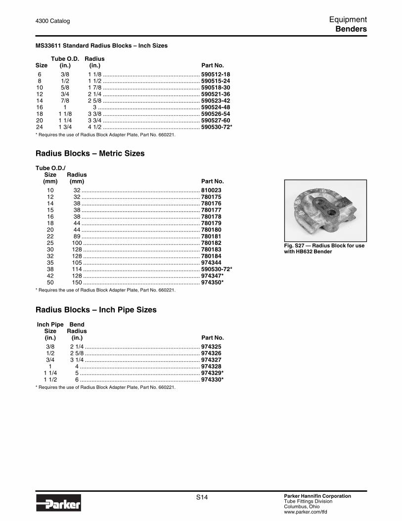
MS33611 Standard Radius Blocks – Inch Sizes
Tube O.D. RadiusSize (in.) (in.) Part No.
6 3/8 1 1/8 ........................................................... 590512-188 1/2 1 1/2 ........................................................... 590515-24
10 5/8 1 7/8 ........................................................... 590518-3012 3/4 2 1/4 ........................................................... 590521-3614 7/8 2 5/8 ........................................................... 590523-4216 1 3 .............................................................. 590524-4818 1 1/8 3 3/8 ........................................................... 590526-5420 1 1/4 3 3/4 ........................................................... 590527-6024 1 3/4 4 1/2 ........................................................... 590530-72** Requires the use of Radius Block Adapter Plate, Part No. 660221.
Radius Blocks – Metric Sizes
Tube O.D./Size Radius(mm) (mm) Part No.
10 32 ........................................................................ 81002312 32 ........................................................................ 78017514 38 ........................................................................ 78017615 38 ........................................................................ 78017716 38 ........................................................................ 78017818 44 ........................................................................ 78017920 44 ........................................................................ 78018022 89 ........................................................................ 78018125 100 ....................................................................... 78018230 128 ....................................................................... 78018332 128 ....................................................................... 78018435 105 ....................................................................... 97434438 114 ....................................................................... 590530-72*42 128 ....................................................................... 974347*50 150 ....................................................................... 974350*
* Requires the use of Radius Block Adapter Plate, Part No. 660221.
Radius Blocks – Inch Pipe Sizes
Inch Pipe BendSize Radius(in.) (in.) Part No.
3/8 2 1/4 ...................................................................... 9743251/2 2 5/8 ...................................................................... 9743263/4 3 1/4 ...................................................................... 9743271 4 ......................................................................... 974328
1 1/4 5 ......................................................................... 974329*1 1/2 6 ......................................................................... 974330*
* Requires the use of Radius Block Adapter Plate, Part No. 660221.
Fig. S27 — Radius Block for usewith HB632 Bender
Benders

Parker Hannifin CorporationTube Fittings DivisionColumbus, Ohiowww.parker.com/tfd
S15
4300 Catalog Equipment
Fig. S28 — Close Bend RadiusBlock
Close Bend Radius Blocks for HB632
These adapters are used when bends are needed close to theend of the tube after the flare has been made, ferrule has beenpre-set, or flange has been made. For flared or Ferulokfittings, attach tube end by threading tube nut onto the radiusblock threaded pin. To use this block with Seal-Lok fittings,Close Bend Adapters for Seal-Lok must be used to attach thetube to the radius block.
Close Bend Radius Blocks – Inch Sizes
TubeSize O.D. Radius(in.) (in.) (in.) Part No.
8 1/2 1 1/4 ............................................. 53059710 5/8 1 1/2 ............................................. 53060112 3/4 1 3/4 ............................................. 53060514 7/8 2 ................................................ 53060916 1 3 ................................................ 53061318 1 1/8 3 1/2 ............................................. 53061720 1 1/4 3 3/4 ............................................. 53062124 1 1/2 5 ................................................ 530625
Close Bend Radius Blocks – Metric Sizes
Tube O.D./Size Radius Thread(mm) (mm) Size Part No.
12 32 3/4-16 ............................................ 78018514 38 7/8-14 ............................................ 78018615 38 7/8-14 ............................................ 78018716 38 7/8-14 ............................................ 78018818 44 1 1/16-12 ......................................... 78018920 44 1 1/16-12 ......................................... 78019038 127 1 7/8-12 .......................................... 530625
Benders

Parker Hannifin CorporationTube Fittings DivisionColumbus, Ohiowww.parker.com/tfd
S16
4300 Catalog Equipment
Fig. S29 — Bender Table(equipment not included)
Fig. S30 — Mandrel Graph Chart
Bender Table (With Locking Casters) for HB632
Sturdy, heavy all steel construction, strongly braced to keepbender, mandrel rod, and mandrel rod stop assembly rigidlyaligned. All holes are pre-drilled at factory to accommodatethe HB632 bender and rod stop assembly.
DIMENSION: H – 36" W – 30" L – 10'
NOTE: Table is supplied with locking casters for ease ofmobility.
Part No.520515
Mandrel Bending ComponentsWhen bending thin wall tube it may be necessary to insert amandrel into the tube to prevent excessive distortion orflattening. To accomplish such bending, a Mandrel, MandrelRod, and a Mandrel Rod Stop Assembly are required. TheRod Stop Assembly holds the end of the Mandrel Rod inproper alignment with the tube while the Mandrel, which isthreaded onto the other end of the Mandel Rod, supports thetube on its I.D., thus preventing tube kinking or flatteningduring bending.
The following parts are required for mandrel bending with the412 and 424 bender:
Part Name Part No.Mandrel Rod Stop Assembly ..................................................... 550571Stop Assembly Adapter Riser (424 only) .................................. 631154Mandrel Rods ............................................................................. See page S17Mandrel ...................................................................................... See page S17
The following parts are required for mandrel bending with the 632 bender:
Part Name Part No.Mandrel Rod Stop Assembly ..................................................... 631141Mandrel Rods ............................................................................. See page S17Mandrel ...................................................................................... See page S17
Example:Tube O.D.: 2"Wall Thickness: 0.095"Centerline Radius: 8"
Vertical Axis = 8" = 4 2"
Horizontal Axis = 2" ≈ 4 .095"
Answer: Plug Mandrel required
Benders

Parker Hannifin CorporationTube Fittings DivisionColumbus, Ohiowww.parker.com/tfd
S17
4300 Catalog Equipment
Table S4 — Mandrel Sizes
Fig. S31 — Mandrel
Fig. S32 — Mandrel Rods
Mandrels (Plug Type)
For use with Exactol Models 412, 424 and the HB632 bend-ers. Mandrels ensure smooth bends without kinking, or wrin-kling when bending thin-walled tube, or when making short-radius bends. Mandrels support the tube wall from the insideto keep it fully open for a smooth bend.
A rule that is generally followed to determine whether or not amandrel is necessary is as follows: When the wall thicknessof the tube to be bent is 7 percent or more of the tube O.D., amandrel is usually not necessary. On wall thicknesses thatrange between 4-6 percent of the tube O.D., it is necessary touse a mandrel to avoid wrinkling and flattening in the bendarea. This rule is based on a bend radii of between three andfour times the tube O.D.
* See Fig. S30 for mandrel usage.
To order mandrel, specify tube O.D. and wall thickness.
Mandrel Rods
For use with the HB632 Model Bender and Exactol Models412/424 benders. Mandrel rods (as well as a mandrel rod stopassembly) are required when using mandrels. Mandrel roddiameters are determined by tube I.D.
Mandrel Rod Sizes
MandrelRod Dia. Tube I.D.
(in.) (in.) Part No.
1/4 .283 to .362 ..................................................... 5205065/16 .363 to .484 ..................................................... 520507
13/32 .485 to 1.489 .................................................... 520508
Tube Wall ThicknessO.D.
Size (in.) (in.) (in.) (in.) (in.) (in.)6 3/8 — 0.035 0.042 — —8 1/2 — 0.035 0.042 0.049 —10 5/8 0.035 0.042 0.049 — —12 3/4 0.035 0.042 0.049 0.058 0.06514 7/8 0.035 — 0.049 0.058 0.06516 1 0.035 0.042 0.049 0.058 0.06518 1 1/8 — 0.042 0.049 — 0.06520 1 1/4 — 0.049 — 0.065 0.09524 1 1/2 0.049 0.058 0.065 0.083 —
924417-Size X Wall Thickness =924417-12X058
Part Number Example:
Benders

Parker Hannifin CorporationTube Fittings DivisionColumbus, Ohiowww.parker.com/tfd
S18
4300 Catalog Equipment
Fig. S33 — Mandrel Rod StopAssembly /632
Fig. S34 — Mandrel Rod StopAssembly 412/424
Fig. S35 — Stop AssemblyAdapter/Riser
Fig. S36 — Universal SideAngle Indicator
Mandrel Rod Stop Assembly
For use with Model HB632 bender.
The Mandrel Rod Stop Assembly, when bolted to the end ofa table opposite of the bender, keeps the mandrel rod inalignment with the tube when mandrel bending.
Part Name Part No.Mandrel Rod Stop Assembly (for bender Model HB632) .......... 631141
Mandrel Rod Stop Assembly
For use with Exactol 412/424 Model benders.
Part Name Part No.Mandrel Rod Stop Assembly ..................................................... 550571
Part Name Part No.Stop Assembly Adapter/Riser for 424 ....................................... 631154
Universal Side Angle Indicator
For use with Model HB632 bender.
Accurately determines angle between tube bends in differentplanes. Keeps out of plane angles accurate, when makingrepeated bends. Large, easy-to-read vernier dial. Maximum3/4" O.D. tube can be used if the tube must be extendedthrough the indicator. Maximum 1 1/2" O.D. tube can be usedif end of tube is held in clamp jaw.
Part No.520520
Benders

Parker Hannifin CorporationTube Fittings DivisionColumbus, Ohiowww.parker.com/tfd
S19
4300 Catalog Equipment
Fig. S37 — Bender Kit
Fig. S38 — Pump
Fig. S39 — Multi-SizeTube Radius Block
Fig. S40 — Multi-SizeTube Slide Block
CP432 Tube and Pipe BenderA 90 psi air supply does all the work for bending steel andstainless steel tube and pipe from 1/4" to 2". This benderutilizes a center push bending method which is easy tomaster. Offered in an all inclusive kit. See Bulletin 4390-CP432 for more information. An accessory kit of tooling forbending 10mm through 50mm tube is also available. Seepage S21 for part number information.
Part No.CP432
REPLACEMENT COMPONENTS
Part Name Part No.Air/Hydraulic Pump .................................................................... PAT-1102NHose Assembly .......................................................................... 975222Quick Coupler, Receptacle ........................................................ 3050-3Quick Coupler, Nipple ................................................................ 3010-3Hydraulic Cylinder ...................................................................... RC-1010Radius Blocks ............................................................................ See belowSlide Blocks ............................................................................... See below
Radius Blocks for CP432 – Inch Sizes
Tube BendO.D. Radius(in.) (in.) Part No.
1/4 9/16 .......................................................................... 9751793/8 1 1/4 ......................................................................... 9751791/2 1 1/2 ......................................................................... 9751795/8 1 7/8 ......................................................................... 9751803/4 2 1/4 ......................................................................... 9751801 3 ............................................................................ 975181
1 1/4 3 3/4 ......................................................................... 9751821 1/2 4 1/2 ......................................................................... 975182
2 8 ............................................................................ 975184
Slide Blocks for CP432 (2 required) – Inch Sizes
TubeO.D.(in.) Part No.
1/4 ........................................................................................... 9751853/8 ........................................................................................... 9751851/2 ........................................................................................... 9751855/8 ........................................................................................... 9751863/4 ........................................................................................... 9751861 ............................................................................................. 975187
1 1/4 .......................................................................................... 9751871 1/2 .......................................................................................... 975188
2 ............................................................................................. 975188
Benders

Parker Hannifin CorporationTube Fittings DivisionColumbus, Ohiowww.parker.com/tfd
S20
4300 Catalog Equipment
Fig. S41 — TypicalRadius Block
Fig. S42 — TypicalSlide Block
Radius Blocks for CP432 – Pipe Inch Sizes
Pipe BendSize Radius(in.) (in.) Part No.
1/2 3 3/16 ........................................................................ BZ-120113/4 5 ............................................................................ BZ-120211 5 7/8 ......................................................................... BZ-12031
1 1/4 7 1/4 ......................................................................... BZ-120411 1/2 8 ............................................................................ BZ-12051
2 9 1/2 ......................................................................... BZ-12061
Slide Blocks for CP432 (2 required) – Pipe Inch Sizes
PipeSize(in.) Part No.
1/2 ........................................................................................... BZ-120713/4 ........................................................................................... BZ-120711 ............................................................................................. BZ-12071
1 1/4 .......................................................................................... BZ-120711 1/2 .......................................................................................... BZ-12071
2 ............................................................................................. BZ-12071
Radius Blocks for CP432 – Metric Tube Sizes
Tube BendO.D. Radius(mm) (mm) Part No.
10 34 ........................................................................... 97650312 34 ........................................................................... 97650314 38 ........................................................................... 97650315 38 ........................................................................... 97650516 38 ........................................................................... 97650518 42 ........................................................................... 97650820 42 ........................................................................... 97650822 89 ........................................................................... 97651025 100 .......................................................................... 97651030 100 .......................................................................... 97651232 100 .......................................................................... 97651535 105 .......................................................................... 97651638 114 .......................................................................... 97651742 128 .......................................................................... 97651850 200 .......................................................................... 976519
Benders

Parker Hannifin CorporationTube Fittings DivisionColumbus, Ohiowww.parker.com/tfd
S21
4300 Catalog Equipment
Slide Blocks for CP432 (2 required) – Metric Tube Sizes
TubeO.D.(mm) Part No.
10 ............................................................................................ 97650412 ............................................................................................ 97650414 ............................................................................................ 97650415 ............................................................................................ 97650616 ............................................................................................ 97650618 ............................................................................................ 97650920 ............................................................................................ 97650922 ............................................................................................ 97651125 ............................................................................................ 97651130 ............................................................................................ 97651332 ............................................................................................ 97651335 ............................................................................................ 97652038 ............................................................................................ 97652042 ............................................................................................ 97652150 ............................................................................................ 976521
ACCESSORIES
Part Name Part No.Metric Tooling Kit (10-50mm) .................................................... CP432-MM TOOL KIT
Benders

Parker Hannifin CorporationTube Fittings DivisionColumbus, Ohiowww.parker.com/tfd
S22
4300 Catalog Equipment
Fig. S43 — Multi-Flame Torch
Fig. S44 — Braze Flux
Fig. S45 — Post Braze Cleaner
Multi-Flame TorchEach torch is designed to direct jets of flame against the entirecircumference of the tube and fitting. This allows the maxi-mum amount of heat to be equally distributed in a minimumamount of time.
The small torch is recommended for use on TL, LHB3 andXHB3 fittings sizes 16 and below. The large torch is bestsuited for sizes 20 through 32. The large torch can reducebraze time when brazing heavy wall tube in sizes 12 and 16.Torch connection threads are 3/8-24 left-handed.
Part Name Part No.Small Multi-Flame Torch, (6 jets) ............................................... 870035Large Multi-Flame Torch, (8 jets, heat shield) ........................... 880009Torch Adapter (Male “B” size to Female “A” size) ..................... 972109
Torches are recommended for use with acetylene gas only.
Braze FluxBlack braze flux can be used for brazing either steel orstainless steel components. When applied liberally this fluxhelps the flow of the silver braze alloy and prevents oxidation.
Part Name Part No.Black Flux .................................................................................. Black Flux 1/2 lbBalck Flux .................................................................................. Black Flux 1 lb
Post Braze CleanerThis cleaner is used to clean the assembly after brazing.Once the silver braze alloy has solidified, immediately im-merse the joint into the braze cleaner solution. The cleanercombined with the sudden change in temperature removesthe flux from the assembly. Braze cleaner does not providecorrosion protection. See “Corrosion Protection After Braz-ing” in the Assembly / Installation section, page T12.
Available in sizes 2 1/2 lb. and 5 lb. jars. When ordering simplydenote quantity after Braze Cleaner.
Part Name Part No.Braze Cleaner ............................................................................ Braze Cleaner 2 1/2 lbBraze Cleaner ............................................................................ Braze Cleaner 5 lb
Brazing Equipment
Parker Hannifin CorporationTube Fittings DivisionColumbus, Ohiowww.parker.com/tfd
S23
4300 Catalog Equipment
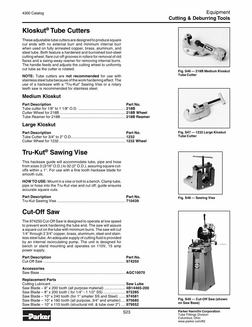
Fig. S46 — 218B Medium KloskutTube Cutter
Fig. S48 — Sawing Vise
Fig. S47 — 1232 Large KloskutTube Cutter
Fig. S49 — Cut-Off Saw (shownon Saw Base)
Kloskut® Tube CuttersThese adjustable tube cutters are designed to produce squarecut ends with no external burr and minimum internal burrwhen used on fully annealed copper, brass, aluminum, andsteel tube. Both feature a hardened and burnished tool-steelcutting wheel, flare cut-off grooves in rollers for removal of oldflares and a swing-away reamer for removing internal burrs.The handle feeds and adjusts the cutting wheel to uniformlycut tube as the cutter is rotated.
NOTE: Tube cutters are not recommended for use withstainless steel tube because of the work hardening effect. Theuse of a hacksaw with a “Tru-Kut” Sawing Vise or a rotaryteeth saw is recommended for stainless steel.
Medium Kloskut
Part Description Part No.Tube cutter for 1/8" to 1 1/8" O.D. ............................................. 218BCutter Wheel for 218B ............................................................... 218B WheelTube Reamer for 218B .............................................................. 218B Reamer
Large Kloskut
Part Description Part No.Tube Cutter for 3/4" to 2" O.D. ................................................... 1232Cutter Wheel for 1232................................................................ 1232 Wheel
Tru-Kut® Sawing ViseThis hacksaw guide will accommodate tube, pipe and hosefrom sizes 3 (3/16" O.D.) to 32 (2" O.D.), assuring square cut-offs within ± 1°. For use with a fine tooth hacksaw blade forsmooth cuts.
HOW TO USE: Mount in a vise or bolt to a bench. Clamp tube,pipe or hose into the Tru-Kut vise and cut off; guide ensuresaccurate square cuts.
Part Description Part No.Tru-Kut Sawing Vise .................................................................. 710439
Cut-Off SawThe 974250 Cut-Off Saw is designed to operate at low speedto prevent work hardening the tube end. The saw will assurea square cut on the tube with minimum burrs. The saw will cut1/4" through 2 3/4" copper, brass, aluminum, steel and stain-less steel tube. An adequate supply of cutting fluid is providedby an internal recirculating pump. The unit is designed forbench or stand mounting and operates on 110V, 15 amppower supply.
Part Description Part No.Cut-Off Saw ............................................................................... 974250
AccessoriesSaw Base ................................................................................... AGC10070
Replacement PartsCutting Lubricant ........................................................................ Saw LubeSaw Blade – 8" x 200 tooth (all purpose material) .................... 4B14465-200Saw Blade – 8" x 200 tooth ( for 1/4" - 1 1/2" SS) ..................... 972285Saw Blade – 10" x 240 tooth (for 1" smaller SS and Steel) ...... 974581Saw Blade – 10" x 180 tooth (all purpose, 3/4" and smaller) .... 975685Saw Blade – 10" x 110 tooth (structural mtl. & tube over 2") .... 979552
Cutting & Deburring Tools

Parker Hannifin CorporationTube Fittings DivisionColumbus, Ohiowww.parker.com/tfd
S24
4300 Catalog Equipment
Fig. S50 — 226A In-ExDeburr Tool
Fig. S51 — Power Deburr Tool
In-Ex® Tube Deburring Tool 226AA quick twist of the wrist will deburr either the O.D. or the I.D.of the tube end. Parker’s In-Ex deburrer can be used onannealed steel, stainless steel, copper and aluminum, fortube sizes 1/8" to 1 5/8" O.D.
Part Description Part No.In-Ex Deburring Tool ................................................................. 226ABlades for 226A Tube Deburr Tool ............................................ 226A Blades
Power Deburr ToolThe Parker Power Deburr Tool is designed for deburring theI.D. and O.D. of 1/4" through 2" steel, stainless steel, copperand aluminum tube. The lightweight unit incorporates a modulardesign which allows Parker’s Cut-Off Saw, part number974250, to be easily mounted on the top. The Power DeburrTool requires 110V/10A power supply.
Dimensions: L – 20", W – 18", H – 9".
Part Description Part No.Power Deburr Tool ..................................................................... 974250
Replacement PartsI.D. Deburr Cone ........................................................................ 971816O.D. Deburr Blades (six blade set) ............................................ 910485
Cutting & Deburring Tools

Parker Hannifin CorporationTube Fittings DivisionColumbus, Ohiowww.parker.com/tfd
S25
4300 Catalog Equipment
Fig. S52 — SAE Flange & Seal
Fig. S53 — 1090 Machine
Parflange® 1090SAE Flanging System
Part No.1090/440
The Parflange System, developed by Parker, is an originalconnection system for tubes up to 80mm O.D. In a few stepsthe Parflange System gives a reliable and leak free connec-tion. In one quick opertion the tube is flanged 90° with theParflange machine to create a flat face. Next, using thespecially designed Parflange Seal the sealing process isaccomplished. Completing the operation is the connectionwhich is secured by the use of standard code 61 and 62 (3000and 6000 psi) SAE flanges. The Parker Parflange System, asimple safe and dependable operation for connection of highpressure tubes without welding. Contact TFD for details.
A VHS video is included with each unit to provide instructionsfor proper use.
1090 Benefits
• Minimal set-up required• No special operator skills needed• Flange operation completed in less than one minute
• Limited maintenance required• Faster than welding• No post-cleaning required
• No unnecessary inspection required
Technical Characteristics
• Tube sizes 16mm to 80mm O.D.• Self opening and closing of the dies• 20 second cycle time
• Two die closing buttons for safety• Foot pedal control for cycle start• Integrated lubrication for flanging pin
• 440V 3 phase• H – 52", W – 30", L – 63"
See Section M for flange, seal and technical information.
Tooling available upon request.
Flanging Tools
Parker Hannifin CorporationTube Fittings DivisionColumbus, Ohiowww.parker.com/tfd
S26
4300 Catalog Equipment
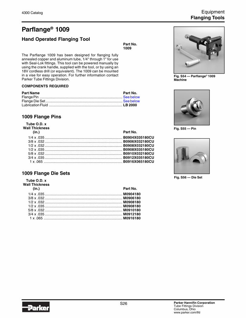
Fig. S54 — Parflange® 1009Machine
Fig. S55 — Pin
Fig. S56 — Die Set
Parflange® 1009Hand Operated Flanging Tool
Part No.1009
The Parflange 1009 has been designed for flanging fullyannealed copper and aluminum tube, 1/4" through 1" for usewith Seal-Lok fittings. This tool can be powered manually byusing the crank handle, supplied with the tool, or by using an18V cordless drill (or equivalent). The 1009 can be mountedin a vise for easy operation. For further information contactParker Tube Fittings Division.
COMPONENTS REQUIRED
Part Name Part No.Flange Pin .................................................................................. See belowFlange Die Set ............................................................................ See belowLubrication Fluid ......................................................................... LB 2000
1009 Flange PinsTube O.D. x
Wall Thickness(in.) Part No.
1/4 x .035 ............................................................................. B0904X035180CU3/8 x .032 ............................................................................. B0906X032180CU1/2 x .032 ............................................................................. B0908X032180CU1/2 x .035 ............................................................................. B0908X035180CU5/8 x .032 ............................................................................. B0910X032180CU3/4 x .035 ............................................................................. B0912X035180CU1 x .065 .............................................................................. B0916X065180CU
1009 Flange Die SetsTube O.D. x
Wall Thickness(in.) Part No.
1/4 x .035 ............................................................................. M09041803/8 x .032 ............................................................................. M09061801/2 x .032 ............................................................................. M09081801/2 x .035 ............................................................................. M09081805/8 x .032 ............................................................................. M09101803/4 x .035 ............................................................................. M09121801 x .065 .............................................................................. M0916180
Flanging Tools

Parker Hannifin CorporationTube Fittings DivisionColumbus, Ohiowww.parker.com/tfd
S27
4300 Catalog Equipment
Fig. S57 — Parflange® 1040Machine
Fig. S58 — Die
Fig. S59 — Pin
Parflange® 1040High-Speed Seal-Lok Flanging and 37° Flaring System• Eliminates braze joint• Minimum cleaning prior to and after flanging• Flanges in only 20% of brazing time
• Meets SAE J1453 performance requirementsElectrical Power: 220/440 volts**, 60 Hz, 16/10 amps
** Machine is equipped with 220/440 volt selector switch
Air Supply: 80 to 120 psi shop airDimensions: Height: 41 inches (1020mm)
Width: 28 inches (705mm)Depth: 32 inches (805mm)
Weight: Basic 1040 Unit: 675 lbs. (306 kg.)Automatic Sleeve Loader: 40 lbs. (18.1 kg.)Each Die (typical): 4 lbs. (1.8 kg.)
See Bulletin 4390-1040A for more details.
A VHS video is included to provide instructions for proper use.
COMPONENTS REQUIRED
Part Name Part No.Parflange 1040 .......................................................................... 1040Flanging Pin ................................................................................ See page S29Flanging Die Set ......................................................................... See page S29Flaring Pin .................................................................................. See page S37Flaring Die Set ............................................................................ See page S37Lubrication Fluid ........................................................................ LB 2000Die Adjustment Shims ............................................................... Shim Kit
OPTIONAL ACCESSORIESOperation Video ......................................................................... 4390-TFVAutomatic Sleeve Loader .......................................................... 1040 Loader
Flanging Tools

Parker Hannifin CorporationTube Fittings DivisionColumbus, Ohiowww.parker.com/tfd
S28
4300 Catalog Equipment
Fig. S60 — Parflange® 1025Machine
Fig. S61 — Flanging Pin
Fig. S63 — Flanging DieSet
CAUTION: Extension cordsare not recommended andcould cause damage to themachine due to a lack ofpower supply.
Fig. S62 — LB 2000
Parflange® 1025Bench-Top Flanging and 37° Flaring SystemTooling must be ordered separately
• Eliminates braze joint• Compact, lightweight design• Bench mountable• Easy to operate• Uses same tooling as Parflange 1040• Available in 110-volt single-phase or 440-volt 3-phase
(please specify by ordering 1025/110 or 1025/440)• Flanges or flares tube in less than 20 seconds• For tube sizes 1/4" O.D. thru 1 1/2" O.D. (steel); and
1/4" O.D. thru 1" O.D. (stainless steel).Tooling is also available for comparable metric tube sizes.
Electrical Power: 110V/20A single-phase, or 440V/3-phase/2.1APower Cable Length: 8 feet long (2.5 meters)
Dimensions: Height: 18 1/8 inches (460mm)Width: 15 3/8 inches (390mm)Depth: 26 3/8 inches (670mm)
Weight: Basic Unit: 175 lbs. (80 kg.)Each Die (typical): 4 lbs. (1.8 kg.)
Flanging Pin Lubrication Fluid: LB2000
See Bulletin 4390-1025A, 4390-1025 or 4390-B5-USA formore details.
A VHS video is included to provide instructions for proper use.
COMPONENTS REQUIRED
Part Name Part No.Parflange 1025 .......................................................................... 1025/110Parflange 1025 ........................................................................... 1025/440Flanging Pin ................................................................................ See page S29Flanging Die Set ......................................................................... See page S29Flaring Pin .................................................................................. See page S37Flaring Die Set ............................................................................ See page S37Lubrication Fluid ........................................................................ LB 2000Die Adjustment Shims ............................................................... Shim Kit
REPLACEMENT PART
Part Name Part No.Tube Stop .................................................................................. 1025/0281014
OPTIONAL ACCESSORIESOperation Video ......................................................................... 4390-TFV
Flanging Tools

Parker Hannifin CorporationTube Fittings DivisionColumbus, Ohiowww.parker.com/tfd
S29
4300 Catalog Equipment
Table S5 — Pin & Die Part Numbers for Inch Sizes
Note: Use "-SS" suffix after part number for flanging tools for stainless steel tube.Contact the Tube Fittings Division for sizes and/or materials not listed, or foradditional SS sizes released for limited use.
Table S6 — Pin & Die Part Numbers for Metric Sizes
1) Flanging tools (90°/180°) listed are for carbon steel tube.Contact the Tube Fittings Division for metric flanging toolsfor tube materials other than corbon steel or for sizes notlisted.
Inch and Metric Flanging Tooling for1025 and 1040 Parflange Machines
Flanging Tools
Tube SizeO.D. x Tooling for 90°/180° Tube Flanging
AvailableFlangingTooling
Tube SizeO.D. x
Tooling for 90°/180° Tube Flanging
AvailableFlangingTooling
WallThickness
Flange Pin and Die Set Pin Die
1040 1025Wall
Thickness Pin Die1040 1025
(in.) Part Number Part Number Part Number S SS S SS (mm) Part Number Part Number S SS S SS1/4 x .028 4004X028180 B4004X028180 M4004X028180 • • 6 x 1 B4018006X1M M4018006X1M • •1/4 x .035 4004X035180 B4004X035180 M4004X035180 • • • • 6 x 1.5 B4018006X1.5M M4018006X1.5M • •1/4 x .049 4004X049180 B4004X049180 M4004X049180 • • 8 x 1 B4018008X1M M4018008X1M • •3/8 x .035 4006X035180 B4006X035180 M4006X035180 • • • • 8 x 1.5 B4018008X1.5M M4018008X1.5M • •3/8 x .049 4006X049180 B4006X049180 M4006X049180 • • • • 10 x 1 B4018010X1M M4018010X1M • •3/8 x .065 4006X065180 B4006X065180 M4006X065180 • • • • 10 x 1.5 B4018010X1.5M M4018010X1.5M • •1/2 x .035 4008X035180 B4008X035180 M4008X035180 • • • • 10 x 2 B4018010X2M M4018010X2M • •1/2 x .049 4008X049180 B4008X049180 M4008X049180 • • • • 12 x 1 B4018012X1M M4018012X1M • •1/2 x .065 4008X065180 B4008X065180 M4008X065180 • • • • 12 x 1.5 B4018012X1.5M M4018012X1.5M • • • •1/2 x .083 4008X083180 B4008X083180 M4008X083180 • • • • 12 x 2 B4018012X2M M4018012X2M • •5/8 x .049 4010X049180 B4010X049180 M4010X049180 • • • • 15 x 1.5 B4018015X1.5M M4018015X1.5M • •5/8 x .065 4010X065180 B4010X065180 M4010X065180 • • • • 15 x 2 B4018015X2M M4018015X2M • •5/8 x .083 4010X083180 B4010X083180 M4010X083180 • • • • 16 x 1 B4018016X1M M4018016X1M • •5/8 x .095 4010X095180 B4010X095180 M4010X095180 • • • • 16 x 1.5 B4018016X1.5M M4018016X1.5M • •5/8 x .109 4010X109180 B4010X109180 M4010X109180 • • 16 x 2 B4018016X2M M4018016X2M • • • •5/8 x .120 4010X120180 B4010X120180 M4010X120180 • • 16 x 2.5 B4018016X2.5M M4018016X2.5M • •3/4 x .049 4012X049180 B4012X049180 M4012X049180 • • • • 18 x 1 B4018018X1M M4018018X1M • •3/4 x .065 4012X065180 B4012X065180 M4012X065180 • • • • 18 x 1.5 B4018018X1.5M M4018018X1.5M • •3/4 x .083 4012X083180 B4012X083180 M4012X083180 • • • • 18 x 2 B4018018X2M M4018018X2M • •3/4 x .095 4012X095180 B4012X095180 M4012X095180 • • • • 20 x 2 B4018020X2M M4018020X2M • • • •3/4 x .109 4012X109180 B4012X109180 M4012X109180 • • • • 20 x 2.5 B4018020X2.5M M4018020X2.5M • •3/4 x .120 4012X120180 B4012X120180 M4012X120180 • • • • 20 x 3 B4018020X3M M4018020X3M • •1 x .065 4016X065180 B4016X065180 M4016X065180 • • • • 22 x 1.5 B4018022X1.5M M4018022X1.5M • •1 x .083 4016X083180 B4016X083180 M4016X083180 • • • • 22 x 2 B4018022X2M M4018022X2M • •1 x .095 4016X095180 B4016X095180 M4016X095180 • • • • 22 x 2.5 B4018022X2.5M M4018022X2.5M • •1 x .109 4016X109180 B4016X109180 M4016X109180 • • • 22 x 3 B4018022X3M M4018022X3M • •1 x .120 4016X120180 B4016X120180 M4016X120180 • • • 25 x 2 B4018025X2M M4018025X2M • •1 x .134 4016X134180 B4016X134180 M4016X134180 • • • 25 x 2.5 B4018025X2.5M M4018025X2.5M • •1 x .148 4016X148180 B4016X148180 M4016X148180 • 25 x 3 B4018025X3M M4018025X3M • •1 x .156 4016X156180 B4016X156180 M4016X156180 • 25 x 3.5 B4018025X3.5M M4018025X3.5M • •1 x .188 4016X188180 B4016X188180 M4016X188180 • 25 x 4 B4018025X4M M4018025X4M •1 1/4 x .083 4020X083180 B4020X083180 M4020X083180 • • • 28 x 2 B4018028X2M M4018028X2M • •1 1/4 x .095 4020X095180 B4020X095180 M4020X095180 • • • 28 x 2.5 B4018028X2.5M M4018028X2.5M • •1 1/4 x .109 4020X109180 B4020X109180 M4020X109180 • • • 30 x 2 B4018030X2M M4018030X2M • •1 1/4 x .120 4020X120180 B4020X120180 M4020X120180 • • • 30 x 3 B4018030X3M M4018030X3M • •1 1/4 x .134 4020X134180 B4020X134180 M4020X134180 • 30 x 3.5 B4018030X3.5M M4018030X3.5M •1 1/4 x .148 4020X148180 B4020X148180 M4020X148180 • 30 x 4 B4018030X4M M4018030X4M •1 1/4 x .156 4020X156180 B4020X156180 M4020X156180 • 32 x 3 B4018032X3M M4018032X3M • •1 1/4 x .188 4020X188180 B4020X188180 M4020X188180 • 32 x 4 B4018032X4M M4018032X4M •1 1/2 x .065 4024X065180 B4024X065180 M4024X065180 • • 35 x 3 B4018035X3M M4018035X3M • •1 1/2 x .083 4024X083180 B4024X083180 M4024X083180 • • 38 x 3 B4018038X3M M4018038X3M •1 1/2 x .095 4024X095180 B4024X095180 M4024X095180 • • 38 x 4 B4018038X4M M4018038X4M •1 1/2 x .109 4024X109180 B4024X109180 M4024X109180 • 38 x 5 B4018038X5M M4018038X5M •1 1/2 x .120 4024X120180 B4024X120180 M4024X120180 • •1 1/2 x .134 4024X134180 B4024X134180 M4024X134180 •1 1/2 x .156 4024X156180 B4024X156180 M4024X156180 •1 1/2 x .188 4024X188180 B4024X188180 M4024X188180 •2 x .083 4032X083180 B4032X083180 M4032X083180 •2 x .095 4032X095180 B4032X095180 M4032X095180 •2 x .120 4032X120180 B4032X120180 M4032X120180 •

Parker Hannifin CorporationTube Fittings DivisionColumbus, Ohiowww.parker.com/tfd
S30
4300 Catalog Equipment
Fig. S64 — 210A CombinationFlarer
Fig. S65 — Vise Block withFlaring Pin
Combination FlarerPart No.210A
For 1/8", 3/16", 1/4", 5/16", 3/8", 1/2", 5/8", O.D. tube.
The combination flarer is a 7-in-1 impact tool for flaring (37°)soft copper, aluminum and fully annealed steel tube, sizes 2(1/8" O.D.) through 10 (5/8" O.D.). Maximum wall thickness:1/8" to 3/8" is 15% of tube O.D., 1/2" and larger is 10% of tubeO.D.
HOW TO USE: Insert tube into proper flare hole and fastenwith clamping screw. Set hardened-steel flaring punch in tubeand form flare with a few sharp hammer blows. (Tube shouldnot project more than 1/16" above top of block.)
Vise Block with Flaring PinThese impact 37° flaring tools are for use with copper, alum-inum alloy, and thin wall steel or stainless steel. Separate tool-ing set for each tube size 4 (1/4" O.D.) through 24 (1 1/2"O.D.). Maximum wall thickness: 1/8" to 3/8" is 15% of tubeO.D., 1/2" and larger is 10% of tube O.D.
HOW TO USE: Clamp tube flush in matching halves of blockin a bench vise. Give hardened steel flaring pin a few sharpblows with a hammer to form the flare.
Tube O.D.Size (in.) Part No.
4 1/4 ........................................................................... 4-28665 5/16 .......................................................................... 5-28666 3/8 ........................................................................... 6-28668 1/2 ........................................................................... 8-2866
10 5/8 ........................................................................... 10-286612 3/4 ........................................................................... 12-286614 7/8 ........................................................................... 14-286616 1 ............................................................................ 16-286620 1 1/4 ......................................................................... 20-286624 1 1/2 ......................................................................... 24-2866
Order vise block with flaring pin using part numbers above.The block and pin may be ordered separately by suffixing thepart number with either Pin or Block.
4-2866 BlockPart Number Example:
Flaring Tools

Parker Hannifin CorporationTube Fittings DivisionColumbus, Ohiowww.parker.com/tfd
S31
4300 Catalog Equipment
Fig. S68 — Flaring Pin
Fig. S67 — PIE
Fig. S66 — Flaring Die Set
Manual Flaring Tool Vise Blockand Flaring Pin — Metric TubeThese 37° flaring tools are designed for use in a vise whenflaring metric tube from 6mm O.D. to 38mm O.D.
From 20mm size tube and upward it is necessary to use a pre-flaring pin to start the flare.
• Clamp tube flush in black halves• Flare tube by hammering the flaring pin.
A separate block and pin set is used for each tube size.
Pre-Flaring PinsTube O.D.
(mm) Part No.
20 ......................................................................................... PIE25 ......................................................................................... PIE30 ......................................................................................... PIE32 ......................................................................................... PIE38 ......................................................................................... PIE
Flaring PinsTube O.D.
(mm) Part No.
6 .......................................................................................... P174088 .......................................................................................... P17408
10 ......................................................................................... P1740812 ......................................................................................... P1741414 ......................................................................................... P1741415 ......................................................................................... P1741416 ......................................................................................... P1741418 ......................................................................................... P1741820 ......................................................................................... P1741825 ......................................................................................... P1742230 ......................................................................................... P1743232 ......................................................................................... P1743238 ......................................................................................... P17438
Vise BlocksTube O.D.
(mm) Part No.
6 .......................................................................................... M274068 .......................................................................................... M27408
10 ......................................................................................... M2741012 ......................................................................................... M2741214 ......................................................................................... M2741415 ......................................................................................... M2741516 ......................................................................................... M2741618 ......................................................................................... M2741820 ......................................................................................... M2742025 ......................................................................................... M2742530 ......................................................................................... M2743032 ......................................................................................... M2743238 ......................................................................................... M27438
Flaring Tools
Parker Hannifin CorporationTube Fittings DivisionColumbus, Ohiowww.parker.com/tfd
S32
4300 Catalog Equipment
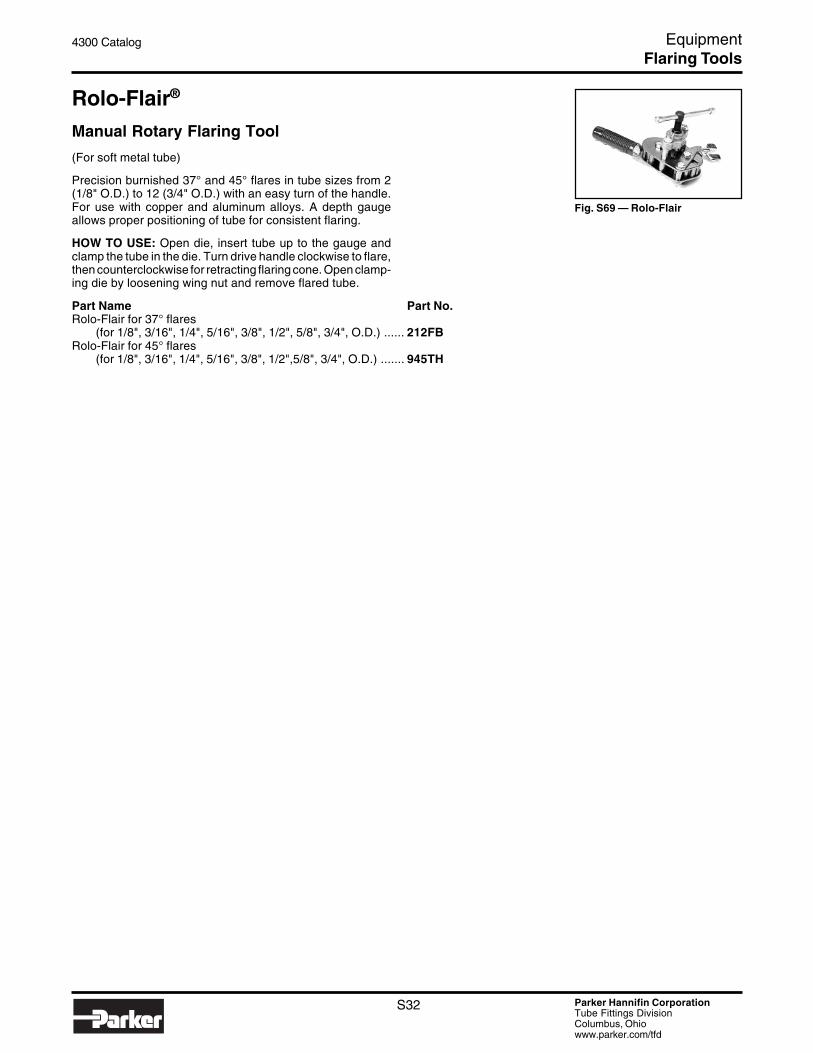
Rolo-Flair®
Manual Rotary Flaring Tool
(For soft metal tube)
Precision burnished 37° and 45° flares in tube sizes from 2(1/8" O.D.) to 12 (3/4" O.D.) with an easy turn of the handle.For use with copper and aluminum alloys. A depth gaugeallows proper positioning of tube for consistent flaring.
HOW TO USE: Open die, insert tube up to the gauge andclamp the tube in the die. Turn drive handle clockwise to flare,then counterclockwise for retracting flaring cone. Open clamp-ing die by loosening wing nut and remove flared tube.
Part Name Part No.Rolo-Flair for 37° flares
(for 1/8", 3/16", 1/4", 5/16", 3/8", 1/2", 5/8", 3/4", O.D.) ...... 212FBRolo-Flair for 45° flares
(for 1/8", 3/16", 1/4", 5/16", 3/8", 1/2",5/8", 3/4", O.D.) ....... 945TH
Fig. S69 — Rolo-Flair
Flaring Tools

Parker Hannifin CorporationTube Fittings DivisionColumbus, Ohiowww.parker.com/tfd
S33
4300 Catalog Equipment
Fig. S76 — Carrying Case
Fig. S70 — Hydra-Tool
Fig. S71 — Electric Pump
Fig. S72 — Hand Pump
Fig. S73 — Flaring Cone
Fig. S74 — Die Ring
Hydra-ToolHydraulic Flaring And Pre-Setting Tool
Flaring
An efficient dependable device for 37° and 45° flaring of steel,stainless steel and copper tube. This task is made easythrough hydraulic power provided by a hand or electric pump.The equipment is portable and easy to use.
This tool accommodates dies for tubes ranging in inch sizesfrom 4 through 32 (1/4" through 2" outside diameters) with wallthicknesses as great as .134", and metric sizes from 6mmthrough 50mm. The hydraulic “push” of the Hydra-Tool flaresthe tube to a 37° flare angle. A gauge can be provided toenable the operator to determine the pressure required toadequately flare any given material and wall thickness of thetube. Complete instructions are included with the Hydra-Tool.See bulletin 4392-B10. See the following for Hydra-Tool basicunit or kit, and choice of power sources and necessarytooling.
NOTE: Flaring die sets and other tooling are available in non-standard sizes upon request from the factory.
See Appendix for flaring pressures.
A VHS video is included to provide instructions for proper use.
COMPONENTS REQUIRED
Part Name Part No.Hydra-Tool (basic unit) .............................................................. 710400BHydra-Tool Male Adapter ........................................................... 6-8 F50L0-S“T” Adapter for Gauge ................................................................ 6 R6LO-SHose Assembly (for hand or electric pumps) ............................ 910004Adapter for Gauge ..................................................................... 6 G6L-SPressure Gauge (0 - 10,000 psi) ............................................... 900044Electric Hydraulic Pump (10,000 psi; 1/2 hp; 40-125 volt) ........ 900085Hand Hydraulic Pump (10,000 psi; 2 speed) ............................ 900086Die Ring (1/4" - 1 1/4") (6mm - 32mm) ...................................... 710416ADie Ring (1 1/2" - 2") (35mm - 50mm) ....................................... 71041237° Flaring Cone (1/4" - 1 1/4") (6mm - 32mm) ......................... 71041937° Flaring Cone (1 1/2" - 2") (35mm - 50mm) .......................... 710411Die Retainer Assembly (1/4" - 1 1/4") (6mm - 32mm) ............... 710424-1Die Retainer Assembly (1 1/2" - 2") (35mm - 50mm) ................ 710424-2Flaring Die Sets .......................................................................... See pages S34 – S35Lubricant .................................................................................... STP45° Flaring Cone (1/4" - 1") ....................................................... 910312
REPLACEMENT PART
Part Name Part No.Tube Stop Assembly ................................................................. 710420B
OPTIONAL ACCESSORIES
Part Name Part No.Hydra-Tool Carrying Case ......................................................... 720377
Sturdy wood case for Hydra-Tool and tooling.(Hydra-Tool kit is shipped in this carrying case.)
Operation Video ......................................................................... 4390-TFV
Fig. S75 — Die Retainer
Flaring Tools
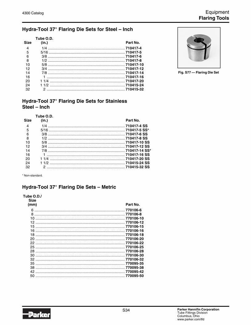
Parker Hannifin CorporationTube Fittings DivisionColumbus, Ohiowww.parker.com/tfd
S34
4300 Catalog Equipment
Fig. S77 — Flaring Die Set
Hydra-Tool 37° Flaring Die Sets for Steel – Inch
Tube O.D.Size (in.) Part No.
4 1/4 ........................................................................... 710417-45 5/16 .......................................................................... 710417-56 3/8 ........................................................................... 710417-68 1/2 ........................................................................... 710417-8
10 5/8 ........................................................................... 710417-1012 3/4 ........................................................................... 710417-1214 7/8 ........................................................................... 710417-1416 1 ............................................................................ 710417-1620 1 1/4 ......................................................................... 710417-2024 1 1/2 ......................................................................... 710415-2432 2 ............................................................................ 710415-32
Hydra-Tool 37° Flaring Die Sets for StainlessSteel – Inch
Tube O.D.Size (in.) Part No.
4 1/4 ........................................................................... 710417-4 SS5 5/16 .......................................................................... 710417-5 SS*6 3/8 ........................................................................... 710417-6 SS8 1/2 ........................................................................... 710417-8 SS
10 5/8 ........................................................................... 710417-10 SS12 3/4 ........................................................................... 710417-12 SS14 7/8 ........................................................................... 710417-14 SS*16 1 ............................................................................ 710417-16 SS20 1 1/4 ......................................................................... 710417-20 SS24 1 1/2 ......................................................................... 710415-24 SS32 2 ............................................................................ 710415-32 SS
* Non-standard.
Hydra-Tool 37° Flaring Die Sets – Metric
Tube O.D./Size(mm) Part No.
6 ........................................................................................ 770106-68 ........................................................................................ 770106-8
10 ....................................................................................... 770106-1012 ....................................................................................... 770106-1215 ....................................................................................... 770106-1516 ....................................................................................... 770106-1618 ....................................................................................... 770106-1820 ....................................................................................... 770106-2022 ....................................................................................... 770106-2225 ....................................................................................... 770106-2528 ....................................................................................... 770106-2830 ....................................................................................... 770106-3032 ....................................................................................... 770106-3235 ....................................................................................... 770095-3538 ....................................................................................... 770095-3842 ....................................................................................... 770095-4250 ....................................................................................... 770095-50
Flaring Tools

Parker Hannifin CorporationTube Fittings DivisionColumbus, Ohiowww.parker.com/tfd
S35
4300 Catalog Equipment
Fig. S78 — Hydra-Tool Kit
Hydra-Tool 45° Flaring Die Sets – Inch
Tube O.D.Size (in.) Part No.
4 1/4 ........................................................................... 977420-46 3/8 ........................................................................... 977420-68 1/2 ........................................................................... 977420-8
10 5/8 ........................................................................... 977420-1012 3/4 ........................................................................... 977420-1214 7/8 ........................................................................... 977420-1416 1 ............................................................................ 977420-16
Hydra-Tool Kit
Part Name Part No.Hydra-Tool Kit (for use with electric or hand pump) .................. 720370B-3
Includes basic unit, gauge, Hydra-Tool connector,lubricant, adapter, carrying case, hose assembly,operation manual and video.
Flaring Tools

Parker Hannifin CorporationTube Fittings DivisionColumbus, Ohiowww.parker.com/tfd
S36
4300 Catalog Equipment
Hydraulic 1015 Flaring MachineThe 1015 machine, has been specifically designed for flaringhydraulic tube to a 37° angle. This machine is very reliableand remarkable for its efficiency and simplicity of operation.
Part Name Part No.Hand Pump Model ..................................................................... 1015-1
Hydraulic power is generated by a hand operated pump. Apressure gauge is provided to enable the operator to quicklysee the required flaring pressure according to tube O.D. andwall thickness. The complete unit is mounted on a base plate,and includes 37° cone.
Dimensions: H – 24" W – 10" L – 24"
Application range
The 1015 machine is capable of flaring tube from 1/4" O.D. to1 1/2" O.D. or from 6mm O.D. to 42mm O.D.
FLARING COMPONENTS
Part Name Part No.Replacement 37° Flaring Cone ................................................. P7415-6/4237° Flaring Die Sets ................................................................... See below
Tube Die Sets – InchTube O.D.
(in.) Part No.
1/4 ....................................................................................... M 047415-15/16 ...................................................................................... M 157408-13/8 ....................................................................................... M 067415-11/2 ....................................................................................... M 0874155/8 ....................................................................................... M 1074153/4 ....................................................................................... M 1274151 ........................................................................................ M 167415
1 1/4 ..................................................................................... M 2074151 1/2 ..................................................................................... M 157438
Tube Die Sets – MetricTube O.D.
(mm) Part No.
6 ........................................................................................ M 157406-18 ........................................................................................ M 157408-1
10 ....................................................................................... M 157410-112 ....................................................................................... M 15741214 ....................................................................................... M 15741415 ....................................................................................... M 15741516 ....................................................................................... M 15741618 ....................................................................................... M 15741820 ....................................................................................... M 15742025 ....................................................................................... M 15742530 ....................................................................................... M 15743032 ....................................................................................... M 15743238 ....................................................................................... M 157438
Parflange® 1025 and Parflange® 104037° Flaring and Flanging SystemsParker’s Parflange 1025 and 1040 machines are designed tocreate 37° flared tube ends. For more detailed information,refer to pages S27 and S28. See page S37 for flaring tool partnumbers.
Fig. S81 — Parflange 1040
Fig. S82 — Parflange 1025
Fig. S80 — Flaring Die Set
Fig. S79 — 1015-1
Flaring Tools
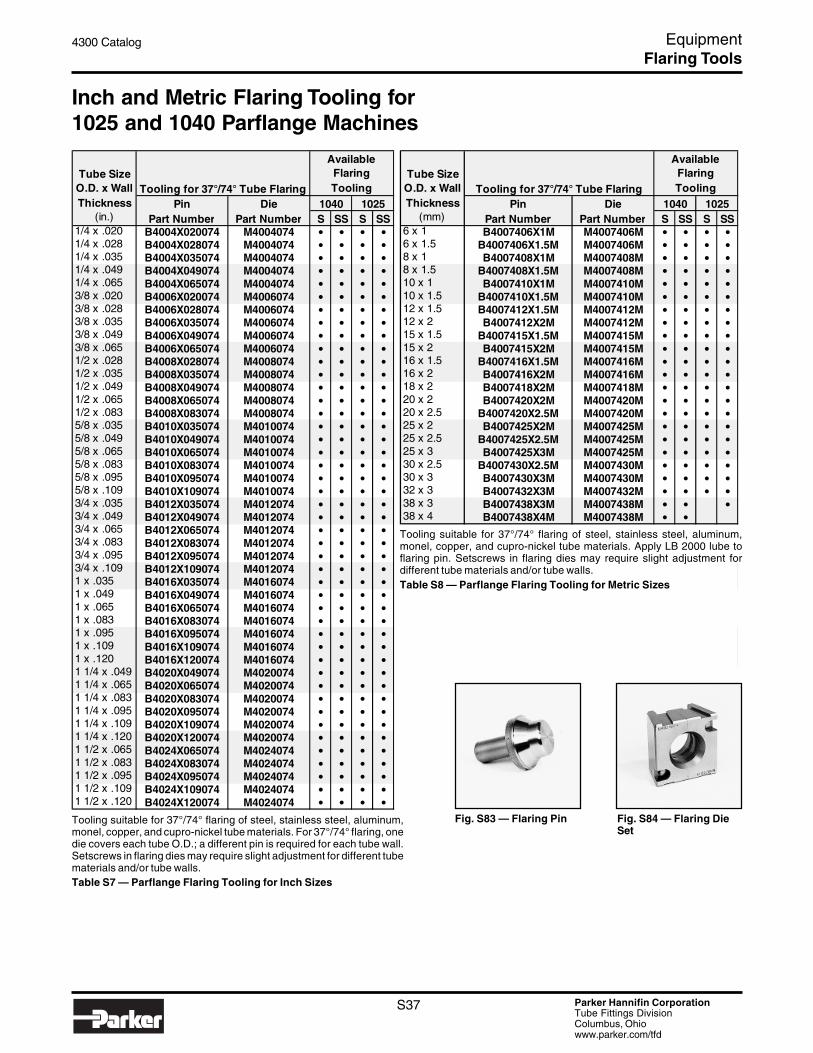
Parker Hannifin CorporationTube Fittings DivisionColumbus, Ohiowww.parker.com/tfd
S37
4300 Catalog Equipment
Tooling suitable for 37°/74° flaring of steel, stainless steel, aluminum,monel, copper, and cupro-nickel tube materials. For 37°/74° flaring, onedie covers each tube O.D.; a different pin is required for each tube wall.Setscrews in flaring dies may require slight adjustment for different tubematerials and/or tube walls.Table S7 — Parflange Flaring Tooling for Inch Sizes
Fig. S83 — Flaring Pin Fig. S84 — Flaring DieSet
Inch and Metric Flaring Tooling for1025 and 1040 Parflange Machines
Tooling for 37°/74° Tube Flaring
AvailableFlaringTooling Tooling for 37°/74° Tube Flaring
AvailableFlaringTooling
Pin Die 1040 1025 Pin Die 1040 1025(in.) Part Number Part Number S SS S SS (mm) Part Number Part Number S SS S SS
1/4 x .020 B4004X020074 M4004074 • • • • 6 x 1 B4007406X1M M4007406M • • • •1/4 x .028 B4004X028074 M4004074 • • • • 6 x 1.5 B4007406X1.5M M4007406M • • • •1/4 x .035 B4004X035074 M4004074 • • • • 8 x 1 B4007408X1M M4007408M • • • •1/4 x .049 B4004X049074 M4004074 • • • • 8 x 1.5 B4007408X1.5M M4007408M • • • •1/4 x .065 B4004X065074 M4004074 • • • • 10 x 1 B4007410X1M M4007410M • • • •3/8 x .020 B4006X020074 M4006074 • • • • 10 x 1.5 B4007410X1.5M M4007410M • • • •3/8 x .028 B4006X028074 M4006074 • • • • 12 x 1.5 B4007412X1.5M M4007412M • • • •3/8 x .035 B4006X035074 M4006074 • • • • 12 x 2 B4007412X2M M4007412M • • • •3/8 x .049 B4006X049074 M4006074 • • • • 15 x 1.5 B4007415X1.5M M4007415M • • • •3/8 x .065 B4006X065074 M4006074 • • • • 15 x 2 B4007415X2M M4007415M • • • •1/2 x .028 B4008X028074 M4008074 • • • • 16 x 1.5 B4007416X1.5M M4007416M • • • •1/2 x .035 B4008X035074 M4008074 • • • • 16 x 2 B4007416X2M M4007416M • • • •1/2 x .049 B4008X049074 M4008074 • • • • 18 x 2 B4007418X2M M4007418M • • • •1/2 x .065 B4008X065074 M4008074 • • • • 20 x 2 B4007420X2M M4007420M • • • •1/2 x .083 B4008X083074 M4008074 • • • • 20 x 2.5 B4007420X2.5M M4007420M • • • •5/8 x .035 B4010X035074 M4010074 • • • • 25 x 2 B4007425X2M M4007425M • • • •5/8 x .049 B4010X049074 M4010074 • • • • 25 x 2.5 B4007425X2.5M M4007425M • • • •5/8 x .065 B4010X065074 M4010074 • • • • 25 x 3 B4007425X3M M4007425M • • • •5/8 x .083 B4010X083074 M4010074 • • • • 30 x 2.5 B4007430X2.5M M4007430M • • • •5/8 x .095 B4010X095074 M4010074 • • • • 30 x 3 B4007430X3M M4007430M • • • •5/8 x .109 B4010X109074 M4010074 • • • • 32 x 3 B4007432X3M M4007432M • • • •3/4 x .035 B4012X035074 M4012074 • • • • 38 x 3 B4007438X3M M4007438M • • •3/4 x .049 B4012X049074 M4012074 • • • • 38 x 4 B4007438X4M M4007438M • •3/4 x .065 B4012X065074 M4012074 • • • •3/4 x .083 B4012X083074 M4012074 • • • •3/4 x .095 B4012X095074 M4012074 • • • •3/4 x .109 B4012X109074 M4012074 • • • •1 x .035 B4016X035074 M4016074 • • • •1 x .049 B4016X049074 M4016074 • • • •1 x .065 B4016X065074 M4016074 • • • •1 x .083 B4016X083074 M4016074 • • • •1 x .095 B4016X095074 M4016074 • • • •1 x .109 B4016X109074 M4016074 • • • •1 x .120 B4016X120074 M4016074 • • • •1 1/4 x .049 B4020X049074 M4020074 • • • •1 1/4 x .065 B4020X065074 M4020074 • • • •1 1/4 x .083 B4020X083074 M4020074 • • • •1 1/4 x .095 B4020X095074 M4020074 • • • •1 1/4 x .109 B4020X109074 M4020074 • • • •1 1/4 x .120 B4020X120074 M4020074 • • • •1 1/2 x .065 B4024X065074 M4024074 • • • •1 1/2 x .083 B4024X083074 M4024074 • • • •1 1/2 x .095 B4024X095074 M4024074 • • • •1 1/2 x .109 B4024X109074 M4024074 • • • •1 1/2 x .120 B4024X120074 M4024074 • • • •
Tube Size O.D. x Wall Thickness
Tube Size O.D. x Wall Thickness
Tooling suitable for 37°/74° flaring of steel, stainless steel, aluminum,monel, copper, and cupro-nickel tube materials. Apply LB 2000 lube toflaring pin. Setscrews in flaring dies may require slight adjustment fordifferent tube materials and/or tube walls.Table S8 — Parflange Flaring Tooling for Metric Sizes
Flaring Tools

Parker Hannifin CorporationTube Fittings DivisionColumbus, Ohiowww.parker.com/tfd
S38
4300 Catalog Equipment
SAE Straight Thread Port Tapping Tools
Taps are available for SAE J1926-1 female straight threadports in sizes 2 through 32. Taps are bottoming type andmade from high speed tool steel.
SAE Overall Shank WrenchDash Length Dia. Flat SizeSize (in.) (in.) (in.) Part No.
2 2 23/32 0.318 0.238 ................... 5/16X24 UNF-2B3 2 15/16 0.381 0.286 ................... 3/8X24 UNF-2B4 3 5/16 0.323 0.242 ................... 7/16X20 UNF-2B5 3 3/8 0.367 0.275 ................... 1/2X20 UNF-2B6 3 19/32 0.429 0.322 ................... 9/16X18 UNF-2B8 4 1/4 0.590 0.442 ................... 3/4X16 UNF-2B
10 4 11/16 0.697 0.523 ................... 7/8X14 UNF-2B12 5 1/8 0.896 0.672 ................... 1 1/16X12 UNF-2B14 5 7/16 1.021 0.766 ................... 1 3/16X12 UNF-2B16 5 3/4 1.108 0.831 ................... 1 5/16X12 UNF-2B20 6 11/16 1.305 0.979 ................... 1 5/8X12 UNF-2B24 7 5/16 1.519 1.139 ................... 1 7/8X12 UNF-2B32 8 3/4 2.100 1.575 ................... 2 1/2X12 UNF-2B
Fig. S85 — SAE Straight ThreadPort Tapping Tool
Fig. S86 — SAE Straight ThreadPort Counterboring Tool
SAE Straight Thread Port Counterboring Tools
Parker offers counterboring tools for SAE J1926-1 femalestraight thread ports in sizes 2 through 32. Counterbores are4-fluted high speed tool steel.
RecommendedSAE Shank Shank Overall Pilot DrillDash Dia. Length Length or Bore SizeSize (in.) (in.) (in.) (in.) Part No.
2 1/2 1 1/2 2 1/2 0.266 ............ Y-347303 1/2 1 1/2 2 1/2 0.328 ............ Y-347314 1/2 1 1/2 2 41/64 0.377 ............ Y-347325 1/2 1 1/2 2 41/64 0.438 ............ Y-347336 3/4 1 1/2 2 47/64 0.500 ............ Y-347348 3/4 1 1/2 2 53/64 0.672 ............ Y-34735
10 1 2 3 29/64 0.797 ............ Y-3473612 1 2 3 19/32 0.969 ............ Y-3473714 1 2 3 41/64 1.095 ............ Y-3473816 1 2 3 41/64 1.220 ............ Y-3473920 1 1/2 2 3 37/64 1.530 ............ Y-3474024 1 1/2 2 3 37/64 1.780 ............ Y-3474132 1 1/2 2 3 49/64 2.405 ............ Y-34743
* See Appendix for recommended use of port tools.
Porting Tools
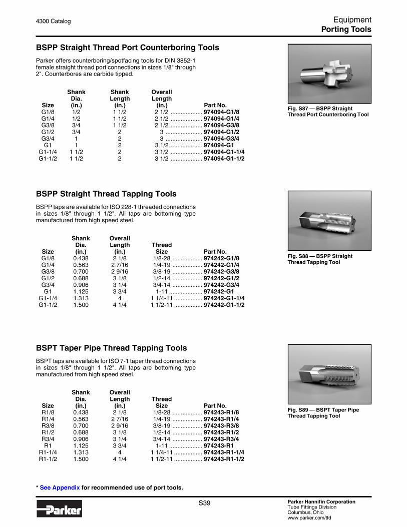
Parker Hannifin CorporationTube Fittings DivisionColumbus, Ohiowww.parker.com/tfd
S39
4300 Catalog Equipment
BSPP Straight Thread Port Counterboring Tools
Parker offers counterboring/spotfacing tools for DIN 3852-1female straight thread port connections in sizes 1/8" through2". Counterbores are carbide tipped.
Shank Shank OverallDia. Length Length
Size (in.) (in.) (in.) Part No.G1/8 1/2 1 1/2 2 1/2 ................... 974094-G1/8G1/4 1/2 1 1/2 2 1/2 ................... 974094-G1/4G3/8 3/4 1 1/2 2 1/2 ................... 974094-G3/8G1/2 3/4 2 3 ...................... 974094-G1/2G3/4 1 2 3 ...................... 974094-G3/4G1 1 2 3 1/2 ................... 974094-G1
G1-1/4 1 1/2 2 3 1/2 ................... 974094-G1-1/4G1-1/2 1 1/2 2 3 1/2 ................... 974094-G1-1/2
Fig. S87 — BSPP StraightThread Port Counterboring Tool
Fig. S88 — BSPP StraightThread Tapping Tool
BSPP Straight Thread Tapping Tools
BSPP taps are available for ISO 228-1 threaded connectionsin sizes 1/8" through 1 1/2". All taps are bottoming typemanufactured from high speed steel.
Shank OverallDia. Length Thread
Size (in.) (in.) Size Part No.G1/8 0.438 2 1/8 1/8-28 .................. 974242-G1/8G1/4 0.563 2 7/16 1/4-19 .................. 974242-G1/4G3/8 0.700 2 9/16 3/8-19 .................. 974242-G3/8G1/2 0.688 3 1/8 1/2-14 .................. 974242-G1/2G3/4 0.906 3 1/4 3/4-14 .................. 974242-G3/4G1 1.125 3 3/4 1-11 .................... 974242-G1
G1-1/4 1.313 4 1 1/4-11 ................. 974242-G1-1/4G1-1/2 1.500 4 1/4 1 1/2-11 ................. 974242-G1-1/2
BSPT Taper Pipe Thread Tapping Tools
BSPT taps are available for ISO 7-1 taper thread connectionsin sizes 1/8" through 1 1/2". All taps are bottoming typemanufactured from high speed steel.
Shank OverallDia. Length Thread
Size (in.) (in.) Size Part No.R1/8 0.438 2 1/8 1/8-28 .................. 974243-R1/8R1/4 0.563 2 7/16 1/4-19 .................. 974243-R1/4R3/8 0.700 2 9/16 3/8-19 .................. 974243-R3/8R1/2 0.688 3 1/8 1/2-14 .................. 974243-R1/2R3/4 0.906 3 1/4 3/4-14 .................. 974243-R3/4R1 1.125 3 3/4 1-11 .................... 974243-R1
R1-1/4 1.313 4 1 1/4-11 ................. 974243-R1-1/4R1-1/2 1.500 4 1/4 1 1/2-11 ................. 974243-R1-1/2
Fig. S89 — BSPT Taper PipeThread Tapping Tool
* See Appendix for recommended use of port tools.
Porting Tools

Parker Hannifin CorporationTube Fittings DivisionColumbus, Ohiowww.parker.com/tfd
S40
4300 Catalog Equipment
Fig. S91 — ISO 6149-1 StraightThread Port Tap
ISO 6149-1 Straight Thread Port Tapping Tools
ISO 6149-1 female straight thread port taps are available forM8 to M48 port sizes. Taps are bottoming type and made fromhigh speed steel.
Overall Shank WrenchLength Dia. Flat Size Thread
(in.) (in.) (in.) Size Part No.2 23/32 0.318 0.238 M8x1 ................... M8X12 15/16 0.381 0.286 M10x1 .................. M10X1-6H
3 3/8 0.367 0.275 M12x1.5 ................ M12X1.5-6H TAP3 19/32 0.429 0.322 M14x1.5 ................ M14X1.5-6H-TAP3 13/16 0.400 0.360 M16x1.5 ................ M16X1.5-6H-TAP4 1/32 0.542 0.406 M18x1.5 ................ M18X1.5-6H-TAP
4 11/16 0.697 0.523 M22x1.5 ................ M22X1.5-6H-TAP5 1/8 0.896 0.672 M27x2 .................. M27X2-6H-TAP5 3/4 1.108 0.831 M33x2 .................. M33X2-6H-TAP
7 1.430 1.072 M42x2 .................. M42X2-6H-TAP7 5/8 1.644 1.233 M48x2 .................. M48X2-6H
Fig. S90 — SAE Straight ThreadPort Counterboring Tool
NPTF Straight Thread Tapping Tools
NPTF taps are available for taper pipe thread connections insizes 1/8" through 1 1/2". All taps are bottoming type manu-factured from high speed steel.
Shank OverallDia. Length Thread(in.) (in.) Size Part No.
0.438 2 1/8 1/8-27 ............................................ 974244-1/80.563 2 7/16 1/4-18 ............................................ 974244-1/40.700 2 9/16 3/8-18 ............................................ 974244-3/80.688 3 1/8 1/2-14 ............................................ 974244-1/20.906 3 1/4 3/4-14 ............................................ 974244-3/41.125 3 3/4 1-11 1/2 .......................................... 974244-11.313 4 1 1/4-11 1/2 ....................................... 974244-1-1/41.500 4 1/4 1 1/2-11 1/2 ....................................... 974244-1-1/2
* See Appendix for recommended use of port tools.
Porting Tools

Parker Hannifin CorporationTube Fittings DivisionColumbus, Ohiowww.parker.com/tfd
S41
4300 Catalog Equipment
Fig. S92 — ISO 6149-1 StraightThread Port Counterboring Tool— Small Spotface
Fig. S93 — ISO 6149-1 StraightThread Port Counterboring Toolwith ID Groove
ISO 6149-1 Straight Thread PortCounterboring Tools — Small Spotface
ISO 6149-1 female straight thread port counterboring toolsare available with small spotface for M8 to M48 port sizes.Counterbores are 4-fluted*, carbide-tipped.
RecommendedShank Shank Overall Pilot Drill Use with
Dia. Length Length or Bore Size Thread(in.) (in.) (in.) (in.) Size Part No.
1/2 2 4 1/8 0.272 M8x1* ......... R1449B 1/2 2 4 1/8 0.348 M10x1* ........ R1450B 1/2 2 4 1/8 0.406 M12x1.5 ....... R1451B-S 1/2 2 4 1/8 0.484 M14x1.5 ....... R1452B-S 1/2 2 4 1/8 0.563 M16x1.5 ....... R1453B-S 1/2 2 4 1/8 0.641 M18x1.5 ....... R1454B-S 1/2 2 4 1/8 0.797 M22x1.5 ....... R1455B-S 3/4 2 1/2 5 0.969 M27x2 ......... R1456B-S 3/4 2 1/2 5 1.210 M33x2 ......... R1457B-S 3/4 2 1/2 5 1.565 M42x2 ......... R1458B-S 3/4 2 1/2 5 1.801 M48x2 ......... R1459B* M8 and M10 are 3-fluted
ISO 6149-1 Straight Thread PortCounterboring Tools with ID Groove
ISO 6149-1 female straight thread port counterboring toolsare available with identification groove for M8 to M48 portsizes. Counterbores are 4-fluted*, carbide-tipped.
RecommendedShank Shank Overall Pilot Drill Use with
Dia. Length Length or Bore Size Thread(in.) (in.) (in.) (in.) Size Part No.
1/2 2 4 1/8 0.272 M8x1* ......... R1449A1/2 2 4 1/8 0.348 M10x1* ........ R1450A1/2 2 4 1/8 0.406 M12x1.5 ....... R1451A1/2 2 4 1/8 0.484 M14x1.5 ....... R1452A1/2 2 4 1/8 0.563 M16x1.5 ....... R1453A1/2 2 4 1/8 0.641 M18x1.5 ....... R1454A1/2 2 4 1/8 0.797 M22x1.5 ....... R1455A3/4 2 1/2 5 0.969 M27x2 ......... R1456A3/4 2 1/2 5 1.210 M33x2 ......... R1457A3/4 2 1/2 5 1.565 M42x2 ......... R1458A3/4 2 1/2 5 1.801 M48x2 ......... R1459A
* M8 and M10 are 3-fluted
* See Appendix for recommended use of port tools.
Porting Tools

Parker Hannifin CorporationTube Fittings DivisionColumbus, Ohiowww.parker.com/tfd
S42
4300 Catalog Equipment
Fig. S94 — Ferulset®
Ferulset® Pre-Setting ToolFor Ferulok® flareless tube fittings.
Ferulset provides a fast and easy way to manually pre-set theferrule onto the tube with the famous Ferulok “bite.” Ferulsetbodies are manufactured from hardened steel for withstand-ing repeated pre-sets. A separate tool is required for each sizetube; size 2 (1/8" O.D.) through size 32 (2" O.D.).
HOW TO USE: Lubricate threads on tool, threads on nut, aswell as tail and lead ends of ferrule with a suitable lubricantsuch as STP. Insert tube end with ferrule into tool until itbottoms against shoulder and thread the nut down until fingertight. Light wrenching may be required to get to a consistentstarting position, especially with larger sizes. Hold tube steadyagainst internal shoulder and tighten nut 1-3/4 turns. Loosennut and inspect bite using inspection criteria outlined forFerulok in the Assembly / Installation section.
Tube O.D.Size (in.) Part No.
2 1/8 ........................................................................... 5605763 3/16 .......................................................................... 5605774 1/4 ........................................................................... 5605785 5/16 .......................................................................... 5605796 3/8 ........................................................................... 5605808 1/2 ........................................................................... 560581
10 5/8 ........................................................................... 56058212 3/4 ........................................................................... 56058314 7/8 ........................................................................... 56058416 1 ............................................................................ 56058520 1 1/4 ......................................................................... 56058624 1 1/2 ......................................................................... 56058732 2 ............................................................................ 560589
Pre-Setting Tools
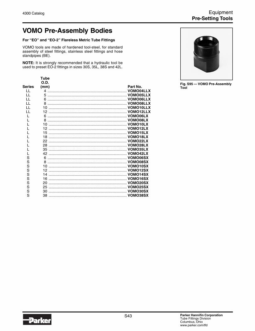
Parker Hannifin CorporationTube Fittings DivisionColumbus, Ohiowww.parker.com/tfd
S43
4300 Catalog Equipment
Fig. S95 — VOMO Pre-AssemblyTool
VOMO Pre-Assembly BodiesFor “EO” and “EO-2” Flareless Metric Tube Fittings
VOMO tools are made of hardened tool-steel, for standardassembly of steel fittings, stainless steel fittings and hosestandpipes (BE).
NOTE: It is strongly recommended that a hydraulic tool beused to preset EO-2 fittings in sizes 30S, 35L, 38S and 42L.
TubeO.D.
Series (mm) Part No.LL 4 ............................................................................ VOMO04LLXLL 5 ............................................................................ VOMO05LLXLL 6 ............................................................................ VOMO06LLXLL 8 ............................................................................ VOMO08LLXLL 10 ........................................................................... VOMO10LLXLL 12 ........................................................................... VOMO12LLXL 6 ............................................................................ VOMO06LXL 8 ............................................................................ VOMO08LXL 10 ........................................................................... VOMO10LXL 12 ........................................................................... VOMO12LXL 15 ........................................................................... VOMO15LXL 18 ........................................................................... VOMO18LXL 22 ........................................................................... VOMO22LXL 28 ........................................................................... VOMO28LXL 35 ........................................................................... VOMO35LXL 42 ........................................................................... VOMO42LXS 6 ............................................................................ VOMO06SXS 8 ............................................................................ VOMO08SXS 10 ........................................................................... VOMO10SXS 12 ........................................................................... VOMO12SXS 14 ........................................................................... VOMO14SXS 16 ........................................................................... VOMO16SXS 20 ........................................................................... VOMO20SXS 25 ........................................................................... VOMO25SXS 30 ........................................................................... VOMO30SXS 38 ........................................................................... VOMO38SX
Pre-Setting Tools

Parker Hannifin CorporationTube Fittings DivisionColumbus, Ohiowww.parker.com/tfd
S44
4300 Catalog Equipment
Fig. S96 — KONU Gauge
KONU Cone GaugesFor Pre-assembly Tools
For the dimensional control of cones in pre-assembly bodies(VOMO, MOS and MOK).
TubeSeries O.D. Part No.
LL 4 ............................................................................ KONU04+05LLXLL 5 ............................................................................ KONU04+05LLXLL 6 ............................................................................ KONU06+08LLXLL 8 ............................................................................ KONU06+08LLXLL 10 ........................................................................... KONU10+12LLXLL 12 ........................................................................... KONU10+12LLXL 6 ............................................................................ KONU06+08LX*L 8 ............................................................................ KONU06+08LX*L 10 ........................................................................... KONU10+12LX*L 12 ........................................................................... KONU10+12LX*L 15 ........................................................................... KONU15+18LXL 18 ........................................................................... KONU15+18LXL 22 ........................................................................... KONU22+28LXL 28 ........................................................................... KONU22+28LXL 35 ........................................................................... KONU35+42LXL 42 ........................................................................... KONU35+42LXS 6 ............................................................................ KONU06+08SX*S 8 ............................................................................ KONU06+08SX*S 10 ........................................................................... KONU10+12SX*S 12 ........................................................................... KONU10+12SX*S 14 ........................................................................... KONU14+16SXS 16 ........................................................................... KONU14+16SXS 20 ........................................................................... KONU20+25SXS 25 ........................................................................... KONU20+25SXS 30 ........................................................................... KONU30+38SXS 38 ........................................................................... KONU30+38SX
* Cone gauges for tube o.d. 6 to 12 are identical in series L and S.
Pre-Setting Tools

Parker Hannifin CorporationTube Fittings DivisionColumbus, Ohiowww.parker.com/tfd
S45
4300 Catalog Equipment
Fig. S97 — Hyferset
Fig. S98 — ElectricPump
Fig. S99 — Hand Pump
HyfersetHydraulic Parker Ferrule Pre-Setting Tool for Ferulok®
Fittings and EO/EO-2 Metric Fittings
PORTABLE...EFFICIENT...EASY TO USE
The Hyferset is an efficient, dependable device for pre-settingParker ferrules on tube of steel and stainless steel. This taskis made easy through hydraulic power provided by a hand orelectric pump. The equipment is portable and may be pro-cured in a sturdy wood carrying case.
In hydraulic pre-setting, little physical strength is required bythe operator to set ferrules properly. Although the amount offorce needed increases as the ferrule size increases, thepressure can be easily achieved.
This tool accommodates pre-setting dies for tubes ranging insize from 4 through 32 (1/4" through 2" outside diameter) and6mm to 28mm O.D. metric sizes. The tube, with tube nut andferrule, is positioned in the die. The hydraulic “push” of theHyferset pre-sets the ferrule onto the tube — producing avisible ridge of metal, in front of the sleeve bite edge, that canbe easily inspected.
Positive Stop Body Dies
The positive stop body die design eliminates the need forpredetermined relief valve settings, pressure gauges or chartreading. Positive stop feature allows for uniform assembliesto be made on tube from 1/4" thru 2". One set of dies can beused on steel and stainless steel tube. When used in conjunc-tion with the Ferulok visible bite ferrules, the entire system isthe most reliable method available for assembling a fitting toa piece of tube.
See page V10 for pre-setting pressures for EO and EO-2 steelfittings.
A VHS video is included to provide instructions for proper use.
COMPONENTS REQUIRED
Part Name Part No.Hyferset (basic unit, no accessories) ........................................ 611011AHyferset Adapter ........................................................................ 6 FLO-SGauge “T” Adapter ..................................................................... 6 R6LO-SHose Assembly .......................................................................... 910004Gauge Swivel Adapter ............................................................... 6 G6L-SPressure Gauge (0 - 10,000 psi) ............................................... 900044Hand pump (10,000 psi, 2 speed) ............................................. 900086Electric pump (10,000 psi, 1/2 HP, 40-125 volt) ........................ 900085Nut die set (1/4" to 2" O.D.) ........................................................ See page S46Positive Stop body die (1/4" to 2" O.D.) ..................................... See page S46Nut Die Set (6mm to 28mm) ....................................................... See page S47Body Die (6mm to 28mm)........................................................... See page S47
Pre-Setting Tools

Parker Hannifin CorporationTube Fittings DivisionColumbus, Ohiowww.parker.com/tfd
S46
4300 Catalog Equipment
Fig. S100 — Hyferset WoodCarrying Case
Fig. S101 — Hyferset Kit
OPTIONAL ACCESSORIES
Part Name Part No.Wooden carrying case ............................................................... 651085Operation Video ......................................................................... 4390-TFV
Part Name Part No.Hyferset Kit ................................................................................ 611049C
Includes basic unit, hand hydraulic pump, hoseassembly, 1 adapter (6 FLO-S), wooden carrying case,operation manual and video.
Hyferset Body Dies for Ferulok Fittings
Tube O.D.Size (in.) Part No.
4 1/4 ........................................................................... 720105-46 3/8 ........................................................................... 720105-68 1/2 ........................................................................... 720105-8
10 5/8 ........................................................................... 720105-1012 3/4 ........................................................................... 720105-1214 7/8 ........................................................................... 720105-1416 1 ............................................................................ 720105-1620 1 1/4 ......................................................................... 720105-2024 1 1/2 ......................................................................... 720105-2432 2 ............................................................................ 720105-32
Hyferset Nut Dies for Ferulok Fittings
Tube O.D.Size (in.) Part No.
4 1/4 ........................................................................... 680370-46 3/8 ........................................................................... 680370-68 1/2 ........................................................................... 680370-8
10 5/8 ........................................................................... 680370-1012 3/4 ........................................................................... 680370-1214 7/8 ........................................................................... 680370-1416 1 ............................................................................ 680370-1620 1 1/4 ......................................................................... 680370-2024 1 1/2 ......................................................................... 680370-2432 2 ............................................................................ 680370-32
Fig. S102 — Body Die
Fig. S103 — Nut Die
Pre-Setting Tools
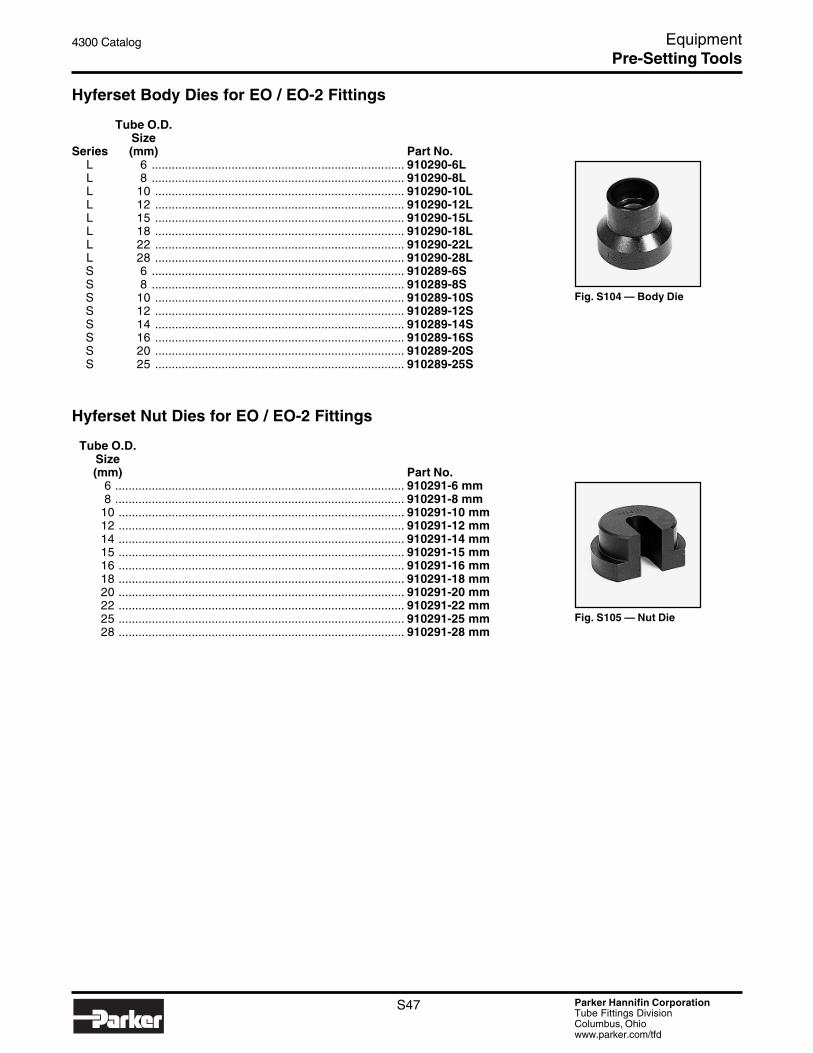
Parker Hannifin CorporationTube Fittings DivisionColumbus, Ohiowww.parker.com/tfd
S47
4300 Catalog Equipment
Hyferset Body Dies for EO / EO-2 Fittings
Tube O.D.Size
Series (mm) Part No.L 6 ............................................................................ 910290-6LL 8 ............................................................................ 910290-8LL 10 ........................................................................... 910290-10LL 12 ........................................................................... 910290-12LL 15 ........................................................................... 910290-15LL 18 ........................................................................... 910290-18LL 22 ........................................................................... 910290-22LL 28 ........................................................................... 910290-28LS 6 ............................................................................ 910289-6SS 8 ............................................................................ 910289-8SS 10 ........................................................................... 910289-10SS 12 ........................................................................... 910289-12SS 14 ........................................................................... 910289-14SS 16 ........................................................................... 910289-16SS 20 ........................................................................... 910289-20SS 25 ........................................................................... 910289-25S
Hyferset Nut Dies for EO / EO-2 Fittings
Tube O.D.Size(mm) Part No.
6 ....................................................................................... 910291-6 mm8 ....................................................................................... 910291-8 mm
10 ...................................................................................... 910291-10 mm12 ...................................................................................... 910291-12 mm14 ...................................................................................... 910291-14 mm15 ...................................................................................... 910291-15 mm16 ...................................................................................... 910291-16 mm18 ...................................................................................... 910291-18 mm20 ...................................................................................... 910291-20 mm22 ...................................................................................... 910291-22 mm25 ...................................................................................... 910291-25 mm28 ...................................................................................... 910291-28 mm
Fig. S104 — Body Die
Fig. S105 — Nut Die
Pre-Setting Tools

Parker Hannifin CorporationTube Fittings DivisionColumbus, Ohiowww.parker.com/tfd
S48
4300 Catalog Equipment
Fig. S106 — Ram Insert(Ferulok Only)
Fig. S107 — Small RamInsert and Stop Adapter(EO and EO-2 only)
Hydra-ToolPre-Setting Components
COMPONENTS REQUIRED
Part Name Part No.Hydra-Tool (basic unit) (Fig. S80) ............................................. 710400BHand pump (10,000 psi, 2 speed) ............................................. 900086Electric pump (10,000 PSI, 1/2 HP, 40-125 volt) ...................... 900085Hose Assembly .......................................................................... 910004Back-up Plate (sizes -4 to -32 and 6mm to 28mm) ................... 770102Back-up Plate (sizes 30 to 42mm) ............................................. See page S49Ram Insert (sizes -4 to -32) ....................................................... 770101Small Ram Insert (EO & EO-2 only) .......................................... 971108Large Piston Stop Adapter (EO & EO-2 only) ........................... 971107Nut die set (1/4" to 2" O.D.) ........................................................ See belowPositive Stop body die (1/4" to 2" O.D.) ..................................... See belowNut Die Set (6mm to 42mm) ....................................................... See page S49Body Die (6mm to 42mm)........................................................... See page S49Pressure Gauge (0 - 10,000 psi) ............................................... 900044Male Adapter ............................................................................. 6-8 F5OLO-SAdapter ...................................................................................... 6 G6L-SHydra-Tool Gauge Adapter ........................................................ 6 R6LO-S
See Appendix for pre-setting pressures.
Hydra-Tool Body Dies for Ferulok Fittings
Tube O.D.Size (in.) Part No.
4 1/4 ........................................................................... 720105-46 3/8 ........................................................................... 720105-68 1/2 ........................................................................... 720105-8
10 5/8 ........................................................................... 720105-1012 3/4 ........................................................................... 720105-1214 7/8 ........................................................................... 720105-1416 1 ............................................................................ 720105-1620 1 1/4 ......................................................................... 720105-2024 1 1/2 ......................................................................... 720105-2432 2 ............................................................................ 720105-32
Hydra-Tool Nut Dies for Ferulok Fittings
Tube O.D.Size (in.) Part No.
4 1/4 ........................................................................... 680370-46 3/8 ........................................................................... 680370-68 1/2 ........................................................................... 680370-8
10 5/8 ........................................................................... 680370-1012 3/4 ........................................................................... 680370-1214 7/8 ........................................................................... 680370-1416 1 ............................................................................ 680370-1620 1 1/4 ......................................................................... 680370-2024 1 1/2 ......................................................................... 680370-2432 2 ............................................................................ 680370-32
Fig. S108 — Body Die
Fig. S109 — Nut Die Set
Pre-Setting Tools

Parker Hannifin CorporationTube Fittings DivisionColumbus, Ohiowww.parker.com/tfd
S49
4300 Catalog Equipment
Fig. S110 — Body Die
Fig. S112 — Nut Die Set
Fig. S111 — Back-upPlates
Hydra-Tool Body Dies for EO / EO-2 Fittings
Tube O.D.Size
Series (mm) Part No.L 6 ............................................................................ 910290-6LL 8 ............................................................................ 910290-8LL 10 ........................................................................... 910290-10LL 12 ........................................................................... 910290-12LL 15 ........................................................................... 910290-15LL 18 ........................................................................... 910290-18LL 22 ........................................................................... 910290-22LL 28 ........................................................................... 910290-28LL 35 ........................................................................... 910290-35LL 42 ........................................................................... 910290-42LS 6 ............................................................................ 910289-6SS 8 ............................................................................ 910289-8SS 10 ........................................................................... 910289-10SS 12 ........................................................................... 910289-12SS 14 ........................................................................... 910289-14SS 16 ........................................................................... 910289-16SS 20 ........................................................................... 910289-20SS 25 ........................................................................... 910289-25SS 30 ........................................................................... 910289-30SS 38 ........................................................................... 910289-38S
Hydra-Tool Nut Die / Split Back-up PlateSets for EO / EO-2 Fittings
Tube O.D.Size(mm) Part No.
6 ....................................................................................... 910291-6 mm8 ....................................................................................... 910291-8 mm
10 ...................................................................................... 910291-10 mm12 ...................................................................................... 910291-12 mm14 ...................................................................................... 910291-14 mm15 ...................................................................................... 910291-15 mm16 ...................................................................................... 910291-16 mm18 ...................................................................................... 910291-18 mm20 ...................................................................................... 910291-20 mm22 ...................................................................................... 910291-22 mm25 ...................................................................................... 910291-25 mm28 ...................................................................................... 910291-28 mm30 ...................................................................................... 970135-30 mm35 ...................................................................................... 970135-35 mm38 ...................................................................................... 970135-38 mm42 ...................................................................................... 970135-42 mm
Pre-Setting Tools

Parker Hannifin CorporationTube Fittings DivisionColumbus, Ohiowww.parker.com/tfd
S50
4300 Catalog Equipment
Fig. S113 — HVMKPLX
HVMB Pre-Assembly ToolFor “EO” Flareless Metric Tube Fittings
Part No.HVMBKPLX
This pre-installation tool is a simple appliance for a quick andsafe pre-installation of EO-progressive rings. The tool is veryhandy and can be taken to any site provided a vise isavailable. Suitable for LL, L and S series and tube sizes from4 to 18mm O.D.
Weight: Approx. 7.9 kg without tools (approx. 17.5 lbs.)
Tube Location Plates (2 required)
Tube O.D.Series (mm) Part No.
LL 4 ............................................................................ HL04XLL 5 ............................................................................ HL05XLL 6 ............................................................................ HL06XLL 8 ............................................................................ HL08XLL 10 ........................................................................... HL10XLL 12 ........................................................................... HL12XL 6 ............................................................................ HL06XL 8 ............................................................................ HL08XL 10 ........................................................................... HL10XL 12 ........................................................................... HL12XL 15 ........................................................................... HL15XL 18 ........................................................................... HL18XS 6 ............................................................................ HL06XS 8 ............................................................................ HL08XS 10 ........................................................................... HL10XS 12 ........................................................................... HL12XS 14 ........................................................................... HL14XS 16 ........................................................................... HL16X
Assembly Cones
Tube O.D.Series (mm) Part No.
LL 4 ............................................................................ MOSI04LLXLL 5 ............................................................................ MOSI05LLXLL 6 ............................................................................ MOSI06LLXLL 8 ............................................................................ MOSI08LLXLL 10 ........................................................................... MOSI10LLXLL 12 ........................................................................... MOSI12LLXL 6 ............................................................................ MOSI60LXL 8 ............................................................................ MOSI08LXL 10 ........................................................................... MOSI10LXL 12 ........................................................................... MOSI12LXL 15 ........................................................................... MOSI15LXL 18 ........................................................................... MOSI18LXS 6 ............................................................................ MOSI06SXS 8 ............................................................................ MOSI08SXS 10 ........................................................................... MOSI10SXS 12 ........................................................................... MOSI12SXS 14 ........................................................................... MOSI14SXS 16 ........................................................................... MOSI16SX
Pre-Setting Tools

Parker Hannifin CorporationTube Fittings DivisionColumbus, Ohiowww.parker.com/tfd
S51
4300 Catalog Equipment
Fig. S114 — EO-Karrymat
EO-KarrymatPart No.EO-Karrymat
The EO-Karrymat is a dependable device for safe and effi-cient bite-type pre-setting. It allows pre-assembly of all sizesof EO, EO-2 and Ferulok fittings without the need for electricpower.
The EO-Karrymat consists of a hydraulic drive, Handpumpand pressure gauge, all firmly attached to a carrying case.
EO-Karrymat Body Dies for EO / EO-2 Fittings
Tube O.D.Series (mm) Part No.
LL 4 ............................................................................ MOK04LLXLL 6 ............................................................................ MOK06LLXLL 8 ............................................................................ MOK08LLXLL 10 ........................................................................... MOK10LLXLL 12 ........................................................................... MOK12LLXL 6 ............................................................................ MOK06LXL 8 ............................................................................ MOK08LXL 10 ........................................................................... MOK10LXL 12 ........................................................................... MOK12LXL 15 ........................................................................... MOK15LXL 18 ........................................................................... MOK18LXL 22 ........................................................................... MOK22LXL 28 ........................................................................... MOK28LXL 35 ........................................................................... MOK35LXL 42 ........................................................................... MOK42LXS 6 ............................................................................ MOK06SXS 8 ............................................................................ MOK08SXS 10 ........................................................................... MOK10SXS 12 ........................................................................... MOK12SXS 14 ........................................................................... MOK14SXS 16 ........................................................................... MOK16SXS 20 ........................................................................... MOK20SXS 25 ........................................................................... MOK25SXS 30 ........................................................................... MOK30SXS 38 ........................................................................... MOK38SX
Fig. S115 — MOK Body Die
Pre-Setting Tools

Parker Hannifin CorporationTube Fittings DivisionColumbus, Ohiowww.parker.com/tfd
S52
4300 Catalog Equipment
Fig. S116 — GHP Nut Die
EO-Karrymat Nut Dies for EO / EO-2 Fittings
Tube O.D.Series (mm) Part No.
LL 4 ............................................................................ GHP04XLL 6 ............................................................................ GHP06X*LL 8 ............................................................................ GHP08X*LL 10 ........................................................................... GHP10X*LL 12 ........................................................................... GHP12X*L 6 ............................................................................ GHP06X*L 8 ............................................................................ GHP08X*L 10 ........................................................................... GHP10X*L 12 ........................................................................... GHP12X*L 15 ........................................................................... GHP15XL 18 ........................................................................... GHP18XL 22 ........................................................................... GHP22XL 28 ........................................................................... GHP28XL 35 ........................................................................... GHP35XL 42 ........................................................................... GHP42XS 6 ............................................................................ GHP06X*S 8 ............................................................................ GHP08X*S 10 ........................................................................... GHP10X*S 12 ........................................................................... GHP12X*S 14 ........................................................................... GHP14XS 16 ........................................................................... GHP16XS 20 ........................................................................... GHP20XS 25 ........................................................................... GHP25XS 30 ........................................................................... GHP30XS 38 ........................................................................... GHP38X
* Nut Dies for 6-12mm are identical in LL, L and S series.
EO-Karrymat Body Dies for Ferulok Fittings
Tube Size(in.) Part No.1/4 ........................................................................................ 976521-43/8 ........................................................................................ 976521-61/2 ........................................................................................ 976521-85/8 ........................................................................................ 976521-103/4 ........................................................................................ 976521-121 .......................................................................................... 976521-16
1 1/4 ....................................................................................... 976521-201 1/2 ....................................................................................... 976521-24
2 .......................................................................................... 976521-32
EO-Karrymat Back-up Plates for FerulokFittings
Tube Size(in.) Part No.1/4 ........................................................................................ 975867-43/8 ........................................................................................ 975867-61/2 ........................................................................................ 975867-85/8 ........................................................................................ 975867-103/4 ........................................................................................ 975867-121 .......................................................................................... 975867-16
1 1/4 ....................................................................................... 975867-201 1/2 ....................................................................................... 975867-24
2 .......................................................................................... 975867-32
Fig. S117 — EO-KarrymatBody Dies for Ferulok
Fig. S118 — EO-KarrymatBack-up Plates for Ferulok
Pre-Setting Tools

Parker Hannifin CorporationTube Fittings DivisionColumbus, Ohiowww.parker.com/tfd
S53
4300 Catalog Equipment
Fig. S119 — EOMAT IIIA
Fig. S120 — ToolCompartment (toolingshown, but not included)
Fig. S122 — Foot Pedal Switch
Fig. S121 — AssemblyFixture
EOMAT IIIPre-Setting Machine for EO and EO-2 Fittings
The EOMAT III is an electronically controlled hydraulic driveunit for pre-assembly of cutting rings for both EO and EO-2fittings. It can be utilized with steel and stainless steel tubewith an outer diameter of 6mm through 42mm. The requiredoperating pressure depends on the tube type, material andtube dimensions, and is automatically selected by a micropro-cessor. The EOMAT III is available with 440V/60Hz.
For additional technical information, please see Catalog 4303-GB.
DIMENSIONS: W – 27.17" H – 12.6" D – 20.87"
COMPONENTS REQUIRED
Part Name Part No.EOMAT III .................................................................................. EOMATIII/A440V60HZXAssembly Fixture (pre-setting) ................................................... EOMATSCHNEIDRXFixture for Flaring ....................................................................... EOMATBOERDELBXBody Die .................................................................................... See page S51Nut Die ....................................................................................... See page S52
OPTIONAL ACCESSORIES
Part Name Part No.Foot Pedal Switch ...................................................................... EOMATIIIFUSSXTool Compartment ..................................................................... EOMATWERKZGAUFN.X
Pre-Setting Tools

Parker Hannifin CorporationTube Fittings DivisionColumbus, Ohiowww.parker.com/tfd
S54
4300 Catalog Equipment
Fig. S124 — O-Ring InstallationKit
O-Ring PickPart No.O-Ring Pick
Plastic O-ring pick allows for easy removal of O-rings withoutcausing damage to the fitting.
O-Ring Installation KitPart No.890033
Parker’s O-ring Installation Kit contains a complete set of toolsfor installing Parker O-rings ranging in size from size 3-902through 3-932. Easy-to-follow instructions permit the properfit the first time.
Each tool is sized to allow easy installation, while preventingdamage to the O-ring as it is passing over the threads. Goodfor determining the size of O-rings as well.
O-ring installation tools are not sold separately.
O-rings are not included in this kit.
NSN-5120-01-319-0786
Captive O-Ring Assembly ToolThe captive O-ring (CORG) assembly tool utilizes a Parkerpatented method for inserting O-rings in ORFS fittings, suchas Seal-Lok, without causing O-ring damage. These tools canbe used both as a hand tool and a bench-mounted tool. AllCORG tools have a #8-32 tapped hole to allow easy mount-ing.
Fitting L D1 D2 O-RingSize (in.) (in.) (in.) Size Part No.
-4 1.4 0.8 0.6 2-011 ............ CORG-4-6 1.5 0.9 0.6 2-012 ............ CORG-6-8 1.5 1.1 0.8 2-014 ............ CORG-8
-10 1.6 1.3 0.9 2-016 ............ CORG-10-12 1.9 1.4 1.1 2-018 ............ CORG-12-16 1.9 1.7 1.3 2-021 ............ CORG-16-20 2.1 1.9 1.6 2-025 ............ CORG-20-24 2.1 2.3 1.9 2-029 ............ CORG-24-32 2.2 2.8 2.4 2-135 ............ CORG-32
Fig. S125 — Captive O-RingAssembly Tool
Fig. S123 — O-Ring Pick
Fig. S126 — Captive O-RingAssembly Tool dimensions
L
D2 D1
O-Ring Assembly Tools

Parker Hannifin CorporationTube Fittings DivisionColumbus, Ohiowww.parker.com/tfd
S55
4300 Catalog Equipment
Fig. S127 — Safety Glasses
Fig. S128 — LensCleaning Towels
Fig. S129 — Counter Display
Safety Eyewear and AccessoriesParker safety eyewear by Crews® meet or exceed ANSIZ87.1standards where applicable. The offering includes five stylesof safety eyewear, cleaning products, displays and eyewearstraps.
Part Description Part No.Safety GlassesTomahawk, black frame, clear a/f lens, Parker logo ................. TK110AF-PStorm, black frame, clear lens ................................................... ST110Blackjack, chrome frame, indoor/outdoor lens .......................... S2119Excaliber, black frame, clear lens, Parker logo ......................... 99910-PFrostbite2, blue frost frame, grey lens ....................................... F2122
AccessoriesBlack eyeglass strap .................................................................. 215-StrapBlue eyeglass strap ................................................................... 216-StrapIndividual lens cleaning towels, 100 count ................................ LCT-1Counter display, holds 12 pairs, swivel base ............................ ED-12Wall display, holds 18 pairs ....................................................... HD-18
Fig. S130 — Wall Display
Safety Eyewear & Accessories

Parker Hannifin CorporationTube Fittings DivisionColumbus, Ohiowww.parker.com/tfd
S56
4300 Catalog Equipment
Fig. S131 — ParflangeLubricants, LB 2000 andMPG-2
Fig. S133 — EO Niromont
Fig. S134 — Loctite Anti-SeizeLubricant
Fig. S132 — STP Lubricant
LubricantsLubricants act as friction reducers to ease forming processes,fitting assembly and prevent galling, corrosion and seizing ofcomponents. The use of the correct lubricant for variouspurposes is critical to achieve maximum tool life during form-ing processes and performance of threaded connections.
Parflange® Lubricants
Lubricants are used to maximize tool life during the flangingprocess. Selection of the appropriate lubricant for the type ofParflange machine is critical to its proper operation.
Part Description Part No.Recommended for use with steel or stainless steel .................. LB 2000 (8 oz.)Recommended for use with carbon steel only .......................... MPG-2 Grease/1030
Flaring and Presetting Lubricants
High pressure lubricant is necessary to maximize tool life andassure flare/preset quality during the associated processes.STP lubricant is recommended for lubrication of all presettingtools and for the flaring tooling associated with the Hydra-Tooland 1015 machines.
Part Description Part No.Flaring and Presetting Lubricant ............................................... STP
EO / EO-2 Fitting Lubricants
EO Niromont lubricants are specifically developed for lubrica-tion of threads prior to assembly of EO and EO-2 fittings.
Part Description Part No.EO Niromont – Liquid 250cc bottle ............................................ Niromont-LiquidEO Niromont – Paste 130 g. tin ................................................. Niromont-Paste
Loctite Anti-Seize Lubricant
This highly refined blend of aluminum, copper and graphitelubricant is designed for use during assembly of threadedcomponents to prevent galling, corrosion and seizing in tem-peratures of -65°F to +1600°F. This lubricant also assureseasier assembly. The lubricant is salt-, corrosion- and mois-ture-resistant. Applications: Stainless steel threads for re-duced chance of galling.
Part Description Part No.4 oz. Tube, Brush Top ............................................................... 802098 oz. Bottle, Brush Top .............................................................. 7673213 oz. Aerosol ............................................................................ 767598 oz. Bottle, Marine Grade ......................................................... 3439516 oz. Bottle, Marine Grade ....................................................... 34026
Sealants, Lubricants & Cleaners

Parker Hannifin CorporationTube Fittings DivisionColumbus, Ohiowww.parker.com/tfd
S57
4300 Catalog Equipment
Super-Lube® PTFE Grease
Super-Lube® is developed for lubricating against friction andwear of mating components. It withstands temperatures rang-ing from -45°F to +450°F.
Part Description Part No.Super-Lube® 11 oz. Aerosol ...................................................... 20029
Loctite Penetrating Oil
This product penetrates, lubricates and displaces moisture inmating components. Loctite Penetrating Oil also protectsagainst rust and corrosion.
Part Description Part No.16 oz. Aerosol ............................................................................ 51221
Fig. S135 —Super-Lube
Fig. S136 — LoctitePenetrating Oil
Fig. S137 — Parker O-Lube
Fig. S138 — ParkerSuper O-Lube
O-Ring LubricantsParker O-Lube
O-Lube is an outstanding general-purpose grease intendedfor use with O-rings and other seals in hydraulic and pneu-matic systems. The temperature range is from -29°C to +82°C(-20°F to +180°F).
Part Description Part No.O-ring Lubricant ......................................................................... OLUBE-884-4-TFD
Parker Super O-Lube
Super O-Lube is an all-purpose O-ring lubricant. It is not agrease, but rather a high-viscosity silicone oil. The tempera-ture range is -54°C to +204°C (-65°F to +400°F).
Part Description Part No.O-ring Lubricant ......................................................................... SLUBE-884-2-TFD
Sealants, Lubricants & Cleaners

Parker Hannifin CorporationTube Fittings DivisionColumbus, Ohiowww.parker.com/tfd
S58
4300 Catalog Equipment
Fig. S141 — LoctiteThread Sealant 545
Thread SealantsThread sealants seal and secure metal pipes and fittings byfilling the space between the threaded metal parts. Threadsealants harden to prevent leakage caused by vibrationloosening, solvent evaporation, damaged threads and tem-perature cycling. Designed for low and high pressure applica-tions, thread sealants seal quickly for on-line low pressuretesting. When fully cured, they seal to the burst strength ofmost systems. Thread sealants are easily remove with basichand tools. Thread sealants can be used on pipe threadfittings.
Threadmate™ Sealant/Lubricant
Threadmate™ is an extreme-duty lubricant developed toreduce galling during the assembly of pipe thread fittings.Threadmate™ promotes reliable sealing of pipe threads,even at high pressure. Recommended for use on stainlesssteel pipe threads.
Size available Part No.4 oz. tube ................................................................................... MTM04T-TFD
Loctite Thread Sealant 567
Formulated specifically for metal tapered pipe thread fittings.PST 567 cures rapidly to provide immediate low pressuresealing. Its controlled lubricity prevents galling and it protectsmated thread areas from rust and corrosion. Performs intemperatures ranging from -65°F to +44°F. Application: Stain-less steel tapered pipe threads.
Part Description Part No.6 ml Tube ................................................................................... 5670750 ml Tube ................................................................................. 56747
Loctite Thread Sealant 545
Designed for both hydraulic and pneumatic systems, 545contains no fillers or particles which could contaminate sys-tem fluids, foul valves, or clog fine filters and screens. Appli-cations: Steel and brass tapered pipe threads. Temperaturerange: -65°F to +300°F.
Part Description Part No..5 ml Capsule ............................................................................. 5450550 ml Bottle ................................................................................ 54531
Fig. S139 — ThreadmateSealant/Lubricant
Fig. S140 — LoctiteThread Sealant 567
Sealants, Lubricants & Cleaners

Parker Hannifin CorporationTube Fittings DivisionColumbus, Ohiowww.parker.com/tfd
S59
4300 Catalog Equipment
Pipe Thread Sealing Cord
Loctite 55 Pipe Sealing Cord is a general purpose threadedpipe sealant. It is a non-curing, coated multifilament cord thatseals fluids and gases in pipe threads up to 4". Sealanttemperature ranges from -65°F to +300°F.
Part Description Part No.Pipe Thread Sealing Cord, 5,700 in. ......................................... 35082
Thread Sealant Tape
Part Description Part No.1/2" x 520" Spools ..................................................................... PTFE Tape
ThreadlockersThread lockers perform by filling the space between threadedmetal parts and hardening to form a tough, adhesive bondand seal. Threadlockers seal the threads against leakageand prevent rust and corrosion. Threadlockers can be usedon fasteners. Some threadlockers require extra effort orspecial tools for removal.
Loctite Primer N
Loctite 7649 Primer N decreases the set-up time of Loctitethreadlockers and increases breakaway torque on most fas-tener surfaces. It allows for cold weather application. Applica-tions: Use with Loctite threadlockers, thread sealants andretaining compounds.
Part Description Part No.25 g Aerosol ............................................................................... 213474.5 oz. Aeorosol ......................................................................... 21348
Threadlocker 242
All-purpose, medium strength threadlocker is ideal for all nutand bolt applications. It eliminates the need for stockingexpensive locknuts and washers. Its other advantages in-clude locking and sealing while preventing parts looseningduring vibration, protecting threads from corrosion, and easydisassembly with hand tools. Applications: All fastener appli-cations. Temperature range: -65°F to +300°F.
Part Description Part No.10 ml Tube ................................................................................. 2422150 ml Tube ................................................................................. 24231
Fig. S144 — Loctite 7649Primer N
Fig. S143 — PTFE Tape
Fig. S142 — Pipe ThreadSealing Cord
Fig. S145 — LoctiteThreadlocker 242
Sealants, Lubricants & Cleaners

Parker Hannifin CorporationTube Fittings DivisionColumbus, Ohiowww.parker.com/tfd
S60
4300 Catalog Equipment
Loctite High Strength Threadlocker 271
High strength threadlocker for heavy-duty applications isespecially well-suited for permanently locking studs and pressfits. It replaces set screw and snap rings and locks againstvibration loosening. Applications: Permanent fastener re-quirements. Temperature range: -65°F to +300°F. DO NOTUSE THIS PRODUCT WITH PARKER TUBE FITTINGS.RECOMMENDED ONLY FOR FASTENER APPLICATIONS.
Part Description Part No.10 ml Tube ................................................................................. 2712150 ml Tube ................................................................................. 27131
CleanersLoctite cleaners and degreasers are designed for variousapplications to remove grease, grime, paint, adhesives andother soils your working hands get into. Fast Orange handcleaners have aded conditioners to prevent your hands fromcracking and drying out.
Loctite Fast Orange Hand Cleaner
Fast Orange is the #1 selling biodegradable, waterless petro-leum solvent-free hand cleaner that contains no harsh chemi-cals, mineral oils or ammonia that can sting cuts and abra-sions. Pure, fresh smelling natural citrus power does thecleaning. With aloe, lanolin, jojoba, and now Corn HuskersLotion® for added skin conditioning and protection, its smoothformula gently deep cleans the toughest dirt. Applications:Clean-up of resins, oil, grease, tar, ink, epoxies, paint andvarious adhesives.
Part Description Part No.15 oz. Bottle ............................................................................... 251161 Gallon with Pump .................................................................... 25218Industrial Hand Wipes, 75 count ............................................... 34943
Loctite Natural Blue® Degreaser
This biodegradable, all-purpose, industrial strength, concen-trated cleaner and degreaser can be easily diluted with waterfor use in a variety of cleaning applications. Non-flammableand non-toxic.
Part Description Part No.24 oz. Spray Bottle .................................................................... 822491 Gallon Concentrate ................................................................. 82251
Fig. S146 — Loctite HighStrength Threadlocker 271
Fig. S147 — Loctite Fast OrangeHand Cleaner
Fig. S148 — Loctite NaturalBlue® Degreaser
Sealants, Lubricants & Cleaners

Parker Hannifin CorporationTube Fittings DivisionColumbus, Ohiowww.parker.com/tfd
S61
4300 Catalog Equipment
Loctite Pro Strength Parts Cleaner
This product was developed to aggressively penetrate, dis-solve and remove oil and grease from parts. Dries quickly withno residue.
Part Description Part No.19 oz. Aerosol ............................................................................ 30548
Loctite Rack
Parker’s Loctite Rack makes a convenient counter top displayfor Loctite products. No supplies included.
Part Description Part No.Loctite Product Rack ................................................................. RACK
Fig. S150 — Loctite Rack(Supplies not included)
Fig. S149 — Loctite ProStrength Parts Cleaner
Sealants, Lubricants & Cleaners

Parker Hannifin CorporationTube Fittings DivisionColumbus, Ohiowww.parker.com/tfd
S62
4300 Catalog Equipment
Fig. S151 — Tube PreparationCenter TP1025
Tube Preparation CentersParker offers five different styles of tube preparation centers tomeet various user’s needs, from the basic TP-1 unit whichincludes a cabinet and deburr unit, to the TP1025 which offersthe ability to cut, deburr, Parflange and flare tube.
Utilizing a sturdy steel cabinet with bins for fitting storage,tooling shelves and heavy duty casters to ease mobility,Parker Tube Preparation Centers cover almost every tubepreparation need. All machines require 110V, 20A powersupply.
Part Description Part No.Tube Prep Center with Deburr Unit ........................................... TP-1Tube Prep Center with Deburr and Saw ................................... TP-974250Tube Prep Center with Deburr, Saw and Hydratool .................. TP432Tube Prep Center with Deburr, Saw and Hyferset .................... TP-611011ATube Prep Center with Deburr, Saw and 1015 Flare Tool ........ TP-1015Tube Prep Center with Deburr, Saw and 1025 Parflange ........ TP1025
Replacement Parts Part No.I.D. Deburr Cone ........................................................................ 971816O.D. Deburr Blades (set of 6) .................................................... 910485Cutting Lubricant ........................................................................ Saw LubeSaw Blade – 8" x 200 tooth (all purpose material) .................... 4B14465-200Saw Blade – 8" x 200 tooth (for 1/4" - 1-1/2" SS) ...................... 972285Saw Blade – 10" x 240 tooth (for 1" and smaller SS and steel) 974581Saw Blade – 10" x 180 tooth (all purpose, 3/4" and smaller) .... 975685Saw Blade – 10" x 110 tooth
(structural material & tube over 2") ..................................... 979552Flaring tooling for TP432 ............................................................ See page S33 - S35Presetting tooling for TP432 and TP-Hyferset ............................ See page S45 - S49Flaring tooling for TP-1015 ......................................................... See page S36Flanging tooling for TP1025 ........................................................ See page S29Flaring tooling for TP1025 ........................................................... See page S37Lubricant for TP432 / TP-Hyferset ............................................. STPLubricant for TP1025 ................................................................. LB 2000
Tube Preparation Centers

Parker Hannifin CorporationTube Fittings DivisionColumbus, Ohiowww.parker.com/tfd
S63
4300 Catalog Equipment
Fig. S152 — Thread IdentificationKit
Thread Identification KitPart No.MIK-1
The Thread Identification Kit can be used to identify metric,BSP, SAE and NPT threads, as well as SAE flanges. It con-tains thread gauges, calipers, thread profiles, and an instruc-tion booklet that details most thread forms and connectionstyles found in fluidpower systems worldwide.
PortboardsThe Portboards can be used for identification of ISO, SAE,BSP and NPT ports and port threads. They are machined withfemale threads for quick and easy identification by screwingin the male port end.
Part No.Portboard A
Portboard A (SAE Straight Thread -2 through -32 and NPT1/8 through 1 1/2).
Part No.Portboard B
Portboard B (Metric 8mm through 48mm and BSP 1/8 through1 1/2).
Fig. S153 — Portboard A
Fig. S154 — Portboard B
Fig. S155 — International ThreadKit (ITK)
Part No. ITK
Parker’s International Thread Kit offers the necessary tools toidentify almost any thread you may encounter. The new ITKhas LL, L and S series plugs to identify female DIN threadssuch as EO style hose ends. It also includes the MIK-1 andBSPP plugs in order to identify BSPP hose ends from 1/8" to2".
Thread Idnetification
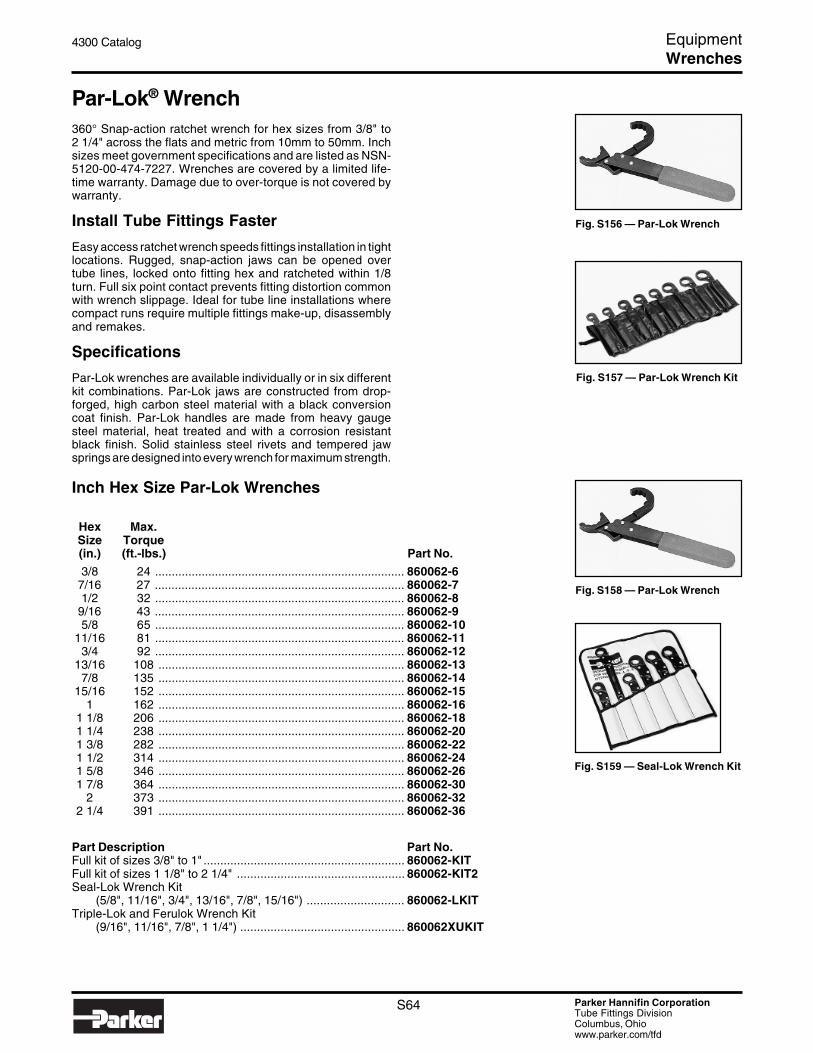
Parker Hannifin CorporationTube Fittings DivisionColumbus, Ohiowww.parker.com/tfd
S64
4300 Catalog Equipment
Inch Hex Size Par-Lok Wrenches
Hex Max.Size Torque(in.) (ft.-lbs.) Part No.
3/8 24 ........................................................................... 860062-67/16 27 ........................................................................... 860062-71/2 32 ........................................................................... 860062-8
9/16 43 ........................................................................... 860062-95/8 65 ........................................................................... 860062-10
11/16 81 ........................................................................... 860062-113/4 92 ........................................................................... 860062-12
13/16 108 .......................................................................... 860062-137/8 135 .......................................................................... 860062-14
15/16 152 .......................................................................... 860062-151 162 .......................................................................... 860062-16
1 1/8 206 .......................................................................... 860062-181 1/4 238 .......................................................................... 860062-201 3/8 282 .......................................................................... 860062-221 1/2 314 .......................................................................... 860062-241 5/8 346 .......................................................................... 860062-261 7/8 364 .......................................................................... 860062-30
2 373 .......................................................................... 860062-322 1/4 391 .......................................................................... 860062-36
Part Description Part No.Full kit of sizes 3/8" to 1" ............................................................ 860062-KITFull kit of sizes 1 1/8" to 2 1/4" .................................................. 860062-KIT2Seal-Lok Wrench Kit
(5/8", 11/16", 3/4", 13/16", 7/8", 15/16") ............................. 860062-LKITTriple-Lok and Ferulok Wrench Kit
(9/16", 11/16", 7/8", 1 1/4") ................................................. 860062XUKIT
Fig. S158 — Par-Lok Wrench
Fig. S159 — Seal-Lok Wrench Kit
Fig. S156 — Par-Lok Wrench
Fig. S157 — Par-Lok Wrench Kit
Par-Lok® Wrench360° Snap-action ratchet wrench for hex sizes from 3/8" to2 1/4" across the flats and metric from 10mm to 50mm. Inchsizes meet government specifications and are listed as NSN-5120-00-474-7227. Wrenches are covered by a limited life-time warranty. Damage due to over-torque is not covered bywarranty.
Install Tube Fittings Faster
Easy access ratchet wrench speeds fittings installation in tightlocations. Rugged, snap-action jaws can be opened overtube lines, locked onto fitting hex and ratcheted within 1/8turn. Full six point contact prevents fitting distortion commonwith wrench slippage. Ideal for tube line installations wherecompact runs require multiple fittings make-up, disassemblyand remakes.
Specifications
Par-Lok wrenches are available individually or in six differentkit combinations. Par-Lok jaws are constructed from drop-forged, high carbon steel material with a black conversioncoat finish. Par-Lok handles are made from heavy gaugesteel material, heat treated and with a corrosion resistantblack finish. Solid stainless steel rivets and tempered jawsprings are designed into every wrench for maximum strength.
Wrenches

Parker Hannifin CorporationTube Fittings DivisionColumbus, Ohiowww.parker.com/tfd
S65
4300 Catalog Equipment
Fig. S161 — Par-Lok Wrench Kit
Metric Hex Size Par-Lok Wrenches
Hex Max. Max.Size Torque Torque(mm) (ft.-lbs.) (N-m) Part No.
10 26 35 ....................................... 860063-1011 27 37 ....................................... 860063-1112 31 42 ....................................... 860063-1213 33 45 ....................................... 860063-1314 42 57 ....................................... 860063-1416 65 88 ....................................... 860063-1617 79 107 ...................................... 860063-1719 92 125 ...................................... 860063-1921 110 149 ...................................... 860063-2122 131 178 ...................................... 860063-2224 154 209 ...................................... 860063-2427 74 100 ...................................... 860063-2730 74 100 ...................................... 860063-3032 125 170 ...................................... 860063-3236 125 170 ...................................... 860063-3641 229 310 ...................................... 860063-4146 243 330 ...................................... 860063-4650 243 330 ...................................... 860063-50
Part Description Part No.Full kit of sizes 10mm to 22mm ................................................. 860063-KITFull kit of sizes 27mm to 50mm ................................................. 860063-KIT2
Fig. S160 — Triple-Lok andFerulok Wrench Kit
Wrenches
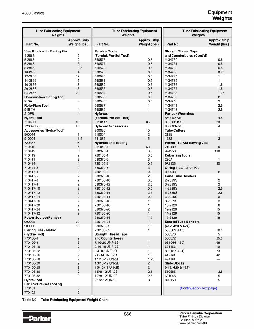
Parker Hannifin CorporationTube Fittings DivisionColumbus, Ohiowww.parker.com/tfd
S66
4300 Catalog Equipment
Tube Fabricating EquipmentWeights
Approx. ShipPart No. Weight (lbs.)
Straight Thread Tapsand Counterbores (Cont'd)Y-34730 0.5Y-34731 0.5Y-34732 0.5Y-34733 0.75Y-34734 1Y-34735 1Y-34736 1.5Y-34737 1.5Y-34738 1.75Y-34739 2Y-34740 2Y-34741 2.5Y-34743 2.5Par-Lok Wrenches860062-Kit 4.5860062-Kit 2 28860063-Kit 4Tube Cutters218B 11232 3Parker Tru-Kut Sawing Vise710439 9974250 198Deburring Tools226A 1972125 90O-ring Installation Kit890033 2Hand Tube Benders2-2829S 23-2829S 24-2829S 2.55-2829S 2.56-2829S 38-2829S 310-2829 812-2829 1514-2829 1516-2829 16Exactol Tube Benders(412, 420 & 424)560569 (412) 18.5550570 5550572 25.5621044 (420) 68631156 10890127 (424) 73412 Kit 42424 Kit —Slide Blocks(412, 420 & 424)550585 3.5621045 5870150 5
(Continued on next page)
Tube Fabricating EquipmentWeights
Approx. ShipPart No. Weight (lbs.)
Ferulset Tools(Ferulok Pre-Set Tool)560576 0.5560577 0.5560578 0.5560579 0.5560580 0.5560581 0.5560582 0.5560583 0.5560584 0.5560585 0.5560586 0.5560587 1560589 1Hyferset(Ferulok Pre-Set Tool)611011A 35Hyferset Accessories900086 10910004 2651085 15Hyferset and Tooling611049C 53680370-4 3.5720105-4 0.5680370-6 3720105-6 0.5680370-8 3720105-8 0.5680370-10 2.5720105-10 0.5680370-12 2.5720105-12 0.5680370-14 2.5720105-14 0.5680370-16 1.5720105-16 1680370-20 2720105-20 1680370-24 1.5720105-24 1680370-32 1.5720105-32 1Straight Thread Tapsand Counterbores7/16-20 UNF-2B 19/16-18 UNF-2B 13/4-16 UNF-2B 17/8-14 UNF-2B 1.51 1/16-12 UN-2B 1.751 3/16-12 UN-2B 21 5/16-12 UN-2B 21 5/8-12 UN-2B 2.51 7/8-12 UN-2B 2.52 1/2-12 UN-2B 3
Table N9 — Tube Fabricating Equipment Weight Chart
Tube Fabricating EquipmentWeights
Approx. ShipPart No. Weight (lbs.)
Vise Block with Flaring Pin4-2866 25-2866 26-2866 38-2866 3.510-2866 412-2866 1214-2866 1516-2866 1820-2866 1824-2866 20Combination Flaring Tool210A 3Rolo-Flare Tool945 TH 4212FB 4Hydra-Tool710400B 62720370B-3 85Accessories (Hydra-Tool)900044 1910004 1.5720377 16710416 4710412 3710419 2710411 2710424-1 4710424-2 4710417-4 2710417-5 2710417-6 2710417-8 2710417-10 2710417-12 2710417-14 2710417-16 2710417-20 2710417-24 2710417-32 2Power Source (Pumps)900085 30900086 10Flaring Dies - Metric(Hydra-Tool)770106-6 2770106-8 2770106-10 2770106-12 2770106-16 2770106-18 2770106-20 2770106-25 2770106-30 2770106-32 2Hydra-ToolFerulok Pre-Set Tooling770101 5770102 3
Weights

Parker Hannifin CorporationTube Fittings DivisionColumbus, Ohiowww.parker.com/tfd
S67
4300 Catalog Equipment
Table N9 — Tube Fabricating Equipment Weight Chart (cont'd.)
Tube Fabricating EquipmentWeights
Approx. ShipPart No. Weight (lbs.)
Radius Blocks(412, 420 & 424)550579 1550580 1550581 2.550582 350583 4550584 5621046 7621047 9621048 9.5621049 10870149 11Small Radius Blocks(412, 420 & 424)550573 2550574 2550575 2.5550576 2.5550577 3550578 4Close Bend Radius Blocks590533 2590535 3590537 3Metric Slide Blocks(412, 420 & 424)820091 3820092 5820093 5Metric Radius Blocks(412, 420 & 424)820090-6mm 1820090-8mm 2820090-10mm 2820090-12mm 3820090-14mm 3820090-15mm 4820090-16mm 4.5820090-18mm 6.5820090-20mm 7820090-22mm 9820090-25mm 9.5820090-28mm 10820090-30mm 10.5820090-32mm 11Tube Preparation CentersTP432 560TP1025 880EO Presetting ToolingEOMAT-IIIA 221Nut Die 1.75Body Die .75Foot Pedal Switch 9.5EO-Karrymat 55
Tube Fabricating EquipmentWeights
Approx. ShipPart No. Weight (lbs.)
HB632 Hydraulic Tube Bender631050 (632) 245660221 8900085 30Radius Blocks (HB632)540502 3530763 3.5530764 4530765 6530766 10530768 14530770 54590512-18 35590515-24 4590518-30 6590521-36 7590523-42 8590524-48 10590526-54 12590630-72 16631060-128 50Close Bend RadiusBlocks for HB632530597 3.5530601 5530605 6530609 8530613 10.5530621 12530625 13Metric Radius Blocksfor HB632810023 3780175 3.5780176 4780177 4780178 5780179 6780180 8780181 9780182 10.5780183 12780184 13CP432 225Parflange Machines1040 6751025 1751090 29721009 9Metric Close BendRadius Blocks for HB632780185 3.5780186 3.5780187 4780188 5780189 6780190 6.5
Tube Fabricating EquipmentWeights
Approx. ShipPart No. Weight (lbs.)
Clamp Blocks for HB632864266 4631092 3631093 3027418-28 5027418-32 5Metric Clamp Blocksfor HB632790017 3780194 4780195 3780186 4Metric Slide Blocksfor HB632790016 8780191 11780192 9780193 8Bender Table520515 470Mandrel RodStop Assemblies550571 5631141 20Universal SideAngle Indicator520520 251015-11015-1 116Inch Flaring Dies for 1015-1M 047415-1 4M 157408-1 4M 067415-1 4M 087415 4M 107415 3.5M 127415 3.5M 167415 3.5M 207415 3M 157438 3Parflange ToolingPin and Die Set (1040/1025) 4.5Pin (1040/1025) .75Die (1040/1025) 3.75Die Housing (1090) 22Die Insert (1090) 11.80Pin (1090) 3.47Pin (1009) —Die (1009) 1
Weights


