20
| Date post: | 29-Mar-2018 |
| Category: |
Documents |
| Upload: | truonglien |
| View: | 223 times |
| Download: | 4 times |
2
for LIFE Equipment Layout Manual
Introduction
The location of evaporative cooling equipment is an importantconsideration when reviewing system design. Since evaporativecooling equipment requires large quantities of air, adequate spacingaround the unit must be provided for it to perform properly. An equallyimportant consideration when laying out the equipment is to locate theunit so that recirculation is minimized.
This technical manual has been written by EVAPCO engineers toprovide recommended layout criteria for EVAPCO induced draft andforced draft equipment installations. Although it deals primarily withthe layout of cooling towers, the principles presented apply toEVAPCO evaporative condensers and closed circuit coolers as well.
Recirculation
Recirculation occurs when some of the hot, moist discharge airleaving the cooling tower flows back into the fresh air inlets of theunit. The heat-laden discharge air leaving the cooling tower issaturated and can be at a 10°-15°F higher wet bulb temperature thanthe ambient wet bulb. Therefore, any amount of recirculation willincrease the wet bulb temperature of the air entering the unit. Theavailable tonnage of the unit is decreased when the entering air wetbulb temperature is increased. For example, if the inlet wet bulbtemperature is increased from 78°F to 80°F, capacity is reduced byapproximately 16%, corresponding to an increase in leaving watertemperature of approximately 1.5°F. As can be seen from thisexample, a small increase in the entering air wet bulb temperaturehas a dramatic affect on the unit’s performance. In extreme caseswhere the entering wet bulb temperature is increased by 5° to 6°F,the available tonnage of the unit is reduced by more than 50%.
Equipment Layout Planning
Proper equipment layout is essential to ensure that the cooling towerwill operate at its rated capacity. The objective is for the evaporativecooling equipment to be located so that fresh air is allowed to enterthe unit freely, to ensure that recirculation is minimized. The first stepin achieving this goal is to consider the many factors that may affectthe cooling tower installation. During the design of the system, specialattention needs to be given to space limitations, surroundingstructures, existing units, proximity of neighbors, prevailing winds,piping, and any possible future expansion plans. Once thisinformation is obtained, the guidelines contained in this bulletin can beused to determine the best layout for the equipment.
The layout criteria presented in the manual are based on years ofsuccessful experience with evaporative cooling installations. Followingthese guidelines will provide the best equipment layout which willensure proper air flow to the unit, minimize recirculation, and allowadequate space for maintenance.
Minimizing Legionella
Proper positioning of the cooling tower, as well as a regularmaintenance program are essential to minimize the potential for growthof Legionella bacteria in the cooling tower. The cooling tower should belocated away from fresh air intakes, operable windows, kitchen exhaust,and prevailing winds directed toward public areas. The cooling towershould have a water treatment program, and must be thoroughlycleaned on a regular basis. If the cooling tower is to be idle for extendedperiods, it should be drained. If draining is not practical, a system shockwith a biocide is required prior to running the fans.
Table of Contents
Introduction . . . . . . . . . . . . . . . . . . . . . . . . . . . . . . . 2
Induced Draft Counterflow Unit LayoutSingle Units . . . . . . . . . . . . . . . . . . . . . . . . . . . . . . . . . . 3
Single/Multiple Unit Installations . . . . . . . . . . . . . . . . . . 4
Large Installations . . . . . . . . . . . . . . . . . . . . . . . . . . . . . 6
Special Enclosures . . . . . . . . . . . . . . . . . . . . . . . . . . . . 6
Expansions to Existing Units . . . . . . . . . . . . . . . . . . . . 7
Induced Draft Crossflow Unit LayoutSingle Units . . . . . . . . . . . . . . . . . . . . . . . . . . . . . . . . . . 8
Multiple Units/Large Installations . . . . . . . . . . . . . . . . . 9
Special Enclosures . . . . . . . . . . . . . . . . . . . . . . . . . . . 10
Expansions to Existing Systems . . . . . . . . . . . . . . . . . 11
Forced Draft LayoutSingle Units . . . . . . . . . . . . . . . . . . . . . . . . . . . . . . . . . 12
Multiple Units/Large Installations . . . . . . . . . . . . . . . . 14
Special Enclosures . . . . . . . . . . . . . . . . . . . . . . . . . . . 16
Indoor Installations . . . . . . . . . . . . . . . . . . . . . . . . . . . 17
Expansions to Existing Systems . . . . . . . . . . . . . . . . 18
Other Layout CriteriaSpace Requirements for Maintenance . . . . . . . . . . . . 19
Space Requirements for Unit Piping . . . . . . . . . . . . . 19
3
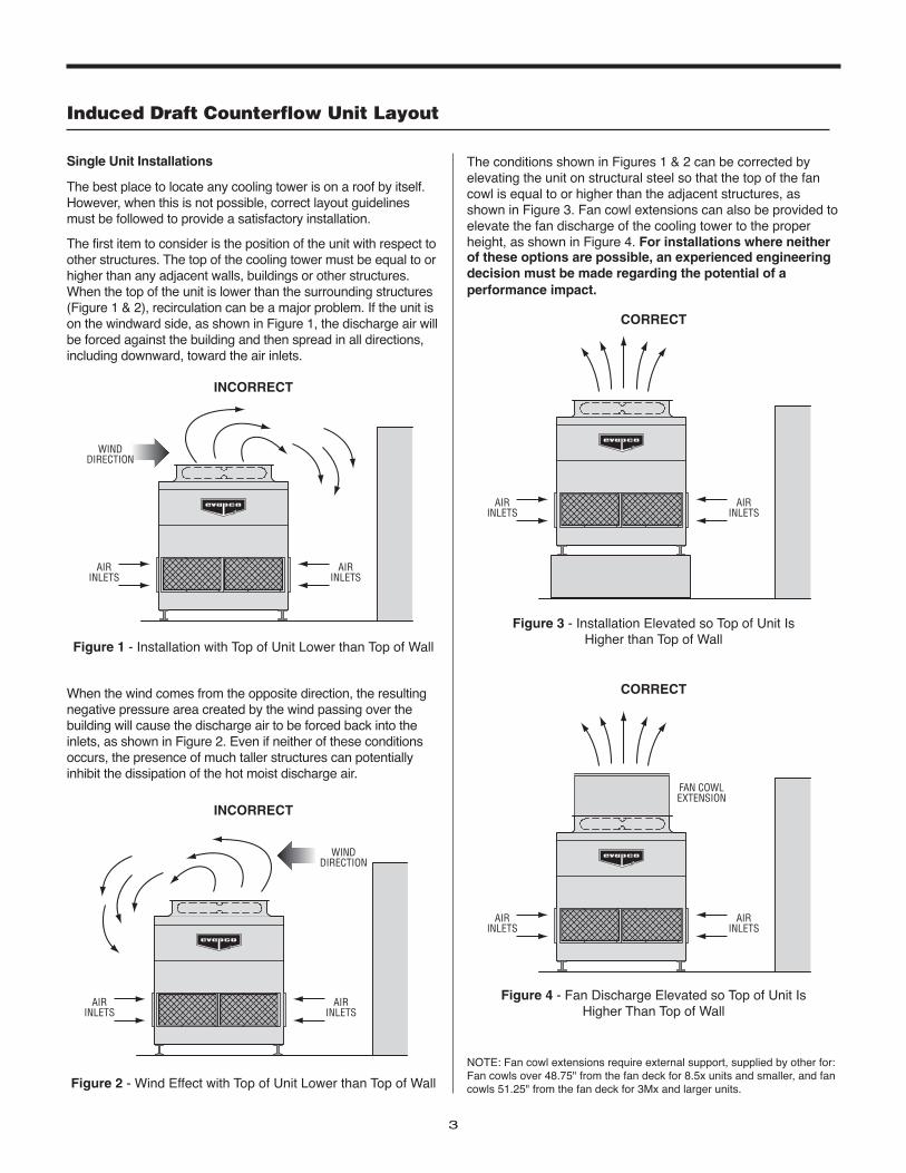
Single Unit Installations
The best place to locate any cooling tower is on a roof by itself.However, when this is not possible, correct layout guidelinesmust be followed to provide a satisfactory installation.
The first item to consider is the position of the unit with respect toother structures. The top of the cooling tower must be equal to orhigher than any adjacent walls, buildings or other structures.When the top of the unit is lower than the surrounding structures(Figure 1 & 2), recirculation can be a major problem. If the unit ison the windward side, as shown in Figure 1, the discharge air willbe forced against the building and then spread in all directions,including downward, toward the air inlets.
When the wind comes from the opposite direction, the resultingnegative pressure area created by the wind passing over thebuilding will cause the discharge air to be forced back into theinlets, as shown in Figure 2. Even if neither of these conditionsoccurs, the presence of much taller structures can potentiallyinhibit the dissipation of the hot moist discharge air.
AIRINLETS
AIRINLETS
WINDDIRECTION
Figure 1 - Installation with Top of Unit Lower than Top of Wall
WINDDIRECTION
AIRINLETS
AIRINLETS
Figure 2 - Wind Effect with Top of Unit Lower than Top of Wall
INCORRECT
INCORRECT
The conditions shown in Figures 1 & 2 can be corrected byelevating the unit on structural steel so that the top of the fancowl is equal to or higher than the adjacent structures, asshown in Figure 3. Fan cowl extensions can also be provided toelevate the fan discharge of the cooling tower to the properheight, as shown in Figure 4. For installations where neitherof these options are possible, an experienced engineeringdecision must be made regarding the potential of aperformance impact.
AIRINLETS
AIRINLETS
Figure 3 - Installation Elevated so Top of Unit Is Higher than Top of Wall
CORRECT
AIRINLETS
FAN COWLEXTENSION
AIRINLETS
Figure 4 - Fan Discharge Elevated so Top of Unit Is Higher Than Top of Wall
CORRECT
Induced Draft Counterflow Unit Layout
NOTE: Fan cowl extensions require external support, supplied by other for:Fan cowls over 48.75" from the fan deck for 8.5x units and smaller, and fancowls 51.25" from the fan deck for 3Mx and larger units.
4
for LIFE Equipment Layout Manual
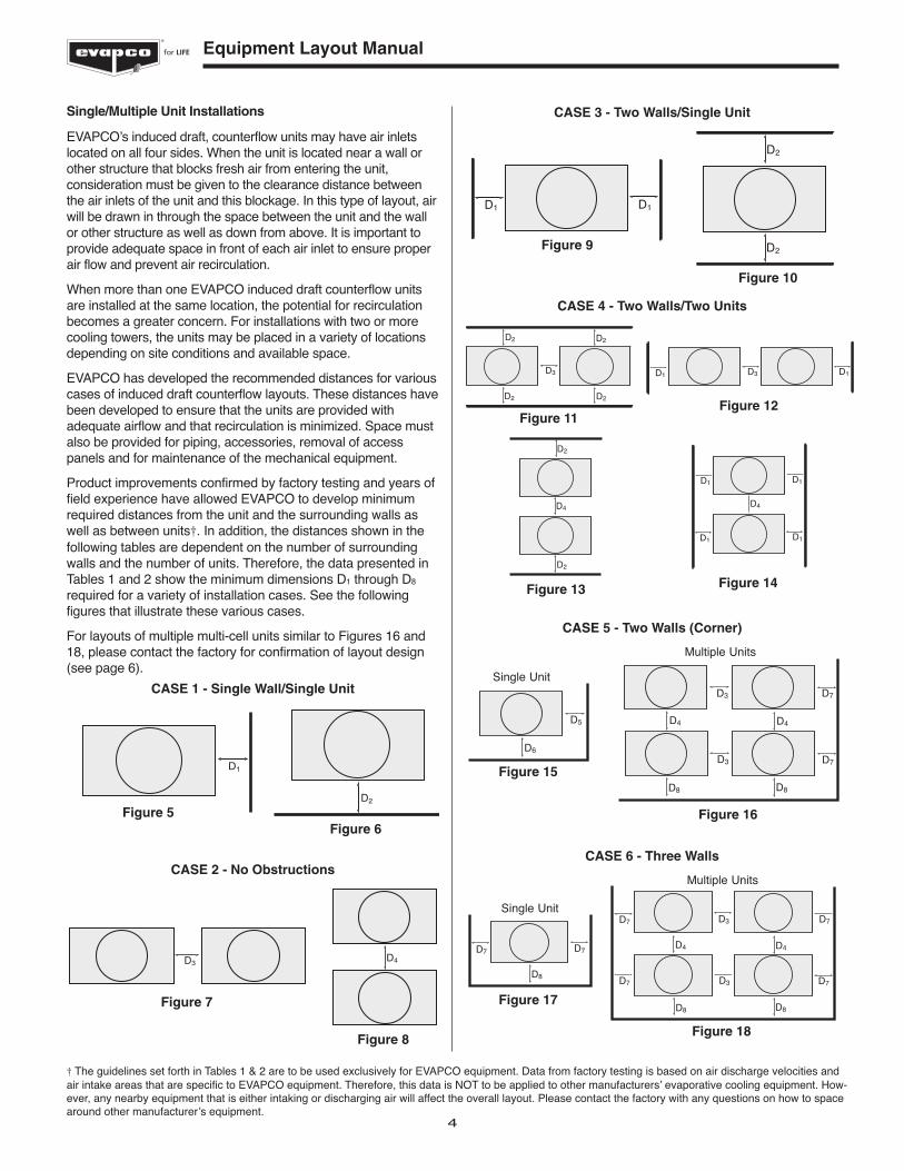
Single/Multiple Unit Installations
EVAPCO’s induced draft, counterflow units may have air inletslocated on all four sides. When the unit is located near a wall orother structure that blocks fresh air from entering the unit,consideration must be given to the clearance distance betweenthe air inlets of the unit and this blockage. In this type of layout, airwill be drawn in through the space between the unit and the wallor other structure as well as down from above. It is important toprovide adequate space in front of each air inlet to ensure properair flow and prevent air recirculation.
When more than one EVAPCO induced draft counterflow unitsare installed at the same location, the potential for recirculationbecomes a greater concern. For installations with two or morecooling towers, the units may be placed in a variety of locationsdepending on site conditions and available space.
EVAPCO has developed the recommended distances for variouscases of induced draft counterflow layouts. These distances havebeen developed to ensure that the units are provided withadequate airflow and that recirculation is minimized. Space mustalso be provided for piping, accessories, removal of accesspanels and for maintenance of the mechanical equipment.
Product improvements confirmed by factory testing and years offield experience have allowed EVAPCO to develop minimumrequired distances from the unit and the surrounding walls aswell as between units†. In addition, the distances shown in thefollowing tables are dependent on the number of surroundingwalls and the number of units. Therefore, the data presented inTables 1 and 2 show the minimum dimensions D1 through D8
required for a variety of installation cases. See the followingfigures that illustrate these various cases.
For layouts of multiple multi-cell units similar to Figures 16 and18, please contact the factory for confirmation of layout design(see page 6).
† The guidelines set forth in Tables 1 & 2 are to be used exclusively for EVAPCO equipment. Data from factory testing is based on air discharge velocities andair intake areas that are specific to EVAPCO equipment. Therefore, this data is NOT to be applied to other manufacturers’ evaporative cooling equipment. How-ever, any nearby equipment that is either intaking or discharging air will affect the overall layout. Please contact the factory with any questions on how to spacearound other manufacturer’s equipment.
CASE 1 - Single Wall/Single Unit
D2
D1
Figure 5Figure 6
D3D4
Figure 7
Figure 8
CASE 2 - No Obstructions
CASE 3 - Two Walls/Single Unit
D1D1
D2
D2
Figure 9
Figure 10
CASE 4 - Two Walls/Two Units
D2
D2
D3
D2
D2
D2
D4
D2
D1 D3 D1
D1 D1
D4
D1D1
Figure 11Figure 12
Figure 13 Figure 14
CASE 5 - Two Walls (Corner)
D6
D5 D4
D3
D3
D8 D8
D4
D7
D7
Single Unit
Multiple Units
Figure 15
Figure 16
CASE 6 - Three Walls
D7 D7
D8
D7
D8
D4
D3
D3
D8
D4
D7
D7D7
Single Unit
Multiple Units
Figure 17
Figure 18
5
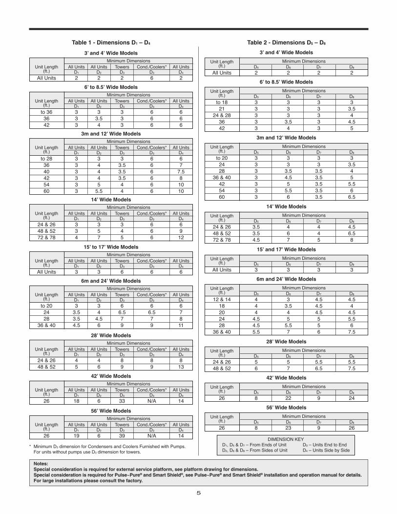
Table 1 - Dimensions D1 – D4 Table 2 - Dimensions D5 – D8
Unit Length(ft.) D5 D6 D7 D8
All Units 2 2 2 2
Minimum Dimensions
3’ and 4’ Wide Models
* Minimum D3 dimension for Condensers and Coolers Furnished with Pumps. For units without pumps use D3 dimension for towers.
DIMENSION KEYD1, D5 & D7 – From Ends of Unit D3 – Units End to EndD2, D6 & D8 – From Sides of Unit D4 – Units Side by Side
Unit Length All Units All Units Towers Cond./Coolers* All Units(ft.) D1 D2 D3 D3 D4
All Units 2 2 2 6 2
Minimum Dimensions
3’ and 4’ Wide Models
Unit Length All Units All Units Towers Cond./Coolers* All Units(ft.) D1 D2 D3 D3 D4
to 36 3 3 3 6 636 3 3.5 3 6 642 3 4 3 6 6
Minimum Dimensions
6’ to 8.5’ Wide Models
Unit Length All Units All Units Towers Cond./Coolers* All Units(ft.) D1 D2 D3 D3 D4
to 28 3 3 3 6 636 3 4 3.5 6 740 3 4 3.5 6 7.542 3 4 3.5 6 854 3 5 4 6 1060 3 5.5 4 6 10
Minimum Dimensions
3m and 12’ Wide Models
Unit Length All Units All Units Towers Cond./Coolers* All Units(ft.) D1 D2 D3 D3 D4
24 & 26 3 3 3 6 648 & 52 3 5 4 6 972 & 78 4 7 5 6 12
Minimum Dimensions
14’ Wide Models
Unit Length All Units All Units Towers Cond./Coolers* All Units(ft.) D1 D2 D3 D3 D4
All Units 3 3 6 6 6
Minimum Dimensions
15’ to 17’ Wide Models
Unit Length All Units All Units Towers Cond./Coolers* All Units(ft.) D1 D2 D3 D3 D4
to 20 3 3 6 6 624 3.5 4 6.5 6.5 728 3.5 4.5 7 7 8
36 & 40 4.5 6 9 9 11
Minimum Dimensions
6m and 24’ Wide Models
Unit Length All Units All Units Towers Cond./Coolers* All Units(ft.) D1 D2 D3 D3 D4
24 & 26 4 4 8 8 848 & 52 5 6 9 9 13
Minimum Dimensions
28’ Wide Models
Unit Length All Units All Units Towers Cond./Coolers* All Units(ft.) D1 D2 D3 D3 D4
26 18 6 33 N/A 14
Minimum Dimensions
42’ Wide Models
Unit Length All Units All Units Towers Cond./Coolers* All Units(ft.) D1 D2 D3 D3 D4
26 19 6 39 N/A 14
Minimum Dimensions
56’ Wide Models
Unit Length(ft.) D5 D6 D7 D8
to 18 3 3 3 321 3 3 3 3.5
24 & 28 3 3 3 436 3 3.5 3 4.542 3 4 3 5
Minimum Dimensions
6’ to 8.5’ Wide Models
Unit Length(ft.) D5 D6 D7 D8
to 20 3 3 3 324 3 3 3 3.528 3 3.5 3.5 4
36 & 40 3 4.5 3.5 542 3 5 3.5 5.554 3 5.5 3.5 660 3 6 3.5 6.5
Minimum Dimensions
3m and 12’ Wide Models
Unit Length(ft.) D5 D6 D7 D8
24 & 26 3.5 4 4 4.548 & 52 3.5 6 4 6.572 & 78 4.5 7 5 8
Minimum Dimensions
14’ Wide Models
Unit Length(ft.) D5 D6 D7 D8
All Units 3 3 3 3
Minimum Dimensions
15’ and 17’ Wide Models
Unit Length(ft.) D5 D6 D7 D8
12 & 14 4 3 4.5 4.518 4 3.5 4.5 420 4 4 4.5 4.524 4.5 5 5 5.528 4.5 5.5 5 6
36 & 40 5.5 7 6 7.5
Minimum Dimensions
6m and 24’ Wide Models
Unit Length(ft.) D5 D6 D7 D8
24 & 26 5 5 5.5 5.548 & 52 6 7 6.5 7.5
Minimum Dimensions
28’ Wide Models
Unit Length(ft.) D5 D6 D7 D8
26 8 22 9 24
Minimum Dimensions
42’ Wide Models
Unit Length(ft.) D5 D6 D7 D8
26 8 23 9 26
Minimum Dimensions
56’ Wide Models
Notes: Special consideration is required for external service platform, see platform drawing for dimensions.Special consideration is required for Pulse~Pure® and Smart Shield®, see Pulse~Pure® and Smart Shield® installation and operation manual for details.For large installations please consult the factory.
6
for LIFE Equipment Layout Manual
Large Installations
For large cooling tower installations that have 4 or more units, itis imperative that the unit layout be carefully examined duringthe design of the system.
Very large multiple unit installations can create their ownenvironment. Under certain weather and atmospheric conditions,the large quantities of discharge air will cause the wet bulbtemperature in the immediate area to be higher than the localdesign data.The minimum dimensions shown in Tables 1 and 2should be increased whenever possible in order to allow for anadditional safety factor. The amount of increase is dependent onthe number of units, type of installation, existing equipment andunit surroundings.
The surrounding area plays an important part in the design of alarge installation. Locating a large installation in a valley orbetween buildings will increase the chances that the dischargeair will recirculate, thereby raising the entering wet bulbtemperature. If it is determined that the surrounding conditionscould cause recirculation, the units must be spaced properly andsized at the anticipated entering wet bulb conditions.
Another important consideration when dealing with larger multipleunit installations is prevailing winds. Although prevailing windconditions generally change with the season, the wind directionduring the hottest part of the year is of utmost importance. Tominimize the potential for recirculation, it is best to locate the unitsso that the prevailing wind is oriented as shown in Figure 19.
Consult your local representative or EVAPCO’s MarketingDepartment at 410-756-2600 for recommended layoutguidelines for very large multiple unit installations.
Special Enclosures
Occasionally, induced draft counterflow units are installed in anenclosure. These installations require special consideration ofthe unit layout to ensure trouble free operation. Typicalinstallations consist of units installed in solid wall or louveredenclosures or units that are located in a well.
Figure 19 - Prevailing Wind
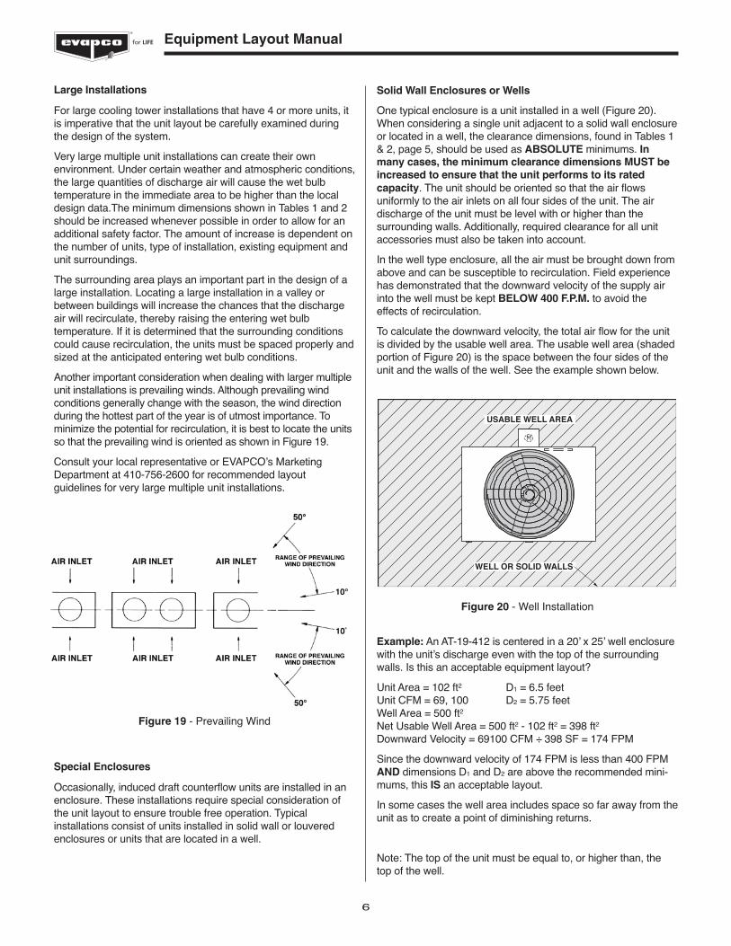
Solid Wall Enclosures or Wells
One typical enclosure is a unit installed in a well (Figure 20).When considering a single unit adjacent to a solid wall enclosureor located in a well, the clearance dimensions, found in Tables 1& 2, page 5, should be used as ABSOLUTE minimums. Inmany cases, the minimum clearance dimensions MUST be
increased to ensure that the unit performs to its rated
capacity. The unit should be oriented so that the air flowsuniformly to the air inlets on all four sides of the unit. The airdischarge of the unit must be level with or higher than thesurrounding walls. Additionally, required clearance for all unitaccessories must also be taken into account.
In the well type enclosure, all the air must be brought down fromabove and can be susceptible to recirculation. Field experiencehas demonstrated that the downward velocity of the supply airinto the well must be kept BELOW 400 F.P.M. to avoid theeffects of recirculation.
To calculate the downward velocity, the total air flow for the unitis divided by the usable well area. The usable well area (shadedportion of Figure 20) is the space between the four sides of theunit and the walls of the well. See the example shown below.
Example: An AT-19-412 is centered in a 20’ x 25’ well enclosurewith the unit’s discharge even with the top of the surroundingwalls. Is this an acceptable equipment layout?
Unit Area = 102 ft2 D1 = 6.5 feetUnit CFM = 69, 100 D2 = 5.75 feetWell Area = 500 ft2
Net Usable Well Area = 500 ft2 - 102 ft2 = 398 ft2
Downward Velocity = 69100 CFM ÷ 398 SF = 174 FPM
Since the downward velocity of 174 FPM is less than 400 FPMAND dimensions D1 and D2 are above the recommended mini-mums, this IS an acceptable layout.
In some cases the well area includes space so far away from theunit as to create a point of diminishing returns.
Note: The top of the unit must be equal to, or higher than, thetop of the well.
Figure 20 - Well Installation
USABLE WELL AREA
WELL OR SOLID WALLS
M
7
Louvered Wall Enclosures
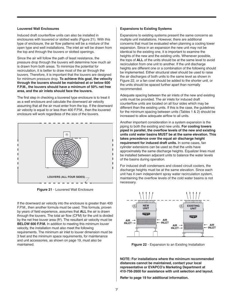
Induced draft counterflow units can also be installed inenclosures with louvered or slotted walls (Figure 21). With thistype of enclosure, the air flow patterns will be a mixture of theopen type and well installations. The inlet air will be drawn fromthe top and through the louvers or slotted openings.
Since the air will follow the path of least resistance, thepressure drop through the louvers will determine how much airis drawn from both areas. To minimize the potential forrecirculation, it is better to draw most of the air through thelouvers. Therefore, it is important that the louvers are designedfor minimum pressure drop. To achieve this goal, the velocitythrough the louvers should be maintained at or below 600F.P.M., the louvers should have a minimum of 50% net freearea, and the air inlets should face the louvers.
The first step in checking a louvered type enclosure is to treat itas a well enclosure and calculate the downward air velocityassuming that all the air must enter from the top. If the downwardair velocity is equal to or less than 400 F.P.M., then the louveredenclosure will work regardless of the size of the louvers.
If the downward air velocity into the enclosure is greater than 400F.P.M., then another formula must be used. This formula, provenby years of field experience, assumes that ALL the air is drawnthrough the louvers. The total air flow (CFM) for the unit is dividedby the net free louver area (ft2). The resultant air velocity must beBELOW 600 F.P.M. In addition to meeting this minimum louvervelocity, the installation must also meet the followingrequirements. The minimum air inlet to louver dimension must be3 feet and the minimum space requirements, for maintenanceand unit accessories, as shown on page 19, must also bemaintained.
LOUVERS (ALL FOUR SIDES)
M
Figure 21 - Louvered Wall Enclosure
Expansions to Existing Systems
Expansions to existing systems present the same concerns asmultiple unit installations. However, there are additionalconcerns that must be evaluated when planning a cooling towerexpansion. Since in an expansion the new unit may not beidentical to the existing one, it is important to examine theheights of the new and the existing units. Whenever possible,the tops of ALL of the units should be at the same level to avoidrecirculation from one unit to another. If the unit dischargeheights are different one or a combination of the following shouldbe implemented. Either structural steel should be used to raisethe air discharges of both units to the same level as shown inFigure 22, or a fan cowl should be added to the shorter unit, orthe units should be spaced further apart than normallyrecommended.
Adequate spacing between the air inlets of the new and existingunits must be provided. The air inlets for induced draftcounterflow units are located on all four sides which may bedifferent than the existing units. If this is the case, the guidelinesfor the minimum spacing between units (Tables 1 & 2) should beincreased to allow adequate airflow to all units.
Another important consideration in a system expansion is thepiping to both the existing and new units. For cooling towerspiped in parallel, the overflow levels of the new and existingunits cold water basins MUST be at the same elevation. Thistakes precedence over the equal air discharge heightrequirement for induced draft units. In some cases, fancylinder extensions can be used so that the units haveapproximately the same discharge heights. Equalizer lines mustbe installed between adjacent units to balance the water levelsof the basins during operation.
For induced draft condensers and closed circuit coolers, thedischarge heights must be at the same elevation. Since eachunit has it own independent spray water recirculation system,maintaining the overflow levels of the cold water basins is notnecessary.
NOTE: For installations where the minimum recommendeddistances cannot be maintained, contact your localrepresentative or EVAPCO’s Marketing Department at 410-756-2600 for assistance with unit selection and layout.
Refer to page 19 for additional information.
EXISTINGUNIT
NEWUNIT
AIRINLET
AIRINLET
M
AIRINLET
AIRINLET
M
Figure 22 - Expansion to an Existing Installation
8
for LIFE Equipment Layout Manual
Single Unit Installations
The best place to locate any cooling tower is on a roof by itself.However, when this is not possible, correct layout guidelinesmust be followed to provide a satisfactory installation.
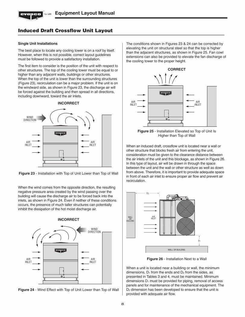
The first item to consider is the position of the unit with respect toother structures. The top of the cooling tower must be equal to orhigher than any adjacent walls, buildings or other structures.When the top of the unit is lower than the surrounding structures(Figure 23), recirculation can be a major problem. If the unit is onthe windward side, as shown in Figure 23, the discharge air willbe forced against the building and then spread in all directions,including downward, toward the air inlets.
When the wind comes from the opposite direction, the resultingnegative pressure area created by the wind passing over thebuilding will cause the discharge air to be forced back into theinlets, as shown in Figure 24. Even if neither of these conditionsoccurs, the presence of much taller structures can potentiallyinhibit the dissipation of the hot moist discharge air.
Induced Draft Crossflow Unit Layout
AIRINLET
AIRINLET
WINDDIRECTION
Figure 23 - Installation with Top of Unit Lower than Top of Wall
INCORRECT
AIRINLET
AIRINLET
WINDDIRECTION
Figure 24 - Wind Effect with Top of Unit Lower than Top of Wall
INCORRECT
The conditions shown in Figures 23 & 24 can be corrected byelevating the unit on structural steel so that the top is higherthan the adjacent structures, as shown in Figure 25. Fan cowlextensions can also be provided to elevate the fan discharge ofthe cooling tower to the proper height.
When an induced draft, crossflow unit is located near a wall orother structure that blocks fresh air from entering the unit,consideration must be given to the clearance distance betweenthe air inlets of the unit and this blockage, as shown in Figure 26.In this type of layout, air will be drawn in through the spacebetween the unit and the wall or other structure as well as downfrom above. Therefore, it is important to provide adequate spacein front of each air inlet to ensure proper air flow and prevent airrecirculation.
AIRINLET
AIRINLET
Figure 25 - Installation Elevated so Top of Unit Is Higher than Top of Wall
CORRECT
AIRINLET
WALLOR
BUILDING
WALL OR BUILDING
D2
D1
Figure 26 - Installation Next to a Wall
When a unit is located near a building or wall, the minimumdimensions, D1 from the ends and D2 from the sides, aspresented in Tables 3 and 4, must be maintained. Minimumdimensions D1 must be provided for piping, removal of accesspanels and for maintenance of the mechanical equipment. TheD2 dimension has been developed to ensure that the unit isprovided with adequate air flow.
9
CELL SIZEUNIT WxLxH
STYLE (ft.) One Cell Two Cell Three Cell Four Cell
AXS All Sizes 3.5 3.5 3.5 3.5
PHC All Sizes 4 4 4 4
Minimum DimensionsD1
Table 3 – Minimum D1 Dimensions
NOTE: Consult the factory on the D2 dimension forapplications with 5 or more cells.
D3
AIRINLET
AIRINLET
AIRINLET
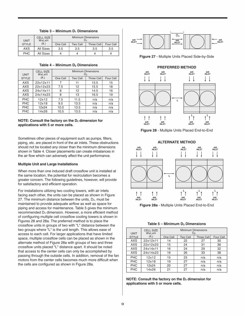
Figure 27 - Multiple Units Placed Side-by-Side
L
L L
AIRINLET
AIRINLET
AIRINLET
AIRINLET
AIRINLET
AIRINLET
AIRINLET
AIRINLET
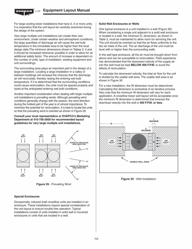
Figure 28 - Multiple Units Placed End-to-End
PREFERRED METHOD
L
L L
AIRINLET
AIRINLET
AIRINLET
AIRINLET
AIRINLET
AIRINLET
AIRINLET
AIRINLET
L
AIRINLET
AIRINLET
Figure 28a - Multiple Units Placed End-to-End
ALTERNATE METHOD
NOTE: Consult the factory on the D3 dimension forapplications with 5 or more cells.
Sometimes other pieces of equipment such as pumps, filters,piping, etc. are placed in front of the air inlets. These obstructionsshould not be located any closer than the minimum dimensionsshown in Table 4. Closer placements can create imbalances inthe air flow which can adversely affect the unit performance.
Multiple Unit and Large Installations
When more than one induced draft crossflow unit is installed atthe same location, the potential for recirculation becomes agreater concern. The following guidelines, however, will providefor satisfactory and efficient operation.
For installations utilizing two cooling towers, with air inletsfacing each other, the units can be placed as shown in Figure27. The minimum distance between the units, D3, must bemaintained to provide adequate airflow as well as space forpiping and access for maintenance. Table 5 gives the minimumrecommended D3 dimension. However, a more efficient methodof configuring multiple cell crossflow cooling towers is shown inFigures 28 and 28a. The preferred method is to place thecrossflow units in groups of two with "L" distance between thetwo groups where "L" is the unit length. This allows ease ofaccess to each cell. For larger applications that have limitedspace, multiple crossflow cells can be placed as shown in thealternate method of Figure 28a with groups of two and threecrossflow units placed "L" distance apart. It should be notedthat access to the center cells can only be accomplished bypassing through the outside cells. In addition, removal of the fanmotors from the center cells becomes much more difficult whenthe cells are configured as shown in Figure 28a.
CELL SIZEUNIT WxLxH
STYLE (ft.) One Cell Two Cell Three Cell Four Cell
AXS 22x12x11 7 11 13.5 15AXS 22x12x23 7.5 12 15.5 18AXS 24x14x11 8 12 14.5 16AXS 24x14x23 8 13 16.5 19
PHC 12x12 7.5 11.5 n/a n/aPHC 12x18 9.5 13.5 n/a n/aPHC 12x24 10.0 13.5 n/a n/aPHC 14x26 10.5 13.5 n/a n/a
Minimum DimensionsD2
Table 4 – Minimum D2 Dimensions
CELL SIZEUNIT WxLxH
STYLE (ft.) One Cell Two Cell Three Cell Four CellAXS 22x12x11 14 22 27 30AXS 22x12x23 15 24 31 36AXS 24x14x11 16 24 29 32AXS 24x14x23 16 26 33 38
PHC 12x12 15 23 n/a n/aPHC 12x18 19 27 n/a n/aPHC 12x24 20 27 n/a n/aPHC 14x26 21 27 n/a n/a
Minimum DimensionsD3
Table 5 – Minimum D3 Dimensions
10
for LIFE Equipment Layout Manual
For large cooling tower installations that have 3, 4 or more units,it is imperative that the unit layout be carefully examined duringthe design of the system.
Very large multiple unit installations can create their ownenvironment. Under certain weather and atmospheric conditions,the large quantities of discharge air will cause the wet bulbtemperature in the immediate area to be higher than the localdesign data.The minimum dimensions shown in Tables 3, 4 and5 should be increased whenever possible in order to allow for anadditional safety factor. The amount of increase is dependent onthe number of units, type of installation, existing equipment andunit surroundings.
The surrounding area plays an important part in the design of alarge installation. Locating a large installation in a valley orbetween buildings will increase the chances that the dischargeair will recirculate, thereby raising the entering wet bulbtemperature. If it is determined that the surrounding conditionscould cause recirculation, the units must be spaced properly andsized at the anticipated entering wet bulb conditions.
Another important consideration when dealing with larger multipleunit installations is prevailing winds. Although prevailing windconditions generally change with the season, the wind directionduring the hottest part of the year is of utmost importance. Tominimize the potential for recirculation, it is best to locate the unitsso that the prevailing wind is oriented as shown in Figure 29.
Consult your local representative or EVAPCO’s MarketingDepartment at 410-756-2600 for recommended layoutguidelines for very large multiple unit installations.
Special Enclosures
Occasionally, induced draft crossflow units are installed in anenclosure. These installations require special consideration ofthe unit layout to ensure trouble free operation. Typicalinstallations consist of units installed in solid wall or louveredenclosures or units that are located in a well.
AIRINLET
AIRINLET
AIRINLET
AIRINLET
AIRINLET
AIRINLET
50°
50°
10°
10°
RANGE OF PREVAILINGWIND DIRECTION
RANGE OF PREVAILINGWIND DIRECTION
Figure 29 - Prevailing Wind
Solid Wall Enclosures or Wells
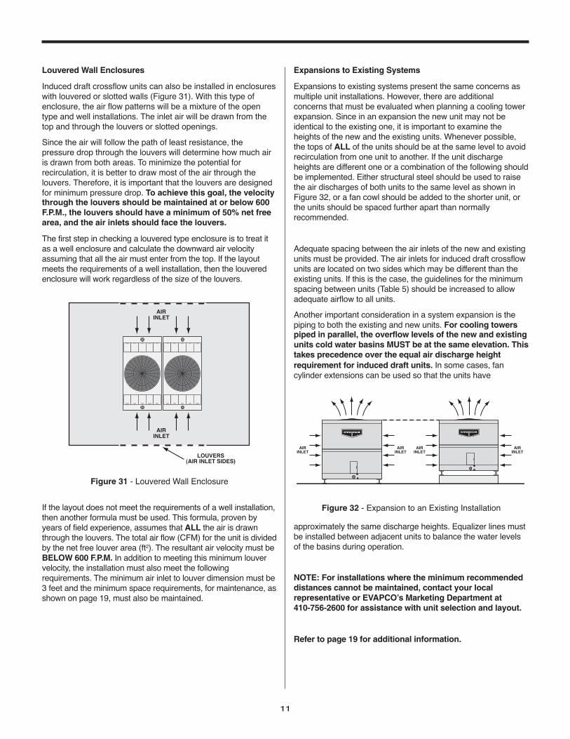
One typical enclosure is a unit installed in a well (Figure 30).When considering a single unit adjacent to a solid wall enclosureor located in a well, the minimum D1 dimension, as shown inTable 3, must be maintained to allow room for servicing the unit.The unit should be oriented so that the air flows uniformly to thetwo air inlets of the unit. The air discharge of the unit must belevel with or higher than the surrounding walls.
In the well type enclosure, all the air must be brought down fromabove and can be susceptible to recirculation. Field experiencehas demonstrated that the downward velocity of the supply airinto the well must be kept BELOW 400 F.P.M. to avoid theeffects of recirculation.
To calculate the downward velocity, the total air flow for the unitis divided by the usable well area. The usable well area is asshown in Figure 30.
For a new installation, the W dimension must be determined.Calculating this dimension is somewhat of an iterative process.Also note that the minimum W dimension will vary for eachapplication. A crossflow tower well layout will be acceptable oncethe minimum W dimension is determined that ensures thedownload velocity into the well is 400 F.P.M. or less.
W
AIRINLET
AIRINLET
1’MAXIMUM
4’MAXIMUM
USABLE WELL AREA
Figure 30 - Well Installation
11
Louvered Wall Enclosures
Induced draft crossflow units can also be installed in enclosureswith louvered or slotted walls (Figure 31). With this type ofenclosure, the air flow patterns will be a mixture of the opentype and well installations. The inlet air will be drawn from thetop and through the louvers or slotted openings.
Since the air will follow the path of least resistance, thepressure drop through the louvers will determine how much airis drawn from both areas. To minimize the potential forrecirculation, it is better to draw most of the air through thelouvers. Therefore, it is important that the louvers are designedfor minimum pressure drop. To achieve this goal, the velocitythrough the louvers should be maintained at or below 600F.P.M., the louvers should have a minimum of 50% net freearea, and the air inlets should face the louvers.
The first step in checking a louvered type enclosure is to treat itas a well enclosure and calculate the downward air velocityassuming that all the air must enter from the top. If the layoutmeets the requirements of a well installation, then the louveredenclosure will work regardless of the size of the louvers.
If the layout does not meet the requirements of a well installation,then another formula must be used. This formula, proven byyears of field experience, assumes that ALL the air is drawnthrough the louvers. The total air flow (CFM) for the unit is dividedby the net free louver area (ft2). The resultant air velocity must beBELOW 600 F.P.M. In addition to meeting this minimum louvervelocity, the installation must also meet the followingrequirements. The minimum air inlet to louver dimension must be3 feet and the minimum space requirements, for maintenance, asshown on page 19, must also be maintained.
AIRINLET
AIRINLET
LOUVERS(AIR INLET SIDES)
Figure 31 - Louvered Wall Enclosure
Expansions to Existing Systems
Expansions to existing systems present the same concerns asmultiple unit installations. However, there are additionalconcerns that must be evaluated when planning a cooling towerexpansion. Since in an expansion the new unit may not beidentical to the existing one, it is important to examine theheights of the new and the existing units. Whenever possible,the tops of ALL of the units should be at the same level to avoidrecirculation from one unit to another. If the unit dischargeheights are different one or a combination of the following shouldbe implemented. Either structural steel should be used to raisethe air discharges of both units to the same level as shown inFigure 32, or a fan cowl should be added to the shorter unit, orthe units should be spaced further apart than normallyrecommended.
Adequate spacing between the air inlets of the new and existingunits must be provided. The air inlets for induced draft crossflowunits are located on two sides which may be different than theexisting units. If this is the case, the guidelines for the minimumspacing between units (Table 5) should be increased to allowadequate airflow to all units.
Another important consideration in a system expansion is thepiping to both the existing and new units. For cooling towerspiped in parallel, the overflow levels of the new and existingunits cold water basins MUST be at the same elevation. Thistakes precedence over the equal air discharge heightrequirement for induced draft units. In some cases, fancylinder extensions can be used so that the units have
approximately the same discharge heights. Equalizer lines mustbe installed between adjacent units to balance the water levelsof the basins during operation.
NOTE: For installations where the minimum recommendeddistances cannot be maintained, contact your localrepresentative or EVAPCO’s Marketing Department at 410-756-2600 for assistance with unit selection and layout.
Refer to page 19 for additional information.
AIRINLET
AIRINLET
AIRINLET
AIRINLET
Figure 32 - Expansion to an Existing Installation
12
for LIFE Equipment Layout Manual
Single Unit Installations
The best place for a cooling tower is on a roof by itself. However,when this is not possible, correct layout guidelines must befollowed to provide a satisfactory installation. There are varioustypes of forced draft units that are discussed in this section,which include both centrifugal and axial fan types. The centrifugalfan models include units with single side air inlets. Also includedin this section are layout guidelines for EVAPCO’s centrifugal fanLR/LP end air inlet units. Special consideration is required forexternal service platforms available on PM style units, seeplatform drawing for dimensions.
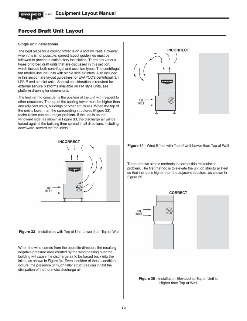
The first item to consider is the position of the unit with respect toother structures. The top of the cooling tower must be higher thanany adjacent walls, buildings or other structures. When the top ofthe unit is lower than the surrounding structures (Figure 33),recirculation can be a major problem. If the unit is on thewindward side, as shown in Figure 33, the discharge air will beforced against the building then spread in all directions, includingdownward, toward the fan inlets.
When the wind comes from the opposite direction, the resultingnegative pressure area created by the wind passing over thebuilding will cause the discharge air to be forced back into theinlets, as shown in Figure 34. Even if neither of these conditionsoccurs, the presence of much taller structures can inhibit thedissipation of the hot moist discharge air.
AIRINLET
Figure 33 - Installation with Top of Unit Lower than Top of Wall
INCORRECT
There are two simple methods to correct this recirculationproblem. The first method is to elevate the unit on structural steelso that the top is higher than the adjacent structure, as shown inFigure 35.
AIRINLET
Figure 34 - Wind Effect with Top of Unit Lower than Top of Wall
INCORRECT
Forced Draft Unit Layout
AIRINLET
Figure 35 - Installation Elevated so Top of Unit is Higher than Top of Wall
CORRECT
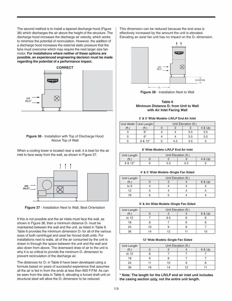
The second method is to install a tapered discharge hood (Figure36) which discharges the air above the height of the structure. Thedischarge hood increases the discharge air velocity, which worksto minimize the potential of recirculation. However, the addition ofa discharge hood increases the external static pressure that thefans must overcome which may require the next larger size fanmotor. For installations where neither of these options arepossible, an experienced engineering decision must be maderegarding the potential of a performance impact.
When a cooling tower is located near a wall, it is best for the airinlet to face away from the wall, as shown in Figure 37.
If this is not possible and the air inlets must face the wall, asshown in Figure 38, then a minimum distance D1 must bemaintained between the wall and the unit, as listed in Table 6.Table 6 provides the minimum dimension D1 for all of the varioussizes of both centrifugal and axial fan forced draft units. Forinstallations next to walls, all of the air consumed by the unit isdrawn in through the space between the unit and the wall andalso down from above. The downward draw of air to the unit iswhy it is so critical to provide the minimum D1 dimension toprevent recirculation of the discharge air.
The distances for D1 in Table 6 have been developed using aformula based on years of successful experience that assumesall the air is fed in from the ends at less then 600 F.P.M. As canbe seen from the data in Table 6, elevating a forced draft unit onstructural steel will allow the D1 dimension to be reduced.
13
AIRINLET
Figure 37 - Installation Next to Wall, Best Orientation
AIRINLET
Figure 36 - Installation with Top of Discharge Hood Above Top of Wall
CORRECT AIRINLET
ELEVATION
D1
Figure 38 - Installation Next to Wall
Unit Width Unit Length(ft.) (ft.) 0 2 3 4 & Up3 6* 4 4 3.5 3.5
5 6* 4 4 3.5 3.5
5 9 & 12* 5 4.5 4.5 4
Unit Elevation (ft.)
3’ & 5’ Wide Models–LR/LP End Air Inlet
Table 6Minimum Distance D1 from Unit to Wall
with Air Inlet Facing Wall
Unit Length(ft.) 0 2 3 4 & Up
9 & 12* 6 5.5 5.5 5
Unit Elevation (ft.)
8’ Wide Models–LR/LP End Air Inlet
Unit Length(ft.) 0 2 4 6 & Upto 9 4 4 4 4
12 5 4 4 4
18 6 5 4 4
Unit Elevation (ft.)
4’ & 5’ Wide Models–Single Fan Sided
Unit Length(ft.) 0 2 4 6 & Up
to 12 7 6.5 6 6
18 8 7 6 6
24 10 9 8 7
36 14 12 11 10
Unit Elevation (ft.)
8’ & 3m Wide Models–Single Fan Sided
Unit Length(ft.) 0 2 4 6 & Up
to 12 8 7 7 7
18 9 8 7 7
24 11 10 9 8
36 16 14 12 11
Unit Elevation (ft.)
12’ Wide Models–Single Fan Sided
* Note: The length for the LR/LP end air inlet unit includesthe casing section only, not the entire unit length.
This dimension can be reduced because the end area iseffectively increased by the amount the unit is elevated.Elevating an axial fan unit has no impact on the D1 dimension.
14
for LIFE Equipment Layout Manual
If the required D1 distance shown in Table 6 is too large for theavailable space, the use of a tapered discharge hood (Figure 39)can reduce the distance. The tapered discharge hood should beat least 3 feet tall with an exit air velocity between 1200 and 1500F.P.M. The use of a tapered discharge hood will allow thedistances given in Table 6 to be reduced by 20 percent. However,the minimum D1 distance should never be less than:
3’ and 5’ Wide Models - LR/LP – End Air Inlet = 3’4’ and 5’ Wide Models – Single Fan Sided = 4’8’ Wide Models - LR/LP – End Air Inlet = 3’8’ and 3m Wide Models – Single Fan Sided = 6’12’ Wide Models – Single Fan Sided = 7’
In some installations, other pieces of equipment such asreceivers, compressors, piping, etc. are placed in front of the faninlet. These should not be any closer than the above minimumdimensions. Closer placement can create imbalances in the airflow which has an adverse affect on fan performance.
Multiple Unit & Large Installations
When more than one cooling tower is installed at the samelocation, the potential for recirculation becomes a bigger concernbecause of the larger quantities of air being handled. Thefollowing guidelines, however, will provide for satisfactory andefficient operation.
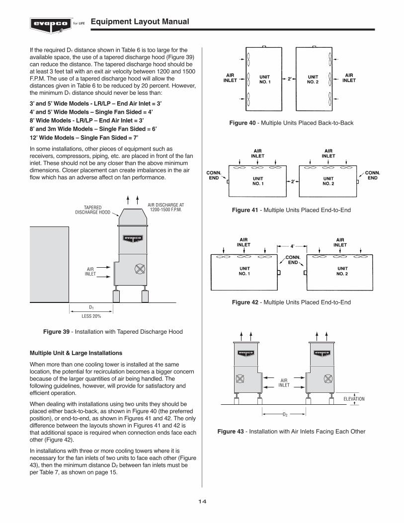
When dealing with installations using two units they should beplaced either back-to-back, as shown in Figure 40 (the preferredposition), or end-to-end, as shown in Figures 41 and 42. The onlydifference between the layouts shown in Figures 41 and 42 isthat additional space is required when connection ends face eachother (Figure 42).
In installations with three or more cooling towers where it isnecessary for the fan inlets of two units to face each other (Figure43), then the minimum distance D2 between fan inlets must beper Table 7, as shown on page 15.
AIRINLET
TAPEREDDISCHARGE HOOD
AIR DISCHARGE AT1200-1500 F.P.M.
LESS 20%
D1
Figure 39 - Installation with Tapered Discharge Hood
Figure 40 - Multiple Units Placed Back-to-Back
Figure 41 - Multiple Units Placed End-to-End
Figure 42 - Multiple Units Placed End-to-End
AIRINLET
ELEVATION
D2
Figure 43 - Installation with Air Inlets Facing Each Other
15
These tables are based on formulas which assume all the airflows to the units from the ends at velocities of less than 600F.P.M. This criteria has been proven through years of successfulexperience with evaporative cooling installations.
If there is not enough room to meet the minimum distances givenin Table 7, the use of tapered discharge hoods may provide agood solution. These hoods should be designed as previouslydescribed, i.e. a minimum of 3 feet tall with an exit air velocitybetween 1200 and 1500 F.P.M. The distances in Table 7 can bereduced 20%. However, the spacing between the fan inlets evenwith discharge hoods, cannot be less than the minimums shownat the top of the next column.
3’ & 5’ Wide Models - LR/LP – End Inlet = 6’ - Side Inlet = 4’ 4’ and 5’ Wide Models – Single Fan Sided = 6’8’ Wide Models - LR/LP – End Inlet = 10’ - Side Inlet = 4’8’ and 3m Wide Models – Single Fan Sided = 10’12’ Wide Models – Single Fan Sided = 11’
Very large multiple unit installations can create their own environ-ment. Under certain weather and atmospheric conditions the largequantities of discharge air will cause the wet bulb temperature inthe immediate area to be higher than local design data. The mini-mum dimensions shown in Tables 6 and 7 should be increasedwhenever possible in order to allow for an additional safety factor.The amount of increase is dependent on the number of units, typeof installation, existing equipment, and unit surroundings.
The surrounding area plays an important part in the design of alarge installation. Locating a large installation in a valley, orbetween buildings will increase the chances that the dischargeair will recirculate, thereby raising the entering wet bulbtemperature.
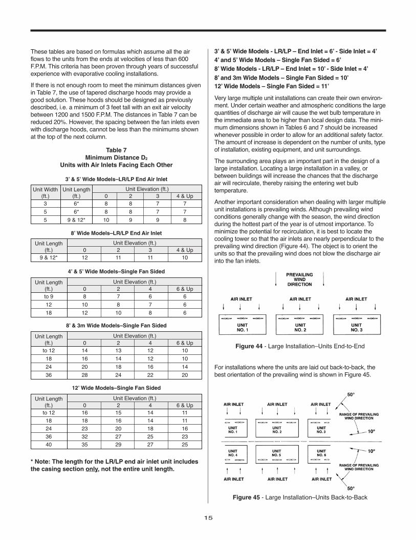
Another important consideration when dealing with larger multipleunit installations is prevailing winds. Although prevailing windconditions generally change with the season, the wind directionduring the hottest part of the year is of utmost importance. Tominimize the potential for recirculation, it is best to locate thecooling tower so that the air inlets are nearly perpendicular to theprevailing wind direction (Figure 44). The object is to orient theunits so that the prevailing wind does not blow the discharge airinto the fan inlets.
Table 7Minimum Distance D2
Units with Air Inlets Facing Each Other
Unit Width Unit Length(ft.) (ft.) 0 2 3 4 & Up3 6* 8 8 7 7
5 6* 8 8 7 7
5 9 & 12* 10 9 9 8
Unit Elevation (ft.)
3’ & 5’ Wide Models–LR/LP End Air Inlet
Unit Length(ft.) 0 2 3 4 & Up
9 & 12* 12 11 11 10
Unit Elevation (ft.)
8’ Wide Models–LR/LP End Air Inlet
Unit Length(ft.) 0 2 4 6 & Upto 9 8 7 6 6
12 10 8 7 6
18 12 10 8 6
Unit Elevation (ft.)
4’ & 5’ Wide Models–Single Fan Sided
Unit Length(ft.) 0 2 4 6 & Up
to 12 14 13 12 10
18 16 14 12 10
24 20 18 16 14
36 28 24 22 20
Unit Elevation (ft.)
8’ & 3m Wide Models–Single Fan Sided
Unit Length(ft.) 0 2 4 6 & Up
to 12 16 15 14 11
18 18 16 14 11
24 23 20 18 16
36 32 27 25 23
40 35 29 27 25
Unit Elevation (ft.)
12’ Wide Models–Single Fan Sided
* Note: The length for the LR/LP end air inlet unit includesthe casing section only, not the entire unit length.
Figure 44 - Large Installation–Units End-to-End
Figure 45 - Large Installation–Units Back-to-Back
For installations where the units are laid out back-to-back, thebest orientation of the prevailing wind is shown in Figure 45.
16
for LIFE Equipment Layout Manual
Special Enclosures
Many times cooling towers are installed in an enclosure. Theseinstallations require special consideration of the unit layout toensure trouble free operation.
Solid Wall Enclosures or Wells
One typical enclosure situation is a unit installed in a well (Figure46). When considering a single unit adjacent to a solid wallenclosure or well, the D1 dimension found in Table 6, page 13must be used as an ABSOLUTE minimum. The cooling towershould be oriented so that the air flows uniformly to the air inletsand the area on the fan side is maximized. The air discharge ofthe unit must be level with or higher than the surrounding walls.
In the well type enclosure, all the air must be brought downfrom above and can be susceptible to recirculation. Fieldexperience has demonstrated that the downward velocity ofthe supply air must be kept BELOW 300 F.P.M. to avoid theeffects of recirculation.
The downward air velocity within some enclosures may ex-ceed the maximum 300 F.P.M. In these situations, a tapereddischarge hood can be used allowing the maximum down-ward air velocity to be increased from 300 F.P.M. to 450 F.P.M.
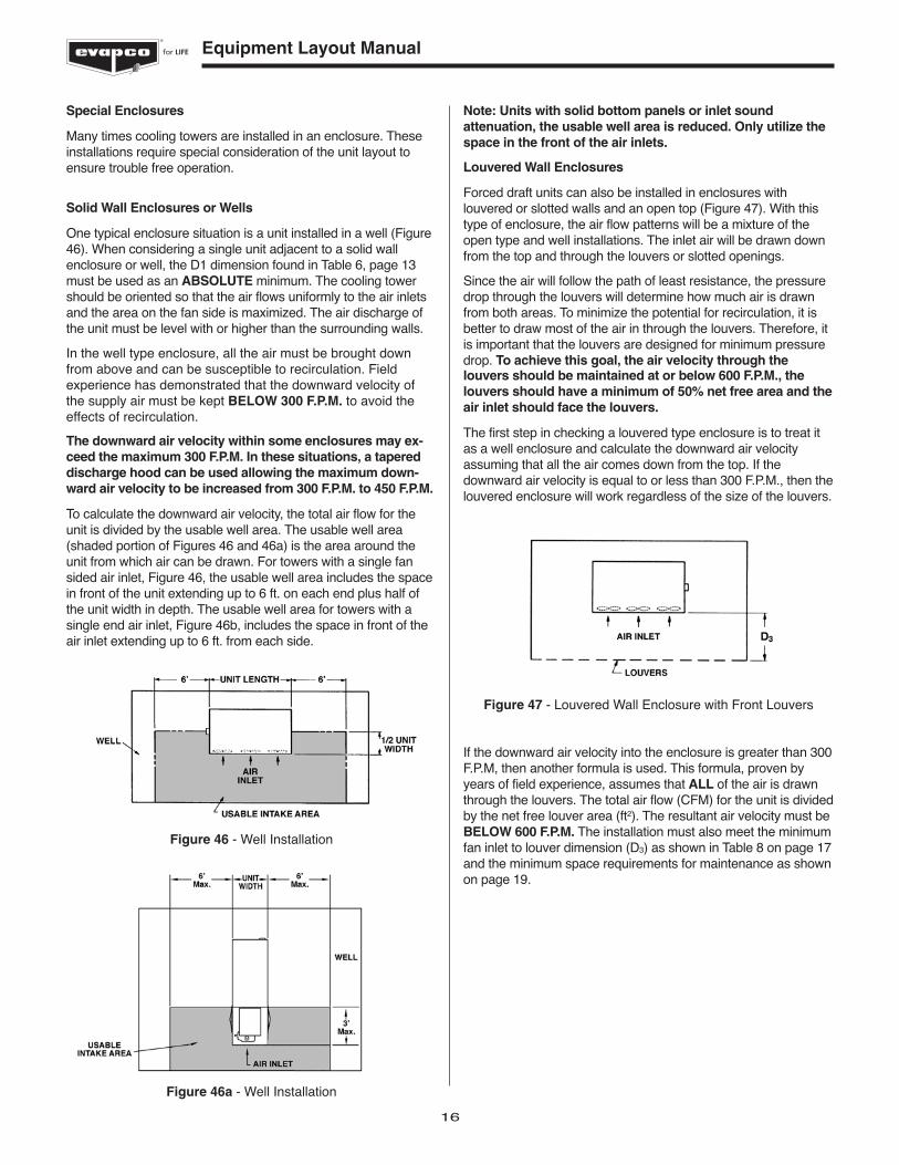
To calculate the downward air velocity, the total air flow for theunit is divided by the usable well area. The usable well area(shaded portion of Figures 46 and 46a) is the area around theunit from which air can be drawn. For towers with a single fansided air inlet, Figure 46, the usable well area includes the spacein front of the unit extending up to 6 ft. on each end plus half ofthe unit width in depth. The usable well area for towers with asingle end air inlet, Figure 46b, includes the space in front of theair inlet extending up to 6 ft. from each side.
Figure 46 - Well Installation
Figure 46a - Well Installation
Note: Units with solid bottom panels or inlet soundattenuation, the usable well area is reduced. Only utilize thespace in the front of the air inlets.
Louvered Wall Enclosures
Forced draft units can also be installed in enclosures withlouvered or slotted walls and an open top (Figure 47). With thistype of enclosure, the air flow patterns will be a mixture of theopen type and well installations. The inlet air will be drawn downfrom the top and through the louvers or slotted openings.
Since the air will follow the path of least resistance, the pressuredrop through the louvers will determine how much air is drawnfrom both areas. To minimize the potential for recirculation, it isbetter to draw most of the air in through the louvers. Therefore, itis important that the louvers are designed for minimum pressuredrop. To achieve this goal, the air velocity through thelouvers should be maintained at or below 600 F.P.M., thelouvers should have a minimum of 50% net free area and theair inlet should face the louvers.
The first step in checking a louvered type enclosure is to treat itas a well enclosure and calculate the downward air velocityassuming that all the air comes down from the top. If thedownward air velocity is equal to or less than 300 F.P.M., then thelouvered enclosure will work regardless of the size of the louvers.
If the downward air velocity into the enclosure is greater than 300F.P.M, then another formula is used. This formula, proven byyears of field experience, assumes that ALL of the air is drawnthrough the louvers. The total air flow (CFM) for the unit is dividedby the net free louver area (ft2). The resultant air velocity must beBELOW 600 F.P.M. The installation must also meet the minimumfan inlet to louver dimension (D3) as shown in Table 8 on page 17and the minimum space requirements for maintenance as shownon page 19.
Figure 47 - Louvered Wall Enclosure with Front Louvers
17
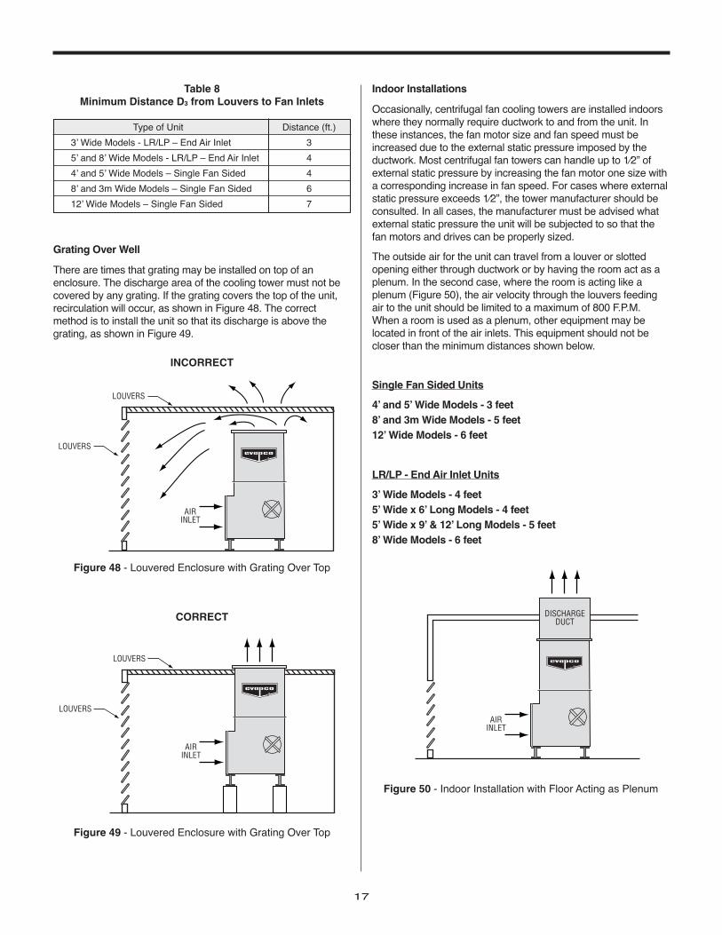
Grating Over Well
There are times that grating may be installed on top of anenclosure. The discharge area of the cooling tower must not becovered by any grating. If the grating covers the top of the unit,recirculation will occur, as shown in Figure 48. The correctmethod is to install the unit so that its discharge is above thegrating, as shown in Figure 49.
Type of Unit Distance (ft.)
3’ Wide Models - LR/LP – End Air Inlet 3
5’ and 8’ Wide Models - LR/LP – End Air Inlet 4
4’ and 5’ Wide Models – Single Fan Sided 4
8’ and 3m Wide Models – Single Fan Sided 6
12’ Wide Models – Single Fan Sided 7
Table 8Minimum Distance D3 from Louvers to Fan Inlets
AIRINLET
LOUVERS
LOUVERS
Figure 48 - Louvered Enclosure with Grating Over Top
INCORRECT
LOUVERS
LOUVERS
AIRINLET
Figure 49 - Louvered Enclosure with Grating Over Top
CORRECT
AIRINLET
DISCHARGEDUCT
Figure 50 - Indoor Installation with Floor Acting as Plenum
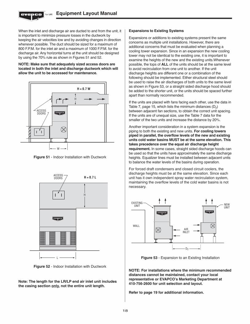
Indoor Installations
Occasionally, centrifugal fan cooling towers are installed indoorswhere they normally require ductwork to and from the unit. Inthese instances, the fan motor size and fan speed must beincreased due to the external static pressure imposed by theductwork. Most centrifugal fan towers can handle up to 1⁄2” ofexternal static pressure by increasing the fan motor one size witha corresponding increase in fan speed. For cases where externalstatic pressure exceeds 1⁄2”, the tower manufacturer should beconsulted. In all cases, the manufacturer must be advised whatexternal static pressure the unit will be subjected to so that thefan motors and drives can be properly sized.
The outside air for the unit can travel from a louver or slottedopening either through ductwork or by having the room act as aplenum. In the second case, where the room is acting like aplenum (Figure 50), the air velocity through the louvers feedingair to the unit should be limited to a maximum of 800 F.P.M.When a room is used as a plenum, other equipment may belocated in front of the air inlets. This equipment should not becloser than the minimum distances shown below.
Single Fan Sided Units
4’ and 5’ Wide Models - 3 feet8’ and 3m Wide Models - 5 feet12’ Wide Models - 6 feet
LR/LP - End Air Inlet Units
3’ Wide Models - 4 feet5’ Wide x 6’ Long Models - 4 feet5’ Wide x 9’ & 12’ Long Models - 5 feet8’ Wide Models - 6 feet
18
for LIFE Equipment Layout Manual
When the inlet and discharge air are ducted to and from the unit, itis important to minimize pressure losses in the ductwork bykeeping the air velocities low and by avoiding changes in directionwhenever possible. The duct should be sized for a maximum of800 F.P.M. for the inlet air and a maximum of 1000 F.P.M. for thedischarge air. Any horizontal turns at the unit should be designedby using the 70% rule as shown in Figures 51 and 52.
NOTE: Make sure that adequately sized access doors arelocated in both the inlet and discharge ductwork which willallow the unit to be accessed for maintenance.
ACCESSDOORS
H = 0.7 W
W
H
Figure 51 - Indoor Installation with Ductwork
ACCESSDOORS H = 0.7 L
L
H
Figure 52 - Indoor Installation with Ductwork
Note: The length for the LR/LP end air inlet unit includesthe casing section only, not the entire unit length.
Expansions to Existing Systems
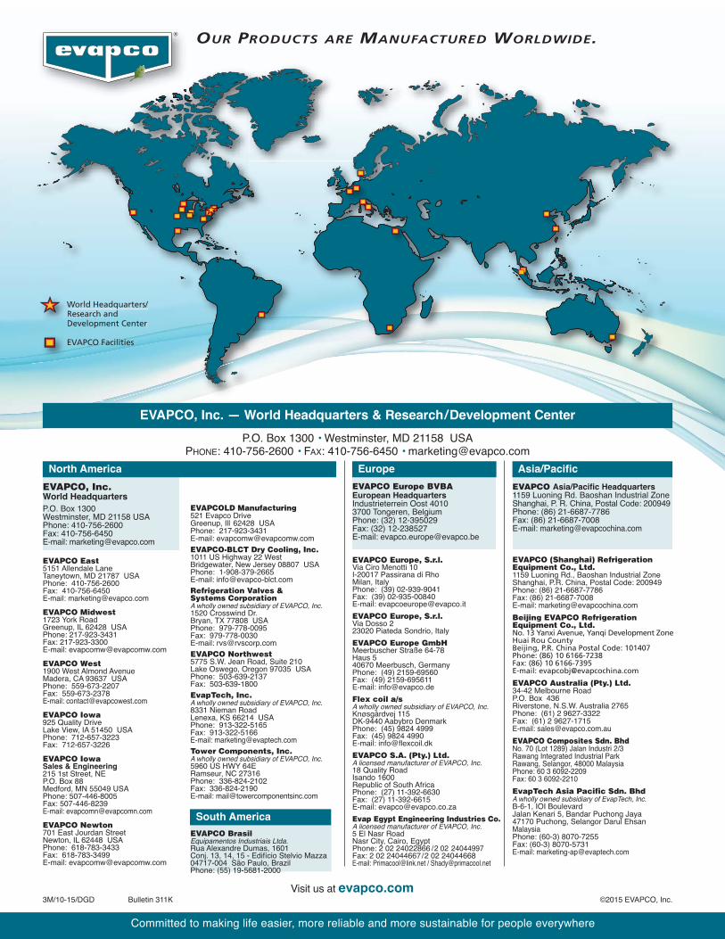
Expansions or additions to existing systems present the sameconcerns as multiple unit installations. However, there areadditional concerns that must be evaluated when planning acooling tower expansion. Since in an expansion the new coolingtower may not be identical to the existing one, it is important toexamine the heights of the new and the existing units.Wheneverpossible, the tops of ALL of the units should be at the same levelto avoid recirculation from one unit to another. If the unitdischarge heights are different one or a combination of thefollowing should be implemented. Either structural steel shouldbe used to raise the air discharges of both units to the same levelas shown in Figure 53, or a straight sided discharge hood shouldbe added to the shorter unit, or the units should be spaced furtherapart than normally recommended.
If the units are placed with fans facing each other, use the data inTable 7, page 15, which lists the minimum distances (D2)between adjacent fan sections, to obtain the correct unit spacing.If the units are of unequal size, use the Table 7 data for thesmaller of the two units and increase the distance by 20%.
Another important consideration in a system expansion is thepiping to both the existing and new units. For cooling towerspiped in parallel, the overflow levels of the new and existingunits cold water basins MUST be at the same elevation. Thistakes precedence over the equal air discharge heightrequirement. In some cases, straight sided discharge hoods canbe used so that the units have approximately the same dischargeheights. Equalizer lines must be installed between adjacent unitsto balance the water levels of the basins during operation.
For forced draft condensers and closed circuit coolers, thedischarge heights must be at the same elevation. Since eachunit has it own independent spray water recirculation system,maintaining the overflow levels of the cold water basins is notnecessary.
AIRINLET
EXISTINGUNIT
WALL
D2
NEWUNIT
Figure 53 - Expansion to an Existing Installation
NOTE: For installations where the minimum recommendeddistances cannot be maintained, contact your localrepresentative or EVAPCO’s Marketing Department at 410-756-2600 for unit selection and layout.
Refer to page 19 for additional information.
19
In our discussion of locating cooling towers, closed circuitcoolers, and condensers, our concern has been to provideadequate fresh air to the unit and minimize the potential forrecirculation. However, there are several other criteria whichalso must be considered before determining the final layout ofthe units.The cooling tower installation shall provide adequatespace for maintenance and the associated piping.
Space Requirements for Maintenance
When a unit is located in close proximity to other structures, wallsor equipment, there are minimum clearances required for peri-odic maintenance.Proper access must be provided for:
1) Adjustment and replacement of drive belts2) Lubrication of fan shaft bearings3) Cleaning of the water distribution system4) Access to the cold water basin for cleaning5) Access to the pumps of closed circuit coolers and condensers
for maintenance.
The minimum dimensions for service are shown for forced draftunits (Figures 54 & 55) and induced draft counterflow units(Figure 56) and crossflow units (Figure 57) and apply for allinstallations i.e., single units, multiple units, units in enclosures,etc. A unit which is located so that the periodic routinemaintenance can be accomplished easily will receive the propercare. A unit that does not have adequate space for maintenanceand is hard to service will NOT get proper care which willreduce its performance and useful life.
Other Layout Criteria
Figure 54 - Minumum Clearance Dimensions Forced Draft Units
M
3'
3'
3'
Varies*
AIRINLET
* SEE TABLE 6
Figure 55 - Minumum Clearance Dimensions Forced Draft Units(LR/LP - End Air Inlet)
Also, in addition to the periodic maintenance items, unit drawingsmust be reviewed to ensure there is room for any future majorrepair work. Space should be provided to allow for thereplacement of a fan motor, pump, fan, or fan shaft.
Space Requirements for Unit Piping
The piping design for each installation can be an importantaspect in locating evaporative cooling equipment. There are twokey piping considerations which should always be reviewed.
A. Sufficient Unit Elevation
The location of a unit is often influenced by the piping design.Adequate unit elevation is required to prevent pump cavitationand provide free drainage of the water from the cold water basin.When locating an evaporative condenser, the height required forpiping is particularly important. Unit elevation must be sufficient toprovide adequate height for the trapped liquid line and the slopingof the drain line leading to the high pressure receiver. Foradditional information concerning refrigeration pipe sizing andlayout, see EVAPCO Bulletin 131A “Piping EvaporativeCondensers.”
B. Spacing for Future Expansion
Space for piping of additional units should be reserved in the initialplan. When installing a single unit, it is important to consider whereadditional units would be placed and locate the single unit so thatfuture expansion will be as simple as possible. If the expansion isplanned in the near future, it is normally more economical to installbranch connections with valves during the initial installation ratherthan with the expansion. Not only should room for piping the futureunit be considered but, also the layout should be treated as amultiple unit installation with the required spacing that will allowproper airflow for the existing and possible future units.
3.5'VARIES*
VARIES*3.5'
* SEE TABLE 4
Figure 57 - Minumum Clearance Dimensions Induced Draft Crossflow Units
Figure 56 - Minumum Clearance Dimensions Induced Draft Counterflow Units
World Headquarters/Research and Development Center
EVAPCO Facilities
WReD
OUR PRODUCTS ARE MANUFACTURED WORLDWIDE.
Visit us at evapco.com3M/10-15/DGD Bulletin 311K ©2015 EVAPCO, Inc.
EVAPCO, Inc. — World Headquarters & Research/Development Center
P.O. Box 1300 • Westminster, MD 21158 USAPHONE: 410-756-2600 • FAX: 410-756-6450 • [email protected]
EVAPCO, Inc.World Headquarters
P.O. Box 1300Westminster, MD 21158 USAPhone: 410-756-2600Fax: 410-756-6450E-mail: [email protected]
Asia/Pacific
EVAPCO Asia/Pacific Headquarters1159 Luoning Rd. Baoshan Industrial ZoneShanghai, P. R. China, Postal Code: 200949Phone: (86) 21-6687-7786Fax: (86) 21-6687-7008E-mail: [email protected]
Europe
EVAPCO Europe BVBAEuropean HeadquartersIndustrieterrein Oost 40103700 Tongeren, BelgiumPhone: (32) 12-395029Fax: (32) 12-238527E-mail: [email protected]
EVAPCO East5151 Allendale LaneTaneytown, MD 21787 USAPhone: 410-756-2600Fax: 410-756-6450E-mail: [email protected]
EVAPCO Midwest1723 York RoadGreenup, IL 62428 USAPhone: 217-923-3431Fax: 217-923-3300E-mail: [email protected]
EVAPCO West1900 West Almond AvenueMadera, CA 93637 USAPhone: 559-673-2207Fax: 559-673-2378E-mail: [email protected]
EVAPCO Iowa925 Quality DriveLake View, IA 51450 USAPhone: 712-657-3223Fax: 712-657-3226
EVAPCO IowaSales & Engineering215 1st Street, NEP.O. Box 88Medford, MN 55049 USAPhone: 507-446-8005Fax: 507-446-8239E-mail: [email protected]
EVAPCO Newton701 East Jourdan StreetNewton, IL 62448 USAPhone: 618-783-3433Fax: 618-783-3499E-mail: [email protected]
EVAPCOLD Manufacturing521 Evapco DriveGreenup, Ill 62428 USA Phone: 217-923-3431E-mail: [email protected]
EVAPCO-BLCT Dry Cooling, Inc.1011 US Highway 22 WestBridgewater, New Jersey 08807 USA Phone: 1-908-379-2665E-mail: [email protected]
Refrigeration Valves & Systems CorporationA wholly owned subsidiary of EVAPCO, Inc.1520 Crosswind Dr.Bryan, TX 77808 USAPhone: 979-778-0095Fax: 979-778-0030E-mail: [email protected]
EVAPCO Northwest5775 S.W. Jean Road, Suite 210Lake Oswego, Oregon 97035 USAPhone: 503-639-2137Fax: 503-639-1800
EvapTech, Inc.A wholly owned subsidiary of EVAPCO, Inc.8331 Nieman RoadLenexa, KS 66214 USAPhone: 913-322-5165Fax: 913-322-5166E-mail: [email protected]
Tower Components, Inc.A wholly owned subsidiary of EVAPCO, Inc.5960 US HWY 64ERamseur, NC 27316Phone: 336-824-2102Fax: 336-824-2190E-mail: [email protected]
EVAPCO Europe, S.r.l.Via Ciro Menotti 10I-20017 Passirana di RhoMilan, ItalyPhone: (39) 02-939-9041Fax: (39) 02-935-00840E-mail: [email protected]
EVAPCO Europe, S.r.l.Via Dosso 223020 Piateda Sondrio, Italy
EVAPCO Europe GmbHMeerbuscher Straße 64-78Haus 540670 Meerbusch, GermanyPhone: (49) 2159-69560Fax: (49) 2159-695611E-mail: [email protected]
Flex coil a/sA wholly owned subsidiary of EVAPCO, Inc.Knøsgårdvej 115DK-9440 Aabybro DenmarkPhone: (45) 9824 4999Fax: (45) 9824 4990E-mail: [email protected]
EVAPCO S.A. (Pty.) Ltd.A licensed manufacturer of EVAPCO, Inc.18 Quality RoadIsando 1600Republic of South AfricaPhone: (27) 11-392-6630Fax: (27) 11-392-6615E-mail: [email protected]
Evap Egypt Engineering Industries Co.A licensed manufacturer of EVAPCO, Inc.5 El Nasr RoadNasr City, Cairo, EgyptPhone: 2 02 24022866 /2 02 24044997Fax: 2 02 24044667/2 02 24044668E-mail: [email protected] / [email protected]
EVAPCO (Shanghai) Refrigeration Equipment Co., Ltd.1159 Luoning Rd., Baoshan Industrial ZoneShanghai, P.R. China, Postal Code: 200949Phone: (86) 21-6687-7786Fax: (86) 21-6687-7008E-mail: [email protected]
Beijing EVAPCO Refrigeration Equipment Co., Ltd.No. 13 Yanxi Avenue, Yanqi Development ZoneHuai Rou CountyBeijing, P.R. China Postal Code: 101407Phone: (86) 10 6166-7238Fax: (86) 10 6166-7395E-mail: [email protected]
EVAPCO Australia (Pty.) Ltd.34-42 Melbourne RoadP.O. Box 436Riverstone, N.S.W. Australia 2765Phone: (61) 2 9627-3322Fax: (61) 2 9627-1715E-mail: [email protected]
EVAPCO Composites Sdn. BhdNo. 70 (Lot 1289) Jalan Industri 2/3Rawang Integrated Industrial ParkRawang, Selangor, 48000 MalaysiaPhone: 60 3 6092-2209Fax: 60 3 6092-2210
EvapTech Asia Pacific Sdn. BhdA wholly owned subsidiary of EvapTech, Inc.B-6-1, IOI BoulevardJalan Kenari 5, Bandar Puchong Jaya47170 Puchong, Selangor Darul EhsanMalaysiaPhone: (60-3) 8070-7255Fax: (60-3) 8070-5731E-mail: [email protected]
North America
South America
EVAPCO BrasilEquipamentos Industriais Ltda.Rua Alexandre Dumas, 1601Conj. 13, 14, 15 - Edifício Stelvio Mazza04717-004 São Paulo, BrazilPhone: (55) 19-5681-2000
Committed to making life easier, more reliable and more sustainable for people everywhere


![[PPT]EVAPCO, INC. - Mr. GoodTower de Méxicomrgoodtowerdemexico.com/presentations/ATBasicsSpanish.ppt · Web viewTitle EVAPCO, INC. Author John Kollasch Last modified by Max Duarte](https://static.documents.pub/doc/80x56/5ac243bb7f8b9ad73f8ddbd7/pptevapco-inc-mr-goodtower-de-mxic-viewtitle-evapco-inc-author-john-kollasch.jpg)


