37
1 Ford, Bacon & Davis, LLC Equipment Sizing and Specification: Shell and Tube Heat Exchangers Presented by: Damon Motto, P.E. (LA #36791)

1Ford, Bacon & Davis, LLC
Equipment Sizing and Specification:
Shell and Tube Heat Exchangers
Presented by: Damon Motto, P.E. (LA #36791)

• Safety Topic
• Heat Exchanger Geometry Fundamentals for Process Engineers
• Shell and Tube Heat Exchanger Design Software
• Process Engineering Workflow throughout the Project Cycle
• Demonstration
Ford, Bacon & Davis, LLC 2

Safety Topic:Don’t Let History Repeat Itself
3Ford, Bacon & Davis, LLC

• CEP Safety Beacon May 2016
Ford, Bacon & Davis, LLC 4
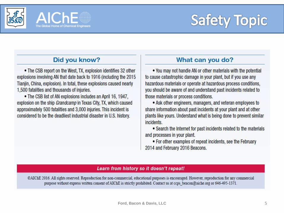
Ford, Bacon & Davis, LLC 5

Heat Exchanger Geometry Fundamentals for Process
Engineers
6Ford, Bacon & Davis, LLC

• Resources for nomenclature/diagrams/guidelines
– GPSA Databook Section 9
– Perry’s Section 11 (Heat Transfer Equipment)
– AIChE CEP or e-library
– Company or plant specific design guides
Ford, Bacon & Davis, LLC 7
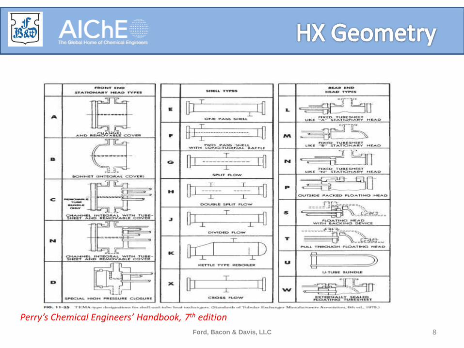
Ford, Bacon & Davis, LLC 8
Perry’s Chemical Engineers’ Handbook, 7th edition

Ford, Bacon & Davis, LLC 9
Perry’s Chemical Engineers’ Handbook, 7th edition

Ford, Bacon & Davis, LLC 10
Perry’s Chemical Engineers’ Handbook, 7th edition

Ford, Bacon & Davis, LLC 11
Perry’s Chemical Engineers’ Handbook, 7th edition

Ford, Bacon & Davis, LLC 12
Heat Exchanger Equipment Field Manual, Stewart and Lewis

Ford, Bacon & Davis, LLC 13
Effectively Design Shell and Tube Heat Exchangers, CEP Feb 1998, Mukherjee

Ford, Bacon & Davis, LLC 14
Quadrant or Segment
Ribbon
H-banded
COMMON TUBE PASS LAYOUTS

• Leakage streams– A stream
• Flow between the tube and the tube hole in the baffle. Not detrimental but B stream is better
– B stream• Not a “leakage stream”. This is where you want most of the flow
– C stream• Bundle bypass stream• Hard to visualize. Flows around outer edge of the baffle.
– E stream • Baffle to shell leakage. Flow that slips between the baffle and the shell
– F stream• Pass partition leakage. Flow down/across the pass partition
Ford, Bacon & Davis, LLC 15
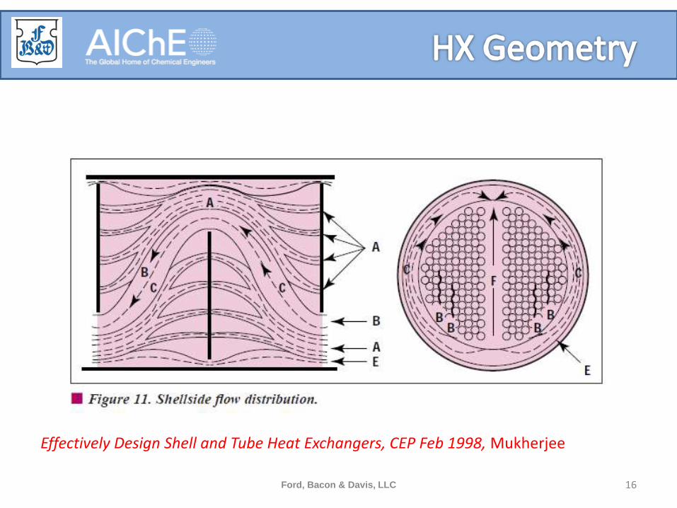
Ford, Bacon & Davis, LLC 16
Effectively Design Shell and Tube Heat Exchangers, CEP Feb 1998, Mukherjee

• Fouling
– Usually accounted for in a fouling factor
• Fouling resistance on tube and shell
– Can be combined as a Total Equivalent Fouling Resistance (TEFR)
– Sometimes an “oversurface” factor is applied to area for fouling
– Carefully choose fouling factors to prevent oversizing
– Multiple fouling mechanisms but in general higher velocity leads to less fouling
Ford, Bacon & Davis, LLC 17

Shell and Tube Heat Exchanger Design Software
18Ford, Bacon & Davis, LLC

• Software can be packaged as a suite of products. • Shell and Tube design and rating
• Tube vibration analysis
• Air Cooler design and rating
• Others
– Plate and frame, plate-fin, spiral plate, hairpin, jacketed pipe, and fired heater, etc.
• This presentation focuses on thermal and hydraulic design of shell and tube heat exchangers
Ford, Bacon & Davis, LLC 19
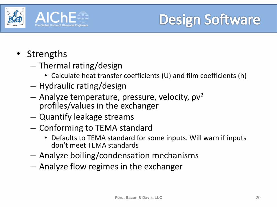
• Strengths– Thermal rating/design
• Calculate heat transfer coefficients (U) and film coefficients (h)
– Hydraulic rating/design– Analyze temperature, pressure, velocity, ρv2
profiles/values in the exchanger– Quantify leakage streams– Conforming to TEMA standard
• Defaults to TEMA standard for some inputs. Will warn if inputs don’t meet TEMA standards
– Analyze boiling/condensation mechanisms– Analyze flow regimes in the exchanger
Ford, Bacon & Davis, LLC 20

• Weaknesses (of the thermal/hydraulic module)– Mechanical
• Do not trust mechanical calculations (tube, shell, nozzle, tubesheet thicknesses)
• Have mechanical engineer check calculations• In general, these calculations and warnings seem to be conservative
– Vibration• With a few exceptions, vibration analysis in shell and tube modules is
conservative. If no warnings, then typically there is low risk of vibration issues.
• Vibration warnings for existing exchangers should be investigated further (possibly FEA software).
– Piping hydraulics (Reboilers only)• Recommend to check flow regimes and pressure drop calculations
using other methods
Ford, Bacon & Davis, LLC 21
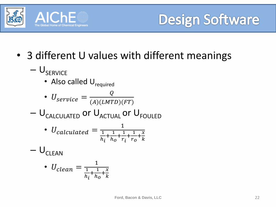
• 3 different U values with different meanings– USERVICE
• Also called Urequired
• 𝑈𝑠𝑒𝑟𝑣𝑖𝑐𝑒 =𝑄
(𝐴)(𝐿𝑀𝑇𝐷)(𝐹𝑇)
– UCALCULATED or UACTUAL or UFOULED
• 𝑈𝑐𝑎𝑙𝑐𝑢𝑙𝑎𝑡𝑒𝑑 =1
1
ℎ𝑖+
1
ℎ𝑜+1
𝑟𝑖+
1
𝑟𝑜+𝑥
𝑘
– UCLEAN
• 𝑈𝑐𝑙𝑒𝑎𝑛 =1
1
ℎ𝑖+
1
ℎ𝑜+𝑥
𝑘
Ford, Bacon & Davis, LLC 22

• Typically, software can be run in different modes
– Design Mode
• Based on a minimum number of inputs, will vary shell diameter, baffle spacing, tubepasses, tube length, etc.
• Will run short cut calculations on every possible combination and output a table with results
• Pick the best option, and run rigorous calculations in Rating mode
Ford, Bacon & Davis, LLC 23

– Rating Mode• Specify exchanger inlet conditions and outlet conditions
of one side– Alternately, overall duty can be specified instead of outlet
condition
• Used to evaluate existing exchanger or quantify new exchanger overdesign
• Based on a given geometry, calculates all three U values
• 𝑂𝑣𝑒𝑟𝑑𝑒𝑠𝑖𝑔𝑛 =𝑈𝑐𝑎𝑙𝑐𝑢𝑙𝑎𝑡𝑒𝑑
𝑈𝑠𝑒𝑟𝑣𝑖𝑐𝑒− 1 𝑥100%
• Note that overdesign and Total Equivalent Fouling Resistance (TEFR) are not the same.
Ford, Bacon & Davis, LLC 24

– Simulation Mode• Specify exchanger inlet conditions
– Has one less degree of freedom than Rating mode
• Used to estimate how exchanger will perform at a certain set of process conditions or degree of fouling
• Very useful for relief calculations
• Program will iterate until overdesign is zero– Usually converges to +/- 2% overdesign
– 𝑈𝑐𝑎𝑙𝑐𝑢𝑙𝑎𝑡𝑒𝑑 = 𝑈𝑠𝑒𝑟𝑣𝑖𝑐𝑒
–𝑄
(𝐴)(𝐿𝑀𝑇𝐷)(𝐹𝑇)=
11
ℎ𝑖+
1
ℎ𝑜+1
𝑟𝑖+
1
𝑟𝑜+𝐿
𝑘
Ford, Bacon & Davis, LLC 25

• Specifying fluid and thermodynamic properties– User specified grid
• Table of Properties vs.. Temperature are given at multiple pressures.• Program will interpolate. Specify pressures and temperatures that bracket the
operating conditions (both bulk and tube wall) to prevent extrapolation. • Manually type in properties• Copy/paste from Excel• Import from process simulation software
– Input composition and generate properties through simulator Thermo engine– Select a stream from an existing simulation
– Program Calculated• Composition is input into program • Choose between design software thermo or attach thermo from process
simulation• Software will calculate all the properties it requires as the program is run• This option typically requires more calculation time.
Ford, Bacon & Davis, LLC 26
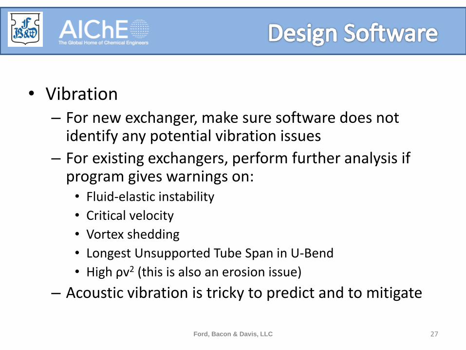
• Vibration– For new exchanger, make sure software does not
identify any potential vibration issues
– For existing exchangers, perform further analysis if program gives warnings on:• Fluid-elastic instability
• Critical velocity
• Vortex shedding
• Longest Unsupported Tube Span in U-Bend
• High ρv2 (this is also an erosion issue)
– Acoustic vibration is tricky to predict and to mitigate
Ford, Bacon & Davis, LLC 27

Process Engineering Workflow throughout the Project Cycle
28Ford, Bacon & Davis, LLC
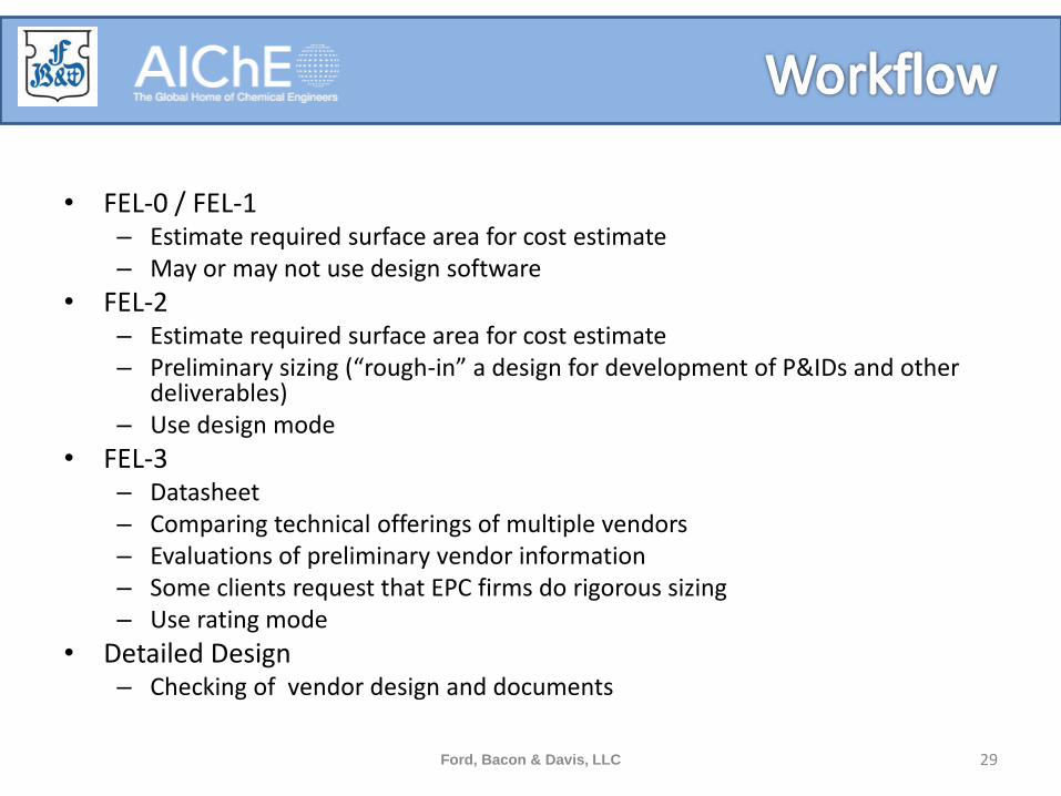
• FEL-0 / FEL-1– Estimate required surface area for cost estimate– May or may not use design software
• FEL-2– Estimate required surface area for cost estimate– Preliminary sizing (“rough-in” a design for development of P&IDs and other
deliverables)– Use design mode
• FEL-3– Datasheet– Comparing technical offerings of multiple vendors– Evaluations of preliminary vendor information– Some clients request that EPC firms do rigorous sizing– Use rating mode
• Detailed Design– Checking of vendor design and documents
Ford, Bacon & Davis, LLC 29

• FEL-0 / FEL-1
– Use heat and mass balance or simulation for duty and LMTD
– Use tables in Perry’s, GPSA, etc. for typical U values
– Calculate surface area
• Q=UA(LMTD)
• 𝐴 =𝑄
(𝑈)(𝐿𝑀𝑇𝐷)
– Alternately, use quick sizing tool in process simulation if typical value can’t be found
Ford, Bacon & Davis, LLC 30

• FEL-2– For simple exchangers,
• Fill out datasheet• Update any calculations from FEL-1 based on updated heat and mass
balance, etc.• Can use the same typical U value as before or can run design software
to get a better estimate
– For more complex exchangers,• like thermosiphons, heat exchangers in networks, any fluids with skin
temperature limits, applications with 2-phase flow, etc., • Run a very preliminary design software calculation to start developing
what the exchanger will look like on P&IDs (e.g. number of shells in parallel/series, temperature control scheme, etc.)
• Run off-design cases in rating/simulation mode to troubleshoot possible issues
• This can help to head off any issues that may come as a surprise later
Ford, Bacon & Davis, LLC 31

• FEL-3/Detailed Design– For most clients, at this point the vendor does the
heavy lifting and EPC firm reviews and check-rates the vendor drawings
– Some clients prefer that the EPC firm process and/or mechanical engineers do extensive work on exchanger design to fully specify the exchanger (e.g. tubes, baffles, shell size, tie rods, sealing strips, skid bars, etc.). The vendor receives the design, develops drawings, and builds the exchanger. Be careful to explicitly state who, if anyone, will provide thermal or hydraulic guarantee
Ford, Bacon & Davis, LLC 32

Demonstration
33Ford, Bacon & Davis, LLC

• Demonstration
– Design of E-4 in HYSYS Example File “MODELING A CRUDE VACUUM SYSTEM WITH PREHEAT TRAIN.hsc”
– Crude vs. Diesel Product Exchanger
– TEMA Type AES
– 1” BWG 12 tubes
– Diesel fouling factor = 0.0015 hr-sqft-F/Btu
– Crude fouling factor = 0.003 hr-sqft-F/Btu
Ford, Bacon & Davis, LLC 34
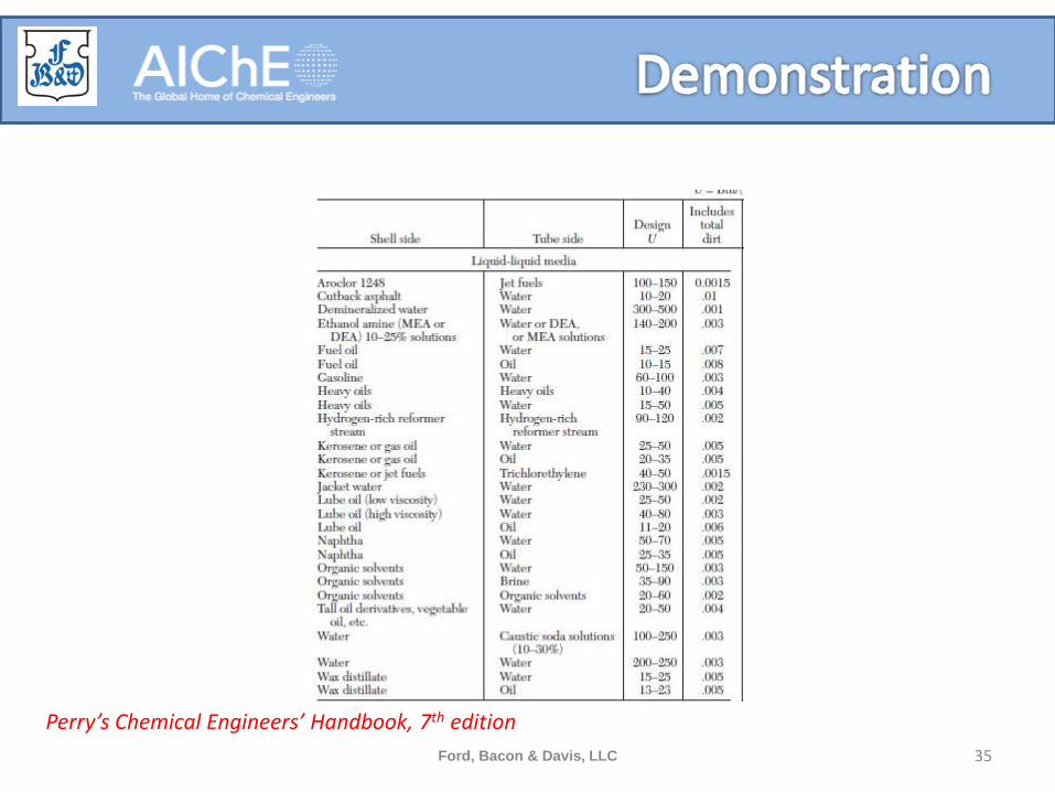
Ford, Bacon & Davis, LLC 35
Perry’s Chemical Engineers’ Handbook, 7th edition

• Estimate area with typical U• U = 20 to 35 Btu/F-sqft-hr
– Q=10.4 MMBTUH, LMTD=320 F
– A= 929 to 1625 sq. ft (plus design margin)
• Use quick sizing tool
• Use design software in design mode
Ford, Bacon & Davis, LLC 36
Questions, Comments, or Suggestions?
Email: [email protected]: (504) 412-7469
Cell: (516) 680-5115
37Ford, Bacon & Davis, LLC


