Equipments Design Equipments Design Production of Synthesis Gas Production of Synthesis Gas from Natural Gas by Steam from Natural Gas by Steam Reforming Reforming Supervised By: Supervised By: Prof. Mohamed A. Fahim Prof. Mohamed A. Fahim Eng. Yusuf Ismail Ali Eng. Yusuf Ismail Ali Presented By: Presented By: Latifa AL-Qabandi Latifa AL-Qabandi
Transcript
Equipments Design Equipments Design Production of Synthesis Production of Synthesis Gas from Natural Gas by Gas from Natural Gas by
Packed Stripper DesignPacked Stripper Design Stripping is a physical Stripping is a physical separation processseparation process where where
one or more components are removed from a one or more components are removed from a liquid stream by a vapor stream.liquid stream by a vapor stream.
There are many different types of packing used There are many different types of packing used and each one has advantages and and each one has advantages and disadvantages.disadvantages.
More common packing materials are metal and More common packing materials are metal and plastic Pall rings, metal Michael Bialecki rings, plastic Pall rings, metal Michael Bialecki rings, and ceramic Intalox saddles.and ceramic Intalox saddles.
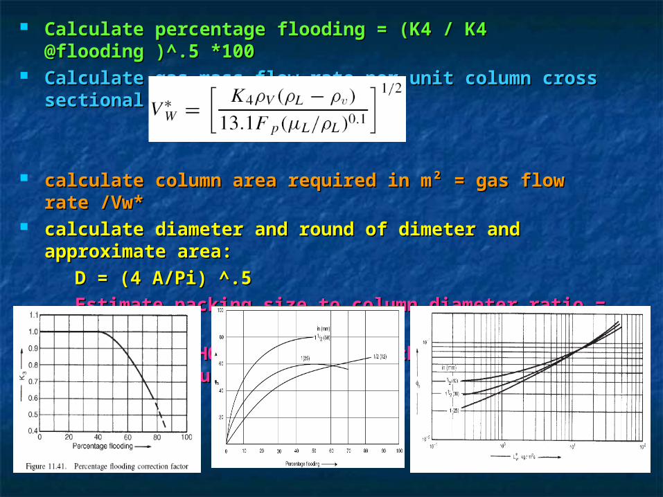
Calculate gas mass flow rate per unit column cross Calculate gas mass flow rate per unit column cross sectional area.sectional area.
calculate column area required in m² = gas flow rate calculate column area required in m² = gas flow rate /Vw*/Vw*
calculate diameter and round of dimeter and calculate diameter and round of dimeter and approximate area:approximate area:
D = (4 A/Pi) ^.5D = (4 A/Pi) ^.5
. . Estimate packing size to column diameter ratio = D/38E-Estimate packing size to column diameter ratio = D/38E-33
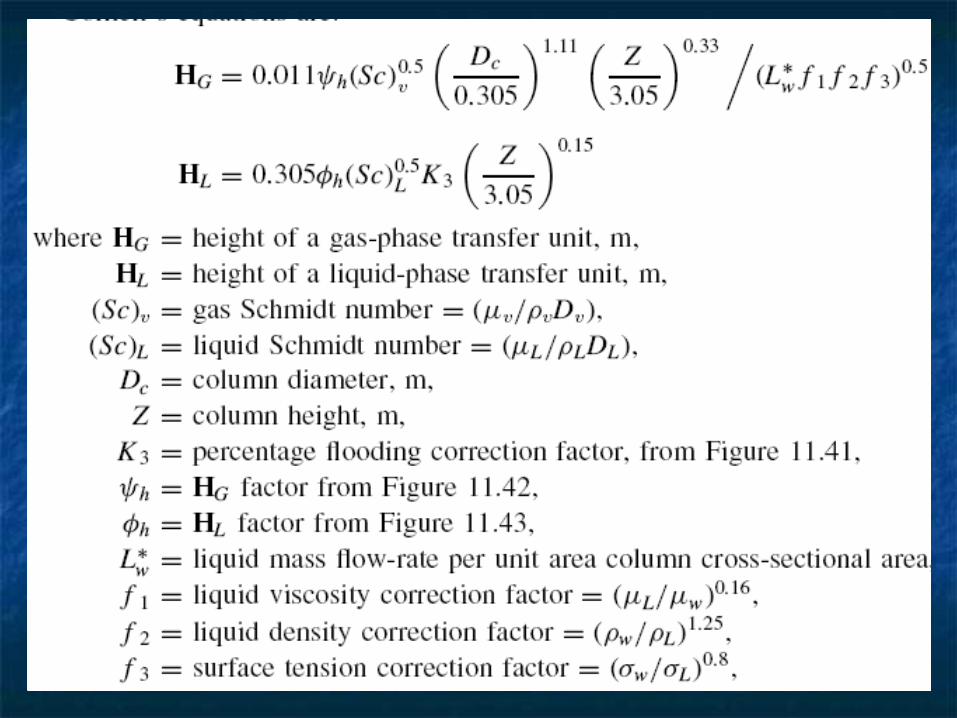
. Estimating HOG and height of the column using figures . Estimating HOG and height of the column using figures and equations:and equations:
then HOG = Hg + ( HL * mGm/Lm), and z = HOG * NOG.then HOG = Hg + ( HL * mGm/Lm), and z = HOG * NOG. Calculate the cost in $.Calculate the cost in $.
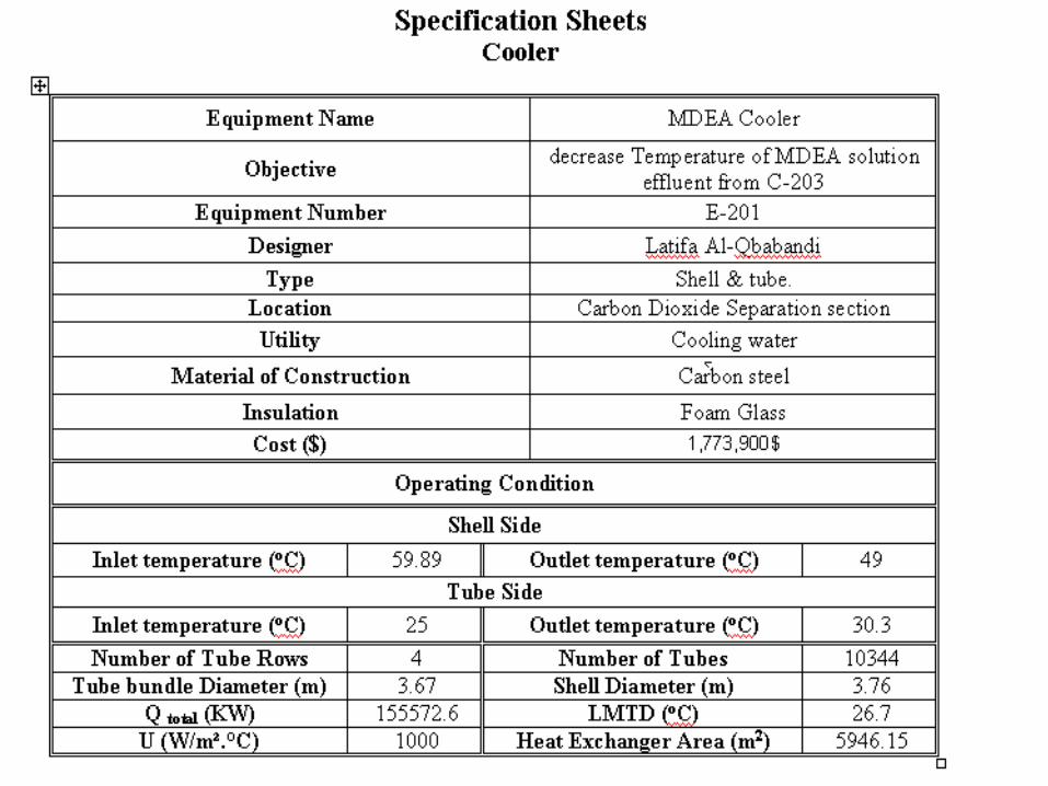
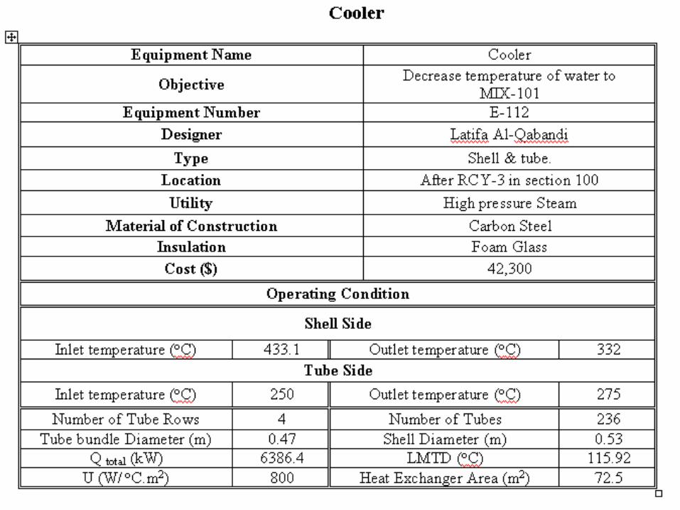
Specification SheetSpecification Sheet
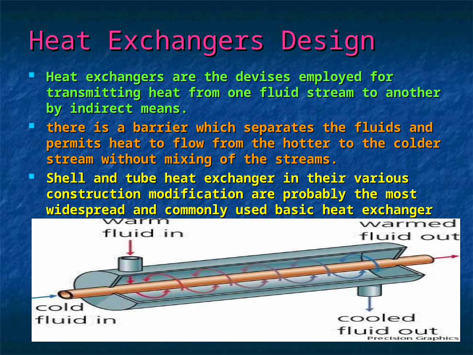
Heat Exchangers DesignHeat Exchangers Design Heat exchangers are the devises employed for Heat exchangers are the devises employed for
transmitting heat from one fluid stream to another transmitting heat from one fluid stream to another by indirect means.by indirect means.
there is a barrier which separates the fluids and there is a barrier which separates the fluids and permits heat to flow from the hotter to the colder permits heat to flow from the hotter to the colder stream without mixing of the streams.stream without mixing of the streams.
Shell and tube heat exchanger in their various Shell and tube heat exchanger in their various construction modification are probably the most construction modification are probably the most widespread and commonly used basic heat widespread and commonly used basic heat exchanger configuration in the process industries.exchanger configuration in the process industries.
Procedure:Procedure: Heat loadHeat load
Log mean temperatureLog mean temperature
. . Heat transfer areaHeat transfer area
. . Number of tubesNumber of tubes
hotphotcoldpcold TcMTcMQ
lmtm
lm
TFT
tT
ttS
tt
TTR
tTtT
tTtTT
11
12
12
21
12
21
1221
;
ln
mTU
QA
DensityPassArea
FlowRateuvelocity
areatoncrossPasstubespassArea
dareaSectioncross
sesAssumedPas
tubesPassTubes
ubeareaOfOneT
totalAreatubes
LdubeAreaOfOneT
t
i
o
*/
sec//
25.0
#/
#
**25.0
2
2
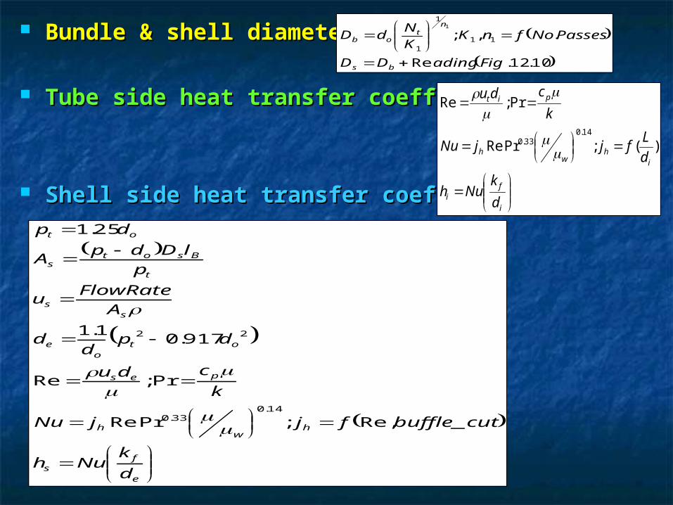
Bundle & shell diameterBundle & shell diameter
Tube side heat transfer coefficientTube side heat transfer coefficient
Shell side heat transfer coefficientShell side heat transfer coefficient
10.12.Re
.,; 11
1
1
1
FigadingDD
PassesNofnKK
NdD
bs
nt
ob
i
fi
ih
wh
pit
d
kNuh
d
LfjjNu
k
cdu
)(;PrRe
Pr;Re
14.033.0
e
fs
hw
h
pes
oto
e
ss
t
Bsots
ot
d
kNuh
cutbufflefjjNu
k
cdu
dpd
d
A
FlowRateu
p
lDdpA
dp
_Re,;PrRe
Pr;Re
917.01.1
25.1
14.033.0
22
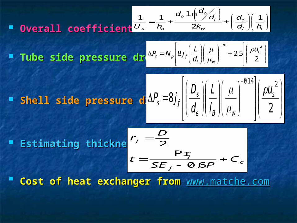
Overall coefficientOverall coefficient
Tube side pressure dropTube side pressure drop
Shell side pressure dropShell side pressure drop
Estimating thicknessEstimating thickness
Cost of heat exchanger fromCost of heat exchanger from www.matche.comwww.matche.com
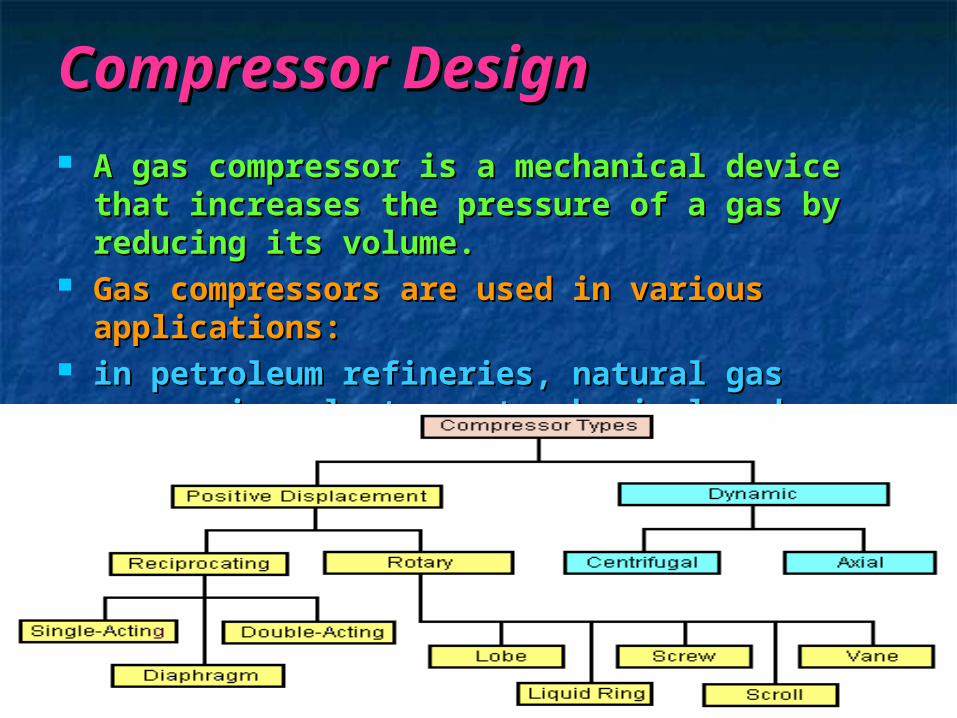
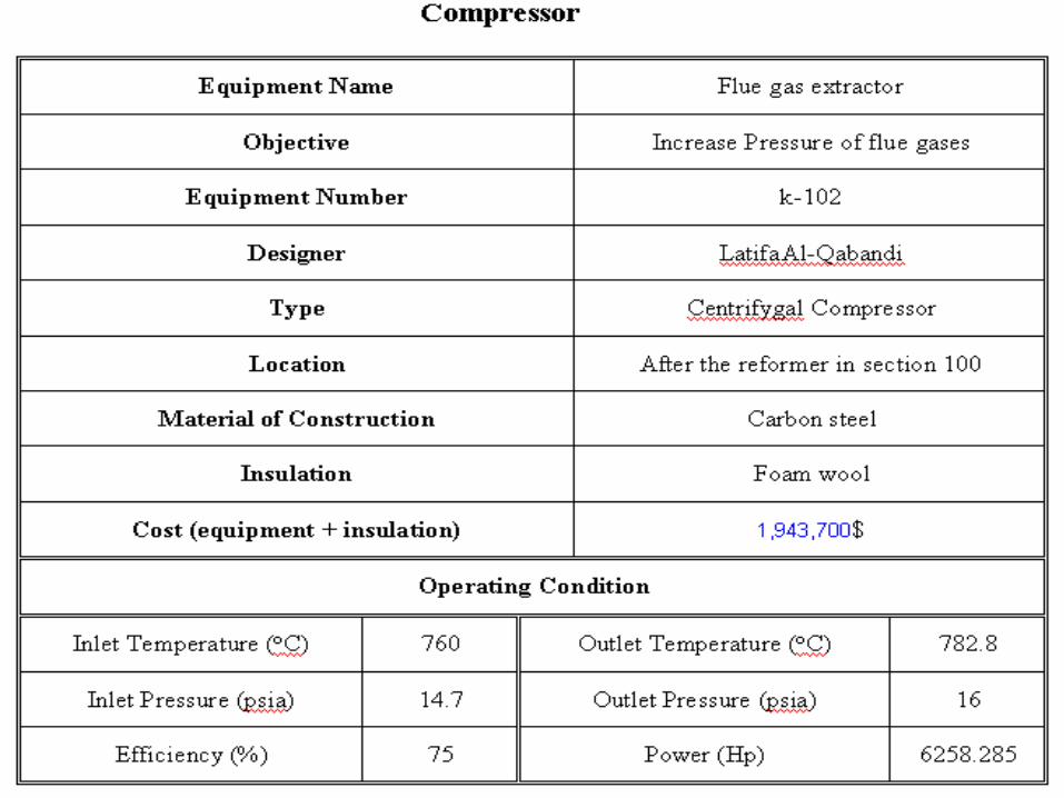
Compressor DesignCompressor Design A gas compressor is a mechanical device A gas compressor is a mechanical device
that increases the pressure of a gas by that increases the pressure of a gas by reducing its volume.reducing its volume.
Gas compressors are used in various Gas compressors are used in various applications:applications:
in petroleum refineries, natural gas in petroleum refineries, natural gas processing plants, petrochemical and processing plants, petrochemical and chemical plants.chemical plants.
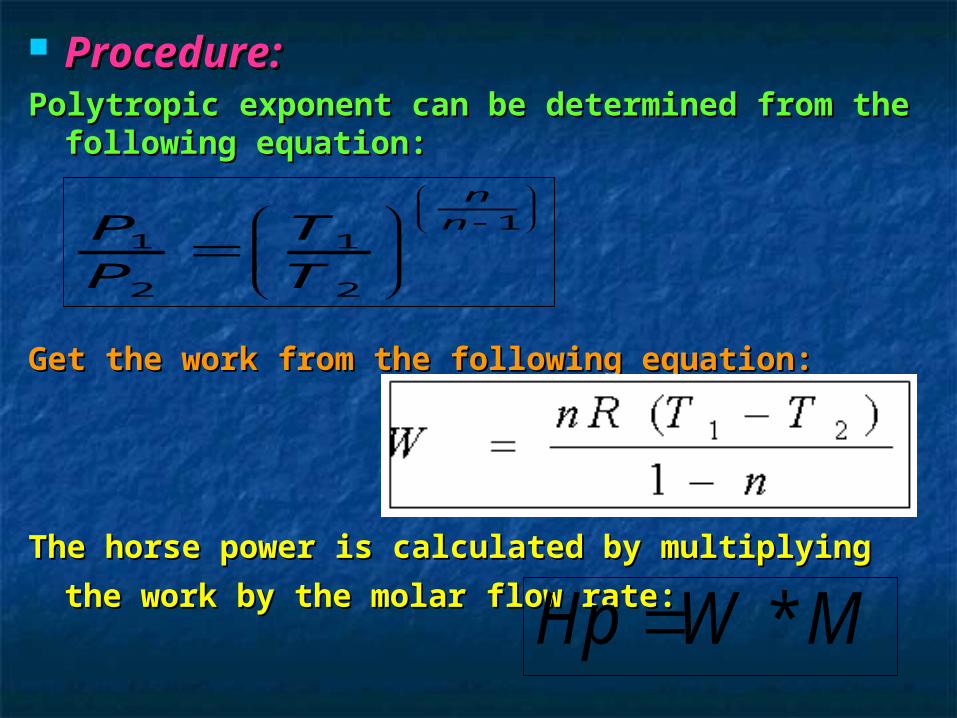
Procedure:Procedure:Polytropic exponent can be determined from the Polytropic exponent can be determined from the
following equation:following equation:
Get the work from the following equation:Get the work from the following equation:
The horse power is calculated by multiplying the The horse power is calculated by multiplying the
work by the molar flow rate:work by the molar flow rate:
11 1
2 2
n
nP T
P T
*Hp W M
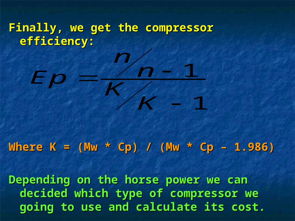
Finally, we get the compressor efficiency:Finally, we get the compressor efficiency:
Where K = (Mw * Cp) / (Mw * Cp – 1.986)Where K = (Mw * Cp) / (Mw * Cp – 1.986)
Depending on the horse power we can Depending on the horse power we can decided which type of compressor we decided which type of compressor we going to use and calculate its cost.going to use and calculate its cost.
1
1
nnEp
KK
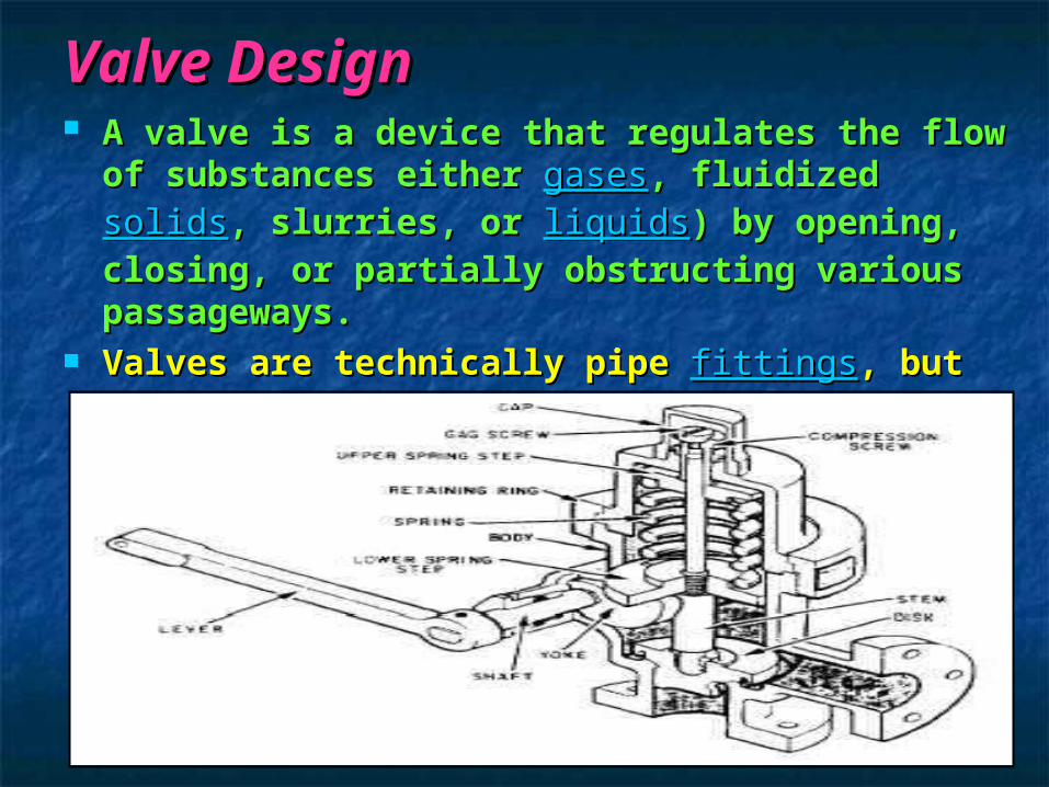
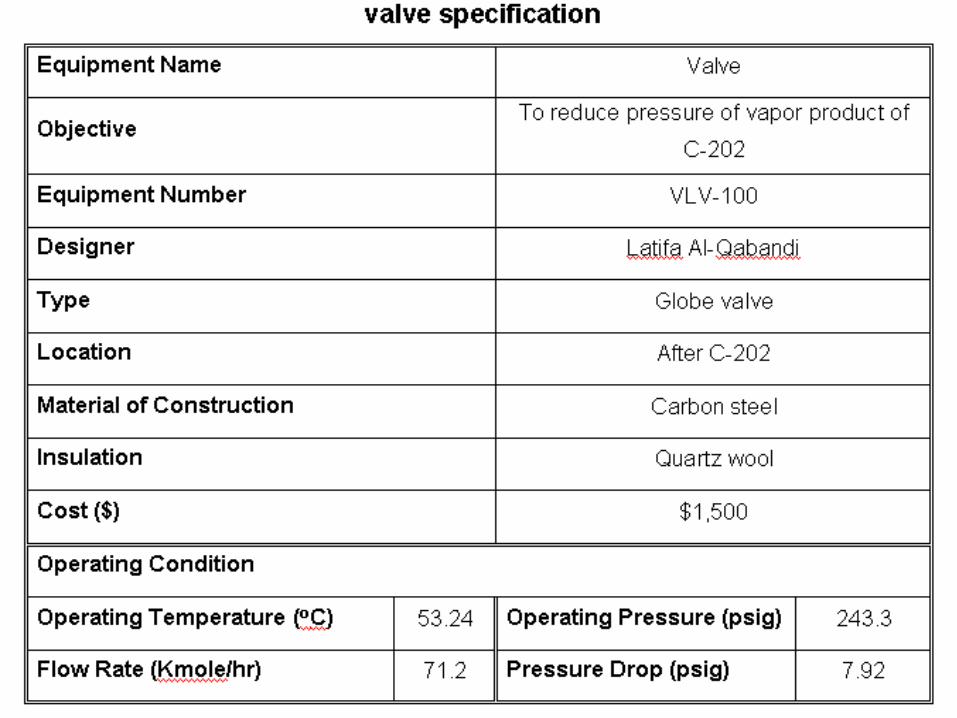
Valve DesignValve Design A valve is a device that regulates the flow of A valve is a device that regulates the flow of
substances either substances either gasesgases, fluidized , fluidized solidssolids, , slurries, or slurries, or liquidsliquids) by opening, closing, or ) by opening, closing, or partially obstructing various passageways. partially obstructing various passageways.
Valves are technically pipe Valves are technically pipe fittingsfittings, but , but usually are discussed separately.usually are discussed separately.