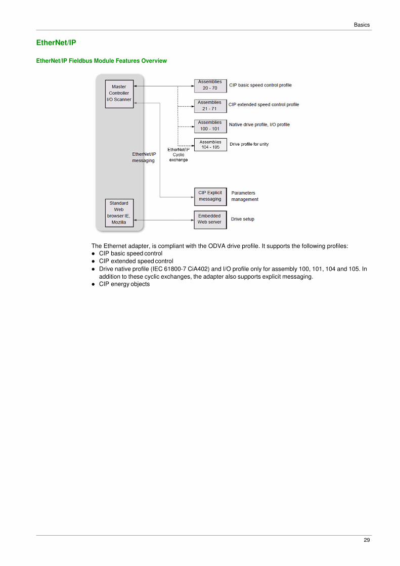
EtherNet/IP is a fieldbus based on TCP and UDP. EtherNet/IP extends Ethernet by an advanced industrial
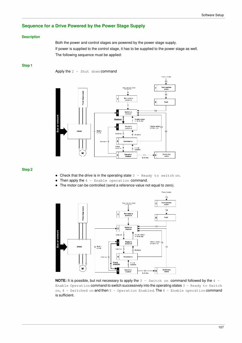
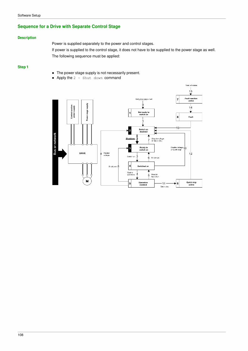
protocol (CIP, Common Industrial Protocol) as an application layer for automation applications in this way,
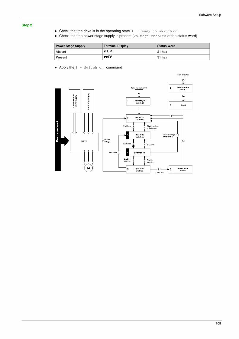
Ethernet suites for industrial control. Products from different manufacturers can be networked without the
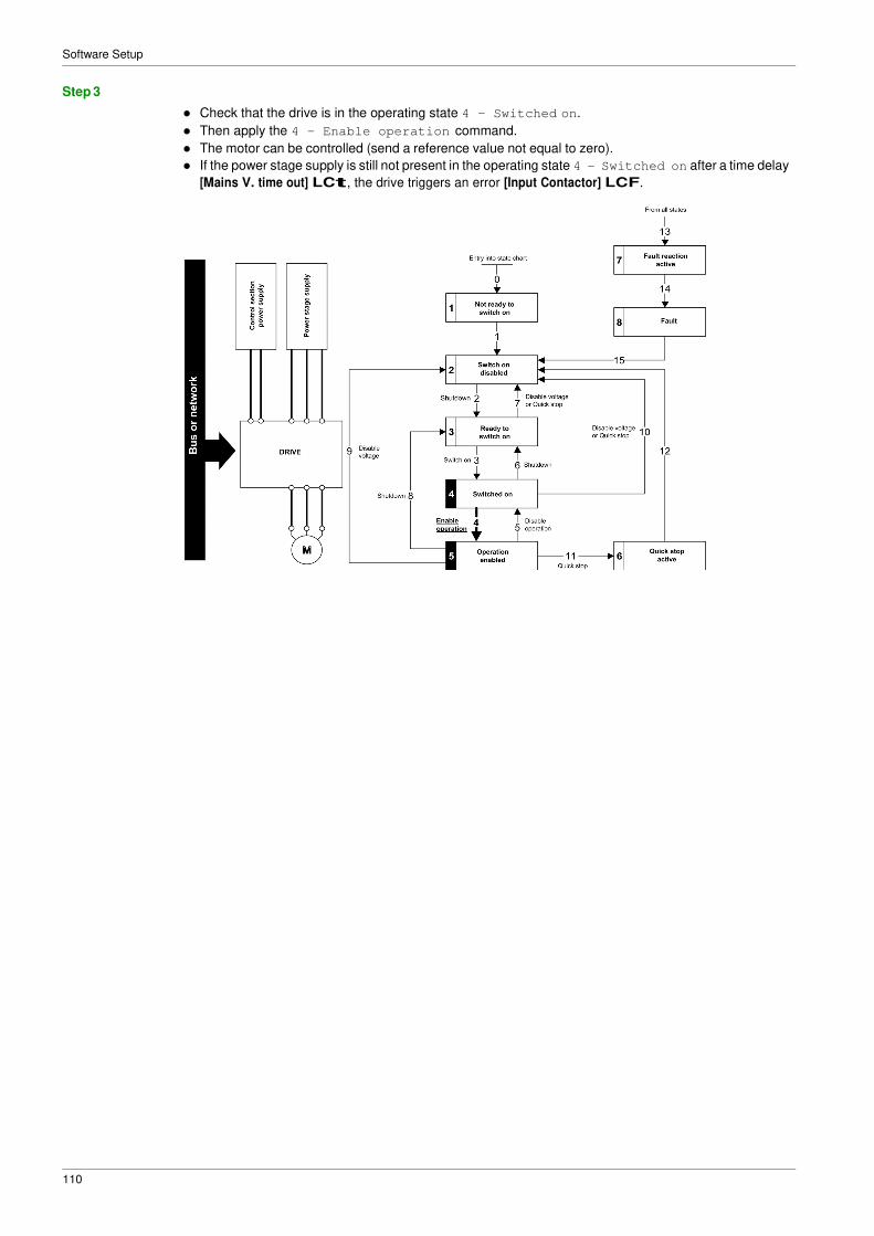
need for special interface adaptation.
TCP/IP and Ethernet Features
The product supports the following functions via:
� Manual IP address assignment
� Automatic IP address assignment via BOOTP or DHCP
� Automatic configuration data via FDR
� Commissioning via DTM-based commissioning software
� Diagnostics and configuration via integrated Web server
� Support of LLDP (Link Layer Discovery Protocol)
� Support of RSTP (Rapid Spanning Tree Protocol)
� Support of SNMP (Simple Network Management Protocol)
� Support of DNS (Domain Name System)
� Support of IPV6 for DPWS (Devices Profile for Web Services)
� Handling of QoS (Quality of Service)
Web Server
The standard webserver (in six languages) provides access to pages such as:
� My dashboard
� Display
� Diagnostics
� Drive
� Setup
MultiDrive Link Feature
The FK41 embeds, in addition of the features described above, the MultiDrive Link feature. This allow to use and give access to Multiple Pumps functions of ER41 range.
For more informations about commissioning of MultiDrive Link feature and Multiple Pumps functions, refer
to ER41 Programming Manual.
Basics
20
Network Layer Supported Functions/Protocols
ARP Protocol
The ARP (Address resolution protocol) is a protocol used to map network addresses (IP) to hardware
addresses (MAC).
The protocol operates below the network layer as a part of the OSI link layer, and is used when IP is used
over Ethernet. A host, wishing to obtain a physical address, broadcasts an ARP request onto the TCP/IP
network. A unique IP address is assigned to the host, and is sent to its hardware address.
ICMP Protocol
The FK41 Ethernet modules manage the ICMP protocol.
� ICMP client: not supported
� ICMP server: the managed requests are the following:
Type Description
0 Echo reply (ping)
3 Destination unreachable
4 Sources quench
5 Redirect
6 Alternate host address
8 Echo request (ping)
9 Router advertisement
10 Router solicitation
11 Time exceeded
12 Parameter problem
13 Time stamp request
14 Time stamp reply
15 Information request
16 Information reply
17 Address mask request
18 Address mask reply
IP Protocol
The Ethernet adapter implements the IPV4 and IPV6 (for DPWS) protocols.
SNMP Services
The Ethernet adapter accepts the community name “private” for writing and the community name “public”
for Reading.
MIB
Objects Description Access Default Value
SysDescr Text description of the product Read only BLEMO ER41 Ethernet TCP/IP
SysObjectID Points in the private MIB on the
product part number
Read only 1.3.6.1.4.1.3833.1.100.4.1
SysUpTime Time elapsed since the last power-
up
Read only Managed by the option
SysContact Information allowing to contact the
node manager
Read/write '' ''
SysName Node administrative name Read/write “” or FDR device name if configured
SysLocation Physical location of the product Read/write '' ''
SysService Indicates the service type offered by
the product.
Read only 72
Basics
21
TCP and UDP Protocol
Connections
The Ethernet adapter supports up to 32 concurrent TCP/IP and/or TCP/UDP connection.
BOOTP and DHCP Protocol
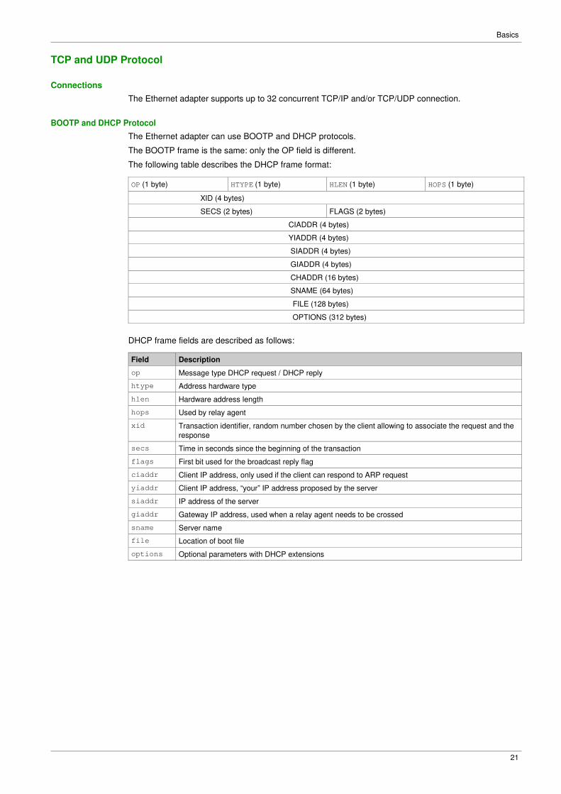
The Ethernet adapter can use BOOTP and DHCP protocols.
The BOOTP frame is the same: only the OP field is different.
The following table describes the DHCP frame format:
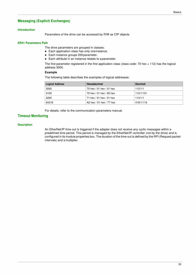
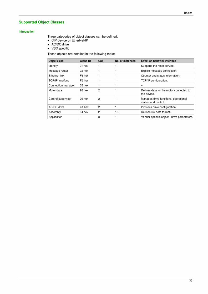
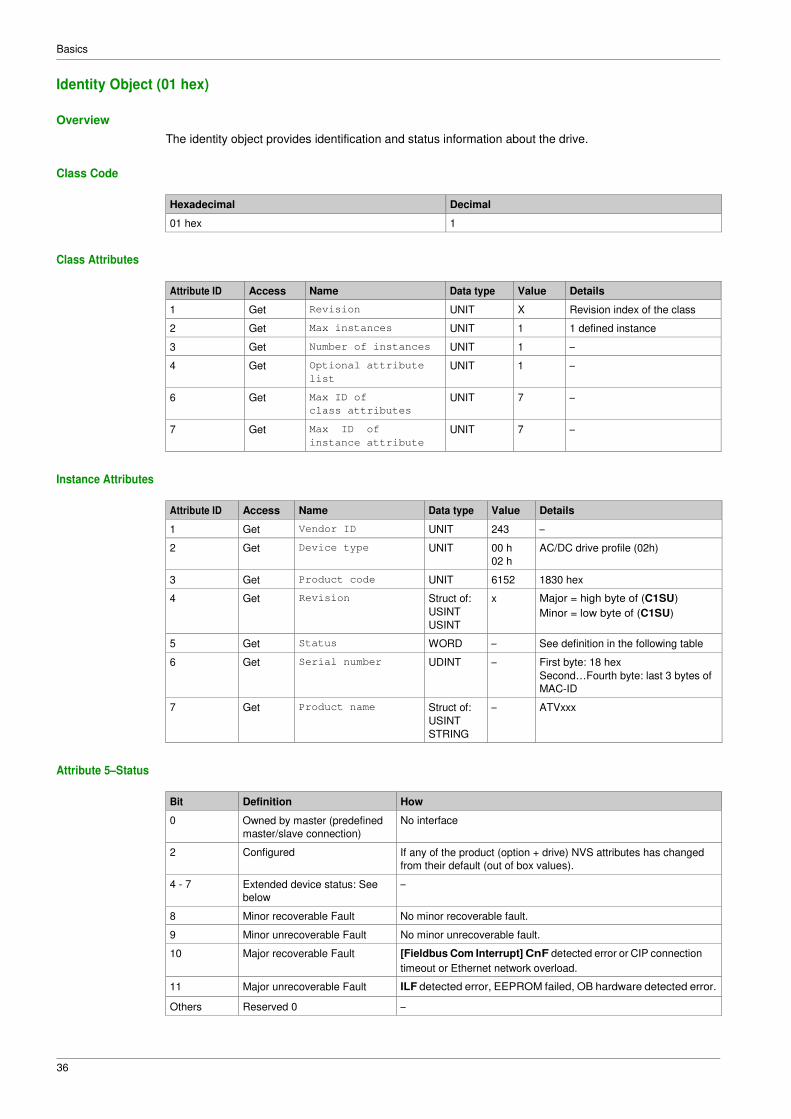
The identity object provides identification and status information about the drive.
Class Code
Hexadecimal Decimal
01 hex 1
Class Attributes
Attribute ID Access Name Data type Value Details
1 Get Revision UNIT X Revision index of the class
2 Get Max instances UNIT 1 1 defined instance
3 Get Number of instances UNIT 1 –
4 Get Optional attribute
list
UNIT 1 –
6 Get Max ID of
class attributes
UNIT 7 –
7 Get Max ID of
instance attribute
UNIT 7 –
Instance Attributes
Attribute ID Access Name Data type Value Details
1 Get Vendor ID UNIT 243 –
2 Get Device type UNIT 00 h
02 h
AC/DC drive profile (02h)
3 Get Product code UNIT 6152 1830 hex
4 Get Revision Struct of:
USINT
USINT
x Major = high byte of (C1SU)
Minor = low byte of (C1SU)
5 Get Status WORD – See definition in the following table
6 Get Serial number UDINT – First byte: 18 hex
Second…Fourth byte: last 3 bytes of
MAC-ID
7 Get Product name Struct of:
USINT
STRING
– ATVxxx
Attribute 5–Status
Bit Definition How
0 Owned by master (predefined
master/slave connection)
No interface
2 Configured If any of the product (option + drive) NVS attributes has changed
from their default (out of box values).
4 - 7 Extended device status: See
below
–
8 Minor recoverable Fault No minor recoverable fault.
9 Minor unrecoverable Fault No minor unrecoverable fault.
10 Major recoverable Fault [Fieldbus Com Interrupt] CnF detected error or CIP connection
timeout or Ethernet network overload.
11 Major unrecoverable Fault ILF detected error, EEPROM failed, OB hardware detected error.
Others Reserved 0 –
Basics
37
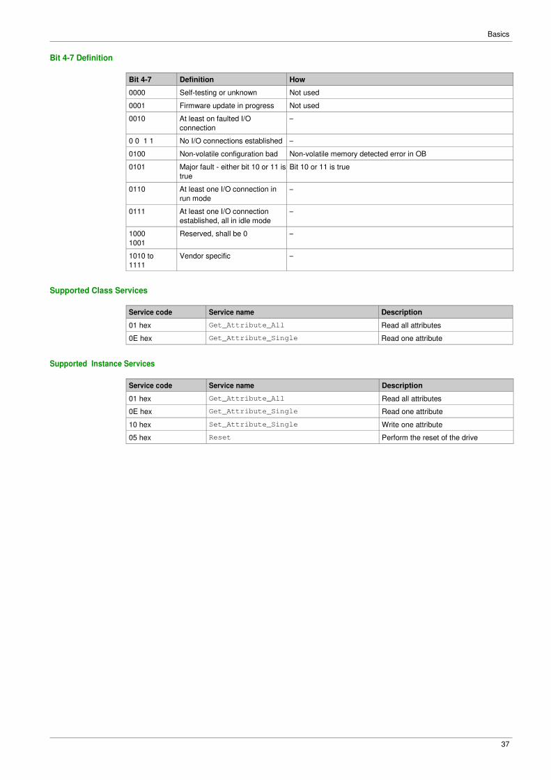
Bit 4-7 Definition
Bit 4-7 Definition How
0000 Self-testing or unknown Not used
0001 Firmware update in progress Not used
0010 At least on faulted I/O
connection
–
0 0 1 1 No I/O connections established –
0100 Non-volatile configuration bad Non-volatile memory detected error in OB
0101 Major fault - either bit 10 or 11 is
true
Bit 10 or 11 is true
0110 At least one I/O connection in
run mode
–
0111 At least one I/O connection
established, all in idle mode
–
1000
1001
Reserved, shall be 0 –
1010 to
1111
Vendor specific –
Supported Class Services
Service code Service name Description
01 hex Get_Attribute_All Read all attributes
0E hex Get_Attribute_Single Read one attribute
Supported Instance Services
Service code Service name Description
01 hex Get_Attribute_All Read all attributes
0E hex Get_Attribute_Single Read one attribute
10 hex Set_Attribute_Single Write one attribute
05 hex Reset Perform the reset of the drive
Basics
38
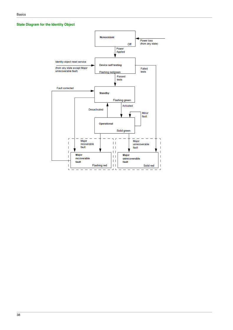
State Diagram for the Identity Object
Basics
39
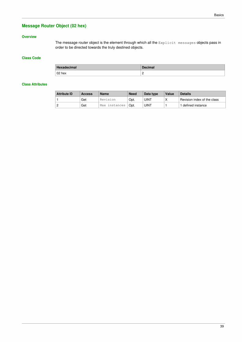
Message Router Object (02 hex)
Overview
The message router object is the element through which all the Explicit messages objects pass in
order to be directed towards the truly destined objects.
Class Code
Hexadecimal Decimal
02 hex 2
Class Attributes
Attribute ID Access Name Need Data type Value Details
1 Get Revision Opt. UINT X Revision index of the class
2 Get Max instances Opt. UINT 1 1 defined instance
Basics
40
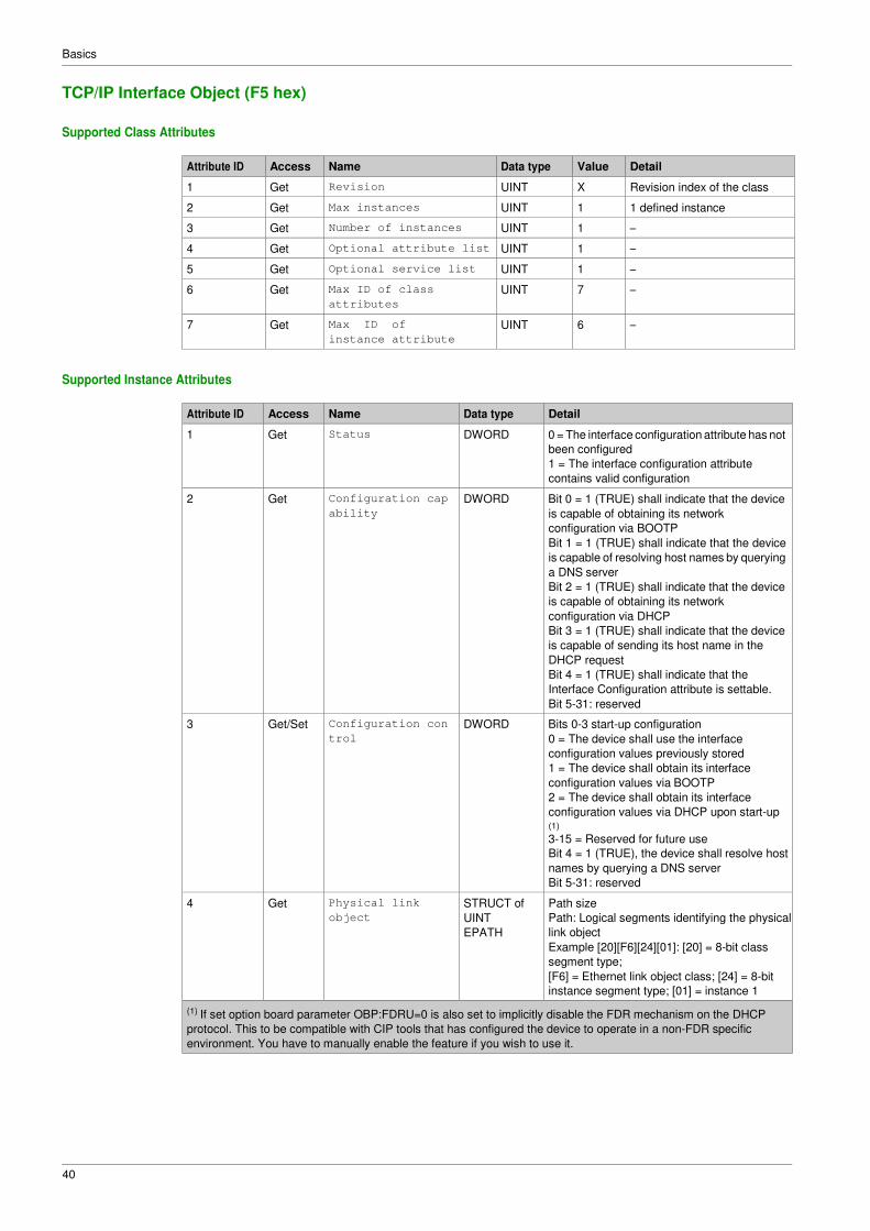
TCP/IP Interface Object (F5 hex)
Supported Class Attributes
Attribute ID Access Name Data type Value Detail
1 Get Revision UINT X Revision index of the class
2 Get Max instances UINT 1 1 defined instance
3 Get Number of instances UINT 1 –
4 Get Optional attribute list UINT 1 –
5 Get Optional service list UINT 1 –
6 Get Max ID of class
attributes
UINT 7 –
7 Get Max ID of
instance attribute
UINT 6 –
Supported Instance Attributes
Attribute ID Access Name Data type Detail
1 Get Status DWORD 0 = The interface configuration attribute has not
been configured
1 = The interface configuration attribute
contains valid configuration
2 Get Configuration cap
ability
DWORD Bit 0 = 1 (TRUE) shall indicate that the device
is capable of obtaining its network
configuration via BOOTP
Bit 1 = 1 (TRUE) shall indicate that the device
is capable of resolving host names by querying
a DNS server
Bit 2 = 1 (TRUE) shall indicate that the device
is capable of obtaining its network
configuration via DHCP
Bit 3 = 1 (TRUE) shall indicate that the device
is capable of sending its host name in the
DHCP request
Bit 4 = 1 (TRUE) shall indicate that the
Interface Configuration attribute is settable.
Bit 5-31: reserved
3 Get/Set Configuration con
trol
DWORD Bits 0-3 start-up configuration
0 = The device shall use the interface
configuration values previously stored
1 = The device shall obtain its interface
configuration values via BOOTP
2 = The device shall obtain its interface
configuration values via DHCP upon start-up (1)
3-15 = Reserved for future use
Bit 4 = 1 (TRUE), the device shall resolve host
names by querying a DNS server
Bit 5-31: reserved
4 Get Physical link
object
STRUCT of
UINT
EPATH
Path size
Path: Logical segments identifying the physical
link object
Example [20][F6][24][01]: [20] = 8-bit class
segment type;
[F6] = Ethernet link object class; [24] = 8-bit
instance segment type; [01] = instance 1
(1) If set option board parameter OBP:FDRU=0 is also set to implicitly disable the FDR mechanism on the DHCP
protocol. This to be compatible with CIP tools that has configured the device to operate in a non-FDR specific
environment. You have to manually enable the feature if you wish to use it.
Basics
41
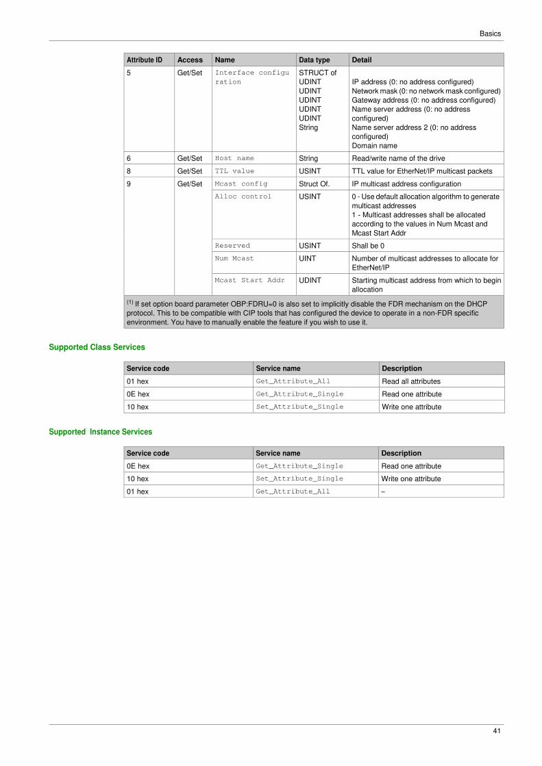
Attribute ID Access Name Data type Detail
5 Get/Set Interface configu
ration
STRUCT of
UDINT
UDINT
UDINT
UDINT
UDINT
String
IP address (0: no address configured)
Network mask (0: no network mask configured)
Gateway address (0: no address configured)
Name server address (0: no address
configured)
Name server address 2 (0: no address
configured)
Domain name
6 Get/Set Host name String Read/write name of the drive
8 Get/Set TTL value USINT TTL value for EtherNet/IP multicast packets
9 Get/Set Mcast config Struct Of. IP multicast address configuration
Alloc control USINT 0 - Use default allocation algorithm to generate
multicast addresses
1 - Multicast addresses shall be allocated
according to the values in Num Mcast and
Mcast Start Addr
Reserved USINT Shall be 0
Num Mcast UINT Number of multicast addresses to allocate for
EtherNet/IP
Mcast Start Addr UDINT Starting multicast address from which to begin
allocation
(1) If set option board parameter OBP:FDRU=0 is also set to implicitly disable the FDR mechanism on the DHCP
protocol. This to be compatible with CIP tools that has configured the device to operate in a non-FDR specific
environment. You have to manually enable the feature if you wish to use it.
Supported Class Services
Service code Service name Description
01 hex Get_Attribute_All Read all attributes
0E hex Get_Attribute_Single Read one attribute
10 hex Set_Attribute_Single Write one attribute
Supported Instance Services
Service code Service name Description
0E hex Get_Attribute_Single Read one attribute
10 hex Set_Attribute_Single Write one attribute
01 hex Get_Attribute_All –
Basics
42
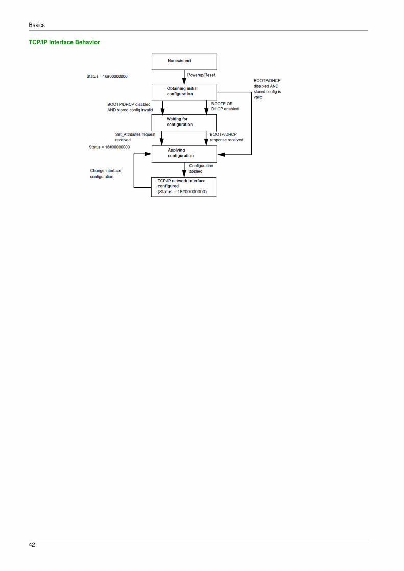
TCP/IP Interface Behavior
Basics
43
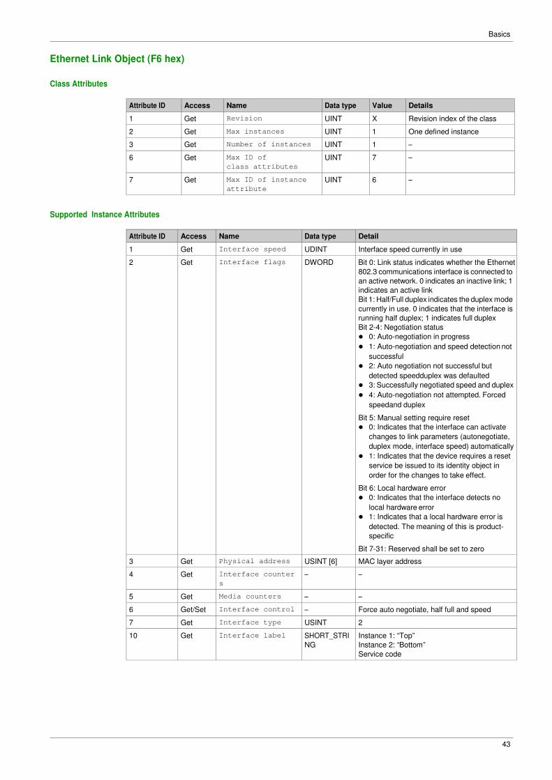
Ethernet Link Object (F6 hex)
Class Attributes
Attribute ID Access Name Data type Value Details
1 Get Revision UINT X Revision index of the class
2 Get Max instances UINT 1 One defined instance
3 Get Number of instances UINT 1 –
6 Get Max ID of
class attributes
UINT 7 –
7 Get Max ID of instance
attribute
UINT 6 –
Supported Instance Attributes
Attribute ID Access Name Data type Detail
1 Get Interface speed UDINT Interface speed currently in use
2 Get Interface flags DWORD Bit 0: Link status indicates whether the Ethernet
802.3 communications interface is connected to
an active network. 0 indicates an inactive link; 1
indicates an active link
Bit 1: Half/Full duplex indicates the duplex mode
currently in use. 0 indicates that the interface is
running half duplex; 1 indicates full duplex
Bit 2-4: Negotiation status
� 0: Auto-negotiation in progress
� 1: Auto-negotiation and speed detection not
successful
� 2: Auto negotiation not successful but
detected speedduplex was defaulted
� 3: Successfully negotiated speed and duplex
� 4: Auto-negotiation not attempted. Forced
speedand duplex
Bit 5: Manual setting require reset
� 0: Indicates that the interface can activate
changes to link parameters (autonegotiate,
duplex mode, interface speed) automatically
� 1: Indicates that the device requires a reset
service be issued to its identity object in
order for the changes to take effect.
Bit 6: Local hardware error
� 0: Indicates that the interface detects no
local hardware error
� 1: Indicates that a local hardware error is
detected. The meaning of this is product-
specific
Bit 7-31: Reserved shall be set to zero
3 Get Physical address USINT [6] MAC layer address
4 Get Interface counter
s
– –
5 Get Media counters – –
6 Get/Set Interface control – Force auto negotiate, half full and speed
7 Get Interface type USINT 2
10 Get Interface label SHORT_STRI
NG
Instance 1: “Top”
Instance 2: “Bottom”
Service code
Basics
44
Supported Class Services
Service code Service name Description
0E hex Get_Attribute_Single Read one attribute
01 hex Get_Attribute_All –
Supported Instance Services
Service code Service name Description
0E hex Get_Attribute_Single Read one attribute
10 hex Set_Attribute_Single Write one attribute
01 hex Get_Attribute_All –
4C hex Get_And_Clear Same than Get_Attribute_Single
Basics
45
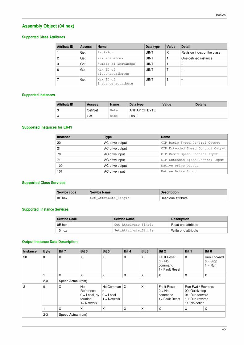
Assembly Object (04 hex)
Supported Class Attributes
Attribute ID Access Name Data type Value Detail
1 Get Revision UINT X Revision index of the class
2 Get Max instances UINT 1 One defined instance
3 Get Number of instances UINT 1 –
6 Get Max ID of
class attributes
UINT 7 –
7 Get Max ID of
instance attribute
UINT 3 –
Supported Instances
Attribute ID Access Name Data type Value Details
3 Get/Set Data ARRAY OF BYTE
4 Get Size UINT
Supported Instances for ER41
Instance Type Name
20 AC drive output CIP Basic Speed Control Output
21 AC drive output CIP Extended Speed Control Output
70 AC drive input CIP Basic Speed Control Input
71 AC drive input CIP Extended Speed Control Input
100 AC drive output Native Drive Output
101 AC drive input Native Drive Input
Supported Class Services
Service code Service Name Description
0E hex Get_Attribute_Single Read one attribute
Supported Instance Services
Service Code Service Name Description
0E hex Get_Attribute_Single Read one attribute
10 hex Set_Attribute_Single Write one attribute
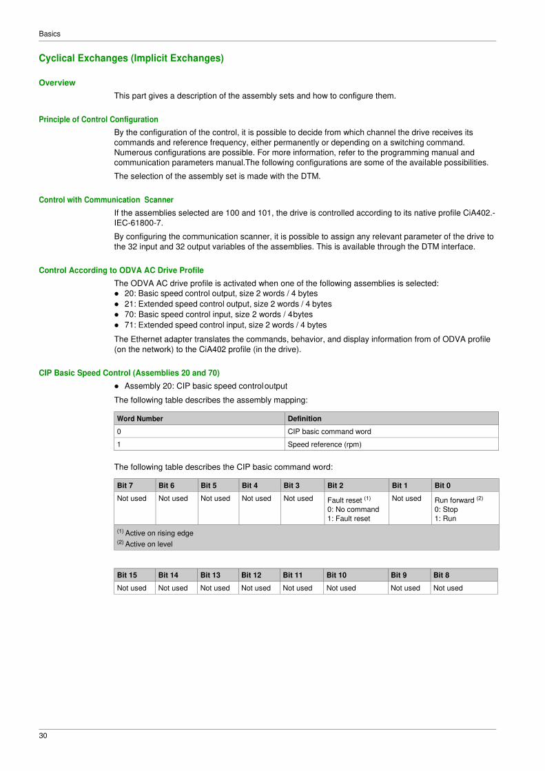
Output Instance Data Description
Instance Byte Bit 7 Bit 6 Bit 5 Bit 4 Bit 3 Bit 2 Bit 1 Bit 0
20 0 X X X X X Fault Reset
0 = No
command
1= Fault Reset
X Run Forward
0 = Stop
1 = Run
1 X X X X X X X X
2-3 Speed Actual (rpm)
21 0 X Net
Reference
0 = Local, by
terminal
1= Network
NetComman
d
0 = Local
1 = Network
X X Fault Reset
0 = No
command
1= Fault Reset
Run Fwd / Reverse:
00: Quick stop
01: Run forward
10: Run reverse
11: No action
1 X X X X X X X X
2-3 Speed Actual (rpm)
Basics
46
Instance Byte Bit 7 Bit 6 Bit 5 Bit 4 Bit 3 Bit 2 Bit 1 Bit 0
100 0-1 I/O Scanning word 1
2-3 I/O Scanning word 2
4-5 I/O Scanning word 3
6-7 I/O Scanning word 4
8-9 I/O Scanning word 5
10-11 I/O Scanning word 6
70 0 X X X X X 0 = Stopped
1 = Running
X 0 = No error
1 = Error
1 X X X X X X X X
2-3 Speed Actual (rpm)
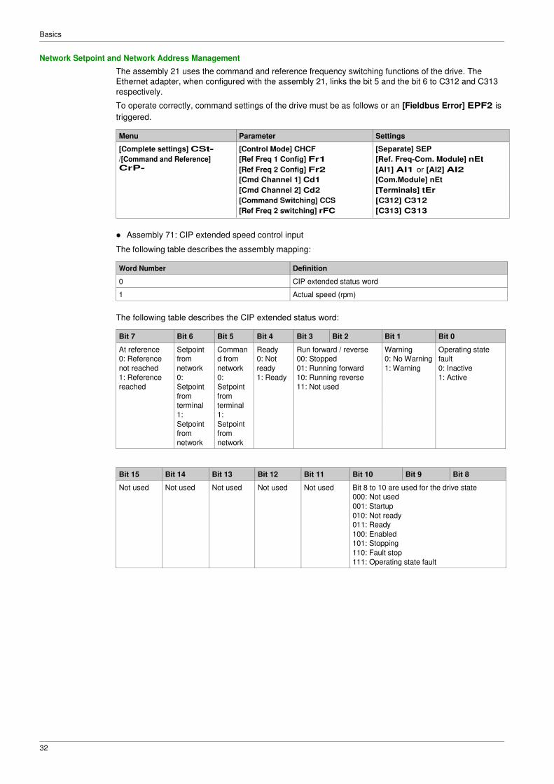
71 0 At reference
0 = Not
reached
1 = Reached
Ref From Net
0 = From
terminal
1 = From
network
Cmd From
Net
0 = From
terminal
1 = From
network
Ready
0 = Not
ready
1 =Ready
Running Fwd / reverse
00: Stopped
01: Running Forward
10: Running reverse
11: Not used
Warning
0 = No
warning
1 = Warning
Not used
1 X X X X X 000: Not used
001: Startup
010: Not ready
011: Ready
100: Enabled
101: Stopping
110: Fault stop
111: Operating state fault
2-3 Speed Actual (rpm)
101 0-1 Scanner Read word 1
2-3 Scanner Read word 2
4-5 Scanner Read word 3
6-7 Scanner Read word 4
8-9 Scanner Read word 5
10-11 Scanner Read word 6
Basics
47
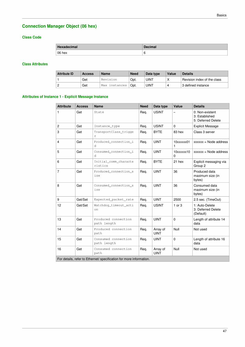
Connection Manager Object (06 hex)
Class Code
Hexadecimal Decimal
06 hex 6
Class Attributes
Attribute ID Access Name Need Data type Value Details
1 Get Revision Opt. UINT X Revision index of the class
2 Get Max instances Opt. UINT 4 3 defined instance
Attributes of Instance 1 - Explicit Message Instance
Attribute Access Name Need Data type Value Details
1 Get State Req. USINT – 0: Non-existent
3: Established
5: Deferred Delete
2 Get Instance_type Req. USINT 0 Explicit Message
3 Get TransportClass_trigge
r
Req. BYTE 83 hex Class 3 server
4 Get Produced_connection_i
d
Req. UINT 10xxxxxx01
1
xxxxxx = Node address
5 Get Consumed_connection_i
d
Req. UINT 10xxxxxx10
0
xxxxxx = Node address
6 Get Initial_comm_characte
ristics
Req. BYTE 21 hex Explicit messaging via
Group 2
7 Get Produced_connection_s
ize
Req. UINT 36 Produced data
maximum size (in
bytes)
8 Get Consumed_connection_s
ize
Req. UINT 36 Consumed data
maximum size (in
bytes)
9 Get/Set Expected_packet_rate Req. UINT 2500 2.5 sec. (TimeOut)
12 Get/Set Watchdog_timeout_acti
on
Req. USINT 1 or 3 1: Auto-Delete
3: Deferred Delete
(Default)
13 Get Produced connection
path length
Req. UINT 0 Length of attribute 14
data
14 Get Produced connection
path
Req. Array of
UINT
Null Not used
15 Get Consumed connection
path length
Req. UINT 0 Length of attribute 16
data
16 Get Consumed connection
path
Req. Array of
UINT
Null Not used
For details, refer to Ethernet/ specification for more information.
Basics
48
Supported Class Attributes
Attribute ID Access Name Data type Value Details
1 Get Revision UINT X Revision index of the class
2 Get Max Instances UINT 1 1 defined instance
3 Get Number of Instances UINT 1 –
4 Get Optional attribute
list
STRUCT
of
– List of optional attribute numbers
6 Get Max ID of class
attributes
UINT 7 –
7 Get Max ID of
instance attributes
UINT – Attribute ID number of last class
attribute
Supported Instance1 (Explicit) Attributes
Attribute ID Access Name Data type Details
1 Get Open Requests UINT Number of forward open service requests
received.
2 Get Open Format Rejec
ts
UINT Number of forward open service requests which
were rejected due to bad format.
3 Get Open Resources Re
jects
UINT Number of forward open service requests which
were rejected due to lack of resources.
4 Get Open Other Reject
s
UINT Number of forward open service requests which
were rejected for reasons other than bad format or
lack of resources.
5 Get Close Requests UINT Number of forward close service requests
received.
6 Get Close Format Requ
ests
UINT Number of forward close service requests which
were rejected due to bad format.
7 Get Close Other Reque
sts
UINT Number of forward close service requests which
were rejected for reasons other than bad format.
8 Get Connection Timeou
ts
UINT Total number of connection timeouts that have
occurred in connections controlled by this
connection manager.
Supported Class Services
Service code Service name Description
01 hex Get_Attribute_All Read all attributes
0E hex Get_Attribute_Single Read one attribute
Supported Instance Services
Service code Service name Description
0E hex Get_Attribute_Single Read one attribute
10 hex Set_Attribute_Single Write one attribute
4E hex Forward_Close Closes a connection
54 hex Forward_Open Opens a connection, maximum data
size is 511 bytes
Basics
49
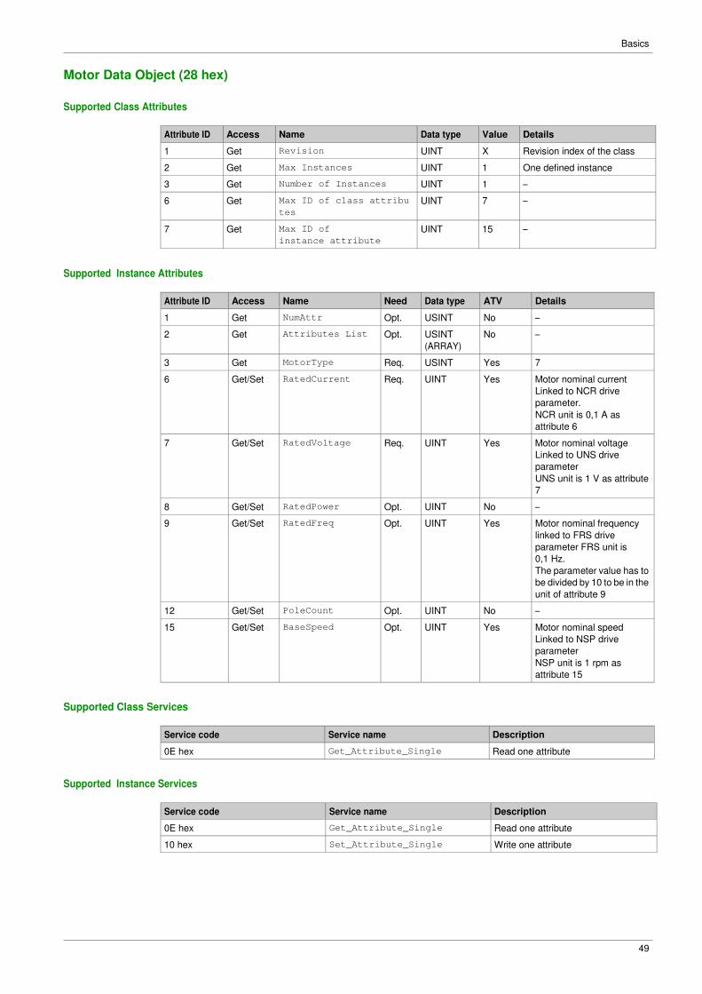
Motor Data Object (28 hex)
Supported Class Attributes
Attribute ID Access Name Data type Value Details
1 Get Revision UINT X Revision index of the class
2 Get Max Instances UINT 1 One defined instance
3 Get Number of Instances UINT 1 –
6 Get Max ID of class attribu
tes
UINT 7 –
7 Get Max ID of
instance attribute
UINT 15 –
Supported Instance Attributes
Attribute ID Access Name Need Data type ATV Details
1 Get NumAttr Opt. USINT No –
2 Get Attributes List Opt. USINT
(ARRAY)
No –
3 Get MotorType Req. USINT Yes 7
6 Get/Set RatedCurrent Req. UINT Yes Motor nominal current
Linked to NCR drive
parameter.
NCR unit is 0,1 A as
attribute 6
7 Get/Set RatedVoltage Req. UINT Yes Motor nominal voltage
Linked to UNS drive
parameter
UNS unit is 1 V as attribute
7
8 Get/Set RatedPower Opt. UINT No –
9 Get/Set RatedFreq Opt. UINT Yes Motor nominal frequency
linked to FRS drive
parameter FRS unit is
0,1 Hz.
The parameter value has to
be divided by 10 to be in the
unit of attribute 9
12 Get/Set PoleCount Opt. UINT No –
15 Get/Set BaseSpeed Opt. UINT Yes Motor nominal speed
Linked to NSP drive
parameter
NSP unit is 1 rpm as
attribute 15
Supported Class Services
Service code Service name Description
0E hex Get_Attribute_Single Read one attribute
Supported Instance Services
Service code Service name Description
0E hex Get_Attribute_Single Read one attribute
10 hex Set_Attribute_Single Write one attribute
Basics
50
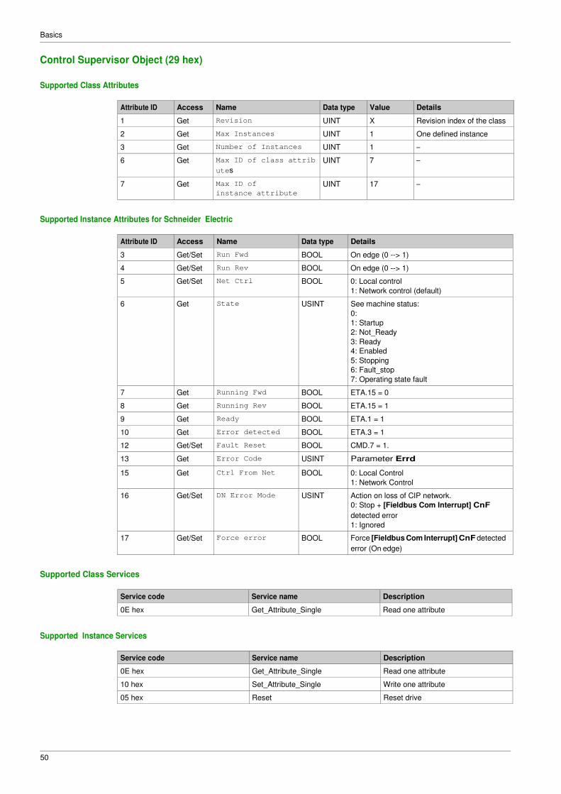
Control Supervisor Object (29 hex)
Supported Class Attributes
Attribute ID Access Name Data type Value Details
1 Get Revision UINT X Revision index of the class
2 Get Max Instances UINT 1 One defined instance
3 Get Number of Instances UINT 1 –
6 Get Max ID of class attrib
utes
UINT 7 –
7 Get Max ID of
instance attribute
UINT 17 –
Supported Instance Attributes for Schneider Electric
Attribute ID Access Name Data type Details
3 Get/Set Run Fwd BOOL On edge (0 --> 1)
4 Get/Set Run Rev BOOL On edge (0 --> 1)
5 Get/Set Net Ctrl BOOL 0: Local control
1: Network control (default)
6 Get State USINT See machine status:
0:
1: Startup
2: Not_Ready
3: Ready
4: Enabled
5: Stopping
6: Fault_stop
7: Operating state fault
7 Get Running Fwd BOOL ETA.15 = 0
8 Get Running Rev BOOL ETA.15 = 1
9 Get Ready BOOL ETA.1 = 1
10 Get Error detected BOOL ETA.3 = 1
12 Get/Set Fault Reset BOOL CMD.7 = 1.
13 Get Error Code USINT Parameter Errd
15 Get Ctrl From Net BOOL 0: Local Control
1: Network Control
16 Get/Set DN Error Mode USINT Action on loss of CIP network.
0: Stop + [Fieldbus Com Interrupt] CnF
detected error
1: Ignored
17 Get/Set Force error BOOL Force [Fieldbus Com Interrupt] CnF detected
error (On edge)
Supported Class Services
Service code Service name Description
0E hex Get_Attribute_Single Read one attribute
Supported Instance Services
Service code Service name Description
0E hex Get_Attribute_Single Read one attribute
10 hex Set_Attribute_Single Write one attribute
05 hex Reset Reset drive
Basics
51
Control Supervisor States
Basics
52
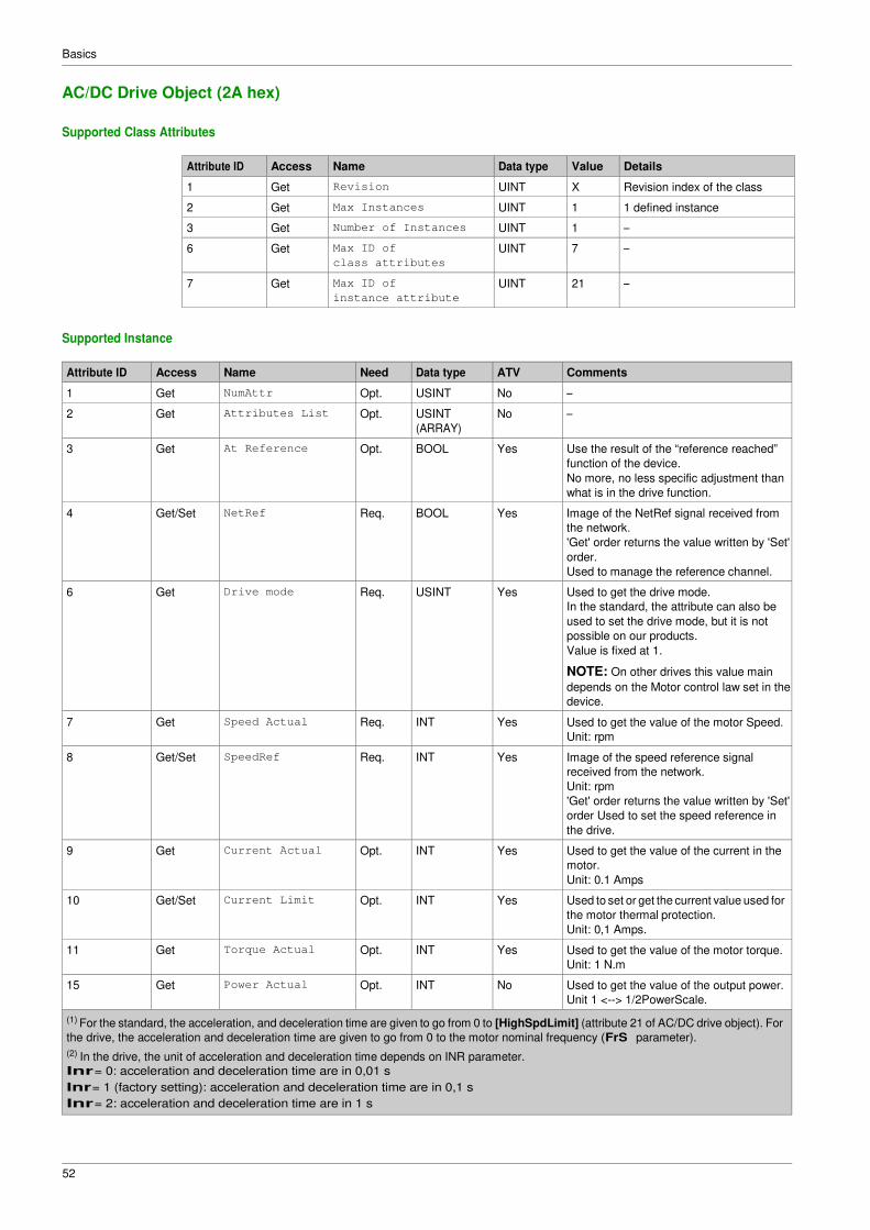
AC/DC Drive Object (2A hex)
Supported Class Attributes
Attribute ID Access Name Data type Value Details
1 Get Revision UINT X Revision index of the class
2 Get Max Instances UINT 1 1 defined instance
3 Get Number of Instances UINT 1 –
6 Get Max ID of
class attributes
UINT 7 –
7 Get Max ID of
instance attribute
UINT 21 –
Supported Instance
Attribute ID Access Name Need Data type ATV Comments
1 Get NumAttr Opt. USINT No –
2 Get Attributes List Opt. USINT
(ARRAY)
No –
3 Get At Reference Opt. BOOL Yes Use the result of the “reference reached”
function of the device.
No more, no less specific adjustment than
what is in the drive function.
4 Get/Set NetRef Req. BOOL Yes Image of the NetRef signal received from
the network.
'Get' order returns the value written by 'Set'
order.
Used to manage the reference channel.
6 Get Drive mode Req. USINT Yes Used to get the drive mode.
In the standard, the attribute can also be
used to set the drive mode, but it is not
possible on our products.
Value is fixed at 1.
NOTE: On other drives this value main
depends on the Motor control law set in the
device.
7 Get Speed Actual Req. INT Yes Used to get the value of the motor Speed.
Unit: rpm
8 Get/Set SpeedRef Req. INT Yes Image of the speed reference signal
received from the network.
Unit: rpm
'Get' order returns the value written by 'Set'
order Used to set the speed reference in
the drive.
9 Get Current Actual Opt. INT Yes Used to get the value of the current in the
motor.
Unit: 0.1 Amps
10 Get/Set Current Limit Opt. INT Yes Used to set or get the current value used for
the motor thermal protection.
Unit: 0,1 Amps.
11 Get Torque Actual Opt. INT Yes Used to get the value of the motor torque.
Unit: 1 N.m
15 Get Power Actual Opt. INT No Used to get the value of the output power.
Unit 1 <--> 1/2PowerScale.
(1) For the standard, the acceleration, and deceleration time are given to go from 0 to [HighSpdLimit] (attribute 21 of AC/DC drive object). For
the drive, the acceleration and deceleration time are given to go from 0 to the motor nominal frequency (FrS parameter).
(2) In the drive, the unit of acceleration and deceleration time depends on INR parameter.
Inr = 0: acceleration and deceleration time are in 0,01 s
Inr = 1 (factory setting): acceleration and deceleration time are in 0,1 s
Inr = 2: acceleration and deceleration time are in 1 s
Basics
53
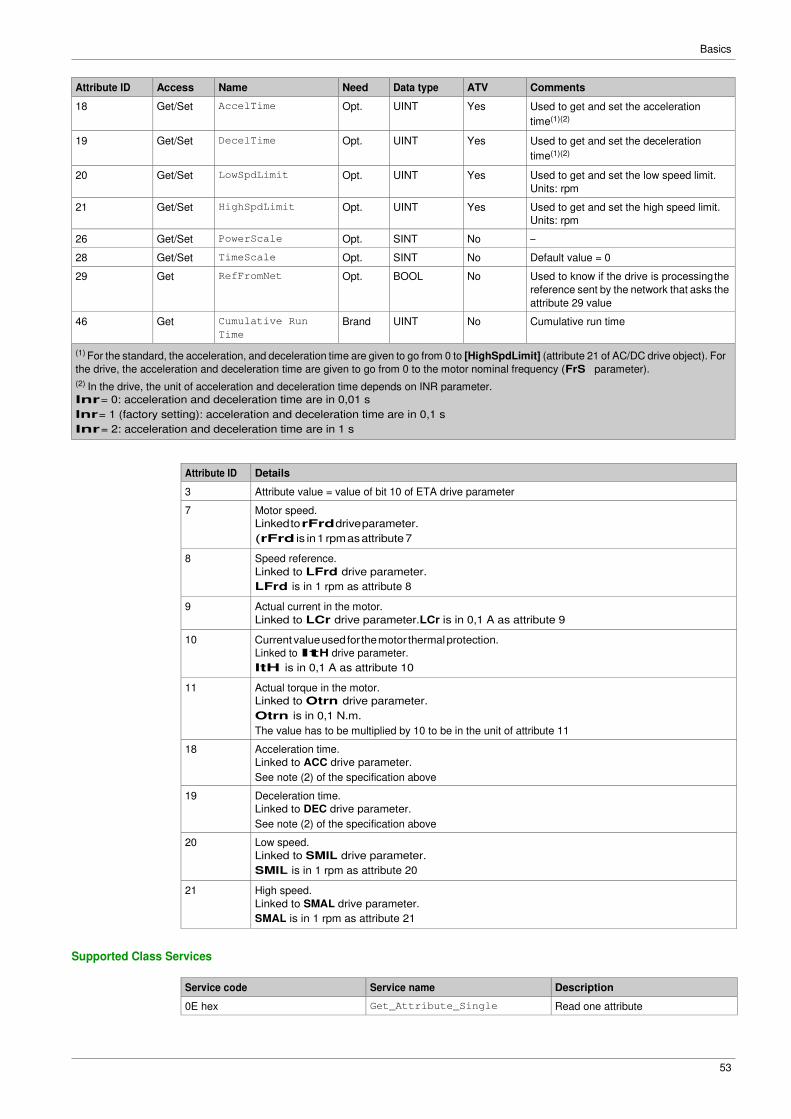
Attribute ID Access Name Need Data type ATV Comments
18 Get/Set AccelTime Opt. UINT Yes Used to get and set the acceleration
time(1)(2)
19 Get/Set DecelTime Opt. UINT Yes Used to get and set the deceleration
time(1)(2)
20 Get/Set LowSpdLimit Opt. UINT Yes Used to get and set the low speed limit.
Units: rpm
21 Get/Set HighSpdLimit Opt. UINT Yes Used to get and set the high speed limit.
Units: rpm
26 Get/Set PowerScale Opt. SINT No –
28 Get/Set TimeScale Opt. SINT No Default value = 0
29 Get RefFromNet Opt. BOOL No Used to know if the drive is processing the
reference sent by the network that asks the
attribute 29 value
46 Get Cumulative Run
Time
Brand UINT No Cumulative run time
(1) For the standard, the acceleration, and deceleration time are given to go from 0 to [HighSpdLimit] (attribute 21 of AC/DC drive object). For
the drive, the acceleration and deceleration time are given to go from 0 to the motor nominal frequency (FrS parameter).
(2) In the drive, the unit of acceleration and deceleration time depends on INR parameter.
Inr = 0: acceleration and deceleration time are in 0,01 s
Inr = 1 (factory setting): acceleration and deceleration time are in 0,1 s
Inr = 2: acceleration and deceleration time are in 1 s
Attribute ID Details
3 Attribute value = value of bit 10 of ETA drive parameter
7 Motor speed.
Linked to rFrd drive parameter.
(rFrd is in 1 rpm as attribute 7
8 Speed reference.
Linked to LFrd drive parameter.
LFrd is in 1 rpm as attribute 8
9 Actual current in the motor.
Linked to LCr drive parameter.LCr is in 0,1 A as attribute 9
10 Current value used for the motor thermal protection.
Linked to ItH drive parameter.
ItH is in 0,1 A as attribute 10
11 Actual torque in the motor.
Linked to Otrn drive parameter.
Otrn is in 0,1 N.m.
The value has to be multiplied by 10 to be in the unit of attribute 11
18 Acceleration time.
Linked to ACC drive parameter.
See note (2) of the specification above
19 Deceleration time.
Linked to DEC drive parameter.
See note (2) of the specification above
20 Low speed.
Linked to SMIL drive parameter.
SMIL is in 1 rpm as attribute 20
21 High speed.
Linked to SMAL drive parameter.
SMAL is in 1 rpm as attribute 21
Supported Class Services
Service code Service name Description
0E hex Get_Attribute_Single Read one attribute
Basics
54
Supported Instance Services
Service code Service name Description
0E hex Get_Attribute_Single Read one attribute
10 hex Set_Attribute_Single Write one attribute
Basics
55
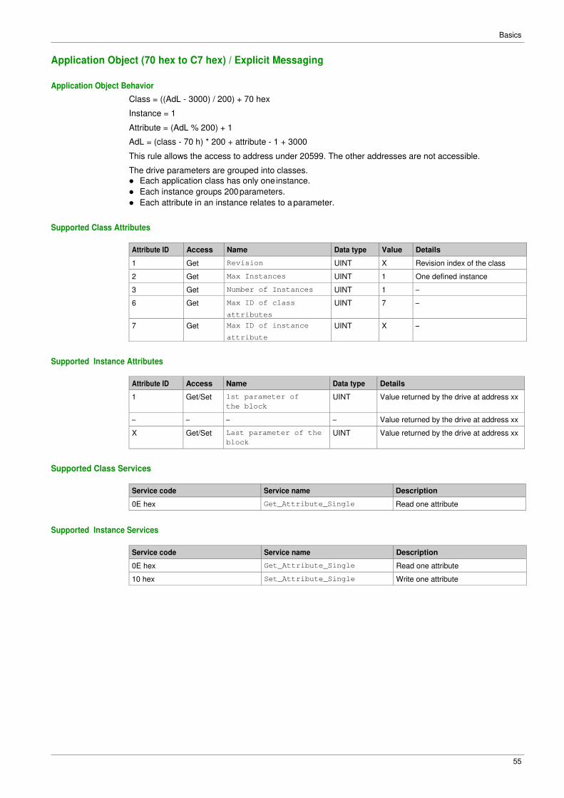
Application Object (70 hex to C7 hex) / Explicit Messaging
Application Object Behavior
Class = ((AdL - 3000) / 200) + 70 hex
Instance = 1
Attribute = (AdL % 200) + 1
AdL = (class - 70 h) * 200 + attribute - 1 + 3000
This rule allows the access to address under 20599. The other addresses are not accessible.
The drive parameters are grouped into classes.
� Each application class has only one instance.
� Each instance groups 200 parameters.
� Each attribute in an instance relates to a parameter.
Supported Class Attributes
Attribute ID Access Name Data type Value Details
1 Get Revision UINT X Revision index of the class
2 Get Max Instances UINT 1 One defined instance
3 Get Number of Instances UINT 1 –
6 Get Max ID of class
attributes
UINT 7 –
7 Get Max ID of instance
attribute
UINT X –
Supported Instance Attributes
Attribute ID Access Name Data type Details
1 Get/Set 1st parameter of
the block
UINT Value returned by the drive at address xx
– – – – Value returned by the drive at address xx
X Get/Set Last parameter of the
block
UINT Value returned by the drive at address xx
Supported Class Services
Service code Service name Description
0E hex Get_Attribute_Single Read one attribute
Supported Instance Services
Service code Service name Description
0E hex Get_Attribute_Single Read one attribute
10 hex Set_Attribute_Single Write one attribute
Basics
56
Base Energy Object (4E hex)
Overview
The base energy object acts as an Energy Supervisor for CIP Energy implementations. It is responsible
for providing a time base for energy values, provides energy mode services, and can provide aggregation
services for aggregating energy values up through the various levels of an industrial facility. It also provides
a standard format for reporting energy metering results.
Class Code
Hexadecimal Decimal
4E hex 78
Class Attributes
Attribute ID Access Name Data type Value Details
1 Get Revision UINT X Revision index of the class
2 Get Max instances UINT 1 1 defined instance
3 Get Number of instances UINT 1 –
Instance Attributes
Attribute ID Access Name Data type Value Details
1 Get Energy/Resource
Type
UINT 1 1 = Electrical
2 Get Base Energy
Object
Capabilities
UINT – See definition in the following table
3 Get Energy Accuracy UINT – See definition in the following table
4 Get Energy Accuracy
Basis
UINT – See definition in the following table
7 Get Consumed Energy
Odometer
ODOMETE
R
– The consumed energy value in kWh
8 Get Generated Energy
Odometer
ODOMETE
R
– The generated energy value in kWh
9 Get Net Energy Odometer SIGNED_O
DOMETER
– The generated energy value in kWh
The following table provides the Odometer and Signed_Odometer structure principle:
Data Type Structure Description of Data Type
Element
Semantics of Value
ODOMETER STRUCT of: SIGNED_ODOMETER
STRUCT of:
– –
UINT INT x10n ±Unit1 x 10n
UINT INT x10n+3 ±Unit1 x 10n+3
UINT INT x10n+6 ±Unit1 x 10n+6
UINT INT x10n+9 ±Unit1 x 10n+9
UINT INT x10n+12 ±Unit1 x 10n+12
The valid range of n shall be a SINT between 0 and -15.
The following table provides the Odometer type in Kilowatt-hours units and n = -3:
x10n+12 x10n+9 x10n+6 x10n+3 x10n
Terawatt-hours
(kWh x 109)
Gigawatt-hours
(kWh x 106)
Megawatt-hours
(kWh x 103)
Kilowatt-hours (kWh) Watt-hours
(kWh x 10-3)
Basics
57
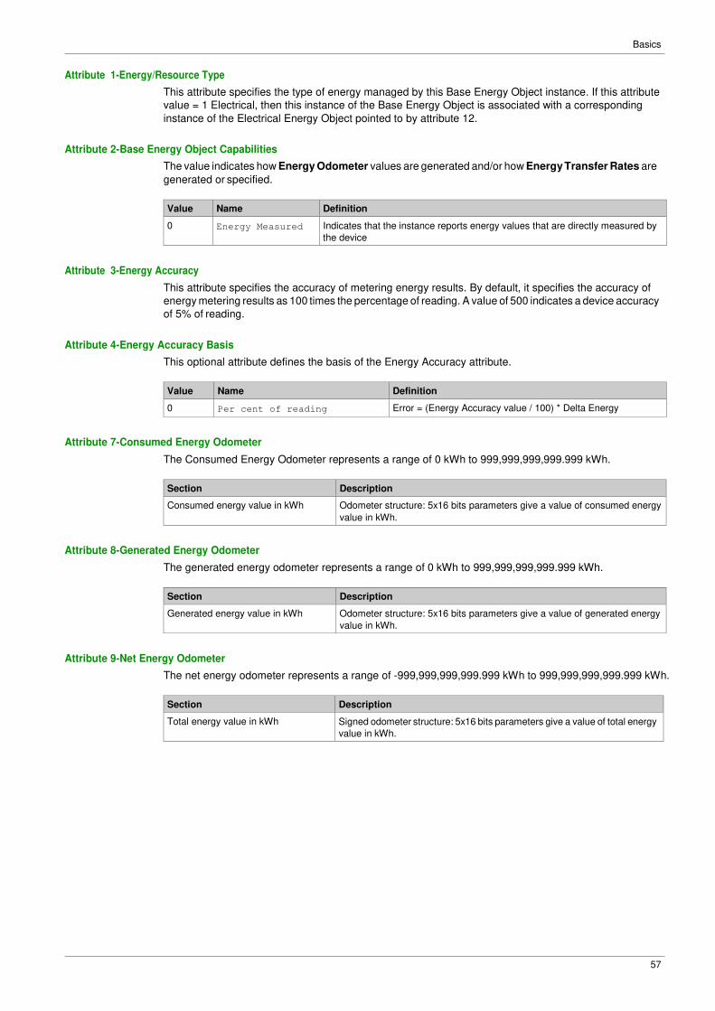
Attribute 1-Energy/Resource Type
This attribute specifies the type of energy managed by this Base Energy Object instance. If this attribute
value = 1 Electrical, then this instance of the Base Energy Object is associated with a corresponding
instance of the Electrical Energy Object pointed to by attribute 12.
Attribute 2-Base Energy Object Capabilities
The value indicates how Energy Odometer values are generated and/or how Energy Transfer Rates are
generated or specified.
Value Name Definition
0 Energy Measured Indicates that the instance reports energy values that are directly measured by
the device
Attribute 3-Energy Accuracy
This attribute specifies the accuracy of metering energy results. By default, it specifies the accuracy of
energy metering results as 100 times the percentage of reading. A value of 500 indicates a device accuracy
of 5% of reading.
Attribute 4-Energy Accuracy Basis
This optional attribute defines the basis of the Energy Accuracy attribute.
Value Name Definition
0 Per cent of reading Error = (Energy Accuracy value / 100) * Delta Energy
Attribute 7-Consumed Energy Odometer
The Consumed Energy Odometer represents a range of 0 kWh to 999,999,999,999.999 kWh.
Section Description
Consumed energy value in kWh Odometer structure: 5x16 bits parameters give a value of consumed energy
value in kWh.
Attribute 8-Generated Energy Odometer
The generated energy odometer represents a range of 0 kWh to 999,999,999,999.999 kWh.
Section Description
Generated energy value in kWh Odometer structure: 5x16 bits parameters give a value of generated energy
value in kWh.
Attribute 9-Net Energy Odometer
The net energy odometer represents a range of -999,999,999,999.999 kWh to 999,999,999,999.999 kWh.
Section Description
Total energy value in kWh Signed odometer structure: 5x16 bits parameters give a value of total energy
value in kWh.
Basics
58
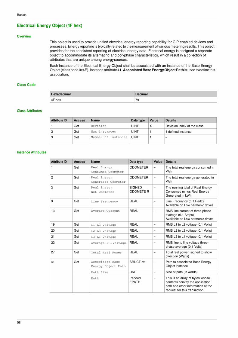
Electrical Energy Object (4F hex)
Overview
This object is used to provide unified electrical energy reporting capability for CIP enabled devices and
processes. Energy reporting is typically related to the measurement of various metering results. This object
provides for the consistent reporting of electrical energy data. Electrical energy is assigned a separate
object to accommodate its alternating and polyphase characteristics, which result in a collection of
attributes that are unique among energy sources.
Each instance of the Electrical Energy Object shall be associated with an instance of the Base Energy Object (class code 0x4E). Instance attribute 41, Associated Base Energy Object Path is used to define this
association.
Class Code
Hexadecimal Decimal
4F hex 79
Class Attributes
Attribute ID Access Name Data type Value Details
1 Get Revision UINT X Revision index of the class
2 Get Max instances UINT 1 1 defined instance
3 Get Number of instances UINT 1 –
Instance Attributes
Attribute ID Access Name Data type Value Details
1 Get Real Energy
Consumed Odometer
ODOMETER – The total real energy consumed in
kWh
2 Get Real Energy
Generated Odometer
ODOMETER – The total real energy generated in
kWh
3 Get Real Energy
Net Odometer
SIGNED_
ODOMETE R
– The running total of Real Energy
Consumed minus Real Energy
Generated in kWh
9 Get Line Frequency REAL – Line Frequency (0.1 Hertz)
Available on Low harmonic drives
13 Get Average Current REAL – RMS line current of three-phase
average (0.1 Amps)
Available on Low harmonic drives
19 Get L1-L2 Voltage REAL – RMS L1 to L2 voltage (0.1 Volts)
20 Get L2-L3 Voltage REAL – RMS L2 to L3 voltage (0.1 Volts)
21 Get L3-L1 Voltage REAL – RMS L3 to L1 voltage (0.1 Volts)
22 Get Average L-L Voltage REAL – RMS line to line voltage three-
phase average (0.1 Volts)
27 Get Total Real Power REAL – Total real power, signed to show
direction (Watts)
41 Get Associated Base
Energy Object Path
SRUCT of: – Path to associated Base Energy
Object instance
Path Size UNIT – Size of path (in words)
Path Padded
EPATH
– This is an array of bytes whose
contents convey the application
path and other information of the
request for this transaction
Basics
59
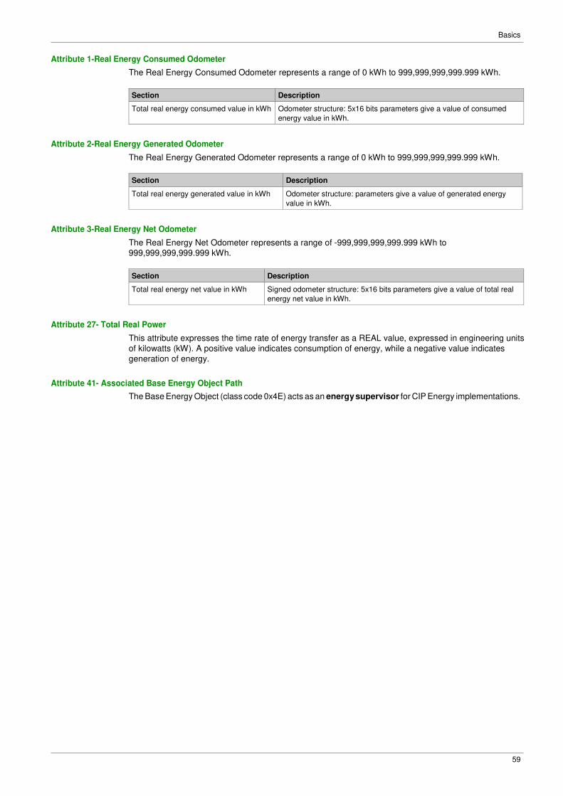
Attribute 1-Real Energy Consumed Odometer
The Real Energy Consumed Odometer represents a range of 0 kWh to 999,999,999,999.999 kWh.
Section Description
Total real energy consumed value in kWh Odometer structure: 5x16 bits parameters give a value of consumed
energy value in kWh.
Attribute 2-Real Energy Generated Odometer
The Real Energy Generated Odometer represents a range of 0 kWh to 999,999,999,999.999 kWh.
Section Description
Total real energy generated value in kWh Odometer structure: parameters give a value of generated energy
value in kWh.
Attribute 3-Real Energy Net Odometer
The Real Energy Net Odometer represents a range of -999,999,999,999.999 kWh to
999,999,999,999.999 kWh.
Section Description
Total real energy net value in kWh Signed odometer structure: 5x16 bits parameters give a value of total real
energy net value in kWh.
Attribute 27- Total Real Power
This attribute expresses the time rate of energy transfer as a REAL value, expressed in engineering units
of kilowatts (kW). A positive value indicates consumption of energy, while a negative value indicates
generation of energy.
Attribute 41- Associated Base Energy Object Path
The Base Energy Object (class code 0x4E) acts as an energy supervisor for CIP Energy implementations.
Basics
60
61
Chapter 3 Hardware Setup
What Is in This Chapter?
This chapter contains the following topics:
Topic Page
Hardware Presentation 62
Firmware Version 62
Installation of the Module 63
Electrical Installation 64
Cable Routing Practice 65
62
Hardware Setup
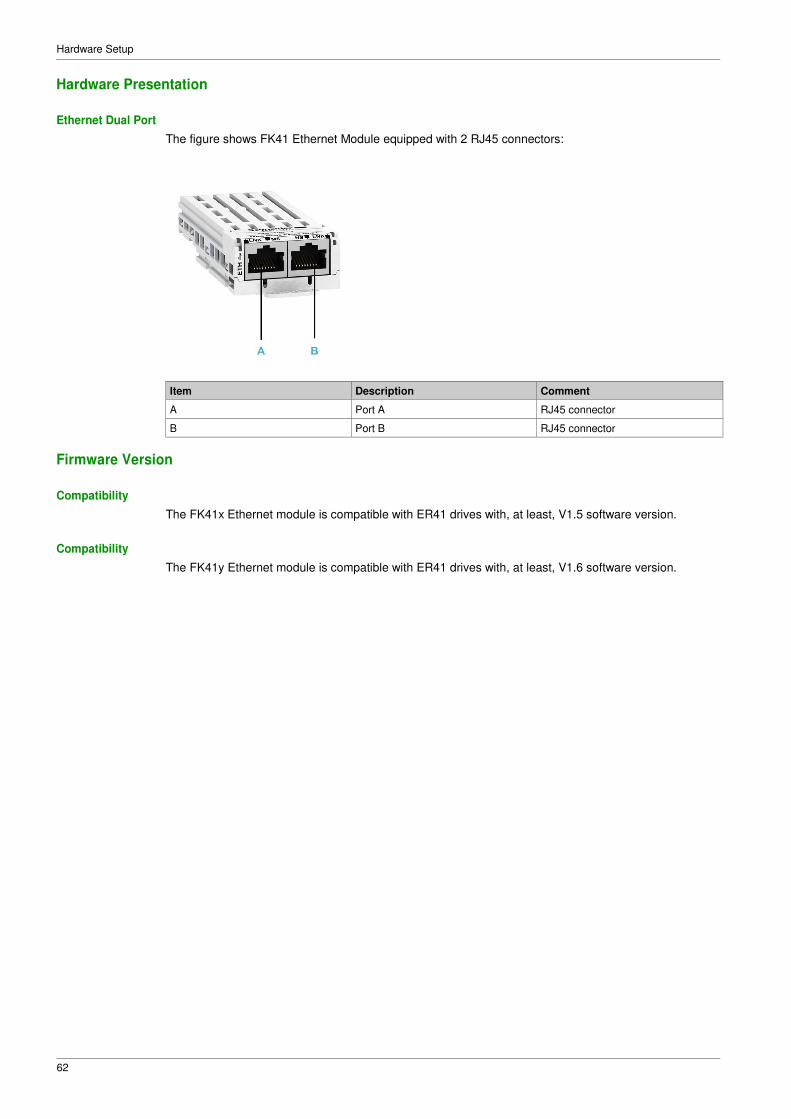
Hardware Presentation
Ethernet Dual Port
The figure shows FK41 Ethernet Module equipped with 2 RJ45 connectors:
Item Description Comment
A Port A RJ45 connector
B Port B RJ45 connector
Firmware Version
Compatibility
The FK41x Ethernet module is compatible with ER41 drives with, at least, V1.5 software version.
Compatibility
The FK41y Ethernet module is compatible with ER41 drives with, at least, V1.6 software version.
63
Hardware Setup
Installation of the Module
Before Starting
Check that the module catalog number marked on the label is the same as that on the delivery note
corresponding to the purchase order.
Remove the fieldbus module from its packaging and check that it has not been damaged in transit.
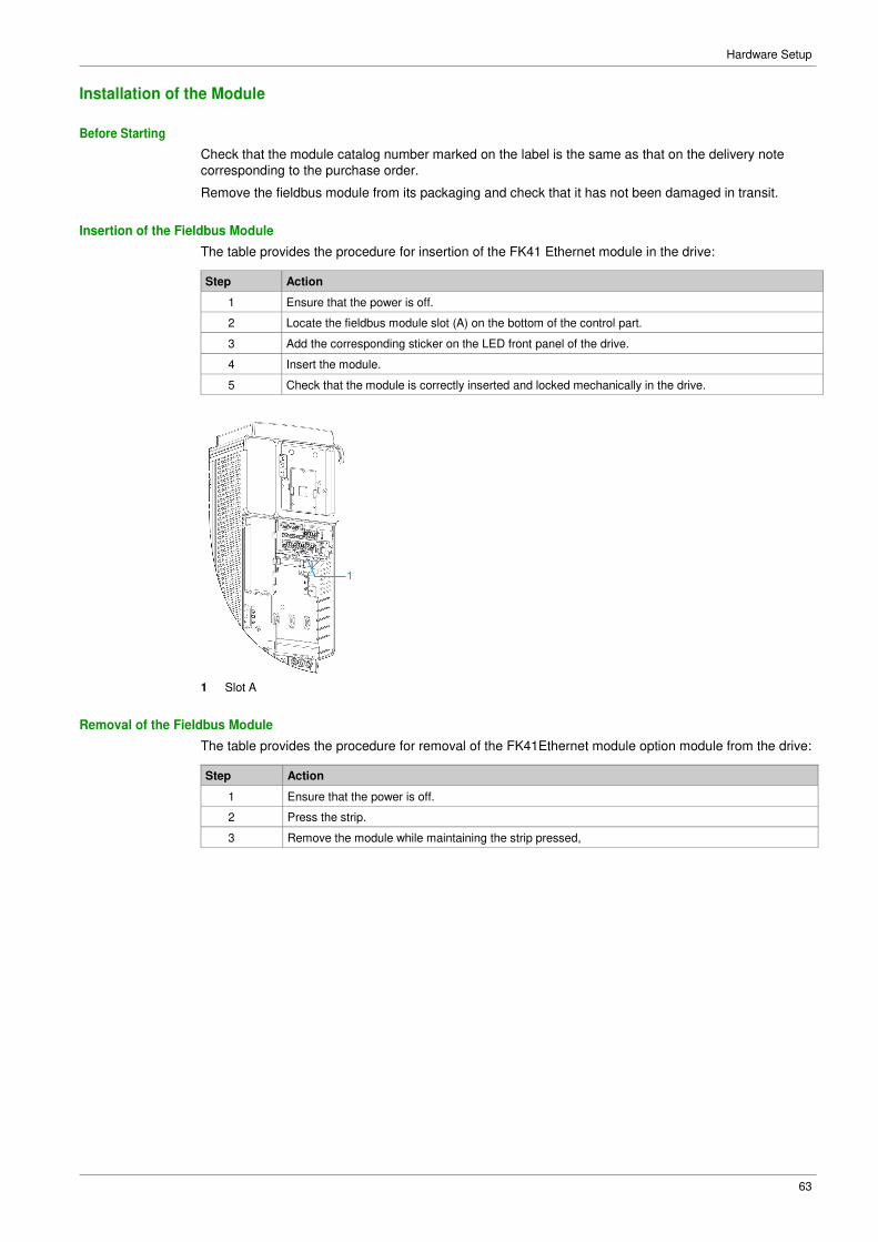
Insertion of the Fieldbus Module
The table provides the procedure for insertion of the FK41 Ethernet module in the drive:
Step Action
1 Ensure that the power is off.
2 Locate the fieldbus module slot (A) on the bottom of the control part.
3 Add the corresponding sticker on the LED front panel of the drive.
4 Insert the module.
5 Check that the module is correctly inserted and locked mechanically in the drive.
1 Slot A
Removal of the Fieldbus Module
The table provides the procedure for removal of the FK41Ethernet module option module from the drive:
Step Action
1 Ensure that the power is off.
2 Press the strip.
3 Remove the module while maintaining the strip pressed,
64
Hardware Setup
Electrical Installation
Pin Layout
The FK41 Ethernet module is equipped with 2 RJ45 female sockets for the Ethernet connection.
The table provides the pin out details of each RJ45 connector:
Pin Signal Meaning
1 Tx+ Ethernet transmit line +
2 Tx- Ethernet transmit line –
3 Rx+ Ethernet receive line +
4 − −
5 − −
6 Rx- Ethernet receive line –
7 − −
8 − −
Cable Specification
Cable specifications are as follows:
� Minimum Cat 5e,
� Use equipotential bonding conductors (100 BASE-TX, category 5e or industrial Ethernet fast connect)
� Connector RJ45, no crossover cable
� Shield: both ends grounded
� Twisted-pair cable
� Verify that wiring, cables, and connected interfaces meet the PELV requirements.
� Maximum cable length per segment = 100 m (328 ft) / 6 plugs
NOTE: RSTP function is not compatible with half duplex configuration. All devices involved in the RSTP
topology shall be RSTP capable and configured.
65
Hardware Setup
Cable Routing Practice
Installation Topology
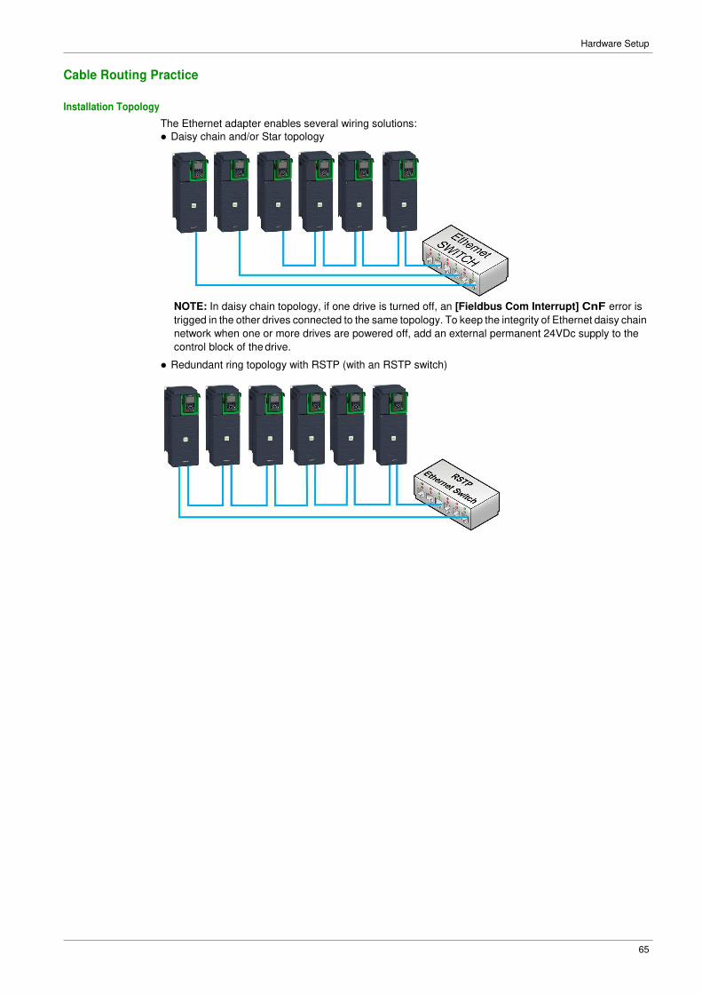
The Ethernet adapter enables several wiring solutions:
� Daisy chain and/or Star topology
NOTE: In daisy chain topology, if one drive is turned off, an [Fieldbus Com Interrupt] CnF error is
trigged in the other drives connected to the same topology. To keep the integrity of Ethernet daisy chain
network when one or more drives are powered off, add an external permanent 24VDc supply to the
control block of the drive.
� Redundant ring topology with RSTP (with an RSTP switch)
66
Hardware Setup
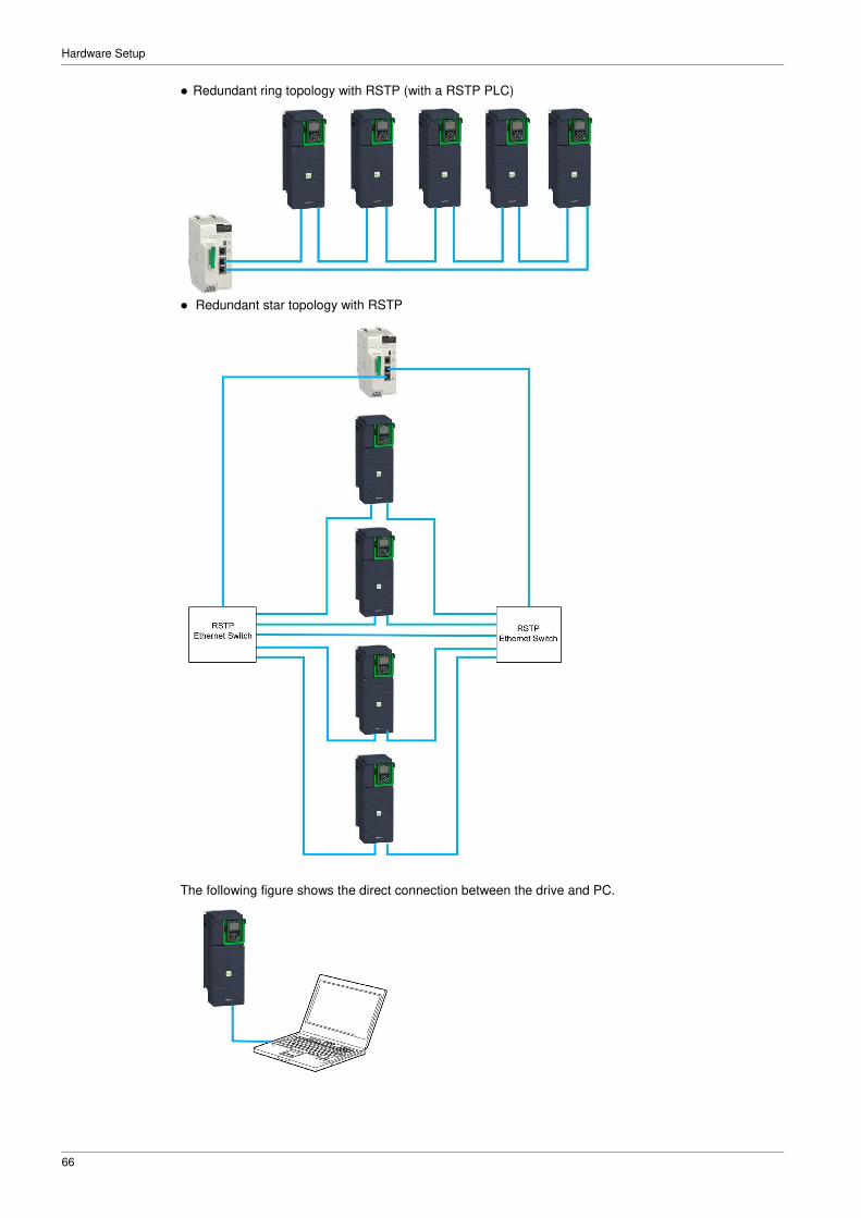
� Redundant ring topology with RSTP (with a RSTP PLC)
� Redundant star topology with RSTP
The following figure shows the direct connection between the drive and PC.
67
Chapter 4 Software Setup
What Is in This Chapter?
This chapter contains the following sections:
Section Topic Page
4.1 Basic Settings 68
4.2 Additional Settings 79
4.3 Fast Device Replacement 88
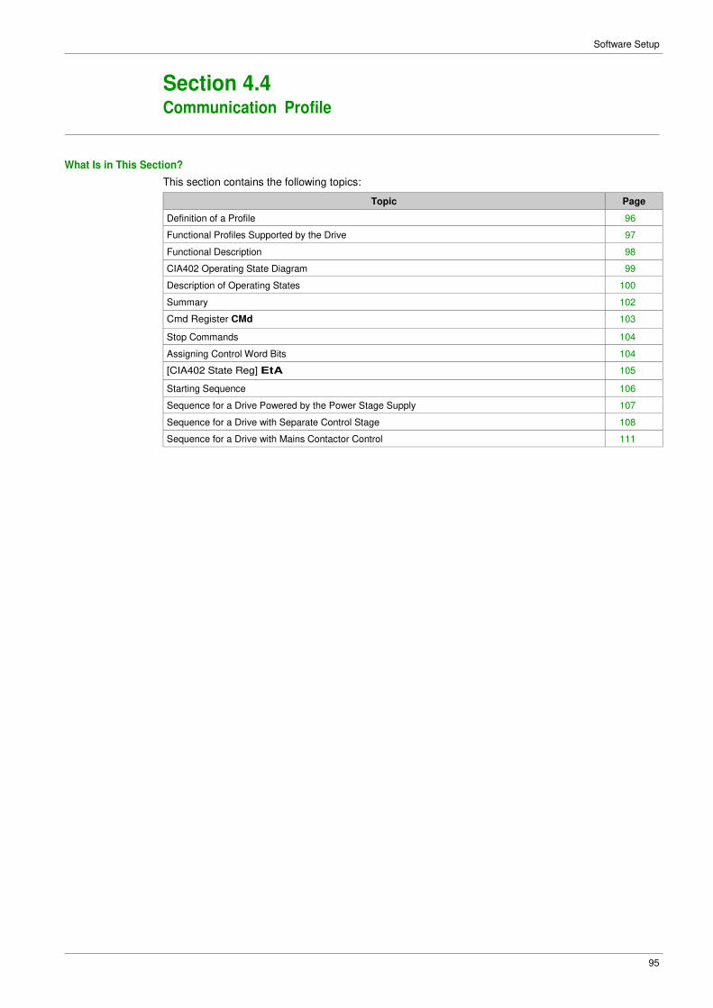
4.4 Communication Profile 95
4.5 Embedded Webserver 112
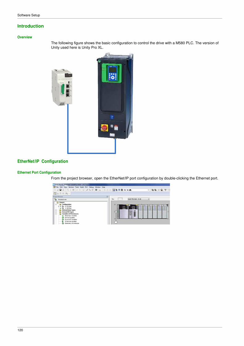
4.6 Fieldbus Integration Using Unity Pro (M580) 119
68
Software Setup
Section 4.1 Basic Settings
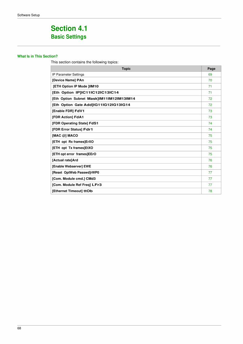
What Is in This Section?
This section contains the following topics:
Topic Page
IP Parameter Settings 69
[Device Name] PAn 70
[ETH Option IP Mode ]IM10 71
[Eth Option IP]IC11IC12IC13IC14 71
[Eth Option Subnet Mask]IM11IM12IM13IM14 72
[Eth Option Gate Add]IG11IG12IG13IG14 72
[Enable FDR] FdV1 73
[FDR Action] FdA1 73
[FDR Operating State] FdS1 74
[FDR Error Status] Fdr1 74
[MAC @] MACO 75
[ETH opt Rx frames]ErXO 75
[ETH opt Tx frames]EtXO 75
[ETH opt error frames]EErO 75
[Actual rate]Ard 76
[Enable Webserver] EWE 76
[Reset OptWeb Passwd]rWP0 77
[Com. Module cmd.] CMd3 77
[Com. Module Ref Freq] LFr3 77
[Ethernet Timeout] ttOb 78
69
Software Setup
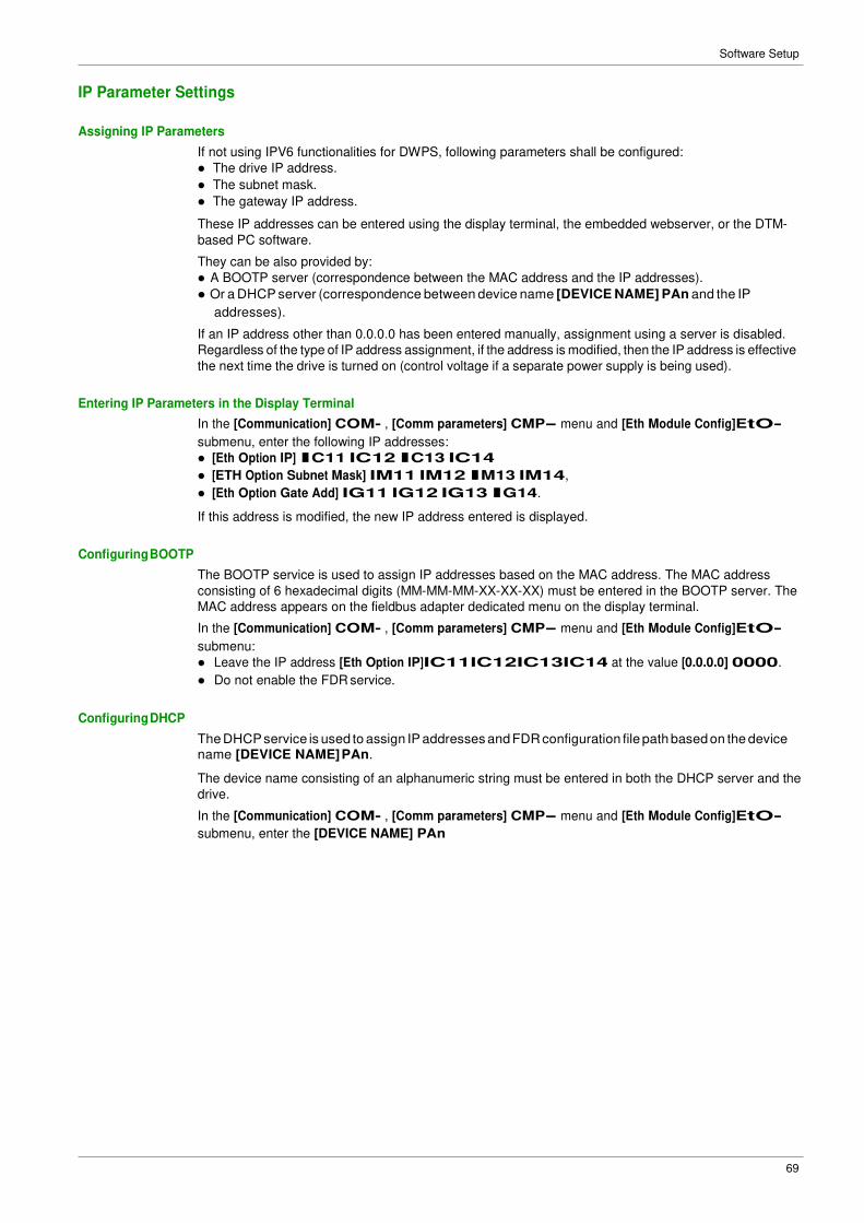
IP Parameter Settings
Assigning IP Parameters
If not using IPV6 functionalities for DWPS, following parameters shall be configured:
� The drive IP address.
� The subnet mask.
� The gateway IP address.
These IP addresses can be entered using the display terminal, the embedded webserver, or the DTM-
based PC software.
They can be also provided by:
� A BOOTP server (correspondence between the MAC address and the IP addresses).
� Or a DHCP server (correspondence between device name [DEVICE NAME] PAn and the IP
addresses).
If an IP address other than 0.0.0.0 has been entered manually, assignment using a server is disabled.
Regardless of the type of IP address assignment, if the address is modified, then the IP address is effective
the next time the drive is turned on (control voltage if a separate power supply is being used).
Entering IP Parameters in the Display Terminal
In the [Communication] COM- , [Comm parameters] CMP- menu and [Eth Module Config]EtO-
submenu, enter the following IP addresses:
� [Eth Option IP] IC11 IC12 IC13 IC14
� [ETH Option Subnet Mask] IM11 IM12 IM13 IM14,
� [Eth Option Gate Add] IG11 IG12 IG13 IG14.
If this address is modified, the new IP address entered is displayed.
Configuring BOOTP
The BOOTP service is used to assign IP addresses based on the MAC address. The MAC address
consisting of 6 hexadecimal digits (MM-MM-MM-XX-XX-XX) must be entered in the BOOTP server. The
MAC address appears on the fieldbus adapter dedicated menu on the display terminal.
In the [Communication] COM- , [Comm parameters] CMP- menu and [Eth Module Config]EtO-
submenu:
� Leave the IP address [Eth Option IP]IC11IC12IC13IC14 at the value [0.0.0.0] 0000.
� Do not enable the FDR service.
Configuring DHCP
The DHCP service is used to assign IP addresses and FDR configuration file path based on the device name [DEVICE NAME] PAn.
The device name consisting of an alphanumeric string must be entered in both the DHCP server and the
drive.
In the [Communication] COM- , [Comm parameters] CMP- menu and [Eth Module Config]EtO-
submenu, enter the [DEVICE NAME] PAn
70
Software Setup
[Device Name] PAn
About This Parameter
This parameter is used set the device name.
Access
This parameter is accessible via [Communication] COM- , [Comm parameters] CMP- menu and [Eth
Module Config] EtO- submenu.
This is a read/write parameter
Possible Settings
The FDR (Fast Device Replacement) service is based on identification of the device by a Device Name. In
the case of the ER41 drive, this is represented by the [Device Name] PAn parameter. Verify that all the
network devices have different Device Name.
NOTE: The [Device Name] PAN is common for both Ethernet interfaces.
71
Software Setup
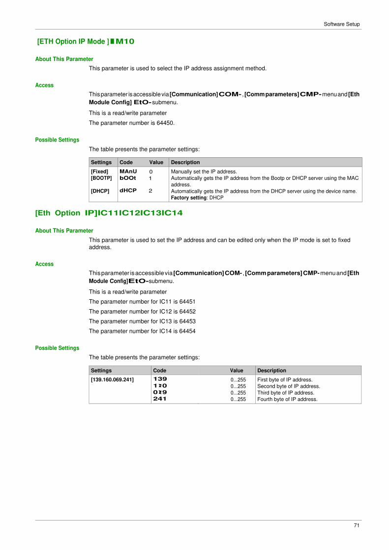
[ETH Option IP Mode ]IM10
About This Parameter
This parameter is used to select the IP address assignment method.
Access
This parameter is accessible via [Communication] COM- , [Comm parameters] CMP- menu and [Eth
Module Config] EtO- submenu.
This is a read/write parameter
The parameter number is 64450.
Possible Settings
The table presents the parameter settings:
Settings Code Value Description
[Fixed]
[BOOTP]
[DHCP]
MAnU 0
bOOt 1
dHCP 2
Manually set the IP address.
Automatically gets the IP address from the Bootp or DHCP server using the MAC
address.
Automatically gets the IP address from the DHCP server using the device name.
Factory setting: DHCP
[Eth Option IP]IC11IC12IC13IC14
About This Parameter
This parameter is used to set the IP address and can be edited only when the IP mode is set to fixed
address.
Access
This parameter is accessible via [Communication] COM- , [Comm parameters] CMP- menu and [Eth
Module Config]EtO-submenu.
This is a read/write parameter
The parameter number for IC11 is 64451
The parameter number for IC12 is 64452
The parameter number for IC13 is 64453
The parameter number for IC14 is 64454
Possible Settings
The table presents the parameter settings:
Settings Code Value Description
[139.160.069.241] 139 0...255 First byte of IP address.
1 0 0...255 Second byte of IP address.
0 9 0...255 Third byte of IP address.
241 0...255 Fourth byte of IP address.
72
Software Setup
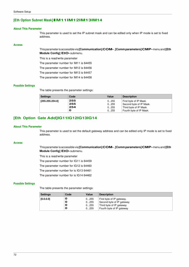
[Eth Option Subnet Mask]IM11IM12IM13IM14
About This Parameter
This parameter is used to set the IP subnet mask and can be edited only when IP mode is set to fixed
address.
Access
This parameter is accessible via [Communication] COM- , [Comm parameters] CMP- menu and [Eth
Module Config] EtO- submenu.
This is a read/write parameter
The parameter number for IM11 is 64455
The parameter number for IM12 is 64456
The parameter number for IM13 is 64457
The parameter number for IM14 is 64458
Possible Settings
The table presents the parameter settings:
Settings Code Value Description
[255.255.254.0] 255 0...255 First byte of IP Mask.
255 0...255 Second byte of IP Mask.
254 0...255 Third byte of IP Mask.
0 0...255 Fourth byte of IP Mask.
[Eth Option Gate Add]IG11IG12IG13IG14
About This Parameter
This parameter is used to set the default gateway address and can be edited only IP mode is set to fixed
address.
Access
This parameter is accessible via [Communication] COM- , [Comm parameters] CMP- menu and [Eth
Module Config] EtO- submenu.
This is a read/write parameter
The parameter number for IG11 is 64459
The parameter number for IG12 is 64460
The parameter number for is IG13 64461
The parameter number for is IG14 64462
Possible Settings
The table presents the parameter settings:
Settings Code Value Description
[0.0.0.0] 0 0...255 First byte of IP gateway.
0 0...255 Second byte of IP gateway
0 0...255 Third byte of IP gateway
0 0...255 Fourth byte of IP gateway
73
Software Setup
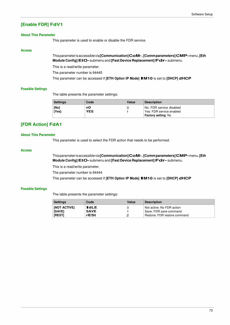
[Enable FDR] FdV1
About This Parameter
This parameter is used to enable or disable the FDR service.
Access
This parameter is accessible via [Communication] CoM-, [Comm parameters] CMP- menu, [Eth
Module Config] EtO- submenu and [Fast Device Replacement] Fdr- submenu.
This is a read/write parameter.
The parameter number is 64445
This parameter can be accessed if [ETH Option IP Mode] IM10 is set to [DHCP] dHCP
Possible Settings
The table presents the parameter settings:
Settings Code Value Description
[No]
[Yes]
nO 0
YES 1
No: FDR service disabled
Yes: FDR service enabled
Factory setting: No
[FDR Action] FdA1
About This Parameter
This parameter is used to select the FDR action that needs to be performed.
Access
This parameter is accessible via [Communication] CoM-, [Comm parameters] CMP- menu, [Eth
Module Config] EtO- submenu and [Fast Device Replacement] Fdr- submenu.
This is a read/write parameter.
The parameter number is 64444
This parameter can be accessed if [ETH Option IP Mode] IM10 is set to [DHCP] dHCP
Possible Settings
The table presents the parameter settings:
Settings Code Value Description
[NOT ACTIVE]
[SAVE]
[REST]
IdLE 0
SAVE 1
rESt 2
Not active: No FDR action
Save: FDR save command
Restore: FDR restore command
74
Software Setup
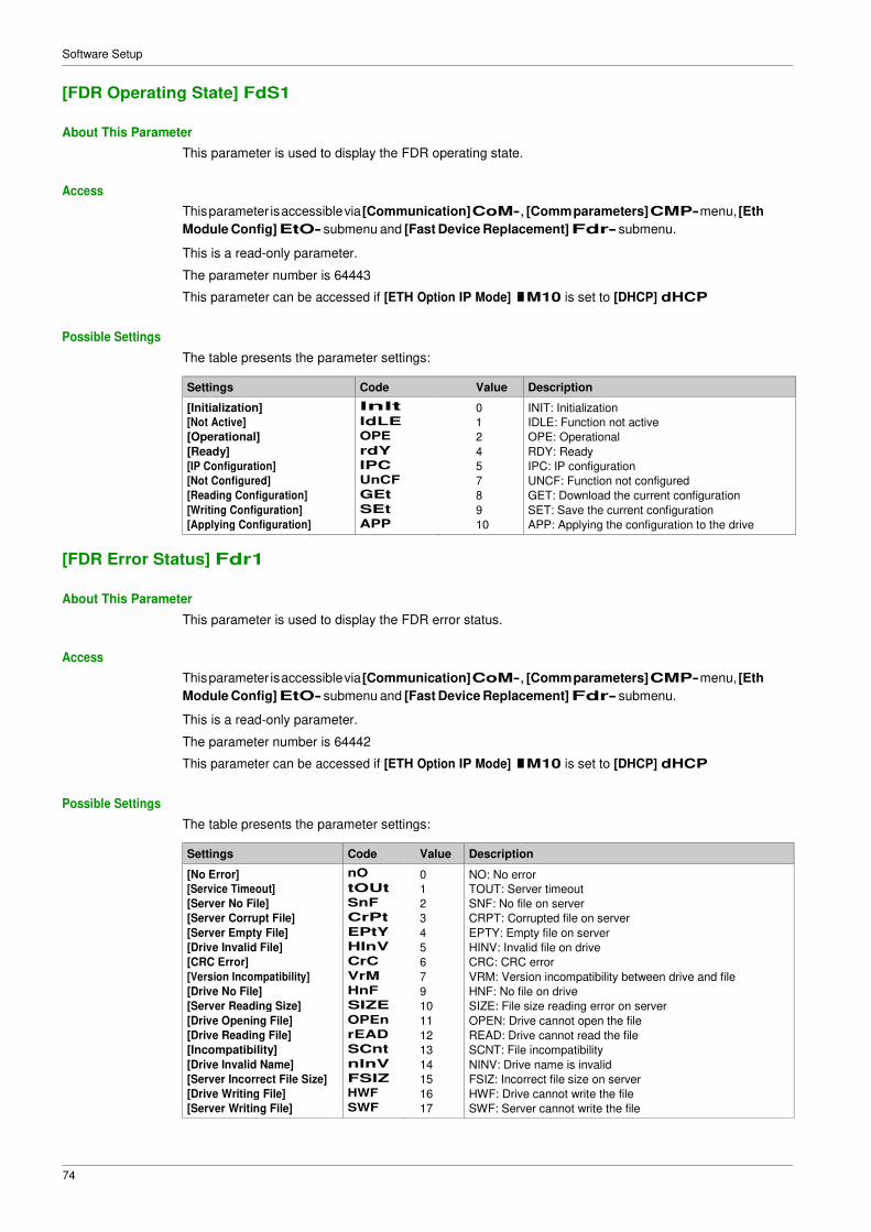
[FDR Operating State] FdS1
About This Parameter
This parameter is used to display the FDR operating state.
Access
This parameter is accessible via [Communication] CoM-, [Comm parameters] CMP- menu, [Eth
Module Config] EtO- submenu and [Fast Device Replacement] Fdr- submenu.
This is a read-only parameter.
The parameter number is 64443
This parameter can be accessed if [ETH Option IP Mode] IM10 is set to [DHCP] dHCP
Possible Settings
The table presents the parameter settings:
Settings Code Value Description
[Initialization] InIt 0 INIT: Initialization
[Not Active] IdLE 1 IDLE: Function not active
[Operational] OPE 2 OPE: Operational
[Ready] rdY 4 RDY: Ready
[IP Configuration] IPC 5 IPC: IP configuration
[Not Configured] UnCF 7 UNCF: Function not configured
[Reading Configuration] GEt 8 GET: Download the current configuration
[Writing Configuration] SEt 9 SET: Save the current configuration
[Applying Configuration] APP 10 APP: Applying the configuration to the drive
[FDR Error Status] Fdr1
About This Parameter
This parameter is used to display the FDR error status.
Access
This parameter is accessible via [Communication] CoM-, [Comm parameters] CMP- menu, [Eth
Module Config] EtO- submenu and [Fast Device Replacement] Fdr- submenu.
This is a read-only parameter.
The parameter number is 64442
This parameter can be accessed if [ETH Option IP Mode] IM10 is set to [DHCP] dHCP
Possible Settings
The table presents the parameter settings:
Settings Code Value Description
[No Error] nO 0 NO: No error
[Service Timeout] tOUt 1 TOUT: Server timeout
[Server No File] SnF 2 SNF: No file on server
[Server Corrupt File] CrPt 3 CRPT: Corrupted file on server
[Server Empty File] EPtY 4 EPTY: Empty file on server
[Drive Invalid File] HInV 5 HINV: Invalid file on drive
[CRC Error] CrC 6 CRC: CRC error
[Version Incompatibility] VrM 7 VRM: Version incompatibility between drive and file
[Drive No File] HnF 9 HNF: No file on drive
[Server Reading Size] SIZE 10 SIZE: File size reading error on server
[Drive Opening File] OPEn 11 OPEN: Drive cannot open the file
[Server Writing File] SWF 17 SWF: Server cannot write the file
75
Software Setup
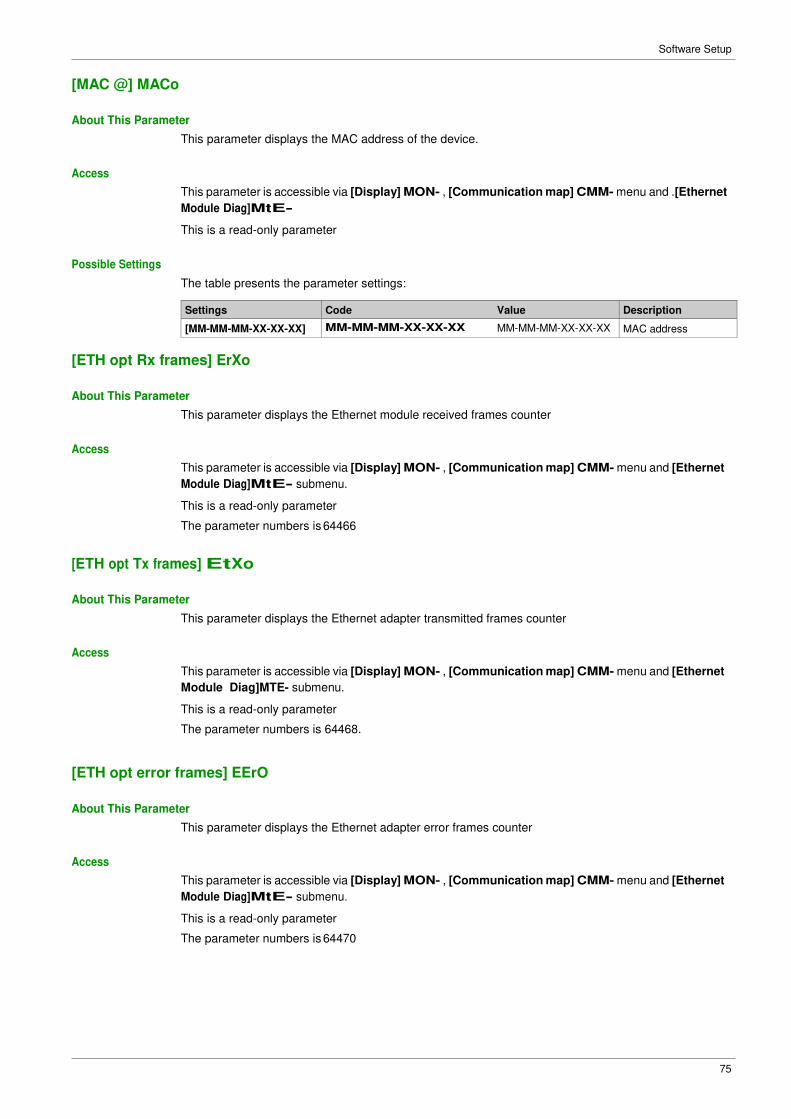
[MAC @] MACo
About This Parameter
This parameter displays the MAC address of the device.
Access
This parameter is accessible via [Display] MON- , [Communication map] CMM- menu and .[Ethernet
Module Diag]MtE-
This is a read-only parameter
Possible Settings
The table presents the parameter settings:
Settings Code Value Description
[MM-MM-MM-XX-XX-XX] MM-MM-MM-XX-XX-XX MM-MM-MM-XX-XX-XX MAC address
[ETH opt Rx frames] ErXo
About This Parameter
This parameter displays the Ethernet module received frames counter
Access
This parameter is accessible via [Display] MON- , [Communication map] CMM- menu and [Ethernet
Module Diag]MtE- submenu.
This is a read-only parameter
The parameter numbers is 64466
[ETH opt Tx frames] EtXo
About This Parameter
This parameter displays the Ethernet adapter transmitted frames counter
Access
This parameter is accessible via [Display] MON- , [Communication map] CMM- menu and [Ethernet
Module Diag]MTE- submenu.
This is a read-only parameter
The parameter numbers is 64468.
[ETH opt error frames] EErO
About This Parameter
This parameter displays the Ethernet adapter error frames counter
Access
This parameter is accessible via [Display] MON- , [Communication map] CMM- menu and [Ethernet
Module Diag]MtE- submenu.
This is a read-only parameter
The parameter numbers is 64470
76
Software Setup
[Actual rate] Ard
About This Parameter
This parameter displays the Ethernet adapter actual rate.
Access
This parameter is accessible via [Display] MON- , [Communication map] CMM- menu and [Ethernet
Module Diag] MtE- submenu.
This is a read-only parameter
The parameter numbers is 64413
Possible Settings
The table presents the parameter settings:
Settings Code Value Description
[Auto] AUtO Auto Data rate is auto detected depending on the first data packet received. [10M. full] 10F 10 F Data rate is set to10 Mbit/s full
[10M. half] 10H 10 H Data rate is set to10 Mbit/s half
[100M. full] 100F 100 F Data rate is set to100 Mbit/s full
[100M. half] 100H 100 H Data rate is set to100 Mbit/s half
Factory setting: Auto
[Enable Webserver] EWE
About This Parameter
This parameter is used to manage the fieldbus adapter Web services.
Access
This parameter is accessible via [My preferences] MYP- menu and [Webserver] WbS- submenu.
This is a read/write parameter
The parameter numbers is 64264.
Possible Settings
The table presents the parameter settings:
Settings Code Value Description
[No]
[Yes]
no 0
yes 1
Web services disabled
Web services enabled
Factory setting: Yes
77
Software Setup
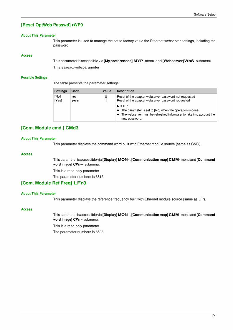
[Reset OptWeb Passwd] rWP0
About This Parameter
This parameter is used to manage the set to factory value the Ethernet webserver settings, including the
password.
Access
This parameter is accessible via [My preferences] MYP- menu and [Webserver] WbS- submenu.
This is a read/write parameter
Possible Settings
The table presents the parameter settings:
Settings Code Value Description
[No]
[Yes]
no 0
yes 1
Reset of the adapter webserver password not requested
Reset of the adapter webserver password requested
NOTE: � The parameter is set to [No] when the operation is done
� The webserver must be refreshed in browser to take into account the
new password.
[Com. Module cmd.] CMd3
About This Parameter
This parameter displays the command word built with Ethernet module source (same as CMD).
Access
This parameter is accessible via [Display] MON- , [Communication map] CMM- menu and [Command
word image] CW|- submenu.
This is a read-only parameter
The parameter numbers is 8513
[Com. Module Ref Freq] LFr3
About This Parameter
This parameter displays the reference frequency built with Ethernet module source (same as LFr).
Access
This parameter is accessible via [Display] MON- , [Communication map] CMM- menu and [Command
word image] CW| - submenu.
This is a read-only parameter
The parameter numbers is 8523
78
Software Setup
[Ethernet Timeout] ttOb
About This Parameter
This parameter is used to set the Ethernet timeout.
Access
This parameter is accessible via fieldbus using the Modbus address.
This is a read/write parameter
The parameter number is 64415.
Possible Settings
The table presents the parameter settings:
Settings Description
0.1...30 sec Factory setting: 10 sec
79
Software Setup
Section 4.2 Additional Settings
What Is in This Section?
This section contains the following topics:
Topic Page
FDR Settings 80
RSTP Settings 81
Configuring I/O Scanning 83
DNS Settings 84
SNTP Settings 85
SNMP Settings 86
80
Software Setup
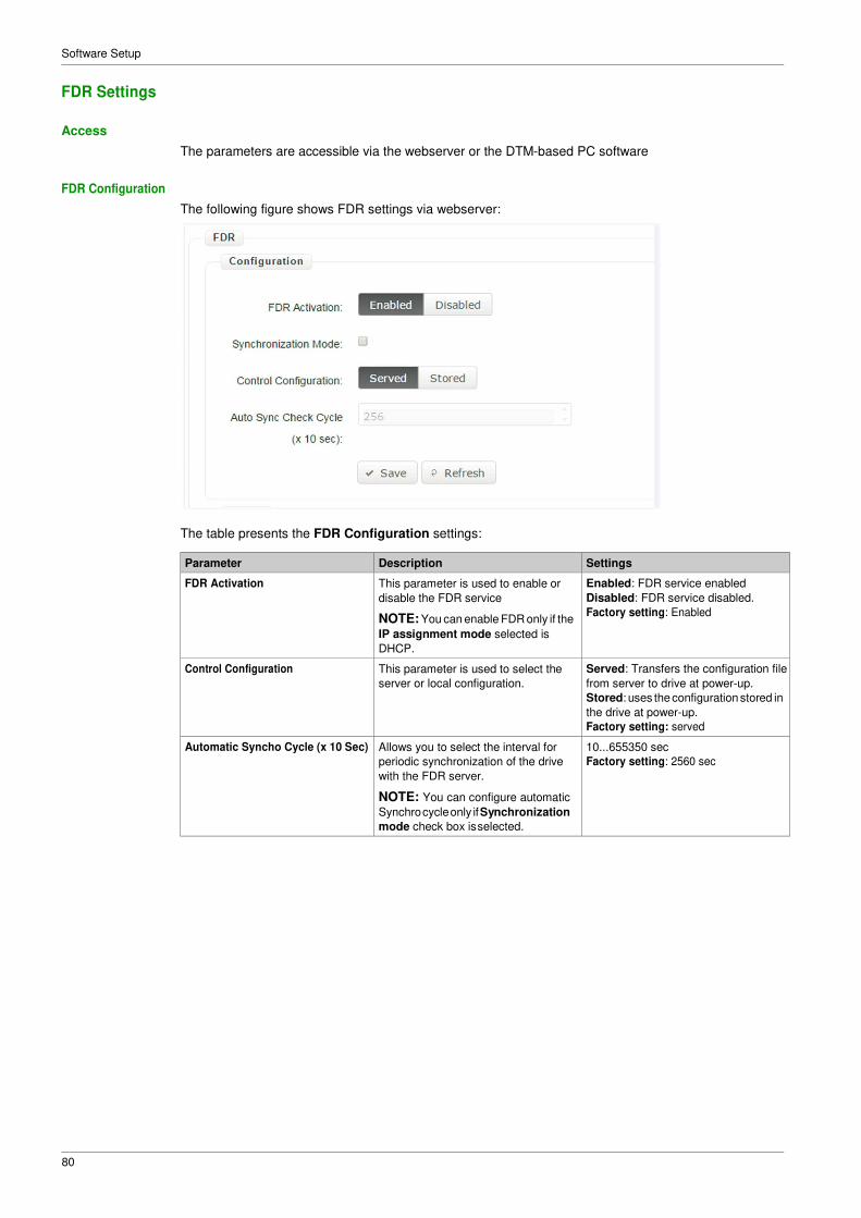
FDR Settings
Access
The parameters are accessible via the webserver or the DTM-based PC software
FDR Configuration
The following figure shows FDR settings via webserver:
The table presents the FDR Configuration settings:
Parameter Description Settings
FDR Activation This parameter is used to enable or
disable the FDR service
NOTE: You can enable FDR only if the
IP assignment mode selected is
DHCP.
Enabled: FDR service enabled
Disabled: FDR service disabled.
Factory setting: Enabled
Control Configuration This parameter is used to select the
server or local configuration.
Served: Transfers the configuration file
from server to drive at power-up.
Stored: uses the configuration stored in
the drive at power-up.
Factory setting: served
Automatic Syncho Cycle (x 10 Sec) Allows you to select the interval for
periodic synchronization of the drive
with the FDR server.
NOTE: You can configure automatic
Synchro cycle only if Synchronization
mode check box is selected.
10...655350 sec
Factory setting: 2560 sec
81
Software Setup
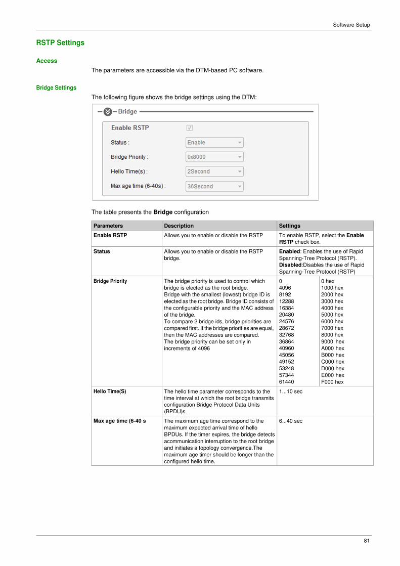
RSTP Settings
Access
The parameters are accessible via the DTM-based PC software.
Bridge Settings
The following figure shows the bridge settings using the DTM:
The table presents the Bridge configuration
Parameters Description Settings
Enable RSTP Allows you to enable or disable the RSTP To enable RSTP, select the Enable
RSTP check box.
Status Allows you to enable or disable the RSTP
bridge.
Enabled: Enables the use of Rapid
Spanning-Tree Protocol (RSTP).
Disabled:Disables the use of Rapid
Spanning-Tree Protocol (RSTP)
Bridge Priority The bridge priority is used to control which
bridge is elected as the root bridge.
Bridge with the smallest (lowest) bridge ID is
elected as the root bridge. Bridge ID consists of
the configurable priority and the MAC address
of the bridge.
To compare 2 bridge ids, bridge priorities are
compared first. If the bridge priorities are equal,
then the MAC addresses are compared.
The bridge priority can be set only in
increments of 4096
0
4096
8192
12288
16384
20480
24576
28672
32768
36864
40960
45056
49152
53248
57344
61440
0 hex
1000 hex
2000 hex
3000 hex
4000 hex
5000 hex
6000 hex
7000 hex
8000 hex
9000 hex
A000 hex
B000 hex
C000 hex
D000 hex
E000 hex
F000 hex
Hello Time(S) The hello time parameter corresponds to the
time interval at which the root bridge transmits
configuration Bridge Protocol Data Units
(BPDU)s.
1...10 sec
Max age time (6-40 s The maximum age time correspond to the
maximum expected arrival time of hello
BPDUs. If the timer expires, the bridge detects
acommunication interruption to the root bridge
and initiates a topology convergence.The
maximum age timer should be longer than the
configured hello time.
6...40 sec
82
Software Setup
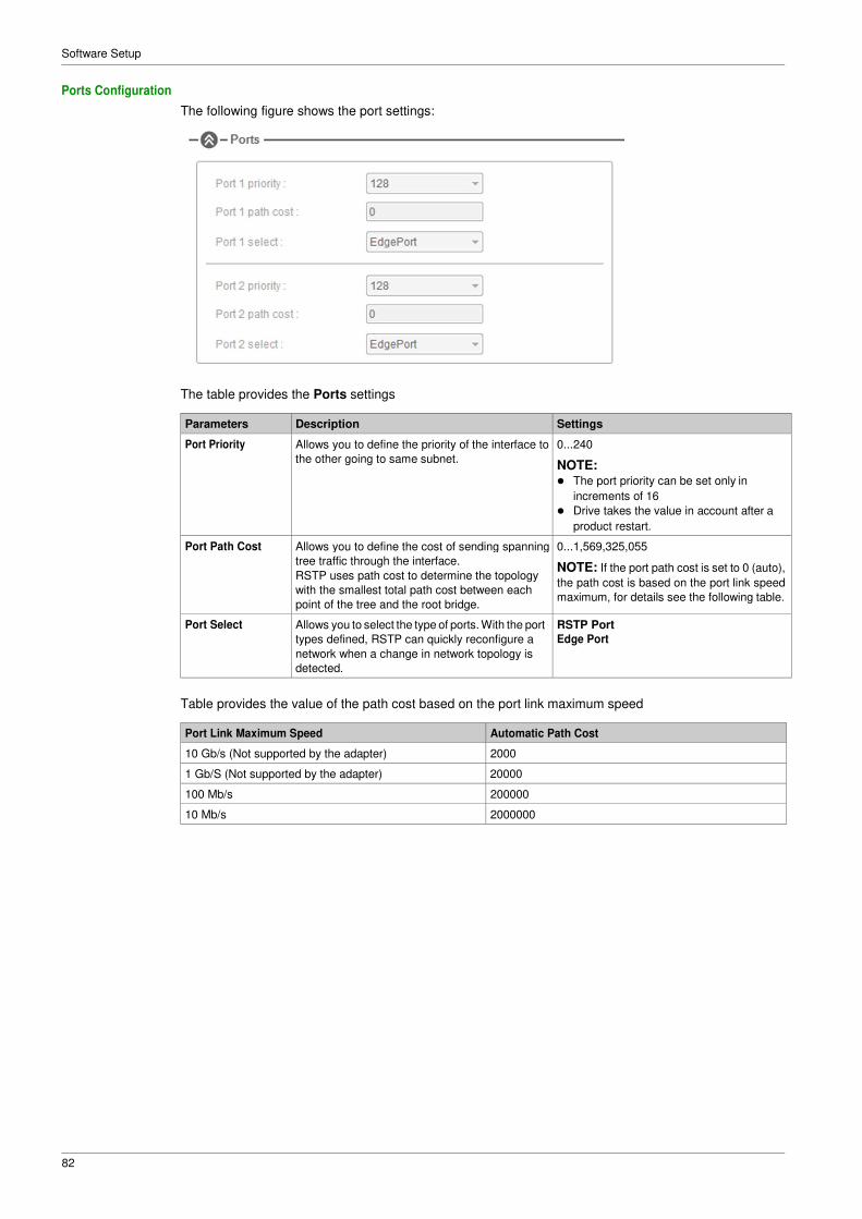
Ports Configuration
The following figure shows the port settings:
The table provides the Ports settings
Parameters Description Settings
Port Priority Allows you to define the priority of the interface to
the other going to same subnet.
0...240
NOTE: � The port priority can be set only in
increments of 16
� Drive takes the value in account after a
product restart.
Port Path Cost Allows you to define the cost of sending spanning
tree traffic through the interface.
RSTP uses path cost to determine the topology
with the smallest total path cost between each
point of the tree and the root bridge.
0...1,569,325,055
NOTE: If the port path cost is set to 0 (auto),
the path cost is based on the port link speed
maximum, for details see the following table.
Port Select Allows you to select the type of ports. With the port
types defined, RSTP can quickly reconfigure a
network when a change in network topology is
detected.
RSTP Port
Edge Port
Table provides the value of the path cost based on the port link maximum speed
Port Link Maximum Speed Automatic Path Cost
10 Gb/s (Not supported by the adapter) 2000
1 Gb/S (Not supported by the adapter) 20000
100 Mb/s 200000
10 Mb/s 2000000
83
Software Setup
Configuring I/O Scanning
Description
The drive I/O scanning service can be enabled or disabled with the DTM-based PC software.
It is not possible to modify the assignment of the I/O scanning periodic variables using the display terminal.
To configure I/O scanning, use the DTM-based PC software.
84
Software Setup
DNS Settings
Description
The Domain Name System (DNS) is a distributed naming system for devices connected to the network.
It translates domain names to IP addresses for locating the devices easily on the network.
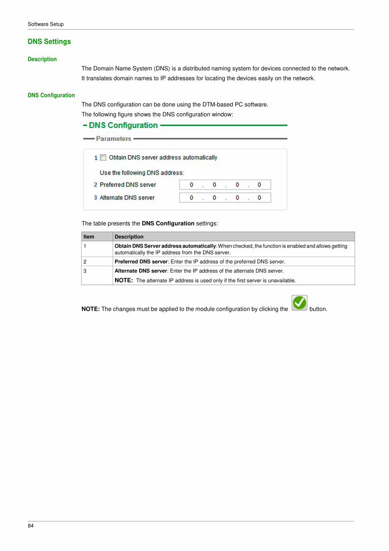
DNS Configuration
The DNS configuration can be done using the DTM-based PC software.
The following figure shows the DNS configuration window:
The table presents the DNS Configuration settings:
Item Description
1 Obtain DNS Server address automatically: When checked, the function is enabled and allows getting
automatically the IP address from the DNS server.
2 Preferred DNS server: Enter the IP address of the preferred DNS server.
3 Alternate DNS server: Enter the IP address of the alternate DNS server.
NOTE: The alternate IP address is used only if the first server is unavailable.
NOTE: The changes must be applied to the module configuration by clicking the button.
85
Software Setup
SNTP Settings
Description
The Simple Network Time Protocol (SNTP) is networking protocol for clock synchronization of devices
connected to the network.
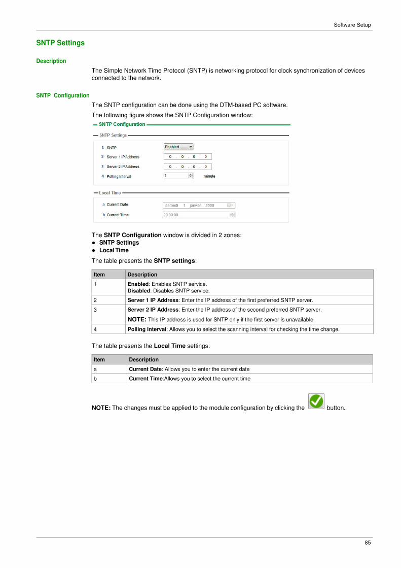
SNTP Configuration
The SNTP configuration can be done using the DTM-based PC software.
The following figure shows the SNTP Configuration window:
The SNTP Configuration window is divided in 2 zones:
� SNTP Settings
� Local Time
The table presents the SNTP settings:
Item Description
1 Enabled: Enables SNTP service.
Disabled: Disables SNTP service.
2 Server 1 IP Address: Enter the IP address of the first preferred SNTP server.
3 Server 2 IP Address: Enter the IP address of the second preferred SNTP server.
NOTE: This IP address is used for SNTP only if the first server is unavailable.
4 Polling Interval: Allows you to select the scanning interval for checking the time change.
The table presents the Local Time settings:
Item Description
a Current Date: Allows you to enter the current date
b Current Time:Allows you to select the current time
NOTE: The changes must be applied to the module configuration by clicking the button.
86
Software Setup
SNMP Settings
Description
Simple Network Management Protocol (SNMP) is an internet-standard protocol used to manage devices
on IP networks.
It is used for collecting and organizing information about the devices on the network.
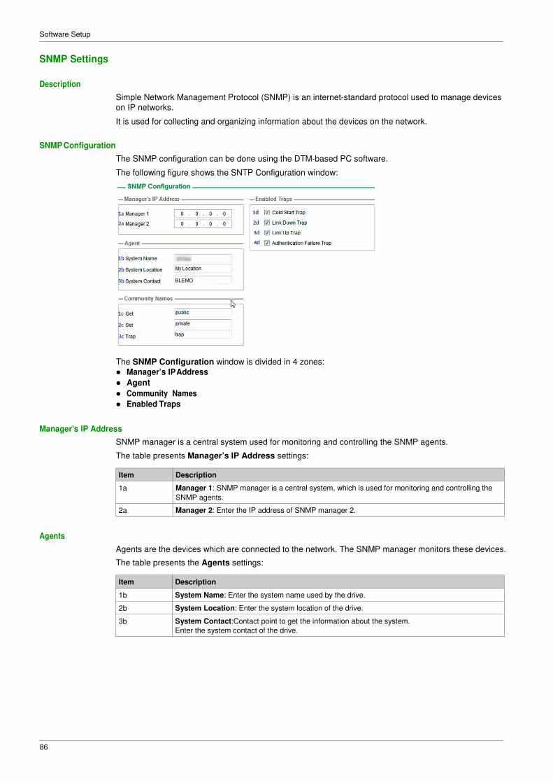
SNMP Configuration
The SNMP configuration can be done using the DTM-based PC software.
The following figure shows the SNTP Configuration window:
The SNMP Configuration window is divided in 4 zones:
� Manager’s IP Address
� Agent
� Community Names
� Enabled Traps
Manager's IP Address
SNMP manager is a central system used for monitoring and controlling the SNMP agents.
The table presents Manager’s IP Address settings:
Item Description
1a Manager 1: SNMP manager is a central system, which is used for monitoring and controlling the
SNMP agents.
2a Manager 2: Enter the IP address of SNMP manager 2.
Agents
Agents are the devices which are connected to the network. The SNMP manager monitors these devices.
The table presents the Agents settings:
Item Description
1b System Name: Enter the system name used by the drive.
2b System Location: Enter the system location of the drive.
3b System Contact:Contact point to get the information about the system.
Enter the system contact of the drive.
BLEMO
87
Software Setup
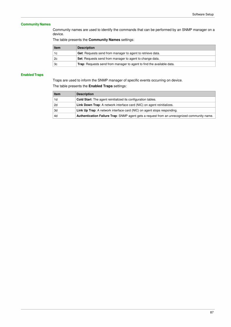
Community Names
Community names are used to identify the commands that can be performed by an SNMP manager on a
device.
The table presents the Community Names settings:
Item Description
1c Get: Requests send from manager to agent to retrieve data.
2c Set: Requests send from manager to agent to change data.
3c Trap: Requests send from manager to agent to find the available data.
Enabled Traps
Traps are used to inform the SNMP manager of specific events occurring on device.
The table presents the Enabled Traps settings:
Item Description
1d Cold Start: The agent reinitialized its configuration tables.
2d Link Down Trap: A network interface card (NIC) on agent reinitializes.
3d Link Up Trap: A network interface card (NIC) on agent stops responding.
4d Authentication Failure Trap: SNMP agent gets a request from an unrecognized community name.
88
Software Setup
Section 4.3 Fast Device Replacement
What Is in This Section?
This section contains the following topics:
Topic Page
Presentation 89
Startup Detailed Behavior 90
FDR Operation Behavior 91
Local Configuration 92
Downloaded Configuration 93
89
Software Setup
Presentation
FDR Service
The FDR (Fast Device Replacement) service is used to simplify the maintenance of drives connected to
an Ethernet network. In the event of a drive not working correctly, this service automatically reconfigures
its replacement.
The new drive (FDR client) retrieves:
� Its IP addresses and the FDR file path from a DHCP server
� The FDR file from an FTP server if the drive is not configured in local configuration
In practice, the DHCP server and the FTP server are the same device (PAC M580, M340 PLC, or
dedicated PCs).
The FDR file contains:
� The Ethernet parameters (configuration of I/O scanning, FDR, and so on)
� The drive parameters (drive, functions, application, and so on)
The FDR service is based on identification of the device by a Device Name. In the case of the drive, this
is represented by the [DEVICE NAME] PAn parameter.
The configuration of the FDR service is accessible via embedded webserver or DTM-based software or
Graphic Display Terminal.
NOTE: Check that all the network devices have different Device Name.
The FDR server controls duplication of Device Name (it does not assign an IP address that has already
been assigned and is active).
If the same IP address is supplied on 2 devices, the second should trigger an IP address duplication (network management detected error which triggers an [Fieldbus Error] EPF2 by default).
If the FDR service has been enabled, the Ethernet adapter attempts to restore its IP addresses on each
power-up. Each time the procedure has detected error, the Ethernet adapter reiterates its FDR requests
(DHCP).
After assigning the Ethernet adapter IP addresses, if the configuration is not downloaded successfully, the Ethernet adapter triggers a [FDR2 Error] FDR2.
90
Software Setup
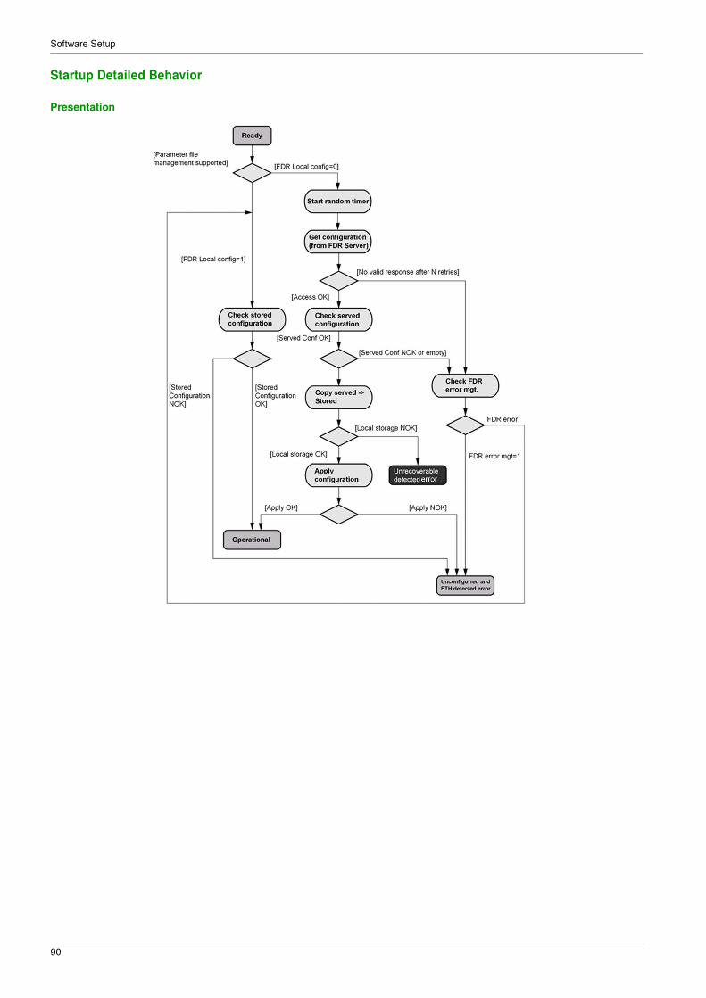
Startup Detailed Behavior
Presentation
91
Software Setup
FDR Operation Behavior
92
Software Setup
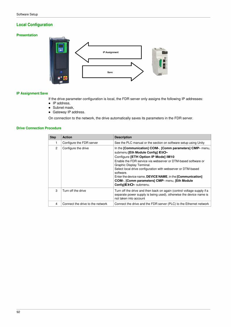
Local Configuration
Presentation
IP Assignment Save
If the drive parameter configuration is local, the FDR server only assigns the following IP addresses:
� IP address,
� Subnet mask,
� Gateway IP address.
On connection to the network, the drive automatically saves its parameters in the FDR server.
Drive Connection Procedure
Step Action Description
1 Configure the FDR server See the PLC manual or the section on software setup using Unity
2 Configure the drive In the [Communication] COM-, [Comm parameters] CMP- menu,
submenu:[Eth Module Config] EtO-
Configure [ETH Option IP Mode] iM10
Enable the FDR service via webserver or DTM-based software or
Graphic Display Terminal.
Select local drive configuration with webserver or DTM-based
software.
Enter the device name, DEVICE NAME, in the [Communication]
COM-, [Comm parameters] CMP- menu, [Eth Module
Config]EtO- submenu.
3 Turn off the drive Turn off the drive and then back on again (control voltage supply if a
separate power supply is being used), otherwise the device name is
not taken into account
4 Connect the drive to the network Connect the drive and the FDR server (PLC) to the Ethernet network
93
Software Setup
Downloaded Configuration
Presentation
IP Assignment Save
If the drive parameter configuration has been downloaded, the FDR server assigns the following
addresses:
� IP address,
� Subnet mask,
� Gateway IP address,
� FDR server IP address.
Periodic Saving
Periodic saving of the drive configuration can be configured on the FDR server in either local configuration
or downloaded configuration mode
Using the embedded webserver or the DTM-based software:
� Set FDR synchronization to automatic mode
� Set the synchronization cycle time
NOTE: Saving too often overburden the fieldbus and adversely affects its performance (factory setting:
2.560 s.).
Limitations
The FDR service is able to store the current configuration of the drive, but does not provide the possibility
to store multi-parameters configurations.
94
Software Setup
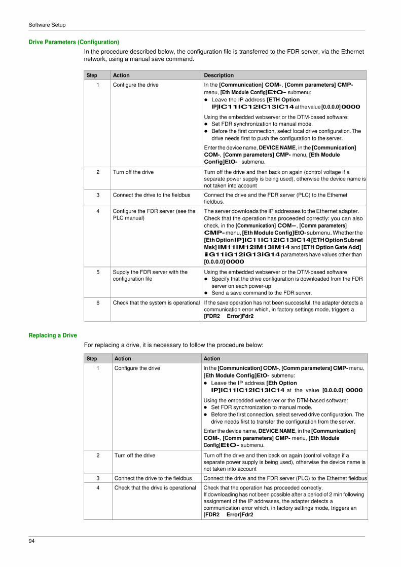
Drive Parameters (Configuration)
In the procedure described below, the configuration file is transferred to the FDR server, via the Ethernet
network, using a manual save command.
Step Action Description
1 Configure the drive In the [Communication] COM-, [Comm parameters] CMP-
menu, [Eth Module Config]EtO- submenu:
� Leave the IP address [ETH Option
IP]IC11IC12IC13IC14 at the value [0.0.0.0] 0000
Using the embedded webserver or the DTM-based software:
� Set FDR synchronization to manual mode.
� Before the first connection, select local drive configuration. The
drive needs first to push the configuration to the server.
Enter the device name, DEVICE NAME, in the [Communication]
COM-, [Comm parameters] CMP- menu, [Eth Module
Config]EtO- submenu.
2 Turn off the drive Turn off the drive and then back on again (control voltage if a
separate power supply is being used), otherwise the device name is
not taken into account
3 Connect the drive to the fieldbus Connect the drive and the FDR server (PLC) to the Ethernet
fieldbus.
4 Configure the FDR server (see the
PLC manual)
The server downloads the IP addresses to the Ethernet adapter.
Check that the operation has proceeded correctly: you can also
check, in the [Communication] COM-, [Comm parameters]
CMP- menu, [Eth Module Config]EtO- submenu. Whether the
The values of the [Fieldbus Interrupt Resp] CLL parameter, which does not trigger a transition to the
operating state fault are:
Value Meaning
[Ignore] nO Detected error ignored
[Per STT] Stt Stop according to configuration of [Type of stop] Stt
[Fallback Speed] LFF Change to fallback speed, maintained as long as the detected error
persists and the run command has not been removed
[Speed maintained] rLS The drive maintains the speed at the time the detected error occurred, as
long as the detected error persists, and the run command has not been
removed
The fallback speed can be configured in the [Complete settings] CSt-, [Error/Warning handling]
CSWM- menu, [Fallback speed] LFF- submenu, using the [FallbackSpeed] LFF parameter.
WARNING LOSS OF CONTROL
If this parameter is set to nO, fieldbus communication monitoring is disabled.
Only use this setting after a thorough risk assessment in compliance with all regulations and standards
that apply to the device and to the application.
Only use this setting for tests during commissioning.
Verify that communication monitoring has been re-enabled before completing the commissioning
procedure and performing the final commissioning test.
Failure to follow these instructions can result in death, serious injury, or equipment damage.
125
Operations
Detected Errors
Parameter Description Possible Values Terminal Display
[Fieldbus Com This parameter is 1: Modbus TCP timeout [1] 1
Interrupt]CnF Written used to indicate that 4: Ethernet IP timeout [4] 4
to the device fieldbus error has been detected. When the detected error is active, the value corresponds to the cause of the error. When the cause of the error is no longer active, the value is reset to 0. [Fieldbus Error] EPF2 − 1: Invalid IP address [1] 1
2: Duplicate IP address [2] 2
[FDR 2 Error] FDR2 This parameter is
used to indicate that
an error has been
detected during FDR
procedure. Details
about this error are
provided using FDR1
parameter.
0: No error
1: Server timeout
2: No file on server
3: Corrupted file on server
4: Empty file on server
5: Invalid file on drive
6: CRC error
7: Version incompatibility between
drive and file.
9: No file on drive
10: File size reading error on server
11: Drive cannot open the file
12: Drive cannot read the file
13: File incompatibility
14: Drive name is invalid
15: Incorrect file size on server
16: Drive cannot write the file
17: Server cannot write the file
[No error]
[Server Timeout]
[Server No File]
[Server Corrupt File]
[Server Empty File]
[Drive Invalid File]
[CRC Error]
[Version Incompatibility]
[Drive No File]
[Server Reading Size]
[Drive Opening File]
[Drive Reading File]
[Incompatibility]
[Drive Invalid Name]
[Server Incorrect File Size]
[Drive Writing File]
[Server Writing File]
126
Operations
Section 5.2 Operating Modes
What Is in This Section?
This section contains the following topics:
Topic Page
Configuring the Control Channel 127
Configuration of the Drive for Operation in I/O Profile 128
Configuration of the Drive for Operation with CiA 402 Profile in Combined Mode 129
Configuration of the Drive for Operation with CiA 402 Profile in Separate Mode 130
127
Operations
Configuring the Control Channel
Overview
This chapter explains how to configure the drive for operation from communication network through three
following examples.
� I/O mode - a simple command word (based on forward, reverse, and reset binary commands).
� Combined mode (with native profile CiA 402) - Both reference value and command word come from the
communication network.
� Separate (with native profile CiA 402) - reference value and command come from separate sources: for
example, the command (in CiA 402) comes from the communication network and the reference value
from the HMI.
128
Operations
Configuration of the Drive for Operation in I/O Profile
Description
For the I/O profile, here is a simple example, which can be extended with additional features. The
command word is made of run forward (bit 0 of CMd), run reverse (bit 1 of CMd), and the function fault
reset (bit 7 of CMd). The reference frequency is given by Graphic Display Terminal.
The settings are the following:
[Ref Freq 1 Config] Fr1 [HMI] HMI
[Control Mode] CHCF [I/O profile] IO
[Command switching] CCS [Cmd Channel 1]CD1
[Cmd channel 1] Cd1 [Com. Module] nEt
The bits of the command word can now be configured.
In the [Command and Reference] CrP- menu configure:
In the [Error/Warning handling] CSWM- menu, [Fault reset] rSt-?submenu, configure:
[Fault Reset Assign] rSF [CD07] Cd07
129
Operations
Configuration of the Drive for Operation with CiA 402 Profile in Combined Mode
Description
This section describes how to configure the settings of the drive if it is controlled in CiA 402 mode. The
example focuses on the not separate mode. Additional modes are detailed in the drive programming
manual.
In the [Complete settings] CSt- menu, [Command and reference] CrP- submenu:
� [Ref Freq Channel 1] Fr1: is set on according to the communication source you can choose in the
following table:
Origin of the Control Ref1 Channel Setting
Ethernet module [Com. Module] nEt
� [Freq Switch Assign] rFC is set to default value ([Ref Freq 1 Config] Fr1).
� [Control Mode] CHCF: defines if the drive operates in combined mode (reference and command from
the same channel).
For the current example, [Control Mode] CHCF is adjusted to [Not separ.] SIM as reference and control
are originated from the communication network:
Profile Ref1 Channel setting
CiA 402 combined mode [Not separ.] SIM
CiA 402 separate mode [Separate] SEp
I/O profile [I/O profile] IO
Operations
130
Configuration of the Drive for Operation with CiA 402 Profile in Separate Mode
Description
Alternate combinations are possible, see the drive programming manual for the list of possible settings.
For example:
The drive is controlled from the communication but the reference value is adjusted on the display terminal.
The control word comes from the controller and is written according to CiA 402 profile.
The settings are as shown in the table:
[Ref Freq 1 Config] Fr1 [HMI] HMI
[Control Mode] CHCF [Separate] SEp
[Cmd channel 1] Cd1 [Com. Module] nEt
131
Chapter 6 Diagnostic and Troubleshooting
What Is in This Chapter?
This chapter contains the following topics:
Topic Page
Fieldbus Status LEDs 132
Connection for Fieldbus Mode 134
Fieldbus Functions Test 135
Control-Signal Diagnostics 137
Diagnostic and Troubleshooting
132
Fieldbus Status LEDs
LED Indicators
LED Description
LNK1 and LNK2
The following figure describes the LEDs status for fieldbus monitoring:
Item LED Description
1 LNK1 Indicates port A activity.
2 MS Indicates module status.
3 NS Indicates network status.
4 LNK2 Indicates port B activity.
These LEDs indicate the status of the Ethernet adapter ports:
Color & status Description
OFF No link
Blinking
Green/Yellow
Power on testing
Green ON Link established at 100 Mbit/s
Yellow ON Link established at 10 Mbit/s
Blinking Green Fieldbus activity at 100 Mbit/s
Blinking Yellow Fieldbus activity at 10 Mbit/s
NS: Network Status
This LED indicates the status of the fieldbus.
Color & status Description
OFF The device does not have an IP address or powered off
Blinking Green/Red Power on testing
Green ON A connection is established to control the command word.
Blinking Green Device has a valid IP, but no command word connection.
Red ON Duplicated IP
Blinking Red An established connection to control the command word is closed or timed out
Diagnostic and Troubleshooting
133
MS: Module Status
This LED indicates the status of the adapter
Color & status Description
OFF No power is supplied to the device
Blinking Green/Red Power on testing
Green ON The device is operating correctly.
Blinking Green Device has not been configured.
Blinking red The device has detected a recoverable minor detected error.
Red ON The device has detected a non-recoverable major detected error.
Diagnostic and Troubleshooting
134
Connection for Fieldbus Mode
Description
If the product cannot be addressed via the fieldbus, first check the connections. The product manuals
contains the technical data of the device and information on fieldbus and device installation.
Verify the following:
� Power connections to the device
� Fieldbus cable and fieldbus wiring
� Fieldbus connection to the device
Diagnostic and Troubleshooting
135
Fieldbus Functions Test
Channels for Commands and Reference Values
All the drive commands and reference value parameters are managed on a channel-by-channel basis.
Parameter Name Parameter Code
Taken Into Account
by the Drive
Modbus
Serial
CANopen Fieldbus Module Ethernet
Embedded
Control word CMd CMd1 CMd2 CMd3 CMd5
Extended control
word
CMI CMI1 CMI2 CMI3 CMI5
Reference speed
(rpm)
LFrd LFd1 LFd2 LFd3 LFd5
Reference
frequency
(0.1 Hz)
LFr LFr1 LFr2 LFr3 LFr5
Reference value
for torque control
mode (0.1% of the
nominal torque)(1)
LTR LTR1 LTR2 LTR3 LTR5
Reference value
supplied by PI
controller
PISP PIr1 PIr2 PIr3 PIr5
Reference value
supplied by analog
multiplier
function
MFr MFr1 MFr2 MFr3 MFr5
(1): If available
Fieldbus Monitoring Criteria
The fieldbus is monitored according to the protocol-specific criteria.
Protocol Criteria Related Detected Error
Ethernet module FDR detected error
IP address duplication detected error
Adjustable time-out for received control
word (I/O scanning or messaging)
Fieldbus overload
[Fieldbus Error]EPF2
[FDR 2 Error]FDR2
[Fieldbus Com Interrupt] CnF
Diagnostic and Troubleshooting
136
Monitoring of Communication Channels
Communication channels are monitored if they are involved in one of the following parameters: � The control word ([Cmd Register] CMd) from the active command channel
� The control word containing the command switch (bit configured on [Cmd switching] CCS)
� The control word containing the switch for reference value 1'1B (bit configured on [Ref 1B switching]
rCb)
� The control word containing the switch for reference value 1'2 (bit configured on [Freq Switch Assign]
rFC)
� The reference frequency or reference speed ([Ref Frequency] LFr or LFRD: Nominal speed value)
from the active channel for reference value
� Summing reference frequency or reference speed ([Ref Frequency] LFr or LFRD: Nominal speed
value) 2 (assigned to [Summing Input 2] SA2)
� Summing reference frequency or reference speed ([Ref Frequency] LFr or LFRD: Nominal speed
value) 3 (assigned to [Summing Input 3] SA3)
� Subtracting reference frequency or reference speed ([Ref Frequency] LFr or LFRD: Nominal speed
value) 2 (assigned to [Subtract Ref Freq 2] dA2)
� Subtracting reference frequency or reference speed ([Ref Frequency] LFr or LFRD: Nominal speed
value) 3 (assigned to [Subtract Ref Freq 3] dA3)
� The reference value given by the PID controller (PISP)
� The PID controller feedback ([AI Virtual 1] AIU1)
� The multiplication coefficient of the reference values ([Multiplying coeff.] MFr) 2 (assigned to [Ref Freq
2 Multiply] MA2)
� The multiplication coefficient of the reference values ([Multiplying coeff.] MFr) 3 (assigned to [Ref Freq
3 Multiply] MA3)
As soon as one of these parameters has been written once to a communication channel, it activates
monitoring for that channel.
If a communication warning is sent (in accordance with the protocol criteria) by a monitored port or fieldbus
module, the drive triggers a communication interruption.
The drive reacts according to the communication interruption configuration (operating state Fault,
maintenance, fallback, and so on)
If a communication warning occurs on a channel that is not being monitored, the drive does not trigger a
communication interruption.
Enabling of Communication Channels
A communication channel is enabled once all the parameters involved have been written at least one
time.The drive is only able to start if all channels involved in command and reference value are enabled.
For example:
A drive in DSP402 profile is connected to an active communication channel.
It is mandatory to write at least 1 time the reference value and the command in order to switch from 4-
Switched on to 5-Operation enabled state.
A communication channel is disabled:
� In the event of a communication warning.
� In forced local mode.
NOTE: On exiting forced local mode:
� The drive copies the run commands, the direction, and the forced local reference value to the active
channel (maintained).
� Monitoring of the active channels for the command and reference value resumes following a time delay
[Time-out forc. local] FLOt.
� Drive control only takes effect once the d rive has received the reference and the command from the
active channels.
Diagnostic and Troubleshooting
137
Control-Signal Diagnostics
Introduction
On the display terminal, the [Display] MON-, [Communication map] CMM- submenu can be used to
display control-signal diagnostic information between the drive and the controller:
� Active command channel [Command Channel] CMdC
� Value of the control word [Cmd Register] CMd from the active command channel [Command Channel]
CMdC
� Active reference frequency channel [Ref Freq Channel] rFCC
� Value of the reference frequency [Pre-Ramp Ref Freq] FrH from the active target channel [Ref Freq
Channel] rFCC
� Value of the operating state word [CIA402 State Reg] EtA
� Specific data for all available fieldbusses are in dedicated submenus.
� In the [Command word image] CWI- submenu: control words from all channels
� In the [Freq. ref. word map] rWI- submenu: reference frequency values produced by all channels
Control Word Display
The [Command Channel] CMdC parameter indicates the active command channel.
The [Cmd Register] CMd parameter indicates the hexadecimal value of the control word (CMD) used to
control the drive.
The [Command word image] CWI- submenu ([COM. Module cmd.] CMd3) parameter is used to
display the hexadecimal value of the control word from the fieldbus module.
Reference Frequency Display
The [Ref Freq Channel] rFCC parameter indicates the active channel for reference frequency.
The [Ref Frequency] LFr parameter indicates the value (in 0.1 Hz units) of the reference frequency used
to control the drive.
The [Freq. ref. word map] rWI- submenu ([COM Module Ref Freq] LFr3) parameter is used to
display the value (in 0.1 Hz units) of the reference frequency from the fieldbus.
Operating State Word Display
The [CIA402 State Reg] EtA parameter gives the value of the operating state word (ETA).
The table provides the bit details of ETA parameter:
Bit Description
DRIVECOM Status word
Bit0 = 1 Ready to switch on
Bit1 = 1 Switched on
Bit2 = 1 Operation enabled
Bit3 = 1 Operating state fault
Bit4 = 1 Power stage is switched on
Bit5 = 0 Quick stop
Bit6 = 1 Switch on disabled
Bit7 = 1 Warning
Bit8 = 1 Drivecom reserved
Bit9 = 0 Forced local mode in progress
Bit10 = 1 Reference value reached (steady state)
Bit11 = 1 Reference value exceeded (< LSP or > HSP)
Bit12 Reserved
Bit13 Reserved
Bit14 = 1 Stop imposed via STOP key
Bit15 = 0 Motor rotation in forward direction (or stopped)
Diagnostic and Troubleshooting
138
139
Glossary
A
Abbreviations
CAN
COB
COB ID
Req. = Required
Opt. = Optional
C
Controller Area Network is an internally standardized serial bus system
Communication Object. A unit of transportation in a CAN network. Data must be sent across a CAN
Network inside a COB. There are 2048 different COB's in a CAN network. A COB can contain at most
8 bytes of data.
Each COB is uniquely identified in a CAN network by a number called the COB Identifier (COB-ID).
D
Display terminal
DP
DPWS
Error
The display terminal menus are shown in square brackets.
For example: [Communication]
The codes are shown in round brackets.
For example: COM-
Parameter names are displayed on the display terminal in square brackets.
For example: [Fallback Speed]
Parameter codes are displayed in round brackets.
For example: LFF
Decentralized Periphery
Device Profile for Web Service
E
Discrepancy between a detected (computed, measured, or signaled) value or condition and the specified
or theoretically correct value or condition.
F
Factory setting
Fault
Fault Reset
Factory settings when the product is shipped
Fault is an operating state. If the monitoring functions detect an error, a transition to this operating state is
triggered, depending on the error class. A "Fault reset" is required to exit this operating state after the
cause of the detected error has been removed. Further information can be found in the pertinent standards
such as IEC 61800-7, ODVA Common Industrial Protocol (CIP).
A function used to restore the drive to an operational state after a detected error is cleared by removing
the cause of the error so that the error is no longer active.
140
Glossary
L
LSB
Least Significant Byte
M
Monitoring function
MS0, MS1
MSB
NMT
Monitoring functions acquire a value continuously or cyclically (for example, by measuring) in order to
check whether it is within permissible limits. Monitoring functions are used for error detection.
Number of a master in the network.
Most Significant Byte
N
Network Management. One of the service elements of the application layer in the CAN Reference Model.
The NMT serves to configure, initialize, and handle detected errors in a CAN network.
P
Parameter
PDO
PELV
PLC
PNO
Power stage
QoS
Quick Stop
RPDO
SNMP
SNTP
Device data and values that can be read and set (to a certain extent) by the user.
Process Data Object
Protective Extra Low Voltage, low voltage with isolation. For more information: IEC 60364-4-41
Programmable logic controller
PROFIBUS Nutzerorganisation e.V. (PROFIBUS User organization).
The power stage controls the motor. The power stage generates current for controlling the motor.
Q
Quality of Service
The quick Stop function can be used for fast deceleration of a movement as a response to a detected error
or via a command.
R
Receive PDO
S
Simple Network Management Protocol
Simple Network Time Protocol
141
Glossary
SYNC Synchronization Object
T
TPDO
Transmit PDO
W
Warning
If the term is used outside the context of safety instructions, a warning alerts to a potential problem that
was detected by a monitoring function. A warning does not cause a transition of the operating state.
Z
Zone of operation
This term is used in conjunction with the description of specific hazards, and is defined as it is for a hazard
zone or danger zone in the EC Machinery Directive (2006/42/EC) and in ISO 12100-1.