National Aeronautics and Space Administration www.nasa.gov ERA's Open Rotor Studies Including Shielding For Noise Reduction Environmentally Responsible Aviation Project Progress Towards Open Rotor Propulsion Technology Royal Aeronautical Society Headquarters No. 4 Hamilton Place, London, UK November 21, 2012 Dale Van Zante and Russell Thomas Presented by: Dr. Dale Van Zante Sub-Project Engineer for Propulsion Additional system analysis provided by the Subsonic Fixed Wing Project
Transcript
National Aeronautics and Space Administration
www.nasa.gov
ERA's Open Rotor Studies Including Shielding For Noise Reduction
Environmentally Responsible Aviation Project
Progress Towards Open Rotor Propulsion Technology
Royal Aeronautical Society Headquarters
No. 4 Hamilton Place, London, UK
November 21, 2012
Dale Van Zante and Russell Thomas
Presented by: Dr. Dale Van Zante
Sub-Project Engineer for Propulsion
Additional system analysis provided by the
Subsonic Fixed Wing Project
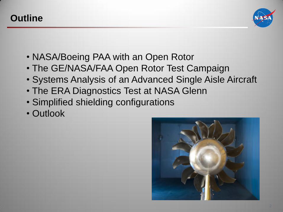
Outline
2
• NASA/Boeing PAA with an Open Rotor
• The GE/NASA/FAA Open Rotor Test Campaign
• Systems Analysis of an Advanced Single Aisle Aircraft
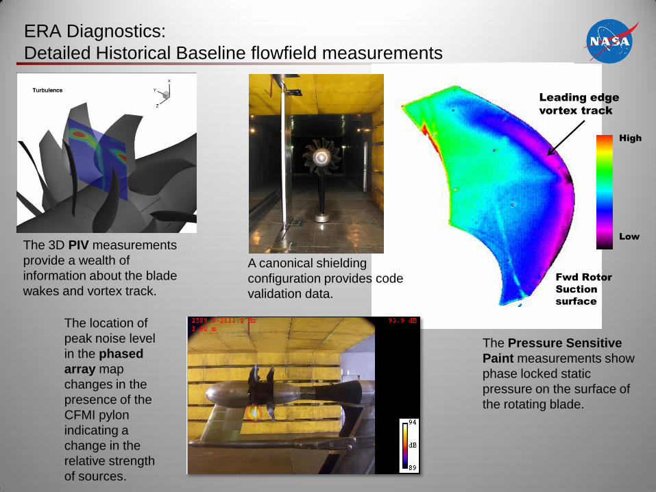
• The ERA Diagnostics Test at NASA Glenn
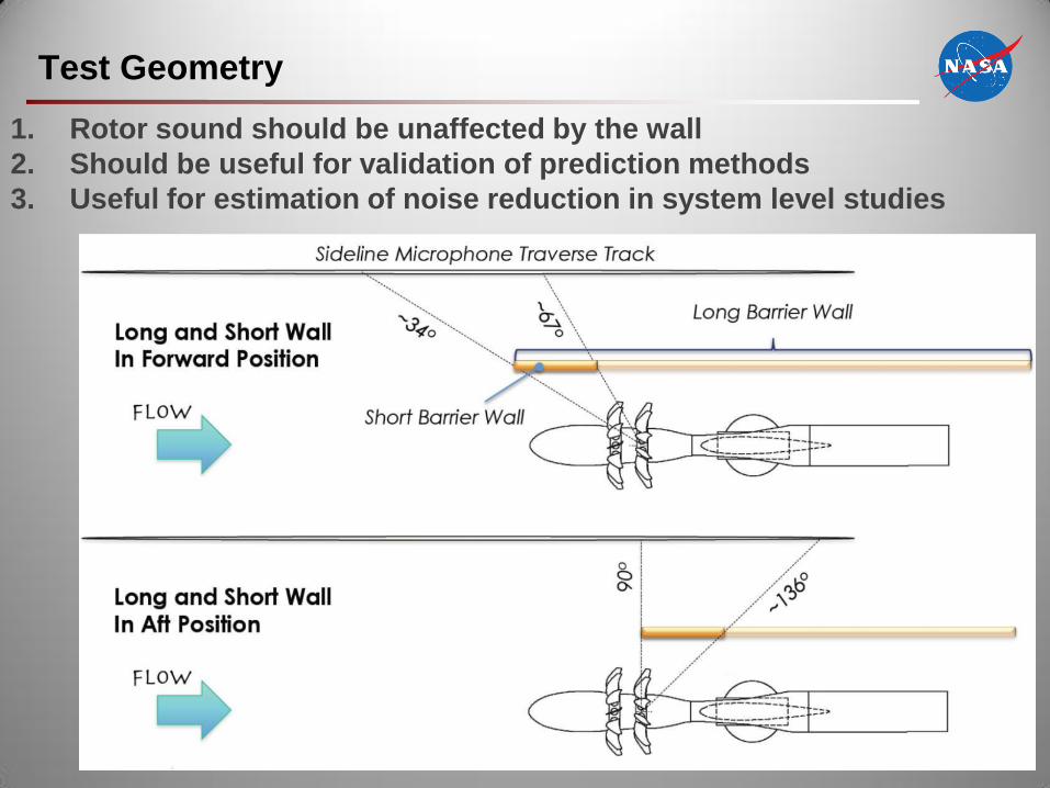
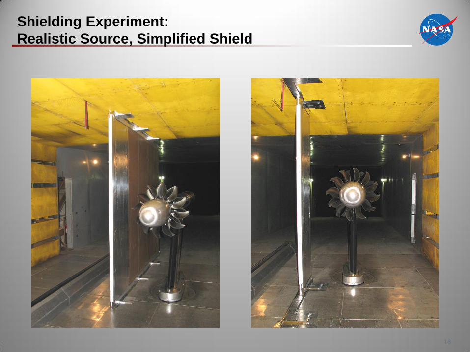
• Simplified shielding configurations
• Outlook
NASA/Boeing Open Rotor Propulsion Airframe
Aeroacoustic Integration Effects Test in 2010
3
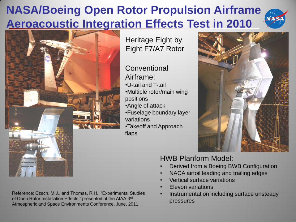
NASA/Boeing Open Rotor Propulsion Airframe
Aeroacoustic Integration Effects Test in 2010
Conventional
Airframe: •U-tail and T-tail
•Multiple rotor/main wing
positions
•Angle of attack
•Fuselage boundary layer
variations
•Takeoff and Approach
flaps
Heritage Eight by
Eight F7/A7 Rotor
HWB Planform Model: • Derived from a Boeing BWB Configuration
• NACA airfoil leading and trailing edges
• Vertical surface variations
• Elevon variations
• Instrumentation including surface unsteady
pressures
Reference: Czech, M.J., and Thomas, R.H., “Experimental Studies
of Open Rotor Installation Effects,” presented at the AIAA 3rd
Atmospheric and Space Environments Conference, June, 2011.
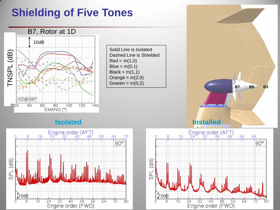
Shielding of Five Tones
B7, Rotor at 1D
TN
SP
L (
dB
)
B3 B5 B7
Solid Line is Isolated
Dashed Line is Shielded
Red = m(1,0)
Blue = m(0,1)
Black = m(1,1)
Orange = m(2,0)
Greeen = m(0,2)
10dB
Isolated Installed
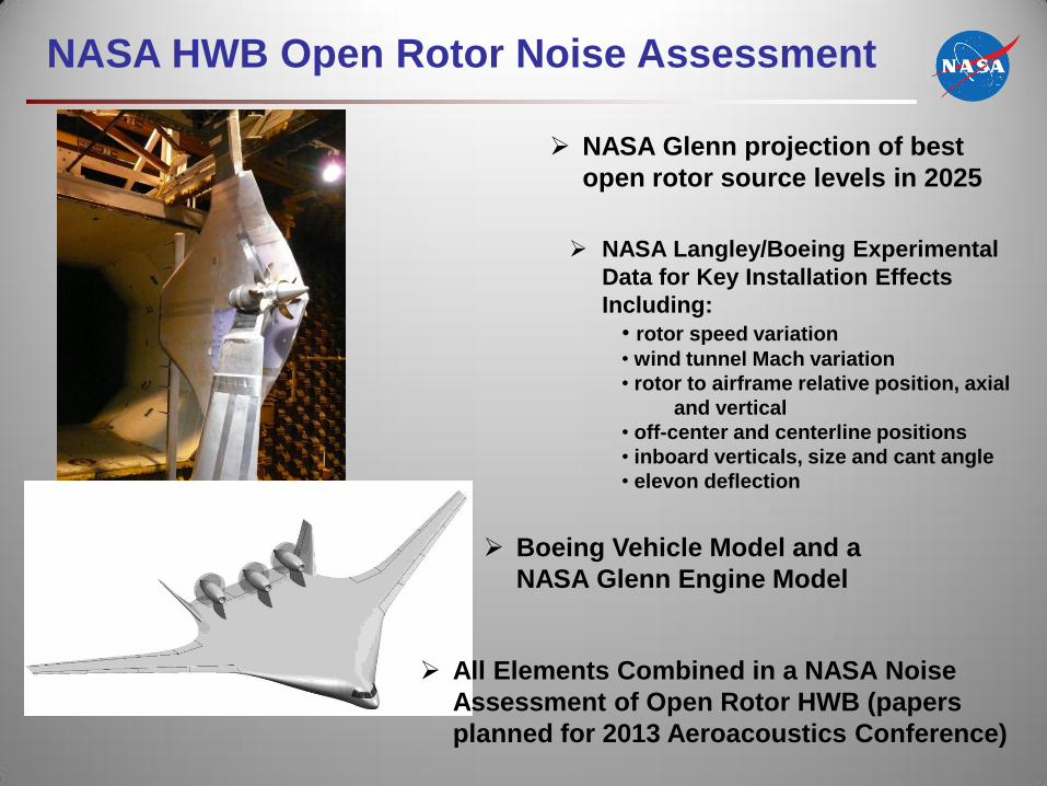
NASA HWB Open Rotor Noise Assessment
NASA Langley/Boeing Experimental
Data for Key Installation Effects
Including:
• rotor speed variation
• wind tunnel Mach variation
• rotor to airframe relative position, axial
and vertical
• off-center and centerline positions
• inboard verticals, size and cant angle
• elevon deflection
NASA Glenn projection of best
open rotor source levels in 2025
All Elements Combined in a NASA Noise
Assessment of Open Rotor HWB (papers
planned for 2013 Aeroacoustics Conference)
Boeing Vehicle Model and a
NASA Glenn Engine Model
The GE/NASA/FAA Collaboration on Open Rotor Testing
•Objective: Explore the design space for lower noise
while maintaining the high propulsive efficiency from a
counter-rotating open rotor system.
• Approach: A low-noise open rotor system is being tested in
collaboration with General Electric and CFM International, a 50/50
joint company between Snecma and GE. Candidate technologies for
lower noise will be investigated. Installation effects such as pylon
integration will be investigated in partnership with GE and the FAA.
Historical Baseline
Blade Set
12 x 10 blade count
Gen-1 Blade Sets (NASA/GE)
Historical Baseline
Modern Baseline
2 GE Advanced Designs
2 Snecma Designs
Gen-2 Blade Sets (NASA/FAA/GE)
6 GE Advanced Designs
Pylon wake mitigation
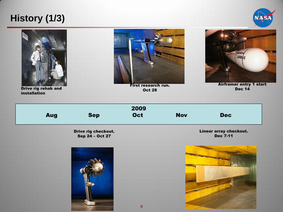
History (1/3)
8
2009
Aug Sep Oct Nov Dec
Drive rig rehab and
installation
Drive rig checkout.
Sep 24 – Oct 27
First research run.
Oct 28
Linear array checkout.
Dec 7-11
Airframer entry 1 start
Dec 14
History (2/3)
9
2010
Jan Feb Mar Apr May Jun Jul Aug Sep Oct Nov Dec
GE/Airbus test
complete.
Feb 12
Drive rig muffler
implementation.
ERA Diagnostics Test.
Jul 19 – Sep 7
Op
en R
oto
r In
sta
ll
In the 8
x6
GE/Boeing test.
Apr 5 – 28.
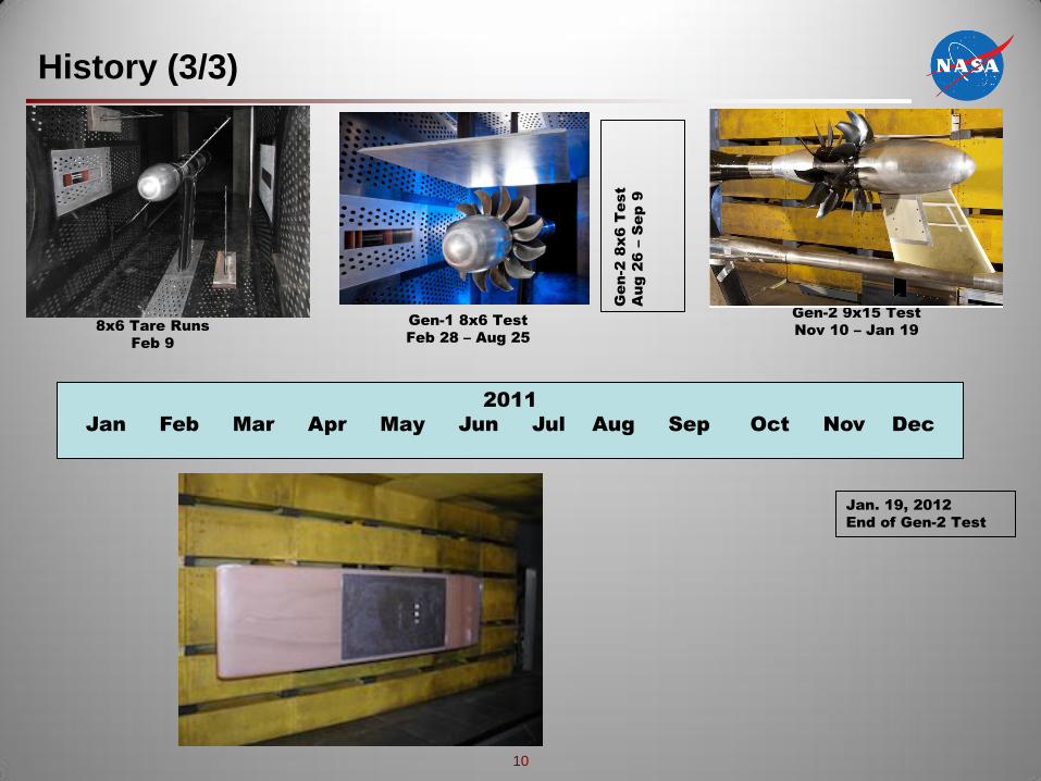
History (3/3)
10
2011
Jan Feb Mar Apr May Jun Jul Aug Sep Oct Nov Dec
Jan. 19, 2012
End of Gen-2 Test
Gen-2 8x6 T
est
Aug 26 – S
ep 9
Gen-1 8x6 Test
Feb 28 – Aug 25
8x6 Tare Runs
Feb 9
Gen-2 9x15 Test
Nov 10 – Jan 19
Systems Analysis of an Advanced Single Aisle Aircraft
11
NASA Study Results – Fuel Burn vs. Noise
% Fuel Burn Benefit
No
ise M
arg
in
N+1 Tech
Open Rotor
BPR >30
N+1 Tech
UHB TF
BPR ~14
Advanced UHB Turbofan
Fuel burn: 27%
Noise: 25 dB cum margin to CH4
Open Rotor (modern blade set)
Fuel burn: 36%
Noise: 13 dB cum margin to CH4
NASA modern airplane
162 pax, 3250nm mission
Cruise M= 0.78, 35kft (FL350)
Rear mount Turbofan
NASA modern airplane
162 pax, 3250nm mission
Cruise M= 0.78, 35kft (FL350)
Rear mount Open Rotor
NASA modern airplane:
15% structural weight reduction from composites
5000 psi hydraulic systems
1% drag reduction from drag cleanup and variable trailing edge
Open rotor version has +2100lbs (953 kg) weight penalty
1998 technology reference vehicle
162 pax, 3250nm mission
Guynn, M., Berton, J., Hendricks, E., Tong, M., Haller, W., & Thurman, D.
(2011). “Initial Assessment of Open Rotor Propulsion Applied to an