ERDC/CHL CHETN-IV-114 January 2019 Approved for public release; distribution is unlimited. Design and Deployment of Mini-Argus Systems for Rapid Coastal Imaging by Brittany Bruder, Kent Hathaway, Katherine Brodie, and Shawn Harrison PURPOSE: This Coastal and Hydraulics Engineering Tech Note (CHETN) outlines the design, construction, and operational specifications for a low-cost mini-Argus station. The neoteric system can be utilized for rapid, mensurable imagery of coastal environments. BACKGROUND: The U.S Army Corps of Engineers (USACE) needs an improved ability to quickly monitor the state of coastal environments at higher spatial/temporal resolution and lower costs. Existing in situ monitoring methods (e.g., surveying via foot/vehicle/boat) can be prohibitive as they may be costly, time consuming, and dangerous. These methods are particularly challenged during storm events, the most disruptive conditions, where project monitoring is needed most. Remote video imaging is a quantitative tool for coastal monitoring that can alleviate these data collection deterrents. The U.S. Army Engineer Research and Development Center, Coastal and Hydraulic Laboratory (ERDC CHL), has co-operated the Argus system (Holman and Stanley 2007) with Oregon State University (OSU) to provide coastal imagery at its Field Research Facility (FRF) for over 30 years in Duck, NC. The six-camera system on top of a 43-meter (m) tower (Figure 1A) provides geo- referenced imagery over 1 kilometer of coastline. These image products (Figure 1B), used throughout the world for coastal monitoring and research, provide estimates of shoreline and sandbar positions, wave characteristics, alongshore/rip currents, and bathymetry (Holman et al. 2013), yet traditional Argus systems are designed and constructed to be permanent. Towers cannot be erected quickly prior to storm events, nor is it cost efficient to build a tower for small, short-term studies. In 2017, as part of collaboration through the Coastal Imaging Research Network (CIRN), Dr. John Stanley, OSU, and Dr. Shawn Harrison at United States Geological Survey miniaturized the Argus architecture (Figure 1C) for rapid deployment from tall structures. Figure 1. (A) Argus tower at CHL-FRF. (B) Example time-averaged Argus image product from (A). (C) Mini-Argus station at Kitty Hawk, NC, to observe beach nourishment.
Transcript
ERDC/CHL CHETN-IV-114 January 2019
Approved for public release; distribution is unlimited.
Design and Deployment of Mini-Argus
Systems for Rapid Coastal Imaging
by Brittany Bruder, Kent Hathaway, Katherine Brodie, and Shawn Harrison
PURPOSE: This Coastal and Hydraulics Engineering Tech Note (CHETN) outlines the design, construction, and operational specifications for a low-cost mini-Argus station. The neoteric system can be utilized for rapid, mensurable imagery of coastal environments.
BACKGROUND: The U.S Army Corps of Engineers (USACE) needs an improved ability to quickly monitor the state of coastal environments at higher spatial/temporal resolution and lower costs. Existing in situ monitoring methods (e.g., surveying via foot/vehicle/boat) can be prohibitive as they may be costly, time consuming, and dangerous. These methods are particularly challenged during storm events, the most disruptive conditions, where project monitoring is needed most. Remote video imaging is a quantitative tool for coastal monitoring that can alleviate these data collection deterrents.
The U.S. Army Engineer Research and Development Center, Coastal and Hydraulic Laboratory (ERDC CHL), has co-operated the Argus system (Holman and Stanley 2007) with Oregon State University (OSU) to provide coastal imagery at its Field Research Facility (FRF) for over 30 years in Duck, NC. The six-camera system on top of a 43-meter (m) tower (Figure 1A) provides geo-referenced imagery over 1 kilometer of coastline. These image products (Figure 1B), used throughout the world for coastal monitoring and research, provide estimates of shoreline and sandbar positions, wave characteristics, alongshore/rip currents, and bathymetry (Holman et al. 2013), yet traditional Argus systems are designed and constructed to be permanent. Towers cannot be erected quickly prior to storm events, nor is it cost efficient to build a tower for small, short-term studies. In 2017, as part of collaboration through the Coastal Imaging Research Network (CIRN), Dr. John Stanley, OSU, and Dr. Shawn Harrison at United States Geological Survey miniaturized the Argus architecture (Figure 1C) for rapid deployment from tall structures.
Figure 1. (A) Argus tower at CHL-FRF. (B) Example time-averaged Argus image product from
(A). (C) Mini-Argus station at Kitty Hawk, NC, to observe beach nourishment.
ERDC/CHL CHETN-IV-114 January 2019
2
CHL has expanded upon the CIRN mini-Argus design to produce its own fleet of self-contained mini-Argus stations to collect mensurable imagery of coastlines quickly and cost effectively. This CHETN provides instructions to construct, deploy, and operate a mini-Argus station.
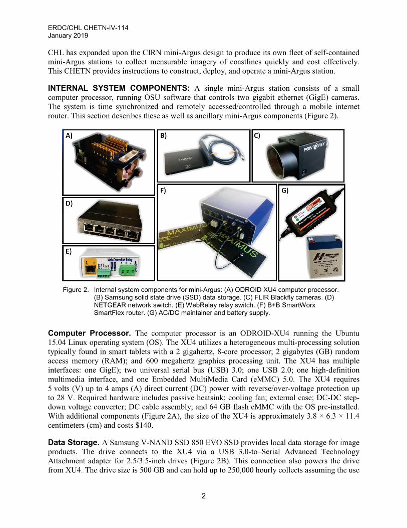
INTERNAL SYSTEM COMPONENTS: A single mini-Argus station consists of a small computer processor, running OSU software that controls two gigabit ethernet (GigE) cameras. The system is time synchronized and remotely accessed/controlled through a mobile internet router. This section describes these as well as ancillary mini-Argus components (Figure 2).
Figure 2. Internal system components for mini-Argus: (A) ODROID XU4 computer processor.
Computer Processor. The computer processor is an ODROID-XU4 running the Ubuntu 15.04 Linux operating system (OS). The XU4 utilizes a heterogeneous multi-processing solution typically found in smart tablets with a 2 gigahertz, 8-core processor; 2 gigabytes (GB) random access memory (RAM); and 600 megahertz graphics processing unit. The XU4 has multiple interfaces: one GigE); two universal serial bus (USB) 3.0; one USB 2.0; one high-definition multimedia interface, and one Embedded MultiMedia Card (eMMC) 5.0. The XU4 requires 5 volts (V) up to 4 amps (A) direct current (DC) power with reverse/over-voltage protection up to 28 V. Required hardware includes passive heatsink; cooling fan; external case; DC-DC step-down voltage converter; DC cable assembly; and 64 GB flash eMMC with the OS pre-installed. With additional components (Figure 2A), the size of the XU4 is approximately 3.8 × 6.3 × 11.4 centimeters (cm) and costs $140.
Data Storage. A Samsung V-NAND SSD 850 EVO SSD provides local data storage for image products. The drive connects to the XU4 via a USB 3.0-to–Serial Advanced Technology Attachment adapter for 2.5/3.5-inch drives (Figure 2B). This connection also powers the drive from XU4. The drive size is 500 GB and can hold up to 250,000 hourly collects assuming the use
ERDC/CHL CHETN-IV-114 January 2019
3
of cameras specified in this report and storing only imagery (no pixel time series collects for bathymetry estimation). The size of the drive is 70 ×100 × 5 millimeters (mm) and costs $170; various sizes of USB-to-SATA adapters can be purchased for approximately $35.
HOTM v. 3.2 Software. Developed by Dr. John Stanley at OSU, HOTM is a collection of Perl and C++ scripts for camera control and Argus imagery product production. HOTM is freely available on the Argus Database (ArgusDB); links to the ArgusDB and documentation of Argus products naming conventions can be found at the CIRN GitHub Repository. HOTM is unique and advantageous because it computes full-frame image statistical products in near real time. Additionally, it can save videos of desired pixels rather than full frames to significantly reduce file sizes for long-time duration collections. HOTM utilizes the free FlyCapture2 Software Development Kit (SDK) by PointGrey (now FILR) to interface and control cameras. Thus, the XU4 must have FlyCapture installed, and selected cameras must utilize this SDK interface.
Cameras. Each mini-Argus station operates up to two Point Grey (FLIR) Blackfly color cameras (Figure 2C; model number: BFLY-PGE-50H5C-C). The cameras have a 5.0 megapixel global shutter, GigE interface, 2448 × 2048 pixel resolution, and can record up to 7.5 frames per second. The cameras nominally require 12 V and can consume up to 2.5 watts (W) via power over ethernet or a DC cable assembly (the latter selected). The cameras are 29 × 29 × 30 mm in size and cost $995 each. Low distortion, 8 mm c-mount lenses approximately add $300 cost and double the length.
Network Switch. A Netgear GS105E Prosafe Plus 5-port GigE network switch provides inter-connectivity between the XU4, cameras, mobile internet router, and relay switch (Figure 2D). The network switch also provides a direct physical connection for laptop secure shell (SSH) and hypertext transfer protocol (HTTP) access. The network switch has jumbo frame support, a requirement for camera operation. The switch is 10 × 9 × 1.5 cm, requires 12 V DC external input (2.5 W maximum), and costs $50.
Web-enabled Relay Switch. A ControlByWeb WebRelay switch allows remote power cycling of mini-Argus station components (Model No: X-WR-1R12-1I-I; Figure 2E). Power cycling occurs via manual control over HTTP and automated response to trigger input voltage. The WebRelay cycles power to the XU4, cameras, and network switch. The router and relay switch receives constant power, so remote connectivity is not lost. The relay switch is 9.5 × 7.5 × 3.5 cm, requires/controls 9–28 V DC, outputs 5 V, can accept 4–26 V trigger input, and costs $104.
Mobile Cellular Router. A B+B SmartWorx SmartFlex Industrial LTE router provides remote access to the mini-Argus components (Part No: SR30310125-SWH; Figure 2E). Additional purchases include a subscriber identification module (SIM) card associated with a 4G mobile data plan with a fixed internet protocol (IP) address; and the router’s MAC address. The router has SSH, HTTP, hypertext transfer protocol secure (HTTPS), and SSH file transfer protocol firewall protection to restrict IP access for security. The router has a programmable binary voltage switch (10–60 V) that is utilized for the WebRelay trigger input. The chosen model has an additional three GigE interfaces (five total); such ports bypass the network switch in case of power cycling to provide continuous connection between router, relay switch, and local/remote HTTP access. No ports have jumbo frame support, however; thus, live camera feeds can only be accessed via a physical connection to the network switch and not remotely. Chosen for small
ERDC/CHL CHETN-IV-114 January 2019
4
form factor, two Taoglass Maximus FXUB66 Ultra Wide Band Flex Antennas with male SMA connectors provide connectivity. The router and antennas are 12 × 5.5 × 9 cm and cost $650 and $8, respectively.
Power Supply. The mini-Argus system is powered by typical household 120–240 alternating current (AC) power. A MotoPower Automatic Battery Maintainer (Model MP0206) converts AC to 12 V 1.5A DC output and maintains charge of a lead acid battery (Figure 2F). The PowerSonic 6 amp-hour, 12 V lead acid rechargeable battery (Model PSH-1255F2-FR) provides an uninterrupted power supply in case of power flickers and short-term outages. For a given hour, the system nominally draws 1.3 A for 45 minutes; however, during data collection and processing (15 minutes), draw can reach up to 1.7 A. The battery provides approximately 4 hours of operation if not maintained. Once fully drained, however, the battery must be replaced and charged. The maintainer and battery were chosen for their low cost ($25 and $28) and form factor (13 × 4 × 7 and 7 × 10 × 9 cm); however, larger batteries can provide longer operation.
EXTERNAL SYSTEM COMPONENTS: The mini-Argus structure consists of watertight enclosures clamped to an 8-foot fiberglass pole (Figure 3A).With the exception of an AC extension and grounding cable, the system is self-contained and can be transported as one piece, fitting easily in a mid-size sport-utility vehicle.
Figure 3. External mini-Argus components: (A) Camera enclosures. (B) Fiberglass enclosures with
heatsink in red. Inside: (C) Networked components (top) and power supply (bottom). (D) Watertight cable glands and Cat6 GigE ports. (E) Example mounting points.
Enclosures. The internal components reside in watertight enclosures with a minimum rating of Ingress Protection Rating of 66 (IP66). Pelco EH3508 camera enclosures with EM1109 adjustable pole mounts house each camera. The Pelco enclosures/mounts are approximately 8–15 inches in length and cost $110–$112, respectively. Stahlin fiberglass enclosures house the networked (top) and power supply (bottom) components (Figure 3B-C; Part No: CL1109W and CL907W, respectively).The top/bottom are 27 × 22 × 15–22 × 17 × 12 cm and cost $230–$220 with mounting panels. The top cover is punctured; it is filled with a passive heatsink bolted to an aluminum plate and sealed with marine epoxy (red circle, Figure 3B). Cable glands provide watertight cable entry between components, and Cat6 GigE watertight ports provide local network access without removing the cover (Figure 3D).
Structure. The enclosures are bolted to marine-grade plywood that is U-bolted to the fiberglass pole (Figure 3D). The fiberglass pole is hose-clamped to existing infrastructure such as deck
ERDC/CHL CHETN-IV-114 January 2019
5
railings; clamps are placed as high as possible to resist pole deflection and camera motion due to wind. The fiberglass pole has a large 0.32/6.4 cm inner/outer diameter to further resist bending moment and costs $45.
Lightning Protection. The mini-Argus system has fiberglass poles to reduce the chance of lightning strike. However, since some components are metal, further protection is added with a grounding cable that connects the power supply to a grounding rod staked into the ground. Further voltage/current protection is in the system wiring.
SYSTEM WIRING: The mini-Argus components are interconnected via power and a GigE network. In both Stahlin enclosures, components are mounted directly to aluminum back plates or via bolted DIN1 rail. Terminal blocks and DINnectors provide electrical connections. Figure 4 presents wiring diagrams and outlines key features.
Power Protection. In addition to the grounding cable; gas discharge tubes, diodes, and current fuses provide protection against lightning and power surges in Figure 4A. Additional protection is provided by the battery maintainer.
Power Distribution. Power distribution occurs via two channels. The blue DINnectors provide continuous 12 V power to the router and WebRelay (Figure 4B).The red DINnectors provide 12 V power through the WebRelay that can be switched on/off manually or via a trigger voltage (Figure 4C). The WebRelay constantly outputs 5 V; this voltage travels through the router binary output switch and back to the WebRelay as the trigger input. The router is programmed to switch the trigger voltage at specific times to engage the WebRelay and cycle power. The two switches provide two means of power cycling: on-demand (WebRelay) and scheduled (router).
GigE Network. Cat6 ethernet cables connect the cameras, router, WebRelay, XU4, and network switch (Figure 4B–C). Right-angled cables provide connectivity with a small form factor for connections within the enclosure (Figure 3C). Two local connections from outside the box provide physical access to the network switch (I) and router (II). Connection I allows for a live camera feed through the network switch that supports jumbo packets. Connection II bypasses the network switch though the router and is for cycling power via the WebRelay/.
1 Deutsches Institut fur Normung (German Institute for Standardization)
ERDC/CHL CHETN-IV-114 January 2019
6
Figure 4. Mini-Argus wiring schematic. A) Power supply box. B)
Networked box, continuously powered components. C) Networked box, switched components.
NETWORK CONNECTIVITY: Figure 5 is a network diagram of the mini-Argus system. A local area network (LAN) interconnects the internal components and field laptop; each component is specified a unique fixed IP. The LAN is accessed remotely via the SIM card IP. Components requiring remote access are assigned public/private port numbers via the router IPv4 NAT (Network Address Translation) configuration. The router firewall is specified to restrict access to specified IPs for security. The WebRelay, router, and XU4 are all password protected.
ERDC/CHL CHETN-IV-114 January 2019
7
Figure 5. Mini-Argus network schematic and IPv4 NAT configuration.
SYSTEM OPERATIONS: The following section outlines procedures and scripts necessary to produce mini-Argus image products automatically and on-demand.
HOTM: For successful operation, HOTM must be installed in the user home directory (FlyCapture SDK is included). The HOTM manual is accessible through the ArgusDB. Table 1 outlines the minimum number of HOTM files and variables that need to be altered.
Table 1. HOTM v. 3.2 file modifications necessary for Mini-Argus operation. File Name Description Variable Modifications
cameraMapping Assigns camera number (label) to a camera serial number
Camera number (only 1-9 possible)and camera serial number
cameraData Specifies camera model parameters Proprietary modifications; modification only if Blackfly model PGE-50H5Cnot used
cam0x.startup Specifies framerate, white balance, shutter exposure, and gain for all cameras
frame_rate in Hz; white_balance_r; white_balance_b; shutter in seconds; gain
cdisk Provides station parameters sitename Station Name
camerasonbus Number of cameras at station
move_data Specifies directory to store image products SSD drive as desired directory
pix Specifies pixels to extract for timeseries Two columns of U,V coordinates
After modification of scripts in Table 1, HOTM perl scripts can be executed either via the command line (on-demand) or crontab (scheduled). Table 2 lists the commands and necessary input. Input is labeled as A, B, C, etc., and defined. The FlyCapture 2 graphical user interface provides a live feed without scripts in Tables 1–2. This feature is useful for camera extrinsic/intrinsic calibration; however, it can only occur with a physical Cat6 connection via the network switch.
ERDC/CHL CHETN-IV-114 January 2019
8
Table 2. HOTM v. 3.2 scripts necessary for Mini-Argus operation. Script Execution Description Input (A,B,C…) startup.pl A Initializes camera
A: Camera number (label) as defined in cameraMapping. Can be more than one camera specified, i.e. 1 2
shutdown.pl A Shuts down camera
statusCheck A Pings camera and waits for response
doCamAndSend A B C D E
Takes imagery, produces Argus products, moves products to directory specified by move_data
B: Number of frames. C: Frames to skip (alter framerate) D: When to start capture in sec, or top of minute, hour E: Directory of pixel file for timeseries collect (optional)
Camera Scheduling. The crontab schedules a series of HOTM commands to collect and produce Argus imagery every hour. Individual cronjobs are formatted as m h D M Y Command. The letters m h D M Y are the minute, hour, day, month, year timestamp to start the cronjob. The asterisk (*) denotes any value. The following is an example crontab for an hourly mini-Argus collect:
Time Synchronization. For accurate synchronization between mini-Argus stations and other instrumentation, each mini-Argus XU4 synchronizes with selected Network Time Protocol (NTP) servers. To accomplish this, the router synchronizes with 0.pool.ntp.org (primary) and 2.centos.pool.ntp.org (secondary). Local NTP service is activated on the router. Via the ntp.conf file on the XU4, the local router IP is set as the preferred server: server 192.168.1.1 prefer.
Remote Access. The XU4 operates as a traditional personal computer with attached mouse, keyboard, and monitor. However, once constructed in full, the XU4 is only accessible via terminal. The MobaXTerm software facilitates this connection for Windows machines and is particularly useful for field laptops that require Windows for other software.
Power Cycling. The WebRelay cycles power to the network switch, XU4, and cameras. This can be done manually through the HTTP port; the WebRelay has a hypertext markup language interface to set switch status and change setting parameters. To cycle power automatically, the WebRelay is set to match the switch status with the trigger input. The trigger input (the router’s binary output out0) is programmed to turn on/off through the router scripts/crontab accessed through the router settings (Port 8084). The following commands turn off the trigger input at the 40 of every hour and turn on the trigger input at the 45 of daylight hours 10-22 Greenwich Mean Time.
echo “40 * * * * root /usr/bin/io set out0 0” > /etc/crontab echo “45 10-22 * * * root /usr/bin/io set out0 1” > /etc/crontab service cron start
ERDC/CHL CHETN-IV-114 January 2019
9
PILOT DEPLOYMENT: In early 2018, a pilot field study evaluated five mini-Argus stations deployed at the CHL-FRF and surrounding areas. This section will provide preliminary results for one location, Pelican Perch (PP), Kitty Hawk, NC. PP is a small house onshore of the beach dune; there is a second-story deck and outdoor electrical access (Figure 6). There are two stations, each with two cameras. Imagery from the four cameras spanned approximately 180o. To determine camera extrinsics, the stations recorded imagery of surveyed ground control points (GCPs) (Figure 6). Prior to installation, the camera/lens/enclosure combinations were intrinsically calibrated. Information for intrinsic/extrinsic calibrations, camera placement, and georectification is on the CIRN repository.
Figure 6. PP deployment field of view (FOV).Top: PP site. Bottom: Imagery from Cameras 1-
4 with GCPs visible.Camera orientations are north-northwest, north-northeast, east, and east-southeast, respectively.
RESULTS AND DISCUSSION: Deployments ran successfully from January–May 2018. Figure 7 shows an example geo-rectified timex-image from the PP deployment; the root-mean-square error for georectification is 1.6 m from GCP ground truth. The spatial coverage was approximately half as compared to tower Argus products (Figure 1B), due to a lower elevation (11 m vs. 43 m).
Figure 7. Geo-rectified time averaged (10 minute) imagery from mini-Argus stations at PP.
ERDC/CHL CHETN-IV-114 January 2019
10
There were intermittencies in the data due to the (1) external AC power supply and (2) camera visibility. Outdoor AC power outlets on roofs, independent of the mini-Argus system, infrequently tripped due to moisture. These ground faults could not be reset remotely and required a site visit. The systems themselves provided a high rate of data return; the stations ran continuously through rain and snow storms when AC power was available. Camera enclosures, however, became obscured by salt, snow/ice, and rain droplets. High winds also induced slight camera movement.
SUMMARY AND FUTURE DEVELOPMENT: This CHETN provides an instruction manual for the construction and operation of a low-cost easily deployable mini-Argus station. The autonomous system provides rapid and mensurable imagery suitable for monitoring nearshore environments. A pilot deployment demonstrated reliable data return, even during storm events. Future improvements to reduce data intermittency include climate controlled camera enclosures, guywires for wind loads, and additional power redundancy. Significance of deployment height on data quality and image stabilization will also be studied for system development. Future work will analyze deployment data and potential USACE applications such as beach project monitoring.
ADDITIONAL INFORMATION: This CHETN was prepared as part of the USACE Coastal and Oceans Data Systems (CODS) Program by Dr. Brittany Bruder, Kent Hathaway, and Dr. Katherine Brodie, ERDC-CHL, Duck, NC. Questions pertaining to this CHETN may be directed to Dr. Brittany Bruder ([email protected]) or to the USACE CODS Program Manager, Dr. Jeffrey Waters ([email protected]). Additional information regarding CODS may be obtained from the CODS web site http://cods.usace.army.mil/.
This ERDC/CHL CHETN-IV-114 should be cited as follows:
Bruder, B. L., K. J. Hathaway, and K. L. Brodie. 2019. Design and Deployment of Mini-Argus Systems for Rapid Coastal Imaging. ERDC/CHL CHETN-IV-114. Vicksburg, MS: U.S. Army Engineer Research and Development Center. http://dx.doi.org/10.21079/11681/31463
REFERENCES
Holman, R. A., and J. Stanley. 2007. The history and technical capabilities of Argus. Coastal Engineering 54(6–7):477–491.
Holman, Rob, Nathaniel Plant, and Todd Holland. 2013. cBathy: A robust algorithm for estimating nearshore bathymetry. Journal Of Geophysical Research: Oceans 118(5):2595–2609.
NOTE: The contents of this technical note are not to be used for advertising, publication, or promotional purposes. Citation of trade names does not constitute an official
endorsement or approval of the use of such products.


![[A]go.vsb.bc.ca/schools/pointgrey/departments/English/Glossary Of... · Although the surface story may ... sometimes presented for its own sake or for its interest in relation to](https://static.documents.pub/doc/80x56/5ae9eeb77f8b9ac3618d0c4d/agovsbbccaschoolspointgreydepartmentsenglishglossary-ofalthough-the.jpg)


