23
eRHIC Accelerator Design V. Ptitsyn for the eRHIC design team
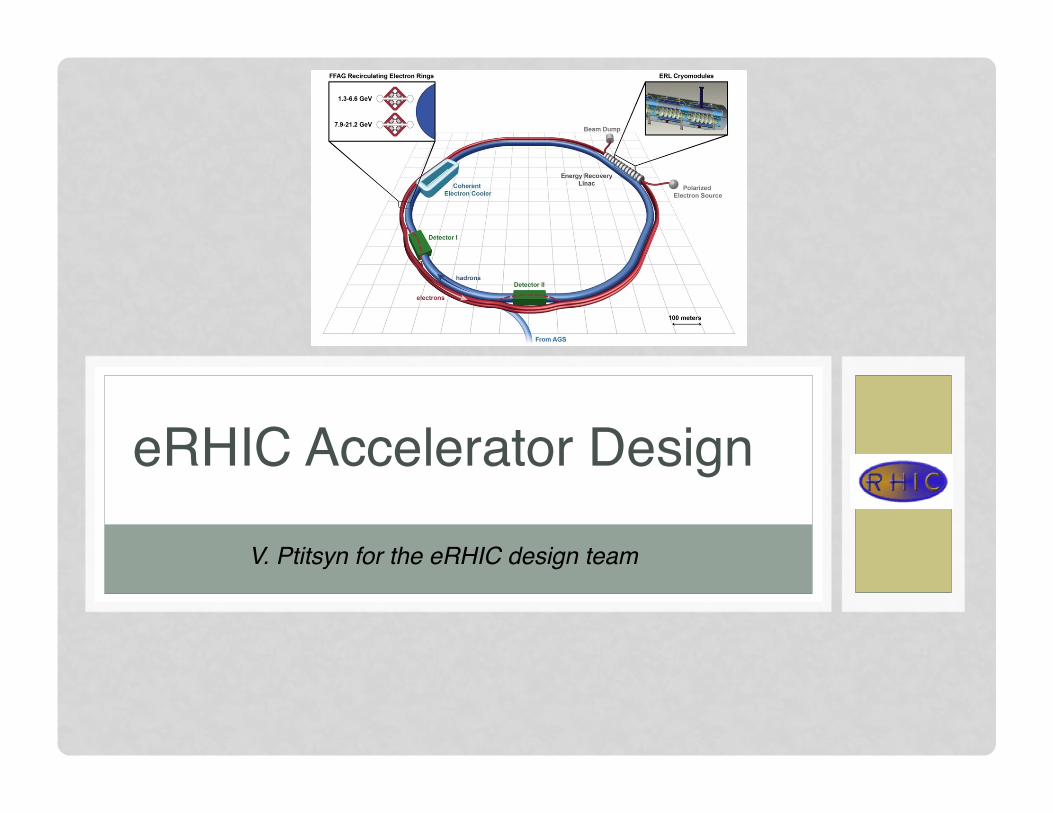
eRHIC Accelerator Design
V. Ptitsyn for the eRHIC design team!
2
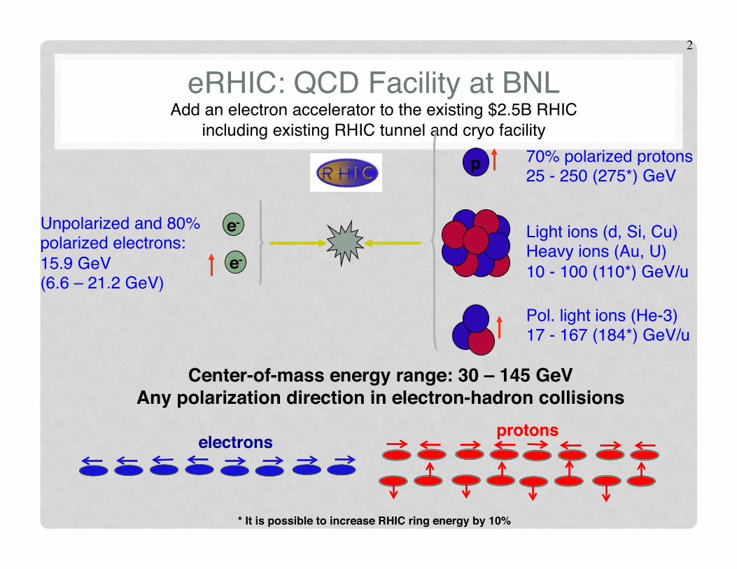
eRHIC: QCD Facility at BNL Add an electron accelerator to the existing $2.5B RHIC
including existing RHIC tunnel and cryo facility"
e-!
p!
Unpolarized and 80% polarized electrons:15.9 GeV"(6.6 – 21.2 GeV)"
Pol. light ions (He-3) 17 - 167 (184*) GeV/u"
Light ions (d, Si, Cu)"Heavy ions (Au, U)"10 - 100 (110*) GeV/u"
70% polarized protons "25 - 250 (275*) GeV"
Center-of-mass energy range: 30 – 145 GeV!Any polarization direction in electron-hadron collisions!
e-!
protons!electrons!
* It is possible to increase RHIC ring energy by 10%!!
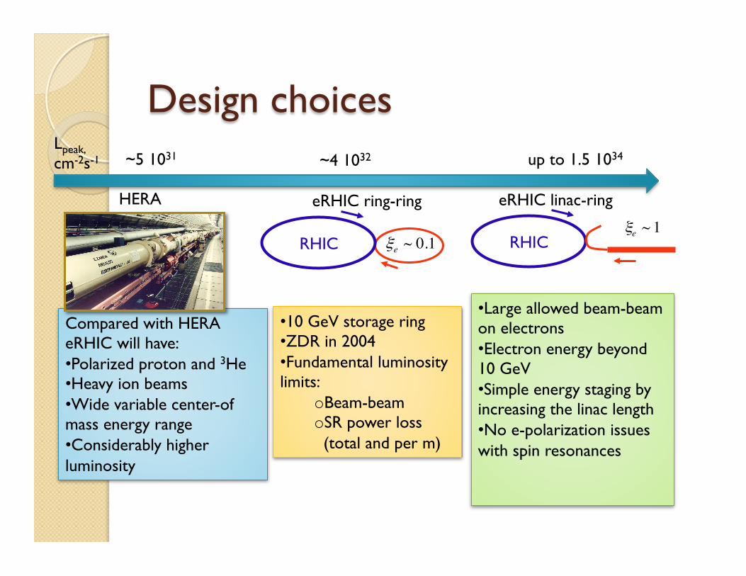
Design choices
Compared with HERA eRHIC will have: • Polarized proton and 3He • Heavy ion beams • Wide variable center-of mass energy range • Considerably higher luminosity
Lpeak, cm-2s-1 ~5 1031
HERA
• 10 GeV storage ring • ZDR in 2004 • Fundamental luminosity limits:
o Beam-beam o SR power loss (total and per m)
RHIC
~4 1032
eRHIC ring-ring
€
ξe ~ 0.1
• Large allowed beam-beam on electrons • Electron energy beyond 10 GeV • Simple energy staging by increasing the linac length • No e-polarization issues with spin resonances
RHIC
up to 1.5 1034
eRHIC linac-ring
€
ξe ~ 1
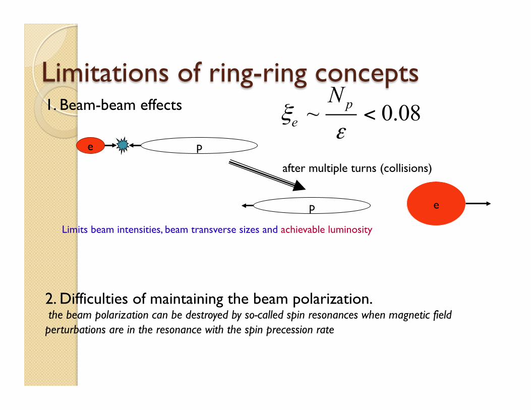
Limitations of ring-ring concepts 1. Beam-beam effects
Limits beam intensities, beam transverse sizes and achievable luminosity
e p
~ 0.08pe
Nξ
ε<
e p
after multiple turns (collisions)
2. Difficulties of maintaining the beam polarization. the beam polarization can be destroyed by so-called spin resonances when magnetic field perturbations are in the resonance with the spin precession rate

5
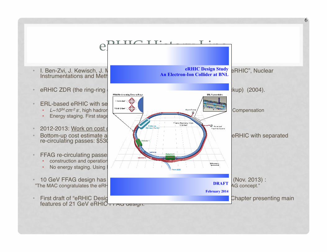
eRHIC History Line • I. Ben-Zvi, J. Kewisch, J. Murphy, S.Peggs, “Accelerator Physics Issues in eRHIC”, Nuclear
Instrumentations and Methods in Physics Research A 463 (2001), p.94. "
• eRHIC ZDR (the ring-ring design with L~1032 cm-2 s-1; ERL linac-ring as backup) (2004)."
• ERL-based eRHIC with separated re-circulating passes"• L~1034 cm-2 s-, high hadron beam intensity, upgrades in hadron ring, Space Charge Compensation"• Energy staging. First stage eRHIC: 4-5 GeV electron machine.""
• 2012-2013: Work on cost optimized machine design."• Bottom-up cost estimate and optimization: minimal cost first stage (5 GeV) eRHIC with separated
re-circulating passes: $530 mln. (detector(s) not included)."
• FFAG re-circulating passes + permanent magnets"• construction and operational cost savings"• No energy staging. Using FFAG passes widens the energy reach at moderate cost."
• 10 GeV FFAG design has been evaluated by Machine Advisory Committee (Nov. 2013) :" ”The MAC congratulates the eRHIC design team for its ingenious and novel use of the FFAG concept.”""• First draft of “eRHIC Design Study” report includes the Accelerator Design Chapter presenting main
features of 21 GeV eRHIC FFAG design."
6
eRHIC History Line • I. Ben-Zvi, J. Kewisch, J. Murphy, S.Peggs, “Accelerator Physics Issues in eRHIC”, Nuclear
Instrumentations and Methods in Physics Research A 463 (2001), p.94. "
• eRHIC ZDR (the ring-ring design with L~1032 cm-2 s-1; ERL linac-ring as backup) (2004)."
• ERL-based eRHIC with separated re-circulating passes"• L~1034 cm-2 s-, high hadron beam intensity, upgrades in hadron ring, Space Charge Compensation"• Energy staging. First stage eRHIC: 4-5 GeV electron machine.""
• 2012-2013: Work on cost optimized machine design."• Bottom-up cost estimate and optimization: minimal cost first stage (5 GeV) eRHIC with separated
re-circulating passes: $530 mln. (detector(s) not included)."
• FFAG re-circulating passes + permanent magnets"• construction and operational cost savings"• No energy staging. Using FFAG passes widens the energy reach at moderate cost."
• 10 GeV FFAG design has been evaluated by Machine Advisory Committee (Nov. 2013) :" ”The MAC congratulates the eRHIC design team for its ingenious and novel use of the FFAG concept.”""• First draft of “eRHIC Design Study” report includes the Accelerator Design Chapter presenting main
features of 21 GeV eRHIC FFAG design." 1
eRHIC Design Study An Electron-Ion Collider at BNL
DRAFT
February 2014

7
Cost-Effective eRHIC Design"² Up to 21.2 GeV electron beam accelerated with Energy Recovery Linac (ERL) inside existing RHIC tunnel
collides with existing 250 GeV polarized protons and 100 GeV/n HI RHIC beams"² Single collision of each electron bunch allows for large disruption, giving high luminosity and full electron
polarization transparency"² Use 2 FFAG magnet strings in RHIC tunnel to transport up to 16 beams"² Considered permanent magnet design for FFAG lattice magnets "² Cool hadron beam 10-fold in all directions using coherent electron cooling (CeC) at reduced intensity of
hadron beam "² IR design with β*= 5 cm using SC magnet technology and crab-crossing scheme"² Average polarized electron current of 50 mA "
Design provides full luminosity (> 1033 cm-2 s-1) up to 15.9 GeV and reduced luminosity up to 21.2 GeV 1.32 GeV
8
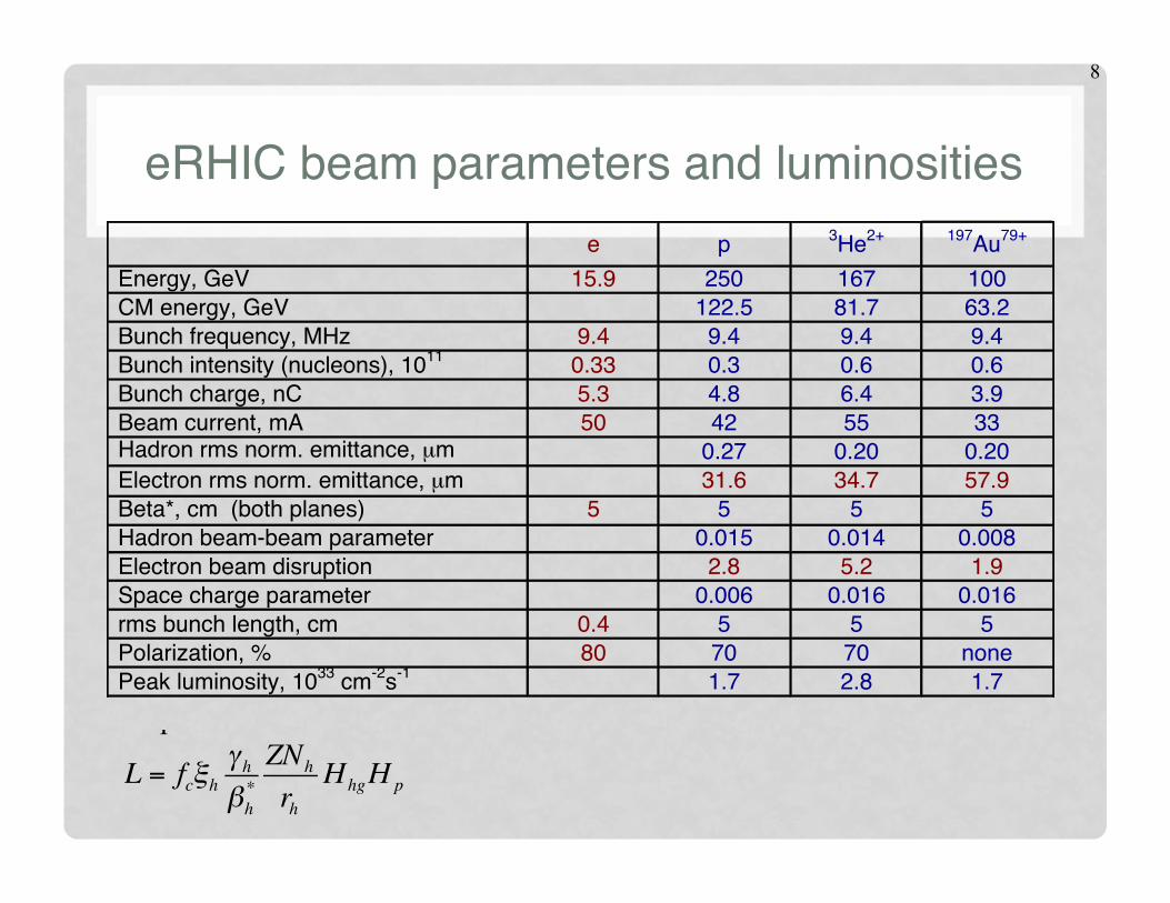
eRHIC beam parameters and luminosities" e p 3He2+ 197Au79+
Energy, GeV 15.9 250 167 100 CM energy, GeV 122.5 81.7 63.2 Bunch frequency, MHz 9.4 9.4 9.4 9.4 Bunch intensity (nucleons), 1011 0.33 0.3 0.6 0.6 Bunch charge, nC 5.3 4.8 6.4 3.9 Beam current, mA 50 42 55 33 Hadron rms norm. emittance, µm 0.27 0.20 0.20 Electron rms norm. emittance, µm 31.6 34.7 57.9 Beta*, cm (both planes) 5 5 5 5 Hadron beam-beam parameter 0.015 0.014 0.008 Electron beam disruption 2.8 5.2 1.9 Space charge parameter 0.006 0.016 0.016 rms bunch length, cm 0.4 5 5 5 Polarization, % 80 70 70 none Peak luminosity, 1033 cm-2s-1 1.7 2.8 1.7
3
strong focusing to achieve the β*=5 cm for both beams. The electron and hadron beams are brought into the collision with a 10 mrad crossing angle. Crab cavities are employed to prevent loss of luminosity due to the crossing angle.
The present RHIC accelerator uses superconducting magnets to circulate hadron beams in two rings of 3834 m circumference. The wide energy reach of RHIC provides a natural opportunity to operate eRHIC over a wide range of center-of-mass collision energies. Existing proven accelerator technologies, exploited in RHIC and its injectors to produce and preserve proton beam polarization, will provide the highly polarized proton beam required for the eRHIC experiments. Modifications of the present RHIC machine for the eRHIC era include new quadrupole and dipole magnets in two interaction regions with experimental detectors, a hadron delay line for electron-hadron frequency matching, and additional Siberian Snakes for acceleration of polarized 3He+2. Also, a cooling device will be added with the purpose of producing small transverse and longitudinal beam emittances.
3.1.2 Design Beam Parameters and Luminosities Based on the fact that electrons, accelerated by the linear accelerator, collide with the
protons (or ions) accelerated and stored in the circular machine, the eRHIC collision scheme is called the “linac-ring” scheme. This scheme has been chosen for eRHIC because of several clear advantages it brings in luminosity and electron polarization. On the luminosity side the “linac-ring” scheme overcomes one of the fundamental luminosity limitations of the “ring-ring” scheme from circulating electron beam quality deterioration caused by many repeating beam-beam interactions. Unlike the electron beam circulating in a storage ring, the electron beam from a linac passes through the collision point(s) only once. Hence, a beam-beam interaction of much higher strength can be allowed, paving the way to higher luminosity. The luminosity of the “linac-ring” scheme can be written as a function of the hadron beam parameters:
,
where is the hadron classical radius, ξh is the hadron beam-beam parameter, is the hadron beta-function at the interaction point, Nh is the hadron bunch intensity, γh is the hadron relativistic factor and Z is the hadron charge. fc is the collision frequency, which is the same as the bunch repetition rate.
The geometric loss factor Hhg arises from luminosity loss due to the hour-glass effect and the crossing angle. With a 10 mrad crossing angle at the eRHIC collision points, the crab-crossing technique has to be employed to prevent luminosity loss.
The Hp parameter represents the luminosity enhancement resulting from the pinching of the electron beam size at the collision point caused by the hadron beam focusing force.
The design luminosity and choice of beam parameters are influenced by both physical limits and practical considerations. Some of these limitations, such as the maximum limits for the hadron beam-beam and space-charge parameters for hadrons come from operational and experimental observations at RHIC or other hadron colliders. Others, like the choice of β* or the polarized electron beam current, are defined by the limits of accelerator technology. Considerations of the operational cost of the machine limit the electron beam power loss caused by synchrotron radiation. The major limits assumed for the beam and accelerator parameters are:
• Polarized electron average current: Ie ≤ 50 mA • Minimum β* = 5 cm (for both electrons and hadrons) • Hadron space-charge tune shift: ΔQsp ≤ 0.035
L = fcξhγhβh*ZNh
rhHhgH p
rh = Z2e2 /Mc2 βh
*

9
eRHIC beam parameters and luminosities" e p 3He2+ 197Au79+
Energy, GeV 15.9 250 167 100 CM energy, GeV 122.5 81.7 63.2 Bunch frequency, MHz 9.4 9.4 9.4 9.4 Bunch intensity (nucleons), 1011 0.33 0.3 0.6 0.6 Bunch charge, nC 5.3 4.8 6.4 3.9 Beam current, mA 50 42 55 33 Hadron rms norm. emittance, µm 0.27 0.20 0.20 Electron rms norm. emittance, µm 31.6 34.7 57.9 Beta*, cm (both planes) 5 5 5 5 Hadron beam-beam parameter 0.015 0.014 0.008 Electron beam disruption 2.8 5.2 1.9 Space charge parameter 0.006 0.016 0.016 rms bunch length, cm 0.4 5 5 5 Polarization, % 80 70 70 none Peak luminosity, 1033 cm-2s-1 1.7 2.8 1.7
Future luminosity upgrade!The proton beam intensity is only at ~15% of present level. "Open path to the moderate cost luminosity upgrade the future by increasing the hadron beam intensity (by an order of magnitude) and related hadron ring improvements: "copper coating of beam pipe, beam diagnostics upgrade, RF system upgrade!" Luminosity above 1034 cm-2 s-1 can be reached! "
3
strong focusing to achieve the β*=5 cm for both beams. The electron and hadron beams are brought into the collision with a 10 mrad crossing angle. Crab cavities are employed to prevent loss of luminosity due to the crossing angle.
The present RHIC accelerator uses superconducting magnets to circulate hadron beams in two rings of 3834 m circumference. The wide energy reach of RHIC provides a natural opportunity to operate eRHIC over a wide range of center-of-mass collision energies. Existing proven accelerator technologies, exploited in RHIC and its injectors to produce and preserve proton beam polarization, will provide the highly polarized proton beam required for the eRHIC experiments. Modifications of the present RHIC machine for the eRHIC era include new quadrupole and dipole magnets in two interaction regions with experimental detectors, a hadron delay line for electron-hadron frequency matching, and additional Siberian Snakes for acceleration of polarized 3He+2. Also, a cooling device will be added with the purpose of producing small transverse and longitudinal beam emittances.
3.1.2 Design Beam Parameters and Luminosities Based on the fact that electrons, accelerated by the linear accelerator, collide with the
protons (or ions) accelerated and stored in the circular machine, the eRHIC collision scheme is called the “linac-ring” scheme. This scheme has been chosen for eRHIC because of several clear advantages it brings in luminosity and electron polarization. On the luminosity side the “linac-ring” scheme overcomes one of the fundamental luminosity limitations of the “ring-ring” scheme from circulating electron beam quality deterioration caused by many repeating beam-beam interactions. Unlike the electron beam circulating in a storage ring, the electron beam from a linac passes through the collision point(s) only once. Hence, a beam-beam interaction of much higher strength can be allowed, paving the way to higher luminosity. The luminosity of the “linac-ring” scheme can be written as a function of the hadron beam parameters:
,
where is the hadron classical radius, ξh is the hadron beam-beam parameter, is the hadron beta-function at the interaction point, Nh is the hadron bunch intensity, γh is the hadron relativistic factor and Z is the hadron charge. fc is the collision frequency, which is the same as the bunch repetition rate.
The geometric loss factor Hhg arises from luminosity loss due to the hour-glass effect and the crossing angle. With a 10 mrad crossing angle at the eRHIC collision points, the crab-crossing technique has to be employed to prevent luminosity loss.
The Hp parameter represents the luminosity enhancement resulting from the pinching of the electron beam size at the collision point caused by the hadron beam focusing force.
The design luminosity and choice of beam parameters are influenced by both physical limits and practical considerations. Some of these limitations, such as the maximum limits for the hadron beam-beam and space-charge parameters for hadrons come from operational and experimental observations at RHIC or other hadron colliders. Others, like the choice of β* or the polarized electron beam current, are defined by the limits of accelerator technology. Considerations of the operational cost of the machine limit the electron beam power loss caused by synchrotron radiation. The major limits assumed for the beam and accelerator parameters are:
• Polarized electron average current: Ie ≤ 50 mA • Minimum β* = 5 cm (for both electrons and hadrons) • Hadron space-charge tune shift: ΔQsp ≤ 0.035
L = fcξhγhβh*ZNh
rhHhgH p
rh = Z2e2 /Mc2 βh
*

10
Luminosity versus Beam Energy"
• Luminosity versus hadron beam energy"• For 15.9 GeV electron energy or
less"• Limited by hadron beam-beam
parameter above 100 GeV and space charge below 100 GeV"
• Luminosity versus electron beam energy"• Limited by maximum SR power of
12 MW above 15.9 GeV"
0"0.2"0.4"0.6"0.8"1"
1.2"1.4"1.6"1.8"
10" 12" 14" 16" 18" 20" 22"
Luminosity,++10
33+cm
02+ s01+
Electron+energy,+GeV+
Defined by PSR = 12 MW
0"
0.2"
0.4"
0.6"
0.8"
1"
1.2"
1.4"
1.6"
1.8"
0" 50" 100" 150" 200" 250" 300"
Luminosity
,+103
3+cm
02s01
+
Proton+energy,+GeV+
Defined by ξp = 0.015
Defined by ΔQsp = 0.035
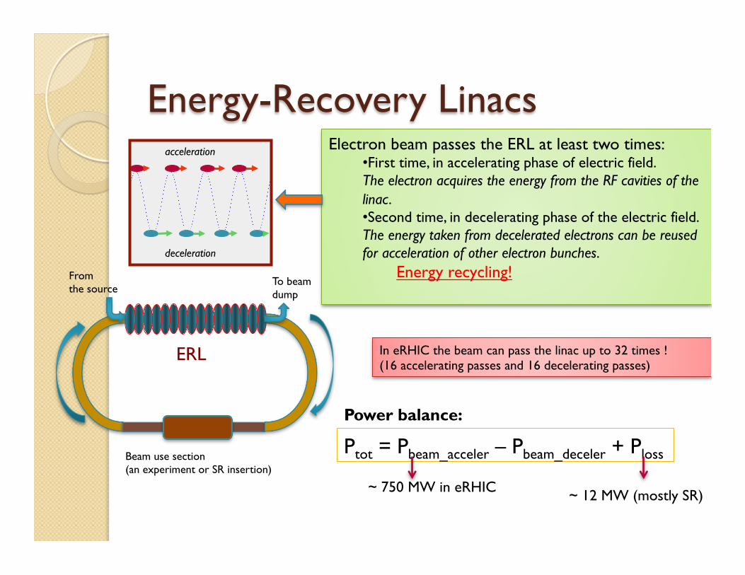
Energy-Recovery Linacs
ERL
Electron beam passes the ERL at least two times: • First time, in accelerating phase of electric field. The electron acquires the energy from the RF cavities of the linac. • Second time, in decelerating phase of the electric field. The energy taken from decelerated electrons can be reused for acceleration of other electron bunches.
Energy recycling!
Beam use section (an experiment or SR insertion)
In eRHIC the beam can pass the linac up to 32 times ! (16 accelerating passes and 16 decelerating passes)
Ptot = Pbeam_acceler – Pbeam_deceler + Ploss
Power balance:
From the source
To beam dump
acceleration
deceleration
~ 750 MW in eRHIC ~ 12 MW (mostly SR)
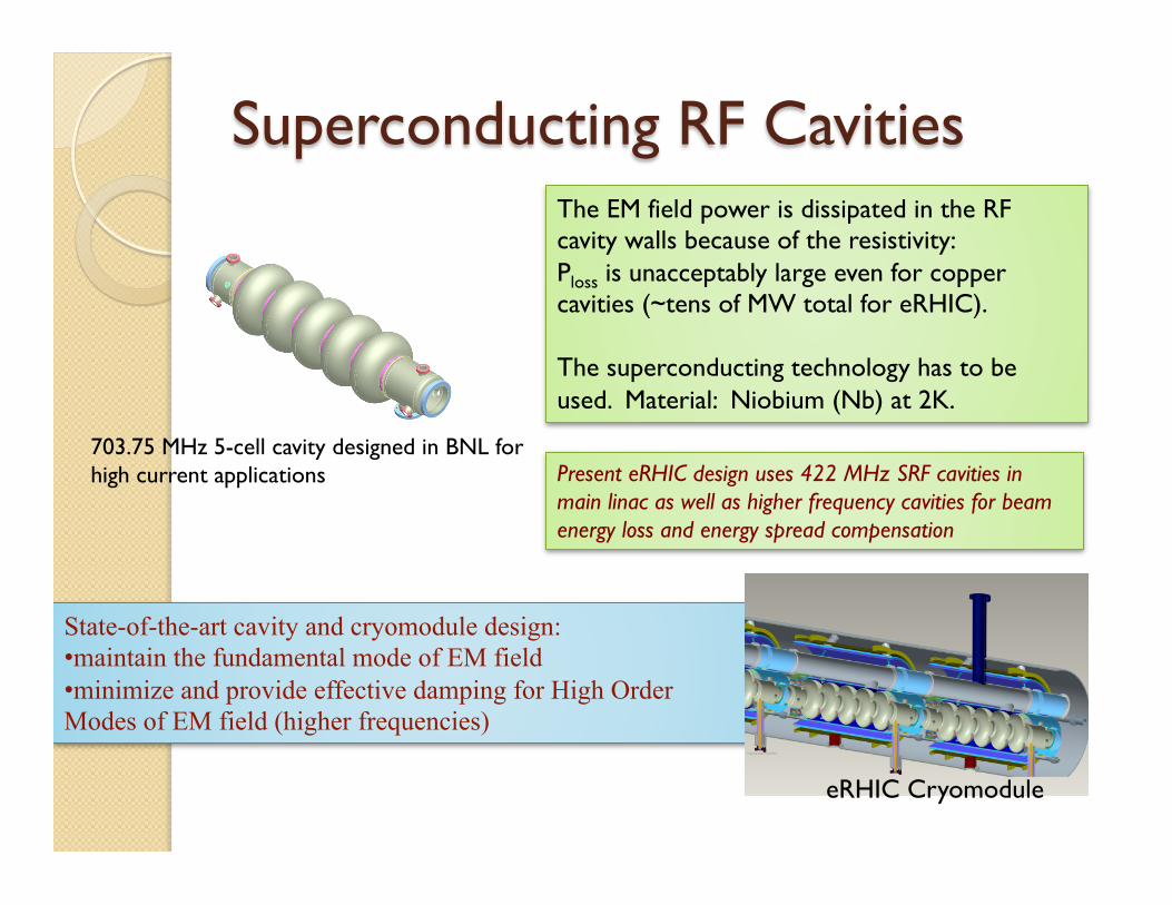
Superconducting RF Cavities
State-of-the-art cavity and cryomodule design: • maintain the fundamental mode of EM field • minimize and provide effective damping for High Order Modes of EM field (higher frequencies)
703.75 MHz 5-cell cavity designed in BNL for high current applications
The EM field power is dissipated in the RF cavity walls because of the resistivity: Ploss is unacceptably large even for copper cavities (~tens of MW total for eRHIC). The superconducting technology has to be used. Material: Niobium (Nb) at 2K.
Present eRHIC design uses 422 MHz SRF cavities in main linac as well as higher frequency cavities for beam energy loss and energy spread compensation
eRHIC Cryomodule

13
NS-FFAG approach for eRHIC • Non-Scaling Fixed Field Alternating Gradient (NS-FFAG) approach is used for
eRHIC recirculation passes. It can transport large energy range."• eRHIC FFAG cell is comprised of two quadrupoles (F & D) whose magnetic axes
are shifted horizontally with respect to each other by an offset Δ ." It can be considered as strongly focusing, bent FODO cell !
Small quadrupole offsets bend the beams adiabatically if bend radius is much larger than cell length!• Orbit and optics dependence on the energy can be accurately found in paraxial
approximation"
High energy FFAG cell
© D.Trbojevic

14
Synchrotron Radiation Effects
Energy loss and energy spread are compensated by high harmonic SRF cavities"
Total SR power 12 MW: operation at 15.9 GeV top energy -> 50 mA operation at 21.2 GeV top energy -> 18 mA
0"
1"
2"
3"
4"
5"
6"
7"
8"
0" 5" 10" 15" 20" 25"
rms$e
nergy$spread
,$MeV
$
Beam$energy,$GeV$
Top"energy"21.2"GeV"
Top"energy"15.9"GeV"
SR power loss per recirculation pass
Accumulated energy spread
© S. Brooks, F. Meot, V. Ptitsyn
Ie=50 mA Ie=18 mA
FFAG lattice was thoroughly optimized on several factors:"• energy acceptance "• orbit spread "• time-of-flight spread "• synchrotron radiation power"
15
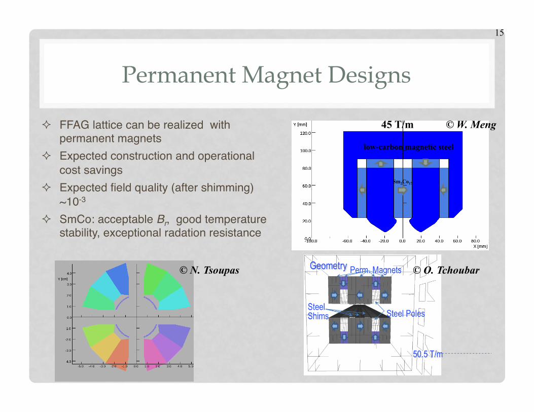
Permanent Magnet Designs
² FFAG lattice can be realized with permanent magnets"
² Expected construction and operational cost savings"
² Expected field quality (after shimming) ~10-3"
² SmCo: acceptable Br, good temperature stability, exceptional radation resistance "
Sm2Co17
low-carbon magnetic steel
45 T/m © W. Meng
© O. Tchoubar © N. Tsoupas

16
Beam Spreader and Combiner © N. Tsoupas
Linac Arcs
• Placed on either side of the linac to separate/combine the 16 beams with different energies between FFAG arcs and CW Linac"
• Match optical function from the arc to the linac"
• Ensure isochronous one turn transport:"
path length and R56 corrections !• Betatron phase advance adjusters"
² 15 cm horizontal separation between individual lines
² Some of the lines are folded into the vertical plane to reduce path length difference
² Vertical magnet chicanes are used for pathlength correction

17
Hadron-Electron Synchronization
Presently accepted solution for the frequency synchronization includes: Ø Hadron delay line Preliminary design provides up to 16 cm path lengthening ability. Ø The RF harmonic switching method; Used to operate with the hadron energies <50 GeV/n
Main synchronization condition: the electron and hadron bunch repetition frequencies at the collision points have to be the same: fbe = fbh The hadron bunch frequency (at the fixed circumference) depends on the hadron energy

18
Hadron Circumference Lengthening and Harmonic Switching
Delay line: max 16cm The operation is possible only above the red line (positive path lengthening) Sharp changes corresponds to the change of electron RF harmonic (he)
Accessible proton energy ranges: 100-250 GeV; 43-46 GeV; 31.6-33.2 GeV; 26.3-27.1 GeV; 23-23.5 GeV
Ce =he5280
Ch
βh
!0.70%
!0.60%
!0.50%
!0.40%
!0.30%
!0.20%
!0.10%
0.00%
0.10%
0.20%
0.30%
20% 40% 60% 80% 100% 120% 140% 160% 180% 200% 220% 240% 260%
Proton
&circ
umference&lengthen
ing,&m
&
Proton&beam&energy,&GeV&
Hadron circumference lenghtening
Linac RF frequency
393.8%
393.9%
394.0%
394.1%
394.2%
20% 30% 40% 50% 60% 70% 80% 90% 100% 110% 120% 130% 140% 150%
Electron
)RF)freq
uency,)M
Hz)
Hadron)beam)energy,)GeV)

19
Electron Polarization in eRHIC • 90% longitudinally polarized e-beam from
DC gun with super-lattice GaAs-photocathode with polarization sign reversal by changing helicity of laser photons."
• Only longitudinal polarization is needed in the IPs. "
• eRHIC avoids lengthy spin rotator insertions. Cost saving."
• Integer number of 180-degrees spin rotations between the gun and IPs"
• With the linac energy of 1.322 GeV the polarization is longitudinal at both experimental IPs"
• To achieve 80% polarization up to 21.2 GeV harmonic cavities are used for the energy spread reduction"
Polarized e-gun
ϕd, γd
ϕ0, γ0
ϕ
stays in horizontal plane and rotates in arcs around
vertical direction
€
v e
€
p e
€
p e
€
ϕ Θ( ) =ϕ0 + a γ θ( )0
Θ
∫ dθ
protons electrons
0"
10"
20"
30"
40"
50"
60"
70"
80"
90"
100"
0" 1" 2" 3" 4" 5" 6" 7" 8" 9" 10"
Polariza(
on,+%
+
rms+bunch+length,+mm+
with energy spread compensation
without energy spread compensation
Dashed – 21.2 GeV Solid – 15.9 GeV

20
Interaction Region with β* = 5 cm"
• 10 mrad crossing angle with crab-crossing"
• Large enough aperture IR SC magnets for forward collision products and with field-free passage for electron beam"
• Recent IR design improvements on the magnet design with electron passage and integration of "
detector components"• 90 degree lattice and beta-beat in
adjacent arcs (ATS) to reach β* of 5 cm and provide effective chromatic corrections!
"
Crab-cavities
p e
Electron passage is arranged between SC coils of hadron magnet
© B. Parker Forward detector
components

21
eRHIC R&D and demonstration tests""• Prototyping of Gatling Gun polarized electron source "• Coherent electron Cooling PoP using 40 GeV/n Au beams in RHIC "• High average current ERL to support operation with high current e-
beam"• FFAG Demo prototype"• Development of high gradient crab cavities within LARP ""
Gatling gun"
CeC PoP"
For more details: Y. Hao’s talk on eRHIC accelerator R&D on Tuesday
LHC crab-cavity prototype"

22
Summary"
• The present cost-effective design of ERL-based eRHIC relies on FFAG lattice of recirculation passes and reaches high luminosity (> 1033 cm-2 s-1) up to 125 GeV CM energy and 145 GeV CM energy for somewhat lower luminosity.
• Studies of design issues specific for the FFAG lattice approach have not revealed showstoppers. Solutions have been found for the optimal FFAG lattice, spreader/combiner, orbit measurement and correction, ion gap formation … .
• Several R&Ds are under way with results expected in 2014-2016
• Modest upgrades to the hadron ring would support highest luminosity (1034 cm-2 s-1).

23
Acknowledgements
for their contributions to the FFAG eRHIC Accelerator design:"
E.C. Aschenauer, M. Bai, S. Belomestnykh, I. Ben-Zvi, S. Brooks, C. Brutus, T. Burton, A. Fedotov, D. Gassner, Y. Hao, Y. Jing, D. Kayran, V. N. Litvinenko, C. Liu, G. Mahler, M. Mapes, G. McIntyre, W. Meng, F. Meot, T. Miller, M. Minty, B.Parker, I. Pinayev, T. Roser, J. Skaritka, O. Tchoubar, P. Thieberger, D. Trbojevic, N. Tsoupas, J. Tuozzolo, E. Wang, G. Wang, Q. Wu, W. Xu!


