20
V-rings
V-rings
T +31 72 514 15 14 E [email protected]
T +31 72 514 18 33E [email protected]
semi-manufactured and finished products of:Eriflon-PTFE - PVDF - PCTFEErtalon - PA6 and PA66Ertacetal - POMErtalyte - PETPNylatronFluorosintTorlonTechtronPEEK/PSU/PEIMerlin-PITrovidur/Epradur PVCMultilene PE and PPpolycarbonateacrylate - PMMA - PETEpratex/Tufnol-PF (lami-nated fabric)Hapa - PF (laminated paper)RX® Grate/GVK (glass-fibre rein-forced plastics)Erlan/Rhino Hyde®-PUR
Should you need a product you cannot find on this page, please call us on our general telephone number. We will be glad to help you further.
T +31 72 514 18 55E [email protected]
pipes and fittings of:• Superflo ABS• Air-Line Xtra• PE• PP• PVC• PVC-C• PVDFball valvesdiaphragm valvesbutterfly valvesglobe valvescheck valvesstrainersoverflow valvesreducing valvessolenoid valvesclampstoolscementsplastic tankswall sleevesrepair clamps
oil sealsEri-sleeves shaft protectingV-ringsPS sealsseals, guide parts and wipers for hydraulic and pneumatic cylindersMultisealsOmniseals® spring actuatedPTFE sealsend capsKVSP Kalrez® valve stem packingslubricantsgreasesleak detection spraysliquid sealants
T +31 72 514 18 11E [email protected]
T +31 72 514 18 66E [email protected]
T +31 72 514 18 22E [email protected]
rubber moulded partsprofiles of:• cellular rubber• sponge rubber• solid rubberinflatable sealsO-ringsX-ringsback-up ringscordsadhesivesboxes of assorted O-ringsvibration absorbers
hoses of:• rubber• plastic• PTFE• metalhose couplingscoupling systemshose clampshose reelshose reel cartshydraulic hosesfittings and couplings for hy-draulicsexpansion joints of:• rubber• metal• fabric• PTFE
metallic and semi-metallic gaskets:• spiral wound• ring type joint• serrated• insulating setsflange gaskets and die-cut parts of:• elastomers• fibre sheet• PTFE sheet/tape• graphite sheetstuffing-box packingsmechanical seals
globe valvesgate valvescheck valvesstrainerssight glassessteam trapsreducing valvessafety valvesgauge glassesoverflow valvesvacuum and air reliefe valvesball valvesbutterfly valvespneumatic and electric actuatorsdiaphragm valvespinch valvesmeasurement and regulation components for: • pressure • temperature • flow • level control valvessolenoid valves
T +31 72 514 18 44E [email protected]
direct lines
www.eriks.nl
T +31 72 514 18 00E [email protected]
plasTic pipinghosEs, accEssoriEs
and Expansion joinTs indusTrial plasTicsvalvEs andinsTrumEnTaTion
FlangE gaskETs dynamic sEals o-ring & TEchnical rubbEr gEnEral
v-rings
ERIKS bvP.O. Boxs 2801800 BK Alkmaar
T +31 72 514 15 14F +31 72 515 56 45
846047-2008
Seal ing technology
2
Content
PageThe sealing principle . . . . . . . . . . . . . . . . . . . . . . . . . . . . . . . . . 3The funcioning . . . . . . . . . . . . . . . . . . . . . . . . . . . . . . . . . . . . . 3Basic profiles . . . . . . . . . . . . . . . . . . . . . . . . . . . . . . . . . . . . . . 3Materials . . . . . . . . . . . . . . . . . . . . . . . . . . . . . . . . . . . . . . . . . . 3Applications . . . . . . . . . . . . . . . . . . . . . . . . . . . . . . . . . . . . . . . 4Counterface demands . . . . . . . . . . . . . . . . . . . . . . . . . . . . . . . . 5Roughness of the counterface . . . . . . . . . . . . . . . . . . . . . . . . . . 5RX® V-ring type A . . . . . . . . . . . . . . . . . . . . . . . . . . . . . . . . . . . 6RX® V-ring type S . . . . . . . . . . . . . . . . . . . . . . . . . . . . . . . . . . . 9RX® V-ring type L NBR . . . . . . . . . . . . . . . . . . . . . . . . . . . . . . 11RX® V-ring type E NBR . . . . . . . . . . . . . . . . . . . . . . . . . . . . . . 12Nomograph for the peripheral speed . . . . . . . . . . . . . . . . . . . . 14Friction . . . . . . . . . . . . . . . . . . . . . . . . . . . . . . . . . . . . . . . . . . 15Mounting the ERIKS V-ring . . . . . . . . . . . . . . . . . . . . . . . . . . . 15
Liability
The information in this documentation is based on a long-year experience on the application of sealing elements. In spite of this experience, in some cases undefined parameters can limit the theoretical tasks considerably. In such cases therefore we cannot give any guarantees for the accuracy of our recommendations. We request you to consult us in case any extraordinary demands are put to the product. Dimensions and images can be changed at any moment when new experiences become available. All rights related to this documentation are reserved by ERIKS. No prints or copies of this documentation can be used without the explicit approval of ERIKS.
V-r ings
3
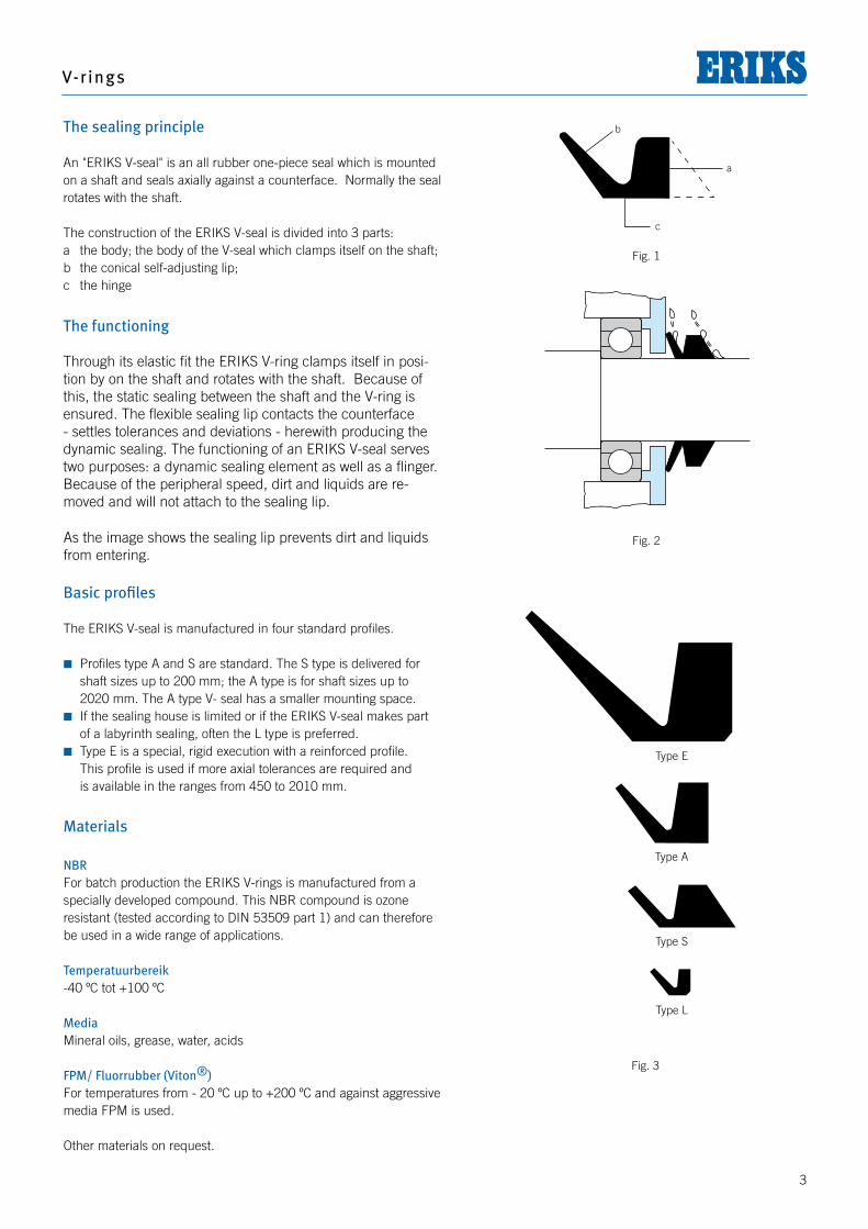
The sealing principle
An "ERIKS V-seal" is an all rubber one-piece seal which is mounted on a shaft and seals axially against a counterface. Normally the seal rotates with the shaft.
The construction of the ERIKS V-seal is divided into 3 parts:a the body; the body of the V-seal which clamps itself on the shaft;b the conical self-adjusting lip;c the hinge
The functioning
Through its elastic fit the ERIKS V-ring clamps itself in posi-tion by on the shaft and rotates with the shaft. Because of this, the static sealing between the shaft and the V-ring is ensured. The flexible sealing lip contacts the counterface - settles tolerances and deviations - herewith producing the dynamic sealing. The functioning of an ERIKS V-seal serves two purposes: a dynamic sealing element as well as a flinger. Because of the peripheral speed, dirt and liquids are re-moved and will not attach to the sealing lip.
b
a
c
As the image shows the sealing lip prevents dirt and liquids from entering.
Basic profiles
The ERIKS V-seal is manufactured in four standard profiles.
Profiles type A and S are standard. The S type is delivered for shaft sizes up to 200 mm; the A type is for shaft sizes up to
2020 mm. The A type V- seal has a smaller mounting space. If the sealing house is limited or if the ERIKS V-seal makes part
of a labyrinth sealing, often the L type is preferred. Type E is a special, rigid execution with a reinforced profile. This profile is used if more axial tolerances are required and is available in the ranges from 450 to 2010 mm.
Materials
NBR For batch production the ERIKS V-rings is manufactured from a specially developed compound. This NBR compound is ozone resistant (tested according to DIN 53509 part 1) and can therefore be used in a wide range of applications.
Temperatuurbereik-40 ºC tot +100 ºC
MediaMineral oils, grease, water, acids
FPM/ Fluorrubber (Viton®)For temperatures from - 20 ºC up to +200 ºC and against aggressive media FPM is used.
Other materials on request.
Fig. 1
Fig. 2
Type E
Type A
Type S
Type L
Fig. 3
Seal ing technology
4
Applications ERIKS V-rings have certain technical advantages:1. Low friction and therefore lower power losses related to the ap-
plication of oil seals;2. Long lifetime;3. Simple construction; no seal housing is required;4. The shafts do not need a special surface treatment;5. Simple mounting;6. No wear of the shaft;7. Dual function: as a seal and as a flinger through which possible
dirt and liquids are thrown away;8. The flexible lip is unlikely to become damaged during storage and
assembly;9. An ERIKS V-ring is applicable for a wide range of shaft diameters.
With 85 sizes you have access to an assortment of ERIKS V-seals for shaft sizes from 3 till 2000 mm (1/8" to 80");
10. Suitable for high RPM;11. Misalignment of the shaft has no negative effect on the function-
ing of the V-seal;12. Attractive pricing.
Where is the V-seal used?The ERIKS V-ring is used as a pressureless sealing preventing dirt, water, oil splash and dust to enter the system.
The most familiar applications are:Pumps, electro motors, paper machines, rolling mils, metal - and wood treatment devices, agricultural machines, etc.
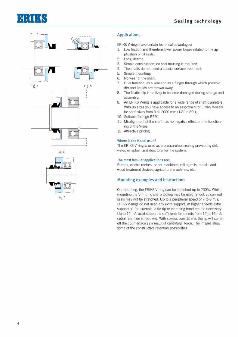
Mounting examples and instructions
On mounting, the ERIKS V-ring can be stretched up to 200%. While mounting the V-ring no sharp tooling may be used. Shock vulcanized seals may not be stretched. Up to a peripheral speed of 7 to 8 m/s, ERIKS V-rings do not need any extra support. At higher speeds extra support of, for example, a tie-rip or clamping band can be necessary. Up to 12 m/s axial support is sufficient; for speeds from 12 to 15 m/s radial retention is required. With speeds over 15 m/s the lip will come off the counterface as a result of centrifugal force. The images show some of the constructive retention possibilities.
Fig. 4 Fig. 5
Fig. 6
Fig. 7
V-r ings
5
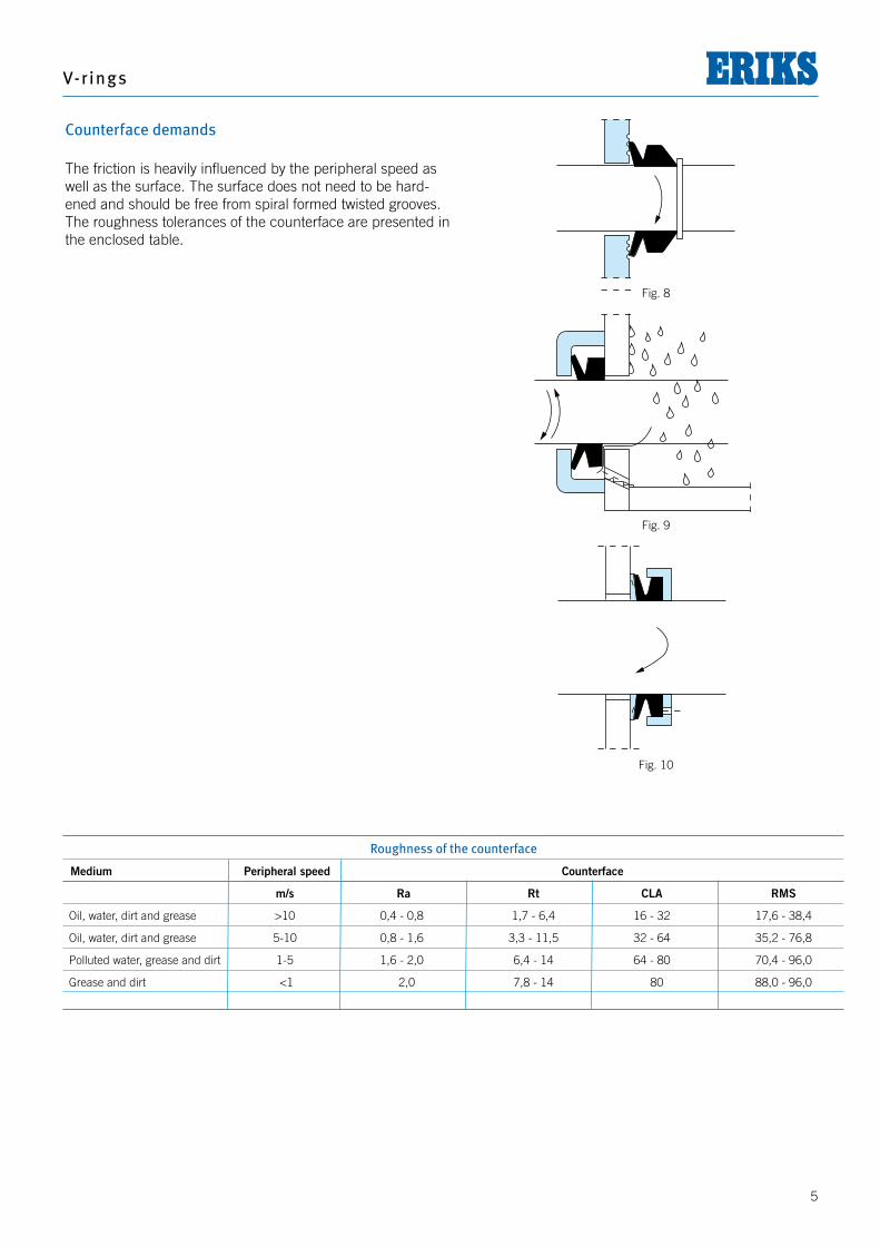
Roughness of the counterface
Medium Peripheral speed Counterface
m/s Ra Rt CLA RMS
Oil, water, dirt and grease >10 0,4 - 0,8 1,7 - 6,4 16 - 32 17,6 - 38,4
Oil, water, dirt and grease 5-10 0,8 - 1,6 3,3 - 11,5 32 - 64 35,2 - 76,8
Polluted water, grease and dirt 1-5 1,6 - 2,0 6,4 - 14 64 - 80 70,4 - 96,0
Grease and dirt <1 2,0 7,8 - 14 80 88,0 - 96,0
Counterface demands
The friction is heavily influenced by the peripheral speed as well as the surface. The surface does not need to be hard-ened and should be free from spiral formed twisted grooves. The roughness tolerances of the counterface are presented in the enclosed table.
Fig. 8
Fig. 9
Fig. 10
Seal ing technology
6
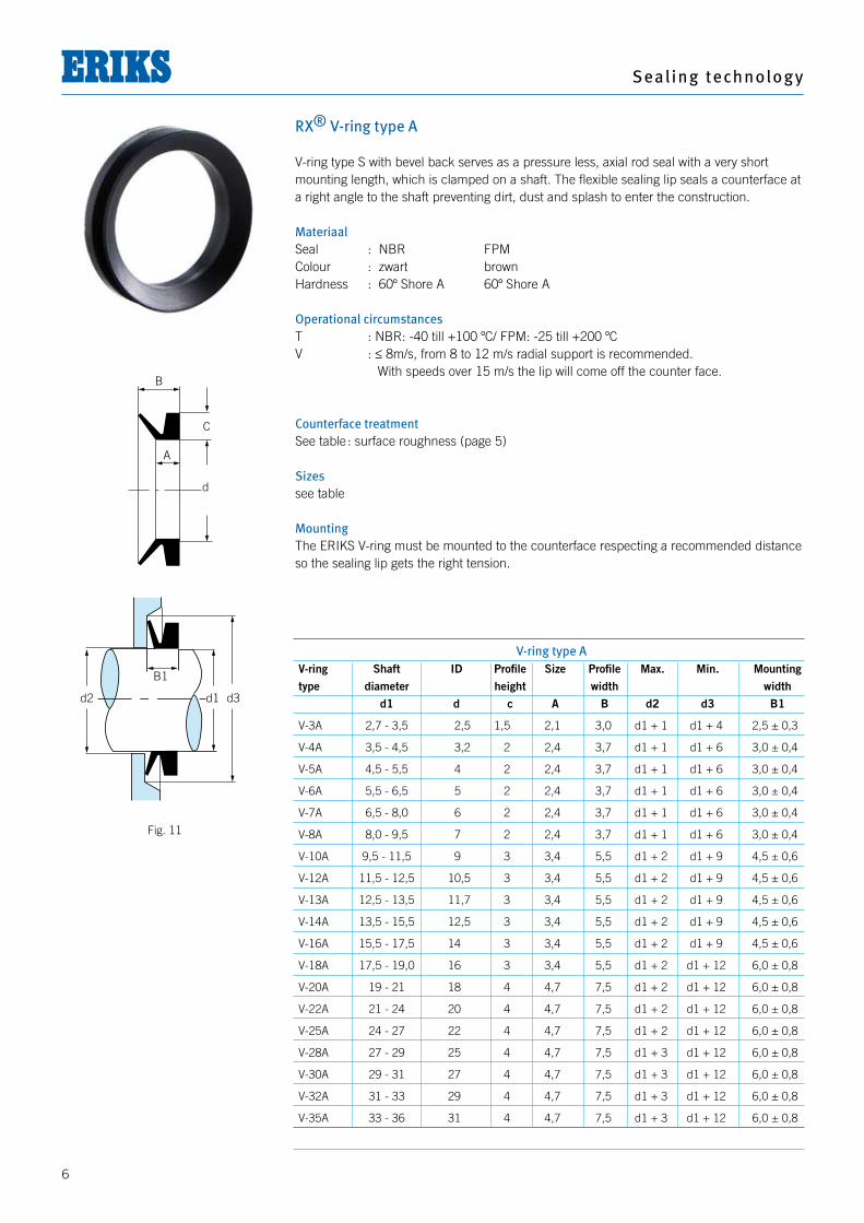
RX® V-ring type A
V-ring type S with bevel back serves as a pressure less, axial rod seal with a very short mounting length, which is clamped on a shaft. The flexible sealing lip seals a counterface at a right angle to the shaft preventing dirt, dust and splash to enter the construction. MateriaalSeal : NBR FPMColour : zwart brownHardness : 60º Shore A 60º Shore A Operational circumstancesT : NBR: -40 till +100 ºC/ FPM: -25 till +200 ºC V : ≤ 8m/s, from 8 to 12 m/s radial support is recommended. With speeds over 15 m/s the lip will come off the counter face.
Counterface treatmentSee table : surface roughness (page 5)
Sizessee table
MountingThe ERIKS V-ring must be mounted to the counterface respecting a recommended distance so the sealing lip gets the right tension.
B
C
A
d
d2 d1 d3
B1
V-ring type A V-ring Shaft ID Profile Size Profile Max. Min. Mounting type diameter height width width d1 d c A B d2 d3 B1
V-3A 2,7 - 3,5 2,5 1,5 2,1 3,0 d1 + 1 d1 + 4 2,5 ± 0,3
V-4A 3,5 - 4,5 3,2 2 2,4 3,7 d1 + 1 d1 + 6 3,0 ± 0,4
V-5A 4,5 - 5,5 4 2 2,4 3,7 d1 + 1 d1 + 6 3,0 ± 0,4
V-6A 5,5 - 6,5 5 2 2,4 3,7 d1 + 1 d1 + 6 3,0 ± 0,4
V-7A 6,5 - 8,0 6 2 2,4 3,7 d1 + 1 d1 + 6 3,0 ± 0,4
V-8A 8,0 - 9,5 7 2 2,4 3,7 d1 + 1 d1 + 6 3,0 ± 0,4
V-10A 9,5 - 11,5 9 3 3,4 5,5 d1 + 2 d1 + 9 4,5 ± 0,6
V-12A 11,5 - 12,5 10,5 3 3,4 5,5 d1 + 2 d1 + 9 4,5 ± 0,6
V-13A 12,5 - 13,5 11,7 3 3,4 5,5 d1 + 2 d1 + 9 4,5 ± 0,6
V-14A 13,5 - 15,5 12,5 3 3,4 5,5 d1 + 2 d1 + 9 4,5 ± 0,6
V-16A 15,5 - 17,5 14 3 3,4 5,5 d1 + 2 d1 + 9 4,5 ± 0,6
V-18A 17,5 - 19,0 16 3 3,4 5,5 d1 + 2 d1 + 12 6,0 ± 0,8
V-20A 19 - 21 18 4 4,7 7,5 d1 + 2 d1 + 12 6,0 ± 0,8
V-22A 21 - 24 20 4 4,7 7,5 d1 + 2 d1 + 12 6,0 ± 0,8
V-25A 24 - 27 22 4 4,7 7,5 d1 + 2 d1 + 12 6,0 ± 0,8
V-28A 27 - 29 25 4 4,7 7,5 d1 + 3 d1 + 12 6,0 ± 0,8
V-30A 29 - 31 27 4 4,7 7,5 d1 + 3 d1 + 12 6,0 ± 0,8
V-32A 31 - 33 29 4 4,7 7,5 d1 + 3 d1 + 12 6,0 ± 0,8
V-35A 33 - 36 31 4 4,7 7,5 d1 + 3 d1 + 12 6,0 ± 0,8
Fig. 11
V-r ings
7
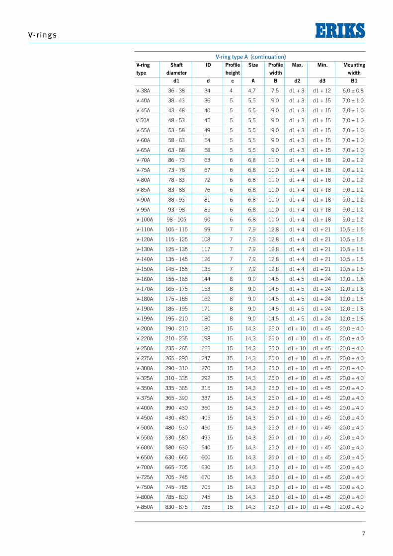
V-ring type A (continuation) V-ring Shaft ID Profile Size Profile Max. Min. Mounting type diameter height width width d1 d c A B d2 d3 B1
V-38A 36 - 38 34 4 4,7 7,5 d1 + 3 d1 + 12 6,0 ± 0,8
V-40A 38 - 43 36 5 5,5 9,0 d1 + 3 d1 + 15 7,0 ± 1,0
V-45A 43 - 48 40 5 5,5 9,0 d1 + 3 d1 + 15 7,0 ± 1,0
V-50A 48 - 53 45 5 5,5 9,0 d1 + 3 d1 + 15 7,0 ± 1,0
V-55A 53 - 58 49 5 5,5 9,0 d1 + 3 d1 + 15 7,0 ± 1,0
V-60A 58 - 63 54 5 5,5 9,0 d1 + 3 d1 + 15 7,0 ± 1,0
V-65A 63 - 68 58 5 5,5 9,0 d1 + 3 d1 + 15 7,0 ± 1,0
V-70A 86 - 73 63 6 6,8 11,0 d1 + 4 d1 + 18 9,0 ± 1,2
V-75A 73 - 78 67 6 6,8 11,0 d1 + 4 d1 + 18 9,0 ± 1,2
V-80A 78 - 83 72 6 6,8 11,0 d1 + 4 d1 + 18 9,0 ± 1,2
V-85A 83 - 88 76 6 6,8 11,0 d1 + 4 d1 + 18 9,0 ± 1,2
V-90A 88 - 93 81 6 6,8 11,0 d1 + 4 d1 + 18 9,0 ± 1,2
V-95A 93 - 98 85 6 6,8 11,0 d1 + 4 d1 + 18 9,0 ± 1,2
V-100A 98 - 105 90 6 6,8 11,0 d1 + 4 d1 + 18 9,0 ± 1,2
V-110A 105 - 115 99 7 7,9 12,8 d1 + 4 d1 + 21 10,5 ± 1,5
V-120A 115 - 125 108 7 7,9 12,8 d1 + 4 d1 + 21 10,5 ± 1,5
V-130A 125 - 135 117 7 7,9 12,8 d1 + 4 d1 + 21 10,5 ± 1,5
V-140A 135 - 145 126 7 7,9 12,8 d1 + 4 d1 + 21 10,5 ± 1,5
V-150A 145 - 155 135 7 7,9 12,8 d1 + 4 d1 + 21 10,5 ± 1,5
V-160A 155 - 165 144 8 9,0 14,5 d1 + 5 d1 + 24 12,0 ± 1,8
V-170A 165 - 175 153 8 9,0 14,5 d1 + 5 d1 + 24 12,0 ± 1,8
V-180A 175 - 185 162 8 9,0 14,5 d1 + 5 d1 + 24 12,0 ± 1,8
V-190A 185 - 195 171 8 9,0 14,5 d1 + 5 d1 + 24 12,0 ± 1,8
V-199A 195 - 210 180 8 9,0 14,5 d1 + 5 d1 + 24 12,0 ± 1,8
V-200A 190 - 210 180 15 14,3 25,0 d1 + 10 d1 + 45 20,0 ± 4,0
V-220A 210 - 235 198 15 14,3 25,0 d1 + 10 d1 + 45 20,0 ± 4,0
V-250A 235 - 265 225 15 14,3 25,0 d1 + 10 d1 + 45 20,0 ± 4,0
V-275A 265 - 290 247 15 14,3 25,0 d1 + 10 d1 + 45 20,0 ± 4,0
V-300A 290 - 310 270 15 14,3 25,0 d1 + 10 d1 + 45 20,0 ± 4,0
V-325A 310 - 335 292 15 14,3 25,0 d1 + 10 d1 + 45 20,0 ± 4,0
V-350A 335 - 365 315 15 14,3 25,0 d1 + 10 d1 + 45 20,0 ± 4,0
V-375A 365 - 390 337 15 14,3 25,0 d1 + 10 d1 + 45 20,0 ± 4,0
V-400A 390 - 430 360 15 14,3 25,0 d1 + 10 d1 + 45 20,0 ± 4,0
V-450A 430 - 480 405 15 14,3 25,0 d1 + 10 d1 + 45 20,0 ± 4,0
V-500A 480 - 530 450 15 14,3 25,0 d1 + 10 d1 + 45 20,0 ± 4,0
V-550A 530 - 580 495 15 14,3 25,0 d1 + 10 d1 + 45 20,0 ± 4,0
V-600A 580 - 630 540 15 14,3 25,0 d1 + 10 d1 + 45 20,0 ± 4,0
V-650A 630 - 665 600 15 14,3 25,0 d1 + 10 d1 + 45 20,0 ± 4,0
V-700A 665 - 705 630 15 14,3 25,0 d1 + 10 d1 + 45 20,0 ± 4,0
V-725A 705 - 745 670 15 14,3 25,0 d1 + 10 d1 + 45 20,0 ± 4,0
V-750A 745 - 785 705 15 14,3 25,0 d1 + 10 d1 + 45 20,0 ± 4,0
V-800A 785 - 830 745 15 14,3 25,0 d1 + 10 d1 + 45 20,0 ± 4,0
V-850A 830 - 875 785 15 14,3 25,0 d1 + 10 d1 + 45 20,0 ± 4,0
Seal ing technology
8
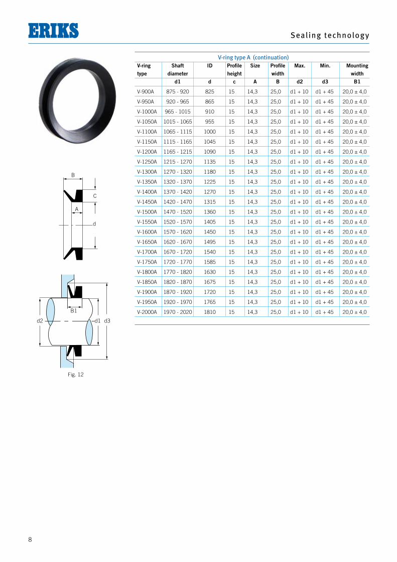
V-ring type A (continuation) V-ring Shaft ID Profile Size Profile Max. Min. Mounting type diameter height width width d1 d c A B d2 d3 B1
V-900A 875 - 920 825 15 14,3 25,0 d1 + 10 d1 + 45 20,0 ± 4,0
V-950A 920 - 965 865 15 14,3 25,0 d1 + 10 d1 + 45 20,0 ± 4,0
V-1000A 965 - 1015 910 15 14,3 25,0 d1 + 10 d1 + 45 20,0 ± 4,0
V-1050A 1015 - 1065 955 15 14,3 25,0 d1 + 10 d1 + 45 20,0 ± 4,0
V-1100A 1065 - 1115 1000 15 14,3 25,0 d1 + 10 d1 + 45 20,0 ± 4,0
V-1150A 1115 - 1165 1045 15 14,3 25,0 d1 + 10 d1 + 45 20,0 ± 4,0
V-1200A 1165 - 1215 1090 15 14,3 25,0 d1 + 10 d1 + 45 20,0 ± 4,0
V-1250A 1215 - 1270 1135 15 14,3 25,0 d1 + 10 d1 + 45 20,0 ± 4,0
V-1300A 1270 - 1320 1180 15 14,3 25,0 d1 + 10 d1 + 45 20,0 ± 4,0
V-1350A 1320 - 1370 1225 15 14,3 25,0 d1 + 10 d1 + 45 20,0 ± 4,0
V-1400A 1370 - 1420 1270 15 14,3 25,0 d1 + 10 d1 + 45 20,0 ± 4,0
V-1450A 1420 - 1470 1315 15 14,3 25,0 d1 + 10 d1 + 45 20,0 ± 4,0
V-1500A 1470 - 1520 1360 15 14,3 25,0 d1 + 10 d1 + 45 20,0 ± 4,0
V-1550A 1520 - 1570 1405 15 14,3 25,0 d1 + 10 d1 + 45 20,0 ± 4,0
V-1600A 1570 - 1620 1450 15 14,3 25,0 d1 + 10 d1 + 45 20,0 ± 4,0
V-1650A 1620 - 1670 1495 15 14,3 25,0 d1 + 10 d1 + 45 20,0 ± 4,0
V-1700A 1670 - 1720 1540 15 14,3 25,0 d1 + 10 d1 + 45 20,0 ± 4,0
V-1750A 1720 - 1770 1585 15 14,3 25,0 d1 + 10 d1 + 45 20,0 ± 4,0
V-1800A 1770 - 1820 1630 15 14,3 25,0 d1 + 10 d1 + 45 20,0 ± 4,0
V-1850A 1820 - 1870 1675 15 14,3 25,0 d1 + 10 d1 + 45 20,0 ± 4,0
V-1900A 1870 - 1920 1720 15 14,3 25,0 d1 + 10 d1 + 45 20,0 ± 4,0
V-1950A 1920 - 1970 1765 15 14,3 25,0 d1 + 10 d1 + 45 20,0 ± 4,0
V-2000A 1970 - 2020 1810 15 14,3 25,0 d1 + 10 d1 + 45 20,0 ± 4,0
B
C
A
d
d2 d1 d3
B1
Fig. 12
V-r ings
9
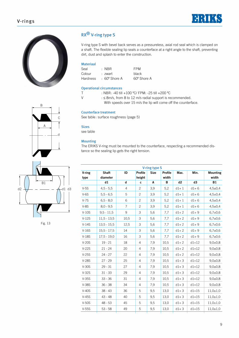
RX® V-ring type S V-ring type S with bevel back serves as a pressureless, axial rod seal which is clamped on a shaft. The flexible sealing lip seals a counterface at a right angle to the shaft, preventing dirt, dust and splash to enter the construction. MateriaalSeal : NBR FPMColour : zwart blackHardness : 60º Shore A 60º Shore A Operational circumstancesT : NBR: -40 till +100 ºC/ FPM: -25 till +200 ºC V : ≤ 8m/s, from 8 to 12 m/s radial support is recommended. With speeds over 15 m/s the lip will come off the counterface.
Counterface treatmentSee table : surface roughness (page 5)
Sizessee table
MountingThe ERIKS V-ring must be mounted to the counterface, respecting a recommended dis-tance so the sealing lip gets the right tension.
B
C
A
d
d2 d1 d3
B1
V-ring type S V-ring Shaft ID Profile Size Profile Max. Min. Mounting type diameter height width width d1 d c A B d2 d3 B1
V-5S 4,5 - 5,5 4 2 3,9 5,2 d1+ 1 d1+ 6 4,5±0,4
V-6S 5,5 - 6,5 5 2 3,9 5,2 d1+ 1 d1+ 6 4,5±0,4
V-7S 6,5 - 8,0 6 2 3,9 5,2 d1+ 1 d1+ 6 4,5±0,4
V-8S 8,0 - 9,5 7 2 3,9 5,2 d1+ 1 d1+ 6 4,5±0,4
V-10S 9,5 - 11,5 9 3 5,6 7,7 d1+ 2 d1+ 9 6,7±0,6
V-12S 11,5 - 13,5 10,5 3 5,6 7,7 d1+ 2 d1+ 9 6,7±0,6
V-14S 13,5 - 15,5 12,5 3 5,6 7,7 d1+ 2 d1+ 9 6,7±0,6
V-16S 15,5 - 17,5 14 3 5,6 7,7 d1+ 2 d1+ 9 6,7±0,6
V-18S 17,5 - 19,0 16 3 5,6 7,7 d1+ 2 d1+ 9 6,7±0,6
V-20S 19 - 21 18 4 7,9 10,5 d1+ 2 d1+12 9,0±0,8
V-22S 21 - 24 20 4 7,9 10,5 d1+ 2 d1+12 9,0±0,8
V-25S 24 - 27 22 4 7,9 10,5 d1+ 2 d1+12 9,0±0,8
V-28S 27 - 29 25 4 7,9 10,5 d1+ 3 d1+12 9,0±0,8
V-30S 29 - 31 27 4 7,9 10,5 d1+ 3 d1+12 9,0±0,8
V-32S 31 - 33 29 4 7,9 10,5 d1+ 3 d1+12 9,0±0,8
V-35S 33 - 36 31 4 7,9 10,5 d1+ 3 d1+12 9,0±0,8
V-38S 36 - 38 34 4 7,9 10,5 d1+ 3 d1+12 9,0±0,8
V-40S 38 - 43 36 5 9,5 13,0 d1+ 3 d1+15 11,0±1,0
V-45S 43 - 48 40 5 9,5 13,0 d1+ 3 d1+15 11,0±1,0
V-50S 48 - 53 45 5 9,5 13,0 d1+ 3 d1+15 11,0±1,0
V-55S 53 - 58 49 5 9,5 13,0 d1+ 3 d1+15 11,0±1,0
Fig. 13
Seal ing technology
10
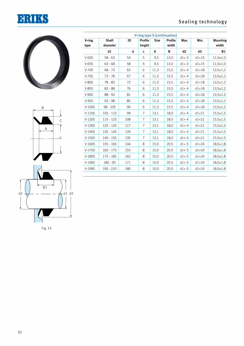
V-ring type S (continuation) V-ring Shaft ID Profile Size Profile Max. Min. Mounting type diameter height width width
d1 d c A B d2 d3 B1
V-60S 58 - 63 54 5 9,5 13,0 d1+ 3 d1+15 11,0±1,0
V-65S 63 - 68 58 5 9,5 13,0 d1+ 3 d1+15 11,0±1,0
V-70S 68 - 73 63 6 11,3 15,5 d1+ 4 d1+18 13,5±1,2
V-75S 73 - 78 67 6 11,3 15,5 d1+ 4 d1+18 13,5±1,2
V-80S 78 - 83 72 6 11,3 15,5 d1+ 4 d1+18 13,5±1,2
V-85S 83 - 88 76 6 11,3 15,5 d1+ 4 d1+18 13,5±1,2
V-90S 88 - 93 81 6 11,3 15,5 d1+ 4 d1+18 13,5±1,2
V-95S 93 - 98 85 6 11,3 15,5 d1+ 4 d1+18 13,5±1,2
V-100S 98 - 105 90 6 11,3 15,5 d1+ 4 d1+18 13,5±1,2
V-110S 105 - 115 99 7 13,1 18,0 d1+ 4 d1+21 15,5±1,5
V-120S 115 - 125 108 7 13,1 18,0 d1+ 4 d1+21 15,5±1,5
V-130S 125 - 135 117 7 13,1 18,0 d1+ 4 d1+21 15,5±1,5
V-140S 135 - 145 126 7 13,1 18,0 d1+ 4 d1+21 15,5±1,5
V-150S 145 - 155 135 7 13,1 18,0 d1+ 4 d1+21 15,5±1,5
V-160S 155 - 165 144 8 15,0 20,5 d1+ 5 d1+24 18,0±1,8
V-170S 165 - 175 153 8 15,0 20,5 d1+ 5 d1+24 18,0±1,8
V-180S 175 - 185 162 8 15,0 20,5 d1+ 5 d1+24 18,0±1,8
V-190S 185 - 95 171 8 15,0 20,5 d1+ 5 d1+24 18,0±1,8
V-199S 195 - 210 180 8 15,0 20,5 d1+ 5 d1+24 18,0±1,8
B
C
A
d
d2 d1 d3
B1
Fig. 14
V-r ings
11
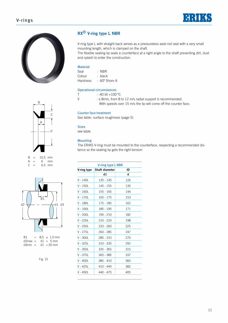
RX® V-ring type L NBR
V-ring type L with straight back serves as a pressureless axial rod seal with a very small mounting length, which is clamped on the shaft. The flexible sealing lip seals a counterface at a right angle to the shaft preventing dirt, dust and splash to enter the construction. MaterialSeal : NBRColour : blackHardness : 60º Shore A Operational circumstancesT : -40 till +100 ºC V : ≤ 8m/s, from 8 to 12 m/s radial support is recommended. With speeds over 15 m/s the lip will come off the counter face.
Counter face treatmentSee table : surface roughness (page 5)
Sizessee table
MountingThe ERIKS V-ring must be mounted to the counterface, respecting a recommended dis-tance so the sealing lip gets the right tension
B
C
A
d
d2 d1 d3
B1
V-ring type L NBRV-ring type Shaft diameter ID d1 d
V - 140L 135 - 145 126
V - 150L 145 - 155 135
V - 160L 155 - 165 144
V - 170L 165 - 175 153
V - 180L 175 - 185 162
V - 190L 185 - 195 171
V - 200L 195 - 210 182
V - 220L 210 - 233 198
V - 250L 233 - 260 225
V - 275L 260 - 285 247
V - 300L 285 - 310 270
V - 325L 310 - 335 292
V - 350L 335 - 365 315
V - 375L 365 - 385 337
V - 400L 385 - 410 360
V - 425L 410 - 440 382
V - 450L 440 - 475 405
B
C
A
d
d2 d1 d3
B1
B = 10,5 mmA = 6 mmC = 6,5 mm
B1 = 8,5 ± 1,5 mmd2max = d1 + 5 mmd3min = d1 + 20 mm
Fig. 15
Seal ing technology
12
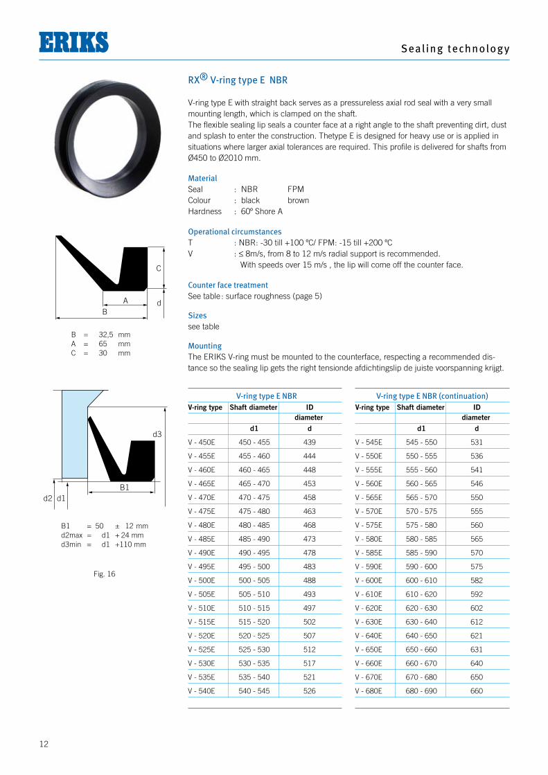
RX® V-ring type E NBR V-ring type E with straight back serves as a pressureless axial rod seal with a very small mounting length, which is clamped on the shaft. The flexible sealing lip seals a counter face at a right angle to the shaft preventing dirt, dust and splash to enter the construction. Thetype E is designed for heavy use or is applied in situations where larger axial tolerances are required. This profile is delivered for shafts from Ø450 to Ø2010 mm.
MaterialSeal : NBR FPMColour : black brownHardness : 60º Shore A
Operational circumstancesT : NBR: -30 till +100 ºC/ FPM: -15 till +200 ºC V : ≤ 8m/s, from 8 to 12 m/s radial support is recommended. With speeds over 15 m/s , the lip will come off the counter face.
Counter face treatmentSee table : surface roughness (page 5)
Sizessee table
MountingThe ERIKS V-ring must be mounted to the counterface, respecting a recommended dis-tance so the sealing lip gets the right tensionde afdichtingslip de juiste voorspanning krijgt.
AB
C
d
d3
B1d2 d1
V-ring type E NBRV-ring type Shaft diameter ID diameter d1 d
V - 450E 450 - 455 439
V - 455E 455 - 460 444
V - 460E 460 - 465 448
V - 465E 465 - 470 453
V - 470E 470 - 475 458
V - 475E 475 - 480 463
V - 480E 480 - 485 468
V - 485E 485 - 490 473
V - 490E 490 - 495 478
V - 495E 495 - 500 483
V - 500E 500 - 505 488
V - 505E 505 - 510 493
V - 510E 510 - 515 497
V - 515E 515 - 520 502
V - 520E 520 - 525 507
V - 525E 525 - 530 512
V - 530E 530 - 535 517
V - 535E 535 - 540 521
V - 540E 540 - 545 526
V-ring type E NBR (continuation)V-ring type Shaft diameter ID diameter d1 d
V - 545E 545 - 550 531
V - 550E 550 - 555 536
V - 555E 555 - 560 541
V - 560E 560 - 565 546
V - 565E 565 - 570 550
V - 570E 570 - 575 555
V - 575E 575 - 580 560
V - 580E 580 - 585 565
V - 585E 585 - 590 570
V - 590E 590 - 600 575
V - 600E 600 - 610 582
V - 610E 610 - 620 592
V - 620E 620 - 630 602
V - 630E 630 - 640 612
V - 640E 640 - 650 621
V - 650E 650 - 660 631
V - 660E 660 - 670 640
V - 670E 670 - 680 650
V - 680E 680 - 690 660
B = 32,5 mmA = 65 mmC = 30 mm
B1 = 50 ± 12 mmd2max = d1 + 24 mmd3min = d1 + 110 mm
Fig. 16
V-r ings
13
V-ring type E NBR (continuation)V-ring type Shaft diameter ID diameter d1 d
V - 690E 690 - 700 670
V - 700E 700 - 710 680
V - 710E 710 - 720 689
V - 720E 720 - 730 699
V - 730E 730 - 740 709
V - 740E 740 - 750 718
V - 750E 750 - 758 728
V - 760E 758 - 766 735
V - 770E 766 - 774 743
V - 780E 774 - 783 751
V - 790E 783 - 792 759
V - 800E 792 - 801 768
V - 810E 801 - 810 777
V - 820E 810 - 821 786
V - 830E 821 - 831 796
V - 840E 831 - 841 805
V - 850E 841 - 851 814
V - 860E 851 - 861 824
V - 870E 861 - 871 833
V - 880E 871 - 882 843
V - 890E 882 - 892 853
V - 900E 892 - 912 871
V - 920E 912 - 922 880
V - 930E 922 - 933 890
V - 940E 933 - 944 900
V - 950E 944 - 955 911
V - 960E 955 - 966 921
V - 970E 966 - 977 932
V - 980E 977 - 988 942
V - 990E 988 - 999 953
V - 1000E 999 - 1010 963
V - 1020E 1010 - 1025 973
V - 1040E 1025 - 1045 990
V - 1060E 1045 - 1065 1008
V - 1080E 1065 - 1085 1027
V - 1100E 1085 - 1105 1045
V - 1120E 1105 - 1125 1065
V - 1140E 1125 - 1145 1084
V - 1160E 1145 - 1165 1103
V - 1180E 1165 - 1185 1121
V-ring type E NBR continuation)V-ring type Shaft diameter ID diameter d1 d
V - 1200E 1185 - 1205 1139
V - 1220E 1205 - 1225 1157
V - 1240E 1225 - 1245 1176
V - 1260E 1245 - 1270 1195
V - 1280E 1270 - 1295 1218
V - 1300E 1295 - 1315 1240
V - 1325E 1315 - 1340 1259
V - 1350E 1340 - 1365 1281
V - 1375E 1365 - 1390 1305
V - 1400E 1390 - 1415 1328
V - 1425E 1415 - 1440 1350
V - 1450E 1440 - 1465 1374
V - 1475E 1465 - 1490 1397
V - 1500E 1490 - 1515 1419
V - 1525E 1515 - 1540 1443
V - 1550E 1540 - 1570 1467
V - 1575E 1570 - 1600 1495
V - 1600E 1600 - 1640 1524
V - 1650E 1640 - 1680 1559
V - 1700E 1680 - 1720 1596
V - 1750E 1720 - 1765 1632
V - 1800E 1765 - 1810 1671
V - 1850E 1810 - 1855 1714
V - 1900E 1855 - 1905 1753
V - 1950E 1905 - 1955 1794
V - 2000E 1955 - 2010 1844
Seal ing technology
14
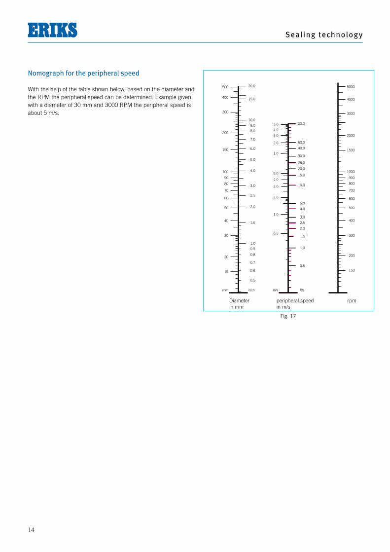
Nomograph for the peripheral speed
With the help of the table shown below, based on the diameter and the RPM the peripheral speed can be determined. Example given: with a diameter of 30 mm and 3000 RPM the peripheral speed is about 5 m/s.
mm inch
15
20
30
40
50
60
70
80
90
100
150
200
300
400
500 20.0
15.0
10.0
9.0
8.0
7.0
6.0
5.0
4.0
3.0
2.5
2.0
1.5
1.0
0.9
0.8
0.7
0.6
0.5
m/s ft/s
4.0
5.0
0.5
1.0
2.0
3.0
4.0
5.0
1.0
2.0
3.0
25.0
15.0
10.0
40.0
30.0
100.0
50.0
20.0
5.0
4.0
3.0
2.5
2.0
1.5
1.0
0.5
5000
4000
3000
2000
1500
1000
800
600
900
700
500
400
300
200
150
Diameter peripheral speed rpm in mm in m/s
Fig. 17
V-r ings
15
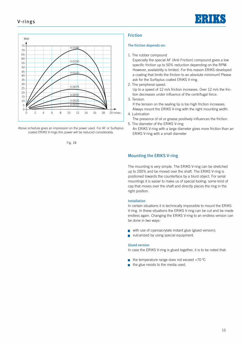
Friction The friction depends on:
1. The rubber compound Especially the special AF (Anti Friction) compound gives a low
specific friction up to 50% reduction depending on the RPM. However, availability is limited. For this reason ERIKS developed a coating that limits the friction to an absolute minimum! Please ask for the Surfaplus coated ERIKS V-ring.
2. The peripheral speed. Up to a speed of 12 m/s friction increases. Over 12 m/s the fric-
tion decreases under influence of the centrifugal force.3. Tension. If the tension on the sealing lip is too high friction increases.
Always mount the ERIKS V-ring with the right mounting width.4. Lubrication The presence of oil or grease positively influences the friction.5. The diameter of the ERIKS V-ring An ERIKS V-ring with a large diameter gives more friction than an
ERIKS V-ring with a small diameter
Mounting the ERIKS V-ring
The mounting is very simple. The ERIKS V-ring can be stretched up to 200% and be moved over the shaft. The ERIKS V-ring is positioned towards the counterface by a blunt object. For serial mountings it is easier to make us of special tooling: some kind of cap that moves over the shaft and directly places the ring in the right position.
InstallationIn certain situations it is technically impossible to mount the ERIKS V-ring. In these situations the ERIKS V-ring can be cut and be made endless again. Changing the ERIKS V-ring to an endless version can be done in two ways:
J with use of cyanoacrylate instant glue (glued version); J vulcanized by using special equipment.
Glued versionIn case the ERIKS V-ring is glued together, it is to be noted that:
J the temperature range does not exceed +70 ºC J the glue resists to the media used.
0 2 4 6 8 10 12 14 16 18 20 m/sec.
75
70
6560
55
50
4540
35
30
25
2015
10
50
Watt
V-0190
V-0150
V-0120
V-0075
V-0050
V-0025V-0010
Above schedule gives an impression on the power used. For AF or Surfaplus coated ERIKS V-rings this power will be reduced considerably.
Fig. 18


www.eriks.comwww.eriks.info
ERIKS Europe
ERIKS bvToermalijnstraat 51812 RL AlkmaarThe Netherlands Postbus 2801800 BK AlkmaarThe Netherlands T +31 (0)72 514 15 14F +31 (0)72 515 56 45E [email protected] website www.eriks.nl
ERIKS nvBoombekelaan 3 Hoboken 2660BelgiumT +32 (0) 3.829.2611F +32 (0) 3.828.3959E [email protected]
ERIKS Sealing Technolgy UKUnit 5 Yorks Park Dudley West MidlandsT U.K. +44 (0)121 508 6008F +44 (0)121 508 6009E [email protected] www.eriks.co.uk Pioneer Weston206 Cavendish PlaceWA3 6WU Birchwood ParkWarrington, CheshireUnited Kingdom T +44 1925 853 000F +44 1925 853 030 E [email protected]
ERIKS GmbH Division DichtungstechnikBrönninghauser Straße 3833729 BielefeldGermany T +49 (0) 521 / 9399-0F +49 (0) 521 / 9399-49E [email protected] www.eriks.de Passerotti sp. z o.o.ul. Spoldzielcow 94A43 - 303 Bielsko - BialaPoland T + 48 33 499 77 00 F + 48 33 499 77 17E [email protected]
ERIKS sas52, Avenue des Frères-Lumière78190 TrappesFranceB.P. 15178196 Trappes-CédexT France +33 (0) 13.482.1000F +33 (0) 13.482.1020E [email protected] www.eriks.fr
ERIKS s.r.o BratislavaRožnavská 1831 04 BratislavaSlovakia T +421 (0)2 4437 2895F +421 (0)2 4437 2899E [email protected]
ERIKS back Europa kaart.indd 1 25-08-2008 10:38:19
© M
its voorzien van duidelijke bronvermelding is overnam
e uit deze publicatie toegestaan. Alle rechten w
orden door ERIK
S nadrukkelijk voorbehouden. N
o part of this publication m
ay be reproduced
without clear reference to the source. A
ll rights expressly reserved by ERIK
S 84
60
47-KD
R-15
00


