ERIN “DRU” CHAPMAN Featured Work June 2011 Framing the Fox, Master’s Thesis Illustrates research, problem solving, and graphic representation AMOA Laguna Gloria Gatehouse and Studios Illustrates management of a historic structure for adaptive reuse and documentation skills St. Andrew’s Episcopal School, Nazro Hall Illustrates collaboration with designers and engineers as well as start to finish design experience W.S.E.L. Renovation + Addition Illustrates sustainable design, integration of environmental systems, and graphic representation Mortuary Studio Illustrates a comprehensive design approach from macro to micro scale Preservation Studies Illustrates research, documentation, and survey skills Milwaukee Makeover Project Illustrates project management, organizational skills, and community stewardship
Transcript
ERIN “DRU” CHAPMAN Featured Work June 2011
Framing the Fox, Master’s ThesisIllustrates research, problem solving, and graphic representation
AMOA Laguna Gloria Gatehouse and StudiosIllustrates management of a historic structure for adaptive reuse and documentation skills
St. Andrew’s Episcopal School, Nazro HallIllustrates collaboration with designers and engineers as well as start to finish design experience
W.S.E.L. Renovation + AdditionIllustrates sustainable design, integration of environmental systems, and graphic representation
Mortuary StudioIllustrates a comprehensive design approach from macro to micro scale
Preservation StudiesIllustrates research, documentation, and survey skills
Milwaukee Makeover ProjectIllustrates project management, organizational skills, and community stewardship
Framing the Fox Site: Outagamie and Brown Counties, WI Graduate Thesis Spring 2010
Little Kaukauna: rehabilitated mill
Little Chute
Kaukauna
Little Kaukauna
Despite recent heightened interest and the National Register Listing, the nine Lower Fox lock tender structures (ranging in age from turn of the century to the 1930s) are still in jeopardy. (They are mothballed, viewed as eyesores, and under appreciated or forgotten by the surrounding communities.) It is arguable that a recreational waterway can survive without such structures.
THIS THESIS IS A COUNTER STATEMENT TO THAT ARGUMENT.
This thesis proposes a master plan for the Lower Fox as well as focuses on three lock tender site interventions: one suburban, one urban, and one rural. I assert optimistically that, though the history of the Lower Fox River is compelling, its livelihood has not yet peaked (therefore we are not discussing a renaissance but a period of projected prosperity).
The rehabilitation of houses, sites, and structures is not proposed for preservation “itself.” These structures and sites create a memorable, unique experience. They “knit” the waterway together as a linear sequential experience (by way of their repetition and uniform, idyllic appearance) for what would otherwise be a varied episodic trip. They also “knit” the waterway to the communities and vice-versa, acting as gatekeepers.
I assert that a successful (and let’s not forget a regionally profitable) recreational waterway depends not only on the physical survival of these structures and nine sites, but on their development and integrated use for the waterway.”-Thesis book excerpt The following four pages showcases the suburban intervention at Little Chute, Wisconsin.
Little Chute: pedestrian drawbridge with residence and boat/bike exchange beyond
Kaukauna: rehabilitated lock tender residence and stable
EXISTING CONDITIONS KEYA. CIRCULATION:A1• monroe st.A2• mill st.A3• river st.A4• access roadA5• doyle park parking lotA6• sanitorium roadA7• access road
B. CONTRIBUTING RESOURCES:B1• dam, b. 1933B2• guard lock, b. 1885B3• guard lock shelter, b. ?B4• canal bridge, b. 1928B5• lock tender residence, b. 1909B6• lock 2, b. 1880B7• lock 2 waste weir, b. 1880B8• canal, b. 1853-1856B9• dam, b. ?B10• combined locks, b.1874-1877B11• lock shelter, b. circa 1917B12• combined locks waste weir, b. 1874-1877B13• lock tender residence, b. 1910
C. NON-CONTRIBUTING RESOURC-ES:(built after the period of significance)C1• garage, b. 1981C2• storage building, b. 1981C3• lock shelter, b. 1967C4• sanitary building, b. 1976C5• storage building, b. 1980?C6• garage, b. 1977
D. VIEWS & VISTASD1• unobstructed river viewD2• unobstructed river viewD3• unobstructed river viewD4• unobstructed canal viewD5• unobstructed river view
E. LAND USEE1• public parkE2• mixed useE3• residentialE4• waterway resource/infrastructureE5• industry
•information provided by HAER surveys
B5• guard lock/ lock 2 residence, b. 1909. HAER photo
B10• combined locks, b. 1874-77. HAER photo
B8• combined locks lock shelter, b. 1917. HAER photo
B13• combined locks residence, b. 1910. HAER photo
SITE PHOTOS
0’ 500’
250’
B1
D1B3B2 B4
D4A3
A1 E2
E2
A2
B5E4C1
C2A4
E1IslandPark
DoylePark
D2
E3
E3
E3
E3
E5
E5
E3
E3
E1
E4
E3
E4C3 C4
B6B7
D3
B8
B9
A5E1
B11B13B10
D5
A6
C5 C6
HeesakkerPark
LITTLE CHUTE EXISTING CONDITIONS PLAN
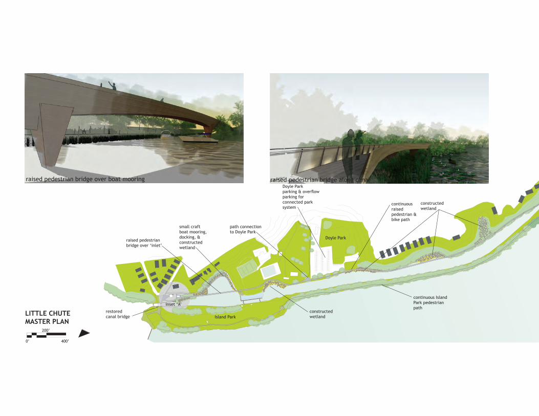
Doyle Parkparking & overflow parking for connected parksystem
path connectionto Doyle Park
small craftboat mooring,docking, &constructedwetland
raised pedestrianbridge over ‘inlet’
restoredcanal bridge
constructedwetland
inset ‘A’
Doyle Park
Island Park
continuousraisedpedestrian &bike path
continuous IslandPark pedestrianpath
constructed wetland
0’ 400’
200’
LITTLE CHUTEMASTER PLAN
raised pedestrian bridge over boat mooring raised pedestrian bridge along canal
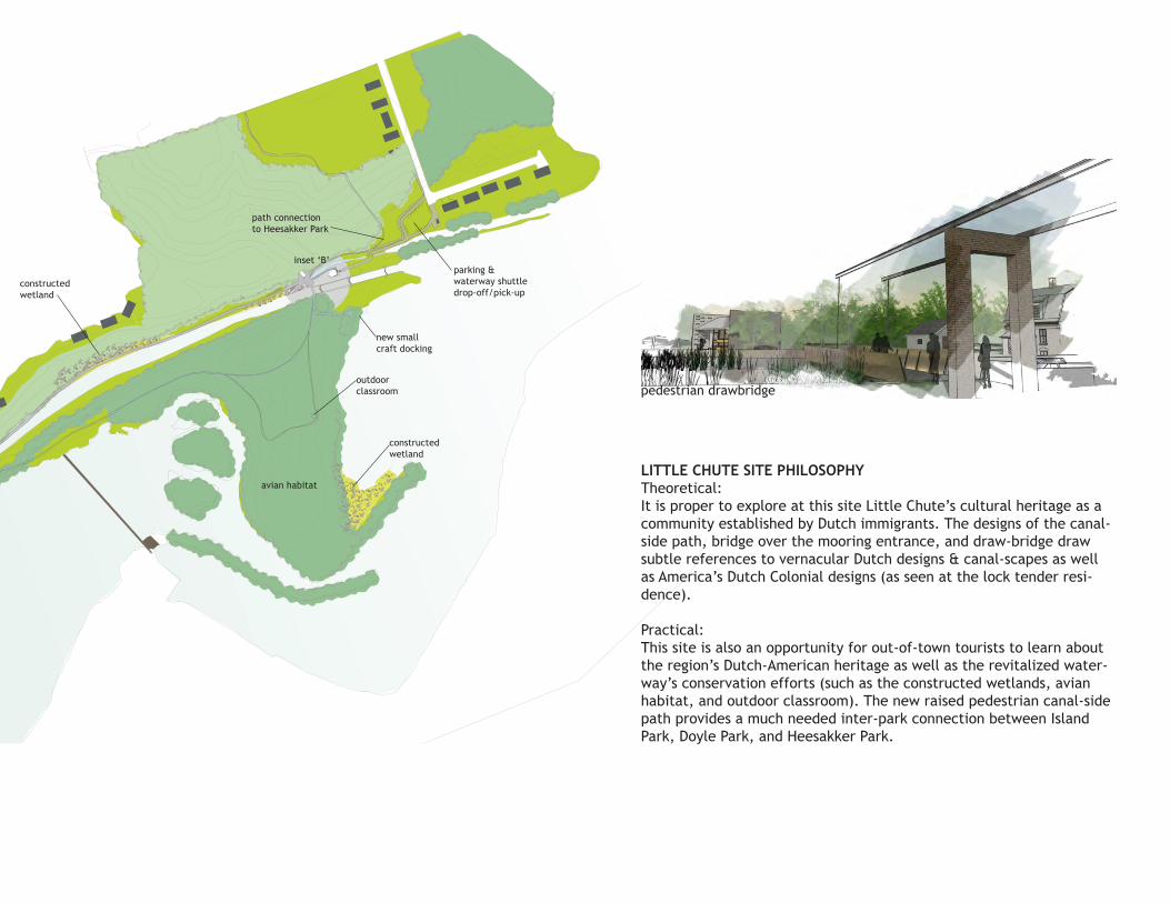
parking &waterway shuttledrop-off/pick-up
inset ‘B’
avian habitat
outdoorclassroom
constructed wetland
constructed wetland
path connectionto Heesakker Park
new small craft docking
LITTLE CHUTE SITE PHILOSOPHY Theoretical: It is proper to explore at this site Little Chute’s cultural heritage as a community established by Dutch immigrants. The designs of the canal-side path, bridge over the mooring entrance, and draw-bridge draw subtle references to vernacular Dutch designs & canal-scapes as well as America’s Dutch Colonial designs (as seen at the lock tender resi-dence).
Practical: This site is also an opportunity for out-of-town tourists to learn about the region’s Dutch-American heritage as well as the revitalized water-way’s conservation efforts (such as the constructed wetlands, avian habitat, and outdoor classroom). The new raised pedestrian canal-side path provides a much needed inter-park connection between Island Park, Doyle Park, and Heesakker Park.
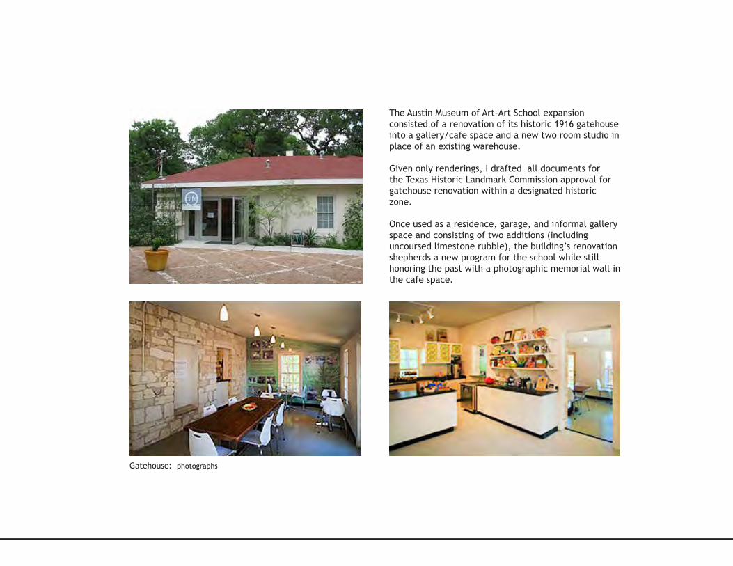
The Austin Museum of Art-Art School expansion consisted of a renovation of its historic 1916 gatehouse into a gallery/cafe space and a new two room studio in place of an existing warehouse.
Given only renderings, I drafted all documents for the Texas Historic Landmark Commission approval for gatehouse renovation within a designated historic zone.
Once used as a residence, garage, and informal gallery space and consisting of two additions (including uncoursed limestone rubble), the building’s renovation shepherds a new program for the school while still honoring the past with a photographic memorial wall in the cafe space.
Gatehouse: photographs
The new studio is comprised of a pottery space and a painting space. The clerestory windows provide natural ambient light befitting a painting space, and consultant coordination ensured proper installed artificial light for evening classes.
As I drafted all studio documents, I learned the methodology of wood-framed construction and how to integrate prefabricated materials into a design for cost-effectiveness. Exposed laminated veneer lumber provides a warmth to the desired bare-bones aesthetic.
Studios: photographs of exterior, interior (painting), and building section
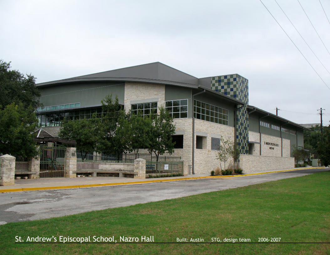
St. Andrew’s Episcopal School, Nazro Hall Built: Austin STG, design team 2006-2007
Working directly under the project manager from schematic design through construction, I researched and developed the spaces, building facades, and building envelope of this middle school gymnasium as well as coordinated all gymnasium and kitchen equipment. Nazro Hall connects to an older gymnasium along its western edge via a covered walkway and an interior entrance.
Structural integrity is emphasized with a series of bowstring trusses that define the gym’s interior. Natural light converses with color adding playfulness to the space.
I was the go-to contact for all engineering consultants and the general contractor during construction administration. Though sometimes tedious, c.a. is a rewarding process; from idea to documentation to shop drawings, I gained an intimate understanding of Nazro Hall at all scales.
St. Andrew’s Episcopal School, Nazro Hall Built: Austin STG, design team 2006-2007
Gymnasium interior: photographs and plan
Exterior deck guardrail: photograph and details
W.S.E.L. Renovation + Addition Site: UW Madison Studio 825, Professor Wasley Spring 2009
INTERIOR PERSPECTIVE: GENERAL LAB ON THIRD FLOOR HYDRAULICS LAB
UW Madison’s Water Sciences & Engineering Laboratory (W.S.E.L.), home to both water and air quality research, is currently located in a historic 40,000 square foot structure directly next to Lake Mendota in close proximity to the iconic Union building. This comprehensive studio’s objective was to use carbon neutral design principles and LEED platinum design standards towards both an intense renovation of the existing building and an office addition.
Through communication and workshops with the actual users of the building, a program was established. The main ‘parti’ of my design was preservation of the historic lakefront facade with exploitation of the back southern facade, which was redesigned to maximize daylighting opportunities while expanding much needed circulation space.
A considerable portion of this studio was given to the integration of mechanical systems. The result of such considerations is a stronger and more feasible design. For example, the new vertical supply air shafts in the existing structure created a design element which was then continued into the adjacent addition. The new addition space was an opportunity to create an entirely carbon neutral structure. Some of its features include raised floor plenums, a cistern, and full daylighting capabilities.
INTERIOR PERSPECTIVE: DATA ACQUISITION LAB IN PUMP HOUSE AT NIGHT INTERIOR PERSPECTIVE: OPEN GRADUATE OFFICE IN ADDITION DURING THE DAY, SHOW-ING DAYLIGHTING CAPABILITIES
SOUTH FACADE BUILDING SECTION: SHOWCASES NEW VERTICAL SUPPLY AIR SHAFT(S)
PROGRAM KEY PLANPUBLIC SPACES: SEA GRANT, LECTURE
LAB & PILOT SPACES
OFFICE & ADMINISTRATIVE SPACES
SERVICE & CIRCULATION
BASEMENT FLOOR PLAN 1/32”=1’-0”
SECOND FLOOR PLAN 1/32”=1’-0”
THIRD FLOOR PLAN 1/32”=1’-0”
ADDITION VENTILATION DIAGRAM VERTICAL SHAFTS AS SUPPLY & STALE AIR PLENUM, SUPPLY AIR RELEASED INTO RAISED FLOOR PLENUM SPACES
RENOVATED W.S.E.L. VENTILATION DIAGRAM AT CIRCULATION CORRIDOR SUPPLY AIR DIRECTED TO VERTICAL SHAFTS & TO DUCTWORK AT FLOOR LEVEL LOCATIONS, RESULTING IN DISPACEMENT VENTILATION
EXISTING/RENOVATED
W.S.E.L.
ADDITION
1
2a
2b
3a
3b
4a
4b
4c
5
67
AHU
AHU
8
9 10
11
MECHANICAL SYSTEMS DIAGRAMEXISTING/RENOVATED BUILDING 1.FRESH AIR TO AHU
2a.SUPPLY AIR TO VERTICAL CORRIDOR SHAFTS
2b.SUPPLY AIR TO ALL FLOORS
3a.SUPPLY AIR IN VERTICAL SHAFTS TO CORRIDORS VIA DISPACEMENT VENTILATION
3b.SUPPLY AIR TO LAB SPACES VIA DISPLACEMENT VENTILATION IN CASEWORK
4a.STALE AIR RETREIVED VIA FUME HOODS
4c.STALE AIR COLLECTION FROM PLENUMS TO VERTICAL SHAFT IN TANK HOUSE
5.HEAT RECOVERY
6.EXHAUST VIA ROOFTOP FANS IN NEW SOUTH TOWER
ADDITION 7.FRESH AIR TO AHU VIA PARTIALLY EXTERIOR VERTICAL SHAFT
8.SUPPLY AIR TO FLOORS VIA DUCTWORK IN VERTICAL SHAFTS
9.SUPPLY AIR RELEASED INTO RAISED FLOOR PLENUM SPACE
10.STALE AIR COLLECTED IN OPEN PLENUM SPACE OF VERTICAL SHAFTS
11.STALE AIR EXHAUSTED ABOVE ROOF VIA SUNKEN EXHAUST FANS IN VERTICAL SHAFTS
RENOVATED W.S.E.L. DAYLIGHTING DIAGRAM AT CIRCULATION CORRIDOR
14
BUILDING CYCLE • presented on 11.20.2009BUILDING CYCLE • presented on 11.20.2009p
fritted glass louveredwindow sys-tem for stack ventilation
acousticperforatedmetal panels, acousticwoolen batts, & z clip wall system
metal joists @ 3’ o.c.
refl ective t.p.o. roofi ng
dropped gy. bd. ceiling
continuousperimeter cove lighting
wooden divider screen
vvventilaationv
R E V I S E D S I T E P L A N : 1:200
M O R T U A R Y C O M P L E X b u i l d i n g c y c l ee r i n d r u c h a p m a n 1 1 . 2 0 . 0 9
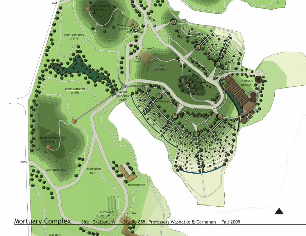
Mortuary Complex Site: Grafton, WI Studio 885, Professors Washatko & Carnahan Fall 2009
This studio required philosophical thought from the macro scale (a sixty acre cemetery site) down to the micro scale (a crematorium room within a funeral services complex). From site to building to room, I created my own patterns, based on Christopher Alexander’s Pattern Language, which created a unity and cohesiveness between all scales. The site plan incorporated an interpretive center, green burial and traditional burial plots, several mausoleums, two chapels, and a mortuary complex, my building of choice for further investigation.
An overarching theme is the pattern profane to sacred design hierarchy, which manifests itself through path progression rather than simply in the plan’s form. This hierarchy allows visitors to make conscious choice’s with progression through the site.
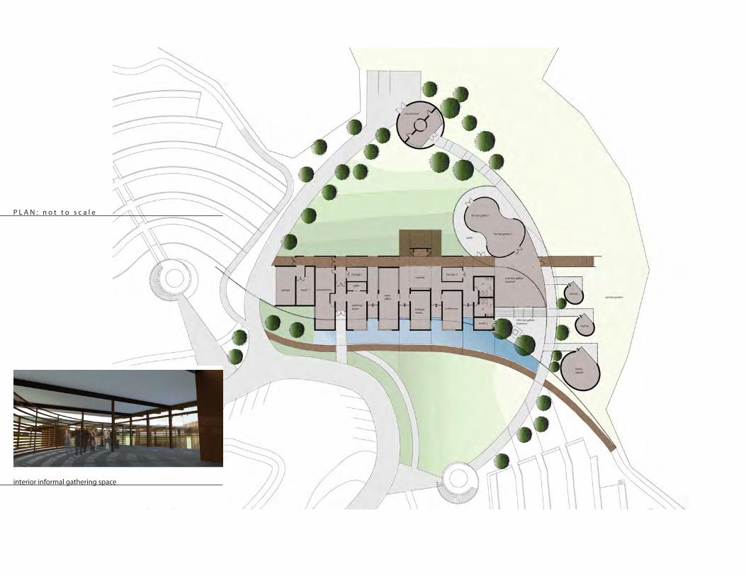
Not unsimilar to the overall site plan, the progression through the building, as one goes from profane to sacred, becomes a conscious act of awareness for the visitor. The visitor chooses their progression through the building. Exits are offered prior to reaching the sacred spaces (gathering, family repose, crematorium, etc.).
The division of space, between the profane & the sacred, also extends out beyond the building into site integration, with the business entities privileged with views out to a public garden, & the repose entities situated next to a private garden, behind the “privacy screen.” This wooden divider screen (or “ribbon”) acts as a privacy screen between the general cemetery public & those visiting the mortuary complex for a viewing or a funeral. The materials chosen & overall building forms derive from my philosophy that plutonic forms transcend above all cultures & speak to the primal & ancient shared collective subconsciousness.
northeast elevation
west elevation
looking at repose spaces from the private gardenP E R S P E C T I V E S
public facade with mausoleum in the distance (relationship to cemetery)
exterior informal gathering space
system of wholes
profane path
sacred path
public viewsout & in
private viewsout & in
center-piece
focus
focus
fo-
center-piece
a traditional funeral or memorial layout
an untraditional, more in-formal funeral or memorial layout
B U I L D I N G P A T T E R N Snested wholeness one building, two paths private versus exposed views a variety of focal points
1/16”=1’-0”F L O O R P L A N :
P L A N : n o t t o s c a l e
interior informal gathering space
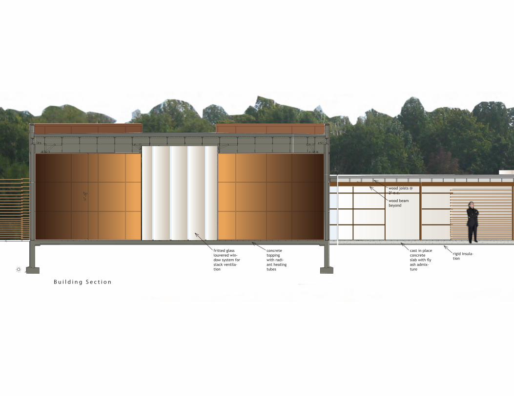
cast in place concrete slab with fly ash admix-ture
concrete topping with radi-ant heating tubes
fritted glass louvered win-dow system for stack ventila-tion
wood beam beyond
wood joists @ 2’ o.c.
rigid insula-tion
B u i l d i n g S e c t i o n
wooden divider
sliding glass doors
repose roombeyond
reflection pool
wooden divider screen
Preservation Studies UWM 2008-2010
3D documentation model
survey documentation
Preservation Studies UWM 2008-2010
The Certificate in Preservation Studies afforded me the opportunity to gain research, documentation, and survey skills as well as the theoretical framework regarding preserving aging buildings in a modern environment. Summer studies in Italy provided a hands-on experience with masonry and mortar restoration as well as historic and modern survey techniques.
The certificate mirrors my desire to bring historical context to design as well as my passion for adaptive reuse.
H o l t o n H a l l , b . 1 8 9 2 , U W Mexisting conditions1978 remodel documents
C h u r c h o f S a n t o G e m i n i e , b . 8 0 0 - 1 9 0 0 A . D . , U m b r i a
facade before restorationfacade deteriorationsurvey documentation personal facade restoration work
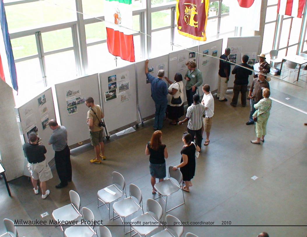
The Milwaukee Makeover Project is a partnership effort by the Milwaukee Healthy Neighborhoods Initiative (HNI), NIDC, partici-pating lenders, and architects to connect design professionals to homeowners and promote high quality exterior improvements.
This is a unique effort aimed at modest Milwaukee homes, many built in the 1950s and 1960s that while serviceable, often lack visual appeal. By encouraging strong design and high quality stan-dard setting improvements, HNI hopes to stimulate greater rein-vestment by additional homeowners as they seek to improve their homes.
The vision of the Milwaukee Makeover Project is to achieve high quality exterior property improvements – work visible from the street - that come out of a design consultation with an architect or designer.
As the sole dedicated employee to the project, still in its infancy, I was tasked with managing the project and providing the template for its future rounds.
I recruited both designers and clients, acted as liason with city representatives, and spoke with media. I planned and organized the project’s first design charrette.
Designer & Client Charrette: photographs courtesy of Todd Montgomery
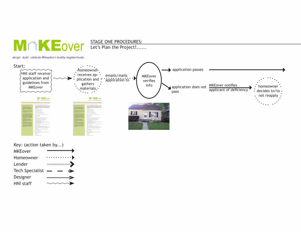
STAGE ONE PROCEDURES: Let’s Plan the Project!......
Key: (action taken by...)MKEoverHomeownerLenderTech SpecialistDesignerHNI staff
homeownerreceives ap-plication and
gathersmaterials
HNI staff receive application and guidelines from
MKEover
emails/mailsapplication to
MKEoververifies
info
application passes
homeownerdecides to/to not reapply
application does not pass
MKEover notifiesapplicant of deficiency
Start:
Healthy Designs for Healthy Neighborhoods
What is the Healthy Neighborhoods Initiative?
Comprised of nine Milwaukee neighborhoods where it makes fi nancial and emotional “sense” for investment, the Healthy Neighborhoods Initiative promotes investment as well as community leadership with local homeowners, businesses, and institutions by focusing on each neighborhood’s positive attributes.
The HNI concentrates on:
• promoting neighborhood identity;
• improving physical conditions;
• promoting a viable real estate market;
• and fostering neighborhood management.
How does this translate into healthy design for the Milwaukee Makeover Project?• Help participating homeowners to feel
and be secure in their homes while at the same time not “turning their backs” to their neighborhood. For example, we advocate fi nding to the common security door with bars.
• Consider other security items such as porch and property lighting, and discuss them with your homeowner should they have concerns regarding security.
• Check if accessibility issues are a concern.
• Go ahead and get innovative! The homeowner may have a set design in mind, or they may be more open to suggestions. If they are, don’t be afraid to think outside the box. The homeowners value your donated time and want to get as much out of it as possible. Do remember, however, to gauge their budget and keep that in mind as you move forward with your design.
• Consider the historical character of the house and the historical context of the neighborhood. Does this play into your design? Is the house’s character important to the homeowner?
• Think not just how you can “clean up” or simply repair the property’s appearance but also think about what design elements you can incorporate to enhance the property.
• Consider calling-out more environmentally -sensitive materials and sustainable design features, such as rain barrels. You may want to discuss these at the site visit with the homeowner.
What can my design as a MKEover Designer address?• Replacement of siding;
• New window installation;
• Painting;
• Repair or replace cement walkways approaching the property;
• Roofi ng, including roofi ng system over entry door;
• Front porch improvements, including stairs and railings;
• Decorative lighting for porch and front yard;
• New awnings and or shutters
• Quality exterior doors and screen/storm doors (installation of metal or iron security doors is not recommended);
• Removal of chain link fences;
• Permanent landscaping such as shrubs, hedges, trees, and perennial plants;
• Repair of retaining walls;
• Replacement of gutters and installation of gutter guards;
• Decorative crown molding around doors, windows, eaves and soffi ts;
• Installation of fl ower boxes with matching crown molding to the house;
• Appropriate house numbers, mailboxes, and door hardware;
• Accessibility ramps.
Note: this is not an exhaustive list.
The following ineligible items include but are not limited to:• Lawn/porch furniture;
• Flower pots;
• Door bells;
• Ornamental garden elements.
MKEover pairs hom-eowner w/ design team
homeowner given 5 business days
to contact design team and schedule
site visit
MKEover teamsite visit at respective
house
Design teamproduces
24x36 plot
N
provides copyand digital
file to MKEover
invites MKE-over
teams, HNI staff, GMF, media, etc.
to event
presentation to homeowners (dis-cussion, display,
celebration)
MKEoverAr-ranges pre-sentation to homeown-ers when enough