Erosion Prevention & Sediment Control Field Handbook For small scale utility projects Hamilton County, Ohio The Hamilton County Soil and Water Conservation District The Metropolitan Sewer District of Greater Cincinnati
For small scale utility projectsHamilton County, Ohio
The Hamilton County Soil and Water Conservation District
The Metropolitan Sewer Districtof Greater Cincinnati
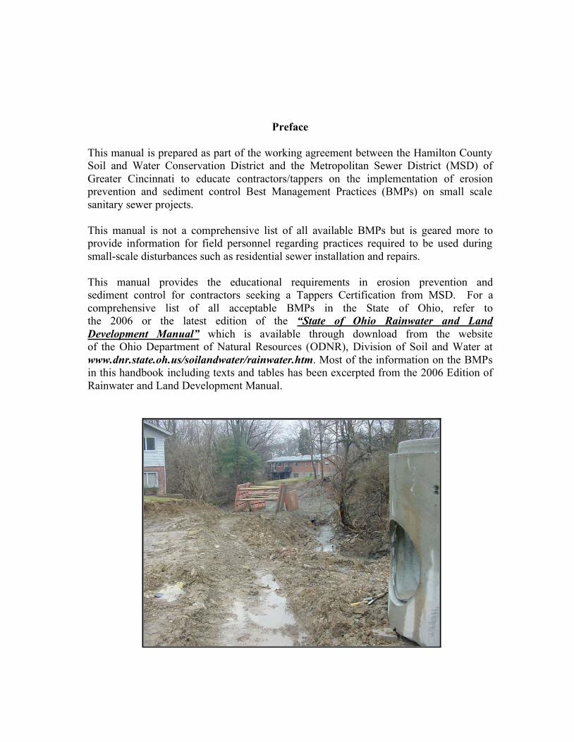
Preface
This manual is prepared as part of the working agreement between the Hamilton County
Soil and Water Conservation District and the Metropolitan Sewer District (MSD) of
Greater Cincinnati to educate contractors/tappers on the implementation of erosion
prevention and sediment control Best Management Practices (BMPs) on small scale
sanitary sewer projects.
This manual is not a comprehensive list of all available BMPs but is geared more to
provide information for field personnel regarding practices required to be used during
small-scale disturbances such as residential sewer installation and repairs.
This manual provides the educational requirements in erosion prevention and
sediment control for contractors seeking a Tappers Certification from MSD. For a
comprehensive list of all acceptable BMPs in the State of Ohio, refer to
the 2006 or the latest edition of the “State of Ohio Rainwater and Land
Development Manual” which is available through download from the website
of the Ohio Department of Natural Resources (ODNR), Division of Soil and Water at
www.dnr.state.oh.us/soilandwater/rainwater.htm. Most of the information on the BMPs
in this handbook including texts and tables has been excerpted from the 2006 Edition of
Rainwater and Land Development Manual.
Erosion Prevention and Sediment Control Field Handbook
TABLE OF CONTENTS
Page
I) INTRODUCTION 1
a) Impacts of erosion and sedimentation
II) AREAS OF SPECIAL CONCERN 3
III) SEDIMENT CONTROL PRACTICES 4
a) Silt fence
b) Super silt fence
c) Mulch/woodchip berms
d) Inlet protection
IV) EROSION PREVENTION PRACTICES 19
a) Permanent Seeding
b) Matting/Soil blankets
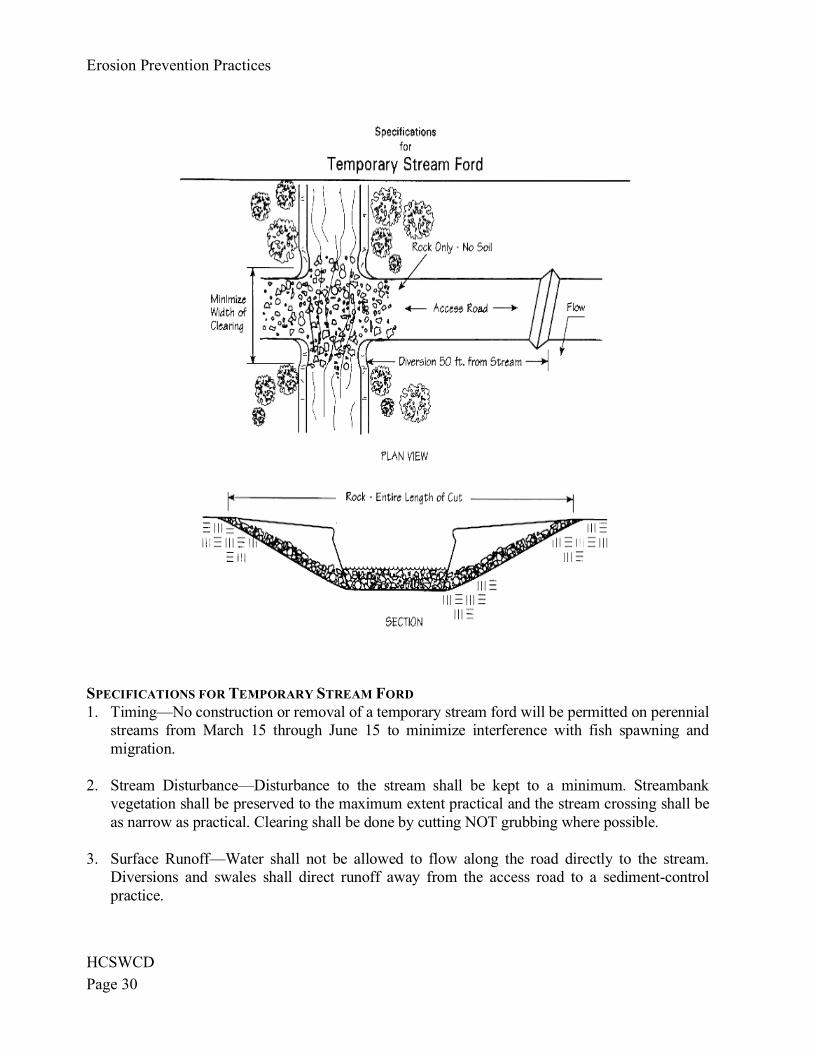
c) Stream Crossing
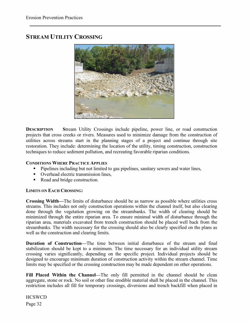
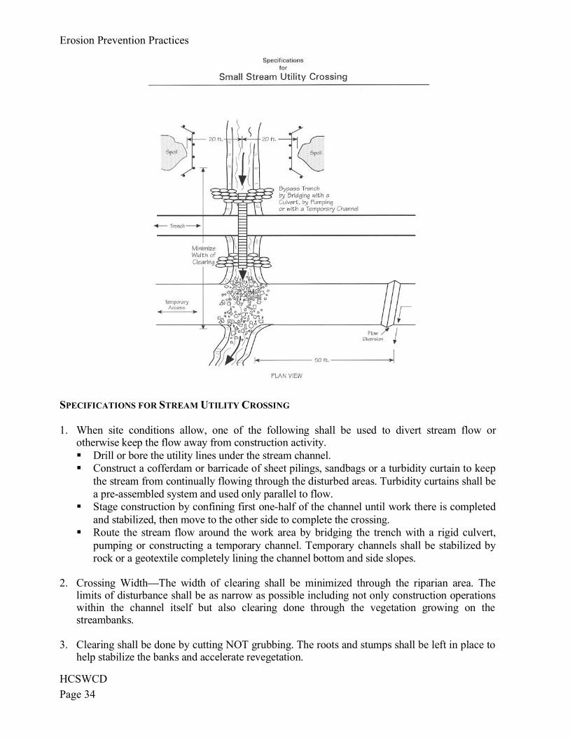
d) Stream Utility Crossing
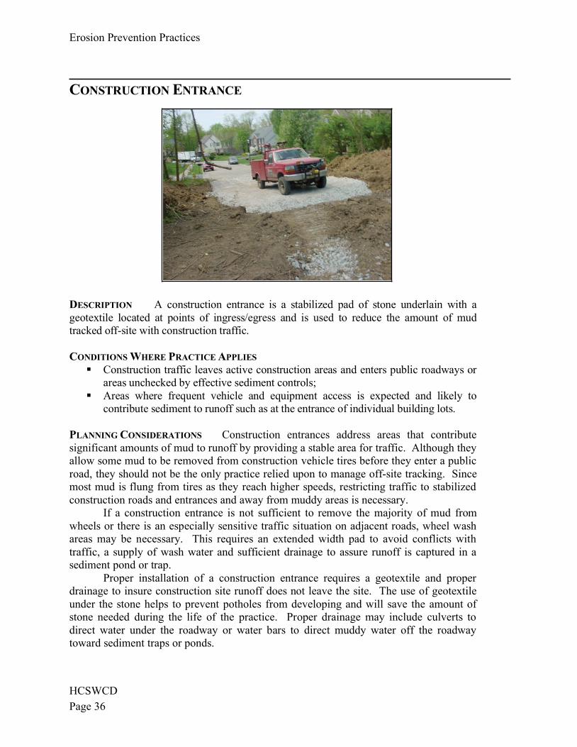
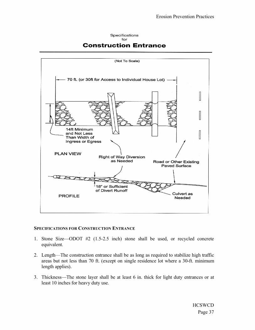
e) Construction Entrance
V) AGENCY CONTACTS 39
Compiled by the Hamilton County Soil and Water Conservation District, (513) 772-7645. All District
programs are offered on a nondiscriminatory basis without regard to race, color, national origin, religion,
sex, age, marital status or handicap.
Preface
This manual is prepared as part of the working agreement between the Hamilton County
Soil and Water Conservation District and the Metropolitan Sewer District (MSD) of
Greater Cincinnati to educate contractors/tappers on the implementation of erosion
prevention and sediment control Best Management Practices (BMPs) on small scale
sanitary sewer projects.
This manual is not a comprehensive list of all available BMPs but is geared more to
provide information for field personnel regarding practices required to be used during
small-scale disturbances such as residential sewer installation and repairs.
This manual provides the educational requirements in erosion prevention and
sediment control for contractors seeking a Tappers Certification from MSD. For a
comprehensive list of all acceptable BMPs in the State of Ohio, refer to
the 2006 or the latest edition of the “State of Ohio Rainwater and Land
Development Manual” which is available through download from the website
of the Ohio Department of Natural Resources (ODNR), Division of Soil and Water at
www.dnr.state.oh.us/soilandwater/rainwater.htm. Most of the information on the BMPs
in this handbook including texts and tables has been excerpted from the 2006 Edition of
Rainwater and Land Development Manual.
Erosion Prevention and Sediment Control Field Handbook
TABLE OF CONTENTS
Page
I) INTRODUCTION 1
a) Impacts of erosion and sedimentation
II) AREAS OF SPECIAL CONCERN 3
III) SEDIMENT CONTROL PRACTICES 4
a) Silt fence
b) Super silt fence
c) Mulch/woodchip berms
d) Inlet protection
IV) EROSION PREVENTION PRACTICES 19
a) Permanent Seeding
b) Matting/Soil blankets
c) Stream Crossing
d) Stream Utility Crossing
e) Construction Entrance
V) AGENCY CONTACTS 39
Compiled by the Hamilton County Soil and Water Conservation District, (513) 772-7645. All District
programs are offered on a nondiscriminatory basis without regard to race, color, national origin, religion,
sex, age, marital status or handicap.
HCSWCDPage 1
INTRODUCTION
Purpose
This manual provides the necessary education to MSD contractors/tappers about requiredBest Management Practices (BMPs) used in erosion prevention and sediment control andproper installation techniques and maintenance requirements to insure the controls arefunctional throughout the duration of the work. This manual is specifically gearedtowards small-scale projects disturbing less than 1 acre of ground such as utilityinstallation or repairs on existing residential or commercial buildings and/or repairs ofsmall sections of utility lines. Contractors working on capital improvements and large-scale utility installations for subdivisions or commercial developments must complete amore comprehensive training in erosion prevention and sediment control. Anyone inOhio disturbing more than 1 acre of ground for construction activities is required to havean Ohio EPA NPDES Construction Permit. Anyone within unincorporated HamiltonCounty who is disturbing land for building construction or significant clearing, filling, orgrading activities is required to obtain a Hamilton County Earthwork Permit prior tocommencing with any earth-disturbing activity. Failure to obtain an Earthwork Permitmay cause the Enforcing Official to issue Stop Work Orders. The property owner shall besubject to enforcement actions under ORC 307.79. Other permits may be required by thelocal municipality. Contact Ohio EPA and the Hamilton County Soil and WaterConservation District for more information (see Agency Contacts).
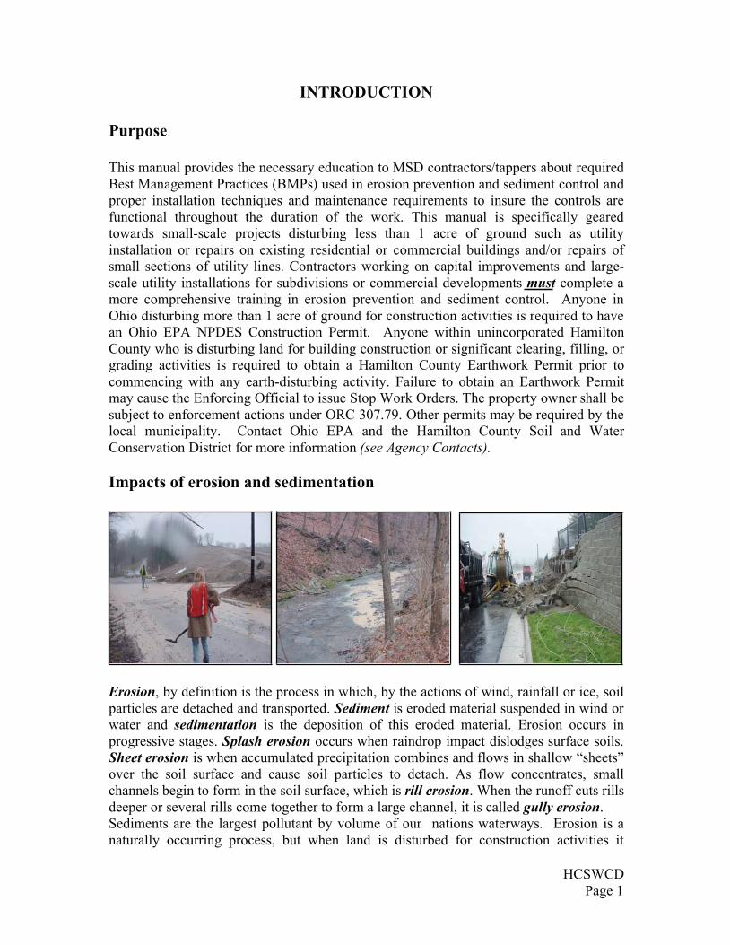
Impacts of erosion and sedimentation
Erosion, by definition is the process in which, by the actions of wind, rainfall or ice, soilparticles are detached and transported. Sediment is eroded material suspended in wind orwater and sedimentation is the deposition of this eroded material. Erosion occurs inprogressive stages. Splash erosion occurs when raindrop impact dislodges surface soils.Sheet erosion is when accumulated precipitation combines and flows in shallow “sheets”over the soil surface and cause soil particles to detach. As flow concentrates, smallchannels begin to form in the soil surface, which is rill erosion. When the runoff cuts rillsdeeper or several rills come together to form a large channel, it is called gully erosion.Sediments are the largest pollutant by volume of our nations waterways. Erosion is anaturally occurring process, but when land is disturbed for construction activities it
HCSWCDPage 1
INTRODUCTION
Purpose
This manual provides the necessary education to MSD contractors/tappers about requiredBest Management Practices (BMPs) used in erosion prevention and sediment control andproper installation techniques and maintenance requirements to insure the controls arefunctional throughout the duration of the work. This manual is specifically gearedtowards small-scale projects disturbing less than 1 acre of ground such as utilityinstallation or repairs on existing residential or commercial buildings and/or repairs ofsmall sections of utility lines. Contractors working on capital improvements and large-scale utility installations for subdivisions or commercial developments must complete amore comprehensive training in erosion prevention and sediment control. Anyone inOhio disturbing more than 1 acre of ground for construction activities is required to havean Ohio EPA NPDES Construction Permit. Anyone within unincorporated HamiltonCounty who is disturbing land for building construction or significant clearing, filling, orgrading activities is required to obtain a Hamilton County Earthwork Permit prior tocommencing with any earth-disturbing activity. Failure to obtain an Earthwork Permitmay cause the Enforcing Official to issue Stop Work Orders. The property owner shall besubject to enforcement actions under ORC 307.79. Other permits may be required by thelocal municipality. Contact Ohio EPA and the Hamilton County Soil and WaterConservation District for more information (see Agency Contacts).
Impacts of erosion and sedimentation
Erosion, by definition is the process in which, by the actions of wind, rainfall or ice, soilparticles are detached and transported. Sediment is eroded material suspended in wind orwater and sedimentation is the deposition of this eroded material. Erosion occurs inprogressive stages. Splash erosion occurs when raindrop impact dislodges surface soils.Sheet erosion is when accumulated precipitation combines and flows in shallow “sheets”over the soil surface and cause soil particles to detach. As flow concentrates, smallchannels begin to form in the soil surface, which is rill erosion. When the runoff cuts rillsdeeper or several rills come together to form a large channel, it is called gully erosion.Sediments are the largest pollutant by volume of our nations waterways. Erosion is anaturally occurring process, but when land is disturbed for construction activities it
Introduction
HCSWCDPage 2
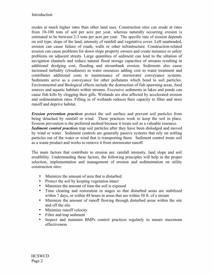
erodes at much higher rates than other land uses. Construction sites can erode at ratesfrom 10-100 tons of soil per acre per year, whereas naturally occurring erosion isestimated to be between 2-3 tons per acre per year. The specific rate of erosion dependson soil type, slope of the land, intensity of rainfall and vegetative cover. Left unattended,erosion can cause failure of roads, walls or other infrastructure. Construction-relatederosion can cause problems for down slope property owners and create nuisance or safetyproblems on adjacent streets. Large quantities of sediment can lead to the siltation ofnavigation channels and reduce natural flood storage capacities of streams resulting inadditional dredging cost, flooding and streambank erosion. Sediments also causeincreased turbidity (cloudiness) in water resources adding cost to water treatment andcontributes additional costs to maintenance of stormwater conveyance systems.Sediments serve as a conveyance for other pollutants which bond to soil particles.Environmental and Biological effects include the destruction of fish spawning areas, foodsources and aquatic habitats within streams. Excessive sediments in lakes and ponds cancause fish kills by clogging their gills. Wetlands are also affected by accelerated erosionand sedimentation rates. Filling in of wetlands reduces their capacity to filter and storerunoff and deprive habitat.
Erosion prevention practices protect the soil surface and prevent soil particles frombeing detached by rainfall or wind. These practices work to keep the soil in place.Erosion prevention is the preferred method because it treats soil as a valuable resource.Sediment control practices trap soil particles after they have been dislodged and movedby wind or water. Sediment controls are generally passive systems that rely on settlingparticles out of the water or wind that is transporting them. Sediment control treats soilas a waste product and works to remove it from stormwater runoff.
The main factors that contribute to erosion are: rainfall intensity, land slope and soilerodibility. Understanding these factors, the following principles will help in the properselection, implementation and management of erosion and sedimentation on utilityconstruction sites:
• Minimize the amount of area that is disturbed• Protect the soil by keeping vegetation intact• Minimize the amount of time the soil is exposed• Time clearing and restoration in stages so that disturbed areas are stabilized
within 7 days, or within 48 hours in areas that are within 50 ft. of a stream• Minimize the amount of runoff flowing through disturbed areas within the site
and off the site• Minimize runoff velocity• Filter and trap sediment• Inspect and maintain BMPs control practices regularly to ensure maximum
effectiveness
HCSWCDPage 3
AREAS OF SPECIAL CONCERN
Hillsides—Areas with steep slopes are of special concern due to increased runoffvelocity which increases erosion and off-site sedimentation. Slopes tend to be steepersurrounding receiving streams or roads. Special care should be taken to reduce potentialimpacts to adjacent properties, public infrastructure or water resources from erosion,sedimentation or landslides. In Hamilton County, approximately 28% of the land hasslopes steeper than 15% and are prone to slippage; we also have some of the mosterodible soils in the state.
Streams and Riparian Areas—Areas directly surrounding a stream system provide manystormwater benefits, not the least of which is making water cleaner. Water is treated as itflows across a buffer and enters a stream. The water quality of the stream is improved byforested riparian areas. Other benefits include a self-maintaining drainage system, floodstorage, groundwater recharge and a complex interaction of aquatic habitats.
The benefits provided by riparian areas are easily lost if they are not recognized.Deliberate protection is required to prevent encroachment, which includes clearing trees,filling, channel modification and at its most extreme, replacing the channel with anenclosed drainage system. A fundamental method for improving stormwater quality is todevise ways of avoiding encroachment upon riparian areas and to preserve these criticalparts of the landscape as designated open space. Whenever possible, native materialsshould be used and the use of concrete and riprap should be minimized. Any disturbancewithin these areas shall be stabilized immediately after construction activities arecompleted. Impacts to streams for utility construction are regulated by the US Army Corpsof Engineers; see Agency Contacts. Failure to obtain necessary permits will subject theowner to enforcement actions.
Floodplain—Any construction work conducted in a floodplain is regulated by theFederal Emergency Management Agency. Many jurisdictions, including HamiltonCounty, administer the floodplain regulations.
A floodplain is the lowland adjacent to a river, lake or ocean. Floodplains aredesignated by the frequency of the flood that is large enough to cover them. Floodfrequency is the chance of occurrence in a given year, which is the percentage of theprobability of flooding each year. For example, the 100-year flood has a 1% chance ofoccurring in any given year. Most of the known floodplains in the U.S. have beenmapped by the Flood Insurance Administration, part of the Federal EmergencyManagement Agency. These maps are available for viewing at the Hamilton County Soiland Water Conservation District; see Agency Contacts.
Check with local jurisdiction for specific questions about floodplains or inunincorporated Hamilton County, call the Department of Public Works at(513) 946-4750.
Introduction
HCSWCDPage 2
erodes at much higher rates than other land uses. Construction sites can erode at ratesfrom 10-100 tons of soil per acre per year, whereas naturally occurring erosion isestimated to be between 2-3 tons per acre per year. The specific rate of erosion dependson soil type, slope of the land, intensity of rainfall and vegetative cover. Left unattended,erosion can cause failure of roads, walls or other infrastructure. Construction-relatederosion can cause problems for down slope property owners and create nuisance or safetyproblems on adjacent streets. Large quantities of sediment can lead to the siltation ofnavigation channels and reduce natural flood storage capacities of streams resulting inadditional dredging cost, flooding and streambank erosion. Sediments also causeincreased turbidity (cloudiness) in water resources adding cost to water treatment andcontributes additional costs to maintenance of stormwater conveyance systems.Sediments serve as a conveyance for other pollutants which bond to soil particles.Environmental and Biological effects include the destruction of fish spawning areas, foodsources and aquatic habitats within streams. Excessive sediments in lakes and ponds cancause fish kills by clogging their gills. Wetlands are also affected by accelerated erosionand sedimentation rates. Filling in of wetlands reduces their capacity to filter and storerunoff and deprive habitat.
Erosion prevention practices protect the soil surface and prevent soil particles frombeing detached by rainfall or wind. These practices work to keep the soil in place.Erosion prevention is the preferred method because it treats soil as a valuable resource.Sediment control practices trap soil particles after they have been dislodged and movedby wind or water. Sediment controls are generally passive systems that rely on settlingparticles out of the water or wind that is transporting them. Sediment control treats soilas a waste product and works to remove it from stormwater runoff.
The main factors that contribute to erosion are: rainfall intensity, land slope and soilerodibility. Understanding these factors, the following principles will help in the properselection, implementation and management of erosion and sedimentation on utilityconstruction sites:
• Minimize the amount of area that is disturbed• Protect the soil by keeping vegetation intact• Minimize the amount of time the soil is exposed• Time clearing and restoration in stages so that disturbed areas are stabilized
within 7 days, or within 48 hours in areas that are within 50 ft. of a stream• Minimize the amount of runoff flowing through disturbed areas within the site
and off the site• Minimize runoff velocity• Filter and trap sediment• Inspect and maintain BMPs control practices regularly to ensure maximum
effectiveness
HCSWCDPage 3
AREAS OF SPECIAL CONCERN
Hillsides—Areas with steep slopes are of special concern due to increased runoffvelocity which increases erosion and off-site sedimentation. Slopes tend to be steepersurrounding receiving streams or roads. Special care should be taken to reduce potentialimpacts to adjacent properties, public infrastructure or water resources from erosion,sedimentation or landslides. In Hamilton County, approximately 28% of the land hasslopes steeper than 15% and are prone to slippage; we also have some of the mosterodible soils in the state.
Streams and Riparian Areas—Areas directly surrounding a stream system provide manystormwater benefits, not the least of which is making water cleaner. Water is treated as itflows across a buffer and enters a stream. The water quality of the stream is improved byforested riparian areas. Other benefits include a self-maintaining drainage system, floodstorage, groundwater recharge and a complex interaction of aquatic habitats.
The benefits provided by riparian areas are easily lost if they are not recognized.Deliberate protection is required to prevent encroachment, which includes clearing trees,filling, channel modification and at its most extreme, replacing the channel with anenclosed drainage system. A fundamental method for improving stormwater quality is todevise ways of avoiding encroachment upon riparian areas and to preserve these criticalparts of the landscape as designated open space. Whenever possible, native materialsshould be used and the use of concrete and riprap should be minimized. Any disturbancewithin these areas shall be stabilized immediately after construction activities arecompleted. Impacts to streams for utility construction are regulated by the US Army Corpsof Engineers; see Agency Contacts. Failure to obtain necessary permits will subject theowner to enforcement actions.
Floodplain—Any construction work conducted in a floodplain is regulated by theFederal Emergency Management Agency. Many jurisdictions, including HamiltonCounty, administer the floodplain regulations.
A floodplain is the lowland adjacent to a river, lake or ocean. Floodplains aredesignated by the frequency of the flood that is large enough to cover them. Floodfrequency is the chance of occurrence in a given year, which is the percentage of theprobability of flooding each year. For example, the 100-year flood has a 1% chance ofoccurring in any given year. Most of the known floodplains in the U.S. have beenmapped by the Flood Insurance Administration, part of the Federal EmergencyManagement Agency. These maps are available for viewing at the Hamilton County Soiland Water Conservation District; see Agency Contacts.
Check with local jurisdiction for specific questions about floodplains or inunincorporated Hamilton County, call the Department of Public Works at(513) 946-4750.
HCSWCDPage 4
SEDIMENT CONTROL PRACTICES
SILT FENCE
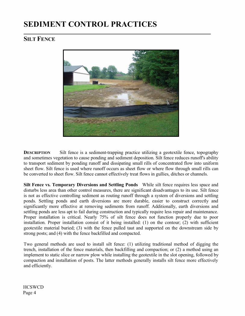
DESCRIPTION Silt fence is a sediment-trapping practice utilizing a geotextile fence, topographyand sometimes vegetation to cause ponding and sediment deposition. Silt fence reduces runoff's abilityto transport sediment by ponding runoff and dissipating small rills of concentrated flow into uniformsheet flow. Silt fence is used where runoff occurs as sheet flow or where flow through small rills canbe converted to sheet flow. Silt fence cannot effectively treat flows in gullies, ditches or channels.
Silt Fence vs. Temporary Diversions and Settling Ponds While silt fence requires less space anddisturbs less area than other control measures, there are significant disadvantages to its use. Silt fenceis not as effective controlling sediment as routing runoff through a system of diversions and settlingponds. Settling ponds and earth diversions are more durable, easier to construct correctly andsignificantly more effective at removing sediments from runoff. Additionally, earth diversions andsettling ponds are less apt to fail during construction and typically require less repair and maintenance.Proper installation is critical. Nearly 75% of silt fence does not function properly due to poorinstallation. Proper installation consist of it being installed: (1) on the contour; (2) with sufficientgeotextile material buried; (3) with the fence pulled taut and supported on the downstream side bystrong posts; and (4) with the fence backfilled and compacted.
Two general methods are used to install silt fence: (1) utilizing traditional method of digging thetrench, installation of the fence materials, then backfilling and compaction; or (2) a method using animplement to static slice or narrow plow while installing the geotextile in the slot opening, followed bycompaction and installation of posts. The latter methods generally installs silt fence more effectivelyand efficiently.
Sediment Control Practices
HCSWCDPage 5
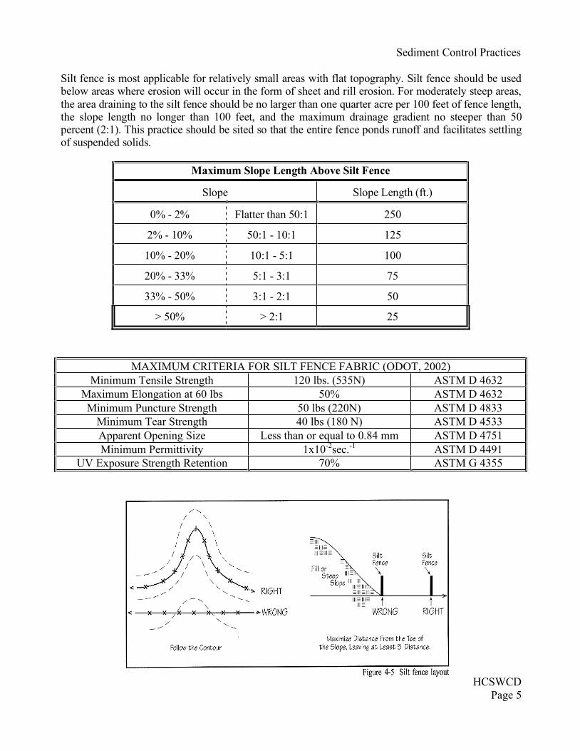
Silt fence is most applicable for relatively small areas with flat topography. Silt fence should be usedbelow areas where erosion will occur in the form of sheet and rill erosion. For moderately steep areas,the area draining to the silt fence should be no larger than one quarter acre per 100 feet of fence length,the slope length no longer than 100 feet, and the maximum drainage gradient no steeper than 50percent (2:1). This practice should be sited so that the entire fence ponds runoff and facilitates settlingof suspended solids.
MAXIMUM CRITERIA FOR SILT FENCE FABRIC (ODOT, 2002)Minimum Tensile Strength 120 lbs. (535N) ASTM D 4632
Maximum Elongation at 60 lbs 50% ASTM D 4632Minimum Puncture Strength 50 lbs (220N) ASTM D 4833
Minimum Tear Strength 40 lbs (180 N) ASTM D 4533Apparent Opening Size Less than or equal to 0.84 mm ASTM D 4751Minimum Permittivity 1x10⁻²sec.-1 ASTM D 4491
UV Exposure Strength Retention 70% ASTM G 4355
Maximum Slope Length Above Silt Fence
).tf(htgneLepolSepolS
0% - 2% Flatter than 50:1 250
2% - 10% 50:1 - 10:1 125
10% - 20% 10:1 - 5:1 100
20% - 33% 5:1 - 3:1 75
33% - 50% 3:1 - 2:1 50
> 50% > 2:1 25
HCSWCDPage 4
SEDIMENT CONTROL PRACTICES
SILT FENCE
DESCRIPTION Silt fence is a sediment-trapping practice utilizing a geotextile fence, topographyand sometimes vegetation to cause ponding and sediment deposition. Silt fence reduces runoff's abilityto transport sediment by ponding runoff and dissipating small rills of concentrated flow into uniformsheet flow. Silt fence is used where runoff occurs as sheet flow or where flow through small rills canbe converted to sheet flow. Silt fence cannot effectively treat flows in gullies, ditches or channels.
Silt Fence vs. Temporary Diversions and Settling Ponds While silt fence requires less space anddisturbs less area than other control measures, there are significant disadvantages to its use. Silt fenceis not as effective controlling sediment as routing runoff through a system of diversions and settlingponds. Settling ponds and earth diversions are more durable, easier to construct correctly andsignificantly more effective at removing sediments from runoff. Additionally, earth diversions andsettling ponds are less apt to fail during construction and typically require less repair and maintenance.Proper installation is critical. Nearly 75% of silt fence does not function properly due to poorinstallation. Proper installation consist of it being installed: (1) on the contour; (2) with sufficientgeotextile material buried; (3) with the fence pulled taut and supported on the downstream side bystrong posts; and (4) with the fence backfilled and compacted.
Two general methods are used to install silt fence: (1) utilizing traditional method of digging thetrench, installation of the fence materials, then backfilling and compaction; or (2) a method using animplement to static slice or narrow plow while installing the geotextile in the slot opening, followed bycompaction and installation of posts. The latter methods generally installs silt fence more effectivelyand efficiently.
Sediment Control Practices
HCSWCDPage 5
Silt fence is most applicable for relatively small areas with flat topography. Silt fence should be usedbelow areas where erosion will occur in the form of sheet and rill erosion. For moderately steep areas,the area draining to the silt fence should be no larger than one quarter acre per 100 feet of fence length,the slope length no longer than 100 feet, and the maximum drainage gradient no steeper than 50percent (2:1). This practice should be sited so that the entire fence ponds runoff and facilitates settlingof suspended solids.
MAXIMUM CRITERIA FOR SILT FENCE FABRIC (ODOT, 2002)Minimum Tensile Strength 120 lbs. (535N) ASTM D 4632
Maximum Elongation at 60 lbs 50% ASTM D 4632Minimum Puncture Strength 50 lbs (220N) ASTM D 4833
Minimum Tear Strength 40 lbs (180 N) ASTM D 4533Apparent Opening Size Less than or equal to 0.84 mm ASTM D 4751Minimum Permittivity 1x10⁻²sec.-1 ASTM D 4491
UV Exposure Strength Retention 70% ASTM G 4355
Maximum Slope Length Above Silt Fence
).tf(htgneLepolSepolS
0% - 2% Flatter than 50:1 250
2% - 10% 50:1 - 10:1 125
10% - 20% 10:1 - 5:1 100
20% - 33% 5:1 - 3:1 75
33% - 50% 3:1 - 2:1 50
> 50% > 2:1 25
Sediment Control Practices
HCSWCDPage 6
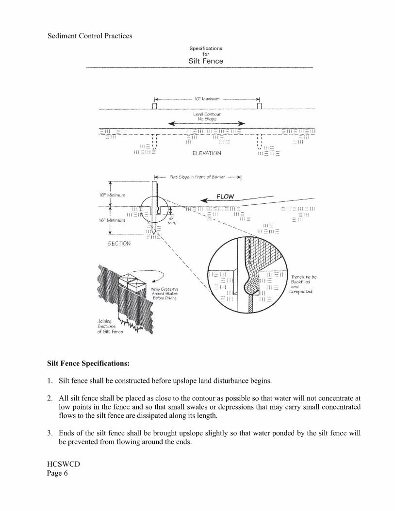
Silt Fence Specifications:
1. Silt fence shall be constructed before upslope land disturbance begins.
2. All silt fence shall be placed as close to the contour as possible so that water will not concentrate atlow points in the fence and so that small swales or depressions that may carry small concentratedflows to the silt fence are dissipated along its length.
3. Ends of the silt fence shall be brought upslope slightly so that water ponded by the silt fence willbe prevented from flowing around the ends.
Sediment Control Practices
HCSWCDPage 7
4. Silt fence shall be placed on the flattest area available.
5. Where possible, vegetation shall be preserved for 5 ft. (or as much as possible) upslope from thesilt fence. If vegetation is removed, it shall be reestablished within 7 days from the installation ofthe silt fence.
6. The height of the silt fence shall be a minimum of 16 inches above the original ground surface.
7. The silt fence shall be placed in an excavated or sliced trench cut a minimum of 6 inches deep. Thetrench shall be made with a trencher, cable laying machine, slicing machine or other suitabledevice that will ensure an adequately uniform trench depth.
8. The silt fence shall be placed with the stakes on the downslope side of the geotextile. A minimumof 8 inches of geotextile must be below the ground surface. Excess material shall lay on the bottomof the 6 inch deep trench. The trench shall be backfilled and compacted on both sides of the fabric.
9. Seams between sections of silt fence shall be spliced together only at a support post with aminimum 6 inches overlap prior to driving into the ground (see details).
10. Maintenance—Silt fence shall allow runoff to pass only as diffuse flow through the geotextile. Ifrunoff overtops the silt fence, flows under the fabric or around the fence ends, or in any other wayallows a concentrated flow discharge, one of the following shall be performed, as appropriate:1) The layout of the silt fence shall be changed, 2) Accumulated sediment shall be removed, or3) Other practices shall be installed.
Sediment deposits shall be routinely removed when deposits reaches approximately one-half of theheight of the silt fence.
Silt fence shall be inspected after each rainfall and at least daily during a prolonged rainfall. Thelocation of existing silt fence shall be reviewed daily to ensure its proper location andeffectiveness. If damaged, the silt fence shall be repaired immediately.
Criteria for Silt Fence Materials:
1) Fence Posts – The length shall be a minimum of 32 inches. Wood posts will be 2 by 2 inchesnominal dimensioned hardwood of sound quality. They shall be free of knots, splits and other visibleimperfections that will weaken the posts. The maximum spacing between posts shall be 10 feet. Postsshall be driven a minimum 16 inches into the ground, where possible. If not possible, the posts shall beadequately secured to prevent overturning of the fence due to sediment/water loading.
2) Silt fence fabric – see chart (Maximum Criteria for Silt Fence Fabric, above)
Sediment Control Practices
HCSWCDPage 6
Silt Fence Specifications:
1. Silt fence shall be constructed before upslope land disturbance begins.
2. All silt fence shall be placed as close to the contour as possible so that water will not concentrate atlow points in the fence and so that small swales or depressions that may carry small concentratedflows to the silt fence are dissipated along its length.
3. Ends of the silt fence shall be brought upslope slightly so that water ponded by the silt fence willbe prevented from flowing around the ends.
Sediment Control Practices
HCSWCDPage 7
4. Silt fence shall be placed on the flattest area available.
5. Where possible, vegetation shall be preserved for 5 ft. (or as much as possible) upslope from thesilt fence. If vegetation is removed, it shall be reestablished within 7 days from the installation ofthe silt fence.
6. The height of the silt fence shall be a minimum of 16 inches above the original ground surface.
7. The silt fence shall be placed in an excavated or sliced trench cut a minimum of 6 inches deep. Thetrench shall be made with a trencher, cable laying machine, slicing machine or other suitabledevice that will ensure an adequately uniform trench depth.
8. The silt fence shall be placed with the stakes on the downslope side of the geotextile. A minimumof 8 inches of geotextile must be below the ground surface. Excess material shall lay on the bottomof the 6 inch deep trench. The trench shall be backfilled and compacted on both sides of the fabric.
9. Seams between sections of silt fence shall be spliced together only at a support post with aminimum 6 inches overlap prior to driving into the ground (see details).
10. Maintenance—Silt fence shall allow runoff to pass only as diffuse flow through the geotextile. Ifrunoff overtops the silt fence, flows under the fabric or around the fence ends, or in any other wayallows a concentrated flow discharge, one of the following shall be performed, as appropriate:1) The layout of the silt fence shall be changed, 2) Accumulated sediment shall be removed, or3) Other practices shall be installed.
Sediment deposits shall be routinely removed when deposits reaches approximately one-half of theheight of the silt fence.
Silt fence shall be inspected after each rainfall and at least daily during a prolonged rainfall. Thelocation of existing silt fence shall be reviewed daily to ensure its proper location andeffectiveness. If damaged, the silt fence shall be repaired immediately.
Criteria for Silt Fence Materials:
1) Fence Posts – The length shall be a minimum of 32 inches. Wood posts will be 2 by 2 inchesnominal dimensioned hardwood of sound quality. They shall be free of knots, splits and other visibleimperfections that will weaken the posts. The maximum spacing between posts shall be 10 feet. Postsshall be driven a minimum 16 inches into the ground, where possible. If not possible, the posts shall beadequately secured to prevent overturning of the fence due to sediment/water loading.
2) Silt fence fabric – see chart (Maximum Criteria for Silt Fence Fabric, above)
Sediment Control Practices
HCSWCDPage 8
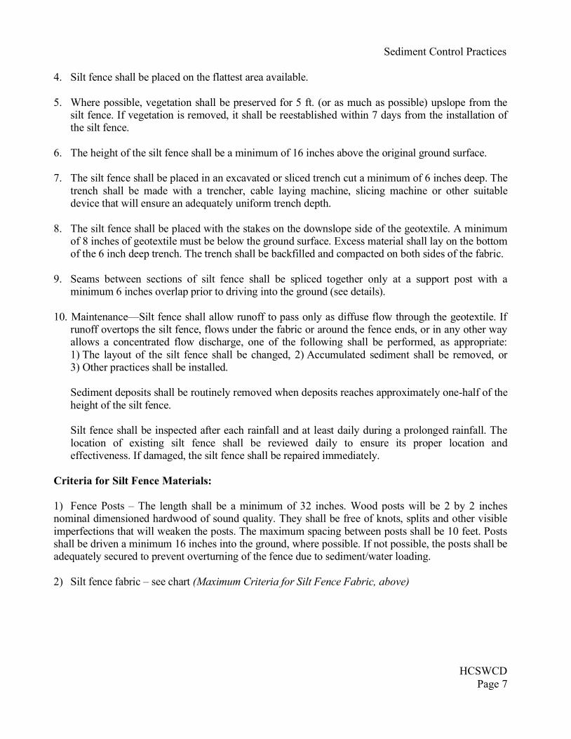
SUPER SILT FENCE
A temporary barrier of geotextile fabric over welded wire fencing reinforced with metal polesused to intercept sediment laden runoff from small drainage areas. The same practices andcriteria from silt fence apply to super silt fence.
Welded wire fencing shall be fastened securely to the metal fence posts with wire ties.Filter cloth shall be fastened securely to the fencing with ties spaced every 24” at the topand mid section.
Filter cloth shall be imbedded a minimum of 8” into the ground.When two sections of filter cloth adjoin each other, they shall be overlapped by 6” andfolded.
Maintenance shall be performed as needed and silt buildups removed when bulgesdevelop in the silt fence.
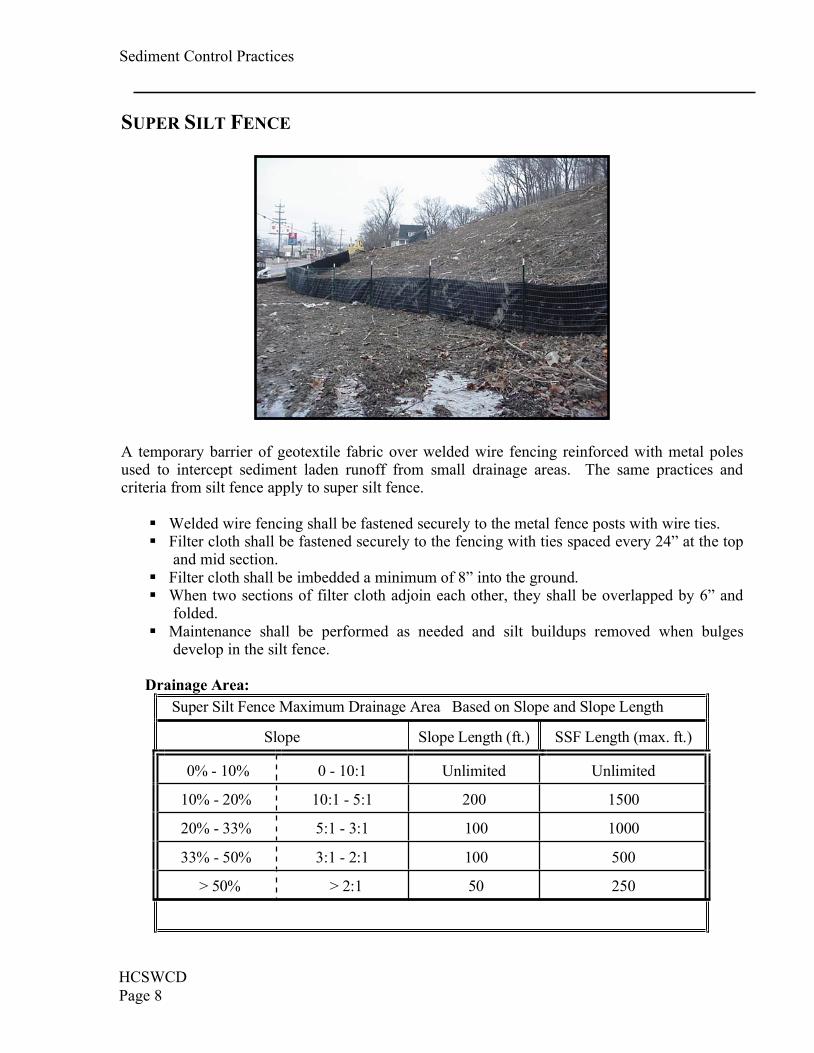
Drainage Area:Super Silt Fence Maximum Drainage Area Based on Slope and Slope Length
Slope Slope Length (ft.) SSF Length (max. ft.)
0% - 10% 0 - 10:1 Unlimited Unlimited
10% - 20% 10:1 - 5:1 200 1500
20% - 33% 5:1 - 3:1 100 1000
33% - 50% 3:1 - 2:1 100 500
> 50% > 2:1 50 250
Sediment Control Practices
HCSWCDPage 9
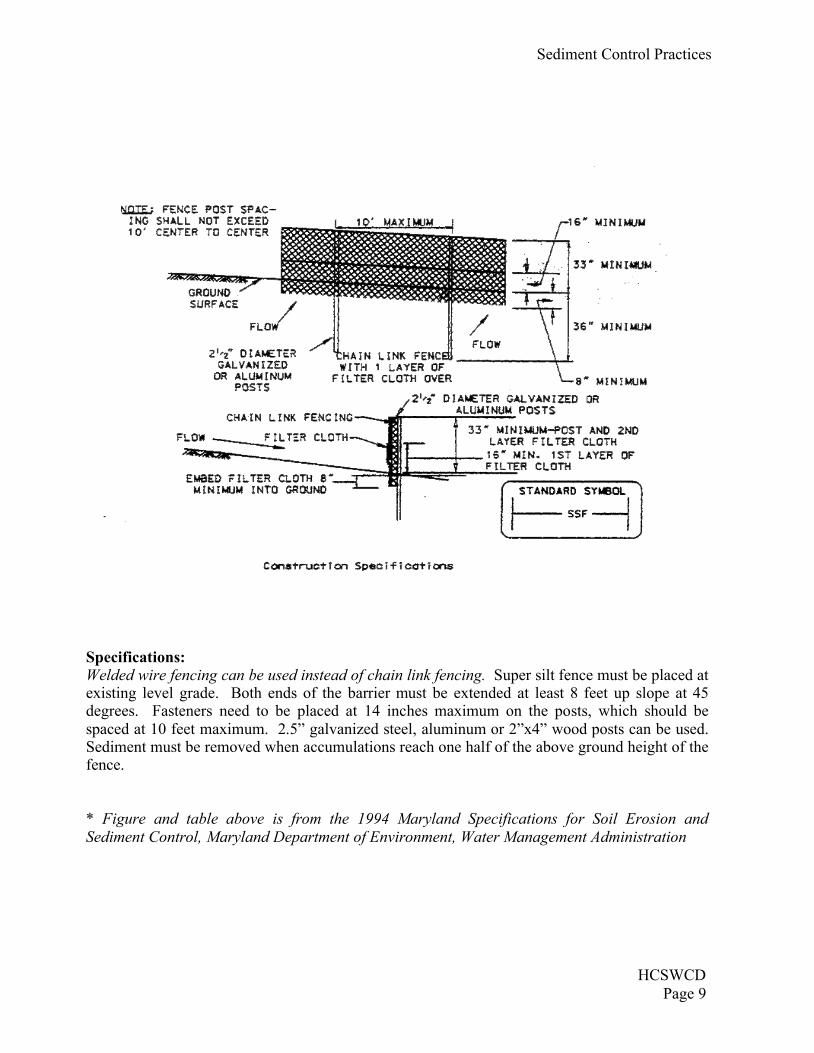
Specifications:Welded wire fencing can be used instead of chain link fencing. Super silt fence must be placed atexisting level grade. Both ends of the barrier must be extended at least 8 feet up slope at 45degrees. Fasteners need to be placed at 14 inches maximum on the posts, which should bespaced at 10 feet maximum. 2.5” galvanized steel, aluminum or 2”x4” wood posts can be used.Sediment must be removed when accumulations reach one half of the above ground height of thefence.
* Figure and table above is from the 1994 Maryland Specifications for Soil Erosion andSediment Control, Maryland Department of Environment, Water Management Administration
Sediment Control Practices
HCSWCDPage 8
SUPER SILT FENCE
A temporary barrier of geotextile fabric over welded wire fencing reinforced with metal polesused to intercept sediment laden runoff from small drainage areas. The same practices andcriteria from silt fence apply to super silt fence.
Welded wire fencing shall be fastened securely to the metal fence posts with wire ties.Filter cloth shall be fastened securely to the fencing with ties spaced every 24” at the topand mid section.
Filter cloth shall be imbedded a minimum of 8” into the ground.When two sections of filter cloth adjoin each other, they shall be overlapped by 6” andfolded.
Maintenance shall be performed as needed and silt buildups removed when bulgesdevelop in the silt fence.
Drainage Area:Super Silt Fence Maximum Drainage Area Based on Slope and Slope Length
Slope Slope Length (ft.) SSF Length (max. ft.)
0% - 10% 0 - 10:1 Unlimited Unlimited
10% - 20% 10:1 - 5:1 200 1500
20% - 33% 5:1 - 3:1 100 1000
33% - 50% 3:1 - 2:1 100 500
> 50% > 2:1 50 250
Sediment Control Practices
HCSWCDPage 9
Specifications:Welded wire fencing can be used instead of chain link fencing. Super silt fence must be placed atexisting level grade. Both ends of the barrier must be extended at least 8 feet up slope at 45degrees. Fasteners need to be placed at 14 inches maximum on the posts, which should bespaced at 10 feet maximum. 2.5” galvanized steel, aluminum or 2”x4” wood posts can be used.Sediment must be removed when accumulations reach one half of the above ground height of thefence.
* Figure and table above is from the 1994 Maryland Specifications for Soil Erosion andSediment Control, Maryland Department of Environment, Water Management Administration
Sediment Control Practices
HCSWCDPage 10
MULCH/FILTER BERMS
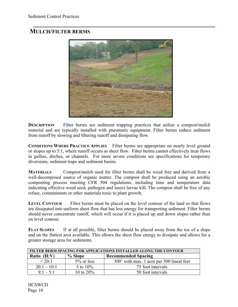
FILTER BERM SPACING FOR APPLICATIONS INSTALLED ALONG THE CONTOURRatio (H:V) % Slope Recommended Spacing
< 20:1 5% or less 300’ with max. 1 acre per 500 lineal feet20:1 – 10:1 5 to 10% 75 foot intervals9:1 – 5:1 10 to 20% 50 foot intervals
DESCRIPTION Filter berms are sediment trapping practices that utilize a compost/mulchmaterial and are typically installed with pneumatic equipment. Filter berms reduce sedimentfrom runoff by slowing and filtering runoff and dissipating flow.
CONDITIONS WHERE PRACTICE APPLIES Filter berms are appropriate on nearly level groundor slopes up to 5:1, where runoff occurs as sheet flow. Filter berms cannot effectively treat flowsin gullies, ditches, or channels. For more severe conditions see specifications for temporarydiversions, sediment traps and sediment basins.
MATERIALS Compost/mulch used for filter berms shall be weed free and derived from awell-decomposed source of organic matter. The compost shall be produced using an aerobiccomposting process meeting CFR 504 regulations, including time and temperature dataindicating effective weed seed, pathogen and insect larvae kill. The compost shall be free of anyrefuse, contaminants or other materials toxic to plant growth.
LEVEL CONTOUR Filter berms must be placed on the level contour of the land so that flowsare dissipated into uniform sheet flow that has less energy for transporting sediment. Filter bermsshould never concentrate runoff, which will occur if it is placed up and down slopes rather thanon level contour.
FLAT SLOPES If at all possible, filter berms should be placed away from the toe of a slopeand on the flattest area available. This allows the sheet flow energy to dissipate and allows for agreater storage area for sediments.
Sediment Control Practices
HCSWCD
Page 11
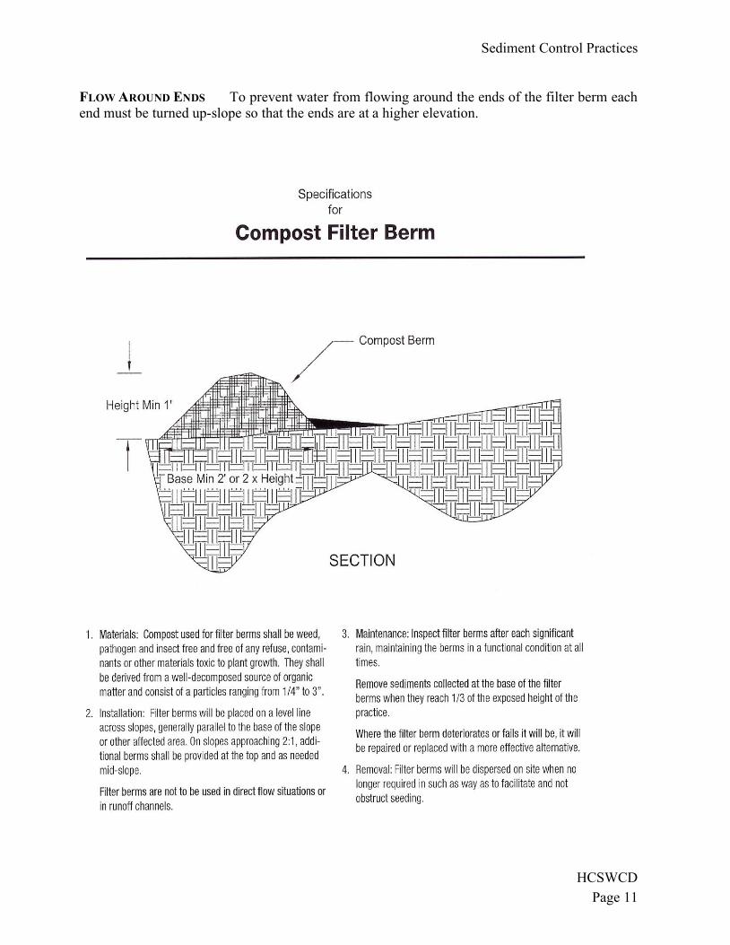
FLOW AROUND ENDS To prevent water from flowing around the ends of the filter berm each end must be turned up-slope so that the ends are at a higher elevation.
Sediment Control Practices
HCSWCDPage 10
MULCH/FILTER BERMS
FILTER BERM SPACING FOR APPLICATIONS INSTALLED ALONG THE CONTOURRatio (H:V) % Slope Recommended Spacing
< 20:1 5% or less 300’ with max. 1 acre per 500 lineal feet20:1 – 10:1 5 to 10% 75 foot intervals9:1 – 5:1 10 to 20% 50 foot intervals
DESCRIPTION Filter berms are sediment trapping practices that utilize a compost/mulchmaterial and are typically installed with pneumatic equipment. Filter berms reduce sedimentfrom runoff by slowing and filtering runoff and dissipating flow.
CONDITIONS WHERE PRACTICE APPLIES Filter berms are appropriate on nearly level groundor slopes up to 5:1, where runoff occurs as sheet flow. Filter berms cannot effectively treat flowsin gullies, ditches, or channels. For more severe conditions see specifications for temporarydiversions, sediment traps and sediment basins.
MATERIALS Compost/mulch used for filter berms shall be weed free and derived from awell-decomposed source of organic matter. The compost shall be produced using an aerobiccomposting process meeting CFR 504 regulations, including time and temperature dataindicating effective weed seed, pathogen and insect larvae kill. The compost shall be free of anyrefuse, contaminants or other materials toxic to plant growth.
LEVEL CONTOUR Filter berms must be placed on the level contour of the land so that flowsare dissipated into uniform sheet flow that has less energy for transporting sediment. Filter bermsshould never concentrate runoff, which will occur if it is placed up and down slopes rather thanon level contour.
FLAT SLOPES If at all possible, filter berms should be placed away from the toe of a slopeand on the flattest area available. This allows the sheet flow energy to dissipate and allows for agreater storage area for sediments.
Sediment Control Practices
HCSWCD
Page 11
FLOW AROUND ENDS To prevent water from flowing around the ends of the filter berm each end must be turned up-slope so that the ends are at a higher elevation.
Sediment Control Practices
HCSWCDPage 12
STORM DRAIN INLET PROTECTION
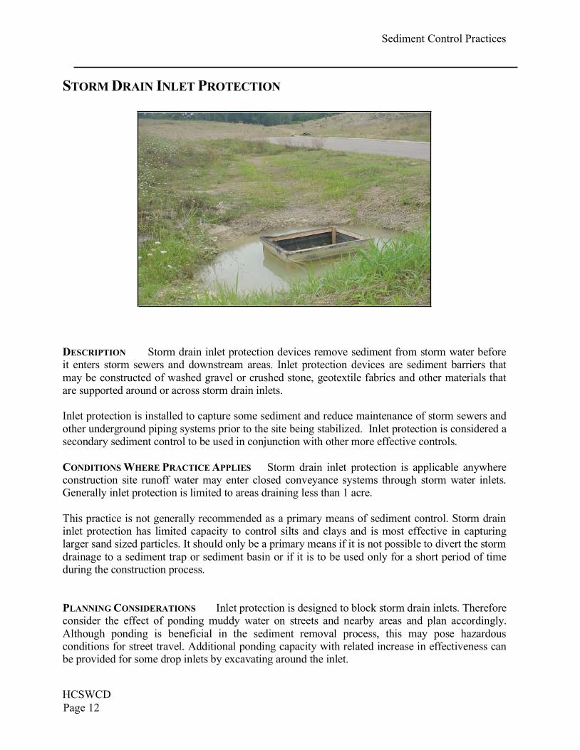
DESCRIPTION Storm drain inlet protection devices remove sediment from storm water beforeit enters storm sewers and downstream areas. Inlet protection devices are sediment barriers thatmay be constructed of washed gravel or crushed stone, geotextile fabrics and other materials thatare supported around or across storm drain inlets.
Inlet protection is installed to capture some sediment and reduce maintenance of storm sewers andother underground piping systems prior to the site being stabilized. Inlet protection is considered asecondary sediment control to be used in conjunction with other more effective controls.
CONDITIONS WHERE PRACTICE APPLIES Storm drain inlet protection is applicable anywhereconstruction site runoff water may enter closed conveyance systems through storm water inlets.Generally inlet protection is limited to areas draining less than 1 acre.
This practice is not generally recommended as a primary means of sediment control. Storm draininlet protection has limited capacity to control silts and clays and is most effective in capturinglarger sand sized particles. It should only be a primary means if it is not possible to divert the stormdrainage to a sediment trap or sediment basin or if it is to be used only for a short period of timeduring the construction process.
PLANNING CONSIDERATIONS Inlet protection is designed to block storm drain inlets. Thereforeconsider the effect of ponding muddy water on streets and nearby areas and plan accordingly.Although ponding is beneficial in the sediment removal process, this may pose hazardousconditions for street travel. Additional ponding capacity with related increase in effectiveness canbe provided for some drop inlets by excavating around the inlet.
Sediment Control Practices
HCSWCD
Page 13
Utilizing inlet protection on long sloping streets may cause runoff to bypass inlets on the slope and cause extra water to accumulate in low areas. In order for the inlet protection to work, ponding
must be maintained at the practice.
Apply storm drain inlet protection as soon as the surface inlet is capable of receiving storm water. Geotextiles utilized in inlet protection are manufactured to control the rate of storm water flow and
to retain certain sizes of soil particles. The controlled flow and ponding assists in sediment deposition. Geotextile fabrics come in a variety of materials with permeability, strength and durability ratings. In all cases, follow the manufacturer’s recommendation for the specific product
application, as well as installation and maintenance requirements.
All inlet protection practices require frequent maintenance and cleaning to maintain sufficient flow
rates and to prevent accumulation of mud on streets and other areas.
The following types of storm drain inlet protection are listed according to type of flows and situations where they will perform best. Note that straw bales are not suitable as storm drain inlet
protection since they often cease to allow flow through once saturated and often leak where bales join. Different types of storm drain inlet protection available are as follows:
A) Excavated Drop Inlet Sediment Trap. Where the storm sewer can be left below the final grade, a depression in the ground adjacent to the inlet can be an effective way of reducing sediment going to the storm sewer. Runoff is directed to the depression and a sediment barrier is maintained
between the depression and the storm sewer.
B) Geotextile Inlet Protection. This method consists of placing filter fence around the perimeter of the drop inlet and backfilling. Apply this method where inlet drains overload flow or sheet flow
from gentle slopes and sheet or overland flow.
C) Geotextile-Stone Protection. These are used both on drop inlets and in street curbs and gutters
where ponding of water will not cause damage or inconvenience. This filter is simply constructed of geotextile over the inlet with stone on top. Note: this practice does not have an opening for overflow and should not be placed where clogging or subsequent flooding would cause safety
concerns or property damage.
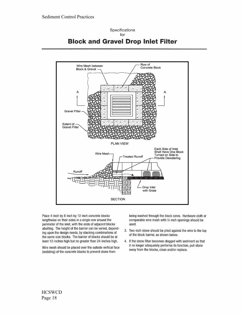
D) Block and Gravel Drop Inlet Protection. This practice utilizes a wall of cement blocks overlain with wire mesh and gravel around the perimeter to slow runoff before entering a storm drain. It is
not recommended anywhere vehicle traffic is operating.
E) Manufactured Inlet Protection Devices. Any manufactured products utilized for inlet protection
must be constructed of materials equally durable and effective as those provided in this practice. They must be able to be secured such that construction site runoff is intercepted, ponded and filtered prior to entering the storm drain except during extreme flows. Devices must allow the
removal of captured material without falling into the catch basin.
Sediment Control Practices
HCSWCDPage 12
STORM DRAIN INLET PROTECTION
DESCRIPTION Storm drain inlet protection devices remove sediment from storm water beforeit enters storm sewers and downstream areas. Inlet protection devices are sediment barriers thatmay be constructed of washed gravel or crushed stone, geotextile fabrics and other materials thatare supported around or across storm drain inlets.
Inlet protection is installed to capture some sediment and reduce maintenance of storm sewers andother underground piping systems prior to the site being stabilized. Inlet protection is considered asecondary sediment control to be used in conjunction with other more effective controls.
CONDITIONS WHERE PRACTICE APPLIES Storm drain inlet protection is applicable anywhereconstruction site runoff water may enter closed conveyance systems through storm water inlets.Generally inlet protection is limited to areas draining less than 1 acre.
This practice is not generally recommended as a primary means of sediment control. Storm draininlet protection has limited capacity to control silts and clays and is most effective in capturinglarger sand sized particles. It should only be a primary means if it is not possible to divert the stormdrainage to a sediment trap or sediment basin or if it is to be used only for a short period of timeduring the construction process.
PLANNING CONSIDERATIONS Inlet protection is designed to block storm drain inlets. Thereforeconsider the effect of ponding muddy water on streets and nearby areas and plan accordingly.Although ponding is beneficial in the sediment removal process, this may pose hazardousconditions for street travel. Additional ponding capacity with related increase in effectiveness canbe provided for some drop inlets by excavating around the inlet.
Sediment Control Practices
HCSWCD
Page 13
Utilizing inlet protection on long sloping streets may cause runoff to bypass inlets on the slope and cause extra water to accumulate in low areas. In order for the inlet protection to work, ponding
must be maintained at the practice.
Apply storm drain inlet protection as soon as the surface inlet is capable of receiving storm water. Geotextiles utilized in inlet protection are manufactured to control the rate of storm water flow and
to retain certain sizes of soil particles. The controlled flow and ponding assists in sediment deposition. Geotextile fabrics come in a variety of materials with permeability, strength and durability ratings. In all cases, follow the manufacturer’s recommendation for the specific product
application, as well as installation and maintenance requirements.
All inlet protection practices require frequent maintenance and cleaning to maintain sufficient flow
rates and to prevent accumulation of mud on streets and other areas.
The following types of storm drain inlet protection are listed according to type of flows and situations where they will perform best. Note that straw bales are not suitable as storm drain inlet
protection since they often cease to allow flow through once saturated and often leak where bales join. Different types of storm drain inlet protection available are as follows:
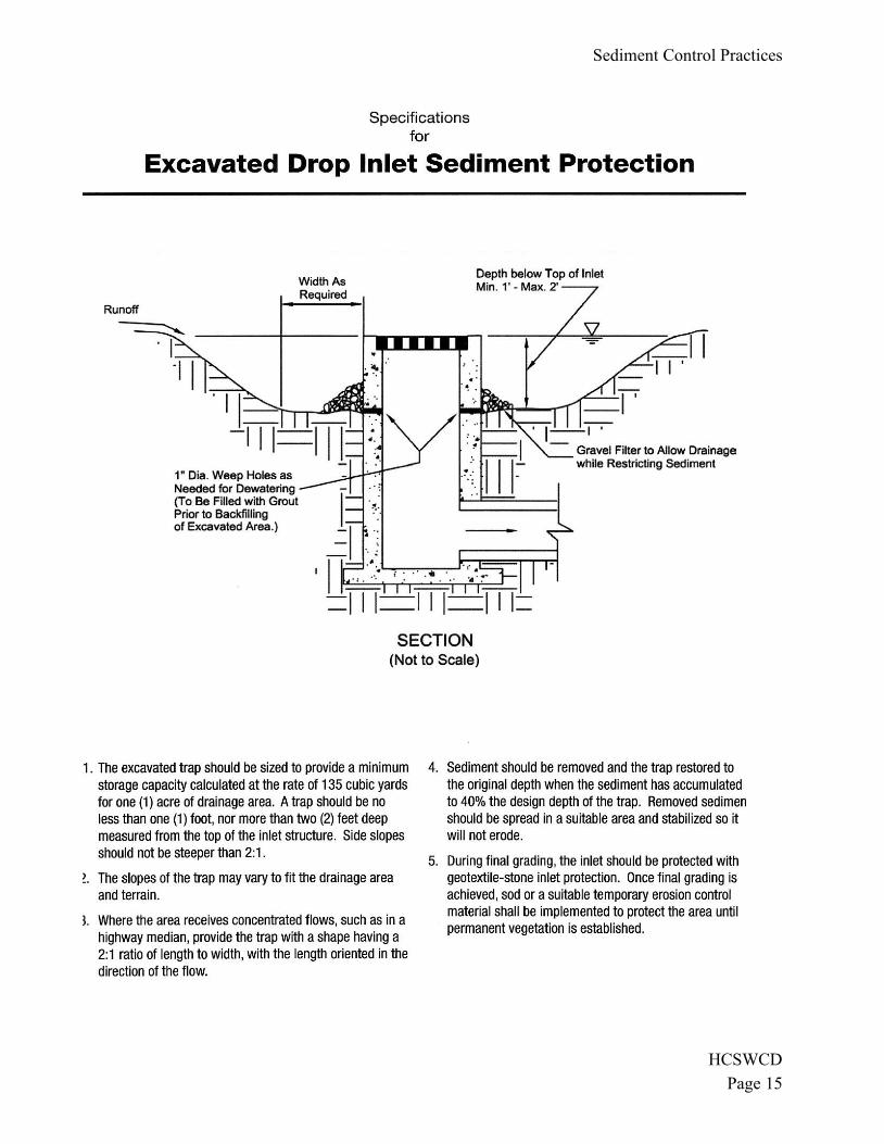
A) Excavated Drop Inlet Sediment Trap. Where the storm sewer can be left below the final grade, a depression in the ground adjacent to the inlet can be an effective way of reducing sediment going to the storm sewer. Runoff is directed to the depression and a sediment barrier is maintained
between the depression and the storm sewer.
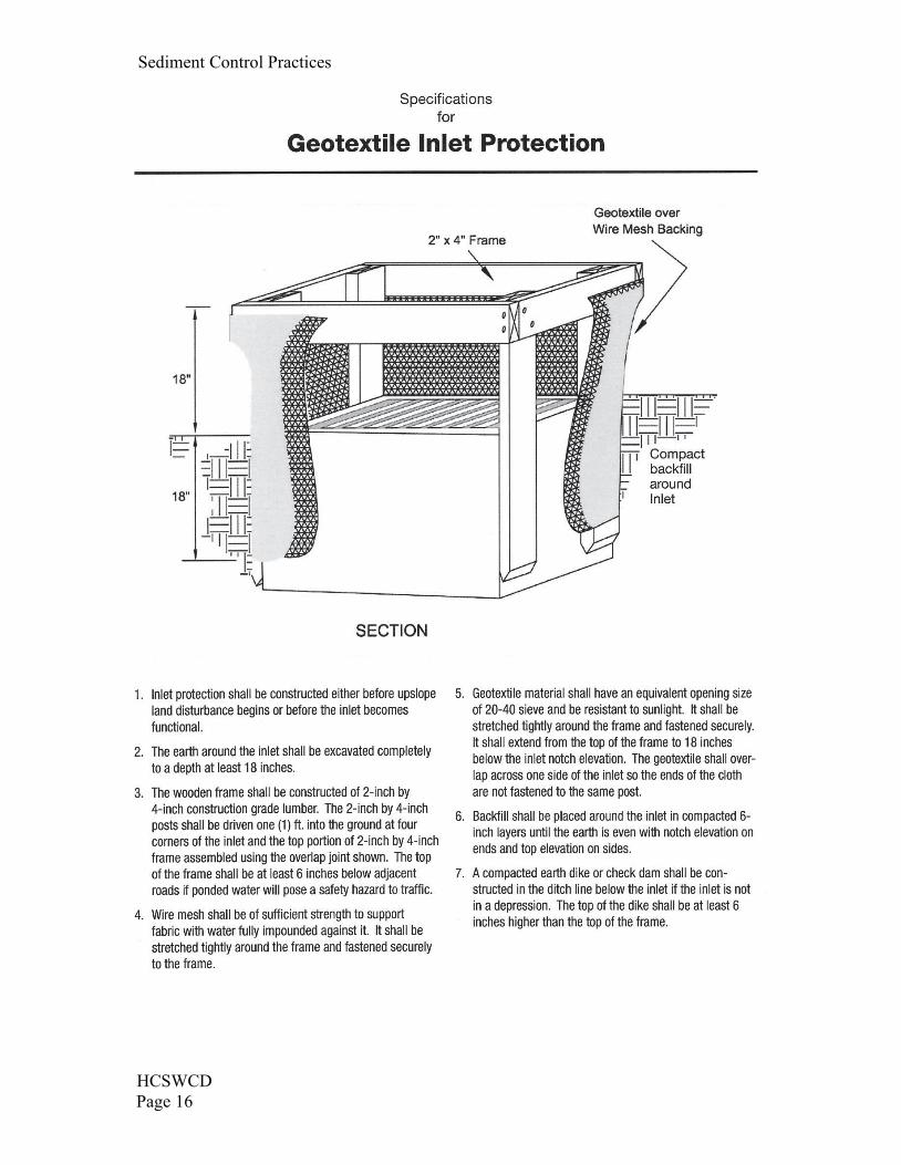
B) Geotextile Inlet Protection. This method consists of placing filter fence around the perimeter of the drop inlet and backfilling. Apply this method where inlet drains overload flow or sheet flow
from gentle slopes and sheet or overland flow.
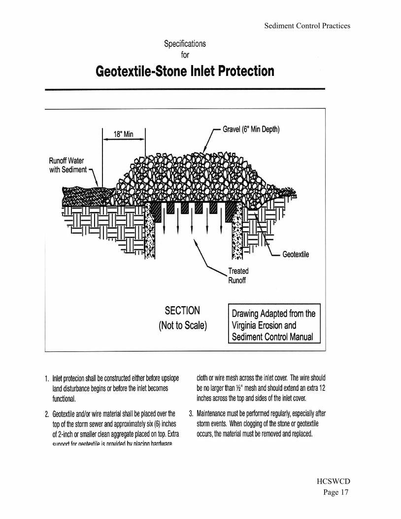
C) Geotextile-Stone Protection. These are used both on drop inlets and in street curbs and gutters
where ponding of water will not cause damage or inconvenience. This filter is simply constructed of geotextile over the inlet with stone on top. Note: this practice does not have an opening for overflow and should not be placed where clogging or subsequent flooding would cause safety
concerns or property damage.
D) Block and Gravel Drop Inlet Protection. This practice utilizes a wall of cement blocks overlain with wire mesh and gravel around the perimeter to slow runoff before entering a storm drain. It is
not recommended anywhere vehicle traffic is operating.
E) Manufactured Inlet Protection Devices. Any manufactured products utilized for inlet protection
must be constructed of materials equally durable and effective as those provided in this practice. They must be able to be secured such that construction site runoff is intercepted, ponded and filtered prior to entering the storm drain except during extreme flows. Devices must allow the
removal of captured material without falling into the catch basin.
Sediment Control Practices
HCSWCDPage 14
MAINTENANCE
Effective storm drain inlet protection collects sediment and therefore must be cleaned regularly toprevent clogging and subsequent flooding conditions, piping or overtopping of the controlstructures. Sediment barriers that sag, fall over or are not properly secured, must be promptlyrepaired or replaced.
Inlet protection shall be inspected weekly and after each rainfall event. Areas where there is activetraffic shall be inspected daily. Repairs shall be made as needed to assure the practice is performingas intended. Sediment shall be removed when accumulation is one-half the height of the trap.Sediment shall not be washed into the inlet. Sediment shall be removed and placed in a locationwhere it is stable and not subject to erosion.
Once the contributing drainage area has been properly stabilized, all filter material and collectedsediment shall be removed and properly disposed.
Sediment Control Practices
HCSWCD
Page 15
Sediment Control Practices
HCSWCDPage 16
Sediment Control Practices
HCSWCD
Page 17
Sediment Control Practices
HCSWCDPage 16
Sediment Control Practices
HCSWCD
Page 17
Sediment Control Practices
HCSWCDPage 18
HCSWCD
Page 19
EROSION PREVENTION PRACTICES
PERMANENT SEEDING
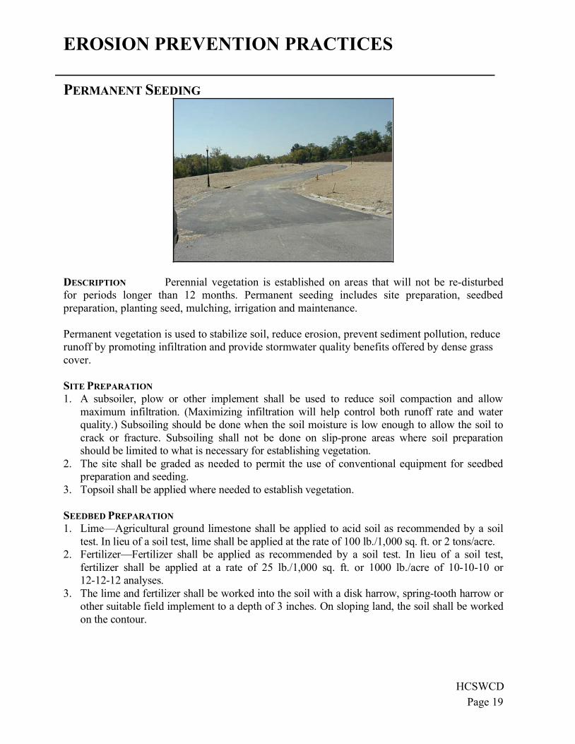
DESCRIPTION Perennial vegetation is established on areas that will not be re-disturbed
for periods longer than 12 months. Permanent seeding includes site preparation, seedbed
preparation, planting seed, mulching, irrigation and maintenance.
Permanent vegetation is used to stabilize soil, reduce erosion, prevent sediment pollution, reduce
runoff by promoting infiltration and provide stormwater quality benefits offered by dense grass
cover.
SITE PREPARATION
1. A subsoiler, plow or other implement shall be used to reduce soil compaction and allow
maximum infiltration. (Maximizing infiltration will help control both runoff rate and water
quality.) Subsoiling should be done when the soil moisture is low enough to allow the soil to
crack or fracture. Subsoiling shall not be done on slip-prone areas where soil preparation
should be limited to what is necessary for establishing vegetation.
2. The site shall be graded as needed to permit the use of conventional equipment for seedbed
preparation and seeding.
3. Topsoil shall be applied where needed to establish vegetation.
SEEDBED PREPARATION
1. Lime—Agricultural ground limestone shall be applied to acid soil as recommended by a soil
test. In lieu of a soil test, lime shall be applied at the rate of 100 lb./1,000 sq. ft. or 2 tons/acre.
2. Fertilizer—Fertilizer shall be applied as recommended by a soil test. In lieu of a soil test,
fertilizer shall be applied at a rate of 25 lb./1,000 sq. ft. or 1000 lb./acre of 10-10-10 or
12-12-12 analyses.
3. The lime and fertilizer shall be worked into the soil with a disk harrow, spring-tooth harrow or
other suitable field implement to a depth of 3 inches. On sloping land, the soil shall be worked
on the contour.
Sediment Control Practices
HCSWCDPage 18
HCSWCD
Page 19
EROSION PREVENTION PRACTICES
PERMANENT SEEDING
DESCRIPTION Perennial vegetation is established on areas that will not be re-disturbed
for periods longer than 12 months. Permanent seeding includes site preparation, seedbed
preparation, planting seed, mulching, irrigation and maintenance.
Permanent vegetation is used to stabilize soil, reduce erosion, prevent sediment pollution, reduce
runoff by promoting infiltration and provide stormwater quality benefits offered by dense grass
cover.
SITE PREPARATION
1. A subsoiler, plow or other implement shall be used to reduce soil compaction and allow
maximum infiltration. (Maximizing infiltration will help control both runoff rate and water
quality.) Subsoiling should be done when the soil moisture is low enough to allow the soil to
crack or fracture. Subsoiling shall not be done on slip-prone areas where soil preparation
should be limited to what is necessary for establishing vegetation.
2. The site shall be graded as needed to permit the use of conventional equipment for seedbed
preparation and seeding.
3. Topsoil shall be applied where needed to establish vegetation.
SEEDBED PREPARATION
1. Lime—Agricultural ground limestone shall be applied to acid soil as recommended by a soil
test. In lieu of a soil test, lime shall be applied at the rate of 100 lb./1,000 sq. ft. or 2 tons/acre.
2. Fertilizer—Fertilizer shall be applied as recommended by a soil test. In lieu of a soil test,
fertilizer shall be applied at a rate of 25 lb./1,000 sq. ft. or 1000 lb./acre of 10-10-10 or
12-12-12 analyses.
3. The lime and fertilizer shall be worked into the soil with a disk harrow, spring-tooth harrow or
other suitable field implement to a depth of 3 inches. On sloping land, the soil shall be worked
on the contour.
Erosion Prevention Practices
HCSWCD
Page 20
SEEDING DATES AND SOIL CONDITIONS Seeding should be done March 1 to May 31 or Aug 1
to September 30. If seeding occurs outside of the above specified dates, additional mulch and
irrigation may be required to ensure a minimum of 80% germination. Tillage for seedbed
preparation should be done when soil is dry enough to crumble and not form ribbons when
compressed by hand. For winter seeding, see the following section on dormant seeding.
DORMANT SEEDING
1. Seedings should not be made from October 1 through November 20. During this period, the
seeds are likely to germinate but probably will not be able to survive the winter.
2. The following methods may be used for "Dormant Seeding":
From October 1 through November 20, prepare the seedbed, add the required amounts of
lime and fertilizer, then mulch and anchor. After November 20, broadcast the selected seed
mixture at a 50% increase in the seeding rate.
From November 20 through March 15, when soil conditions permit, prepare the seedbed,
lime and fertilize, apply the selected seed mixture, mulch and anchor. Increase the seeding
rates by 50% for this type of seeding.
Apply seed uniformly with a cyclone seeder, drill, cultipacker seeder or hydro-seeder
(slurry may include seed and fertilizer) on a firm, moist seedbed.
Where feasible, except when a cultipacker type seeder is used, the seedbed should be
firmed following seeding operations with a cultipacker, roller or light drag. On sloping
land, seeding operations should follow the contour where feasible.
MULCHING
1. Mulch material shall be applied immediately after seeding. Dormant seeding shall be mulched.
100% of the ground surface shall be covered with an approved material.
2. Materials
Straw—If straw is used it shall be unrotted small-grain straw applied at the rate of 2
tons/acre or 90 lb./1,000 sq. ft. (two to three bales). The mulch shall be spread uniformly by
hand or mechanically so the soil surface is covered. For uniform distribution of hand-
spread mulch, divide area into approximately 1,000-sq.-ft. sections and spread two 45-lb.
bales of straw in each section.
Hydroseeders—If wood cellulose fiber is used, it shall be used at 2,000 lb./acre. or 46
lb./1,000 sq. ft.
Other—Other acceptable mulches include rolled erosion control mattings or blankets
applied according to manufacturer's recommendations or wood chips applied at 6 tons/acre.
3. Straw and Mulch Anchoring Methods
Straw Mulch shall be anchored immediately to minimize loss by wind or water.
Mechanical—A disk, crimper or similar type tool shall be set straight to punch or anchor
the mulch material into the soil. Straw mechanically anchored shall not be finely chopped
but generally left longer than 6 in.
Mulch Nettings—Nettings shall be used according to the manufacturer's recommendations.
Netting may be necessary to hold mulch in place in areas of concentrated runoff and on
critical slopes.
Synthetic Binders—Synthetic binders such as Acrylic DLR (Agri-Tac), DCA-70, Petroset,
Terra Tack or equivalent may be used at rates specified by the manufacturer.
Erosion Prevention Practices
HCSWCD
Page 21
Wood Cellulose Fiber—Wood cellulose fiber binder shall be applied at a net dry weight of
750 lbs./acre. The wood cellulose fiber shall be mixed with water with the mixture
containing a maximum of 50 lbs. cellulose/100 gallons of water.
IRRIGATION
1. Permanent seeding shall include irrigation to establish vegetation during dry weather or on
adverse site conditions, which require adequate moisture for seed germination and plant
growth.
2. Irrigation rates shall be monitored to prevent erosion and damage to seeded areas from
excessive runoff.
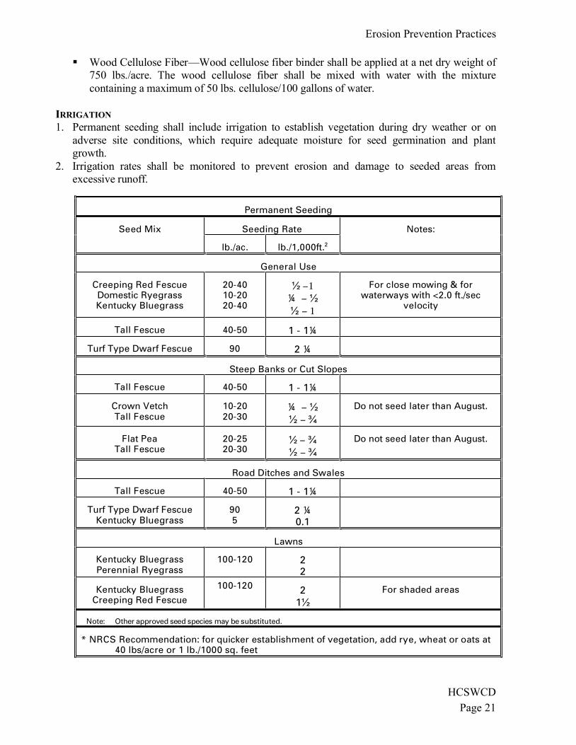
Permanent Seeding
Seed Mix Seeding Rate Notes:
lb./ac. lb./1,000ft.2
General Use
Creeping Red Fescue Domestic Ryegrass Kentucky Bluegrass
20-40 10-20 20-40
1 ¼
1
For close mowing & for waterways with <2.0 ft./sec
velocity
Tall Fescue 40-50 1 - 1¼
Turf Type Dwarf Fescue 90 2 ¼
Steep Banks or Cut Slopes
Tall Fescue 40-50 1 - 1¼
Crown Vetch Tall Fescue
10-20 20-30
¼ Do not seed later than August.
Flat Pea Tall Fescue
20-25 20-30
Do not seed later than August.
Road Ditches and Swales
Tall Fescue 40-50 1 - 1¼
Turf Type Dwarf Fescue Kentucky Bluegrass
90 5
2 ¼ 0.1
Lawns
Kentucky Bluegrass Perennial Ryegrass
100-120
2 2
Kentucky Bluegrass Creeping Red Fescue
100-120 2 1
For shaded areas
Note: Other approved seed species may be substituted.
* NRCS Recommendation: for quicker establishment of vegetation, add rye, wheat or oats at 40 lbs/acre or 1 lb./1000 sq. feet
Erosion Prevention Practices
HCSWCD
Page 20
SEEDING DATES AND SOIL CONDITIONS Seeding should be done March 1 to May 31 or Aug 1
to September 30. If seeding occurs outside of the above specified dates, additional mulch and
irrigation may be required to ensure a minimum of 80% germination. Tillage for seedbed
preparation should be done when soil is dry enough to crumble and not form ribbons when
compressed by hand. For winter seeding, see the following section on dormant seeding.
DORMANT SEEDING
1. Seedings should not be made from October 1 through November 20. During this period, the
seeds are likely to germinate but probably will not be able to survive the winter.
2. The following methods may be used for "Dormant Seeding":
From October 1 through November 20, prepare the seedbed, add the required amounts of
lime and fertilizer, then mulch and anchor. After November 20, broadcast the selected seed
mixture at a 50% increase in the seeding rate.
From November 20 through March 15, when soil conditions permit, prepare the seedbed,
lime and fertilize, apply the selected seed mixture, mulch and anchor. Increase the seeding
rates by 50% for this type of seeding.
Apply seed uniformly with a cyclone seeder, drill, cultipacker seeder or hydro-seeder
(slurry may include seed and fertilizer) on a firm, moist seedbed.
Where feasible, except when a cultipacker type seeder is used, the seedbed should be
firmed following seeding operations with a cultipacker, roller or light drag. On sloping
land, seeding operations should follow the contour where feasible.
MULCHING
1. Mulch material shall be applied immediately after seeding. Dormant seeding shall be mulched.
100% of the ground surface shall be covered with an approved material.
2. Materials
Straw—If straw is used it shall be unrotted small-grain straw applied at the rate of 2
tons/acre or 90 lb./1,000 sq. ft. (two to three bales). The mulch shall be spread uniformly by
hand or mechanically so the soil surface is covered. For uniform distribution of hand-
spread mulch, divide area into approximately 1,000-sq.-ft. sections and spread two 45-lb.
bales of straw in each section.
Hydroseeders—If wood cellulose fiber is used, it shall be used at 2,000 lb./acre. or 46
lb./1,000 sq. ft.
Other—Other acceptable mulches include rolled erosion control mattings or blankets
applied according to manufacturer's recommendations or wood chips applied at 6 tons/acre.
3. Straw and Mulch Anchoring Methods
Straw Mulch shall be anchored immediately to minimize loss by wind or water.
Mechanical—A disk, crimper or similar type tool shall be set straight to punch or anchor
the mulch material into the soil. Straw mechanically anchored shall not be finely chopped
but generally left longer than 6 in.
Mulch Nettings—Nettings shall be used according to the manufacturer's recommendations.
Netting may be necessary to hold mulch in place in areas of concentrated runoff and on
critical slopes.
Synthetic Binders—Synthetic binders such as Acrylic DLR (Agri-Tac), DCA-70, Petroset,
Terra Tack or equivalent may be used at rates specified by the manufacturer.
Erosion Prevention Practices
HCSWCD
Page 21
Wood Cellulose Fiber—Wood cellulose fiber binder shall be applied at a net dry weight of
750 lbs./acre. The wood cellulose fiber shall be mixed with water with the mixture
containing a maximum of 50 lbs. cellulose/100 gallons of water.
IRRIGATION
1. Permanent seeding shall include irrigation to establish vegetation during dry weather or on
adverse site conditions, which require adequate moisture for seed germination and plant
growth.
2. Irrigation rates shall be monitored to prevent erosion and damage to seeded areas from
excessive runoff.
Permanent Seeding
Seed Mix Seeding Rate Notes:
lb./ac. lb./1,000ft.2
General Use
Creeping Red Fescue Domestic Ryegrass Kentucky Bluegrass
20-40 10-20 20-40
1 ¼
1
For close mowing & for waterways with <2.0 ft./sec
velocity
Tall Fescue 40-50 1 - 1¼
Turf Type Dwarf Fescue 90 2 ¼
Steep Banks or Cut Slopes
Tall Fescue 40-50 1 - 1¼
Crown Vetch Tall Fescue
10-20 20-30
¼ Do not seed later than August.
Flat Pea Tall Fescue
20-25 20-30
Do not seed later than August.
Road Ditches and Swales
Tall Fescue 40-50 1 - 1¼
Turf Type Dwarf Fescue Kentucky Bluegrass
90 5
2 ¼ 0.1
Lawns
Kentucky Bluegrass Perennial Ryegrass
100-120
2 2
Kentucky Bluegrass Creeping Red Fescue
100-120 2 1
For shaded areas
Note: Other approved seed species may be substituted.
* NRCS Recommendation: for quicker establishment of vegetation, add rye, wheat or oats at 40 lbs/acre or 1 lb./1000 sq. feet
Erosion Prevention Practices
HCSWCD
Page 22
TEMPORARY ROLLED EROSION CONTROL PRODUCTS
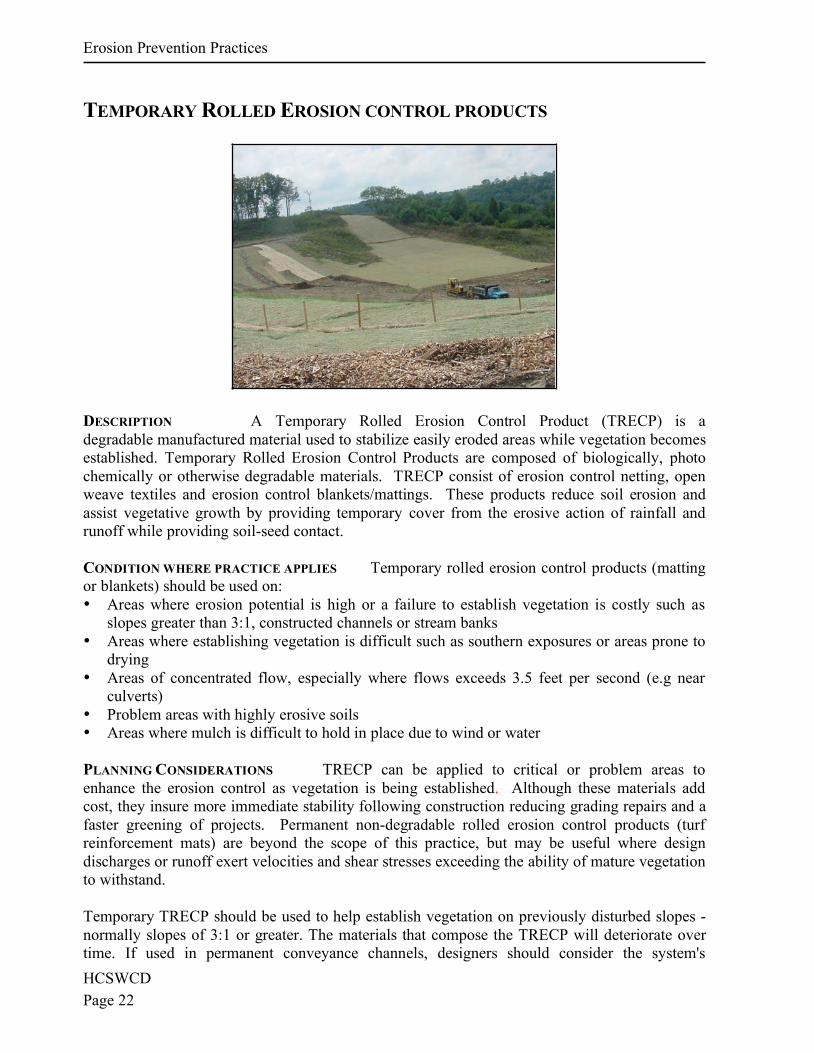
DESCRIPTION A Temporary Rolled Erosion Control Product (TRECP) is a
degradable manufactured material used to stabilize easily eroded areas while vegetation becomes
established. Temporary Rolled Erosion Control Products are composed of biologically, photo
chemically or otherwise degradable materials. TRECP consist of erosion control netting, open
weave textiles and erosion control blankets/mattings. These products reduce soil erosion and
assist vegetative growth by providing temporary cover from the erosive action of rainfall and
runoff while providing soil-seed contact.
CONDITION WHERE PRACTICE APPLIES Temporary rolled erosion control products (matting
or blankets) should be used on:
• Areas where erosion potential is high or a failure to establish vegetation is costly such as
slopes greater than 3:1, constructed channels or stream banks
• Areas where establishing vegetation is difficult such as southern exposures or areas prone to
drying
• Areas of concentrated flow, especially where flows exceeds 3.5 feet per second (e.g near
culverts)
• Problem areas with highly erosive soils
• Areas where mulch is difficult to hold in place due to wind or water
PLANNING CONSIDERATIONS TRECP can be applied to critical or problem areas to
enhance the erosion control as vegetation is being established. Although these materials add
cost, they insure more immediate stability following construction reducing grading repairs and a
faster greening of projects. Permanent non-degradable rolled erosion control products (turf
reinforcement mats) are beyond the scope of this practice, but may be useful where design
discharges or runoff exert velocities and shear stresses exceeding the ability of mature vegetation
to withstand.
Temporary TRECP should be used to help establish vegetation on previously disturbed slopes -
normally slopes of 3:1 or greater. The materials that compose the TRECP will deteriorate over
time. If used in permanent conveyance channels, designers should consider the system's
Erosion Prevention Practices
HCSWCDPage 23
resistance to erosion as it relates to the type of vegetation planted and the existing soilcharacteristics. As much as possible during establishment of vegetation, soil stabilizationblankets should not be subjected to concentrated flows moving at greater than 3.5 feet/second.
MAINTENANCE All TRECP should be inspected regularly after installation, especially afterstorms to check for erosion or undermining of the product. Make needed repairs immediately,addressing rills or gullies that have developed prior to replacing the TRECP. In the case erosionrepairs, assure that subsequent runoff across the area is dispersed or adequately spread.
COMMON PROBLEMS / CONCERNS
• Manufacturer’s selection and installation recommendations not followed. Results in failure ofthe TRECP.
• Poor contact between soil and the TRECP. Results in erosion below the TRECP and lowerseed germination rates, causing failure.
• Proper stapling guidelines not followed. Results in movement or displacement of TRECP.• Erosion check slots are not used. Results in erosion under the TRECP, causing failure. • Unstable slopes that result in TRECP or slope failure. Determine cause of slope failure,
correct, and reinstall TRECP• In channels, the width of TRECP used is not sufficient, this causes water to flow along the
sides of TRECP causing erosion. Install TRECP up side slopes of ditch line as well as thebottom.
Erosion Prevention Practices
HCSWCD
Page 22
TEMPORARY ROLLED EROSION CONTROL PRODUCTS
DESCRIPTION A Temporary Rolled Erosion Control Product (TRECP) is a
degradable manufactured material used to stabilize easily eroded areas while vegetation becomes
established. Temporary Rolled Erosion Control Products are composed of biologically, photo
chemically or otherwise degradable materials. TRECP consist of erosion control netting, open
weave textiles and erosion control blankets/mattings. These products reduce soil erosion and
assist vegetative growth by providing temporary cover from the erosive action of rainfall and
runoff while providing soil-seed contact.
CONDITION WHERE PRACTICE APPLIES Temporary rolled erosion control products (matting
or blankets) should be used on:
• Areas where erosion potential is high or a failure to establish vegetation is costly such as
slopes greater than 3:1, constructed channels or stream banks
• Areas where establishing vegetation is difficult such as southern exposures or areas prone to
drying
• Areas of concentrated flow, especially where flows exceeds 3.5 feet per second (e.g near
culverts)
• Problem areas with highly erosive soils
• Areas where mulch is difficult to hold in place due to wind or water
PLANNING CONSIDERATIONS TRECP can be applied to critical or problem areas to
enhance the erosion control as vegetation is being established. Although these materials add
cost, they insure more immediate stability following construction reducing grading repairs and a
faster greening of projects. Permanent non-degradable rolled erosion control products (turf
reinforcement mats) are beyond the scope of this practice, but may be useful where design
discharges or runoff exert velocities and shear stresses exceeding the ability of mature vegetation
to withstand.
Temporary TRECP should be used to help establish vegetation on previously disturbed slopes -
normally slopes of 3:1 or greater. The materials that compose the TRECP will deteriorate over
time. If used in permanent conveyance channels, designers should consider the system's
Erosion Prevention Practices
HCSWCDPage 23
resistance to erosion as it relates to the type of vegetation planted and the existing soilcharacteristics. As much as possible during establishment of vegetation, soil stabilizationblankets should not be subjected to concentrated flows moving at greater than 3.5 feet/second.
MAINTENANCE All TRECP should be inspected regularly after installation, especially afterstorms to check for erosion or undermining of the product. Make needed repairs immediately,addressing rills or gullies that have developed prior to replacing the TRECP. In the case erosionrepairs, assure that subsequent runoff across the area is dispersed or adequately spread.
COMMON PROBLEMS / CONCERNS
• Manufacturer’s selection and installation recommendations not followed. Results in failure ofthe TRECP.
• Poor contact between soil and the TRECP. Results in erosion below the TRECP and lowerseed germination rates, causing failure.
• Proper stapling guidelines not followed. Results in movement or displacement of TRECP.• Erosion check slots are not used. Results in erosion under the TRECP, causing failure. • Unstable slopes that result in TRECP or slope failure. Determine cause of slope failure,
correct, and reinstall TRECP• In channels, the width of TRECP used is not sufficient, this causes water to flow along the
sides of TRECP causing erosion. Install TRECP up side slopes of ditch line as well as thebottom.
Erosion Prevention Practices
HCSWCD
Page 24
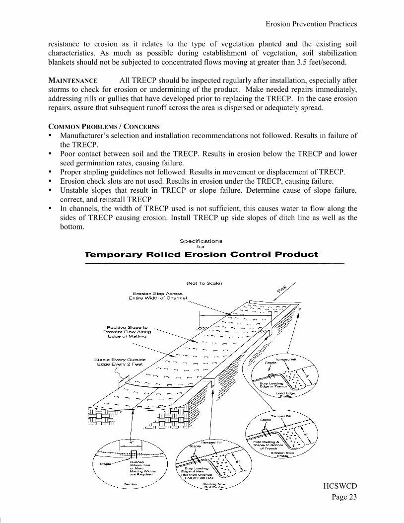
SPECIFICATIONS FOR TEMPORARY ROLLED EROSION CONTROL PRODUCT
Channel/Slope Site Preparation
1. Grade and compact area of installation.
2. Prepare seedbed by loosening 2”-3” of topsoil above final grade.
3. Incorporate amendments such as lime and fertilizer into soil.
4. Remove all rocks, clods, vegetation or other debris so that installed TRECP will have
direct contact with the soil surface.
Channel/Slope Seeding
1. Apply seed to soil surface prior to installation.
2. All check slots, anchor trenches and other disturbed areas must be reseeded.
3. Refer to the PERMANENT SEEDING specification for seeding recommendations.
Slope Installation
1. Excavate top and bottom trenches (12”x6”). Intermittent erosion check slots (6”x6”) may
be required based on slope length. Excavate top anchor trench 2’x3’ over crest of the
slope.
2. If intermittent erosion check slots are required, install TRECP in 6”x6” slot at a
maximum of 30’ centers or the mid point of the slope. TRECP should be stapled into
trench on 12” centers.
3. Install TRECP in top anchor trench, anchor on 12” spacing, backfill and compact soil.
4. Unroll TRECP down slope with adjacent rolls overlapped a minimum of 3”. Anchor the
seam every 18”.
5. Lay the TRECP loose to maintain direct soil contact, do not pull taught.
6. Overlap roll ends a minimum of 12” with upslope TRECP on top for a shingle effect.
Begin all new rolls in an erosion check slot if required; double anchor across roll every
12”.
7. Install TRECP in bottom anchor trench (12”x6”), anchor every 12”.
8. Place all other staples throughout slope at 1 to 2.5 per square yard dependant on slope.
Refer to manufactures anchor guide.
Channel Installation1. Excavate initial anchor trench (12”x6”) across the lower end of the project area.
2. Excavate intermittent check slots (6”x6”) across the channel at 30’ intervals along the
channel.
3. Excavate longitudinal channel anchor slots (4”x4”) along both sides of the channel to
bury the edges. Whenever possible extend the TRECP 2’-3’ above the crest of channel
side slopes.
4. Install TRECP in initial anchor trench (downstream) anchor every 12”, backfill and
compact soil.
5. Roll out TRECP beginning in the center of the channel toward the intermittent check slot.
Do not pull taught.
6. Unroll adjacent rolls upstream with a 3” minimum overlap (anchor every 18”) and up
each channel side slope.
7. At top of channel side slopes install TRECP in the longitudinal anchor slots, anchor every
18”.
8. Install TRECP in intermittent check slots. Lay into trench and secure with anchors every
12”, backfill with soil and compact.
Erosion Prevention Practices
HCSWCD
Page 25
9. Overlap roll ends a minimum of 12” with upstream TRECP on top for a shingling effect.
Begin all new rolls in an intermittent check slot, double anchor every 12”.
10. Install upstream end in a terminal anchor trench (12”x6”); anchor every 12”, backfill and
compact.
11. Complete anchoring throughout channel at 2.5 per square yard.
GROUND ANCHORING DEVICES
Several devices are available for anchoring including: U shaped wire staples, metal geotextile
pins, plastic stakes, and triangular wooden stakes. Anchors should be of sufficient length to
resist pullout. Longer anchors may be required in loose sandy or gravelly soils.
Erosion Prevention Practices
HCSWCD
Page 24
SPECIFICATIONS FOR TEMPORARY ROLLED EROSION CONTROL PRODUCT
Channel/Slope Site Preparation
1. Grade and compact area of installation.
2. Prepare seedbed by loosening 2”-3” of topsoil above final grade.
3. Incorporate amendments such as lime and fertilizer into soil.
4. Remove all rocks, clods, vegetation or other debris so that installed TRECP will have
direct contact with the soil surface.
Channel/Slope Seeding
1. Apply seed to soil surface prior to installation.
2. All check slots, anchor trenches and other disturbed areas must be reseeded.
3. Refer to the PERMANENT SEEDING specification for seeding recommendations.
Slope Installation
1. Excavate top and bottom trenches (12”x6”). Intermittent erosion check slots (6”x6”) may
be required based on slope length. Excavate top anchor trench 2’x3’ over crest of the
slope.
2. If intermittent erosion check slots are required, install TRECP in 6”x6” slot at a
maximum of 30’ centers or the mid point of the slope. TRECP should be stapled into
trench on 12” centers.
3. Install TRECP in top anchor trench, anchor on 12” spacing, backfill and compact soil.
4. Unroll TRECP down slope with adjacent rolls overlapped a minimum of 3”. Anchor the
seam every 18”.
5. Lay the TRECP loose to maintain direct soil contact, do not pull taught.
6. Overlap roll ends a minimum of 12” with upslope TRECP on top for a shingle effect.
Begin all new rolls in an erosion check slot if required; double anchor across roll every
12”.
7. Install TRECP in bottom anchor trench (12”x6”), anchor every 12”.
8. Place all other staples throughout slope at 1 to 2.5 per square yard dependant on slope.
Refer to manufactures anchor guide.
Channel Installation1. Excavate initial anchor trench (12”x6”) across the lower end of the project area.
2. Excavate intermittent check slots (6”x6”) across the channel at 30’ intervals along the
channel.
3. Excavate longitudinal channel anchor slots (4”x4”) along both sides of the channel to
bury the edges. Whenever possible extend the TRECP 2’-3’ above the crest of channel
side slopes.
4. Install TRECP in initial anchor trench (downstream) anchor every 12”, backfill and
compact soil.
5. Roll out TRECP beginning in the center of the channel toward the intermittent check slot.
Do not pull taught.
6. Unroll adjacent rolls upstream with a 3” minimum overlap (anchor every 18”) and up
each channel side slope.
7. At top of channel side slopes install TRECP in the longitudinal anchor slots, anchor every
18”.
8. Install TRECP in intermittent check slots. Lay into trench and secure with anchors every
12”, backfill with soil and compact.
Erosion Prevention Practices
HCSWCD
Page 25
9. Overlap roll ends a minimum of 12” with upstream TRECP on top for a shingling effect.
Begin all new rolls in an intermittent check slot, double anchor every 12”.
10. Install upstream end in a terminal anchor trench (12”x6”); anchor every 12”, backfill and
compact.
11. Complete anchoring throughout channel at 2.5 per square yard.
GROUND ANCHORING DEVICES
Several devices are available for anchoring including: U shaped wire staples, metal geotextile
pins, plastic stakes, and triangular wooden stakes. Anchors should be of sufficient length to
resist pullout. Longer anchors may be required in loose sandy or gravelly soils.
Erosion Prevention Practices
HCSWCD
Page 26
TEMPORARY STREAM CROSSING
DESCRIPTION A stream crossing provides construction traffic temporary access across a
stream while reducing the amount of disturbance and sediment pollution. It is a temporary practice
which includes restoring the crossing area after construction. Specifications for three typical kinds
of stream crossings are provided: bridges, culverts and fords. Each has specific applications and
each is designed to minimize stream damage by leaving banks stable and vegetated and adding
only coarse stone fill to the channel.
PLANNING CONSIDERATIONS A stream and its entire riparian area should be left undisturbed to
the greatest extent feasible. However where construction equipment must cross a stream channel, a
temporary stream crossing is necessary. The temporary nature of stream crossings should be
stressed. These structures create a channel constriction which can cause flow backups or washouts
during periods of high flow. They should be planned to be in service for the shortest practical
period of time and to be removed as soon as their function is completed.
The specifications contained in this practice pertain primarily to the environmental impacts of
stream crossings. From a safety and utility standpoint, the designer must also be sure that bridge
spans, if used, are capable of withstanding the expected loads from heavy construction equipment.
The designer must also be aware that such structures are subject to the rules and regulations of the
U.S. Army Corps of Engineers for in stream modifications (404 permits).
SELECTING TYPE OF STREAM CROSSING
Culvert:
Culvert stream crossings should NOT be constructed between March 15 and June 15
because of impacts to fish spawning.
Culvert stream crossings are most suitable for wide-stream channels and for traffic that
may be too heavy for a bridge.
Usually constructed of readily available materials which can be salvaged after use.
Installation and removal of culvert crossings causes considerable disturbance to the stream
and greatest potential for obstruction during higher flows.
Erosion Prevention Practices
HCSWCDPage 27
Ford:Stream fords should NOT be constructed between March 15 and June 15 because ofimpacts to fish spawning.Fords may be used where very little construction traffic is anticipated.Fords should not be used to cross channels with streambanks greater than 4 ft. high.
Locating Crossing—Stream crossings should be constructed where they will cause the leastamount of disturbance to the channel and surrounding vegetation. Good locations generally includestraight sections as opposed to bends and shallow areas rather than deep pools.
OPERATION AND MAINTENANCE Inspect temporary stream crossings after runoff-producingrains to check for blockage in channel, erosion of abutments, channel scour, stone displacement,or piping along culverts. Make all repairs immediately to prevent further damage to theinstallation.Remove temporary stream crossings immediately when they are no longer needed. Restore thestream channel to its original cross-section, and smooth and appropriately stabilize all disturbedareas.
COMMON CONCERNS
• Inadequate flow capacities and/or lack of overflow area around structure results in washoutof the culvert or the bridge abatement.
• Inadequate stabilization of overflow area results in severe erosion around the bridge orculvert.
• Debris not removed after a storm event results in clogging that may cause washout of theculvert and/or bridge.
• Stone size too small causes the Ford to wash out.• Inadequate compaction under or around culvert pipes, results in seepage and piping, causing
the culvert to wash out.
Erosion Prevention Practices
HCSWCD
Page 28
SPECIFICATIONS FOR CULVERT STREAM CROSSING
1. Stream Disturbance—Disturbance to the stream shall be kept to a minimum. Streambank
vegetation shall be preserved to the maximum extent practical and the stream crossing shall be
as narrow as practical.
2. Clearing shall be done by cutting NOT grubbing. The roots and stumps shall be left in place to
help stabilize the banks and accelerate revegetation.
3. To minimize interference with fish spawning and migration, crossing construction should be
avoided where practical from March 15 through June 15.
4. Water shall not be allowed to flow along the road directly to the stream. Diversions and swales
shall direct runoff away from the access road to a sediment-control practice.
5. Placement—Culverts shall be placed on the existing streambed to avoid a drop or waterfall at
the downstream end of the pipe, which would be a barrier to fish migration. Crossings shall be
made in shallow areas rather than deep pools where possible.
Erosion Prevention Practices
HCSWCD
Page 29
6. Culvert Size—Culvert diameter shall be at least three times the depth of normal stream flow at
the point of the stream crossing. If the crossing must be placed in deep, slow-moving pools, the
culvert diameter may be reduced to twice the depth of normal stream flow. The minimum size
culvert that may be used is 18 in.
7. Culvert Width—Maximum width of the culvert crossing shall be limited to providing safe
passage for the largest equipment necessary and shall be confined to only accommodate one-
way traffic.
8. Number of Culverts—There shall be sufficient number of culverts to completely cross the
stream channel from streambank to streambank with no more than a 12-in. space between each
one.
9. Fill and Surface Material—All material placed in the stream channel, around the culverts and
on the surface of the crossing shall be stone, rock or aggregate. ODOT No. 1 shall be the
minimum acceptable size. To prevent washouts, larger stone and rock may be used and they
may be placed in gabion mattresses. NO SOIL SHALL BE USED IN THE CONSTRUCTION
OF A STREAM CROSSING OR PLACED IN THE STREAM CHANNEL.
10. Removal—Aggregate stone and rock used for this structure does not need to be removed. Care
should be taken so that any aggregate left does not create an impoundment or impede fish
passage. All pipes, culverts, gabions or structures must be removed.
11. Stabilization—Streambanks shall be stabilized. Plantings shall include woody vegetation where
practical.
Erosion Prevention Practices
HCSWCD
Page 30
SPECIFICATIONS FOR TEMPORARY STREAM FORD
1. Timing—No construction or removal of a temporary stream ford will be permitted on perennial
streams from March 15 through June 15 to minimize interference with fish spawning and
migration.
2. Stream Disturbance—Disturbance to the stream shall be kept to a minimum. Streambank
vegetation shall be preserved to the maximum extent practical and the stream crossing shall be
as narrow as practical. Clearing shall be done by cutting NOT grubbing where possible.
3. Surface Runoff—Water shall not be allowed to flow along the road directly to the stream.
Diversions and swales shall direct runoff away from the access road to a sediment-control
practice.
Erosion Prevention Practices
HCSWCD
Page 31
4. Fill and Surface Material—All material placed in the stream channel shall be stone, rock or
aggregate. ODOT No. 1 shall be the minimum acceptable size. Larger stone and rock may be
used. NO SOIL SHALL BE USED IN THE CONSTRUCTION OF A STREAM FORD OR
PLACED IN THE STREAM CHANNEL.
5. Removal--Aggregate, stone and rock used for the stream crossing shall NOT be removed but
shall be formed so it does not create an impoundment, impede fish passage, or cause erosion of
streambanks.
6. Stabilization--Streambanks shall be stabilized. Plantings shall include woody vegetation where
practical.
7. Width of Ford--Maximum width of the ford shall be limited to providing safe passage for the
largest equipment necessary and shall be confined to only accommodate one-way traffic.
Erosion Prevention Practices
HCSWCD
Page 32
STREAM UTILITY CROSSING
DESCRIPTION Stream Utility Crossings include pipeline, power line, or road construction
projects that cross creeks or rivers. Measures used to minimize damage from the construction of
utilities across streams start in the planning stages of a project and continue through site
restoration. They include: determining the location of the utility, timing construction, construction
techniques to reduce sediment pollution, and recreating favorable riparian conditions.
CONDITIONS WHERE PRACTICE APPLIES
Pipelines including but not limited to gas pipelines, sanitary sewers and water lines,
Overhead electric transmission lines,
Road and bridge construction.
LIMITS ON EACH CROSSING:
Crossing Width—The limits of disturbance should be as narrow as possible where utilities cross streams. This includes not only construction operations within the channel itself, but also clearing done through the vegetation growing on the streambanks. The width of clearing should be minimized through the entire riparian area. To ensure minimal width of disturbance through the riparian area, materials excavated from trench construction should be placed well back from the streambanks. The width necessary for the crossing should also be clearly specified on the plans as well as the construction and clearing limits.
Duration of Construction—The time between initial disturbance of the stream and final stabilization should be kept to a minimum. The time necessary for an individual utility stream crossing varies significantly, depending on the specific project. Individual projects should be designed to encourage minimum duration of construction activity within the stream channel. Time limits may be specified or the crossing construction may be made dependent on other operations.
Fill Placed Within the Channel—The only fill permitted in the channel should be clean aggregate, stone or rock. No soil or other fine erodible material shall be placed in the channel. This restriction includes all fill for temporary crossings, diversions and trench backfill when placed in
Erosion Prevention Practices
HCSWCD
Page 33
flowing water. If the stream flow is diverted away from construction activity the material originally excavated from the trench may be used to back fill the trench.
Streambank Restoration—Streambanks should be restored to their original line and grade. Restoration must not result in a narrower channel or flow restriction. Stabilization of the area shall be conducted immediately upon completion of the stream crossing.
SITE WORK ASSOCIATED WITH UTILITY STREAM CROSSING:
Runoff Control Along the Right-of-Way—Runoff and sediment controls should be used for the access road or utility easement approaching the stream crossing to prevent sediment-laden runoff from being routed directly to the stream. At a minimum distance of 50 ft. from the stream, runoff should be diverted with water bar or swales to a sediment trapping practice.
Dewatering—Trenches and excavations associated with stream crossings frequently require dewatering. Dewatering or pumping operations must not discharge turbid water directly to the stream.
Water Containing Sediment—Dewatering must discharge to a settling facility, silt sack, dewatering sump or a flat, well-vegetated area adequate for removing sediment before the pumped water reaches the stream.
Groundwater—Water pumped from wells is about 55 F which will cause thermal impacts in some situations. High pumping rates near small streams in summer will have major changes in stream metabolism, i.e., throw off spawning. Where this potential occurs, groundwater should not be discharged directly to the stream but roughed through settling ponds or other shallow holding ponds.
Permits—The specifications contained in this practice pertain primarily to the environmental impacts of stream utility crossings. The designer must also be aware that such structures are subject to the rules and regulations of the U.S. Army Corps of Engineers for in-stream modifications (404 permits) and Ohio Environmental Protection Agency's State Water Quality Certification (401 permits).
Erosion Prevention Practices
HCSWCD
Page 34
SPECIFICATIONS FOR STREAM UTILITY CROSSING
1. When site conditions allow, one of the following shall be used to divert stream flow or otherwise keep the flow away from construction activity.
Drill or bore the utility lines under the stream channel.
Construct a cofferdam or barricade of sheet pilings, sandbags or a turbidity curtain to keep
the stream from continually flowing through the disturbed areas. Turbidity curtains shall be
a pre-assembled system and used only parallel to flow.
Stage construction by confining first one-half of the channel until work there is completed
and stabilized, then move to the other side to complete the crossing.
Route the stream flow around the work area by bridging the trench with a rigid culvert,
pumping or constructing a temporary channel. Temporary channels shall be stabilized by
rock or a geotextile completely lining the channel bottom and side slopes.
2. Crossing Width—The width of clearing shall be minimized through the riparian area. The limits of disturbance shall be as narrow as possible including not only construction operations within the channel itself but also clearing done through the vegetation growing on the streambanks.
3. Clearing shall be done by cutting NOT grubbing. The roots and stumps shall be left in place to help stabilize the banks and accelerate revegetation.
Erosion Prevention Practices
HCSWCD
Page 35
4. Material excavated from the trench shall be placed at least 20 ft. from the streambanks.
5. To the extent other constraints allow, stream shall be crossed during periods of low flow.
6. Duration of Construction—The time between initial disturbance of the stream and final stabilization shall be kept to a minimum. Construction shall not begin on the crossing until the utility line is in place to within 10 ft. of the streambank.
8. Streambank Restorations—Streambanks shall be restored to their original line and grade and
stabilized with riprap or vegetative bank stabilization.
9. Runoff Control Along the Right-of-Way—To prevent sediment-laden runoff from flowing to
the stream, runoff shall be diverted with water bar or swales to a sediment trapping practice a
minimum of 50 ft. from the stream.
10. Dewatering or pumping water containing sediment shall not be discharge directly to a stream.
The flow shall be routed through a settling pond, silt sack, dewatering sump or a flat, well-
vegetated area adequate for removing sediment before the pumped water reaches the stream or
drainage system.
11. Dewatering operations shall not cause significant reductions in stream temperatures. If
groundwater is to be discharged in high volumes during summer months, it shall first be routed
through a settling pond or overland though a flat well-vegetated area.
12. Permits—In addition to these specifications, stream crossings shall conform to the rules and
regulations of the U.S. Army Corps of Engineers for in-stream modifications (404 permits) and
Ohio Environmental Protection Agency's State Water Quality Certification (401 permits).
Erosion Prevention Practices
HCSWCD
Page 36
CONSTRUCTION ENTRANCE
DESCRIPTION A construction entrance is a stabilized pad of stone underlain with a
geotextile located at points of ingress/egress and is used to reduce the amount of mud
tracked off-site with construction traffic.
CONDITIONS WHERE PRACTICE APPLIES
Construction traffic leaves active construction areas and enters public roadways or
areas unchecked by effective sediment controls;
Areas where frequent vehicle and equipment access is expected and likely to
contribute sediment to runoff such as at the entrance of individual building lots.
PLANNING CONSIDERATIONS Construction entrances address areas that contribute
significant amounts of mud to runoff by providing a stable area for traffic. Although they
allow some mud to be removed from construction vehicle tires before they enter a public
road, they should not be the only practice relied upon to manage off-site tracking. Since
most mud is flung from tires as they reach higher speeds, restricting traffic to stabilized
construction roads and entrances and away from muddy areas is necessary.
If a construction entrance is not sufficient to remove the majority of mud from
wheels or there is an especially sensitive traffic situation on adjacent roads, wheel wash
areas may be necessary. This requires an extended width pad to avoid conflicts with
traffic, a supply of wash water and sufficient drainage to assure runoff is captured in a
sediment pond or trap.
Proper installation of a construction entrance requires a geotextile and proper
drainage to insure construction site runoff does not leave the site. The use of geotextile
under the stone helps to prevent potholes from developing and will save the amount of
stone needed during the life of the practice. Proper drainage may include culverts to
direct water under the roadway or water bars to direct muddy water off the roadway
toward sediment traps or ponds.
Erosion Prevention Practices
HCSWCD
Page 37
SPECIFICATIONS FOR CONSTRUCTION ENTRANCE
1. Stone Size—ODOT #2 (1.5-2.5 inch) stone shall be used, or recycled concrete
equivalent.
2. Length—The construction entrance shall be as long as required to stabilize high traffic
areas but not less than 70 ft. (except on single residence lot where a 30-ft. minimum
length applies).
3. Thickness—The stone layer shall be at least 6 in. thick for light duty entrances or at
least 10 inches for heavy duty use.
Erosion Prevention Practices
HCSWCD
Page 38
4. Width—The entrance shall be at least 14 ft. wide, but not less than the full width at
points where ingress or egress occurs.
5. Geotextile—A geotextile shall be laid over the entire area prior to placing stone. It shall
have a Grab Tensile Strength of at least 200 lbs.
6. Timing—The construction entrance shall be installed as soon as is practicable before
major grading activities.
7. Culvert—A pipe or culvert shall be constructed under the entrance if needed to prevent
surface water flowing across the entrance and or to prevent runoff from being directed
out onto paved surfaces.
8. Water Bar—A water bar shall be constructed as part of the construction entrance if
needed to prevent surface runoff from flowing the length of the construction entrance
and out onto paved surfaces.
9. Maintenance—Top dressing of additional stone shall be applied as conditions demand.
Mud spilled, dropped, washed or tracked onto public roads, or any surface where runoff
is not checked by sediment controls, shall be removed immediately. Removal shall be
accomplished by scraping or sweeping.
10. Construction entrances shall not be relied upon to remove mud from vehicles and
prevent off-site tracking. Vehicles that enter and leave the construction-site shall be
restricted from muddy areas.
11. Removal—The entrance shall remain in place until the disturbed area is stabilized or
replaced with a permanent roadway or entrance.
HCSWCDPage 39
AGENCY CONTACTS
Hamilton County:
Soil and Water Conservation District………………………….......513-772-7645 www.hcswcd.org/
Public Works Department……………………………………….....513-946-4750 www.hamiltoncountyohio.gov/pubworks