37
ERTMS the global standard for Train Control Intercâmbio de conhecimento Ferroviário Brazil – European Union 24 May 2016 Brasilia, Brazil
ERTMS
the global standard for Train Control
Intercâmbio de conhecimento Ferroviário
Brazil – European Union
24 May 2016
Brasilia, Brazil
Agenda
• Introduction: who we are
• PTC vs ETCS
• ERTMS levels
• ERTMS examples & system evolution
• Conclusion
2
INTRODUCTION
3
Who we are
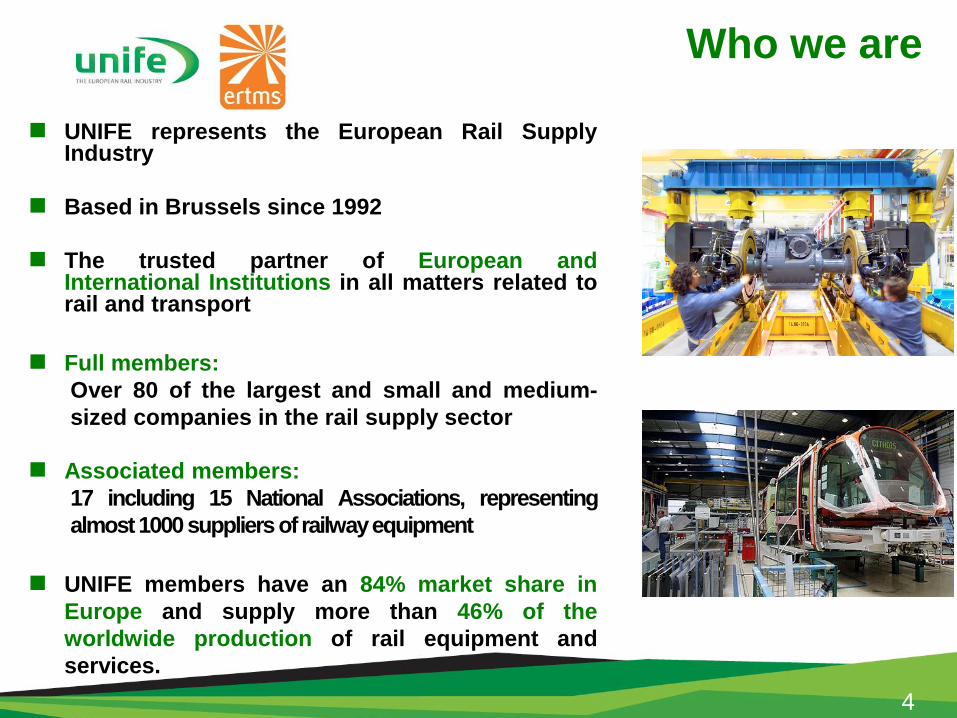
UNIFE represents the European Rail SupplyIndustry
Based in Brussels since 1992
The trusted partner of European andInternational Institutions in all matters related torail and transport
Full members:
Over 80 of the largest and small and medium-
sized companies in the rail supply sector
Associated members:
17 including 15 National Associations, representing
almost 1000 suppliers of railwayequipment
UNIFE members have an 84% market share in
Europe and supply more than 46% of the
worldwide production of rail equipment and
services.
4
UNIFE Members/ETCS Suppliers
5
The ERTMS/ETCS suppliers are gathered in the
UNISIG consortium
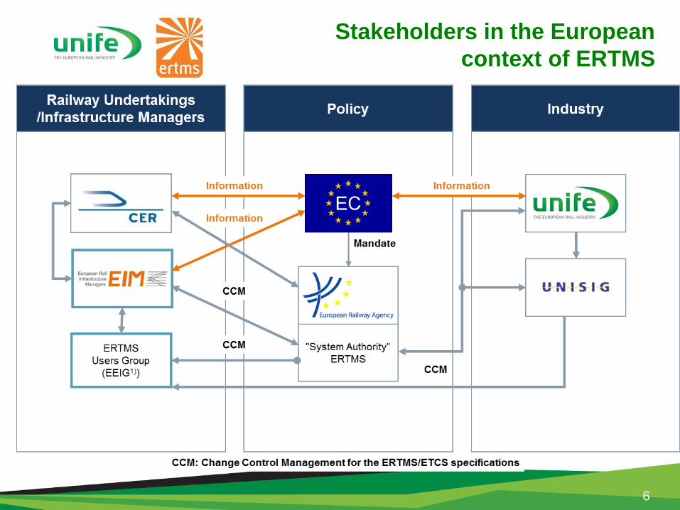
Stakeholders in the European
context of ERTMS
6
PTC & ETCS
7
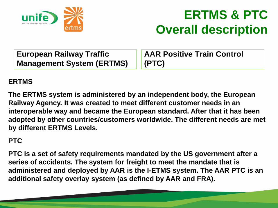
ERTMS & PTC
Overall description
European Railway Traffic
Management System (ERTMS)
AAR Positive Train Control
(PTC)
ERTMS
The ERTMS system is administered by an independent body, the European
Railway Agency. It was created to meet different customer needs in an
interoperable way and became the European standard. After that it has been
adopted by other countries/customers worldwide. The different needs are met
by different ERTMS Levels.
PTC
PTC is a set of safety requirements mandated by the US government after a
series of accidents. The system for freight to meet the mandate that is
administered and deployed by AAR is the I-ETMS system. The AAR PTC is an
additional safety overlay system (as defined by AAR and FRA).
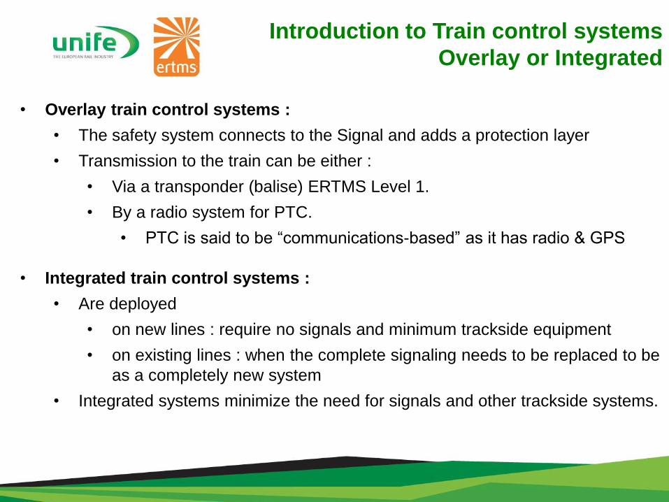
• Overlay train control systems :
• The safety system connects to the Signal and adds a protection layer
• Transmission to the train can be either :
• Via a transponder (balise) ERTMS Level 1.
• By a radio system for PTC.
• PTC is said to be “communications-based” as it has radio & GPS
• Integrated train control systems :
• Are deployed
• on new lines : require no signals and minimum trackside equipment
• on existing lines : when the complete signaling needs to be replaced to be
as a completely new system
• Integrated systems minimize the need for signals and other trackside systems.
Introduction to Train control systems
Overlay or Integrated
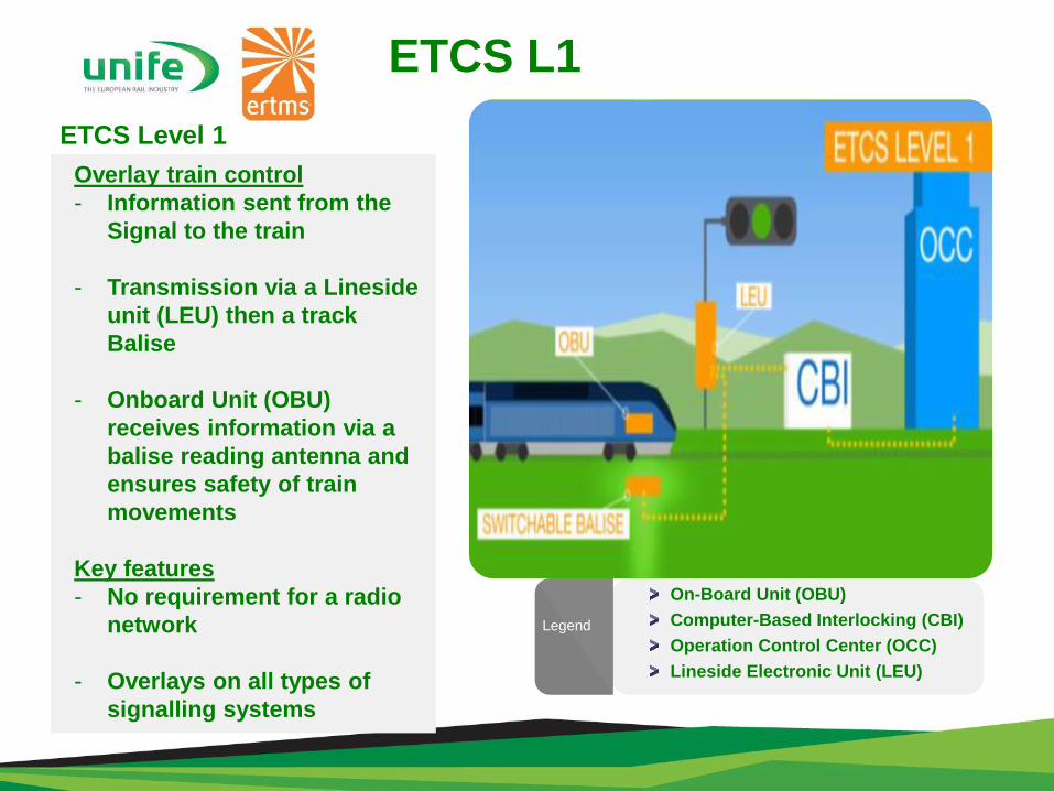
ETCS L1
ETCS Level 1
Overlay train control
- Information sent from the
Signal to the train
- Transmission via a Lineside
unit (LEU) then a track
Balise
- Onboard Unit (OBU)
receives information via a
balise reading antenna and
ensures safety of train
movements
Key features
- No requirement for a radio
network
- Overlays on all types of
signalling systems
On-Board Unit (OBU)
Computer-Based Interlocking (CBI)
Operation Control Center (OCC)
Lineside Electronic Unit (LEU)
Legend
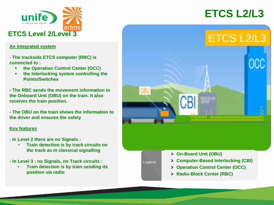
ETCS L2/L3
ETCS Level 2/Level 3
An integrated system
- The trackside ETCS computer (RBC) is
connected to :
the Operation Control Center (OCC)
the Interlocking system controlling the
Points/Switches
- The RBC sends the movement information to
the Onboard Unit (OBU) on the train. It also
receives the train position.
- The OBU on the train shows the information to
the driver and ensures the safety
Key features
- In Level 2 there are no Signals :
• Train detection is by track circuits on
the track as in classical signalling
- In Level 3 : no Signals, no Track circuits :
• Train detection is by train sending its
position via radio
On-Board Unit (OBU)
Computer-Based Interlocking (CBI)
Operation Control Center (OCC)
Radio-Block Center (RBC)
Legend
ETCS L2/L3
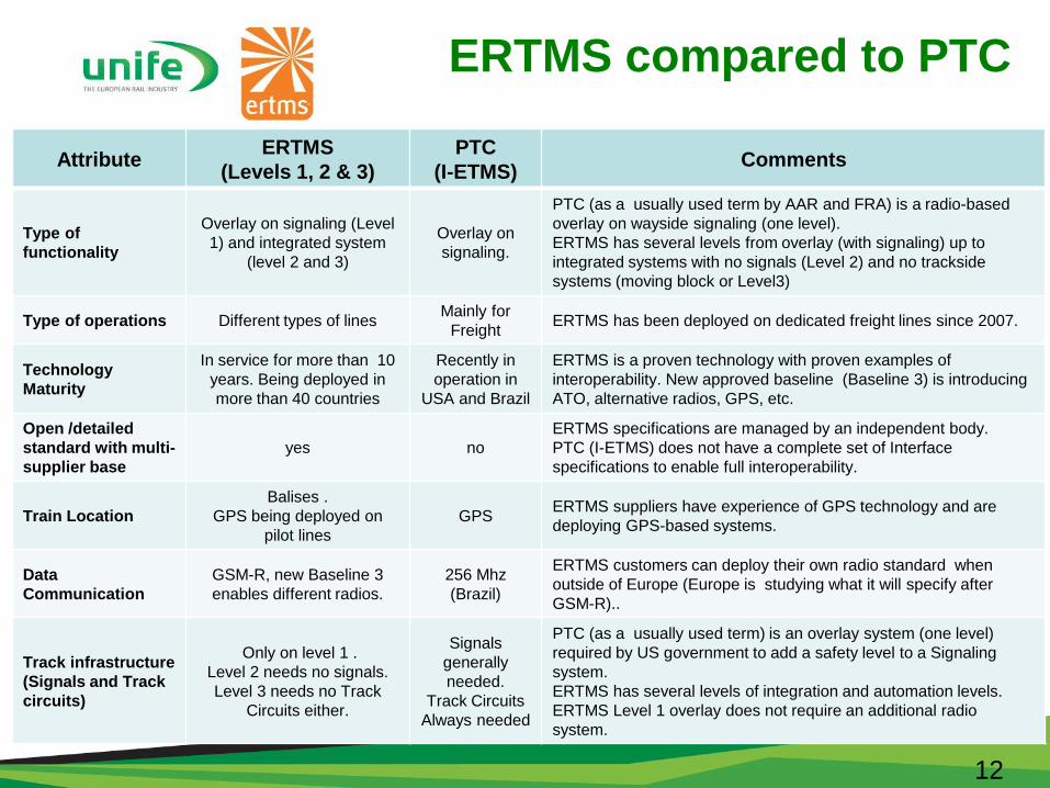
ERTMS compared to PTC
AttributeERTMS
(Levels 1, 2 & 3)
PTC
(I-ETMS)Comments
Type of
functionality
Overlay on signaling (Level
1) and integrated system
(level 2 and 3)
Overlay on
signaling.
PTC (as a usually used term by AAR and FRA) is a radio-based
overlay on wayside signaling (one level).
ERTMS has several levels from overlay (with signaling) up to
integrated systems with no signals (Level 2) and no trackside
systems (moving block or Level3)
Type of operations Different types of linesMainly for
FreightERTMS has been deployed on dedicated freight lines since 2007.
Technology
Maturity
In service for more than 10
years. Being deployed in
more than 40 countries
Recently in
operation in
USA and Brazil
ERTMS is a proven technology with proven examples of
interoperability. New approved baseline (Baseline 3) is introducing
ATO, alternative radios, GPS, etc.
Open /detailed
standard with multi-
supplier base
yes no
ERTMS specifications are managed by an independent body.
PTC (I-ETMS) does not have a complete set of Interface
specifications to enable full interoperability.
Train Location
Balises .
GPS being deployed on
pilot lines
GPSERTMS suppliers have experience of GPS technology and are
deploying GPS-based systems.
Data
Communication
GSM-R, new Baseline 3
enables different radios.
256 Mhz
(Brazil)
ERTMS customers can deploy their own radio standard when
outside of Europe (Europe is studying what it will specify after
GSM-R)..
Track infrastructure
(Signals and Track
circuits)
Only on level 1 .
Level 2 needs no signals.
Level 3 needs no Track
Circuits either.
Signals
generally
needed.
Track Circuits
Always needed
PTC (as a usually used term) is an overlay system (one level)
required by US government to add a safety level to a Signaling
system.
ERTMS has several levels of integration and automation levels.
ERTMS Level 1 overlay does not require an additional radio
system.
12
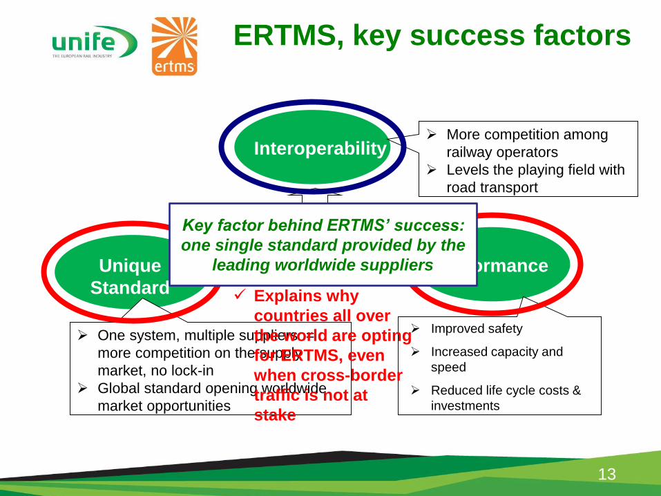
ERTMS, key success factors
13
Interoperability
ERTMS
PerformanceUnique
Standard
Improved safety
Increased capacity and
speed
Reduced life cycle costs &
investments
More competition among
railway operators
Levels the playing field with
road transport
One system, multiple suppliers =
more competition on the supply
market, no lock-in
Global standard opening worldwide
market opportunities
Explains why
countries all over
the world are opting
for ERTMS, even
when cross-border
traffic is not at
stake
Key factor behind ERTMS’ success:
one single standard provided by the
leading worldwide suppliers
ETCS LEVELS
GENERAL OVERVIEW
14
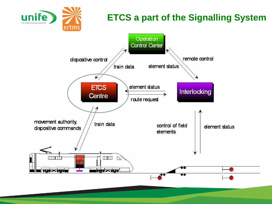
ETCS a part of the Signalling System
ETCS Level 1
System Overview
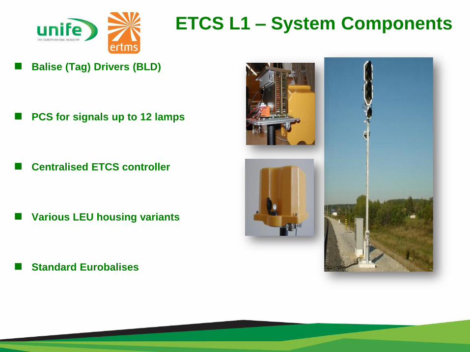
ETCS L1 – System Components
Balise (Tag) Drivers (BLD)
PCS for signals up to 12 lamps
Centralised ETCS controller
Various LEU housing variants
Standard Eurobalises

ETCS L1 – Decentralised solution
Lineside Electronic Unit (LEU)
installed at signal location
Consisting of :
BLDs
PWR
PIO / current sensors PCS
Coupling to adjacent LEUs
via parallel I/O
Balises (Tags)
▌ Interface between LEU and
signal via lamp circuit or relay
contact
InterlockingPWR
Balise
Cable
i/f C
Balise
BL
DB
LD
PW
R
BaliseBalise
BL
DB
LD
PWR Cable
Balise
BL
DB
LD
PW
R
PC
S
PC
S
PC
SP
WR
LEU LEU LEU
ELM
EuroloopJumper
Cable
Cable
i/f CL
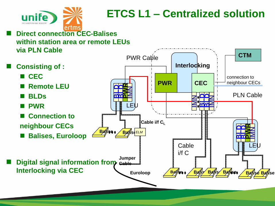
ETCS L1 – Centralized solution
Direct connection CEC-Balises
within station area or remote LEUs
via PLN Cable
Consisting of :
CEC
Remote LEU
BLDs
PWR
Connection to
neighbour CECs
Balises, Euroloop
Digital signal information from
Interlocking via CEC
Interlocking
PWR
Balise BaliseBalise
CEC
BL
DB
LD
IMN
Cable
i/f C
IMN
BaliseBalise
BL
DB
LD
IMN
PW
R
BaliseBaliseBalise
BL
DB
LD
IMN
PW
R
PLN Cable
PWR Cable
LEU
LEU
connection to
neighbour CECs
CTM
ELM
Euroloop
Jumper
Cable
Cable i/f CL
ETCS L2 & L3
System Overview
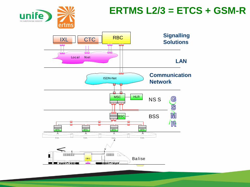
ERTMS L2/3 = ETCS + GSM-R
BSC
5 km 5 km 5 km5 km
ISDN-Net
RBC
HLR
BTS
OBU Ba lise
BTS BTS BTS
MSC
BSS
NS S
Lo a l N et
IXL CTC
Communication
Network
Signalling
Solutions
LANc
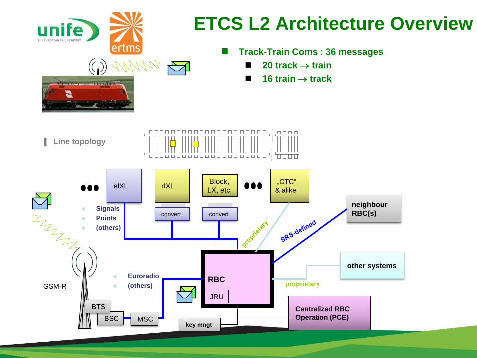
ETCS L2 Architecture Overview
Track-Train Coms : 36 messages
20 track train
16 train track
▌ Line topology
RBCGSM-R
BSC
rIXLBlock,
LX, etceIXL
convert convert
key mngt
JRU
„CTC“
& alike
Centralized RBC
Operation (PCE)
other systems
neighbour
RBC(s) Signals
Points
(others)
Euroradio
(others) proprietary
MSC
BTS
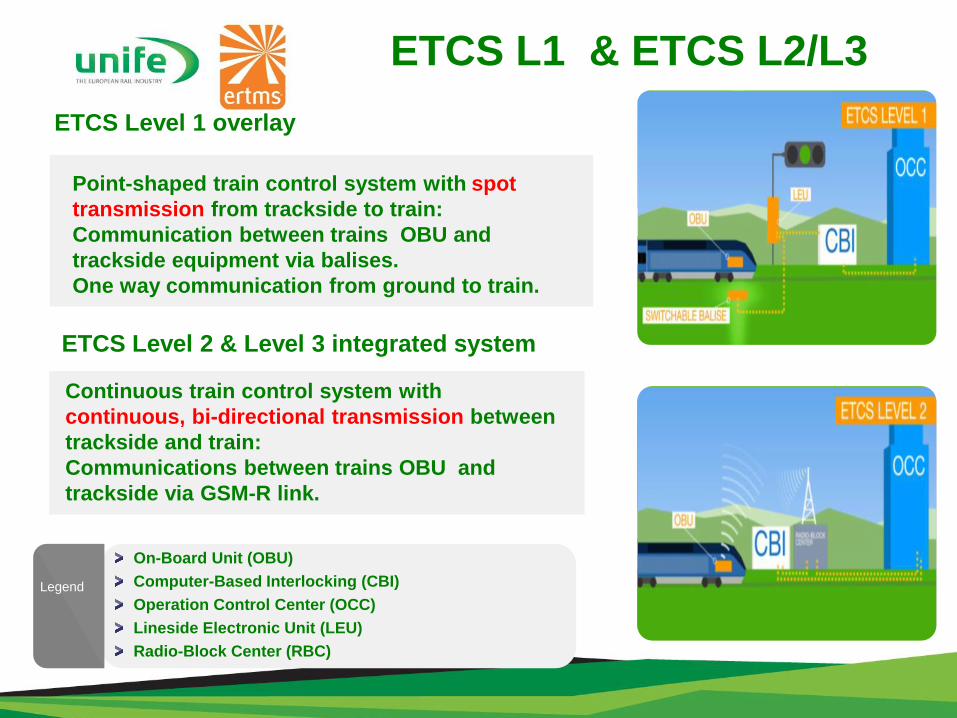
ETCS L1 & ETCS L2/L3
ETCS Level 1 overlay
Point-shaped train control system with spot
transmission from trackside to train:
Communication between trains OBU and
trackside equipment via balises.
One way communication from ground to train.
ETCS Level 2 & Level 3 integrated system
Continuous train control system with
continuous, bi-directional transmission between
trackside and train:
Communications between trains OBU and
trackside via GSM-R link.
On-Board Unit (OBU)
Computer-Based Interlocking (CBI)
Operation Control Center (OCC)
Lineside Electronic Unit (LEU)
Radio-Block Center (RBC)
Legend

Case study
North South Rail Link, Saudi Arabia
North South
Rail link in
Saudi Arabia
The world’s longest
ETCS line
ERTMS EXAMPLES & SYSTEM
EVOLUTION
25

Further develop the Kingdom by
developing the non oil mineral
capacities.
Create: A freight line linking phosphate and
bauxite production plants in the northern part of the kingdom to industrial complex along the Arabian gulf.
Passenger services from Riyadh to the North of Saudi-Arabia.
A turnkey solution based on advanced
signalling and telecom technology.
Customer challenges
Case study
North South Rail Link, Saudi Arabia
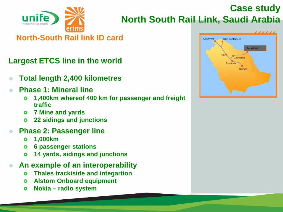
Largest ETCS line in the world
Total length 2,400 kilometres
Phase 1: Mineral line 1,400km whereof 400 km for passenger and freight
traffic
7 Mine and yards
22 sidings and junctions
Phase 2: Passenger line 1,000km
6 passenger stations
14 yards, sidings and junctions
An example of an interoperability Thales trackiside and integartion
Alstom Onboard equipment
Nokia – radio system
North-South Rail link ID cardRas AlKhair
Case study
North South Rail Link, Saudi Arabia
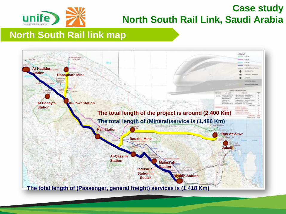
North South Rail link map
Al-Basayta
Station
Jubail
Riyadh Station
Al-Haditha
Station
Majma’ah
StationIndustrial
Station in
Sudair
Al-Qassim
Station
Bauxite Mine
Hail Station
Al-Jowf Station
Phosphate Mine
Ras Az Zawr
The total length of the project is around (2,400 Km)
The total length of (Mineral)service is (1,486 Km)
The total length of (Passenger, general freight) services is (1,418 Km)
Case study
North South Rail Link, Saudi Arabia
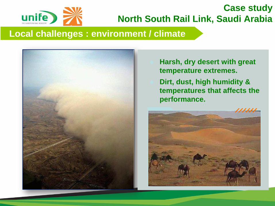
Harsh, dry desert with great
temperature extremes.
Dirt, dust, high humidity &
temperatures that affects the
performance.
Local challenges : environment / climate
Case study
North South Rail Link, Saudi Arabia
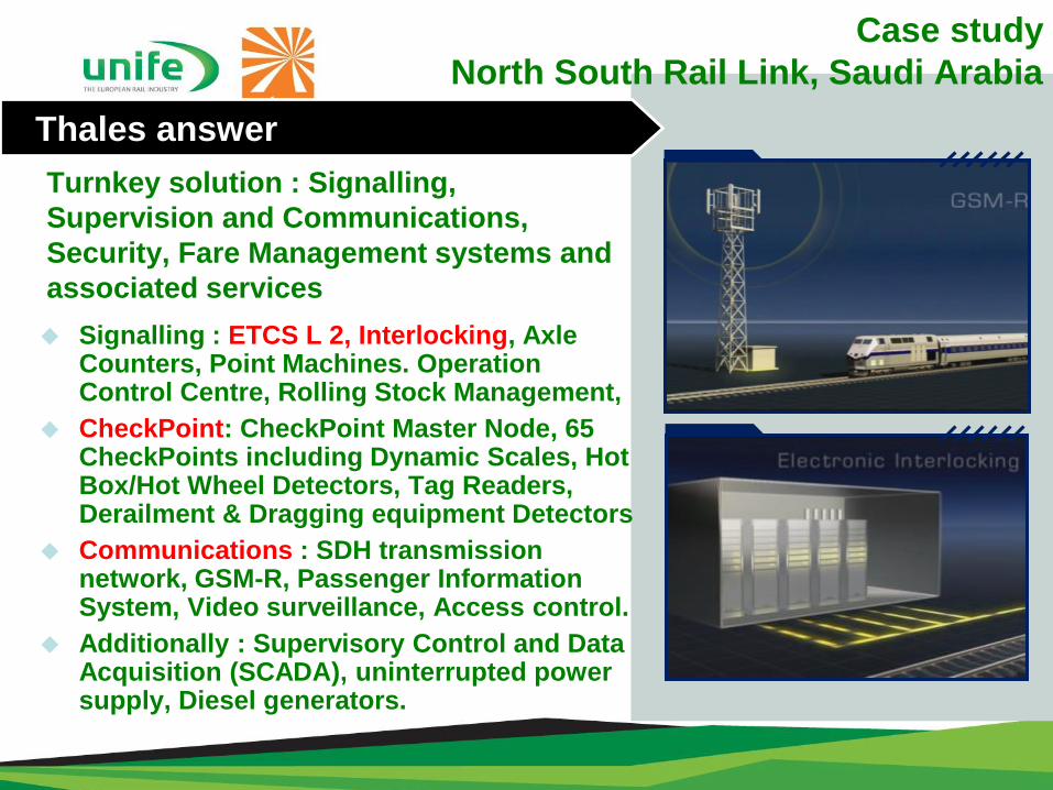
Turnkey solution : Signalling,
Supervision and Communications,
Security, Fare Management systems and
associated services
Thales answer
Signalling : ETCS L 2, Interlocking, Axle Counters, Point Machines. Operation Control Centre, Rolling Stock Management,
CheckPoint: CheckPoint Master Node, 65 CheckPoints including Dynamic Scales, Hot Box/Hot Wheel Detectors, Tag Readers, Derailment & Dragging equipment Detectors
Communications : SDH transmission network, GSM-R, Passenger Information System, Video surveillance, Access control.
Additionally : Supervisory Control and Data Acquisition (SCADA), uninterrupted power supply, Diesel generators.
Case study
North South Rail Link, Saudi Arabia
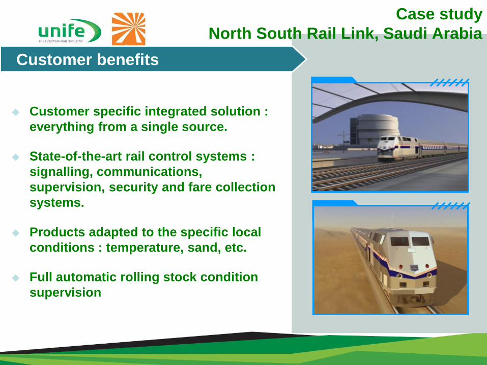
Customer benefits
Customer specific integrated solution :
everything from a single source.
State-of-the-art rail control systems :
signalling, communications,
supervision, security and fare collection
systems.
Products adapted to the specific local
conditions : temperature, sand, etc.
Full automatic rolling stock condition
supervision
Case study
North South Rail Link, Saudi Arabia
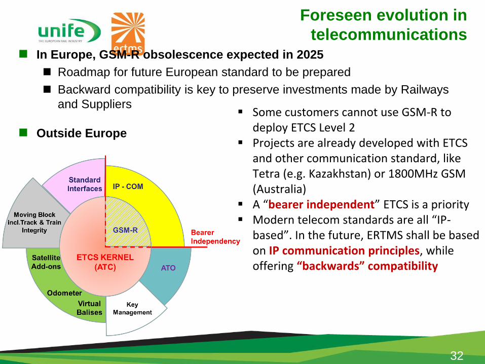
Foreseen evolution in
telecommunications In Europe, GSM-R obsolescence expected in 2025
Roadmap for future European standard to be prepared
Backward compatibility is key to preserve investments made by Railways
and Suppliers
Outside Europe
32
Some customers cannot use GSM-R to deploy ETCS Level 2
Projects are already developed with ETCS and other communication standard, like Tetra (e.g. Kazakhstan) or 1800MHz GSM (Australia)
A “bearer independent” ETCS is a priority Modern telecom standards are all “IP-
based”. In the future, ERTMS shall be based on IP communication principles, while offering “backwards” compatibility
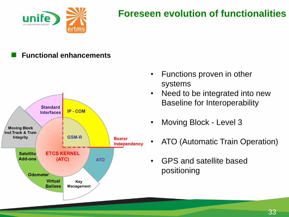
Foreseen evolution of functionalities
Functional enhancements
33
• Functions proven in other
systems
• Need to be integrated into new Baseline for Interoperability
• Moving Block - Level 3
• ATO (Automatic Train Operation)
• GPS and satellite based
positioning
CONCLUSION
34
Key takeaways (1/2)
ERTMS was designed for highest availability and safety:
High-end safety (SIL 4)
Safe operator terminal
CENELEC standards
ERTMS protects investments by:
Easy integration in new or existing environments
High scalability from small to large topologies
Integration of leading edge technologies
(Packet Switched Radio)
Lower maintenance costs (standard equipment)
Constant evolution (L3)
Key takeaways (2/2)
ERTMS increases capacity through ETCS L1 or L2
Supports the seamless integration to all kinds of interlocking
systems:
existing or new infrastructure
other NRBC providers
Seamless integration and interoperability with other suppliers
Compact RBC for all kinds of traffic:
High Speed
Mainline
Urban
Freight

Thank you for your attention
www.unife.org
www.ertms.net
@UNIFE
@ERTMS


