Pitch Detection Embedded System Design Final Report Due May 10, 2005 -- Stephen A. Edwards Embedded Systems Design, 2005 -- Koohee Lee ([email protected]) Guy Sivan ([email protected]) Gary Lo ([email protected])
1. Project Overview Our final product was targeted towards users that were in the early stages of learning a new and foreign language. In many foreign languages, especially some of the South East Asian ones, the accuracy of a speaker’s pronunciation is highly dependant upon their ability to create the correct pitch and tone. To this end, it was our desire to create a system that would allow a user to visualize their own voice patterns and make corrections based on their own observations. Our design was to create a hardware/software combination that would allow a user to see a plot of pitch versus time in a real-time format. For simplicity let us assume that a voice consists of a single sinusoid. To find the pitch or frequency at a certain point in time, one can just look closely (zoom into) a waveform and measure the distance between to successive peaks. This distance corresponds to the period o the voice, and so to find the frequency, we just need to take the reciprocal of this value. This is the fundamental concept of our algorithm. In the real world, a voice consists of many sinusoids rather than just one pure sinusoid. These sinusoids are a result of the anatomy of the human vocal system and appear all over the frequency spectrum (at many different frequencies). We have a much more complicated signal that consists of the fundamental harmonic and many other harmonics. The fundamental harmonic is the main frequency and it is what we define as the “pitch” of the voice. Our project is to find exactly this, and to plot it in real-time to get a graphical view of how the pitch in someone’s voice is changing.
2. Project Design Prototype
We created an initial prototype that would execute in Matlab. The goal of the prototype was to determine the feasibility of our project, as well as prove that our algorithm actually worked as planned. The Matlab program was created based on an initial algorithm that we designed which has since been modified to increase performance.
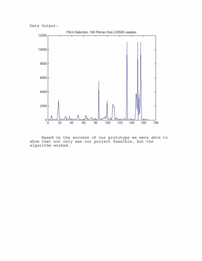
The input to our program was Koohee’s voice, which was taken in through a microphone and stored. This data was processed and outputted the following graph. Data Input:
Data Output:
Based on the success of our prototype we were able to show that not only was our project feasible, but the algorithm worked.
Finalized Algorithm The first step is to take in the sound wave. The A/D will take a signal from the microphone and output a 16bit digital signal at 11kHz, which will be shifted into a shift register the size of one block (330 samples). Every 330 samples, the contents of the shift register will be copied into a buffer. The contents in this buffer are what we run our algorithm on to determine a single value on the output of the pitch graph. To run the algorithm, the first step is to perform a half-autocorrelation on the data set in the input buffer. The result of this autocorrelation will allow us to determine the distance between the two peaks in a time block because they will correspond to the two largest peaks in the autocorrelation. Performing this process one the data from the buffer will leave us with a new set of 330 points of data, the “half-autocorrelation graph”. This data is then processed as follows to find the distance between the peaks.
1. Take the derivative of the data. 2. Perform the sign function on the data from step 1. 3. Take the derivative of data from step 2 and multiply by
-1. 4. Remove negative zero crossings. 5. Multiply results from step 4 with data in half-
autocorrelation graph one data point at a time and store in new buffer (or same buffer as step 4 to save space.)
6. (May not be necessary:) Remove first few points from result in step 5.
7. Find the first peak and record its index in the buffer. 8. Use the index from step 7 and the block specifications
to find the distance between nearest peaks and calculate value in time (period) and corresponding frequency (pitch): Period = T = (index / (samples per block)) * (block time), Pitch = f = 1 / T
9. Output the pitch
Block Diagram of Algorithm.
3. Design Components Hardware Design
Our plan was to do three things inside hardware:
1. We wanted to take in voice data from a microphone and store it in the SRAM. This required using the audio codec to digitize the analog data from our voices.
2. Next we needed to extract data from the SRAM and pass it to the C program for processing.
3. Incorporate video controller from previous lab to get output onto the screen after processing inside C program.
What we were able to do:
1. We were able to create VHDL code that would allow us to write data into the SRAM from a microphone.
2. We were unable to determine how to get data stored inside the SRAM and send it to the Microblaze and our C program.
Software Design We used C to process the data that was passed to the Microblaze from the SRAM. This process contained several steps:
1. Perform half-autocorrelation of data. 2. Take the first derivative. 3. Classify them into {-1, 0, 1} as the sign. 4. Find out zero-crossing. 5. Remove positive one’s. 6. Flip the sign. 7. Multiply them by the data from step 1. 8. Find the maximum value and its location. 9. Return the pitch of the processing block.
a. (Sampling frequency) / (STEP * pitch location) The C program proves to work like the Matlab program, but is currently implemented using floating point. It must be modified to work with the data stored in the SRAM (non-floating point data). We need to reduce the input size of the data by dividing it by a constant to ensure that overflow of output data from half-autocorrelation does not occur.
Calculations
We had to conduct several calculations to determine the feasibility of our project given our algorithm and the available hardware.
Given:
10. CPU with clock speed of 50Mhz. 11. Audio sampling device at 11kHz. 12. A/D converter with 16 bit output. 13. Human Voice ~ (100Hz to 1000Hz).
Clock Cycle Calculation (Half-Autocorrelation) orig_n = 330 n = 165 Total number of multiplications = n(2n-1): = 165*(330-1) = 54285 Total number of additions = (n-1)(2n-1): = (165-1)(330-1)
= 53956 Clock cycles for addition: 1 Clock cycles for multiplication: 5 Total clock cycles requires: = 1*(54285) + 5*(53956) = 324056 Process running at 50Mhz, implies a time per clock cycles of: = 1 / 50Mhz = 2*10-8 seconds per cycle Therefore, total time for half-autocorrelation: = 324065 * (2*10-8) = 6.4813 ms
This number is well within our range of 30ms per time block.
Block Size Calculation In order to calculate the pitch, we need at least two peaks to be within the block we are measuring the pitch of. Given that the block will not always perfectly align with the waveform, the only way we can ensure that at least two peaks are within the block is to set the block size to three wavelengths of the lowest possible frequency. As mentioned earlier we chose the lowest possible frequency to be 100Hz. 1/(100Hz) = 10ms, 3*10ms = 30ms,
At a sampling frequency of 11kHz: (11kHz)*(30ms) = 330 samples,
Block Size = 30ms, 330 samples. Note: The actual sampling rate of the codec was 44kHz, so we had to decimate the input to simulate 11kHz (1 out of every 4 samples).
5. Work Distribution Koohee Lee
o Rewrote full algorithm in Matlab for prototyping, verification and fine-tuning.
o Used Matlab to create samples and diagrams to prove that our algorithm worked.
o In charge of creating the C code to implement DSP. o Worked together to write final project report.
Guy Sivan
o Full system design. o In charge of VHDL programming. o Designed signal processing algorithm for pitch
detection. o Reviewed details of DSP for timing and feasibility
calculations. o Researched and studied datasheets for necessary
hardware components. o Worked together to write final project report.
Gary Lo
o Reviewed details of DSP for timing and feasibility calculations.
o Modified signal processing algorithm for increased efficiency; including the idea of the half-autocorrelation concept.
o Researched and studied datasheets for necessary hardware components.
o Worked together to write final project report. o Involved in coding for both VHDL and C.
6. Future Advice and Lessons Learned Every member of the group felt that if we had coordinated and managed our time more skillfully we would have been able to finish our project. Our inability to be disciplined about our meeting times caused two problems:
1. We were unable to meet with our advisor (Marcio) as often as we would have liked to discuss our project.
2. We were forced to create all of our VHDL code in a very hasty manner in order to try and generate some final result.
As it is now, we believe that with another week or two of
work we could have the project fully completed.
Although we were unable to create a finished working product, we did do several things correctly. By rigorously testing and prototyping our algorithm in both Matlab and C were able to prove that our design would work. Also, the time spent modifying our algorithm meant that it was even more efficient than we had initially expected it to be.
In the future, we would recommend that if it is
difficult to find a specific time where all members of the group are able to meet, start by using the class time as a meeting time because all group members will always be available during this time. We also recommend that people start early, create a detailed plan, and modularize the project so that individuals in the group could be responsible for their own part of the project.
7. VHDL ------------------------------------------------------------------------------- -- REAL-TIME PITCH DETECTION ------------------------------------------------------------------------------- library ieee; use ieee.std_logic_1164.all; use IEEE.STD_LOGIC_ARITH.all; use IEEE.STD_LOGIC_UNSIGNED.all; entity pd is generic ( C_OPB_AWIDTH : integer := 32; C_OPB_DWIDTH : integer := 32; C_BASEADDR : std_logic_vector(0 to 31) := X"00000000"; C_HIGHADDR : std_logic_vector(0 to 31) := X"FFFFFFFF" ); port ( OPB_Clk : in std_logic; OPB_Rst : in std_logic; OPB_ABus : in std_logic_vector(0 to C_OPB_AWIDTH-1); --(31:0) OPB_BE : in std_logic_vector(0 to C_OPB_DWIDTH/8-1);--(3:0) OPB_DBus : in std_logic_vector(0 to C_OPB_DWIDTH-1); --(31:0) OPB_RNW : in std_logic; OPB_select : in std_logic; OPB_seqAddr : in std_logic; -- Sequential Address Sln_DBus : out std_logic_vector(0 to C_OPB_DWIDTH-1); --(31:0) Sln_errAck : out std_logic; -- (unused) Sln_retry : out std_logic; -- (unused) Sln_toutSup : out std_logic; -- Timeout suppress Sln_xferAck : out std_logic; -- Transfer acknowledge SRAM_CE : out std_logic; --sram chip enable (active low) SRAM_OE : out std_logic; --sram output enable (active low) SRAM_WE : out std_logic; --sram write enable (active low) SRAM_UB : out std_logic; --sram enable upper-byte(active low) SRAM_LB : out std_logic; --sram enable lower-byte(active low) PB_A : out std_logic_vector(17 downto 0); --sram 18 bit address PB_D : inout std_ulogic_vector(15 downto 0); --sram 16 bit data
-- G: For audio codec -- au_mclk : out std_logic; au_lrclk : out std_logic; au_bclk : out std_logic; au_sdti : out std_logic; au_sdto0 : in std_logic; au_cs : out std_logic ); end pd; ------------------------------------------------------------------------------- architecture Behavioral of pd is ----------------------------------------------------------------------------- -- SRAM ----------------------------------------------------------------------------- constant RAM_AWIDTH : integer := 18; -- Number of address lines on the RAM constant RAM_DWIDTH : integer := 16; -- Number of data lines on the RAM component OBUF_F_24 port ( O : out STD_ULOGIC; -- the pin I : in STD_ULOGIC); -- signal to pin end component; component IOBUF_F_24 port ( O : out STD_ULOGIC; -- signal from pin IO : inout STD_ULOGIC; -- the pin I : in STD_ULOGIC; -- signal to pin T : in STD_ULOGIC); -- 1-drive IO with I end component; ------------------------------------------------------------------------------- -- Audio Controller ------------------------------------------------------------------------------- component wr_audio_control port ( clk_in: in std_logic; -->200ns clock
init: in std_logic; --pulse input done: out std_logic; D_in: in std_logic_vector(15 downto 0); --control data cntrl_out: out std_logic); end component; ------------------------------------------------------------------------------ -- Codec ------------------------------------------------------------------------------ component ak4565 port ( clk : in std_logic; rst : in std_logic; mclk : out std_logic; bclk : out std_logic; lrclk : out std_logic; sdti : out std_logic; sdto0 : in std_logic; csn : out std_logic; cclk : out std_logic; cdti : out std_logic; adcdone : out std_logic; --AD indicator dacload : out std_logic; --DA indicator --G: UNUSED adc_dtout : out std_logic_vector(15 downto 0); --data out to fpga dac_dtin : in std_logic_vector(15 downto 0); --parallelload data from fpga c_datain : in std_logic_vector(15 downto 0); --parallelload control from fpga c_wr : in std_logic :='0'; --write to control c_done : out std_logic --write control done ); end component; ------------------------------------------------------------------------------- -- SIGNALS ------------------------------------------------------------------------------- signal mclk : std_logic; --12.5Mhz signal bclk : std_logic; --3.125Mhz signal lrclk: std_logic; --48.8Khz signal cclk: std_logic; signal sdti: std_logic;
signal latch16bit: std_logic_vector(15 downto 0) := x"0000"; signal adcdone : std_logic; signal dacload : std_logic; --G: UNUSED signal adc_dtout : std_logic_vector(15 downto 0); --data out to fpga signal dac_dtin : std_logic_vector(15 downto 0) :=x"0000"; --parallelload data from fpga --G: UNUSED signal c_datain : std_logic_vector(15 downto 0) :="1110000011100111"; --parallelload control from fpga signal csn : std_logic; signal c_wr : std_logic; signal c_done : std_logic; signal trigger : std_logic; ------------------------------------------------------------------------------- --SRAM signal tri_state : std_logic; --tristate signal ABus: std_logic_vector(17 downto 0); --Abus --always equal to sram_addr signal pbDIn: std_logic_vector(15 downto 0); --RAM_DI --is equal to sram_dt_wr when c_state=norm --else is all zeroes signal sram_rnw: std_logic; --RNW signal sram_addr: std_logic_vector(17 downto 0); --Abus signal sram_dt_rd: std_logic_vector(15 downto 0); --RAM_DO signal sram_dt_wr: std_logic_vector(15 downto 0); --connects to pbDIn when c_state=norm -- G added: signal chip_select : std_logic; signal output_enable, write_enable : std_logic; signal upperbyte_enable, lowerbyte_enable : std_logic; signal RNW : std_logic; signal RST : std_logic; -- G added: some more stuff (for SRAM to be OPB readable (?))-- -- Critical: Sln_xferAck is generated directly from state bit 0!
constant STATE_BITS : integer :=3; constant Idle : std_logic_vector(0 to STATE_BITS-1) := "000"; constant Selected : std_logic_vector(0 to STATE_BITS-1) := "001"; constant Read : std_logic_vector(0 to STATE_BITS-1) := "011"; constant Xfer : std_logic_vector(0 to STATE_BITS-1) := "111"; signal present_state, next_state : std_logic_vector(0 to STATE_BITS-1); ----------------------------------------------------------------------------- signal initcnt:std_logic_vector(15 downto 0):=X"0000"; --has to wait > 4128/fs=90ms for initialization constant pre_init : std_logic_vector(1 downto 0):="00"; constant c_wr_wait: std_logic_vector(1 downto 0):="01"; constant wait_done: std_logic_vector(1 downto 0):="10"; constant norm : std_logic_vector(1 downto 0):="11"; signal c_state, n_state : std_logic_vector(1 downto 0):="00"; --used in both FSMs signal c_serial_data: std_logic; --used for FSM that controls writing audio data to memorys constant idling : std_logic_vector(1 downto 0):="00"; constant s1: std_logic_vector(1 downto 0):="01"; constant s2 : std_logic_vector(1 downto 0):="10"; signal s_done : std_logic; --when done writing to SRAM ------------------------------------------------------------------------------ --G: added: (THESE SIGNALS WILL HELP COORDINATE WHO IS READING AND WRITING, but they are not yet used fully) signal audio_wr_addr: std_logic_vector(17 downto 0):="000000000000000000"; --the pointer to where the --current audio sample --should be written to in SRAM signal en_MB_read: std_logic; --used to disable the microblaze from --reading when the data from codec is --being written to SRAM. signal MB_read_addr: std_logic_vector(17 downto 0); --the current address where the --Microblaze reads from. ------------------------------------------------------------------------------- begin
------Audio Interface Signals and Buffering-------------------------------------------------- au_mclk <= mclk; -----VERY IMPORTANT---- mclk must be sync with LRCLK au_bclk <= bclk; au_lrclk<= lrclk; au_sdti <= sdti; au_cs <=csn; ------SRAM pin assignment----------------------------------------------------------------------- SRAM_CE <= '0' when chip_select = '1' else '1'; -- '0' when c_state=norm else1? SRAM_WE <= '0' when write_enable = '1' else '1'; SRAM_OE <= '0' when output_enable = '1' else '1'; --sram_rnw? SRAM_UB <= '0' when upperbyte_enable = '1' else '1'; SRAM_LB <= '0' when lowerbyte_enable = '1' else '1'; gen1: for m in 0 to 17 generate sramAddrpin:OBUF_F_24 port map ( O=>PB_A(m), I=>ABus(m)); end generate; gen2: for m in 0 to 15 generate sramDatapin:IOBUF_F_24 port map ( O=>sram_dt_rd(m), IO=>PB_D(m), I=>pbDIn(m), T=>tri_state); end generate; --G: we have to change this:---------------------------------------- tri_state <=sram_rnw when c_state=norm else '0'; --always writing ABus<=sram_addr(17 downto 0); pbDIn(15 downto 2) <= sram_dt_wr(15 downto 2) when c_state=norm else (others => '0'); pbDIn(0)<=sram_dt_wr(0) when c_state=norm else cclk; pbDIn(1)<=sram_dt_wr(1) when c_state=norm else c_serial_data; -------------------------------------------------------------------- chip_select <=
'1' when OPB_select = '1' and OPB_ABus(0 to C_OPB_AWIDTH-2-RAM_AWIDTH) = C_BASEADDR(0 to C_OPB_AWIDTH-2-RAM_AWIDTH) else '0'; ------------------------------------------------------------------------------- --The code below is from Lab6 and is for making the Microblaze be able to --read from the SRAM. This way we can get the incoming audio data into the C- --code and do the signal processing in C. It seems that although C is much --slower than doing it in hardware, there is enough speed to keep up real- --time with much decimation (i.e. skipping output points). This just means a --less smooth output. -- Sequential part of the FSM fsm_seq : process(OPB_Clk, OPB_Rst) begin if OPB_Rst = '1' then present_state <= Idle; elsif OPB_Clk'event and OPB_Clk = '1' then present_state <= next_state; end if; end process fsm_seq; -- Combinational part of the FSM fsm_comb : process(OPB_Rst, present_state, chip_select, OPB_Select, RNW) begin RST <= '1'; write_enable <= '0'; output_enable <= '0'; upperbyte_enable <= '1'; lowerbyte_enable <= '1'; tri_state <= '0'; -- used to be "tristate" if OPB_RST = '1' then next_state <= Idle; else case present_state is when Idle => if chip_select = '1' then next_state <= Selected; else next_state <= Idle;
end if; when Selected => if OPB_Select = '1' then if RNW = '1' then RST <= '0'; next_state <= Read; else write_enable <= '1'; tri_state <= '0'; next_state <= Xfer; end if; else next_state <= Idle; end if; when Read => if OPB_Select = '1' then output_enable <= '1'; tri_state <= '1'; next_state <= Idle; end if; -- State encoding is critical here: xfer must only be true here when Xfer => next_state <= Idle; when others => next_state <= Idle; end case; end if; end process fsm_comb; Sln_xferAck <= present_state(0); ------------------------------------------------------------------------------- -- Audio codec port map ------------------------------------------------------------------------------- ak:ak4565 port map(clk =>OPB_Clk,
rst =>OPB_Rst, mclk =>mclk, bclk =>bclk, lrclk =>lrclk, sdti =>sdti, sdto0 =>au_sdto0, csn =>csn, cclk =>cclk, cdti =>c_serial_data, adcdone =>adcdone, dacload =>dacload, adc_dtout => adc_dtout, dac_dtin => dac_dtin, c_datain =>c_datain, c_wr =>c_wr, c_done =>c_done); ------------------------------------------------------------------------------- -- PROCESSES ------------------------------------------------------------------------------- ---latch output data---------------------- (from codec) process (OPB_Clk,OPB_Rst) begin if OPB_Rst = '1' then latch16bit<=x"0000"; elsif OPB_clk'event and OPB_clk ='1' then if adcdone = '1' then --and dacload = '1' then --G: don't need latch16bit(15 downto 0)<=adc_dtout(15 downto 0); end if; end if; end process; ------------------------------------------------------------------------------- --G:added --Write the latched data to the SRAM, but divide by 2 first. process(OPB_Clk, OPB_Rst) begin if OPB_Rst='1' then sram_dt_wr(15)<=latch16bit(15); sram_dt_wr(14)<=latch16bit(15); sram_dt_wr(13)<=latch16bit(14); sram_dt_wr(12)<=latch16bit(13);
sram_dt_wr(11)<=latch16bit(12); sram_dt_wr(10)<=latch16bit(11); sram_dt_wr(9)<=latch16bit(10); sram_dt_wr(8)<=latch16bit(9); sram_dt_wr(7)<=latch16bit(8); sram_dt_wr(6)<=latch16bit(7); sram_dt_wr(5)<=latch16bit(6); sram_dt_wr(4)<=latch16bit(5); sram_dt_wr(3)<=latch16bit(4); sram_dt_wr(2)<=latch16bit(3); sram_dt_wr(1)<=latch16bit(2); sram_dt_wr(0)<=latch16bit(1); --sram_dt_wr(14 downto 0)<=latch16bit(15 downto 1); end if; end process; --fsm of delay process----- process(OPB_Clk,OPB_Rst) begin if OPB_Rst='1' then c_state<=idling; elsif OPB_Clk'event and OPB_Clk='1' then c_state<=n_state; end if; end process; --state machine combinational logic FSM_Comb_wr_to_SRAM: process(OPB_Rst,trigger,c_state) begin sram_rnw<='1'; --always reading s_done<='0'; if rst='1' then n_state <= idling; else case c_state is when idling => if trigger='1' then n_state<=s1; else n_state<=idling; end if; when s1 => --wait for calculation to be done
n_state<=s2; when s2 => --store new data to SRAM sram_rnw<='0'; --write to sram s_done<='1'; n_state<=idling; when others => n_state<=idling; end case; end if; end process; --generate current address for writing or MB_reading. process(OPB_Clk,OPB_Rst) begin if rst='1' then sram_addr<="000000000000000000"; --sr_addr<="000101110111000000"; --starts at 24000 elsif OPB_Clk'event and OPB_Clk='1' then if c_state=s1 then sram_addr<=audio_wr_addr; else sram_addr<=MB_read_addr; --GUY: NO NEED (?) end if; end if; end process; --G: NOTE c_addr was changed to audio_wr_addr; --update current SRAM address -- process(OPB_Clk,OPB_Rst) begin if OPB_Rst='1' then audio_wr_addr <="000000000000000000"; --24000, 1/2sec delay elsif OPB_Clk'event and OPB_Clk='1' then audio_wr_addr <= audio_wr_addr + 1; end if; end process; ------------------------------------------------------------------------------- --GUY: --- generate trigger for writing into SRAM when audio data is ready---------- -- disables MicroBlaze from reading while data is being written to SRAM------
process (OPB_Clk,OPB_Rst) begin if OPB_Rst = '1' then trigger<='0'; en_MB_read <= '0'; elsif OPB_clk'event and OPB_clk ='1' then if adcdone = '1' then trigger<='1'; en_MB_read <= '0'; else trigger<='0'; en_MB_read <= '1'; end if; end if; end process; ----control initialization for audio codec------- --op0 op1 op2 a0 a1 a2 a3 a4 d0 d1 d2 d3 d4 d5 d6 d7 c_datain<= "1110000000100000"; --c_datain<= "1110100010001000"; process (bclk, OPB_Rst) begin if OPB_Rst = '1' then c_state <= pre_init; elsif bclk'event and bclk='1' then c_state<=n_state; end if; end process; process (lrclk, OPB_Rst) begin if OPB_Rst = '1' then initcnt <= X"0000"; elsif lrclk'event and lrclk='1' then initcnt <= initcnt + 1; end if; end process; process (initcnt(15),c_state,c_done) begin c_wr<='0'; case c_state is when pre_init =>
--wait for initcnt if initcnt(15) = '1' then n_state<=c_wr_wait; else n_state<=pre_init; end if; when c_wr_wait => --hold c_wr for 1 cycle c_wr<='1'; n_state<=wait_done; when wait_done => if c_done='1' then --normal operation n_state<=norm; else n_state<=wait_done; end if; when norm => n_state<=norm; when others => n_state<=pre_init; end case; end process; end Behavioral;
8. C //This code still needs to be modified so that the input will be from //the SRAM rather than a file. Also, all data will have to be converted //to int or short type (instead of float). #include <stdio.h> #include <stdlib.h> #define FREQ 44100 /* sampling frequency */ #define BLOCKSIZE 330 /* size of one processing block */ #define STEP 4 /* */ #define Delta 0.001 /* for derivative */ int main(void) { FILE *fp, *fout; int i, j, index, length, position; int k = 0; float tempval; float *tempdata; float data[BLOCKSIZE]; float temp; float output[BLOCKSIZE]; float diff[BLOCKSIZE]; float zerocross[BLOCKSIZE]; float maxima[BLOCKSIZE]; char ch[BLOCKSIZE * STEP]; int itr = 0; /* Read data from voice file */ if ((fp = fopen("sample.txt", "r")) == NULL) fprintf(stderr, "Cannot open %s\n", "sample.txt"); /* The whole voice data; Will be limited by the RAM size */ tempdata = (float *) calloc(220500, sizeof(float)); /* 220500 as (BLOCKSIZE * STEP) * One processing block. */
/* Write the voice file into tempdata */ i = 0; if (fp != NULL) { while ((feof(fp) == 0) && (i < 10000000)) { fscanf(fp, "%s", &ch); tempval = strtod(ch, NULL); tempdata[i] = tempval; i++; } } printf("%d\n",i); /* Return the total number of processing block */ printf("\nThe length of the whole sample: %d\n", i-1); itr = 0; length = i - 1; while (itr < length) { /* Sample every STEP'th data from each BLOCKSIZE*STEP */ for (i = 0; i < BLOCKSIZE; i++) { data[i] = tempdata[i * STEP + itr]; } /* Processing begins */ /* Half-autocorrelation * We only care about the distance from peak */ for (i = 0; i < BLOCKSIZE; i++) { j = 0; output[i] = 0; while ((j + i) < BLOCKSIZE) { temp = data[j] * data[j + i]; output[i] = output[i] + temp; j = j + 1; } } /* First derivative and sign function */ temp = 0; for (i = 0; i < (BLOCKSIZE - 1); i++) { diff[i] = 0; diff[i] = (output[i + 1] - output[i]) / Delta; if (diff[i] > 0)
diff[i] = 1; else if (diff[i] < 0) diff[i] = -1; } diff[BLOCKSIZE - 1] = 0; /* Zero Crossing, removing positive ones, flipping x-axis, * and impulses at maxima with magnitude values */ for (i = 0; i < (BLOCKSIZE - 1); i++) { zerocross[i] = 0; zerocross[i] = (diff[i + 1] - diff[i]) / Delta; if (zerocross[i] > 0) zerocross[i] = 0; else zerocross[i] = zerocross[i] * (-1.0); maxima[i] = zerocross[i] * output[i]; if (maxima[i] > temp) { temp = maxima[i]; index = i; } } /* Need to bring it back to correct sampling rate */ position = index * STEP; zerocross[BLOCKSIZE - 1] = 0; maxima[BLOCKSIZE - 1] = zerocross[BLOCKSIZE - 1] * output[BLOCKSIZE - 1]; printf("\n*** %d'th Pitch ***\n", ++k); printf("Pitch is at %d'th in the Maxima array\n\n", index); printf("The value at that index: %e\n\n", maxima[index]); printf("The (%d Hz / Index) is: %f\n\n", FREQ, FREQ/(double)position); itr = itr + BLOCKSIZE * STEP; fout = fopen("pitch_result.txt", "a"); fprintf(fout, "%f\n", FREQ / (double)position); fclose(fout); } printf("\nWe've detected %d pitches so far!\n\n", k); fclose(fp); free(tempdata); return 0; }