89
GE-Hitachi Nuclear Energy 26A6642BF Revision 4 September 2007 ESBWR Design Control Document Tier 2 Chapter 10 Steam and Power Conversion System

GE-Hitachi Nuclear Energy
26A6642BF Revision 4
September 2007
ESBWR Design Control Document Tier 2 Chapter 10 Steam and Power Conversion System

26A6642BF Rev. 04 ESBWR Design Control Document/Tier 2
10-ii
Contents 10. Steam and Power Conversion System .............................................................................. 10.1-1
10.1 Summary Description ................................................................................................. 10.1-1 10.1.1 Protective Features............................................................................................... 10.1-2 10.1.2 COL Information ................................................................................................. 10.1-3 10.1.3 References............................................................................................................ 10.1-3
10.2 Turbine Generator....................................................................................................... 10.2-1 10.2.1 Design Bases ........................................................................................................ 10.2-1 10.2.2 Description........................................................................................................... 10.2-2 10.2.3 Turbine Integrity ................................................................................................ 10.2-10 10.2.4 Evaluation .......................................................................................................... 10.2-16 10.2.5 COL Information ............................................................................................... 10.2-17 10.2.6 References.......................................................................................................... 10.2-17
10.3 Turbine Main Steam System....................................................................................... 10.3-1 10.3.1 Design Bases ........................................................................................................ 10.3-1 10.3.2 Description........................................................................................................... 10.3-2 10.3.3 Evaluation ............................................................................................................ 10.3-3 10.3.4 Inspection and Testing Requirements .................................................................. 10.3-4 10.3.5 Water Chemistry (PWR)...................................................................................... 10.3-4 10.3.6 Steam and Feedwater System Materials .............................................................. 10.3-4 10.3.7 COL Information ................................................................................................. 10.3-5 10.3.8 References............................................................................................................ 10.3-6
10.4 Other Features of Steam and Power Conversion System ........................................... 10.4-1 10.4.1 Main Condenser ................................................................................................... 10.4-1 10.4.2 Main Condenser Evacuation System ................................................................... 10.4-5 10.4.3 Turbine Gland Seal System ................................................................................. 10.4-8 10.4.4 Turbine Bypass System...................................................................................... 10.4-10 10.4.5 Circulating Water System .................................................................................. 10.4-13 10.4.6 Condensate Purification System ........................................................................ 10.4-16 10.4.7 Condensate and Feedwater System.................................................................... 10.4-19 10.4.8 Steam Generator Blowdown System (PWR)..................................................... 10.4-26 10.4.9 Auxiliary Feedwater System (PWR) ................................................................. 10.4-26 10.4.10 COL Information ............................................................................................. 10.4-26 10.4.11 References........................................................................................................ 10.4-26

26A6642BF Rev. 04 ESBWR Design Control Document/Tier 2
10-iii
List of Tables Abbreviations And Acronyms List Table 10.1-1 Summary of Important Design Features and Performance Characteristics of the
Steam and Power Conversion System Table 10.3-1 Turbine Main Steam System Design Data Table 10.3-2 ASME Section III Class 2 Steam and Feedwater System Piping Materials Table 10.4-1 Main Condenser Data Table 10.4-2 Main Condenser Evacuation System Table 10.4-3 Circulating Water System Table 10.4-4 Condensate Purification System Table 10.4-5 Condensate and Feedwater System Data Table 10.4-6 Condensate and Feedwater System Component Failure Analysis

26A6642BF Rev. 04 ESBWR Design Control Document/Tier 2
10-iv
List of Illustrations Figure 10.1-1. Power Cycle Schematic Figure 10.1-2. Rated Heat Balance Figure 10.1-3. Valves Wide Open-Heat Balance Figure 10.2-1. Turbine Stop Valve Closure Characteristic Figure 10.2-2. Turbine Control Valve Fast Closure Characteristic Figure 10.2-3. Acceptable Range for Control Valve Normal Closure Motion Figure 10.2-4. Hydrogen Gas Control System Figure 10.3-1. Turbine Main Steam System Figure 10.3-2. Main Turbine System Figure 10.4-1. Circulating Water System Figure 10.4-2. Main Condenser Evacuation System Figure 10.4-3. Turbine Gland Seal System Figure 10.4-4. Signal Flow Chart for Turbine Bypass Control Unit Figure 10.4-5. Condensate Purification System Figure 10.4-6a. LP Extraction Steam System Figure 10.4-6b. LP Drain and Vent System Figure 10.4-7a. HP Extraction Steam System Figure 10.4-7b. HP Drain and Vent System

26A6642BF Rev. 04 ESBWR Design Control Document/Tier 2
10-v
Abbreviations And Acronyms List
Term Definition 10 CFR Title 10, Code of Federal Regulations ABS Auxiliary Boiler System AOO Anticipated Operational Occurrence ASME American Society of Mechanical Engineers ASTM American Society of Testing Methods BTP NRC Branch Technical Position BTU British Thermal Unit C&FS Condensate and Feedwater System CFR Code of Federal Regulations CIRC Circulating Water System COL Combined Operating License CPS Condensate Purification System CS/CST Condensate Storage Tank Cv Valve Flow Coefficient Cv Charpy V-notch dc / DC Direct Current EPRI Electric Power Research Institute ETD Emergency Trip Device ETS Emergency Trip System FAC Flow-Accelerated Corrosion FATT Fracture Appearance Transition Temperature FFWTR Final Feedwater Temperature Reduction FW Feedwater GDC General Design Criteria GE General Electric Company GEH General Electric – Hitachi Nuclear Energy HEI Heat Exchange Institute HGCS Hydrogen Gas Control System HP High Pressure HVAC Heating, Ventilation and Air Conditioning LD&IS Leak Detection and Isolation System LIE Liquid Impingement Erosion LP Low Pressure LSB Last Stage Blade MCES Main Condenser Evacuation System MCR Main Control Room MSIV Main Steam Isolation Valve MSR Moisture Separator Reheater

26A6642BF Rev. 04 ESBWR Design Control Document/Tier 2
10-vi
Abbreviations And Acronyms List Term Definition N-DCIS Nonsafety-Related Distributed Control Information System NBS Nuclear Boiler System NDE Nondestructive Examination NPHS Normal Power Heat Sink NRC Nuclear Regulatory Commission NSSS Nuclear Steam Supply System OGS Offgas System PAS Plant Automation System PLU Power Load Unbalance PRMS Process Radiation Monitoring System PWR Pressurized Water Reactor RFP Reactor Feed Pump RG Regulatory Guide RHR Residual Heat Removal RMS Radiation Monitoring System RPS Reactor Protection System RPV Reactor Pressure Vessel SB&PCS Steam Bypass and Pressure Control System SJAE Steam Jet Air Ejector SRV Safety Relief Valve SSC Systems, Structures and Components SSE Safe Shutdown Earthquake TB Turbine Building TBCE Turbine Building Compartment Exhaust TBS Turbine Bypass System TBV Turbine Bypass Valve TG Turbine Generator TGCS Turbine Generator Control System TGSS Turbine Gland Seal System TMSS Turbine Main Steam System TSI Turbine Supervisory Instrumentation VWO Valves Wide Open

26A6642BF Rev. 04 ESBWR Design Control Document/Tier 2
10.1-1
10. STEAM AND POWER CONVERSION SYSTEM
10.1 SUMMARY DESCRIPTION
The steam and power conversion system has no primary safety-related function. The components of the steam and power conversion system are designed to produce electrical power utilizing the steam generated by the reactor, condense the steam into water, and return the water to the reactor as heated feedwater. A major portion of its gaseous, dissolved, and particulate impurities are removed in order to satisfy the reactor water quality requirements.
The steam and power conversion system includes the turbine main steam system, main Turbine Generator (TG), main condenser, main condenser evacuation system, turbine gland seal system, turbine bypass system, extraction steam system, condensate purification system, and the condensate and feedwater pumping and heating system. The heat rejected to the main condenser is removed by a circulating water system and discharged to the normal power heat sink.
At normal reactor power, steam generated in the reactor is supplied to the high pressure turbine and the second stage reheater of the Steam Moisture Separator Reheaters (MSRs). Steam leaving the high-pressure turbine passes through the combined MSRs prior to entering the low pressure turbines. The MSRs drain to the open feedwater heater (see Figure 10.1-1). The drains from the high pressure feedwater heaters cascade to the open feedwater heater, which is combined with a feedwater storage tank. The reactor feedwater pumps take suction from the open feedwater heater storage tank. The low pressure feedwater heater drains cascade to the condenser.
Steam exhausted from the low pressure turbines is condensed and deaerated in the condenser. The condensate pumps take suction from the condenser hotwell and deliver the condensate through filters and demineralizers, gland steam condenser(s), steam jet air ejector condenser(s), off-gas condenser(s), and through the low pressure feedwater heaters to the open feedwater heater. The reactor feedwater pumps discharge through the high pressure feedwater heater subsystem to the reactor.
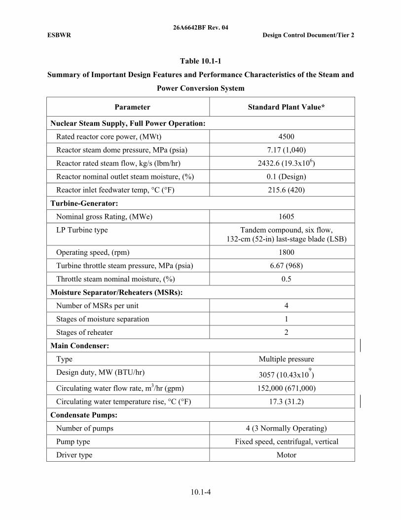
The important steam and power conversion system design parameters are summarized in Table 10.1-1. The principal features are illustrated in Figure 10.1-1.
Normally, the turbine power heat cycle utilizes all the steam being generated by the reactor; however, an automatic pressure-controlled turbine bypass system designed for full load rejection capability is provided to discharge excess steam directly to the condenser.
Individual components of the steam and power conversion system are based on proven conventional designs suitable for use in large, central station power plants.
Auxiliary equipment is designed to support the maximum calculated unit capability.
Table 10.1-1 shows the ESBWR standard plant steam and power conversion system heat input available from the Nuclear Steam Supply System (NSSS) when the reactor core is generating its rated output. The steam and power conversion system is designed with the capability to operate at approximately 105% of rated turbine throttle flow (assumed to correspond to turbine valves wide open).
26A6642BF Rev. 04 ESBWR Design Control Document/Tier 2
10.1-2
The inlet pressure at the turbine main steam valves reflects reactor power, steam line flow and pressure regulator programming but never exceeds the pressure for which the turbine components and steam lines are designed.
The necessary biological shielding for personnel protection is provided for all required radiation producing components of the steam and power conversion system including the main turbines, MSRs, feedwater heaters, condenser and steam jet air ejectors.
The approximate rated and valves-wide open flow quantities and fluid pressures and temperatures are shown on the turbine cycle heat balances, Figures 10.1-2 and 10.1-3, respectively. These represent the ESBWR standard plant cycle; actual values can vary.
The No. 7 feedwater heaters are not shown on the heat balance figures. These heaters are only used for off-rated operation during power maneuvering and are not considered in the plant heat rate performance. Reference Subsection 10.4.7.2.2.3 for a description of the No. 7 feedwater heaters.
The majority of the steam and power conversion system is located in the Turbine Building.
Nonsafety-related instrumentation is provided to measure flow, pressure, differential pressure, temperature, and level at selected locations in the Turbine Main Steam System (TMSS) and Condensate and Feedwater System (C&FS). The instrumentation provides input signals to the Nonsafety-related Distributed Control Information System (N-DCIS) that monitors and controls the normal operation of the plant.
Safety-related instrumentation is provided to measure the main condenser (shell) pressure, main turbine stop valve positions, hydraulic pressure of the turbine control valves, and the bypass valve positions. A safety-related instrument is also provided to monitor the power generation electrical bus for an undervoltage condition, indicating a loss of feedwater. These signals go to each division of the Reactor Protection System (RPS). See Subsection 7.2.1 for a description of the RPS interface for these devices. In addition, there is safety-related instrumentation provided to measure main steam header (turbine inlet) pressure and instruments to provide indication of main steam line leakage. These signals go to each division of the Leak Detection and Isolation System (LD&IS). See Subsection 7.3.3 for a description of the LD&IS.
10.1.1 Protective Features
10.1.1.1 Loss of External Electrical Load and/or Turbine Trip
Load rejection capabilities of the steam and power conversion systems are discussed in Subsection 10.4.4.
10.1.1.2 Overpressure Protection
The following components are provided with overpressure protection in accordance with the American Society of Mechanical Engineers (ASME) Boiler and Pressure Vessel Code, Section VIII:
• Moisture separator/reheater vessels and drain tanks,
• Selected low pressure feedwater heaters,

26A6642BF Rev. 04 ESBWR Design Control Document/Tier 2
10.1-3
• High pressure feedwater heaters, and
• Open feedwater heater storage tank.
10.1.1.2.1 Turbine Overspeed Protection
Turbine overspeed protection is discussed in Subsection 10.2.2.4.
10.1.1.2.2 Turbine Integrity
Turbine integrity is discussed in Subsections 3.5.1 and 10.2.3.
10.1.2 COL Information
None
10.1.3 References None
26A6642BF Rev. 04 ESBWR Design Control Document/Tier 2
10.1-4
Table 10.1-1
Summary of Important Design Features and Performance Characteristics of the Steam and
Power Conversion System
Parameter Standard Plant Value*
Nuclear Steam Supply, Full Power Operation:
Rated reactor core power, (MWt) 4500
Reactor steam dome pressure, MPa (psia) 7.17 (1,040)
Reactor rated steam flow, kg/s (lbm/hr) 2432.6 (19.3x10⁶)
Reactor nominal outlet steam moisture, (%) 0.1 (Design)
Reactor inlet feedwater temp, °C (°F) 215.6 (420)
Turbine-Generator:
Nominal gross Rating, (MWe) 1605
LP Turbine type Tandem compound, six flow, 132-cm (52-in) last-stage blade (LSB)
Operating speed, (rpm) 1800
Turbine throttle steam pressure, MPa (psia) 6.67 (968)
Throttle steam nominal moisture, (%) 0.5
Moisture Separator/Reheaters (MSRs):
Number of MSRs per unit 4
Stages of moisture separation 1
Stages of reheater 2
Main Condenser:
Type Multiple pressure
Design duty, MW (BTU/hr) 3057 (10.43x10⁹)
Circulating water flow rate, m3/hr (gpm) 152,000 (671,000)
Circulating water temperature rise, °C (°F) 17.3 (31.2)
Condensate Pumps:
Number of pumps 4 (3 Normally Operating)
Pump type Fixed speed, centrifugal, vertical
Driver type Motor

26A6642BF Rev. 04 ESBWR Design Control Document/Tier 2
10.1-5
Table 10.1-1
Summary of Important Design Features and Performance Characteristics of the Steam and
Power Conversion System
Parameter Standard Plant Value*
Normal flow, kg/hr (lbm/hr) 5.8x10⁶ (12.8x10⁶)
Feedwater Heaters:
No. 1:
Number per stage 3
Stage pressure, kPa (psia) 55 (8)
No. 2:
Number per stage 3
Stage pressure, kPa (psia) 110 (16)
No. 3:
Number per stage 3
Stage pressure, kPa (psia) 221 (32)
No. 4 (Open type. Feedwater Tank):
Number per stage 1
Stage pressure, kPa (psia) 407 (59)
Net feedwater volume, m3 (ft3) 680 (24x103)
No. 5:
Number per stage 2
Stage pressure, kPa (psia) 1282 (186)
No. 6:
Number per stage 2
Stage pressure, kPa (psia) 2255 (327)
No. 7:
Number per stage (Normally only used for power maneuvering)
2

26A6642BF Rev. 04 ESBWR Design Control Document/Tier 2
10.1-6
Table 10.1-1
Summary of Important Design Features and Performance Characteristics of the Steam and
Power Conversion System
Parameter Standard Plant Value*
Reactor Feedwater Pump:
Number of pumps (booster and main pump) 4 (3 Normally Operating)
Pump type Variable speed, centrifugal, horizontal
Driver type Motor
Design flow, kg/hr (lbm/hr) 8.8x10⁶ (19.3x10⁶)
* Value is shown for rated operation. These are representative values for the ESBWR standard plant cycle; actual values can vary slightly.

26A6642BF Rev. 04 ESBWR Design Control Document/Tier 2
10.1-7
Figure 10.1-1. Power Cycle Schematic

26A6642BF Rev. 04 ESBWR Design Control Document/Tier 2
10.1-8
Figure 10.1-2. Rated Heat Balance

26A6642BF Rev. 04 ESBWR Design Control Document/Tier 2
10.1-9
Figure 10.1-3. Valves Wide Open-Heat Balance

26A6642BF Rev. 04 ESBWR Design Control Document/Tier 2
10.2-1
10.2 TURBINE GENERATOR
10.2.1 Design Bases
The design of the Turbine Generator (TG) system meets the requirement of General Design Criterion 4 as related to the protection of safety-related structures, systems and components from the effects of turbine missiles. It provides a redundant turbine overspeed protection system to minimize the probability of turbine missile generation. In addition, the ESBWR standard plant design has a favorably oriented turbine to minimize any potential impact on safety-related structures and equipment. Favorably oriented turbine generators are located such that the containment and most safety-related Systems, Structures and Components (SSCs) outside containment are excluded from the low-trajectory hazard zone described in RG 1.115.
The required total turbine missile generation probability for loading the turbine and bringing the system online is less than 1x10⁻⁴ per year as outlined in Table 3.5-1. With rotor designs that utilize large integral forgings, the total turbine missile generation probability is reduced. For ESBWR, assuming the recommended inspections and tests are conducted at the recommended frequencies, this value is less than 1x10⁻⁵ per year.
10.2.1.1 Safety (10 CFR 50.2) Design Bases
The TG does not perform or support any safety-related function, and thus, has no safety design basis. The TG is, however, a potential source of high energy missiles that could damage safety-related equipment or structures. The turbine is designed to minimize the possibility of failure of a turbine blade or rotor. Turbine integrity is discussed in Subsection 10.2.3. The effects of potential high energy missiles are discussed in Section 3.5 and Subsection 10.2.4.
10.2.1.2 Non-Safety Power Generation Design Bases
• The TG has base load and load following capability.
• The gross generator outputs at ESBWR standard plant reactor rated thermal power and Valves Wide Open (VWO) operation are given on the heat balances shown on Figures 10.1-2 and 10.1-3, respectively.
• The TG load change characteristics are compatible with the Plant Automation System (PAS), which coordinates TG and reactor operation.
• The TG is designed to accept a sudden loss of full load with sufficient margin to the overspeed trip.
• The TG is designed to permit periodic testing under power operation conditions of steam valves important to overspeed protection and overspeed trip circuits.
• The failure of any single component does not cause the rotor speed to exceed 120% of rated speed.
• Turbine control functions, which are required for turbine protection, possess sufficient redundancy such that failure of a single component input does not disable the turbine protection system.

26A6642BF Rev. 04 ESBWR Design Control Document/Tier 2
10.2-2
• The TG auxiliary systems (stator cooling, lube oil cooling, etc.) are designed either with enough redundancy to support full power operation with a single failure or to provide a signal to the main control room to prompt a reduction in power to within the capability of the remaining auxiliary systems.
10.2.1.3 Functional Limitations Imposed by the Design or Operational Characteristics of the Reactor Coolant System
Turbine main steam stop, control valves, intermediate stop valves, and intercept valves protect the turbine from excessive speeds. The Steam Bypass and Pressure Control System (SB&PC) protects the reactor system from abnormal pressure surges. Operation of the SB&PC System is discussed in Subsection 7.7.5. The valve arrangements and valve closure times are such that a failure of any single valve to operate does not result in the unit exceeding 120% of rated speed or an abnormal pressure surge in the event of a TG trip signal or near full load rejection.
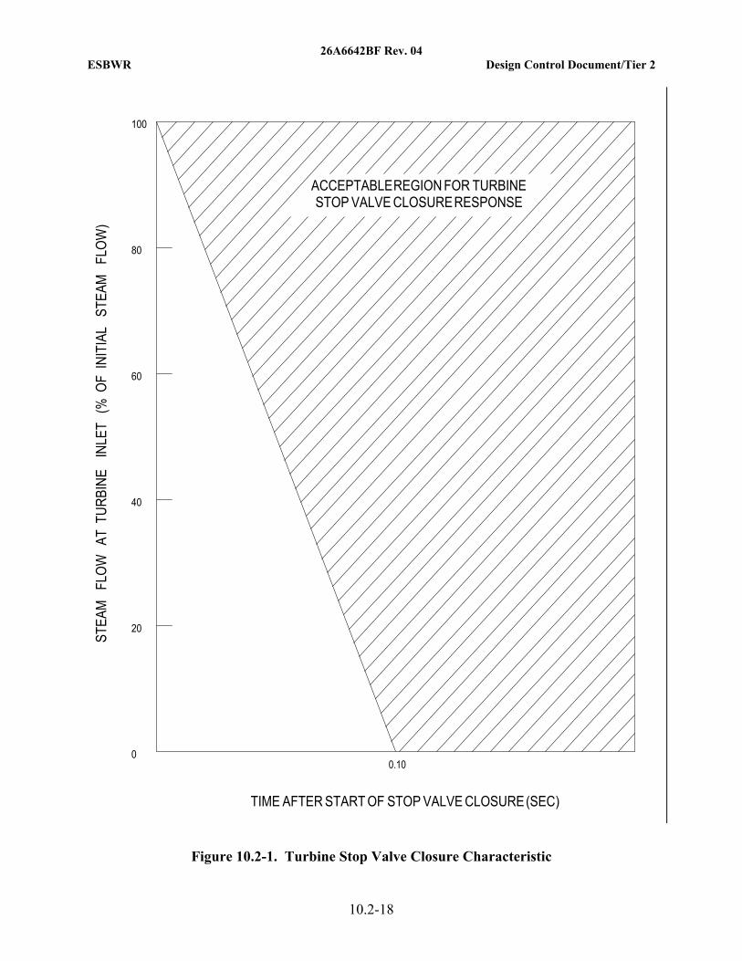
10.2.1.3.1 Turbine Stop Valve
During an event resulting in turbine stop valve fast closure, turbine inlet steam flow is not reduced faster than that shown in Figure 10.2-1.
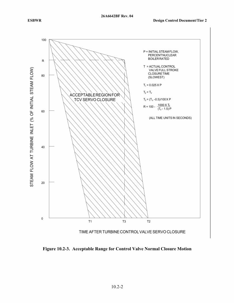
10.2.1.3.2 Turbine Control Valve
During any event resulting in turbine control valve fast closure, the turbine inlet steam flow is not reduced faster than that shown in Figure 10.2-2.
The turbine control valve steam flow shutoff rate, upon a step reduction to zero in pressure regulation flow demand (no resulting bypass steam flow demand), is within the region shown in Figure 10.2-3. Any single control system failure or TG event does not cause a faster steam flow reduction than that shown in Figure 10.2-3 without generating control valve fast closure signals to the RPS.
10.2.1.3.3 Load Maneuvering Capability
The plant is capable of daily load following with control rod drive operation between 100% and 50% of rated power on a 14-1-8-1 hour cycle and with ramp rates up to ±1%/minute.
Power maneuvers within the capabilities above do not require isolation or bypass of condensate/feedwater equipment such as feedwater heaters.
10.2.2 Description
10.2.2.1 General Description
The TG consists of an 1800 rpm turbine, external moisture separator/reheaters, generator, exciter, controls, and associated subsystems.
The turbine for the ESBWR standard plant consists of a double-flow, high pressure unit, and three double flow low pressure units in tandem. The high pressure turbine has extraction points for reheating steam and high pressure feedwater heating.
Moisture separation and reheating of the high pressure turbine exhaust steam is performed by external Moisture Separator Reheaters (MSRs). The MSRs are located on each side of the TG
26A6642BF Rev. 04 ESBWR Design Control Document/Tier 2
10.2-3
centerline. The steam then passes through the low pressure turbines, each with extraction points for the low pressure stages of feedwater heating, and exhausts into the main condenser. In addition to the moisture separators in the external MSRs, the turbine steam path has provisions for removing some additional moisture and routing it to extraction lines.
The generator is a direct driven, three-phase, 60 Hz, 1800 rpm synchronous generator with a water-cooled armature winding and hydrogen-cooled rotor.
The TG uses a digital monitoring and control system, which, in coordination with the turbine SB&PC, controls the turbine speed, load, and flow for startup and normal operations. The control system operates the turbine stop valves, control valves, and intermediate stop and intercept valves. TG supervisory instrumentation is provided for operational analysis and malfunction diagnosis.
TG accessories include the bearing lubrication oil system, Turbine Generator Control System (TGCS), turbine hydraulic system, turning gear, hydrogen gas control system, seal oil system, stator cooling water system, exhaust hood spray system, turbine gland seal system, MSR reheater heating steam system, and turbine supervisory instrument system.
The TG unit and associated high energy piping, valves, and instruments are located completely within the Turbine Building. Any postulated failure associated with the TG unit does not affect any essential systems or components as defined in BTP SPLB 3-1. Failure of TG equipment cannot preclude safe shutdown of the reactor system. TG system components, equipment, and piping are classified as discussed in Section 3.2.
10.2.2.2 Component Description
The MSRs, MSR drain tanks, stator water coolers, and stator water demineralizer are designed to ASME Code Section VIII requirements. The balance of the TG is designed to turbine manufacturer’s standards. All valves important to overspeed protection are designed with closing times sufficient to prevent the turbine from exceeding design overspeed conditions.
10.2.2.2.1 Main Stop and Control Valves
Four main stop and four control valves admit steam to the High Pressure (HP) turbine. The primary function of the main stop valves is to quickly shut off the steam flow to the turbine under trip conditions. The primary function of the control valves is to control steam flow to the turbine in response to the TGCS.
The main stop valves are hydraulically operated in an open-closed mode either by the turbine overspeed protection system in response to a turbine trip signal, or by a test solenoid valve and a fast acting solenoid valve for periodic testing. The disks are unbalanced and cannot open against full differential pressure. A bypass is provided to pressurize the below seat areas of the four valves and supply steam for turbine casing and steam chest warming. Springs in the valves are designed to improve the closing time response of the main stop valve under the abnormal conditions listed in Subsection 10.2.2.5. An equalizing header is provided between the stop valves, upstream of the control valves.
Each main stop valve is designed to accept a steam strainer to limit foreign material from entering the control valves and turbine.

26A6642BF Rev. 04 ESBWR Design Control Document/Tier 2
10.2-4
The control valves are designed to provide steam shutoff adequate for turbine speed control. The valves are of sufficient size, relative to their cracking pressure, to require a partial balancing. Each control valve is hydraulically operated by a servomotor opened by a high pressure fire-resistant fluid supplied through a servo valve.
10.2.2.2.2 High Pressure Turbine
The HP turbine receives steam through four steam leads, one from each control valve outlet. The steam is expanded axially across several stages of stationary and moving blades. Extraction steam from the HP turbine supplies the sixth stage of feedwater heating and first stage reheaters. HP turbine exhaust steam is collected in eight cold reheat pipes, four at each end of the HP casing, and is routed to the inlets of the MSRs.
10.2.2.2.3 Moisture Separator Reheaters
Horizontal, cylindrical-shell, combined MSRs are installed in the steam path between the high and low pressure turbines. The MSRs serve to dry and reheat the HP turbine steam exhaust (cross around steam) before it enters the low pressure turbines. This improves cycle efficiency and reduces liquid impingement erosion (LIE) and flow-accelerated corrosion (FAC) in the low pressure turbines. Cold reheat steam is piped into the bottom of the MSRs. Moisture is removed in chevron-type moisture separators, and is drained to the appropriate stage of feedwater heating. The steam next passes upward across the two reheater stages. Heating steam to the first reheater stage is supplied by extraction steam and heating steam to the second reheater stage is supplied with main steam. Reheated steam is routed to the intermediate stop and intercept valves, which are located just upstream of the low pressure turbine inlet nozzles. Safety relief valves are provided on the MSRs for overpressure protection.
10.2.2.2.4 Intermediate Stop and Intercept Valves
Hydraulically operated intermediate stop and intercept valves are provided in each hot reheat line just upstream of the Low Pressure (LP) turbine inlet.
Upon loss of load, the intercept valves first close then throttle steam to the LP turbine as required to control speed. The intermediate stop valves close on a turbine trip. The intermediate stop and intercept valves are designed to close rapidly to control turbine overspeed.
10.2.2.2.5 Low Pressure Turbines
Each LP turbine receives steam from the MSRs through two hot reheat lines. The steam expands axially across several stages of stationary and moving blades.
Extraction steam from the LP turbines supplies the first stages of feedwater heating.
10.2.2.2.6 Extraction Non-return Valves Upon loss of load, the steam contained downstream of the turbine extractions can flow back into the turbine, across the remaining turbine stages, and into the condenser. Associated condensate can flash to steam under this condition and contribute to the backflow of steam or can be entrained with the steam flow and damage the turbines. Non-return valves are employed in selected extraction lines to minimize potential for overspeeding and also for preventing water entrainment (see Subsection 10.2.2.4).

26A6642BF Rev. 04 ESBWR Design Control Document/Tier 2
10.2-5
10.2.2.2.7 Generator
The generator is a direct-driven, three-phase, 60 Hz, 1800 rpm, four-pole synchronous generator with a water-cooled armature winding and hydrogen-cooled rotor.
The rotor is manufactured from forged components and includes layers of field windings embedded in milled slots. The windings are held radially by slot wedges, at the rotor outside diameter. The wedge material maintains its mechanical properties at elevated temperature. The magnetic field is generated by direct current (DC) power, which is fed to the windings through collector rings located outboard of the main generator bearings.
The rotor body and shaft is machined from a single, solid steel forging. Detailed examinations include:
• Material property checks on test specimens taken from the forging,
• Photomicrographs for examination of microstructure,
• Magnetic particle and ultrasonic examination, and
• Visual surface finish inspections of rotor slots for indication of a stress riser.
10.2.2.2.8 Hydrogen Gas Control System
The Hydrogen Gas Control System (HGCS) is illustrated on Figure 10.2-4. The HGCS is designed to provide the necessary flow and pressure at the main generator for purging carbon dioxide during startup and supply makeup hydrogen for generator leakage during normal operation.
The HGCS consists of hydrogen supply piping with all the necessary valves, instrumentation, gas purity measuring equipment, hydrogen gas dryers, and bulk hydrogen storage unit.
Fires and explosions during filling and/or purging of the generator are prevented by inerting the generator with CO2 so that a flammable mixture of hydrogen and oxygen cannot be produced. Unneeded hydrogen is vented outside through a flame arrestor.
The bulk hydrogen system utilizes the guidelines given in Reference 10.2-2. Specifically, the bulk hydrogen system piping and components are located to reduce risk from their failures. The bulk hydrogen storage is located outside the Turbine Building at a distance great enough to ensure no structural damage from a hydrogen detonation. The hydrogen lines are provided with a pressure reducing station that limits the maximum flow before entering the Turbine Building. Equipment and controls are designed to be accessible and remain functional after a bulk hydrogen storage detonation. The design features and/or administrative controls are provided to ensure that the hydrogen supply is isolated when normal building ventilation is lost.
The arrangement of buildings at the facility and the location of building doors and bulk hydrogen storage tanks ensure that damage to buildings containing safety-related equipment due to detonation or combustion of hydrogen is unlikely.
Additionally, the bulk hydrogen system piping in the Turbine Building is designed in accordance with industry practice and applicable codes and standards.

26A6642BF Rev. 04 ESBWR Design Control Document/Tier 2
10.2-6
10.2.2.3 Normal Operation
During normal operation, the main stop valves, intermediate stop valves, and intercept valves are wide open. Operation of the TG is under the control of the TGCS. The SB&PC System controls the turbine control valves through the TGCS to regulate reactor pressure. The normal function of the TGCS is to generate the position signals for the main stop valves, main control valves, intermediate stop valves, and intercept valves.
10.2.2.4 Turbine Overspeed Protection System
The normal speed control system comprises the first line of defense against turbine overspeed. This system includes the main control valves, intercept valves, and fast-acting valve-closing functions within the TGCS. The normal speed control unit utilizes three speed signals. Loss of any two of these speed signals initiates a turbine trip via the Emergency Trip System (ETS). An increase in speed above setpoint tends to close the control and intercept valves in proportion to the speed increase. Rapid turbine acceleration resulting from a sudden loss of load at higher power levels normally initiates the fast-acting solenoids via the normal speed control system. The fast-acting solenoids rapidly close the main control and intercept valves irrespective of the current turbine speed.
The normal speed control system is designed to limit peak overspeed resulting from a loss of full load, to at least 1% below the overspeed trip set point. Typically, this peak speed is in a range of 106-109% of rated speed, and the overspeed trip set point is typically close to 110% of rated speed. All turbine steam control and intercept valves are fully testable during normal operation. The fast closing feature, provided by action of the fast-acting solenoids, is testable during normal operation.
Normal speed control is supplemented by the Power Load Unbalance (PLU) function. The PLU function can protect the turbine from an overspeed trip condition in the event of full load rejection. The PLU function looks for an unbalance between mechanical power and electrical load. Under specific load rejection conditions, the PLU will initiate main control valve and intercept valve fast closing functions to prevent rapid acceleration and a subsequent turbine trip.
If the normal speed control and PLU function should fail, the overspeed trip devices close the main and intermediate stop valves. This turbine overspeed protection system comprises the second line of defense against turbine overspeed. It is both redundant and diverse.
Redundancy comes from the use of multiple speed probes, multiple controllers, and multiple trip solenoid valves. The turbine hydraulic trip solenoid valve hydraulic circuits are arranged in a dual, “two-out-of-three,” de-energize to trip configuration. Any power interruption to either set of the two-out-of-three trip solenoid valves in the Emergency Trip Device (ETD) results in a turbine trip.
Diversity is provided by separate sets of physically isolated primary and emergency overspeed protection controllers. The primary overspeed trip and emergency overspeed trip controllers are independent and diverse by providing unique hardware and logic design and implementation. Power to the trip solenoids is interrupted by either the primary overspeed protection controllers or by the emergency overspeed protection controllers. An overspeed trip results if either set of redundant controllers determines an overspeed condition exists. Power interruption to the turbine control cabinet (which also supplies power to the trip solenoids) results in a “fail-safe”

26A6642BF Rev. 04 ESBWR Design Control Document/Tier 2
10.2-7
turbine trip. The trip solenoid valve and associated controller are fully testable during normal operation.
For an actual overspeed trip condition, the primary overspeed controllers exchange and vote their individual speed inputs so each controller executes its protective algorithm on the consensus speed value. Each primary overspeed controller de-energizes trip solenoid valves in a two-out-of-three logic arrangement. The two-out-of-three logic precludes a single failure in any of the three controllers from blocking trip initiation.
A different implementation and operation takes place in the three completely separate and individual emergency overspeed trip controllers. Each of the three emergency controllers has a dedicated power supply and operates completely separate from each of the other emergency overspeed trip controllers. The three emergency controllers operate independently from the primary overspeed trip controllers. In the event of an overspeed condition, the emergency controllers individually detect and determine speed, and de-energize trip solenoid valves in a two-out-of-three logic arrangement.
The overspeed protection system is designed to ensure that failure of the normal speed control system does not result in turbine speed exceeding 120% of rated speed. The components and circuits comprising the turbine overspeed protection system are testable when the turbine is in operation.
The overspeed sensing devices are located in the turbine front bearing standard, and are therefore protected from the effects of missiles or pipe breakage. The hydraulic lines are fail-safe; if one is broken, loss of hydraulic pressure results in a turbine trip. The ETD is also fail-safe. Each trip solenoid transfers to the trip state on a loss of control power, resulting in a turbine trip. These features provide inherent protection against failure of the overspeed protection system caused by low trajectory missiles or postulated piping failures.
Each turbine extraction line is reviewed for potential energy and contribution to overspeed. The number and type of extraction non-return valves required for each extraction line are specified based on the enthalpy and mass of steam and water in the extraction line and feedwater heater. Higher energy lines are provided with power-assisted open, spring-assisted closed non-return valves, controlled by air relay dump valves, which in turn, are activated by the emergency trip fluid system. The air relay dump valves, actuated on a turbine trip, dump air from the extraction non-return valve actuators to provide rapid closing via actuator spring force. The closing time of the extraction non-return valves is sufficient to minimize extraction steam contribution to the turbine overspeed event.
The following component redundancies are employed to guard against excessive overspeed:
(1) Main stop valves/Control valves
(2) Intermediate stop valves/Intercept valves
(3) Normal speed control/Primary overspeed trip/Emergency overspeed trip
(4) Fast-acting solenoid valves/Emergency trip fluid system (ETD)
The main stop valves and control valves provide full redundancy in that these valves are in series and have independent control signals and operating mechanisms. Closure of all four stop valves or all four control valves shuts off all main steam flow to the HP turbine. The intermediate stop

26A6642BF Rev. 04 ESBWR Design Control Document/Tier 2
10.2-8
and intercept valves are also in series and have independent control signals and operating mechanisms. Closure of either valve or both valves in each of the six sets of intermediate stop and intercept valves effectively shuts off intermediate steam flow to the three LP turbines. This arrangement is such that failure of a single valve to close does not result in turbine speed exceeding 120% of rated speed.
10.2.2.5 Turbine Protection System
In addition to the overspeed trip signals discussed, the ETS closes the main stop and control valves and the intermediate stop and intercept valves to shut down the turbine on the following signals.
• Emergency trip in control room,
• Moisture Separator high level,
• High condenser pressure,
• Low lube oil pressure,
• LP turbine exhaust hood high temperature,
• High reactor water level,
• Thrust bearing wear,
• Emergency trip at front standard,
• Loss of stator coolant (if runback fails),
• Low hydraulic fluid pressure,
• Selected generator trips,
• Loss of TGCS electrical power,
• Excessive turbine shaft vibration,
• Loss of two speed signals – either Normal Speed Control or Emergency,
• Loss of two or more Steam Bypass and Pressure Control System (SB&PC) channels, and
• Closure of two or more MSIVs.
When the ETS is activated, it overrides all operating signals and trips (closes) the main stop and control valves, and intermediate stop and intercept valves.
10.2.2.6 Turbine Generator Supervisory Instruments
Although the turbine is not readily accessible during operation, the Turbine Supervisory Instrumentation (TSI) is sufficient to detect specific turbine generator malfunctions. The TSI includes monitoring of the following:
• Vibration and eccentricity;
• Thrust bearing wear;
• Exhaust hood temperature;

26A6642BF Rev. 04 ESBWR Design Control Document/Tier 2
10.2-9
• Oil system pressures, levels and temperatures;
• Bearing metal and oil drain temperatures;
• Shell temperature;
• Valve positions;
• Shell and rotor differential expansion;
• Shaft speed, electrical load, and control valve inlet pressure indication;
• Hydrogen temperature, pressure and purity;
• Stator coolant temperature and conductivity;
• Stator-winding temperature;
• Exciter temperatures;
• Turbine gland sealing pressure;
• Gland steam condenser vacuum;
• Steam chest pressure; and
• Seal oil pressure.
10.2.2.7 Testing
The Primary and Emergency overspeed trip circuits and devices are tested remotely at or above rated speed by means of controls in the Main Control Room (MCR). Operation of the overspeed protection devices under controlled speed conditions is checked at startup and after each refueling or major maintenance outage. In some cases, operation of the overspeed protection devices can be tested just prior to shutdown. This eliminates the need to test overspeed protection devices during the subsequent startup if no maintenance is performed that affects the overspeed trip circuits and devices.
During refueling, or maintenance shutdowns, coinciding with the in-service inspection schedule required by Section XI of the ASME Code for reactor components, at intervals defined in Subsection 10.2.3.7, at least one main stop valve, one main control valve, one intermediate stop valve, and one intercept valve are dismantled to conduct visual and surface examinations of valve seats, disks, and stems. If unacceptable flaws or excessive corrosion is found in a valve, all other valves of that type should be dismantled and inspected. Valve bushings are inspected and cleaned, and bore diameters checked for proper clearance.
Main stop, main control, intermediate stop, and intercept valves are exercised at least once within each calendar quarter (or as required by the turbine missile probability analysis) by closing each valve and observing the remote valve position indicator for fully CLOSED position status. This test also verifies operation of the fast close function of each main stop and main control valve during the last few percent of valve stem travel. Fast closure of the intermediate stop and intercept valves is tested in a similar way if they are required to have a fast close function that is different from the test exercise.

26A6642BF Rev. 04 ESBWR Design Control Document/Tier 2
10.2-10
Access to required areas outside of the turbine shielding is provided on the turbine floor under operating conditions.
Provisions are included for testing each of the following devices while the unit is operating:
• Main stop valves and main control valves,
• Low pressure turbine intermediate stop and intercept valves,
• Turbine Extraction non-return valves,
• Lubricating oil pumps,
• Hydraulic fluid pumps,
• Emergency Trip Device, and
• Power-Load Unbalance circuits.
10.2.3 Turbine Integrity
10.2.3.1 Materials Selection
Turbine rotors are made from vacuum treated or remelted alloy steel components using processes that minimize flaw occurrence, assure uniform strength, and provide adequate fracture toughness. Undesirable elements, such as sulfur and phosphorus, are controlled to the lowest practical concentrations consistent with good scrap selection and melting practice, and consistent with obtaining adequate initial and long-life fracture toughness for the environment in which the parts operate. The turbine materials have the lowest Fracture Appearance Transition Temperatures (FATT) and highest Charpy V-notch (Cv) energies obtainable, on a consistent basis from material at the sizes and strength levels used.
10.2.3.1.1 Materials for Turbine Disc Forgings
Low pressure turbine wheel (disc) forgings are made from vacuum treated Ni-Cr-Mo-V alloy steel forgings. The fracture appearance transition temperature (50% FATT), as obtained from Charpy tests performed in accordance with American Society of Testing Methods (ASTM) A-370, is no higher than 0ºF for low pressure turbine wheel (disc) forgings. The Cv energy at the minimum operating temperature is at least 60 ft-lbs for a low pressure turbine wheel (disc) forging. A minimum of three Cv specimens are tested in accordance with specification ASTM A-370 to determine this energy level. The determination of FATT is used in lieu of nil-ductility transition temperature methods.
10.2.3.1.2 Materials for Integral Rotor Forgings
Large integral rotors are made from vacuum treated Ni-Cr-Mo-V alloy steel forgings. Their larger size limits the achievable properties. The fracture appearance transition temperature (50% FATT), as obtained from Charpy tests performed in accordance with ASTM A-370, is no higher than +30ºF for large integral forgings. The Cv energy at the minimum operating temperature is at least 45 ft-lbs for a large integral rotor forging. A minimum of three Cv specimens is tested in accordance with specification ASTM A-370 to determine this energy level.

26A6642BF Rev. 04 ESBWR Design Control Document/Tier 2
10.2-11
Current turbine designs utilize rotors produced from large integral forgings. Future turbine designs may include fabricated rotors produced from multiple wrought components. Acceptable material properties will be consistent with component size and fabrication method.
10.2.3.2 Fracture Toughness
Suitable material toughness is obtained through the use of selected materials as described in Subsection 10.2.3.1, to produce a balance of material strength and toughness to ensure safety while simultaneously providing high reliability, availability, and efficiency during operation.
Stress calculations include consideration of centrifugal loads, interference fit, and thermal gradients where applicable. The ratio of material fracture toughness, K1c (as derived from material tests on each major part or rotor), to the maximum tangential stress intensity at speeds from normal to design overspeed, is at least two at minimum operating temperature. Adequate material fracture toughness needed to maintain this ratio is assured by a large historical database of tests. When required, sufficient warm-up time or other procedures are specified in the turbine operating instructions to ensure that the above ratio of fracture toughness to stress intensity is maintained during all phases of anticipated turbine operation.
10.2.3.3 High Temperature Properties
The operating temperature range of both the high pressure and low pressure rotors is below the stress rupture temperature range of the materials used. Therefore, creep-rupture is not considered to be a significant failure mechanism for these components.
10.2.3.4 Turbine Design
The turbine for the ESBWR standard plant employs integral forgings for the rotors. The integral forging rotor design yields a number of benefits compared to earlier designs with shrunk-on disks. For example, the integral forging rotor is inherently less likely to have a failure resulting in a turbine missile than previous designs with shrunk-on disks and keyways. By eliminating disk bores and keyways, many of the associated stress risers and areas where contaminants collect and concentrate have been eliminated. This design feature minimizes the occurrence of stress corrosion cracking.
The turbine blades are also designed to improve safety and reliability. Some blades in high stress regions utilize axial entry dovetails. This feature allows the designer to optimize the allocation of stress between the blade and rotor dovetail, taking into account the relative strengths of the two materials. Certain blades also incorporate the use of integral covers and mid-span wings. The contact surfaces provided by these features act as frictional dampeners that dissipate vibration energy and reduce the maximum amplitude of vibration. These features also couple the blades into a single structure, raising the natural frequency, thereby reducing the response to flow induced vibration. The end result achieved by incorporation of the above blade design features is decreased vibration and fatigue and enhanced reliability.
The turbine assembly is designed to maintain structural integrity during normal and upset operating conditions including anticipated operational occurrences and accidents resulting in a turbine trip. The design of the turbine assembly meets the following criteria:

26A6642BF Rev. 04 ESBWR Design Control Document/Tier 2
10.2-12
• Turbine shaft bearings and pedestals are designed to retain their structural integrity when subjected to any combination of loads from normal and upset operating conditions, anticipated operational occurrences, and accidents resulting in turbine trips.
• The natural lateral critical frequencies of the turbine shaft assemblies existing between zero speed and 120% overspeed are controlled in the design and operation so as to cause no distress to the unit during operation. A torsional vibration analysis shows that the TG rotor resonance is outside of the normal operating frequency and its harmonics.
• The turbine rotor average tangential stress (excluding stresses in the blade/wheel region) at design overspeed resulting from centrifugal forces, interference fit (as applicable), and thermal gradients does not exceed 0.75 of the minimum specified yield strength of the material.
• The overspeed trip set point of the turbine is approximately 110% (of rated speed). This overspeed trip set point is at least 1% above the highest anticipated speed resulting from loss of load, which is normally in the range of 106-109%. The turbine assembly is designed and tested to withstand the stresses corresponding to an overspeed level of 120%. This speed is approximately 10% above the highest anticipated speed resulting from loss of load. The final overspeed basis and setpoints are included with the turbine missile probability analysis (see Subsection 10.2.3.8).
• Integral forging rotor designs are employed to eliminate adverse effects such as fretting and loosening of discs that are associated with designs that utilize shrunk-on discs.
• Nuclear Boiler System (NBS) chemistry and thus Turbine Main Steam System (TMSS) chemistry are carefully controlled to minimize the potential effects of pitting and stress corrosion cracking of turbine rotors and blades. Expected ESBWR water quality parameters are provided in Table 5.2-5. The expected reactor water quality exceeds the turbine manufacturer’s requirements for steam and condensate purity.
• The turbines are built with moisture control features and drain points that remove excessive moisture from the turbine steam path. This design feature, combined with moisture separation and reheat capability provided by the external Moisture Separator Reheaters (MSRs), limits the effects of moisture-related erosion damage to the turbine blades, casings, and rotors. Collected moisture is discharged via extraction point connections to feedwater heaters or through drains to the condenser.
• The turbine missile probability analysis discussed in Subsection 10.2.3.8 contains additional description of the design features of the turbine, rotor, shaft, couplings, and blades, including the number of stages, blade design, how the blades are attached to the rotor, how the turbine rotor is forged, and pertinent fabrication methods. Informational drawings are included as required to illustrate important design features.
• The turbine missile probability analysis discussed in Subsection 10.2.3.8 includes an analysis of turbine component loading. The analysis includes rotor and blade loading combinations. The analysis shows that the rotor and blades have adequate margin to withstand loadings imposed during postulated overspeed events up to 120% of rated speed without detrimental effects.

26A6642BF Rev. 04 ESBWR Design Control Document/Tier 2
10.2-13
10.2.3.5 Preservice Inspection
The preservice inspection procedures and acceptance criteria are as follows:
• Forgings are rough-machined with minimum stock allowance prior to heat treatment.
• Forgings undergo 100% volumetric (ultrasonic), visual, and surface examinations subject to established inspection methods and acceptance criteria that are equivalent to or more restrictive than those specified for Class 1 components in ASME Code Sections III and V. Subsurface sonic indications are not accepted if found to compromise the integrity of the unit during its service life. Rotor forgings may be bored to remove defects, obtain material for testing and to conduct bore sonic inspection.
• All steam path surfaces are surface examined before any welding and/or brazing to the finished rotor forging. After welding and/or brazing activities are completed, all steam path surfaces are re-examined with particular attention given to stress risers and welds.
• Specific portions of finish machined rotors, including any bores, keyways, or drilled holes, are subject to magnetic particle test or liquid penetrant examination. Surface indications are evaluated and removed if found to compromise the integrity of the unit during its service life. All flaw indications in keyways and drilled holes are removed.
• Each fully bladed turbine rotor assembly is factory spin-tested at 120% of rated speed.
Additional preservice inspections include air leakage tests performed to determine that the hydrogen cooling system leakage is within the manufacturer’s limits before hydrogen is introduced into the generator casing. The hydrogen purity is tested in the generator after hydrogen has been introduced. The generator windings and required motors are megger-tested. Vibration tests are performed on required motor-driven equipment. Hydrostatic tests are performed on required coolers. Required piping is pressure-tested for leaks. Turbine protection system circuits and hydraulic systems are tested for proper function prior to initial unit startup. The above testing is performed to demonstrate that the TG and related auxiliary systems are available to support power operation.
10.2.3.6 Inservice Maintenance and Inspection of Turbine Rotors
The inservice maintenance and inspection program for the turbine assembly includes the complete inspection of all normally inaccessible parts such as couplings, coupling bolts, turbine shafts, turbine blades and low and high pressure turbine rotors. During plant shutdown (coinciding with the in-service inspection schedule for ASME Section III components, as required by the ASME Boiler and Pressure Vessel Code Section XI), the turbine maintenance and inspection plan is performed in sections during the refueling outages so that a total inspection and any required maintenance have been completed at least once within the time period recommended by the manufacturer. The purpose of the inservice maintenance and inspection plan is to detect flaws that could lead to a failure of the rotor assembly or blades at speeds up to 120% of rated speed.
The recommended maintenance and inspection program plan for the turbine assembly, valves and controls ensures that the annual TG missile probabilities are maintained at or below the acceptable level (see Subsection 10.2.1).
26A6642BF Rev. 04 ESBWR Design Control Document/Tier 2
10.2-14
This inspection consists of visual, surface and volumetric examinations as indicated below.
• Visual, magnetic particle, and ultrasonic examination of all accessible surfaces of rotors.
• Visual and magnetic particle or liquid penetrant examination of all turbine blades.
• Visual and magnetic particle examination of couplings and coupling bolts.
10.2.3.7 Inservice Inspection of Turbine Valves
All main stop valves, control valves, extraction non-return valves, intermediate stop, and intercept valves are tested under load. Test controls installed in the MCR permit full stroking of the stop valves, control valves, and intermediate stop and intercept valves. Valve position indication is provided in the MCR. Some load reduction may be necessary before testing main stop and control valves, intermediate stop and intercept valves.
Main stop, main control, intermediate stop, and intercept valves are exercised at least once within each calendar quarter (or as required by the turbine missile probability analysis) by closing each valve and observing the remote valve position indicator for fully CLOSED position status. This test also verifies operation of the fast closure function of each main stop and main control valve during the last few percent of valve stem travel. Fast closure of the intermediate stop and intercept valves is tested in a similar way if they are required to have a fast close function that is different from the test exercise.
A tightness test of the main stop and main control valves may be performed as required. A tightness test is normally performed by checking the coast down characteristics of the turbine from no load with each set of four main stop and main control valves closed alternately. As alternative methods, warm up steam may be used as an indicator or the turbine speed may be monitored when on the turning gear while opening each set of four main stop and main control valves alternately.
All main stop valves, main control valves, and intermediate stop and intercept valves are disassembled and visually inspected once during the first three refueling shutdowns. Subsequent inspections are scheduled as required to support the turbine missile probability analysis and are consistent with applicable industry practice. The inspections are conducted for:
• Wear of linkages and valve stem packing;
• Erosion of valve seats and stems;
• Deposits on stems and other valve parts, which could interfere with valve operation; and
• Distortions, misalignment or cracks.
Inspection of all valves of one functional type (i.e., stop, control, intercept) should be conducted for any detrimental unusual condition (as defined by the turbine valve in-service inspection program) if one is discovered during the inspection of any single valve.
10.2.3.8 Turbine Missile Probability Analysis
An analysis is prepared containing an evaluation of the probability of turbine missile generation. The report provides a calculation of the probability of turbine missile generation using approved methods and industry guidance applicable to the fabrication technology employed. The analysis

26A6642BF Rev. 04 ESBWR Design Control Document/Tier 2
10.2-15
is a comprehensive report containing a description of turbine fabrication methods, material quality and properties, and required maintenance and inspections.
The following information is contained in the above analysis report:
• The calculated probability of turbine missile generation from material and overspeed related failures based on as-built rotor and blade designs and as-built material properties (as determined in certified testing and Nondestructive Examination (NDE));
• Maximum anticipated speed resulting from a loss of load, assuming normal control system function without trip;
• Overspeed basis and overspeed protection trip setpoints;
• Description of the minimum required inservice inspection and testing program for valves essential to overspeed protection;
• Discussion of the design and structural integrity of turbine rotors (see Subsection 10.2.3.4);
• An analysis of potential degradation mechanisms and any specific maintenance or operating requirements necessary to mitigate the effects of such mechanisms, including pitting, low-cycle fatigue, stress corrosion cracking, corrosion fatigue, erosion and erosion-corrosion;
• List of material properties, including the method of obtaining those properties, that includes yield strength, stress-rupture properties, fracture toughness, and minimum operating temperature of the HP rotor;
• Additional description of pre-service test and inspection procedures and acceptance criteria required to support calculated turbine missile probability;
• Actual maximum tangential and radial stresses and their locations in the LP rotor (see Subsection 10.2.3.4);
• Rotor and blade design analyses, including loading combinations, assumptions and warm-up time, that demonstrate sufficient safety margin to withstand loadings from postulated overspeed events up to 120% of rated speed; and
• A description of inservice tests, inspections, and maintenance activities for the turbine and valve assemblies that are required to support the calculated missile probability, including inspection and test frequencies with technical bases, type of inspection, techniques, areas to be inspected, acceptance criteria, disposition of reportable indications, and corrective actions.
The above analysis/report is prepared using criteria in accordance with NRC requirements that include Reference 10.2-3 and NUREG-0933 item A37 (see Subsection 10.2.5).
The COL Holder will provide an evaluation of the probability of turbine missile generation using the criteria in accordance with NRC requirements (COL 10.2-1-H).

26A6642BF Rev. 04 ESBWR Design Control Document/Tier 2
10.2-16
10.2.4 Evaluation
The turbine generator is nonsafety-related, and is not needed to effect or support a safe shutdown of the reactor.
The turbine is designed, constructed, and inspected to minimize the possibility of any major component failure.
The turbine has a redundant, diverse, and testable overspeed trip system to minimize the possibility of a turbine overspeed event.
The uncontrolled release of stored energy in the extraction steam system is reduced to an acceptable minimum by the addition of non-return valves in selected extraction lines (see Subsection 10.2.2.2.6).
The TG equipment shielding requirements and the methods of access control for required areas of the Turbine Building ensure that the dose criteria specified in 10 CFR 20 for operating personnel are not exceeded. All areas in proximity to TG equipment are zoned according to expected occupancy times and radiation levels anticipated under normal operating conditions. Specification of the various radiation zones in accordance with expected occupancy is listed in Chapter 12. If deemed necessary during unusual occurrences, the occupancy times for certain areas are reduced by administrative controls enacted by health physics personnel.
The design basis operating concentrations of N16 in the turbine cycle are indicated in Section 12.2.
The connection between the low pressure turbine exhaust hood and the condenser is made by means of a steel weld or rubber or stainless steel expansion joint. Because there are no essential systems or components (as defined in BTP SPLB 3-1), in the turbine area, and the condenser is at sub-atmospheric pressure during all modes of turbine operation, failure of the joint has no adverse effects on safety-related equipment.
The TG trip logic and control schemes use coincident logic and redundant controllers and input signals to support the plant availability goals and avoid spurious trips.
All safety-related Systems, Structures and Components (SSCs) outside containment are excluded from the low-trajectory turbine missile strike zone, as defined in RG 1.115, except:
• Four condenser pressure transmitters,
• Four position limit switches per turbine bypass valve, and
• Cabling and connections to the RPS.
The safety-related equipment listed above is potentially within the low-trajectory turbine missile strike zone and subject to direct and indirect effects from turbine missiles. The safety-related condenser pressure transmitters and turbine bypass valve limit switches are part of the safety-related RPS and are therefore classified as safety-related. However, equipment within the RPS is designed to fail into a trip-initiating state on loss of power, loss or disconnection of any input signal, or loss of any internal or external device-to-device connection signal (see Subsection 7.2.1.2.4). Accordingly, damage to the safety-related condenser pressure transmitters and turbine bypass valve limit switches and any associated cabling and connections as the result

26A6642BF Rev. 04 ESBWR Design Control Document/Tier 2
10.2-17
of low-trajectory turbine missiles does not inhibit the safety-related function of the RPS. Therefore, turbine missile protection is not relevant to these affected safety-related SSCs.
10.2.5 COL Information
10.2-1-H Turbine Missile Probability Analysis
The COL Holder will provide an evaluation of the probability of turbine missile generation using the criteria in accordance with NRC requirements (Subsection 10.2.3.8).
10.2.6 References
10.2-1 J. A. Begley and W.A. Logsdon, Westinghouse Scientific Paper 71-1E7 MSLRF-P1.
10.2-2 Electric Power Research Institute, “Guidelines for Permanent BWR Hydrogen Water Chemistry Installations – 1987,” Electric Power Research Institute (EPRI) NP-5283-SR-A, September 1987.
10.2-3 USNRC, “Safety Evaluation Report Relating to the Operation of Hope Creek Generating Station”, NUREG-1048, Supplement No. 6, July 1986.
26A6642BF Rev. 04 ESBWR Design Control Document/Tier 2
10.2-18
100
80
60
40
20
0
ACCEPTABLE REGION FOR TURBINESTOP VALVE CLOSURE RESPONSE
0.10
TIME AFTER START OF STOP VALVE CLOSURE (SEC)
STEA
M
FLOW
AT
TURB
INE
INLE
T (%
OF
INIT
IAL
STEA
M
FLOW
)
Figure 10.2-1. Turbine Stop Valve Closure Characteristic

26A6642BF Rev. 04 ESBWR Design Control Document/Tier 2
10.2-1
Figure 10.2-2. Turbine Control Valve Fast Closure Characteristic
100
80
60
40
20
0
ACCEPTABLE REGION FOR TURBINECONTROL VALVE FAST CLOSURE RESPONSE
T
TIME AFTER START OF CONTROL VALVE FAST CLOSURE
STE
AM F
LOW
AT
TUR
BIN
E IN
LET
(% O
F IN
ITIA
L S
TEAM
FLO
W)
T (sec) = 0.0008 sec x % NBR POWER
26A6642BF Rev. 04 ESBWR Design Control Document/Tier 2
10.2-2
100
80
60
40
20
0T3
TIME AFTER TURBINE CONTROL VALVE SERVO CLOSURE
STEA
M F
LOW
AT
TUR
BIN
E IN
LET
(% O
F IN
ITIA
L ST
EAM
FLO
W)
T2T1
P = INITIAL STEAM FLOW, PERCENT NUCLEAR BOILER RATED
T = ACTUAL CONTROL VALVE FULL STROKE CLOSURE TIME (SLOWEST)
T = 0.025 X P
T = T
T = (T -0.5)/100 X P
R = 100 -
(ALL TIME UNITS IN SECONDS)
1
2
3
V
V
1000 X T3(T - 1.5) PV
ACCEPTABLE REGION FORTCV SERVO CLOSURE
R
Figure 10.2-3. Acceptable Range for Control Valve Normal Closure Motion

26A6642BF Rev. 04 ESBWR Design Control Document/Tier 2
10.2-3
Figure 10.2-4. Hydrogen Gas Control System

26A6642BF Rev. 04 ESBWR Design Control Document/Tier 2
10.3-1
10.3 TURBINE MAIN STEAM SYSTEM
The Turbine Main Steam System (TMSS) conveys steam generated in the reactor to the turbine plant. The TMSS is bounded by, but does not include, the seismic interface restraint, turbine stop valves and turbine bypass valves. Steam supply lines to auxiliary loads, up to and including their isolation valves, are also part of the TMSS.
The main steamline Safety Relief Valves (SRVs), main steamline flow restrictors, Main Steam Isolation Valves (MSIVs), and main steam piping from the reactor nozzles through the outboard MSIVs to the seismic interface restraint are part of the Nuclear Boiler System (NBS) and are described in Subsections 5.2.2, 5.4.4, 5.4.5, and 5.4.9, respectively.
10.3.1 Design Bases
10.3.1.1 Safety (10 CFR 50.2) Design Bases
The TMSS is not required to perform or support any safety-related function. However, the supply system is designed to:
(1) Accommodate operational stresses such as internal pressure and dynamic loads without failures
(2) Provide a seismically analyzed fission product leakage path to the main condenser
(3) Allow suitable access to permit in-service testing and inspections
(4) Close the steam auxiliary isolation valve(s) on branch lines between the MSIVs and Main Turbine Stop Valves (excluding the fission product leakage path to the condenser) on a MSIV isolation signal.
(5) Open the drain valve(s) on a MSIV isolation signal that are required to change position to provide the MSIV leakage path to the main condenser.
The TMSS piping consists of four lines from the seismic interface restraint to the main turbine stop valves. The header arrangement upstream of the turbine stop valves allows them to be tested online, and supplies steam to the power cycle auxiliaries, as required, and turbine bypass valves.
Regulatory Guide 1.26 quality group B portions of the TMSS are designed in accordance with ASME Boiler and Pressure Vessel Code, Section III, Class 2 requirements and classified as nonsafety-related, Seismic Category II. In-service inspection is performed in accordance with ASME Section XI requirements for Code Class 2 piping.
TMSS piping from the seismic interface restraint to the main stop valves and main turbine bypass valves (including the steam auxiliary valves) is analyzed to demonstrate structural integrity under Safe Shutdown Earthquake (SSE) loading conditions. The MSIV fission product leakage path to the main condenser is analyzed to demonstrate structural integrity under SSE loading conditions. This portion of the TMSS is designated as Seismic Category II and analyzed using a dynamic seismic analysis method to satisfy the SSE design loads in combination with other appropriate loads. Seismic qualification of the MSIV fission product leakage path complies with recommendations provided in SECY-93-087.

26A6642BF Rev. 04 ESBWR Design Control Document/Tier 2
10.3-2
The Steam Auxiliary Isolation Valve(s) fail closed on a loss of power to the valve controls or actuating solenoid, or on a loss of pneumatic pressure to the valve actuator. The drain valve(s) required to open in the MSIV leakage path to the condenser are equipped with fail-open, air-operated actuator(s). The valve(s) are arranged such that a loss of power to the valve controls or actuating solenoid, or a loss of operating air to the valve actuator, results in the affected valve failing to the open position. A reliable power source is therefore not required to open the alternate leakage path to the condenser. This fail-safe design is the basis for functional reliability of the subject valves. The required drain valves are included in the Inservice Testing Program and are periodically tested in accordance with program requirements. Additionally, a secondary path around the valves exists. This path, while normally open to the condenser during operation, is fitted with a flow-restricting orifice.
The TMSS complies with 10 CFR 50.63 regulations and guidance provided in NRC Regulatory Guide 1.155, “Station Blackout.” A station blackout has no adverse effect on TMSS functions or any safety-related SSC. The TMSS is not relied on for core cooling or to maintain containment integrity.
Plant systems that are listed or described in the Appendix to Regulatory Guide 1.117 should be protected from both low-trajectory turbine missiles resulting from main turbine failure and the effects of design basis tornadoes. The TMSS for ESBWR does not match the descriptions of SSCs in the Appendix to Regulatory Guide 1.117 for systems that should be protected from these effects. The TMSS therefore conforms with Regulatory Guides 1.115 and 1.117.
10.3.1.2 Non-Safety Power Generation Design Bases
The system is designed to deliver steam from the reactor to the TG for a range of flows and pressures varying from warm-up to rated conditions. It also provides steam to the MSRs, the steam jet air ejectors, the turbine gland seal system, the offgas system and the turbine bypass system.
10.3.2 Description
10.3.2.1 General Description
The TMSS is illustrated in Figure 10.3-1. The system design data is provided in Table 10.3-1. The TMSS piping consists of four lines from the seismic interface restraint to the main turbine stop valves. The four TMSS steam lines are connected to a header upstream of the turbine stop valves to permit testing of the main stop valves during plant operation with a minimum load reduction. This header arrangement is also provided to ensure that the turbine bypass and other main steam supplies are connected to operating steam lines and not to idle lines. The TMSS steam process, downstream of the turbine stop valves, is illustrated in Figure 10.3-2.
The design pressure and temperature of the TMSS piping are provided in Table 10.3-1. The TMSS piping classifications and conformance with Regulatory Guide 1.29 are discussed in Section 3.2.
The TMSS is designed to minimize the potential for water (steam) hammer by implementation of specific design features and system layout. The design of the ESBWR Turbine Main Steam System complies with NUREG–0927, Rev. 1, “Evaluation of Water Hammer Occurrence in Nuclear Power Plants.”
26A6642BF Rev. 04 ESBWR Design Control Document/Tier 2
10.3-3
Accordingly, the TMSS includes connections that provide controlled water drainage from the main steam lines during various modes of operation. A drain line is connected to the low points of each main steam line, both inside and outside the containment. The drain lines are located at low points in the system, routed to a common header and are connected with isolation valves, as required, to allow drainage to the main condenser. Bypass lines with an orifice are provided around the valves to permit continuous draining of collected condensate from the steam line low points.
The steam line drains maintain a downward slope from the steam system low points to the condenser. All horizontal runs of the main steam piping are sloped to the low point at the equalizing header with a slope of at least 1/100 of run, with the exception of the piping upstream of the turbine bypass valves which slopes away from the turbine bypass valves towards the steam source with a slope of at least 1/50 of run. Piping between the bypass valves and condenser is sloped toward the condenser. The drain piping is designed and routed such that non-vertical piping is sloped in the direction of flow with a slope of at least 1/100 of run.
The drains from the steam lines inside containment are connected to the steam lines outside the containment to permit equalizing pressure across the MSIVs during startup and following a steam line isolation.
The allowable MSIV leakage is required to be less than or equal to the value used in the Section 15.4 Main Steamline Break Accident Outside Containment analysis (see Subsection 15.4.4.5.2.3).
10.3.2.2 Component Description
The TMSS lines are made of carbon steel and are sized for a normal steady-state velocity shown in Table 10.3-1. The lines are designed to permit hydrostatic testing following construction and major repairs without addition of temporary pipe supports, but may require control (pinning of spring cans for example) of installed hangers.
10.3.2.3 System Operation
At low plant power levels, the TMSS may be used to supply steam to the Turbine Gland Seal System (TGSS). Turbine Gland Seal System steam is normally self-supplied from HP Turbine exhaust steam at or near rated load.
At normal reactor power, steam generated in the reactor is supplied to the second stage reheater of the steam MSRs. Main steam supply pressure to the MSRs is regulated at low power levels.
If a large, rapid load reduction occurs, steam is bypassed directly to the condenser via the turbine bypass system (see Subsection 10.4.4 for a description of the turbine bypass system).
10.3.3 Evaluation
All components and piping for the TMSS are designed in accordance with the codes and standards listed in Section 3.2. This ensures that the TMSS accommodates operational stresses resulting from static and dynamic loads, including water (steam) hammer and relief valve discharge loads, normal and abnormal environmental conditions, and includes provisions to limit water entrainment. Operating and maintenance procedures include adequate precautions to minimize the potential for water (steam) hammer.
26A6642BF Rev. 04 ESBWR Design Control Document/Tier 2
10.3-4
The break of a main steam line or any branch line does not result in offsite radiation exposures in excess of the limits of 10 CFR 100 because of the safety features designed into the plant. The main steamline pipe break accident outside containment is addressed in Chapter 15, and high energy pipe failure is discussed in Section 3.6.
The TMSS complies with applicable General Design Criteria (GDC) in Appendix A to 10 CFR 50. GDC 2, 4, 5, and 34 are not applicable to the TMSS since the TMSS is classified as nonsafety-related, has no safety-related functions, does not share SSCs with other units, and is not required to provide Residual Heat Removal (RHR) functions. Additional information regarding compliance with the above GDCs is provided in Section 3.1.
10.3.4 Inspection and Testing Requirements
The preservice and inservice inspection programs for the ASME Section III, Class 2 portions of the system are in accordance with the requirements set forth in Section 6.6 and Subsection 3.9.6. Other piping and components are inspected and tested in accordance with the requirements of ASME B31.1.
Accessibility for inservice inspections is provided by appropriate arrangement of piping and major equipment and accessible arrangement of vents and drains in the system to comply with ASME Code Section XI [Paragraph 2.2.1(c)] requirements for the performance of ISI and testing for assessing operational readiness. Areas that require inspection are provided with access space and removable insulation.
10.3.5 Water Chemistry (PWR)
This section applies to a Pressurized Water Reactor (PWR), and is therefore not applicable.
10.3.6 Steam and Feedwater System Materials
Steam and feedwater component materials that are within the Reactor Coolant Pressure Boundary are addressed in Section 5.2. There are no austenitic stainless steel or nickel-based materials in ASME Code Section III Class 2 portions of the TMSS or Feedwater System piping.
Material specifications for the ASME Code Section III Class 2 portions of the TMSS and Feedwater Systems are listed in Table 10.3-2. Material properties associated with both ASME Code and non-ASME Code components are consistent with ASTM/ASME specifications for the listed materials. Weld filler materials for the Class 2 portions of the TMSS and Feedwater Systems are the same as those specified in Table 6.1-1 for Engineered Safety Features component materials.
The TMSS and Feedwater Systems are potentially subject to the effects of Flow Accelerated Corrosion (FAC). Applicable operating experience and recommendations provided in NRC Generic Letter 89-08 and NUREG-1344 are applied to their design and operation. The TMSS and Feedwater Systems are designed with pipe wall thicknesses that incorporate a conservative corrosion allowance commensurate with a 60-year design life. Where required by analysis to meet the design life, FAC-resistant materials are utilized.
TMSS piping is routed to allow for thermal growth and flexibility with a minimum bend radius of twice the pipe’s nominal diameter (2 x D). Downstream of the seismic restraint interface, the TMSS piping transitions to a larger nominal pipe size. This increase in pipe size limits the steam
26A6642BF Rev. 04 ESBWR Design Control Document/Tier 2
10.3-5
velocity during normal operation to less than 45.7 meters per second (150 feet per second) to minimize the effects of FAC.
A FAC monitoring and inspection program is required to evaluate the actual loss of wall thickness in piping that is sensitive to FAC in an operating plant. Therefore, systems identified in NRC Generic Letter 89-08 are subject to an Augmented Inservice Inspection Program. The FAC (erosion–corrosion) portion of the Augmented Inservice Inspection program is based on EPRI guidelines provided in NSAC-202L-R2 and is described in Subsection 6.6.7.
10.3.6.1 Fracture Toughness of Class 2 Components
The materials in the ASME Code Section III, Class 2, portion of the TMSS meet the fracture toughness requirements of NC-2300, “Fracture Toughness Requirements for Material”. The Class 2 portion of the TMSS is defined in Figure 3.2-1 and Table 3.2-3.
10.3.6.2 Materials Selection and Fabrication
The materials specified for use in Class 2 components comply with Appendix I to ASME Code Section III, and to Parts A, B, and C of Section II of the ASME Code.
Material specifications for the ASME Code Section III Class 2 portions of the TMSS and Feedwater Systems are listed in Table 10.3-2.
Conformance with the applicable regulatory guides is described in Subsection 1.9.2.
Regulatory Guide 1.50, “Control of Preheat Temperature Employed for Welding of Low Alloy Steel,” applies to low-alloy materials, including those that are part of the Feedwater System. Conformance with this Regulatory Guide is addressed in Subsection 5.2.3.3.2.
Regulatory Guide 1.84, “Design, Fabrication and Materials, Code Case Acceptability, ASME Section III,” describes acceptable code cases that are used in conjunction with the above specifications.
The following criteria are applicable to all components.
• Regulatory Guide 1.71, “Welder Qualification for Areas of Limited Accessibility,” provides criteria for assuring the integrity of welds in locations of restricted direct physical and visual accessibility. Select portions of the TMSS meet the intent of this regulatory guide by utilizing the alternate approach described in Subsection 5.2.3.4.2.
• Regulatory Guide 1.37, “Quality Assurance Requirements for Cleaning of Fluid Systems and Associated Components of Water-Cooled Nuclear Power Plants” describes acceptable procedures for cleaning and handling Class 2 components of the steam and feedwater systems. Vented tanks with de-ionized or de-mineralized water are an acceptable source of water for final cleaning or flushing of finished surfaces. The oxygen content of the water in these vented tanks need not be controlled.
• Acceptance criteria for nondestructive examination of tubular products are given in ASME Code Section III, Subsections NC and ND.
10.3.7 COL Information
None

26A6642BF Rev. 04 ESBWR Design Control Document/Tier 2
10.3-6
10.3.8 References
None
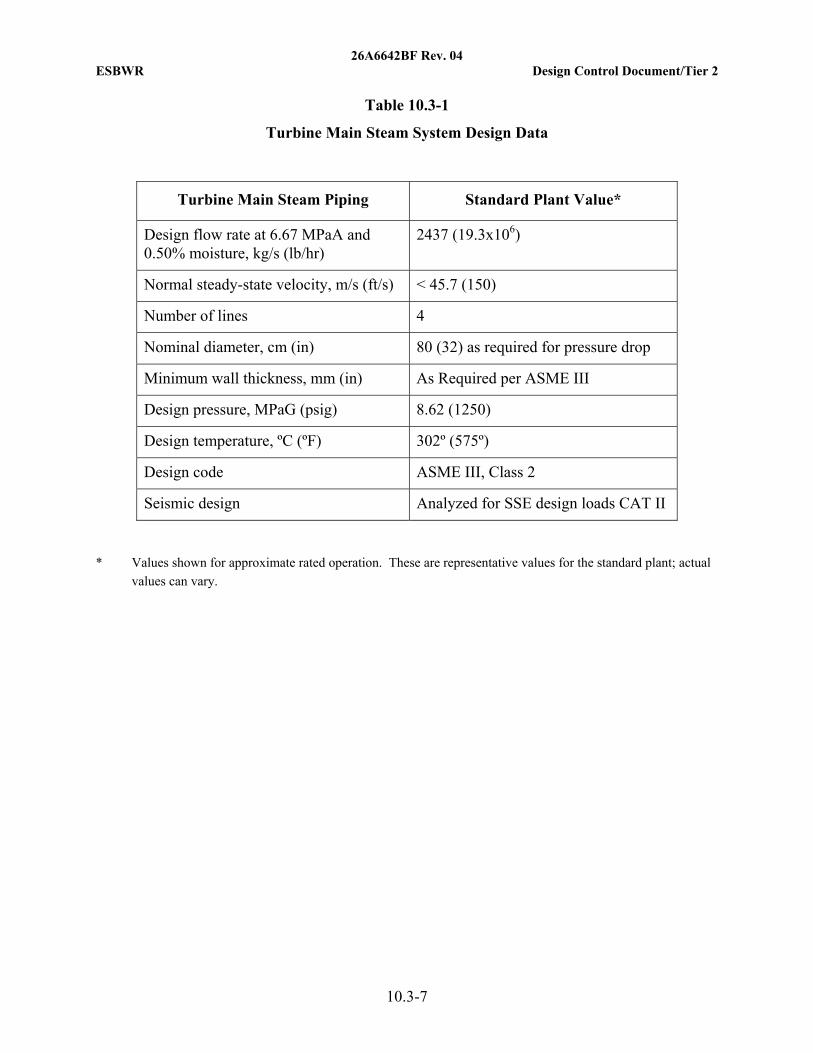
26A6642BF Rev. 04 ESBWR Design Control Document/Tier 2
10.3-7
Table 10.3-1
Turbine Main Steam System Design Data
Turbine Main Steam Piping Standard Plant Value*
Design flow rate at 6.67 MPaA and 0.50% moisture, kg/s (lb/hr)
2437 (19.3x10⁶)
Normal steady-state velocity, m/s (ft/s) < 45.7 (150)
Number of lines 4
Nominal diameter, cm (in) 80 (32) as required for pressure drop
Minimum wall thickness, mm (in) As Required per ASME III
Design pressure, MPaG (psig) 8.62 (1250)
Design temperature, ºC (ºF) 302º (575º)
Design code ASME III, Class 2
Seismic design Analyzed for SSE design loads CAT II
* Values shown for approximate rated operation. These are representative values for the standard plant; actual values can vary.

26A6642BF Rev. 04 ESBWR Design Control Document/Tier 2
10.3-1
Table 10.3-2
ASME Section III Class 2 Steam and Feedwater System Piping Materials
Component Form Material Specification (ASTM/ASME)
Main Steam System
Steam Pipe Seamless Carbon Steel SA-333, Grade 6
Forgings Carbon Steel SA 350, Grade LF2 or SA-508, Grade 1 Steam Pipe
Fittings Fittings Carbon Steel SA-420, Grade WPL-6
Feedwater System
Pipe Seamless Low Alloy SA-335, Grade P22
Fittings Forging Low Alloy SA-336, Grade F22
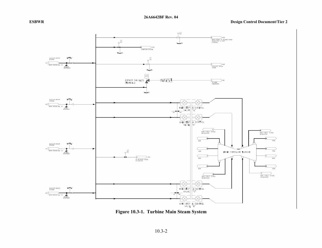
26A6642BF Rev. 04 ESBWR Design Control Document/Tier 2
10.3-2
Figure 10.3-1. Turbine Main Steam System
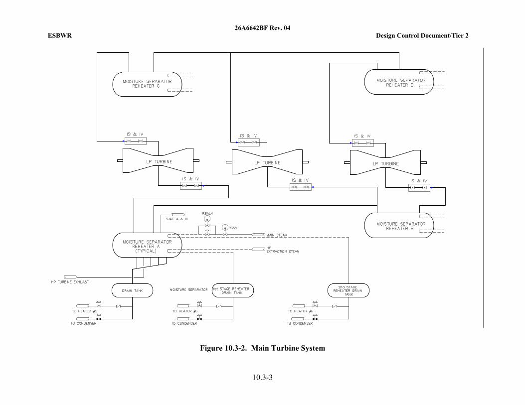
26A6642BF Rev. 04 ESBWR Design Control Document/Tier 2
10.3-3
Figure 10.3-2. Main Turbine System

26A6642BF Rev. 04 ESBWR Design Control Document/Tier 2
10.4-1
10.4 OTHER FEATURES OF STEAM AND POWER CONVERSION SYSTEM
This section provides discussions of each of the principal design features of the Steam and Power Conversion System not described elsewhere in this chapter.
10.4.1 Main Condenser
The main condenser is the steam cycle heat sink. During normal operation, the main condenser receives, condenses, deaerates, and holds up for N16 decay, the main turbine exhaust steam. It performs the same functions for the turbine bypass steam whenever the turbine bypass system is operated. The main condenser is also a collection point for other steam cycle miscellaneous drains and vents.
The main condenser is utilized as a heat sink in the initial phase of reactor cooldown during a normal plant shutdown.
10.4.1.1 Design Bases
10.4.1.1.1 Safety (10 CFR 50.2) Design Bases
The main condenser does not perform, support or ensure any safety-related function, and thus has no safety design bases. It is, however, designed with necessary shielding and controlled access to protect plant personnel from radiation. In addition, the main condenser hotwell provides a hold-up volume for Main Steam Isolation Valve (MSIV) fission product leakage. The condenser supports and anchors are designed to maintain condenser integrity following a Safe Shutdown Earthquake (SSE) (see Table 3.2-1, System N61).
For evaluation against GDC 60, see Subsection 3.1.6.1.
10.4.1.1.2 Non-Safety Power Generation Design Bases
• The main condenser is designed to function as the steam cycle heat sink and the collection point for miscellaneous drains and vents.
• The main condenser is designed to accommodate the turbine bypass steam flow following a full load rejection.
• The main condenser is designed to minimize air in-leakage and provides for the separation of noncondensable gases from the condensing steam and their removal by the Main Condenser Evacuation System (MCES, Subsection 10.4.2).
• At minimum normal operating hotwell water level, and normal full load condensate flow rate, the condenser provides a two-minute minimum condensate hold up time for N16 decay.
• The main condenser provides for deaeration of the condensate, such that condensate dissolved oxygen content is normally less than 15 ppb during operation above 50% load.
• The guidance provided in Reference 10.4-1 is considered in the condenser design.

26A6642BF Rev. 04 ESBWR Design Control Document/Tier 2
10.4-2
10.4.1.2 Description
10.4.1.2.1 General Description
The main condenser for the ESBWR standard plant design is a multi-pressure, three-shell, deaerating unit. Each shell is located beneath its respective low pressure turbine.
The three condenser shells are designated as the low pressure shell, the intermediate pressure shell, and the high pressure shell. Each standard design shell has two tube bundles. Circulating water flows in series through the three single-pass shells (Figure 10.4-1).
Vertical partition plate(s) divide each condenser shell hotwell longitudinally. Condensate channels interconnect the hotwells of the three shells. The condensate pumps take suction from the high pressure condenser hotwell (see Figure 10.1-1).
The condenser shells are located below the Turbine Building operating floor and are supported on the Turbine Building base mat. Expansion joints or welds are provided between each turbine exhaust opening and the steam inlet connections of the condenser shell. In the standard plant design, the three low pressure feedwater heaters are located in the steam dome of each shell. Piping is installed for hotwell level control and condensate sampling. The flooding evaluation is within Section 3.4.
10.4.1.2.2 Component Description
Table 10.4-1 provides ESBWR standard plant condenser design data that is typical of condensers operating with closed loop circulating water systems. Nothing in this section precludes the use of a single pressure condenser and parallel (instead of series) or alternate circulating water system.
10.4.1.2.3 System Operation
During plant operation, steam expanding through the low pressure turbine is directed downward into the condenser through the exhaust openings in the bottom of the turbine casings and is condensed. The condenser also serves as a heat sink for several other flows such as cascading heater drains and miscellaneous turbine cycle drains and vents.
Other flows occurring periodically or continuously originate from:
• The minimum recirculation flows of the condensate pumps,
• Feedwater line startup flushing,
• Steam cycle equipment vents and drains,
• Low-point drains,
• Condensate storage clean up feed and bleed, and
• Makeup, etc.
During Anticipated Operational Occurrence (AOO) conditions, the condenser is designed to receive turbine bypass steam and high level dump from the feedwater heaters and moisture separator and reheater drain tanks. The condenser is also designed to receive relief valve discharges and any necessary venting from MSR vessels, feedwater heater shells, gland seal

26A6642BF Rev. 04 ESBWR Design Control Document/Tier 2
10.4-3
steam header, steam seal regulator, sampling system and various other steam and liquid supply lines. Spray pipes and baffles are designed to provide protection of the condenser tubes and components from high-energy inputs to the condenser. The condensate is pumped from the condenser hotwell by the condensate pumps described in Subsection 10.4.7.
Because the main condenser shells normally operate at a vacuum, air leakage is into the shell side of the main condenser. Provision is made for detection of circulating water leakage into the shell side of the main condenser. Water leakage is detected by measuring the conductivity of sample water extracted at selected locations in the hotwell. Sampling methods are described in Subsection 9.3.2. During normal operation, radioactive leakage to the atmosphere via circulating water does not occur.
Air in-leakage and noncondensable gases, including hydrogen and oxygen gases contained in the turbine exhaust steam due to radiolysis of water in the reactor, are collected in the condenser from which they are removed by the Main Condenser Evacuation System described in Subsection 10.4.2.
The condenser and water boxes are welded carbon steel or low alloy ferrite steel. The tubes are stainless steel or titanium with compatible stainless steel or titanium clad carbon steel tube sheets depending on circulating water chemistry. The condenser is cooled by the circulating water system, as described in Subsection 10.4.5. Valves are provided in the circulating water system to permit a portion of the condenser to be isolated and removed from service.
Condensate is retained in the main condenser to permit radioactive decay before entering the condensate system. During normal power operation, the condensate is deaerated to reduce the level of dissolved oxygen to the required concentration before leaving the condenser.
Hotwell level controls provide automatic or manual makeup or rejection of condensate to maintain a normal level in the condenser hotwells. On low hotwell water level, the makeup control valve(s) opens and admits condensate to the hotwell from the condensate storage tank. When the hotwell level is brought to within normal operating range, the valve(s) closes. On high water level in the hotwell, the condensate reject control valve can open to divert condensate from the condensate pump discharge (downstream of the demineralizers and Gland Steam, Steam Jet Air Ejector and Off gas condensers) to the condensate storage tank; rejection can be stopped when the hotwell level falls to within the required operating range. This subsystem can be used to feed and bleed the Condensate Storage Tank (CS/CST) as needed. The hotwell level signals and controller are at least triple and dual redundant, respectively, to ensure availability of the condensate pumps.
During the initial cooling period after plant shutdown, the main condenser removes residual heat from the reactor via the turbine bypass system. However, if the condenser is not available to receive steam via the turbine bypass system, the reactor can still be safely cooled down using only Nuclear Island systems.
10.4.1.3 Evaluation
During normal operation, radioactive steam, gases and condensate are present in the shells of the main condenser. The anticipated inventory of radioactive contaminants during operation and shutdown is discussed in Sections 11.1 and 11.3.

26A6642BF Rev. 04 ESBWR Design Control Document/Tier 2
10.4-4
Necessary shielding and controlled access for the main condenser are provided (Sections 12.1 and 12.3).
Hydrogen buildup during operation is not expected to occur due to provisions for continuous evacuation of the main condenser. During shutdown, significant hydrogen buildup in the main condenser does not occur, because the main condenser is not receiving enough steam flow to cause significant hydrogen buildup.
The main condenser tube side circulating water is treated as required to limit fouling and prevent long-term corrosion of the tubes and other components. Corrosion of the outside of the condenser tubing is limited by maintaining water quality using the condensate purification system described in Subsection 10.4.6. The construction materials used for the main condenser are selected such that the potential for galvanic corrosion and other effects is minimized.
The potential flooding which would result from failure of the condenser is discussed in Section 3.4, which shows that failure of the condenser does not adversely affect any equipment required for safe shutdown of the reactor.
The loss of main condenser vacuum causes a turbine trip, reactor scram, bypass valve closure, and closure of the MSIVs. The effects of a turbine trip are discussed in Chapter 15. If the turbine stop, control or bypass valves fail to close on loss of condenser vacuum, rupture diaphragms on each turbine exhaust hood protect the condenser and turbine exhaust hoods against overpressure.
10.4.1.4 Tests and Inspections
Each condenser shell receives a field hydrostatic test before initial operation. This test consists of filling the condenser shell to the required level with water and, at the resulting static head, inspecting all tube to tube sheet joints, accessible welds, and surfaces for visible leakage and/or excessive deflection. Each condenser water box receives a field hydrostatic test for all visually inspectable joints and external surfaces.
10.4.1.5 Instrumentation Applications
10.4.1.5.1 Hotwell Water Level
The condenser hotwell water level is normally measured by at least three level transmitters. These transmitters provide signals to the Nonsafety-Related Distributed Control Information System (N-DCIS) for display, alarm, and hotwell level control. Level is controlled by two sets of modulating control valves. Each set consists of a normal and an emergency valve.
One set of valves allows water to flow from the condensate storage tank to the condenser hotwell as the level drops below the setpoint. If the level increases above another setpoint, the second set of valves located on the discharge of the condensate pumps opens to allow condensate to be pumped back to the storage tank. If desired, these valves may be used to feed and bleed water to the CS/CST.
10.4.1.5.2 Pressure
Nonsafety-related condenser pressure instruments provide signals to the N-DCIS for display, alarm, turbine trip, and bypass valve closure. In addition, four independent safety-related

26A6642BF Rev. 04 ESBWR Design Control Document/Tier 2
10.4-5
condenser pressure instruments, included in the Reactor Protection System (RPS), provide signals to trip the reactor and to isolate the reactor on high condenser pressure. These safety-related pressure instruments are located above the flood level in the Turbine Building.
As condenser pressure increases above normal levels, an alarm is activated. A further increase in pressure results in a turbine trip and reactor scram. As pressure increases toward a complete loss of vacuum, the main steam isolation valves and the turbine bypass valves are closed to prevent overpressurization of the condenser shell. Ultimate overpressure protection for the condenser is provided by rupture discs on the low pressure turbine casings.
The approximate set points for these functions are provided in Table 10.4-1.
10.4.1.5.3 Temperature
Temperature is measured in each Low Pressure (LP) turbine exhaust hood by temperature sensors. Controllers modulate control valve(s) in the water spray line protecting the exhaust hoods from overheating.
Circulating water temperatures are monitored upstream and downstream of each condenser tube bundle and are fed to the plant computer and the main control room instrumentation for use during periodic condenser performance evaluations.
10.4.1.5.4 Leakage
Leakage of circulating water into the condenser shell is monitored by the online instrumentation and the process sampling system described in Subsection 9.3.2.
Condensate conductivity is monitored at selected locations in the condenser. Conductivity and selected impurities are monitored at the discharge of the condensate pumps. High condensate conductivity or impurity content, which indicate a condenser tube leak, can be individually alarmed in the main control room.
Condenser tube leaks are located with tracer gases or other appropriate means and repaired as needed to support plant chemistry control. Condensate purity is controlled and maintained via the Condensate Purification System (CPS) as discussed in Subsection 10.4.6.
10.4.2 Main Condenser Evacuation System
Noncondensable gases are removed from the power cycle by the MCES. The MCES removes the hydrogen and oxygen produced by radiolysis of water in the reactor, and other power cycle noncondensable gases. The MCES exhausts to the Offgas System (OGS) during normal power operation and to the Turbine Building Compartment Exhaust (TBCE) subsystem during startup and shutdown (see Turbine Building HVAC system description in Subsection 9.4.4).
10.4.2.1 Design Bases
10.4.2.1.1 Safety (10 CFR 50.2) Design Bases
The Main Condenser Evacuation System does not perform, ensure or support any safety-related function, and thus, has no safety design bases.

26A6642BF Rev. 04 ESBWR Design Control Document/Tier 2
10.4-6
10.4.2.1.2 Non-Safety Power Generation Design Bases
• The MCES is designed to remove air and other power cycle noncondensable gases from the condenser during plant startup, cool down, and power operation and exhaust them to the OGS or TBCE subsystem.
• The MCES establishes a vacuum in the condenser during early startup and as required when the unit is shutdown with mechanical vacuum pumps.
• The MCES maintains a vacuum in the condenser during power operation by the use of steam jet air ejectors.
10.4.2.2 Description
For the MCES components that may contain radioactive materials, Regulatory Guides 1.33 and 1.28, as they relate to the quality assurance programs, are applied. The applicability of Regulatory Guide 1.33 during construction and operation is addressed in Section 17.2.
The components of the Main Condenser Evacuation System are designed to Quality Group D as defined in Regulatory Guide 1.26. MCES components are not designed to SSE seismic design standards. The quality standards meet the requirements of 10 CFR 50.55a for water and steam-containing components that may contain radioactive materials but are not part of the reactor coolant pressure boundary.
The MCES (Table 10.4-2 and Figure 10.4-2) consists of two 100%-capacity Steam Jet Air Ejector (SJAE) units for power operation, and two 50%-capacity (minimum) mechanical vacuum pumps for use during startup and shutdown. One SJAE unit is normally in operation and the other is in standby or they can be operated simultaneously in partial load.
During the initial phase of startup, when the desired rate of air and gas removal exceeds the capacity of the steam jet air ejectors, the mechanical vacuum pumps can be used to establish a vacuum in the main condenser and other parts of the power cycle. The discharge from the vacuum pumps is then routed to the TBCE system, because there is then little or no effluent radioactivity present. Process Radiation Monitoring System (PRMS) radiation detectors in the TBCE system and plant vent stack produce an alarm in the main control room if abnormal radioactivity is detected (Section 11.5). Radiation monitors are provided on the main steam lines, which trip and isolate the mechanical vacuum pump(s) if abnormal radioactivity is detected in the steam being supplied to the condenser.
The SJAEs are placed in service to remove the gases from the main condenser after vacuum is established in the main condenser by the mechanical vacuum pumps and when sufficient steam pressure is available.
During normal power operations, the SJAEs are normally driven by cross-around steam, with the main steam supply on automatic standby. The main steam supply is normally used during startup and low load operation. Auxiliary steam may be available for use of the SJAEs as an alternative to the main steam or if the mechanical vacuum pumps are unavailable.
10.4.2.3 Evaluation
The offgas from the main condenser is one source of radioactive gas in the station. Normally, it includes the activation gases nitrogen-16, oxygen-19, and nitrogen-13, plus the radioactive

26A6642BF Rev. 04 ESBWR Design Control Document/Tier 2
10.4-7
noble-gas parents of strontium-89, strontium-90, and cesium-137. An inventory of radioactive contaminants in the effluent from the SJAEs is evaluated in Section 11.3.
Steam and oxygen (or air) supply to the steam jet air ejector is maintained above a minimum flow to ensure adequate dilution of hydrogen and prevent the offgas from reaching the flammability limit of hydrogen. In addition, operation of the mechanical vacuum pumps is limited above specified reactor power levels to ensure the flammability limit of hydrogen is not reached.
The MCES, which is part of the main condenser and auxiliaries system, has no safety-related function (see Table 3.2-1) and does not interface with any safety-related structure, system or component. Thus, failure of the system would not compromise any safety-related system or components required for safe reactor shutdown.
Should the condenser in-leakage increase or evacuation system fail completely, a gradual reduction in condenser vacuum would result from the buildup of noncondensable gases. This reduction in vacuum would first cause a lowering of turbine cycle efficiency due to the increase in turbine exhaust pressure. If the MCES remains unavailable or has insufficient capacity for increased in-leakage, condenser pressure could reach the turbine trip set point and a turbine trip would result. The loss of condenser vacuum incident is discussed in Section 15.2.
10.4.2.4 Tests and Inspections
Testing and inspection of the system is performed prior to plant operation in accordance with applicable codes and standards.
Components of the system are monitored during operation to ensure satisfactory performance. Periodic inspections of the MCES are performed in conjunction with scheduled maintenance outages.
10.4.2.5 Instrumentation Applications
Local and/or remote indicating devices for parameters such as pressure, temperature, and flow are provided as required for monitoring system operation. Dilution steam, oxygen, or air flow, and vacuum pump and SJAE suction valve position indication are monitored in the main control room.
10.4.2.5.1 Steam Jet Air Ejectors
Ejector steam supply pressure and flow are monitored and controlled. Pressure controllers sense pressure and modulate the steam supply control valves upstream of the air ejectors. The flow transmitters provide inputs to logic devices for isolating the main condenser offgas flow to the air ejector unit on a two-out-of-three logic. This arrangement limits accumulation of explosive mixtures under low dilution flow conditions.
10.4.2.5.2 Mechanical Vacuum Pump
The vacuum pump exhaust streams are discharged to the TBCE subsystem. The PRMS provides for radiation monitoring of the system effluents prior to their release through the plant vent stack to the atmosphere.
Each vacuum pump is tripped and isolated upon receiving a main steam high radiation signal.

26A6642BF Rev. 04 ESBWR Design Control Document/Tier 2
10.4-8
10.4.3 Turbine Gland Seal System
The Turbine Gland Seal System (TGSS) reduces the escape of radioactive steam from the turbine shaft/casing penetrations and valve stems and limits air in-leakage through sub-atmospheric turbine glands.
10.4.3.1 Design Bases
10.4.3.1.1 Safety (10 CFR 50.2) Design Bases
The TGSS does not perform, ensure or support any safety-related function, and thus, has no safety design basis.
10.4.3.1.2 Non-Safety Power Generation Design Bases
• The TGSS is designed to limit atmospheric air leakage into the turbine casings and to minimize radioactive steam leakage out of the turbine glands and valves.
• The TGSS returns the condensed steam to the condenser and exhausts the noncondensable gases, via the TBCE subsystem, to the plant stack.
• The TGSS has sufficient capacity to handle steam and air flows resulting from greater than normal gland clearances.
10.4.3.2 Description
10.4.3.2.1 General Description
For the TGSS components that may contain radioactive materials, Regulatory Guides 1.33 and 1.28, as they relate to the quality assurance programs, are applied. The applicability of RG 1.33 during construction and operation is addressed within Section 17.2.
The TGSS provides for the collection and condensation of sealing steam and the venting of noncondensable gases. The components are designed to Quality Group D as defined in Regulatory Guide 1.26, and are not designed to SSE seismic design standards (see Section 3.2).
The TGSS is illustrated in Figure 10.4-3. The TGSS consists of sealing steam pressure controls, sealing steam header, gland steam condenser(s), with two full-capacity exhauster blowers, and the associated piping, valves and instrumentation.
10.4.3.2.2 System Operation
The annular space through which the turbine shaft penetrates the casing is sealed by steam supplied to the shaft seals. Where the gland seals operate against positive pressure, the sealing steam flows either inwards for collection at an intermediate leak-off point or outwards and into the vent annulus. Where the gland seals operate against vacuum, the sealing steam either is drawn into the casing or leaks outward to a vent annulus. At all gland seals, the vent annulus is maintained at a slight vacuum, and receives air in-leakage from the outside. From each vent annulus, the air-steam mixture is drawn to the gland steam condenser.
The seal steam header pressure is regulated automatically by redundant pressure controllers. During startup and low load operation, the seal steam can be supplied from the Auxiliary Boiler System (ABS). At all loads, gland sealing can be achieved using clean steam directly from the
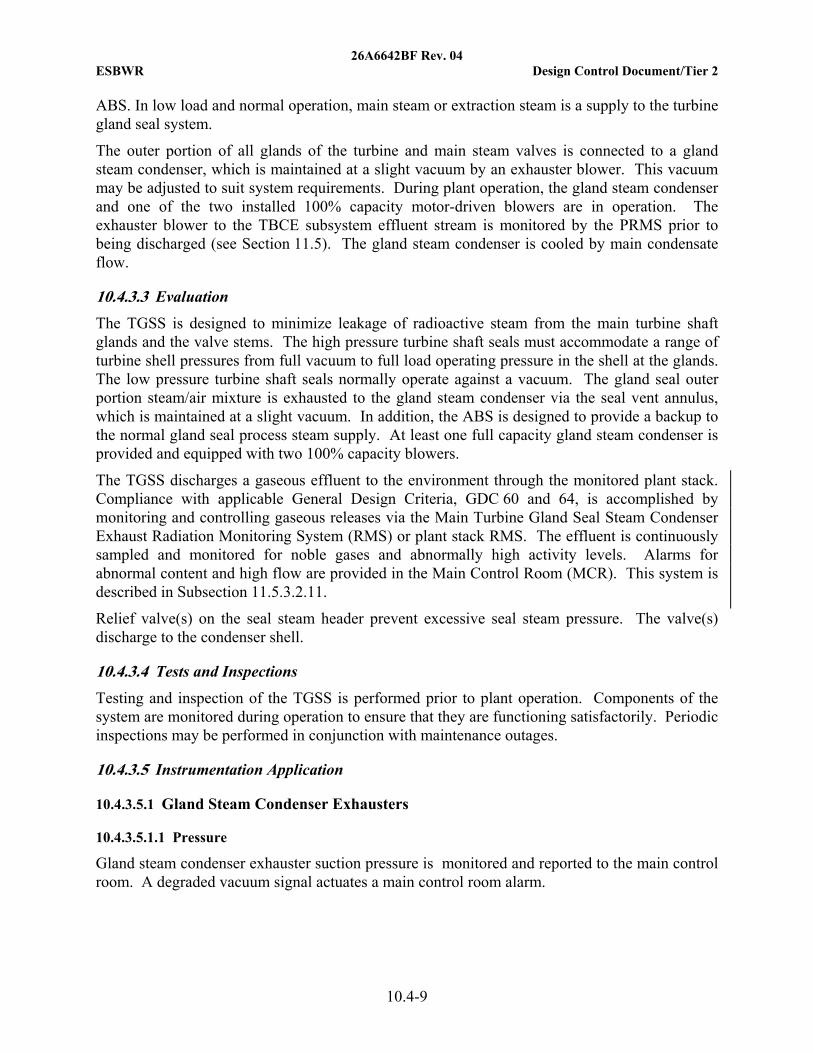
26A6642BF Rev. 04 ESBWR Design Control Document/Tier 2
10.4-9
ABS. In low load and normal operation, main steam or extraction steam is a supply to the turbine gland seal system.
The outer portion of all glands of the turbine and main steam valves is connected to a gland steam condenser, which is maintained at a slight vacuum by an exhauster blower. This vacuum may be adjusted to suit system requirements. During plant operation, the gland steam condenser and one of the two installed 100% capacity motor-driven blowers are in operation. The exhauster blower to the TBCE subsystem effluent stream is monitored by the PRMS prior to being discharged (see Section 11.5). The gland steam condenser is cooled by main condensate flow.
10.4.3.3 Evaluation
The TGSS is designed to minimize leakage of radioactive steam from the main turbine shaft glands and the valve stems. The high pressure turbine shaft seals must accommodate a range of turbine shell pressures from full vacuum to full load operating pressure in the shell at the glands. The low pressure turbine shaft seals normally operate against a vacuum. The gland seal outer portion steam/air mixture is exhausted to the gland steam condenser via the seal vent annulus, which is maintained at a slight vacuum. In addition, the ABS is designed to provide a backup to the normal gland seal process steam supply. At least one full capacity gland steam condenser is provided and equipped with two 100% capacity blowers.
The TGSS discharges a gaseous effluent to the environment through the monitored plant stack. Compliance with applicable General Design Criteria, GDC 60 and 64, is accomplished by monitoring and controlling gaseous releases via the Main Turbine Gland Seal Steam Condenser Exhaust Radiation Monitoring System (RMS) or plant stack RMS. The effluent is continuously sampled and monitored for noble gases and abnormally high activity levels. Alarms for abnormal content and high flow are provided in the Main Control Room (MCR). This system is described in Subsection 11.5.3.2.11.
Relief valve(s) on the seal steam header prevent excessive seal steam pressure. The valve(s) discharge to the condenser shell.
10.4.3.4 Tests and Inspections
Testing and inspection of the TGSS is performed prior to plant operation. Components of the system are monitored during operation to ensure that they are functioning satisfactorily. Periodic inspections may be performed in conjunction with maintenance outages.
10.4.3.5 Instrumentation Application
10.4.3.5.1 Gland Steam Condenser Exhausters
10.4.3.5.1.1 Pressure
Gland steam condenser exhauster suction pressure is monitored and reported to the main control room. A degraded vacuum signal actuates a main control room alarm.

26A6642BF Rev. 04 ESBWR Design Control Document/Tier 2
10.4-10
10.4.3.5.1.2 Level
Water levels in the gland steam condenser drain leg are monitored and makeup is added as required to maintain loop seal integrity. Abnormal levels are alarmed in the main control room.
10.4.3.5.1.3 Effluent Monitoring
The TGSS effluents are normally monitored by a system-dedicated radiation monitor installed on the gland steam condenser exhauster blower discharge. High monitor readings are alarmed in the main control room. The system effluents are then discharged to the TBCE subsystem and the plant stack, where further effluent radiation monitoring is performed. (See Section 12.2 for the radiological analysis of the TGSS effluents).
10.4.3.5.2 Sealing Steam Header
Sealing steam header pressure and temperature instruments send signals to the N-DCIS for display, alarm, and recording.
10.4.4 Turbine Bypass System
The Turbine Bypass System (TBS), in combination with the Steam Bypass and Pressure Control System (SB&PC), provides the capability to discharge main steam from the reactor via the Turbine Main Steam System (TMSS) directly to the condenser to minimize step load reduction transient effects on the Nuclear Boiler System (NBS). The TBS is also used to discharge main steam during reactor hot standby and cool-down operations. Operation of the TBS eliminates the need to rely solely on safety-related systems for shutting down the plant during normal operations.
The TBS satisfies General Design Criterion 4 in that failure of the TBS due to a pipe break or malfunction of the TBS would not adversely affect any safety-related system or component (i.e., those necessary for safe shutdown or accident prevention or mitigation). The TBS has no essential systems or components, as defined in BTP SPLB 3-1.
10.4.4.1 Design Bases
10.4.4.1.1 Safety (10 CFR 50.2) Design Bases
The TBS does not perform, ensure or support any safety-related function. However, it does mitigate the effects of AOOs (which are defined as part of normal operation in 10 CFR 50 Appendix A and General Design Criterion 10) and Anticipated Transients Without Scram events, if some of the MSIVs remain open and the main turbine stop/control valves are closed. The TBS is analyzed to demonstrate structural integrity under SSE loading conditions.
10.4.4.1.2 Non-Safety Power Generation Design Bases
• The TBS has a design capacity of 110% of the rated main steam flow.
• The TBS is designed to bypass steam to the main condenser during plant startup and to permit a normal cooldown of the reactor from a hot shutdown condition to a point appropriate for the transition to shutdown cooling operation.

26A6642BF Rev. 04 ESBWR Design Control Document/Tier 2
10.4-11
• The TBS is designed, in conjunction with other reactor systems, to provide for a full load rejection or turbine trip without lifting of the reactor SRVs and without reactor trip.
• No single failure can disable more than 50% of the installed bypass capacity.
10.4.4.2 Description
10.4.4.2.1 General Description
The TBS in the ESBWR standard plant design comprises Turbine Bypass Valves (TBVs) connected to the TMSS Main Steam Lines via TMSS system piping. The outlets of TBVs are connected to the Main Condenser via pressure reducers. The system and its components are shown in Figure 10.3-1.
The TBS, in combination with the reactor systems, provides the capability to shed 100% of the TG rated load without the operation of SRVs and without reactor trip.
The SB&PC, which controls the TBS, is provided with an uninterruptible redundant power source. The worst case of an AOO with a single failure would result in a loss of no more than 50% of bypass capacity. The TBS has a design capacity of 110% of rated main steam flow. Failure of a single TBV to open does not result in a system capacity less than 100% of rated main steam flow.
10.4.4.2.2 Component Description
Each bypass valve is operated by hydraulic fluid pressure with spring action to close. The valve assembly includes hydraulic supply and drain piping, hydraulic accumulator(s), servo valve(s), fast acting solenoid valve(s), and valve position transmitters.
The turbine bypass valves are operated by the turbine hydraulic fluid power unit. It is possible to isolate the high pressure fluid to the turbine valves while supplying hydraulic fluid to the bypass valves. High pressure hydraulic fluid is provided to the valve actuators and is drained back to the fluid reservoir.
10.4.4.2.3 System Operation
The turbine bypass valves are opened by redundant signals received from the SB&PC System whenever the actual steam pressure exceeds the setpoint by a small margin. This occurs when the amount of steam generated by the reactor cannot be entirely used by the turbine. This bypass demand signal causes fluid pressure to be applied to the operating cylinder, which opens the first of the individual valve(s). As the bypass demand increases, additional bypass valves are opened, dumping the steam to the condenser. The bypass valves are equipped with fast acting solenoid valves to allow rapid opening of bypass valves upon turbine trip or generator load rejection.
The bypass valves automatically trip closed whenever the condenser pressure increases to a preset value. Individual bypass valves close on loss of electrical power or hydraulic system pressure to their operator. Bypass valve hydraulic accumulators have the capacity to open the associated valve for at least six seconds with hydraulic power unit failure. The bypass valve accumulators are equipped with check valves so that no single hydraulic supply failure can disable more than 50% of the installed bypass capacity.

26A6642BF Rev. 04 ESBWR Design Control Document/Tier 2
10.4-12
When the plant is at zero power, hot standby or initial cool-down, the system is operated manually by the control room operator or by the Plant Automation System (PAS). The measured reactor pressure is then compared against, and regulated to, the pressure set by the operator or automation system.
The turbine bypass control system can malfunction in either the open or closed mode, but requires multiple failures to do so. The effects of these potential failure modes on the NSSS and turbine generator system are addressed in Chapter 15. If the bypass valves fail open, additional heat load is placed on the condenser. If this load is great enough, the turbine is tripped on degraded condenser vacuum. If the bypass valves fail closed, the NBS relief valves and the Isolation Condenser System permit controlled cool-down of the reactor.
The turbine bypass system valves and piping conform to the applicable quality standards as referenced in Section 3.2.
10.4.4.3 Evaluation
The TBS does not perform or support any safety-related function. There is no safety-related equipment in the close vicinity of the TBS, except four position sensors at each bypass valve that provide valve status to the RPS logic. These safety-related bypass valve position sensors are fail-safe such that they cannot prevent actuation of the reactor protection function. All high-energy lines of the TBS are located in the Turbine Building. The TBS has no essential system or component as defined in BTP SPLB 3-1.
The effects of a malfunction of the turbine bypass system valves and the effects of such a failure on other systems and components are evaluated in Chapter 15.
10.4.4.4 Inspection and Testing Requirements
Before the TBS is placed in service, all turbine bypass valves are tested for operability. The steam lines are hydrostatically tested to confirm leak-tightness. Pipe weld joints are inspected in accordance with ASME III, Class 2 requirements upstream and ASME B31.1 downstream of the bypass valve(s). The bypass valves are tested while the unit is in operation. Periodic tests and inspections are performed within a preventive maintenance program in accordance with manufacturer’s recommendations and industry practice.
10.4.4.5 Instrumentation Applications
Main steam pressure is redundantly measured in the reactor steam area by pressure transmitters. Under normal conditions a validated pressure signal is used by the SB&PC System. If one of the signals fails, an alarm activates, but the bypass control and/or reactor pressure regulation is unaffected.
Input to the system also includes load demand and load reference signals from the turbine speed load control system. The SB&PC system uses these signals to position the turbine control valves (via the Turbine Generator Control System) and the TBVs. A complete description of the turbine bypass valve control system is included within Chapter 7.

26A6642BF Rev. 04 ESBWR Design Control Document/Tier 2
10.4-13
10.4.5 Circulating Water System
The Circulating Water System (CIRC) provides cooling water for removal of the power cycle heat from the main condensers and transfers this heat to the Normal Power Heat Sink (NPHS).
The CIRC does not interface with any safety-related structure, system or component, and no CIRC failure could adversely affect any safety-related structure, system or component. (See Subsection 10.4.5.3 for flooding analysis).
10.4.5.1 Design Bases
10.4.5.1.1 Safety (10 CFR 50.2) Design Bases
The CIRC does not perform, ensure or support any safety-related function, and thus, has no safety design bases.
10.4.5.1.2 Non-Safety Power Generation Design Bases
• The CIRC supplies cooling water at a sufficient flow rate to condense the steam in the condenser, as required for plant operation.
• The CIRC is automatically isolated in the event of gross leakage into the Turbine Building condenser area to prevent flooding of the Turbine Building (see Subsection 10.4.5.6).
• The CIRC normally supplies cooling water at a sufficient flow to accommodate full load rejection without exceeding the condenser pressure turbine trip setpoint and without reactor scram.
10.4.5.2 Description
10.4.5.2.1 General Description
The portion of the Circulating Water System (Figure 10.4-1) in the scope of the ESBWR standard plant consists of the following components.
• Condenser water boxes and piping and valves, and
• Water box drain subsystem.
Table 10.4-3 includes the NPHS temperature range for water entering the CIRC and water delivered by the CIRC to the main condenser.
The cooling water is circulated by motor-driven pumps. The quantity and capacity of the pumps are plant specific.
For the ESBWR CIRC conceptual design, four pumps are arranged in parallel. Discharge lines combine into two parallel main circulating water supply lines to the main condenser. Each circulating water supply line connects to an inlet water box on the low pressure condenser. An interconnecting line fitted with a butterfly valve is provided to connect both circulating water supply lines. The discharge of each pump is fitted with a remotely operated valve. This arrangement permits isolation and maintenance of any one pump while the others remain in operation and minimizes the backward flow through a tripped pump.

26A6642BF Rev. 04 ESBWR Design Control Document/Tier 2
10.4-14
The CIRC and condenser are designed to permit isolation of each set of the three series connected tube bundles to permit repair of leaks and cleaning of water boxes while operating at reduced power.
The CIRC includes water box vents to help fill the condenser water boxes during startup and remove accumulated air and other gases from the water boxes during normal operation.
A chemical additive subsystem may also be provided to prevent the accumulation of biological growth and chemical deposits within the wetted surfaces of the system. Other non-chemical cleaning systems may be used as needed.
10.4.5.2.2 Component Description
Codes and standards applicable to the CIRC are listed in Section 3.2. The system is designed and constructed in accordance with quality Group D specifications.
Table 10.4-3 provides reference parameters for the major components of the CIRC.
10.4.5.2.3 System Operation
The CIRC provides a continuous flow of cooling water to the condenser as required to support startup, shutdown, and operating loads. One or more pumps may be taken out of service depending on plant load and operating conditions. Pump and condenser isolation valve actuation are controlled by local controls and/or controls located in the main control room.
The circulating water pumps are tripped and the pump and condenser isolation valves as well as the circulating lines interconnecting valve are closed in the event of a system isolation signal from the Turbine Building condenser area high water level switch(es). Level switches are provided in the Turbine Building condenser area and the water level trip is initiated upon high level detection. A Turbine Building condenser area high level alarm is provided in the control room prior to reaching the trip level setpoint.
The water level trip is set high enough to prevent inadvertent plant trips from unrelated failures, such as a sump overflow. A reliable logic scheme is used (e.g., two-out-of-three logic) to minimize potential for spurious isolation trips.
10.4.5.3 Evaluation
The CIRC is not a safety-related system. However, a flooding analysis of the Turbine Building is performed on the CIRC (see Section 3.4 and Subsection 10.4.5.6).
10.4.5.4 Tests and Inspections
The CIRC and related systems and facilities are tested and checked for acceptable leakage integrity prior to initial plant startup and, as appropriate, following major maintenance.
Selected portions of the CIRC are accessible for inspection and maintenance/testing during normal power operation.
10.4.5.5 Instrumentation Applications
Temperature monitors are provided upstream and downstream of each condenser shell section.

26A6642BF Rev. 04 ESBWR Design Control Document/Tier 2
10.4-15
Indication is provided in the control room to identify open and closed positions of remotely operated valves in the CIRC piping.
Major CIRC valves, which control the flow path, are operated by local controls or by remote controls located at the main control room. The pump discharge isolation valves are interlocked with the circulating water pumps so that when a pump is started, its discharge valve is opening while the pump is coming up to speed, thus assuring that there is water flow through the pump. When a pump is stopped or trips, the discharge valve closes automatically to prevent or minimize backward rotation of the pump and motor.
Monitoring of the performance of the Circulating Water System is accomplished by differential pressure transducers located on each condenser waterbox with indication provided in the main control room. Temperature signals from the supply and discharge sides of the condenser are transmitted to the N-DCIS for recording, display and condenser performance calculations.
Temperature elements, located in each condenser supply line and monitored in the main control room, are utilized in throttling the warm water recirculation valve to maintain the minimum inlet temperature of approximately 5ºC (41ºF).
10.4.5.6 Flood Protection
Level switches are provided in the Turbine Building to trip the CIRC pumps and close the required valves in case of a CIRC system component failure. The flooding signal initiates from a high water level detection. In the hypothetical situation of a circulating water system pipe or expansion joint failure, if not detected and isolated, the water discharged would cause internal Turbine Building flooding above grade level, with excess water potentially spilling over on site. If a failure occurred within a condensate system (condenser shell side), the resulting flood level would be below grade level due to the relatively small hotwell inventory relative to the Turbine Building capacity.
Failure of other systems that have piping or components inside the Turbine Building, such as the Turbine Component Cooling Water System, Reactor Component Cooling Water System and Plant Service Water System are discussed within Section 3.4.
10.4.5.7 Portions of the CIRC Outside the Scope of ESBWR Standard Plant Design
The conceptual design portions of the CIRC, i.e. those outside the ESBWR standard plant design, include the following:
• Normal Power Heat Sink;
• Pump and intake screen area;
• Pumps and pump discharge and interconnecting valves;
• CIRC piping outside the Turbine Building; and
• Related support facilities such as makeup water system, water treatment/chemical injection, tube cleaning system, inventory blow down, and required maintenance equipment.

26A6642BF Rev. 04 ESBWR Design Control Document/Tier 2
10.4-16
10.4.5.7.1 Safety (10 CFR 50.2) Design Basis (Interface Requirements)
None
10.4.5.7.2 Non-Safety Power Generation Design Bases (Interface Requirements)
Systems and components are included with the following interface considerations:
• Compatible design as described in Subsection 10.4.5.2.
• Evaluation per Subsection 10.4.5.3.
• Tests and inspections per Subsection 10.4.5.4.
• Instrument applications per Subsection 10.4.5.5.
• Flood protection per Subsection 10.4.5.6.
10.4.5.8 Normal Power Heat Sink (Conceptual Design)
The Normal Power Heat Sink is outside the ESBWR standard plant scope.
The conceptual design for the ESBWR Normal Power Heat Sink utilizes two natural-draft cooling towers. Water circulation, chemical control, and inventory blow down are all part of the conceptual Circulating Water System. Nothing in this section precludes the use of mechanical draft cooling towers or once-through cooling systems because these have no effect on the Nuclear Island.
10.4.6 Condensate Purification System
The Condensate Purification System (CPS) purifies and treats the condensate as required to maintain reactor feedwater purity. The CPS uses filtration to remove suspended solids, including corrosion products, and ion exchange to remove dissolved solids and other impurities.
10.4.6.1 Design Bases
10.4.6.1.1 Safety (10 CFR 50.2) Design Bases
The CPS does not perform, ensure or support any safety-related function, and thus, has no safety design bases.
10.4.6.1.2 Non-Safety Power Generation Design Bases
• The CPS removes dissolved and suspended solids from the condensate to maintain reactor feedwater quality.
• The CPS removes corrosion products from the condensate and from drains returned to the condenser hotwell, to limit accumulation of corrosion products in the cycle.
• The CPS removes impurities entering the power cycle due to condenser circulating water leaks as required to permit continued power operation within specified water quality limits as long as such condenser leaks are small and readily located and repaired.

26A6642BF Rev. 04 ESBWR Design Control Document/Tier 2
10.4-17
• The CPS limits the entry of dissolved solids into the feedwater system in the event of large condenser leaks, such as a tube break, to permit a reasonable amount of time for orderly plant shutdown.
• The CPS maintains the condensate storage tank water quality as required for condensate makeup and miscellaneous condensate supply services.
• The CPS flow controls and bypass are arranged such that the condensate system flow is uninterrupted even in the presence of a single failure.
10.4.6.2 System Description
10.4.6.2.1 General Description
The CPS (shown in Figure 10.4-5) consists of high efficiency filters arranged in parallel and operated in conjunction with a normally closed filter bypass. The CPS also includes bead resin ion exchange demineralizer vessels arranged in parallel. The number of filters and demineralizers are indicated in Table 10.4-4. A resin trap is installed downstream of each demineralizer vessel to preclude gross resin leakage into the power cycle in case of vessel resin retention screen failure. The CPS achieves the water quality effluent conditions required for reactor power operation defined in the water quality specification. The CPS components are located in the Turbine Building.
Provisions are included to permit cleaning and replacement of the ion exchange resin. Each of the demineralizer vessels has inlet and outlet isolation valves which are remotely controlled from the local and MCR control panel(s).
A demineralizer system bypass valve is also provided which is controlled from the local control panel or the main control room. Pressure downstream of the demineralizer or high demineralizer differential pressure is indicated and is alarmed in the main control room to alert the operator. The bypass is used during start-up and in an emergency and for a short period of time until the CPS flow is returned to normal or the plant is brought to an orderly shutdown.
10.4.6.2.2 Component Description
Codes and standards applicable to the CPS are listed in Section 3.2. The system is designed and constructed in accordance with quality Group D requirements. Design data for major components of the CPS are listed in Table 10.4-4.
• Condensate Filters - The CPS includes back-washable high efficiency filters.
• Condensate Demineralizers - demineralizer vessels are constructed of carbon steel and lined to minimize corrosion or leaching.
10.4.6.2.3 System Operation
The CPS is operated to maintain feedwater purity levels.
Full condensate flow is passed through the filters and demineralizers, each of which are piped in parallel. A filter or demineralizer may be in service, in standby, or out of service for maintenance. The service run of each demineralizer is terminated by either high differential pressure across the vessel, high effluent conductivity, high sodium effluent, volumetric

26A6642BF Rev. 04 ESBWR Design Control Document/Tier 2
10.4-18
throughput, or age. Alarms for some of these parameters are provided on the local control panel or the main control room.
The local control panel (and in some cases, the MCR) is equipped with the appropriate instruments and controls to allow the operators to perform the following operations:
• Remove a filter from service;
• Clean up the isolated filter by backwashing and place it back in operation;
• Remove an exhausted demineralizer from service and replace it with a standby unit;
• Open the bypass as needed during periods of abnormally high system differential pressure;
• Transfer the resin inventory of the isolated demineralizer vessel into the resin receiver tank for cleaning or disposal;
• Transfer the received resin bed from the receiver tank to the storage tank (alternately, load the storage tank(s) with fresh new resin);
• Transfer the resin storage tank resins to any isolated demineralizer vessel; and
• Transfer exhausted resin from the receiver tank to the radwaste system.
On termination of a demineralizer service run, the exhausted vessel is taken out of service and isolated, and the standby unit is placed in service from the local control panel. The resin from the exhausted vessel is transferred to the resin receiver tank and replaced by a clean resin bed that is transferred from the resin storage tank. A final rinse of the new bed is performed in the isolated vessel by condensate recycle before it is placed on standby or returned to service. The rinse can be monitored by conductivity analyzers; and the process is terminated when the required minimum rinse has been completed and normal clean bed conductivity is obtained and fines are reviewed from a grab sample.
To support automation, the CPS is designed to be operated with a constant number of on line demineralizers and filters from 25 to 100% power or to automatically sequence the filters and demineralizers as necessary to support any power level from 25 to 100%.
Through normal condensate makeup and reject, the condensate storage tank water inventory is processed through the CPS. Tank water quality is maintained as required for condensate makeup to the cycle and miscellaneous condensate supply services.
The condensate purification and related support system wastes are processed by the radwaste system, as described within Chapter 11.
10.4.6.3 Evaluation
The CPS does not perform, ensure or support any safety-related function.
The CPS removes condensate system corrosion products and impurities resulting from condenser tube leakage in addition to some radioactive material, activated corrosion products and fission products that are carried-over from the reactor. The concentration of such radioactive material in the CPS requires shielding (see Chapter 12). Wastes from the condensate purification system are collected in controlled areas and sent to the radwaste system for treatment and/or disposal.

26A6642BF Rev. 04 ESBWR Design Control Document/Tier 2
10.4-19
Chapter 11 describes the activity level and removal of radioactive material from the condensate system.
Chemistry threshold limits and administrative actions are established to mitigate chemistry excursions in the condensate system. The COL Applicant will provide threshold values and recommended operator actions for chemistry excursions in the condensate system (COL Item 10.4-1-A).
The CPS complies with Regulatory Guide 1.56.
The CPS and related support facilities are located in nonsafety-related buildings. Potential CPS equipment or piping failures do not adversely affect safety-related equipment or structures.
10.4.6.4 Tests and Inspections
Preoperational tests are performed on the CPS to ensure operability, reliability, and integrity of the system. Each filter and demineralizer vessel can be isolated during normal plant operation to permit testing and maintenance.
10.4.6.5 Instrumentation Applications
Conductivity elements are provided for the system influent and for each demineralizer vessel effluent and monitored at the local control panel or in the main control room. System influent conductivity elements detect condenser leakage and demineralizer effluent conductivity elements provide indication of resin exhaustion. The demineralizer effluent conductivity elements also monitor the quality of the condensate that is recycled through a standby vessel before it is returned to service. Differential pressure is monitored across each filter vessel, demineralizer vessel and discharge resin strainer to detect blockage of flow. The flow through each demineralizer is monitored and used as control input to assure even distribution of condensate flow through all operating vessels and by correlation with the vessel pressure drop, or flow, to permit evaluation of the vessel throughput capacity. Individual demineralizer vessel effluent conductivity, differential pressure, and flow measurements are monitored. Individual filter vessel pressure drop and flow data are provided at the system control panel(s). An indicator is included in the local panel and main control room to alarm abnormal conditions within the system.
The Process Sampling System monitors other water quality parameters as necessary for proper operation of the filters, demineralizers, and miscellaneous support services (see Subsection 9.3.2).
10.4.7 Condensate and Feedwater System
The Condensate and Feedwater System (C&FS) receives condensate from the condenser hotwell(s), supplies condensate to the condensate purification system, and delivers high purity Feedwater (FW) to the reactor, at the required flow rate, pressure and temperature.

26A6642BF Rev. 04 ESBWR Design Control Document/Tier 2
10.4-20
10.4.7.1 Design Bases
10.4.7.1.1 Safety (10 CFR 50.2) Design Bases
The C&FS does not perform, ensure or support any safety-related function, and thus, has no safety design basis.
10.4.7.1.2 Non-Safety Power Generation Design Bases
• The C&FS is designed to provide a dependable FW supply to the reactor at the required flow rate, pressure, and temperature under all anticipated steady-state and transient conditions.
• The C&FS is designed to supply at least 135% of the rated FW flow during anticipated operational occurrences.
• The C&FS is designed to permit long-term full power operation with one FW pump and/or one condensate pump out-of-service.
• The C&FS is designed to permit long-term operation with one low pressure heater string out of service at the maximum load permitted by the turbine manufacturer. This value is set by steam flow limitation on the affected low pressure turbine.
• The C&FS is designed to heat up the reactor FW to approximately 215.6ºC (420ºF) during normal full power operation.
• The C&FS is designed to assist in reactor power maneuvers via final feedwater temperature control.
• The C&FS is designed to cool the auxiliary condensers and support other auxiliary condensate loads.
• The C&FS is designed so that no single operator error or equipment failure causes more than a 55.6ºC (100ºF) decrease in final feedwater temperature.
• The C&FS, in conjunction with the Condensate Purification System, is designed to maintain water quality suitable for all plant conditions, including power operation, startup, shutdown and extended outages. The Condensate Purification System is discussed in Subsection 10.4.6.
• The C&FS is designed to allow for Final Feedwater Temperature Reduction (FFWTR) operation.
• During plant startups, the C&FS is designed to pump preheated FW to the Reactor Pressure Vessel (RPV) for the purpose of RPV initial heating if sufficient core decay heat is not available.
• All C&FS functions needed to support safe power operation are fault-tolerant and use at least dual redundant controllers and triple redundant signals.

26A6642BF Rev. 04 ESBWR Design Control Document/Tier 2
10.4-21
10.4.7.2 Description
10.4.7.2.1 General Description
The C&FS (Table 10.4-5 and Figure 10.1-1) consists of the piping, valves, pumps, heat exchangers, controls and instrumentation, and the associated equipment and subsystems that supply the reactor with heated FW in a closed steam cycle utilizing regenerative FW heating. The system described in this subsection extends from the main condenser outlet to (but not including) the seismic interface restraint outside of containment. The remainder of the system, extending from the restraint to the reactor, is described in Chapter 5. Turbine cycle steam is utilized for FW heating. The drains from each stage of the closed low pressure FW heaters are cascaded through successively lower pressure FW heaters to the main condenser. The high pressure heater drains are routed to the open feedwater tank. The cycle extraction steam, drains and vents systems are illustrated in Figures 10.4-6a, b and 10.4-7a, b.
The C&FS consists of four 33.3-37% capacity condensate pumps (three normally operating and one in standby), four 33.3-45% capacity reactor FW pumps (three normally in operation and one on automatic standby), three stages of low pressure closed FW heaters, an open FW heater (feedwater storage tank) and three (3) stages of high pressure FW heaters, piping, valves, and instrumentation. The condensate pumps take suction from the condenser hotwell(s) and discharge the deaerated condensate into one common header, which feeds the CPS. Downstream of the CPS, the condensate is taken by a single header, through the auxiliary condenser/coolers. The auxiliary condenser/coolers consist of the gland steam condenser(s), SJAE condenser(s) and offgas condenser(s). The condensate then branches into parallel strings of low pressure FW heaters. Each string contains three (3) stages of low pressure FW heaters. The strings join together at a common header, which is routed to the feedwater tank that supplies heated feedwater to the suction of the reactor FW pumps.
Another input to the feedwater tank consists of the cascaded drains from the high pressure FW heaters.
The reactor FW pumps discharge the FW into two parallel high pressure FW heater strings, each with three (3) stages of high pressure FW heating. The last stage (No. 7) of FW heating is used for final feedwater temperature control and is normally not in service. Downstream of the high pressure FW heaters, the two strings are then joined into a common header, which divides into two FW lines that connect to the reactor with six penetrations.
A bypass is provided around the FW tank and reactor FW pumps to permit supplying FW to the reactor during early startup without operating the FW pumps, using only the condensate pumps. During startup, RPV level is controlled by a low flow control valve with flow supplied by either the condensate pumps or via selected FW pump(s).
One more bypass, equipped with a flow control valve, provides a flow path around the high pressure heater(s) to facilitate maintenance or for reducing final FW temperature to extend the end of fuel cycle.
During power operation, the condensate is deaerated in the condenser and oxygen injection is used to maintain the desired level of oxygen content in the final FW.
To minimize corrosion product input to the reactor during startup, recirculation lines to the condenser are provided from the high pressure FW heater outlet header. Cleanup is also

26A6642BF Rev. 04 ESBWR Design Control Document/Tier 2
10.4-22
accomplished by allowing the system to recirculate through the condensate demineralizers for treatment prior to feeding water to the reactor during startup.
10.4.7.2.2 Component Description
All pressure retaining components of the C&FS are designed and constructed in accordance with applicable codes as referenced in Section 3.2.
10.4.7.2.2.1 Condensate Pumps
The four condensate pumps are identical, fixed-speed, motor-driven pumps. Three pumps are normally operated with the fourth pump normally on automatic standby. Isolation valves are provided to allow individual pumps to be removed from service.
A minimum flow recirculation line is provided downstream of the auxiliary condensers for condensate pump protection and for auxiliary condenser minimum flow requirements.
10.4.7.2.2.2 Low Pressure Feedwater Heaters
Three parallel and independent strings of three low pressure FW heaters are provided. The drains cascade to the next lower stage heater of the same string except for the lowest pressure heater that drains to the main condenser. The heater shells are either carbon steel or low alloy ferrite steel, and the tubes are stainless steel. Each low pressure FW heater string has an upstream and downstream isolation valve which closes on detection of high level in any one of the low pressure heaters in the string. The low pressure heater bypass valve automatically opens and the extraction steam non-return valves close upon isolation of a single string of low pressure heaters and allows operation with a reduction in power to protect the condenser tubes from excess steam flow in the remaining two sections. Only one string of low pressure heaters may be isolated and bypassed.
10.4.7.2.2.3 High Pressure Feedwater Heaters
Two parallel and independent strings of three (3) high pressure FW heaters are located in the Turbine Building. The high pressure heaters have integral drain coolers. The No. 7 and No. 5 heaters drain to the open feedwater tank. The No. 6 heater drains to the No. 5 heater of the same string . The heater shells are carbon steel, and the tubes are stainless steel.
The No. 7 high pressure feedwater heaters are supplied to assist in power maneuvers via control of Final Feedwater Temperature. These heaters are not normally in use during steady state operations. The heating steam is supplied from the Turbine Main Steam System.
The high pressure FW heater string bypass valve and isolation valves are provided to allow strings of high pressure heaters to be removed from service, thus slightly reducing final FW temperature. The heater string isolation valves and extraction steam non-return valves are closed and the by-pass valve is opened on detection of abnormally high level in any of the three (3) high pressure heaters in their respective string. The bypass, equipped with a flow control valve, provides a flow path around the high pressure heaters for reducing final FW temperature.
The startup and operating vents from the steam side of the FW heaters are piped to the main condenser. Discharge from the shell relief valves on the steam side of the FW heaters is piped to the main condenser.
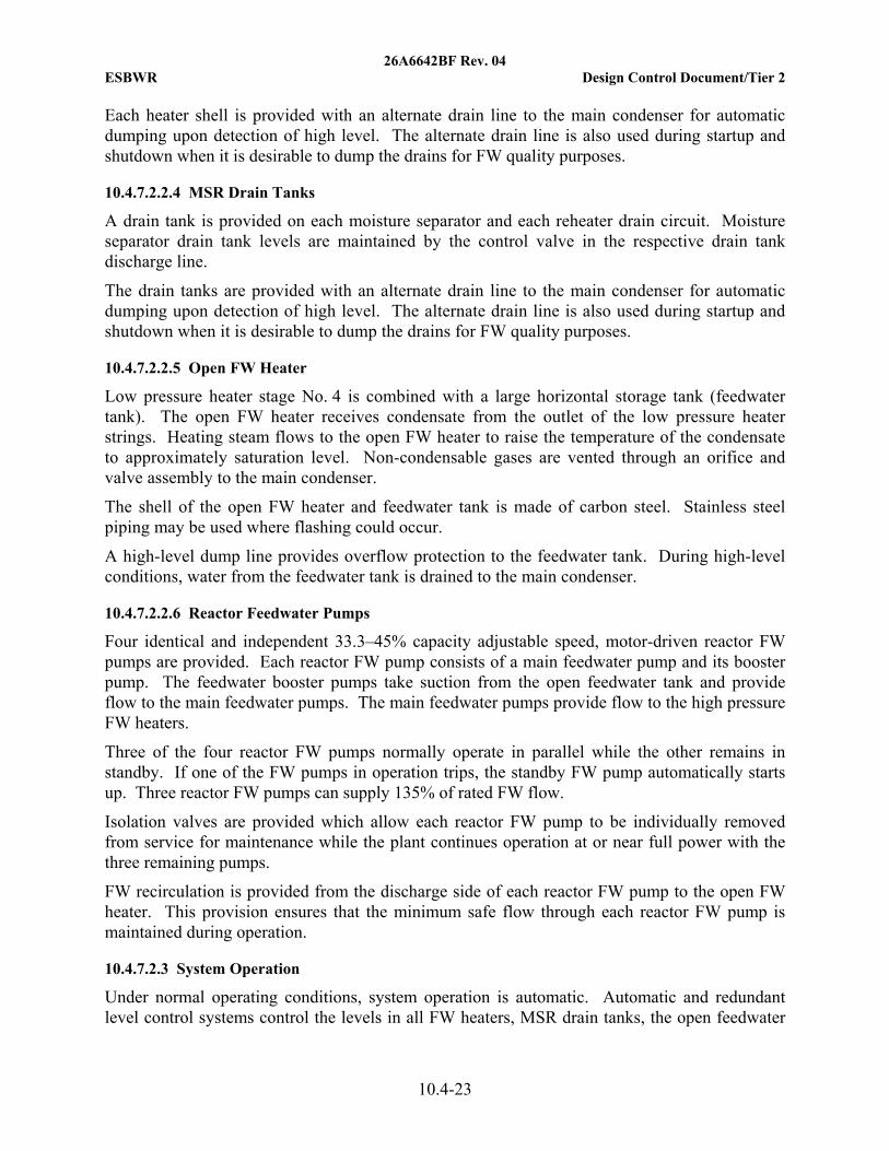
26A6642BF Rev. 04 ESBWR Design Control Document/Tier 2
10.4-23
Each heater shell is provided with an alternate drain line to the main condenser for automatic dumping upon detection of high level. The alternate drain line is also used during startup and shutdown when it is desirable to dump the drains for FW quality purposes.
10.4.7.2.2.4 MSR Drain Tanks
A drain tank is provided on each moisture separator and each reheater drain circuit. Moisture separator drain tank levels are maintained by the control valve in the respective drain tank discharge line.
The drain tanks are provided with an alternate drain line to the main condenser for automatic dumping upon detection of high level. The alternate drain line is also used during startup and shutdown when it is desirable to dump the drains for FW quality purposes.
10.4.7.2.2.5 Open FW Heater
Low pressure heater stage No. 4 is combined with a large horizontal storage tank (feedwater tank). The open FW heater receives condensate from the outlet of the low pressure heater strings. Heating steam flows to the open FW heater to raise the temperature of the condensate to approximately saturation level. Non-condensable gases are vented through an orifice and valve assembly to the main condenser.
The shell of the open FW heater and feedwater tank is made of carbon steel. Stainless steel piping may be used where flashing could occur.
A high-level dump line provides overflow protection to the feedwater tank. During high-level conditions, water from the feedwater tank is drained to the main condenser.
10.4.7.2.2.6 Reactor Feedwater Pumps
Four identical and independent 33.3–45% capacity adjustable speed, motor-driven reactor FW pumps are provided. Each reactor FW pump consists of a main feedwater pump and its booster pump. The feedwater booster pumps take suction from the open feedwater tank and provide flow to the main feedwater pumps. The main feedwater pumps provide flow to the high pressure FW heaters.
Three of the four reactor FW pumps normally operate in parallel while the other remains in standby. If one of the FW pumps in operation trips, the standby FW pump automatically starts up. Three reactor FW pumps can supply 135% of rated FW flow.
Isolation valves are provided which allow each reactor FW pump to be individually removed from service for maintenance while the plant continues operation at or near full power with the three remaining pumps.
FW recirculation is provided from the discharge side of each reactor FW pump to the open FW heater. This provision ensures that the minimum safe flow through each reactor FW pump is maintained during operation.
10.4.7.2.3 System Operation
Under normal operating conditions, system operation is automatic. Automatic and redundant level control systems control the levels in all FW heaters, MSR drain tanks, the open feedwater

26A6642BF Rev. 04 ESBWR Design Control Document/Tier 2
10.4-24
heater and the condenser hotwells. Feedwater heater levels are controlled by modulating drain valves. Control valves at the discharge of the LP feedwater heaters control the level in the feedwater tank. Valves in the makeup line to the condenser from the condensate storage tank and in the return line to the condensate storage tank control the level in the condenser hotwells.
During power operation, FW flow is automatically controlled by the reactor FW pump speed that is set by the speed control system. The control system can utilize measurements of steam flow, FW flow, and reactor level to regulate the FW pump speed.
During startup and shutdown, FW flow is automatically regulated by the low flow control valve. The low flow control valve can also regulate flow from a condensate pump to the reactor vessel for initial fill and cleanup. Control valves at the discharge of the LP heaters regulate condensate flow to control the feedwater tank level and to isolate flow to the storage tank when the low flow control valve is used to by-pass the feedwater pumps and storage tank during direct condensate flow to the reactor vessel. Provisions are included in C&FS operating procedures to minimize Feedwater nozzle cracking during periods of low Feedwater flow.
Feedwater heater No. 7 can be used to control reactor power during startup and power maneuvers by controlling final feedwater temperature. The feedwater temperature operating domain is discussed in Subsection 4.4.4.3.
The C&FS has sufficient capacity and control stability to accommodate normally anticipated step and ramp changes in reactor power. In conjunction with the Turbine Bypass System, the system is capable of accepting a full generator load rejection without reactor trip and without the operation of reactor safety relief valves.
10.4.7.3 Evaluation
The C&FS does not serve or support any safety-related function. Systems analyses show that failure of this system cannot compromise any safety-related system/function or prevent safe shutdown. C&FS component failure analysis results are provided in Table 10.4-6.
During operation, radioactive steam and condensate are present in the FW heating portion of the system, which includes the extraction steam piping, FW heater shells, heater drain piping, and heater vent piping. Shielding and access control are provided as necessary (see Chapter 12). The C&FS is designed to minimize leakage with welded construction utilized where practicable. Relief valve discharges and operating vents are channeled through closed systems.
If it is necessary to remove a component from service such as a FW heater, pump, or control valve, continued operation of the system is possible by use of the multi-string arrangement and the provisions for isolating and bypassing selected equipment and sections of the system.
The majority of the condensate and FW piping considered in this section is located within the nonsafety-related Turbine Building. The portion that connects to the seismic interface restraint outside the containment is located in the steam tunnel between the Turbine and Reactor Buildings. This portion of the piping is analyzed for dynamic effects from postulated seismic events.
The FW control system is designed to ensure that there could not be large sudden changes in FW flow that could induce water hammer. The design of the ESBWR C&FS complies with NUREG–0927, Rev. 1, “Evaluation of Water Hammer Occurrence in Nuclear Power Plants.” In
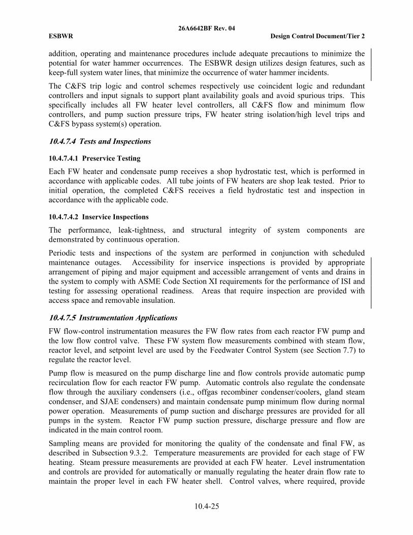
26A6642BF Rev. 04 ESBWR Design Control Document/Tier 2
10.4-25
addition, operating and maintenance procedures include adequate precautions to minimize the potential for water hammer occurrences. The ESBWR design utilizes design features, such as keep-full system water lines, that minimize the occurrence of water hammer incidents.
The C&FS trip logic and control schemes respectively use coincident logic and redundant controllers and input signals to support plant availability goals and avoid spurious trips. This specifically includes all FW heater level controllers, all C&FS flow and minimum flow controllers, and pump suction pressure trips, FW heater string isolation/high level trips and C&FS bypass system(s) operation.
10.4.7.4 Tests and Inspections
10.4.7.4.1 Preservice Testing
Each FW heater and condensate pump receives a shop hydrostatic test, which is performed in accordance with applicable codes. All tube joints of FW heaters are shop leak tested. Prior to initial operation, the completed C&FS receives a field hydrostatic test and inspection in accordance with the applicable code.
10.4.7.4.2 Inservice Inspections
The performance, leak-tightness, and structural integrity of system components are demonstrated by continuous operation.
Periodic tests and inspections of the system are performed in conjunction with scheduled maintenance outages. Accessibility for inservice inspections is provided by appropriate arrangement of piping and major equipment and accessible arrangement of vents and drains in the system to comply with ASME Code Section XI requirements for the performance of ISI and testing for assessing operational readiness. Areas that require inspection are provided with access space and removable insulation.
10.4.7.5 Instrumentation Applications
FW flow-control instrumentation measures the FW flow rates from each reactor FW pump and the low flow control valve. These FW system flow measurements combined with steam flow, reactor level, and setpoint level are used by the Feedwater Control System (see Section 7.7) to regulate the reactor level.
Pump flow is measured on the pump discharge line and flow controls provide automatic pump recirculation flow for each reactor FW pump. Automatic controls also regulate the condensate flow through the auxiliary condensers (i.e., offgas recombiner condenser/coolers, gland steam condenser, and SJAE condensers) and maintain condensate pump minimum flow during normal power operation. Measurements of pump suction and discharge pressures are provided for all pumps in the system. Reactor FW pump suction pressure, discharge pressure and flow are indicated in the main control room.
Sampling means are provided for monitoring the quality of the condensate and final FW, as described in Subsection 9.3.2. Temperature measurements are provided for each stage of FW heating. Steam pressure measurements are provided at each FW heater. Level instrumentation and controls are provided for automatically or manually regulating the heater drain flow rate to maintain the proper level in each FW heater shell. Control valves, where required, provide

26A6642BF Rev. 04 ESBWR Design Control Document/Tier 2
10.4-26
automatic discharge of heater drains to the condenser on detection of high level in the heater shell.
The total water volume in the C&FS is maintained through automatic makeup and rejection of condensate to the condensate storage tank. The system makeup and rejection are controlled by the redundant condenser hotwell level controllers.
10.4.8 Steam Generator Blowdown System (PWR)
Not applicable to the ESBWR.
10.4.9 Auxiliary Feedwater System (PWR)
Not applicable to the ESBWR.
10.4.10 COL Information
10.4-1-A Leakage (of Circulating Water Into the Condenser)
The COL Applicant will provide threshold values and recommended operator actions for chemistry excursions in the condensate system (Subsection 10.4.6.3).
10.4.11 References 10.4-1 Standards for Steam Surface Condensers, Heat Exchanger Institute.

26A6642BF Rev. 04 ESBWR Design Control Document/Tier 2
10.4-27
Table 10.4-1
Main Condenser Data
Parameter Standard Plant Value
Condenser Type Transversal, 3 shells, multipressure
Design duty, total 3 shells, MW (BTU/hr) 3057 (10.43x10⁹)
Shell pressures 30°C (86ºF) Circ. water, MPaA (psia)
0.0067 (0.98), 0.0089 (1.29), 0.012 (1.7)
Circulating water flow rate, m3/hr (gpm) ~152,000 (671,000)*
Tube side temperature rise-total 3 shells, °C (°F) 17.3° (31.2°)
Shell design pressure range, MPaA (psia) 0 to 0.35 (0 to 50.76)
Hotwell storage capacity-total 3 shells, m3 (ft3) 316 (11.2·103)
Channel design pressure range, MPaA (psia) 0 to 0.38 (0 to 55.1)
Surface Area, m2 (ft2) 1.5x10⁵ (1.61x10⁶)
Number of tube passes per shell 1
Applicable codes and standards HEI Standards for Steam Surface Condensers
Alarms and Trips:
High condenser pressure turbine alarm, MPaA (psia)
0.017 (2.5)
High condenser pressure turbine trip and reactor scram, MPaA (psia)
0.024-0.034 (3.4-4.9)
Main steam isolation valve closure, and Bypass valve closure, MPaA (psia)
0.068-0.078 (9.8-11.3)
* This is CIRC flow required for 100% turbine bypass following a turbine trip. This flow has not been analyzed
to support island mode under all conditions.

26A6642BF Rev. 04 ESBWR Design Control Document/Tier 2
10.4-28
Table 10.4-2
Main Condenser Evacuation System
Parameter Standard Plant Value
Steam Jet Air Ejector System:
Number of ejector stages per element 2
Number of intercondensers per set 2
Number of ejector sets and capacity 2 x 100%
Required supply steam pressure, MPaA (psia)
0.827 (120)
Normal steam supply source Cross-around
Start-up Vacuum Pump System:
Number of pumps and capacity 2 x 50% (minimum)

26A6642BF Rev. 04 ESBWR Design Control Document/Tier 2
10.4-29
Table 10.4-3
Circulating Water System
Parameter ESBWR Conceptual Design Value*
Circulating Water Pumps:
Number of pumps 4
Pump type Vertical, wet pit
Unit flow capacity**, m3/hr (gpm) Approx. 38300 (170000)
Driver Type Electric motor
Operating Temperatures:
Normal Power Heat Sink temperature range for water entering the CIRC, ºC (ºF)
0*** to 37.8 (32 to 100)
Temperature range of water delivered to the main condenser, ºC (ºF)
5*** to 37.8 (41 to 100)
CIRC temperature for rated turbine performance, ºC (ºF)
30° (86°)
Maximum CIRC temperature for 100% turbine bypass capability, ºC (ºF)
35.6° (96°)****
* Number of pumps and pump flow are site dependent. Values provided above are for ESBWR CIRC System
conceptual design. ** This capacity is for condenser cooling requirements only; see Table 9.2-2 for potential additional capacity
requirements for Plant Service Water. *** If the Normal Power Heat Sink does not have the capability to control the minimum temperature, the
minimum temperature would be maintained by warm water recirculation. **** Maximum temperature is based on 81ºF wet bulb temperature (2% exceedence) and a typical 15ºF approach
temperature for natural draft cooling towers (see Table 2.0-1).

26A6642BF Rev. 04 ESBWR Design Control Document/Tier 2
10.4-30
Table 10.4-4
Condensate Purification System
Parameter Standard Plant Value
Condensate Filters:
Filter type High efficiency
Number of vessels 6
Total design flow rate, m3/hr (gpm) 6480 (28530)
Condensate Demineralizers:
Demineralizer type Mixed bed ion exchanger
Number of vessels 8
Total design flow rate, m3/hr (gpm) 6480 (28530)
Specific flow rate, l/s/m2 (gal/s/ft2) < 27.2 (<0.67)
Other System Features:
Filter backwash tank 1
Resin receiver tank 2
Resin storage tank 2
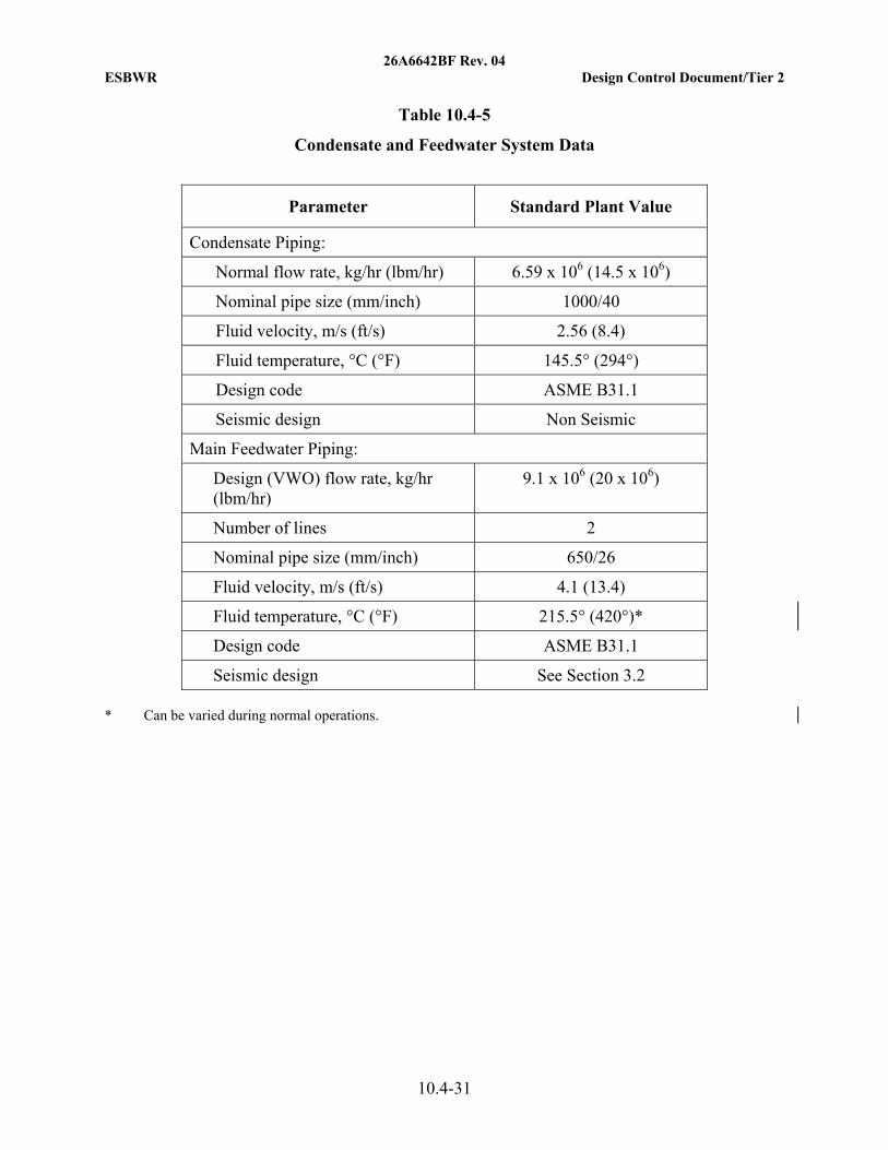
26A6642BF Rev. 04 ESBWR Design Control Document/Tier 2
10.4-31
Table 10.4-5
Condensate and Feedwater System Data
Parameter Standard Plant Value
Condensate Piping:
Normal flow rate, kg/hr (lbm/hr) 6.59 x 10⁶ (14.5 x 10⁶)
Nominal pipe size (mm/inch) 1000/40
Fluid velocity, m/s (ft/s) 2.56 (8.4)
Fluid temperature, °C (°F) 145.5° (294°)
Design code ASME B31.1
Seismic design Non Seismic
Main Feedwater Piping:
Design (VWO) flow rate, kg/hr (lbm/hr)
9.1 x 10⁶ (20 x 106)
Number of lines 2
Nominal pipe size (mm/inch) 650/26
Fluid velocity, m/s (ft/s) 4.1 (13.4)
Fluid temperature, °C (°F) 215.5° (420°)*
Design code ASME B31.1
Seismic design See Section 3.2 * Can be varied during normal operations.

26A6642BF Rev. 04 ESBWR Design Control Document/Tier 2
10.4-32
Table 10.4-6
Condensate and Feedwater System Component Failure Analysis
Component Failure Effect on Train
Failure Effect on System Failure Effect on NBS
Condensate pump
None. Condenser hotwells and condensate pumps are interconnected.
None. Operation continues at full capacity, by automatic start up of the standby pump. The feedwater tank absorbs the flow transient.
None
No.1, 2, or 3 FW heater
One train of No. 1, 2, and 3 heaters is shut down. Remaining trains continue to operate.
Operation continues at reduced capacity, using parallel FW heaters. Load must not exceed turbine vendor’s requirements to protect the LP turbines from excessive steam flow.
Reactor control system is used to reduce reactor power to a level compatible to the safe LP turbine operation.
MSR drain tanks Drains from affected drain subsystem are dumped to condenser.
100% of the corresponding drains are dumped to condenser.
None. The drain systems are designed to permit operation with normal full reactor power, FW temperature, and flow rate.
Reactor FW pump
None. Feedwater pumps are interconnected.
None. Operations may continue at full capacity by automatic start up of the standby pump
None.
FW open heater Open heater overflow caused by condensate control valve failure.
None. There is an evacuation line to Main Condenser.
None.

26A6642BF Rev. 04 ESBWR Design Control Document/Tier 2
10.4-33
Table 10.4-6
Condensate and Feedwater System Component Failure Analysis
Component Failure Effect on Train
Failure Effect on System Failure Effect on NBS
Low flow control valve
None. Not train dependent.
None. The low flow control valve is used up to 15% power. The low flow control valve is provided with a capacity (Cv) that supports up to 20% to ensure control at 15%.
Full power: None. Low Power (<15%): Bypass system accepts excess steam flow until the reactor control system reduces power to an acceptable level.
No. 5, 6, or 7 FW heater.
One train is shut down.
C&FS operation continues at capacity, using parallel train and bypass line.
Reactor control system is used to adjust the reactor power to permit continued operation with the reduced FW temperature. Power maneuvering capability using the No.7 FW heaters is reduced.

26A6642BF Rev. 04 ESBWR Design Control Document/Tier 2
10.4-34
Figure 10.4-1. Circulating Water System

26A6642BF Rev. 04 ESBWR Design Control Document/Tier 2
10.4-35
Figure 10.4-2. Main Condenser Evacuation System

26A6642BF Rev. 04 ESBWR Design Control Document/Tier 2
10.4-36
Figure 10.4-3. Turbine Gland Seal System

26A6642BF Rev. 04 ESBWR Design Control Document/Tier 2
10.4-37
Figure 10.4-4. Signal Flow Chart for Turbine Bypass Control Unit
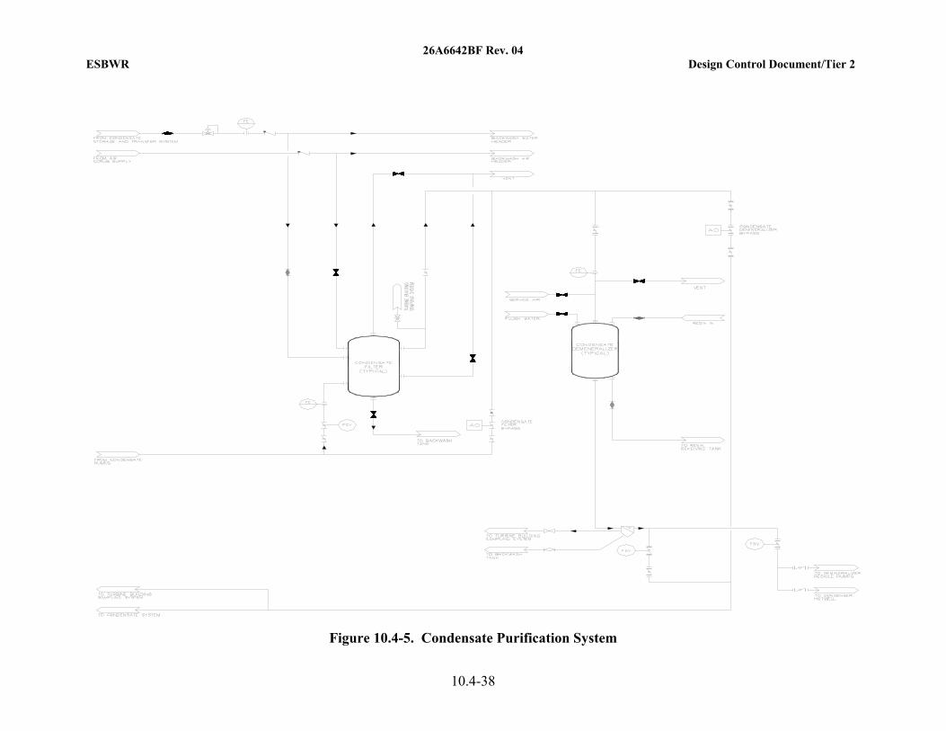
26A6642BF Rev. 04 ESBWR Design Control Document/Tier 2
10.4-38
Figure 10.4-5. Condensate Purification System

26A6642BF Rev. 04 ESBWR Design Control Document/Tier 2
10.4-39
Figure 10.4-6a. LP Extraction Steam System

26A6642BF Rev. 04 ESBWR Design Control Document/Tier 2
10.4-40
Figure 10.4-6b. LP Drain and Vent System

26A6642BF Rev. 04 ESBWR Design Control Document/Tier 2
10.4-41
Figure 10.4-7a. HP Extraction Steam System
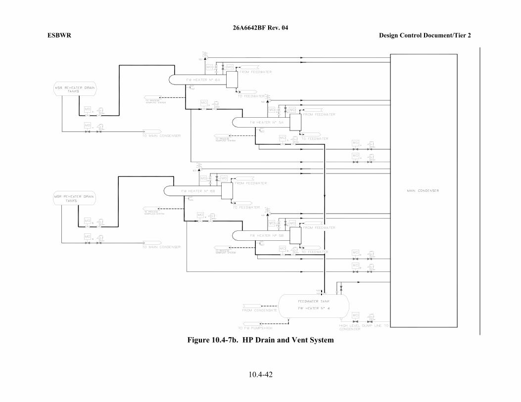
26A6642BF Rev. 04 ESBWR Design Control Document/Tier 2
10.4-42
Figure 10.4-7b. HP Drain and Vent System

26A6642BF Rev. 04 ESBWR Design Control Document/Tier 2
10A-1


