11
ESC 100 – Exploring Engineering Lab 1 – Introduction to Arduino Thursday, September 12, 2013

ESC 100 – Exploring Engineering
Lab 1 – Introduction to Arduino
Thursday, September 12, 2013

A bit more about me…
B.S. in Biomedical Engineering, Johns Hopkins University (May 2007)
Ph.D. in Bioengineering, University of Pennsylvania (August 2012)Thesis: Engineering Hyaluronic Acid Hydrogel Degradation to
Control Cellular Interactions and Adult Stem Cell Fate in 3D
Visiting Assistant Professor, Union College Bioengineering (September 2012 – present)
Sameer Sudhir
Max the pit-boxer dog(also an office dog)
Course update• All lab specific documents will be posted on my
website:– orzo.union.edu/~khetans– My office hours: TW 2-4pm, Butterfield 109
• Agenda for today:– Hand-in:
• Honor code affirmation• Clicker agreement• Pre-engineering survey (will do at start of lab)
– Arduino and PC/Mac setup– Introduction to Arduino
• Deliverables– Nothing to hand in at end of lab today!– Beginning of next lab: bring your working circuit 15 (LCD)
• Your grade will either be 100 (works) or 0 (doesn’t work)

RedBoard

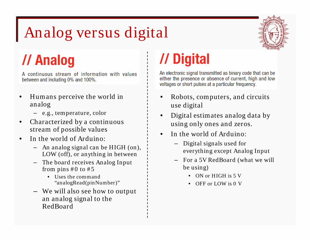
Analog versus digital
• Humans perceive the world in analog
– e.g., temperature, color• Characterized by a continuous
stream of possible values• In the world of Arduino:
– An analog signal can be HIGH (on), LOW (off), or anything in between
– The board receives Analog Input from pins #0 to #5
• Uses the command “analogRead(pinNumber)”
– We will also see how to output an analog signal to the RedBoard
• Robots, computers, and circuits use digital
• Digital estimates analog data by using only ones and zeros.
• In the world of Arduino:– Digital signals used for
everything except Analog Input– For a 5V RedBoard (what we will
be using)• ON or HIGH is 5 V• OFF or LOW is 0 V

Circuit 1 – LED
Let’s take a look at the code for this circuit

Returning to our earlier example...

This setup is equivalent to that on the previous slide!

Circuit 2 – Potentiometer
Let’s take a look at the code for this circuit
• In this two circuit setup, the signal going to the LED is dependent on the position of the potentiometer dial:

Wrapping up
• Try out these and the other circuits in your manual– The sooner you become familiar with Arduino, the
better shape you’ll be in for the project!
• Reminder: Working circuit #15 is due at the beginning of next class!
• Tomorrow lecture – Technical communication– Engineering seminars and HW– Intro to energy


