ControlDraw Demonstration A Safety Shutdown System Model Print and Review Report Thanks to Horizon Consulting for the original documents www.horizonconsultants.com Note - only selected portions of the model are in this PDF Project : Horizon Demo Model Cover Model: safetyLogic3.cnd Page: 1 of 38
Transcript
ControlDraw DemonstrationA Safety Shutdown System Model
Print and Review ReportThanks to Horizon Consulting for the original documents
www.horizonconsultants.comNote - only selected portions of the model are in this PDF
Project : Horizon Demo Model Cover
Model: safetyLogic3.cnd Page: 1 of 38
Table of Contents
Section PageCover 1Table of Contents 2Project Description 3Project Information 4Diagrams 5 1 - Plant Overview 5 2 - Boiler Overview 6 3 - Overall Cause and Effect Matrix 7 4 - Boiler Field startup panel 8 5 - Boiler Startup Sequence 9 6 - Effect FC-0159 10 9 - Effect XY-6367 XY-6369 11 12 - Effect XY-6375 12 13 - ESD01 12 14 - ESD02 13 15 - ESD03 13 16 - ESD04 14 17 - ESD05 14 18 - ESD06 15 19 - ESD07 15 20 - ESD08 16 21 - ESD09 16 22 - ESD10 17 23 - ESD11 17 24 - ESD12 18 25 - ESD13 19 26 - Alarm State Matrix. 20 27 - ESD1 Fault Tree 21 28 - Boiler Equipment Damage 22 29 - Original Cause and Effect 23 30 - SIL Results 24 31 - Original P&ID 25 32 - On Off Valve 26 32. . . Variant 2 - Closed LS 27 32. . . Variant 4 - No limit switches 28 33 - Analog Input from Transmitter 29 34 - Alarm Switch Input 30 35 - On/Off Effector 31 36 - Control Valve 32Data Reports: 33 Control System IO 33 Interlock Control Module 35 Measurement Analog 36 Measurement Switch 37Deleted Pages 38
Project : Horizon Demo Model Table of Contents
Model: safetyLogic3.cnd Page: 2 of 38
Burner Management System Design Model
Project : Horizon Demo Model Project Description
Model: safetyLogic3.cnd Page: 3 of 38
Project Information
Item Value
Project Name:Horizon Demo Model
Client: ControlDraw UsersReviewer View Name: ESDModel in e:\E\_CDReference\Samples3\Comments3.mdbLast edited with ControlDraw Version: 1141Printed with Reviewer Version: 482
View Contents
Project description wordsInformation PageDiagram Descriptions32 Diagrams6 Data ReportsDeleted Diagram List
Issue History
Date Issue Version Author Details
03/09/2008 Major Issue - 1A 221 Francis LoveringUpdated to latest ControlDraw capabilites
23/01/2005 Reissue 0A 98 Francis Lovering Preliminary for user comments.02/01/2005 Reissue 0A 53 Francis Lovering After Redrawing all pages02/01/2005 Reissue 0A 52 Francis Lovering
Project : Horizon Demo Model Diagram
Model: safetyLogic3.cnd Page: 4 of 38
Diagram 1 - Plant OverviewDiagram Version: 230 Class: Process Cell
NoteThese objects are linked to diagrams in the model, for reference. They also
prevent the pages being shown as orphaned in Model Review.They are class None and do nothing in the database.
Key to Cause and Effect objects
U36
Boiler overview graphic
Hardware Concept
Boiler StartupSequence
High Combustibles/ Explosions
Event Tree
Note
This model is under development. Please look at each diagram and especially the notes.(Use Ctrl_G to find all Note objects in the model)
Boiler EquipmentDamage
Event Tree
Original Cause andEffect
SIL Results
IO List connected tomodel
This is the top of theProcedural heirachy
This is the top level ofthe physical heirachy
Note
At the top a simplified P&ID showing Cause and Effect objectsAll physical object data is rooted from this symbol
Note
Event Trees, with links to the ESD Functions
Child Page NumberContains the number of the page linked to a symbol.Click the number, or double click a symbol to open the page.
Note
Procedural Model Root ObjectAll procedural object data is rooted from this symbol
ESD1 Fault Tree
Note
This diagram is scripted to generate the probabilities from the tree.
Original ESD1 FaultTree
Effect Tags
ESD Effect with link to logic that drives the outputs in response to causes
ESD Cause with link to detection logic that generates the boolean flags for each possible cause
ESD000
Note
This model covers a Safety Shutdown system only. It would be possible to also include the DCS, with some development of classes to distinguish the ESD and DCS functions and hardware.
U36 Cause andEffect matrix
Alarm Enabling
Original P&ID
2
39
5
38
28
29
30
40
27 37
7
24
3
26
31
Project : Horizon Demo Model Diagram
Model: safetyLogic3.cnd Page: 5 of 38
Diagram 2 - Boiler OverviewDiagram Version: 224 Class: Unit
ESD01
UX6035
XY6367XY6369
UY6056
FC0159
ESD02
XY6364XY6366
UX6357
UX6358
XY6365
UX6359
XY6370
XL0216-R
XY6375
XL0216-S
XY6373
ESD10
ESD05
ESD06
ESD08
ESD09
LSLL6046
LT0106
AHH
LT0134
AHH
PT0130
BS0138
BS0137
HS6116
PT6045
PT6360
FT0156
PT0139
PT0135
F.D. Fan Lube Oil Pressure Transmitter
PT0211
XV6367 XV6369
FV0159
XV6366XV6364
XV6365
XV6370
XX6375 XX6373
Steam Drum
Mud Drum
Natural Gas
RefineryGas
Vent
PSL0178
Boiler Field startup panel
Alarms to DCS
LSL0131
LSH0131
ESD03
Economiser
ESD04
Control Room BSD ButtonHS
ESD11
Fan
ESD12
ESD13
ESD07
Note
This diagram could be simplified by sub division into equipment modules, however as the process is fairly simple this has not been done.
Overall Cause andEffect Matrix
Top Burner
HS0216/blnOut1Diagram 4
{28}
{28}
{38}
{38}
{38}
{38}
{38}
{38}
{38}
{28} {28}
13
35
35
14
35 35 35
35 35
17
18
20
21
34
33 33
33
34
34
34
33 33
33
33
33
33
32/2 32/2
36
32/2 32/2
32
32/4
35 35
34
4
34
34
9
6
7
8
10
12
11
15
16
22
34
23
24 25
19
3
Project : Horizon Demo Model Diagram
Model: safetyLogic3.cnd Page: 6 of 38
Diagram 3 - Overall Cause and Effect MatrixDiagram Version: 228 Class: Logic Function
DescriptionLow Low Steam Drum LevelHigh High Steam Drum PressureLoss of FlameLow Low Fuel Header Gas PressureLow Low Fuel Burner Gas PressureHigh High Fuel Burner Gas PressureLow Low Combustion Air FlowLow Low Pilot Gas Header PressureHigh High Furnace PressureBSD ButtonControl Room BSD ButtonLow Lube Oil PressureLow Low Lube Oil Pressure
OutputMain Fuel Gas Control ValveMain Fuel Gas Control ValvePilot Gas Shutdown ValvesPilot GasVentValveMain Fuel Gas Shutdown ValvesOxygen Analyzer DeEnergizedFan Interposing RelayLube Oil Aux. Pump Interposing Relay
EffectX5%ClosedOpenClosedDe-EnergiseStopStart
Logic page66789101112
TagnameFC0159XY6365XY6367 XY6369
XY6370XY6373XY6375
DescriptionMain Fuel Gas Control ValvePilot GasVentValveMain Fuel Gas Shutdown ValvesMain Fuel Gas Shutdown ValvesOxygen Analyzer DeEnergizedFan Interposing RelayLube Oil Aux. Pump Interposing Relay
TagFV0159XV6365XV6367XV6369XV6370XX6373XX6375
Connects toMain Fuel Gas Control ValvePilot Gas Vent ValveMain Fuel Gas Shutdown ValveMain Fuel Gas Shutdown ValveOxygen AnalyzerFD Fan Interposing RelayLube Oil Aux. Pump Interposing RE
S 2 Verify PurgeOperator to open Air Dampers to Purge position
S 3 Permissives
T 3 Verify PurgeFT0156.AI = Off
NoteThis diagram is under development. The Flowchart is not complete, but at present shows how the model can represent the flowchart using Special '_SetSymbols' objects. These link the text in the steps to the obects in the model. This ensures that object references are correct, and that tagname changes propagate.The Flowchart has been converted to a Sequential Function Chart.
Startup Sequence.pdf
(Source files reference object)The flowchart is an image from the Horizon Visio-Boiler StartupSequence.pdf file. It will be deleted, leaving just this document
reference when the sequence in the model is appproved.
Review Status:Under Development
Note
ReviewStatus special object - shows the development status of the diagram as set in page details.
Note
_SetSymbols special objects - show a list of settings for objects in the model
S 4
T 5
PT6360.AHH = OffPT6045.ALL = OffPT0130.AHH = OffESD01 Active = False
S 5
T 6
S 6
T 7
T 4 Permissives
XV6364.ZSC = True 'Pilot Gas Block Valves ClosedXV6366.ZSC = TrueXV6367.ZSC = True 'Fuel Gas Block Valves ClosedXV6369.ZSC = TrueBS0137.blnVal = True 'Flame Not present
Project : Horizon Demo Model Diagram
Model: safetyLogic3.cnd Page: 9 of 38
Diagram 6 - Effect FC-0159Diagram Version: 230 Class: Control Module
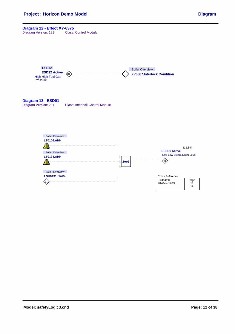
Diagram 12 - Effect XY-6375Diagram Version: 181 Class: Control Module
ESD12 Active
High High Fuel Gas Pressure
ESD12
XV6367.Interlock Condition
Boiler Overview
Diagram 13 - ESD01Diagram Version: 201 Class: Interlock Control Module
2oo3
ESD01 Active
Low Low Steam Drum Level
LT0106.AHH
Boiler Overview
LSH0131.blnVal
Boiler Overview
LT0134.AHH
Boiler Overview
Cross Reference
TagnameESD01 Active
Page1114
{11,14}
Project : Horizon Demo Model Diagram
Model: safetyLogic3.cnd Page: 12 of 38
Diagram 14 - ESD02Diagram Version: 179 Class: Interlock Control Module
ESD02 Active
High High Steam Drum PressurePT0130.AHH
Boiler Overview
Cross Reference
TagnameESD02 Active
Page69
{6,9}
Diagram 15 - ESD03Diagram Version: 179 Class: Interlock Control Module
BS0137.blnVal
Boiler Overview
BS0138.blnVal
Boiler Overview
ESD03 Active
Loss of Flame
Cross ReferenceTagnameESD03 Active
Page69
{6,9}
Project : Horizon Demo Model Diagram
Model: safetyLogic3.cnd Page: 13 of 38
Diagram 16 - ESD04Diagram Version: 179 Class: Interlock Control Module
ESD04 Active
Low Low Fuel HeaderGas PressurePT6045.ALL
Boiler Overview
Cross Reference
TagnameESD04 Active
Page69
{6,9}
Diagram 17 - ESD05Diagram Version: 179 Class: Interlock Control Module
ESD05 Active
Low Low Fuel Gas PressurePT6360.AHH
Boiler Overview
Cross ReferenceTagnameESD05 Active
Page69
{6,9}
Project : Horizon Demo Model Diagram
Model: safetyLogic3.cnd Page: 14 of 38
Diagram 18 - ESD06Diagram Version: 179 Class: Interlock Control Module
ESD06 Active
High High Fuel Gas PressurePT6360.ALL
Boiler Overview
Cross ReferenceTagnameESD06 Active
Page69
{6,9}
Diagram 19 - ESD07Diagram Version: 179 Class: Interlock Control Module
ESD07 Active
Low Low Fuel Gas PressureFT0156.ALL
Boiler Overview
Cross Reference
TagnameESD07 Active
Page69
{6,9}
Project : Horizon Demo Model Diagram
Model: safetyLogic3.cnd Page: 15 of 38
Diagram 20 - ESD08Diagram Version: 179 Class: Interlock Control Module
ESD08 Active
Low Low Fuel Gas PressurePT0139.ALL
Boiler Overview
Cross Reference
TagnameESD08 Active
Page69
{6,9}
Diagram 21 - ESD09Diagram Version: 179 Class: Interlock Control Module
ESD09 Active
High High Fuel Gas PressurePT0135.ALL
Boiler Overview
Cross Reference
TagnameESD09 Active
Page69
{6,9}
Project : Horizon Demo Model Diagram
Model: safetyLogic3.cnd Page: 16 of 38
Diagram 22 - ESD10Diagram Version: 96 Class: Interlock Control Module
ESD10 Active
BSD Button
Cross Reference
TagnameESD10 Active
Page710
{7,10}
Diagram 23 - ESD11Diagram Version: 179 Class: Interlock Control Module
HS.blnVal
Boiler Overview
ESD11 Active
Control Room BSD Button
Cross Reference
TagnameESD11 Active
Page69
{6,9}
Project : Horizon Demo Model Diagram
Model: safetyLogic3.cnd Page: 17 of 38
Diagram 24 - ESD12Diagram Version: 189 Class: Interlock Control Module
ESD12 Active
High High Fuel Gas PressurePT0135.AL
Boiler Overview
Cross Reference
TagnameESD12 Active
Page13
{13}
Project : Horizon Demo Model Diagram
Model: safetyLogic3.cnd Page: 18 of 38
Diagram 25 - ESD13Diagram Version: 179 Class: Interlock Control Module
ESD13 Active
High High Fuel Gas PressurePT0211.ALL
Boiler Overview
Cross Reference
TagnameESD13 Active
Page69
{6,9}
Project : Horizon Demo Model Diagram
Model: safetyLogic3.cnd Page: 19 of 38
Diagram 26 - Alarm State Matrix. Diagram Version: 230 Class: Logic Function
Alarm Enabling
FT0156.AH
FT0156.AHH
FT0156.AL
FT0156.ALL
LT0106.AH
LT0106.AHH
LT0106.AL
LT0106.ALL
LT0134.AH
LT0134.AHH
LT0134.AL
LT0134.ALL
PT0130.AH
PT0130.AHH
PT0130.AL
PT0130.ALL
PT0135.AH
PT0135.AHH
PT0135.AL
PT0135.ALL
PT0139.AH
PT0139.AHH
PT0139.AL
PT0139.ALL
PT0211.AH
PT0211.AHH
PT0211.AL
PT0211.ALL
PT6360.AH
PT6360.AHH
PT6360.AL
PT6360.ALL
PT6045.AH
PT6045.AHH
PT6045.AL
PT6045.ALL
Enabled
Disable
Disable
Disable
Disable
Disable
Disable
Disable
Disable
Disable
Disable
Disable
Disable
Disable
Disable
Disable
Disable
Disable
Disable
Disable
Disable
Disable
Disable
Disable
Disable
Disable
Disable
Disable
Disable
Disable
Disable
Disable
Disable
Disable
Disable
Disable
Enabled
Disable
Disable
Disable
Disable
Disable
Disable
Disable
Disable
Disable
Disable
Disable
Enable
Enable
Enable
Enable
Enable
Enable
Disable
Disable
Disable
Disable
Disable
Disable
Disable
Disable
Disable
Disable
Disable
Disable
Disable
Disable
Disable
Disable
Disable
Disable
Enable
Enable
Enable
Enable
Enable
Enable
Enable
Enable
Enable
Enable
Enable
Enable
Enable
Enable
Enable
Enable
Enable
Enable
Enable
Enable
Enable
Enable
Enable
Enable
Enable
Enable
Enable
Enable
Enable
Enable
Enable
Enable
Enable
Enable
Enable
Enable
Enable
Enable
Enable
Enable
Enable
Enable
Enable
Enable
Enable
Enable
Enable
Enable
Enable
Enable
Enable
Enable
Enable
Enable
Enable
Enable
Enable
Enable
Enable
Enable
Enable
Enable
Enable
Enable
Enable
Enable
Enable
Enable
Enable
Enable
Enable
Enable
Enable
Enable
Enable
Enable
Enable
Enable
Enable
Enable
Enable
Enable
Enable
Enable
Enable
Enable
Enable
Enable
Enable
Enable
Enable
Enable
Enable
Enable
Enable
Enable
Enable
Enable
Enable
Enable
Enable
Enable
Enable
Enable
Enable
Enable
Enable
Enable
Enable
Enable
Enable
Enable
Enable
Enable
Enable
Enable
Enable
Disable
Enable
Enable
Enable
Enable
Enable
Enable
Enable
Enable
Disable
Enable
Enable
Enable
Enable
Enable
Enable
Enable
Enable
Enable
Enable
Enable
Enable
Enable
Enable
Enable
Enable
Enable
S 1 Start FDFan
S 2 VerifyPurge
S 3Permissives S 4 S 5 S 6
Alarm State Matrix
Using a state model provides a highly efficient way to define the enabling of alarms. The safety system, as a complete entity is defined in terms of possible states, a method that vastly reduces the number of states that have to be considered. Then each possible alarm can be considered for it relevance in each state, producing an Alarm State Matrix. In this case the states correspond with operating sequence stepsThis is not yet correct, But shows how it can be done!
EventLow Steam Drum Water LevelFuel Gas ValvesFuel Gas Valves 1Fuel Gas Valves 2Level measurentsXV6367XY6367XY6369XV6369LT0106LT0134LSLL6046XV-CCLT-CCSOV-CCTMR
This diagram is scripted to generate the probabilities from the tree. It does not use the recursive logic that systems such as Safire deploys (although this is a possible development - ControlDraw is full of recursive functions)Instead simple formulae are used for each 'gate'. And's produce the product of the inputs, Or's Add them. This is programmed into the object dynamics.
Note Safire Links!
Developments could link this Model to the Safire model, if Safire is to be retained.
Note F9
F9 - Put into Run mode to evaluate the logic
EventLow Steam Drum Water LevelFuel Gas ValvesFuel Gas Valves 1Fuel Gas Valves 2Level measurentsXV6367XY6367XY6369XV6369LT0106LT0134LSLL6046XV-CCLT-CCSOV-CCTMR
This diagram is shows how an Event Tree can be drawn and linked to the relevant diagrams. The links are jumps because the diagram is informative rather than being data generating. An alternative structure could be used where this type of diagram is actually a data generating parent however at present this model is not structured that way.
Low Low Steam Drum LevelESD01
Boiler Overview
ESD02
Boiler Overview
Low Lube Oil PressureESD12
Boiler Overview
Low Low Lube Oil PressureESD13
Boiler Overview 13 14
24
25
Project : Horizon Demo Model Diagram
Model: safetyLogic3.cnd Page: 22 of 38
Diagram 29 - Original Cause and EffectDiagram Version: 172 Class: None
Note
Here the original Cause and Effect chart has been pasted in as a picture.ControlDraw does Cause and Effect charts via a collection of objects and links and a matrix, as shown on the Cause and Effect diagram
3
Project : Horizon Demo Model Diagram
Model: safetyLogic3.cnd Page: 23 of 38
Diagram 30 - SIL ResultsDiagram Version: 209 Class: None
UsertextLow Low Steam Drum LevelHigh High Steam Drum PressureLoss of FlameLow Low Fuel Header Gas PressureLow Low Fuel Burner Gas PressureHigh High Fuel Burner Gas PressureLow Low Combustion Air FlowLow Low Pilot Gas Header PressureHigh High Furnace PressureBSD ButtonControl Room BSD ButtonLow Lube Oil PressureLow Low Lube Oil Pressure
Imported from Horizon data
Project : Horizon Demo Model Diagram
Model: safetyLogic3.cnd Page: 24 of 38
Diagram 31 - Original P&IDDiagram Version: 219 Class: None
Included forreference only
Project : Horizon Demo Model Diagram
Model: safetyLogic3.cnd Page: 25 of 38
Diagram 32 - On Off ValveDiagram Version: 201 RefVers: 1631 Class: Valve
PCSNodeInst: TextDefault: !Inherit
ESDInst: Boolean
TMRCInst: SingleDefault: 2
TestedTest Sheet Table
Test object FieldObj: Text
TMROInst: SingleDefault: 5
TypeInst: Text
A/MAuto/Manual0 = manual, 1 = AutoSet by Unit Manual
AutoCmdAuto Command From control logic
MANManual Command0 = close, 1 = OpenOperator set
Valve Driver
Standard Auto/Manual.
Travel is timed in each direction, depending on Limits switches. Timeout causes Fail to Open or Fail to Close Alarm.Individual times for each direction must be provided.
FTO
Fail to Open Alarm
FTC
Fail to Close Alarm
TMRCMaximum Close Travel Time
DOSovDIClosed
DIOpen
Interlock Condition
OVROOverride Open = If set to 1 the Open limit switch is ignored
OVRCOverride Closed - If set to 1 the Open limit switch is ignored
Set by parent EMAssociated with cm recorded events so as to make batch log include cm events.
FailOpenInst: Boolean
SignedTest Sheet Table
{10,13}
Project : Horizon Demo Model Diagram
Model: safetyLogic3.cnd Page: 26 of 38
Diagram 32 - On Off ValveDiagram Version: 201 RefVers: 1631 Class: Valve
Variant 2 - Closed LS
PCSNodeInst: TextDefault: !Inherit
ESDInst: Boolean
TMRCInst: SingleDefault: 2
TestedTest Sheet Table
Test object FieldObj: Text
TMROInst: SingleDefault: 5
TypeInst: Text
A/MAuto/Manual0 = manual, 1 = AutoSet by Unit Manual
AutoCmdAuto Command From control logic
MANManual Command0 = close, 1 = OpenOperator set
Valve Driver
Standard Auto/Manual.
Travel is timed in each direction, depending on Limits switches. Timeout causes Fail to Open or Fail to Close Alarm.Individual times for each direction must be provided.
FTC
Fail to Close Alarm
TMR
Maximum Close Travel Time
DOSovDIClosed
Interlock Condition
OVR
Override Closed - If set to 1 the Open limit switch is ignored
Set by parent EMAssociated with cm recorded events so as to make batch log include cm events.
FailOpenInst: Boolean
SignedTest Sheet Table
{10,13}
Project : Horizon Demo Model Diagram
Model: safetyLogic3.cnd Page: 27 of 38
Diagram 32 - On Off ValveDiagram Version: 201 RefVers: 1631 Class: Valve
Variant 4 - No limit switches
PCSNodeInst: TextDefault: !Inherit
ESDInst: Boolean
TMRCInst: SingleDefault: 2
TestedTest Sheet Table
Test object FieldObj: Text
TMROInst: SingleDefault: 5
TypeInst: Text
A/MAuto/Manual0 = manual, 1 = AutoSet by Unit Manual
AutoCmdAuto Command From control logic
MANManual Command0 = close, 1 = OpenOperator set
Valve Driver
Standard Auto/Manual.
Travel is timed in each direction, depending on Limits switches. Timeout causes Fail to Open or Fail to Close Alarm.Individual times for each direction must be provided.