Journal of the Mechanics and Physics of Solids 52 (2004) 567 – 589 www.elsevier.com/locate/jmps Eshelby problem of polygonal inclusions in anisotropic piezoelectric full- and half-planes E. Pan ∗ Department of Civil Engineering, The University of Akron, Akron, OH 44325-3905, USA Received 9 January 2003; received in revised form 4 August 2003; accepted 4 August 2003 Abstract This paper presents an exact closed-form solution for the Eshelby problem of polygonal inclusion in anisotropic piezoelectric full- and half-planes. Based on the equivalent body-force concept of eigenstrain, the induced elastic and piezoelectric elds are rst expressed in terms of line integral on the boundary of the inclusion with the integrand being the Green’s function. Using the recently derived exact closed-form line-source Green’s function, the line integral is then carried out analytically, with the nal expression involving only elementary functions. The exact closed-form solution is applied to a square-shaped quantum wire within semiconductor GaAs full- and half-planes, with results clearly showing the importance of material orientation and piezoelectric coupling. While the elastic and piezoelectric elds within the square-shaped quantum wire could serve as benchmarks to other numerical methods, the exact closed-form solution should be useful to the analysis of nanoscale quantum-wire structures where large strain and electric elds could be induced by the mist strain. ? 2003 Elsevier Ltd. All rights reserved. Keywords: Electromechanical coupling; Anisotropic piezoelectric half-plane; Green’s function; Stroh form- alism; General surface boundary condition; Eshelby problem; Polygonal inclusion; Strained quantum wires 1. Introduction The Eshelby problem (Eshelby, 1957; Willis, 1981; Mura, 1987) is of great im- portance in various engineering and physical elds, and is the subject of extensive studies (Bacon et al., 1978; Mura, 1987; Ting, 1996; Buryachenko, 2001). Some of the recent studies include the eective elastoplastic behavior of composites (Ju and Sun, 2001), non-uniform Gaussian and exponential eigenstrain within ellipsoids (Sharma and ∗ Tel.: +1-330-972-6739; fax: +1-330-972-6020. E-mail address: [email protected](E. Pan). 0022-5096/$ - see front matter ? 2003 Elsevier Ltd. All rights reserved. doi:10.1016/S0022-5096(03)00120-0
Transcript
Journal of the Mechanics and Physics of Solids52 (2004) 567–589
www.elsevier.com/locate/jmps
Eshelby problem of polygonal inclusions inanisotropic piezoelectric full- and half-planes
E. Pan∗
Department of Civil Engineering, The University of Akron, Akron, OH 44325-3905, USA
Received 9 January 2003; received in revised form 4 August 2003; accepted 4 August 2003
Abstract
This paper presents an exact closed-form solution for the Eshelby problem of polygonalinclusion in anisotropic piezoelectric full- and half-planes. Based on the equivalent body-forceconcept of eigenstrain, the induced elastic and piezoelectric 4elds are 4rst expressed in termsof line integral on the boundary of the inclusion with the integrand being the Green’s function.Using the recently derived exact closed-form line-source Green’s function, the line integral isthen carried out analytically, with the 4nal expression involving only elementary functions. Theexact closed-form solution is applied to a square-shaped quantum wire within semiconductorGaAs full- and half-planes, with results clearly showing the importance of material orientationand piezoelectric coupling. While the elastic and piezoelectric 4elds within the square-shapedquantum wire could serve as benchmarks to other numerical methods, the exact closed-formsolution should be useful to the analysis of nanoscale quantum-wire structures where large strainand electric 4elds could be induced by the mis4t strain.? 2003 Elsevier Ltd. All rights reserved.
The Eshelby problem (Eshelby, 1957; Willis, 1981; Mura, 1987) is of great im-portance in various engineering and physical 4elds, and is the subject of extensivestudies (Bacon et al., 1978; Mura, 1987; Ting, 1996; Buryachenko, 2001). Some ofthe recent studies include the e<ective elastoplastic behavior of composites (Ju and Sun,2001), non-uniform Gaussian and exponential eigenstrain within ellipsoids (Sharma and
∗ Tel.: +1-330-972-6739; fax: +1-330-972-6020.E-mail address: [email protected] (E. Pan).
0022-5096/$ - see front matter ? 2003 Elsevier Ltd. All rights reserved.doi:10.1016/S0022-5096(03)00120-0
568 E. Pan / J. Mech. Phys. Solids 52 (2004) 567–589
Sharma, 2003), and dynamic Eshelby tensor in ellipsoidal inclusions (Michelitschet al., 2003). While most Eshelby problems associated with isotropic elasticity havebeen solved analytically for both two-dimensional (2D) and three-dimensional (3D) de-formations (i.e., Kouris and Mura, 1989; Downes et al., 1995; Faux et al., 1997; Glas,2001, 2002a,b; Rodin, 1996; Markensco<, 1993, 1998a,b; Nozaki and Taya, 2001;Yu and Sanday, 1991; Walpole, 1991; Rahman, 2001, 2002), those corresponding toanisotropic elasticity are usually solved numerically (see, e.g., Dong et al., 2003), withthe exception of transversely isotropic elasticity for which an analytical solution canbe derived (Rahman, 1999a,b; Withers, 1989; Yu et al., 1994).
In recent years, Eshelby problems with any shaped inclusion have been found tobe particularly useful in the study of strained semiconductor quantum devices wherethe strain-induced quantum dot (QD) and quantum wire (QWR) growth is crucialin semiconductor nanostructure design (see, e.g., Andreev et al., 1999; Davies, 1998;Davies and Larkin, 1994; Faux and Pearson, 2000; Faux et al., 1996, 1997; Freund,2000; Freund and Gosling, 1995; Gosling and Willis, 1995; Larkin et al., 1997; Parkand Chuang, 1998; Pearson and Faux, 2000). It is further noticed recently that piezo-electric coupling could have an important contribution to the electronic and opticalproperties of the semiconductor structure, due to the fact that most semiconductor ma-terials are piezoelectric, in particular, some of them are strongly electromechanicallycoupled (Pan, 2002a,b).
Owing to the complicated electromechanical coupling, however, only a few types ofEshelby problems have been solved so far for fully coupled piezoelectric solids. Theseinclude the ellipsoidal inclusion in transversely isotropic and piezoelectric 3D spaces(Wang, 1992; Dunn and Taya, 1993; Dunn and Wienecke, 1997; Koganet al., 1996) and elliptical inclusion in general anisotropic piezoelectric 2D planes(Ting, 1996; Chung and Ting, 1996; Lu and Williams, 1998; Ru, 1999, 2000; Wang andShen, 2003).
In spite of the importance of material anisotropy and electromechanical coupling innanoscale QWR semiconductor structures, analytical solutions were obtained only forisotropic elastic full- and half-planes if the QWR has an arbitrary shape (see, e.g.,Rodin, 1996; Downes et al., 1995; Faux et al., 1996, 1997; Nozaki and Taya, 1997;Nozaki et al., 2001; Kawashita and Nozaki, 2001; Glas, 2001, 2002a,b, 2003). Recently,however, Ru (1999, 2000) derived the solution due to an arbitrarily shaped inclusionin anisotropic full- and half-planes of elasticity and piezoelectricity using the specialconformal mapping method. While the mathematical approach of Ru (1999, 2000) iselegant, numerical implementation might not be a trivial task. It is also noticed thattruncation could be required if the conformal mapping function involves in4nite terms.Therefore, it is most desirable if an exact closed-form solution can be derived for thiscomplicated Eshelby problem.
In this paper, we thus present the exact closed-form solution for an arbitrarily shapedpolygonal inclusion in anisotropic piezoelectric full- and half-planes, with the half-planebeing under general surface conditions. We 4rst express the induced elastic and piezo-electric 4elds in terms of a line integral on the boundary of the inclusion based on theequivalent body-force concept of eigenstrain, with the integrand being the line-sourceGreen’s function. We then carry out the line integral analytically assuming that the
E. Pan / J. Mech. Phys. Solids 52 (2004) 567–589 569
inclusion is a polygon. The most remarkable feature is that the 4nal exact closed-formsolution involves only elementary functions, similar to the corresponding isotropic elas-tic solution (Faux et al., 1996, 1997; Nozaki and Taya, 1997; Glas, 2002a). Using thepresent simple solution, the elastic and piezoelectric 4elds due to multiple inclusionsor an array of QWRs can be easily obtained by adding all the QWRs’ contributionstogether. Furthermore, the solution to an elliptical inclusion can also be obtained byapproximating the curved boundary of the inclusion with piecewise straight-line seg-ments. As a numerical example, our solution is applied to a square-shaped quantumwire within GaAs full- and half-planes. The numerical results clearly show the impor-tance of material orientation and piezoelectric coupling. It is further observed that theboundary condition on the surface of the half-plane can also have a great e<ect onthe induced 4elds. Therefore, these results can serve as benchmarks and should be ofinterest to the analysis of nanoscale quantum-wire structures.
This paper is organized as follows: In Section 2, the equivalent body force of theeigenstrain is de4ned along with the governing equations. In Section 3, the boundaryintegral expression is obtained in terms of the line-source or point-source Green’sfunction. It is remarked that results in Sections 2 and 3 are applicable to both 2D and3D deformations. While in Section 4 the exact closed-form Green’s functions in bothfull- and half-planes are brieJy reviewed for the sake of easy reference, which includevarious surface boundary conditions, the exact closed-form expression for the inducedelastic and electric 4elds due to an inclusion of arbitrary polygon is derived in Section5. Numerical examples are presented in Section 6, and certain conclusions are drawnin Section 7.
2. Equivalent body force of eigenstrain
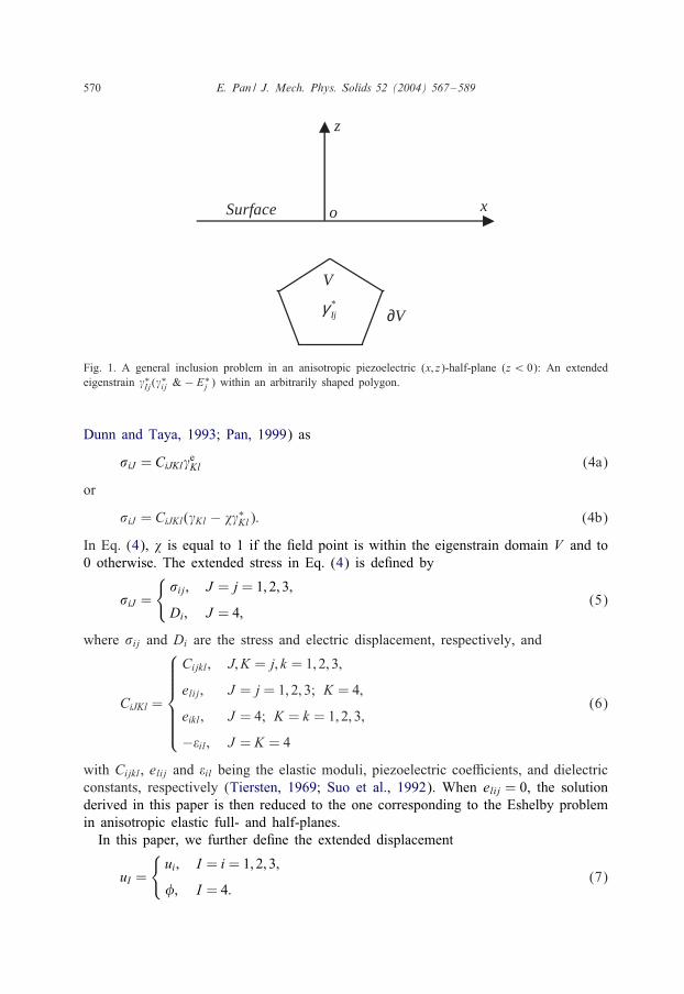
Let us assume that there is an extended general eigenstrain �∗Ij(�∗ij & − E∗
j ) withinthe domain V bounded by the surface @V (See Fig. 1 for 2D illustration). Our task isto 4nd the equivalent body force of this eigenstrain in V . To ease our discussion, we4rst de4ne the extended strain
�Ij =
{�ij; I = i = 1; 2; 3;
−Ej; I = 4;(1)
where �ij is the total elastic strain and Ej is the total electric 4eld, which are relatedto the total elastic displacement ui and the total electric potential as
�ij = 0:5(ui; j + uj; i);
Ej = −;j: (2)
It is further noted that the total extended strain can be written as
�Ij = �eIj + �∗Ij ; (3)
where �∗Ij is the extended eigenstrain in the inclusion (Fig. 1), and �eIj is the extended
strain that appears in the constitutive relation (Barnett and Lothe, 1975;
570 E. Pan / J. Mech. Phys. Solids 52 (2004) 567–589
x
z
Surface o
*Ijγ
V
∂V
Fig. 1. A general inclusion problem in an anisotropic piezoelectric (x; z)-half-plane (z ¡ 0): An extendedeigenstrain �∗Ij(�
∗ij & − E∗
j ) within an arbitrarily shaped polygon.
Dunn and Taya, 1993; Pan, 1999) as
�iJ = CiJKl�eKl (4a)
or
�iJ = CiJKl(�Kl − ��∗Kl): (4b)
In Eq. (4), � is equal to 1 if the 4eld point is within the eigenstrain domain V and to0 otherwise. The extended stress in Eq. (4) is de4ned by
�iJ =
{�ij; J = j = 1; 2; 3;
Di; J = 4;(5)
where �ij and Di are the stress and electric displacement, respectively, and
CiJKl =
Cijkl; J; K = j; k = 1; 2; 3;
elij ; J = j = 1; 2; 3; K = 4;
eikl; J = 4; K = k = 1; 2; 3;
−�il; J = K = 4
(6)
with Cijkl, elij and �il being the elastic moduli, piezoelectric coeMcients, and dielectricconstants, respectively (Tiersten, 1969; Suo et al., 1992). When elij = 0, the solutionderived in this paper is then reduced to the one corresponding to the Eshelby problemin anisotropic elastic full- and half-planes.
In this paper, we further de4ne the extended displacement
uI =
{ui; I = i = 1; 2; 3;
; I = 4:(7)
E. Pan / J. Mech. Phys. Solids 52 (2004) 567–589 571
For the eigenstrain problem, the equilibrium equation for the stresses and the balancefor the electric displacements are (Tiersten, 1969; Pan, 1999)
�iJ; i = 0 (8)
Now, for the extended eigenstrain �∗Ij in the inclusion V , substitution of Eq. (4b) intoEq. (8) gives
CiJKluK;li = CiJKl�∗Kl; i: (9)
It is clear that the right-hand side of Eq. (9) resembles the extended body force aswould appear on the left-hand side of Eq. (8), i.e.,
fJ = −CiJKl�∗Kl; i (10)
which is the equivalent body force of the eigenstrain. This concept is an extension ofthe purely elastic counterpart (Mura, 1987) to the piezoelectric solid. The equivalentbody force will be employed in the next section to 4nd the induced total extendeddisplacement uI and total extended strain �Ij.
3. Boundary integral expression in terms of Green’s function
For the extended general eigenstrain �∗Ij at x = (x; y; z) within the domain V , theinduced extended displacement at X = (X; Y; Z) can be found using the superpositionmethod. In other words, the response is an integral, over V , of the equivalent bodyforce de4ned by Eq. (10), multiplied by the point-source (line-source for 2D) Green’sfunction, i.e.,
uK (X) = −∫VuKJ (x;X)[CiJLm�∗Lm(x)]; i dV (x); (11)
where uKJ (x;X) is the J th Green’s elastic displacement/electric potential at x due to
a point-force/point-charge in the K th direction applied at X . This again extends thepurely elastic expression (Mura, 1987; Faux et al., 1997; Nozaki and Taya, 1997;Glas, 2003) to the piezoelectric one.
Integrating by parts and noticing that the eigenstrain is nonzero only in V , Eq. (11)can be written alternatively as
uK (X) =∫VuKJ;xi(x;X)CiJLm�∗Lm(x) dV (x): (12)
If we further assume that the eigenstrain is uniform within the domain V , then thedomain-integral in Eq. (12) can be transformed into the boundary of V . That is
uK (X) = CiJLm�∗Lm
∫@V
uKJ (x;X)ni(x) dS(x); (13)
where ni(x) is the outward normal on the boundary @V .To 4nd the elastic strain and electric 4elds, we take the derivatives of Eq. (13)
with respect to the 4eld point X (i.e., the source point of the point-force/point-charge
572 E. Pan / J. Mech. Phys. Solids 52 (2004) 567–589
Green’s function), which yields
�kp(X) =12�∗LmCiJLm
∫@V
[ukJ;Xp
(x;X) + upJ;Xk
(x;X)]ni(x) dS(x);
k; p = 1; 2; 3; (14a)
Ep(X) = −�∗LmCiJLm
∫@V
u4J;Xp
(x;X)ni(x) dS(x); p = 1; 2; 3: (14b)
The stresses and electric displacements are obtained from Eq. (4b).We remark that the results presented in this and previous sections can be applied to
both 2D and 3D inclusion problems. In particular, Eqs. (13) and (14) are very useful,since for a uniform eigenstrain within a homogeneous piezoelectric solid, the elasticand piezoelectric 4elds can be obtained by performing an integral over the boundary ofthe inclusion, using the available piezoelectric Green’s function (see, e.g., Pan, 2002c)as the integrand. However, instead of numerically carrying out the boundary integralsin Eqs. (13) and (14), we will show in Section 5 that for an arbitrary polygonal inclu-sion within a piezoelectric half-plane (with the full-plane being the special case), theinduced elastic and piezoelectric 4elds can be derived in an exact closed form. Suchan exact closed-form solution is unavailable to the best of the author’s knowledge, ex-cept for the corresponding isotropic elastic full- (Rodin, 1996; Faux et al., 1996, 1997;Nozaki and Taya, 1997) and half-plane (Glas, 2002a,b) cases. To facilitate our discus-sion, we 4rst brieJy review the Green’s functions in full- and half-planes based on theextended Stroh formalism. For a detailed derivation on these Green’s functions, one isreferred to, for example, Pan (2002c) and the references therein.
4. Piezoelectric half-plane Green’s function
We consider an anisotropic piezoelectric half-plane with its surface at z = 0 and thehalf-plane can occupy either the z¿ 0 or z¡ 0 domain. We assume that the deforma-tion is independent of the y-coordinate (i.e., the generalized plane strain deformationin the (x; z) plane). It is emphasized that we use the (x; z) plane, instead of the com-mon (x; y) plane. The reason is that under the (x; z) plane, the Stroh formalism isconsistent with that in 3D, and that various boundary conditions on the surface ofthe half-plane can be handled uniformly (Pan, 2002c). We further let an extended lineforce f =(f1; f2; f3;−q) be applied at (X; Z) with Z ¿ 0 or Z ¡ 0, depending upon thehalf-plane one chooses. The subscripts 1, 2, and 3 denote the x-, y-, and z-directions,respectively.
It can be shown that (Ting, 1996; Pan, 2002c) the half-plane Green’s functions (i.e.,the extended displacement vector u and stress function vector ) can be expressed as
u =1%
Im{A〈ln(z∗ − s∗)〉q∞} +1%
Im4∑
J=1
{A〈ln(z∗ − QsJ )〉qJ}; (15a)
=1%
Im{B〈ln(z∗ − s∗)〉q∞} +1%
Im4∑
J=1
{B〈ln(z∗ − QsJ )〉qJ}; (15b)
E. Pan / J. Mech. Phys. Solids 52 (2004) 567–589 573
where the extended stress function vector (a four-dimensional vector) is related tothe elastic stresses and electrical displacements through
�1J = − J;3; �3J = J;1: (16)
Also in Eq. (15), an over bar stands for the complex conjugate, Im for the imaginarypart of a complex variable, and pJ , A, and B denote the Stroh eigenvalues and thecorresponding eigenmatrices with their expressions given in Appendix A. Finally inEq. (15),
where the complex variables zJ and sJ are de4ned, respectively, by
zJ = x + pJ z; (18a)
sJ = X + pJZ: (18b)
It is further noticed that the 4rst term in Eq. (15) corresponds to the full-planeGreen’s function with
q∞ = ATf ; (19)
where the superscript T denotes the matrix transpose.The second term in Eq. (15) is the complementary part of the solution with the
complex constant vectors qJ (J = 1; 2; 3; 4) to be determined. For the 16 sets of thesurface boundary conditions discussed in Pan (2002c), we de4ne a 4 × 4 complexmatrix K as
K = IuA + ItB; (20)
where Iu and It are 4 × 4 diagonal matrices whose four diagonal elements are eitherone or zero, and satisfy conditions
Iu + It = I; IuIt = 0: (21)
with I being the identity matrix. With this newly de4ned complex matrix K , theinvolved complex constants in Eq. (15) can be found, in a remarkably simple anduni4ed form, as
qJ = K−1 QKIJ Qq∞; (22)
where the diagonal matrices IJ have the following diagonal elements
I1 = diag[1; 0; 0; 0]; I2 = diag[0; 1; 0; 0]
I3 = diag[0; 0; 1; 0]; I4 = diag[0; 0; 0; 1] (23)
Thus, the extended displacement and stress function vectors due to an extended lineforce f = (f1; f2; f3;−q) in a generally anisotropic and piezoelectric half-plane withthe 16 di<erent sets of surface boundary conditions are all derived in a very conciseform.
574 E. Pan / J. Mech. Phys. Solids 52 (2004) 567–589
With the extended displacement and stress function vectors given by Eq. (15),their derivatives with respect to the 4eld and source points can be analytically car-ried out and the resulting Green’s functions can then be applied to various prob-lems associated with a half-plane under general boundary conditions. In the followingsection, however, we derive the exact boundary integral for these Green’s functionsby assuming that the boundary of the inclusion is made of piecewise straight-linesegments.
5. Analytical integral of a straight-line segment
To carry out the line integral in Eqs. (13) and (14), we 4rst write the Green’sdisplacement in Eq. (15) in a matrix form the same way as in Eq. (13). That is,
uKJ (x;X) =
1%
Im{AJR ln(zR − sR)AKR} +1%
Im4∑
v=1
{AJRln(zR − Qsv)QvRK}; (24)
where the index K again is for the four line-source directions (K = k = 1; 2; 3 for theline force, and K = 4 for the negative line charge). Also in Eq. (24),
QvRN = K−1
RSQKSP(Iv)P QANP: (25)
De4ne a line segment in the (x; z)-plane starting from point 1 (x1; z1) and ending atpoint 2 (x2; z2), in terms of the parameter t (06 t6 1), as
x = x1 + (x2 − x1)t;
z = z1 + (z2 − z1)t: (26)
Then, the outward normal component ni(x) along the line segment is constant,given by
n1 = (z2 − z1)=l; n2 = −(x2 − x1)=l; (27)
where l=√
(x2 − x1)2 + (z2 − z1)2 is the length of the line segment. It is obvious thatthe elemental length is dS = l dt.
It is noted that the half-plane Green’s functions consist of two parts: the full-planeGreen’s function and a complementary part. Therefore, the corresponding integrals alsoconsist of two parts involving two types of functions. For the 4rst integral, we de4ne
E. Pan / J. Mech. Phys. Solids 52 (2004) 567–589 575
Similarly, we de4ne the second integral as
gvR(X; Z) ≡
∫ 1
0ln(zR − Qsv) dt (31)
and the integration of the right-hand side gives
gvR(X; Z) =
(x1 + pRz1) − Qsv(x2 − x1) + pR(z2 − z1)
ln[x2 + pRz2 − Qsvx1 + pRz1 − Qsv
]
+ ln[x2 + pRz2 − Qsv] − 1: (32)
Therefore, the induced elastic displacements and piezoelectric potential, due to thecontribution of a straight-line segment along the boundary of the inclusion, can beobtained in the following exact closed form:
uK (X) = niCiJLm�∗Lml%
Im
{AJRhR(X; Z)AKR +
4∑v=1
AJRgvR(X; Z)Qv
RK
}: (33)
Notice that the 4rst term involving hR is the contribution from the full-plane Green’sfunction, and the second term involving gv
R comes from the complementary part, whichis used to satisfy the boundary conditions on the surface of the half-plane. Therefore,Eq. (33) contains the solution for the inclusion problems in both full- and half-planes.By adding contributions from all line segments of the boundary, the solution to aninclusion with a general polygonal shape in either a full- or a half-plane is then obtainedin an exact closed form!
The exact closed-form strain and electric 4eld can be obtained either by carrying outthe integral as we have just done for the elastic displacement and electric potential, orby simply taking the derivative of Eq. (33) with respect to the coordinate X = (X; Z).By following the second approach, we obtain the elastic strain and electric 4eld, dueto a straight-line segment of the boundary of the inclusion, as (2; 3 = 1 and 3)
�32(X) = 0:5niCiJLm�∗Lml%
Im
{AJRhR;2(X; Z)A3R +
4∑v=1
AJRgvR;2(X; Z)Qv
R3
}
+0:5niCiJLm�∗Lml%
Im
{AJRhR;3(X; Z)A2R +
4∑v=1
AJRgvR;3(X; Z)Qv
R2
}; (34)
�22(X) = 0:5niCiJLm�∗Lml%
Im
{AJRhR;2(X; Z)A2R +
4∑v=1
AJRgvR;2(X; Z)Qv
R2
}; (35)
E2(X) = −niCiJLm�∗Lml%
Im
{AJRhR;2(X; Z)A4R +
4∑v=1
AJRgvR;2(X; Z)Qv
R4
}; (36)
576 E. Pan / J. Mech. Phys. Solids 52 (2004) 567–589
With these strain and electric 4elds, the stresses and electric displacements are thenfound from Eq. (4b).
It is observed from Eqs. (30)–(33) that the elastic displacement and electric poten-tial are continuous everywhere including all the corners of the polygon or the ver-texes. From Eqs. (34)–(40), however, we notice that at the vertices, some of thestrain and electric 4eld components may exhibit a logarithmic singularity for the termscorresponding to the full-plane solution (i.e., in Eqs. (37) and (38) when sR = x1 +pRz1 or sR = x2 + pRz2). For a polygonal inclusion in an isotropic elastic full-plane,Rodin (1996) discussed the vertex singularity of the Eshelby tensor in general, whilstDownes et al. (1995) and Nozaki et al. (2001) showed that this singularity was only as-sociated with the shear stress/strain component in their examples. For the square QWRcases studied in this paper, we found that if the full- or half-plane is GaAs (001)(de4ned below), then only the shear strain component �xz (and its corresponding shearstress component) is logarithmically singular at the four corners. However, if the full-or half-plane is GaAs (111) (again, de4ned below), then all the strain and electric 4eldcomponents are logarithmically singular at the four corners. Therefore, in the numericalcalculation presented below, the corners are avoided by slightly perturbing their exactcoordinates (e.g., replacing (x; z) = (10 nm; 10 nm) with (x; z) = (9:99 nm; 9:99 nm)),just like Downes et al. (1995) and Rodin (1996) did in their strain analysis in polygonswithin the isotropic elastic full-plane.
We further remark that Eqs. (34)–(36) can be expressed alternatively using the ex-tended Eshebly tensor S (Eshelby, 1961; Mura, 1987; Dunn and Taya, 1993;Dunn and Wienecke, 1997), as
�Ij = SIjLm�∗Lm; (41)
where the elements of the extended Eshebly tensor S are readily obtained by comparingEq. (41) to Eqs. (34)–(36). Furthermore, the total extended Eshelby tensor in Eq. (41)can be expressed as a sum of two other tensors, i.e.,
SIjLm = S∞IjLm + Sc
IjLm; (42)
where the 4rst term is the Eshelby tensor in anisotropic piezoelectric full-plane, andthe second is the complementary term introduced to satisfy the boundary condition onthe surface of the half-plane.
E. Pan / J. Mech. Phys. Solids 52 (2004) 567–589 577
Table 1Induced dimensionless stress component Q�xx within the elliptical inclusion
In summary, therefore, we have derived the exact closed-form solutions for theelastic and piezoelectric 4elds induced by an arbitrary polygonal inclusion. Since ourresult is in an exact closed form, solution to multiple inclusions can be simply derivedby superposing the contributions from all inclusions. This is particularly useful inthe analysis of QWR-array induced elastic and piezoelectric 4elds (Glas, 2002a, b).Furthermore, a solution to the inclusion with curved boundary can also be obtained byapproximating the curved boundary with piecewise straight-line segments.
6. Numerical examples
Before applying our exact closed-form solutions to a buried QWR in the piezoelectricGaAs, we have 4rst checked these solutions with available results for a rectangularQWR in an isotropic elastic full-plane (Downes et al., 1995) and a trapezoidal QWRin an isotropic elastic half-plane (Glas, 2002a). We have also compared our resultsfor a N -sided regular polygon in an isotropic elastic full-plane for N = 3, 6, and 12(Rodin, 1996). We found that our solutions are the same as these previously publishedexact results.
Another interesting veri4cation for the present solutions is to use the well-knownfact (Eshelby, 1961; Mura, 1987; Rodin, 1996; Ru, 2000) that the stress and electricdisplacement 4elds within an elliptical inclusion in a full-plane are constants. We as-sume an elliptical inclusion with major axis along the x-direction and minor axis alongthe z-direction. The semi-major and semi-minor axes are, respectively, a = 20 nm andb = 10 nm. The eigenstrain is assumed to be hydrostatic, i.e., �∗xx = �∗zz = 0:07 andthe full-plane is GaAs (111) with its material properties being discussed below. Touse our exact closed-form solutions, we replace the curved ellipse with N piecewisestraight-line segments, i.e., replacing the ellipse with a N -sided regular polygon. ForN equals 10, 25, 50, and 100, the results for the dimensionless stress componentQ�xx(=�xx=(0:154 × 1012) and electric displacement component Qdx(=dx=0:18475209) aregiven, respectively, in Tables 1 and 2 for selected internal points. It is clear fromthese two tables that they are indeed constants within the elliptical inclusion when N
578 E. Pan / J. Mech. Phys. Solids 52 (2004) 567–589
Table 2Induced dimensionless electric displacement component Qdx within the elliptical inclusion
is equal to or larger than 50. It is further noticed that for points near the center, thestress and electric displacement reach the 4nal constant values even for small N (i.e.,N = 25); However, for points close to the boundary, i.e., point X = Z = 8 nm, theconvergence is slow. We have also checked other stresses and electric displacementsdue to di<erent eigenstrain components, and found that they all converge to constantsfor large N (i.e., N = 100).
We now apply the exact closed-form solutions, i.e., Eqs. (33)–(36), to a squareQWR in piezoelectric GaAs. The QWR has a dimension of 20 nm×20 nm, and for thehalf-plane case, is located symmetrically (about the z-axis) below the surface at a depth5 nm. The mis4t-strain is again hydrostatic, i.e., �∗xx = �∗zz = 0:07. The elastic propertiesfor GaAs are C11 = 118 × 109 N=m2, C12 = 54 × 109 N=m2, and C44 = 59 × 109 N=m2
(Pan, 2002b). The piezoelectric constant and relative permeability for GaAs (001) are,respectively, e14 =−0:16 C=m2 and �r = 12:5 (Pan, 2002b). For GaAs (001), the globalcoordinates x; y, and z are coincident with the crystalline axes [100], [010], and [001].For GaAs (111), the x-axis is along [11 − 2], y-axis along [ − 110], and z-axis along[111] directions of the crystalline (Pan, 2002b). For the half-plane problem, two casesof boundary conditions on the surface of the half-plane are considered: Case I for thetraction-free insulating condition, and Case II for the traction-free conducting condition(Pan, 2002c).
Shown in Figs. 2a and 2b are, respectively, the contours of the strain component �xxand hydrostatic strain �xx + �zz in the square QWR within the GaAs (001) full-plane. Itis observed from Fig. 2a that while the two equal maximums of �xx are reached in themiddle of left and right sides of the square with a value (=0:062) slightly less than themis4t-strain, the two equal minimums are reached in the middle of the top and bottomsides of the square with a value (=0:036) slightly over half of the mis4t-strain. Thehydrostatic strain (Fig. 2b), however, has a very gentle variation in the square QWR,with the maximum di<erence less than 10%. Notice further that these normal strainsare 4nite at the four corners.
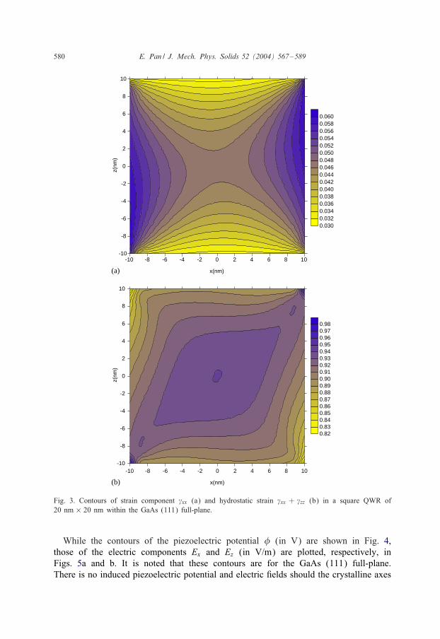
Figs. 3a and b show the corresponding contours of �xx and �xx + �zz in the squareQWR within the GaAs (111) full-plane. Comparing these two 4gures to Figs. 2a andb, we immediately observe that both the strain values and the contour shapes are
E. Pan / J. Mech. Phys. Solids 52 (2004) 567–589 579
Fig. 2. Contours of strain component �xx (a) and hydrostatic strain �xx + �zz (b) in a square QWR of20 nm × 20 nm within the GaAs (001) full-plane.
very di<erent for the two di<erently oriented GaAs semiconductors. In particular, sincethe elastic strain 4eld in GaAs (111) is singular at the four corners (Fig. 3b for thecontour concentration), one should try to avoid sharp corners when growing QWR inan inclined orientation such as the (111)-oriented.
580 E. Pan / J. Mech. Phys. Solids 52 (2004) 567–589
Fig. 3. Contours of strain component �xx (a) and hydrostatic strain �xx + �zz (b) in a square QWR of20 nm × 20 nm within the GaAs (111) full-plane.
While the contours of the piezoelectric potential (in V) are shown in Fig. 4,those of the electric components Ex and Ez (in V/m) are plotted, respectively, inFigs. 5a and b. It is noted that these contours are for the GaAs (111) full-plane.There is no induced piezoelectric potential and electric 4elds should the crystalline axes
E. Pan / J. Mech. Phys. Solids 52 (2004) 567–589 581
Fig. 4. Contours of piezoelectric potential (in V) in a square QWR of 20 nm × 20 nm within the GaAs(111) full-plane.
of the semiconductor GaAs be along the x-, y-, and z-axes, i.e., the semiconductorGaAs (001), no matter if it is for an inclusion in a full-plane or in a half-plane.This result is actually consistent with the previous well-known observation for thesuperlattice structures (Smith, 1986), but is di<erent from our recent observation forthe QD structures (Pan, 2002b) where large electric 4eld can also be induced by theQD in the GaAs (001) substrate! Furthermore, similar to the elastic strain 4eld inFigs. 3a and b, the electric 4eld singularities (Figs. 5a and b) can be clearly observedat the four corners, and therefore these points could be critical in the QWR structureanalysis.
The results that we have presented above are for a square-shaped QWR in a full-plane.However, a more realistic QWR structure model would be for the QWR within ahalf-plane, and thus the e<ect of traction-free surface needs to be addressed. Furtherconsideration is also needed for the e<ect of di<erent electric surface conditions. There-fore, in the following analysis, two di<erent electric surface conditions are studied: CaseI for the traction-free insulating surface condition, and Case II for the traction-freeconducting surface condition. Since GaAs is a weekly coupled piezoelectric material,the induced elastic 4elds are nearly identical for both cases of the surface conditions(Pan, 2002a, b). Thus, only those corresponding to the Case I surface condition arepresented for the elastic 4eld.
Figs. 6a and b show the contours of the strain component �xx and hydrostatic strain�xx + �zz in the square QWR. As we mentioned earlier, this square QWR is within theGaAs (001) half-plane and its topside is at a depth of 5 nm below the free surface.
582 E. Pan / J. Mech. Phys. Solids 52 (2004) 567–589
Fig. 5. Contours of electric components Ex (a) and Ez (b) (in V/m) in a square QWR of 20 nm × 20 nmwithin the GaAs (111) full-plane.
Comparing these two 4gures to those in the GaAs (001) full-plane (i.e., Figs. 2a andb), we observe that the free surface not only alters the contour shapes substantially, butalso increases the magnitude of the strain 4eld. For instance, compared to the full-planeresult, the strain component �xx and the hydrostatic strain have increased, respectively,about 13% and 25% due to the e<ect of the free surface.
E. Pan / J. Mech. Phys. Solids 52 (2004) 567–589 583
Fig. 6. Contours of strain component �xx (a) and hydrostatic strain �xx + �zz (b) in a square QWR of20 nm × 20 nm within the GaAs (001) half-plane.
Similarly, Figs. 7a and b plot the contours of the strain component �xx and hydro-static strain �xx + �zz in the square QWR within the GaAs (111) half-plane. Again,the inJuence of the free surface on the elastic strain distribution is clearly observedwhen compared these two 4gures to the corresponding full-plane results (Figs. 3aand b).
584 E. Pan / J. Mech. Phys. Solids 52 (2004) 567–589
Fig. 7. Contours of strain component �xx (a) and hydrostatic strain �xx+�zz (b) in a square QWR of20 nm × 20 nm within the GaAs (111) half-plane.
Although di<erent electric surface conditions result in nearly identical elastic 4eld inGaAs, they can cause totally di<erent piezoelectric 4elds. For example, Figs. 8a and bshow the contours of the piezoelectric potential (in V), respectively, correspondingto the boundary condition Cases I and II in the square QWR within the GaAs (111)
E. Pan / J. Mech. Phys. Solids 52 (2004) 567–589 585
Fig. 8. Contours of piezoelectric potential (in V) for boundary condition Case I (a) and Case II (b) in asquare QWR of 20 nm × 20 nm within the GaAs (111) full-plane.
half-plane. As can be seen, the contours for both cases are completely di<erent in termsof their shapes and magnitudes, with both of them being also distinct to that in thefull-plane (Fig. 4). In particular, it is noted that the magnitude of the potential in CaseI is roughly twice that in Case II (0.26 vs. 0.14).
586 E. Pan / J. Mech. Phys. Solids 52 (2004) 567–589
7. Conclusions
In this paper, we derived an exact closed-form solution for the Eshelby problemof polygonal inclusions in anisotropic piezoelectric full- and half-planes, assuming auniform extended eigenstrain 4eld. Based on the equivalent body-force concept ofeigenstrain, we expressed the induced elastic and piezoelectric 4elds in terms of aline integral on the boundary of the inclusion with the integrand being the line-sourceGreen’s function. Using the recently derived exact closed-form Green’s function, theline integral is carried out analytically by assuming a piecewise straight-line boundaryfor the inclusion, i.e., an arbitrarily shaped polygon. The most remarkable feature isthat the 4nal result involves only very simple elementary functions. The solution is thenapplied to a square QWR within the GaAs full- and half-planes, with results clearlyshowing the importance of material orientation and piezoelectric coupling. While thenumerical results can also serve as benchmarks and could be useful to the analysis ofnanoscale QWR structures, the corresponding multiply inclusion problem or an arrayof QWRs in the piezoelectric semiconductor substrate can be performed readily usingthe present exact closed-form solution.
Acknowledgements
The author is grateful to Dr. Gregory Rodin at The University of Texas at Austin,Dr. Frank Glas at Laboratoire de Photonique et de nanostructures of France, and Dr.David Faux at University of Surrey of UK for kindly sharing their exact isotropicresults. Communications with them have been very bene4cial to this author. One ofthe reviewers made several valuable comments, which have been incorporated into themanuscript. Dr. Nozaki kindly provided the author with a copy of his recent paper(Nozaki et al., 2001). This project was supported partially by The University of Akronunder Grant No. 2-07522.
Appendix A. Stroh Eigenvalues pJ and Eigenmatrices A and B
The eigenvalue p and eigenvector a appearing in Eq. (15) satisfy the followingeigenrelation in the (x; z)-plane:
[Q + p(R+ RT) + p2T]a = 0; (A.1)
where the superscript T denotes matrix transpose, and
QIK = C1IK1; RIK = C1IK3; TIK = C3IK3 (A.2)
with
b= (RT + pT)a = − 1p
(Q + pR)a: (A.3)
E. Pan / J. Mech. Phys. Solids 52 (2004) 567–589 587
Denoting by pm, am, and bm (m = 1; 2; : : : ; 8) the eigenvalues and the associatedeigenvectors of Eq. (A.1), we can order them in a way so that
where Im stands for the imaginary part of a complex variable and an over-bar for thecomplex conjugate. We assume that the eigenvalues pJ are distinct and the eigenvectorsaJ , and bJ satisfy the normalization relation (Barnett and Lothe, 1975; Ting, 1996)
bTI aJ + aT
I bJ = :IJ (A.5)
with :IJ being the 4 × 4 Kronecker delta, i.e., the 4 × 4 identity matrix. We alsoremark that repeated eigenvalues pJ can be avoided by using slightly perturbed materialcoeMcients with negligible errors (Pan, 1997). In doing so, the simple structure of thesolution presented in the text can always be utilized.
References
Andreev, A.D., Downes, J.R., Faux, D.A., O’Reilly, E.P., 1999. Strain distribution in quantum dots ofarbitrary shape. J. Appl. Phys. 86, 297–305.
Bacon, D.J., Barnett, D.M., Scattergood, R.O., 1978. The anisotropic continuum theory of lattice defects.Prog. Mater. Sci. 23, 51–262.
Barnett, D.M., Lothe, J., 1975. Dislocations and line charges in anisotropic piezoelectric insulators. Phys.Stat. Sol. (b) 67, 105–111.
Buryachenko, V.A., 2001. Multiparticle e<ective 4eld and related methods in micromechanics of compositematerials. Appl. Mech. Rev. 54, 1–47.
Chung, M.Y., Ting, T.C.T., 1996. Piezoelectric solid with an elliptic inclusion or hole. Int. J. Solids Struct.33, 3343–3361.
Davies, J.H., 1998. Elastic and piezoelectric 4elds around a buried quantum dot: a simple picture. J. Appl.Phys. 84, 1358–1365.
Davies, J.H., Larkin, I.A., 1994. Theory of potential modulation in lateral surface superlattices. Phys. Rev.B 49, 4800–4809.
Dong, C.Y., Lo, S.H., Cheung, Y.K., 2003. Stress analysis of inclusion problems of various shapes in anin4nite anisotropic elastic medium. Comput. Meth. Appl. Mech. Eng. 192, 683–696.
Downes, J.R., Faux, D.A., O’Reilly, E.P., 1995. InJuence of strain relaxation on the electronic properties ofburied quantum wells and wires. Mater. Sci. Eng. B35, 357–363.
Dunn, M.L., Taya, M., 1993. An analysis of piezoelectric composite materials containing ellipsoidalinhomogeneities. Proc. R. Soc. Lond. A443, 265–287.
Dunn, M.L., Wienecke, H.A., 1997. Inclusions and inhomogeneities in transversely isotropic piezoelectricsolids. Int. J. Solids Struct. 34, 3571–3582.
Eshelby, J.D., 1957. The determination of the elastic 4eld of an ellipsoidal inclusion, and related problems.Proc. R. Soc. Lond. A241, 376–396.
Eshelby, J.D., 1961. Elastic inclusions and inhomogeneities. In: Sneddon, I.N., Hill, R. (Eds.), Vol. 2,Progress in Solid Mechanics North-Holland, Amsterdam, pp. 89–140.
Faux, D.A., Pearson, G.S., 2000. Green’s tensors for anisotropic elasticity: application to quantum dots. Phys.Rev. B 62, R4798–R4801.
Faux, D.A., Downes, J.R., O’Reilly, E.P., 1996. A simple method for calculating strain distribution inquantum-wire structures. J. Appl. Phys. 80, 2515–2517.
Faux, D.A., Downes, J.R., O’Reilly, E.P., 1997. Analytic solutions for strain distribution in quantum-wirestructures. J. Appl. Phys. 82, 3754–3762.
588 E. Pan / J. Mech. Phys. Solids 52 (2004) 567–589
Freund, L.B., 2000. The mechanics of electronic materials. Int. J. Solids Struct. 37, 183–196.Freund, L.B., Gosling, T.J., 1995. Critical thickness for growth of strained quantum wires in substrate
V-grooves. Appl. Phys. Lett. 66, 2822–2824.Glas, F., 2001. Elastic relaxation of truncated pyramidal quantum dots and quantum wires in a half-space:
an analytical calculation. J. Appl. Phys. 90, 3232–3241.Glas, F., 2002a. Analytical calculation of the strain 4eld of single and periodic mis4tting polygonal wires
in a half-space. Philos. Mag. A82, 2591–2608.Glas, F., 2002b. Elastic relaxation of isolated and interacting truncated pyramidal quantum dots and quantum
wires in a half space. Appl. Surf. Sci. 188, 9–18.Glas, F., 2003. Elastic relaxation of a truncated circular cylinder with uniform dilatational eigenstrain in a
half space. Phys. Stat. Sol. B 237, 599–610.Gosling, T.J., Willis, J.R., 1995. Mechanical stability and electronic properties of buried strained quantum
wire arrays. J. Appl. Phys. 77, 5601–5610.Ju, J.W., Sun, L.Z., 2001. E<ective elastoplastic behavior of metal matrix composites containing randomly
located aligned spheroidal inhomogeneities. Part I: micromechanics-based formulation. Int. J. Solids Struct.38, 183–201.
Kawashita, M., Nozaki, H., 2001. Eshelby tensor of a polygonal inclusion and its special properties. J.Elasticity 64, 71–84.
Kogan, L., Hui, C.Y., Molkov, V., 1996. Stress and induction 4eld of a spheroidal inclusion or apenny-shaped crack in a transversely isotropic piezoelectric material. Int. J. Solids Struct. 33, 2719–2737.
Kouris, D.A., Mura, T., 1989. The elastic 4eld of a hemispherical inhomogeneity at the free surface of anelastic half space. J. Mech. Phys. Solids 37, 365–379.
Larkin, I.A., Davies, J.H., Long, A.R., Cusco, R., 1997. Theory of potential modulation in lateral surfacesuperlattices. II. Piezoelectric e<ect. Phys. Rev. B 56, 15242–15251.
Lu, P., Williams, F.W., 1998. Green’s functions of piezoelectric material with an elliptic hole or inclusion.Int. J. Solids Struct. 35, 651–664.
Markensco<, X., 1993. On the Dundurs correspondence between cavities and rigid inclusions. J. Appl. Mech.60, 260–264.
Markensco<, X., 1998a. Inclusions of uniform eigenstrains and constant or other stress dependence. J. Appl.Mech. 65, 863–866.
Markensco<, X., 1998b. Inclusions with constant eigenstress. J. Mech. Phys. Solids 46, 2297–2301.Michelitsch, T.M., Gao, H., Levin, V.M., 2003. Dynamic Eshelby tensor and potentials for ellipsoidal
inclusions. Proc. R. Soc. Lond. A459, 863–890.Mura, T., 1987. Micromechanics of Defects in Solids, 2nd Revised Edition. Kluwer Academic Publishers,
Dordrecht.Nozaki, H., Taya, M., 1997. Elastic 4elds in a polygon-shaped inclusion with uniform eigenstrains. J. Appl.
Mech. 64, 495–502.Nozaki, H., Taya, M., 2001. Elastic 4elds in a polyhedral inclusion with uniform eigenstrains and related
problems. J. Appl. Mech. 68, 441–452.Nozaki, H., Horibe, T., Taya, M., 2001. Stress 4eld caused by polygon inclusion. JSME Int. J. Series A 44,
472–482.Pan, E., 1997. A general boundary element analysis of 2-D linear elastic fracture mechanics. Int. J. Fract.
88, 41–59.Pan, E., 1999. A BEM analysis of fracture mechanics in 2D anisotropic piezoelectric solids. Eng. Anal.
Bound. Elements 23, 67–76.Pan, E., 2002a. Elastic and piezoelectric 4elds around a quantum dot: fully coupled or semi-coupled model?
J. Appl. Phys. 91, 3785–3796.Pan, E., 2002b. Elastic and piezoelectric 4elds in substrates GaAs (001) and GaAs (111) due to a buried
quantum dot. J. Appl. Phys. 91, 6379–6387.Pan, E., 2002c. Mindlin’s problem for an anisotropic piezoelectric half space with general boundary
conditions. Proc. R. Soc. Lond. A 458, 181–208.Park, S., Chuang, S., 1998. Piezoelectric e<ects on electrical and optical properties of wurtzite GaN/AlGaN
quantum well lasers. Appl. Phys. Lett. 72, 3103–3105.
E. Pan / J. Mech. Phys. Solids 52 (2004) 567–589 589
Pearson, G.S., Faux, D.A., 2000. Analytical solutions for strain in pyramidal quantum dots. J. Appl. Phys.88, 730–736.
Rahman, M., 1999a. Some problems of a rigid elliptical disk-inclusion bonded inside a transversely isotropicspace: part I. J. Appl. Mech. 66, 612–620.
Rahman, M., 1999b. Some problems of a rigid elliptical disk-inclusion bonded inside a transversely isotropicspace (Part II): solution of the integral equations. J. Appl. Mech. 66, 621–630.
Rahman, M., 2001. On the Newtonian potentials of heterogeneous ellipsoids and elliptical discs. Proc. R.Soc. Lond. A 457, 2227–2250.
Rahman, M., 2002. The isotropic ellipsoidal inclusion with a polynomial distribution of eigenstrain. J. Appl.Mech. 69, 593–601.
Rodin, G.J., 1996. Eshelby’s inclusion problem for polygons and polyhedra. J. Mech. Phys. Solids 44, 1977–1995.
Ru, C.Q., 1999. Analytical solution for Eshelby’s problem of an inclusion of arbitrary shape in a plane orhalf-plane. J. Appl. Mech. 66, 315–322.
Ru, C.Q., 2000. Eshelby’s problem for two-dimensional piezoelectric inclusions of arbitrary shape. Proc. R.Soc. Lond. A 456, 1051–1068.
Sharma, P., Sharma, R., 2003. On the Eshelby’s inclusion problem for ellipsoids with nonuniform dilatationalGaussian and exponential eigenstrains. J. Appl. Mech. 70, 418–425.
Smith, D.L., 1986. Strain-generated electric 4elds in [111] growth axis strained-layer superlattices. SolidState Commun. 57, 919–921.
Tiersten, H.F., 1969. Linear Piezoelectric Plate Vibrations. Plenum, New York.Ting, T.C.T., 1996. Anisotropic Elasticity. Oxford University Press, Oxford.Walpole, L.J., 1991. A translated rigid ellipsoidal inclusion in an elastic medium. Proc. R. Soc. Lond.
A 434, 571–585.Wang, B., 1992. Three-dimensional analysis of an ellipsoidal inclusion in a piezoelectric material. Int.
J. Solids Struct. 29, 293–308.Wang, X., Shen, Y.P., 2003. Inclusions of arbitrary shape in magnetoelectroelastic composite materials. Int.
J. Eng. Sci. 41, 85–102.Willis, J.R., 1981. Variational and related methods for the overall properties of composites. Advances Appl.
Mech. 21, 1–78.Withers, P.J., 1989. The determination of the elastic 4eld of an ellipsoidal inclusion in a transversely isotropic
medium, and its relevance to composite materials. Philos. Mag. A 59, 759–781.Yu, H.Y., Sanday, S.C., 1991. Elastic 4eld in joined semi-in4nite solids with an inclusion. Proc. R. Soc.
Lond. A 434, 521–530.Yu, H.Y., Sanday, S.C., Chang, C.I., 1994. Elastic inclusion and inhomogeneities in transversely isotropic