ESIJET ™ Printing Technology Ross N. Mills Imaging Technology International Corporation, Boulder, Colorado Abstract Impulse or Drop-On-Demand ink jet printing technologies such as piezoelectric and thermal (bubble) account for a major segment of the non-impact printing market. An alter- native impulse ink jet technology is electrostatic ink jet. Al- though electrostatic ink jet was first patented for printing application in the 1950's and several products or prototypes have been introduced, technical issues have prevented the technology from being successful in the non-impact print- ing market. This paper will discuss the history and the physics of operation of single channel and multi-channel electrostatic ink jet. In addition, a new print head applica- tion of ElectroStatic Ink JET known as ESIJET™ (pro- nounced “easy jet”) will be introduced. Introduction Drop-On-Demand ink jet printing is currently dominated by thermal (bubble) ink jet and piezoelectric ink jet technology. 1 While significantly different in mechanism, both types transfer ink by the interaction of a pressure wave created in an ink cavity with a negative pressure ink meniscus residing in a nozzle. This interaction projects an ink volume from the nozzle to the paper in the form of individually controlled drops. The acoustic “push” mechanism makes both technologies susceptible to drop outs due to ingested air bubbles in the driver ink cavity. This is especially true for piezoelectric technology which has a larger cavity volume. Piezoelectric technology generally enjoys a more well behaved drop formation process due to higher ink viscosity and has a wider latitude for ink formulation when compared to thermal ink jet. The relatively low packing density of piezoelectric drivers generally leads to higher cost and bulkier print head assemblies. While the packing density of bubble jet is considerably more efficient, ink drying and color bleeding problems continue to be troublesome for the water based inks required in thermal ink jet systems. 2 In addition, the relatively small nozzle size for both technologies (approximately 50 μm for 300 dpi) requires careful attention to ink formulation, ink filtering and nozzle exit maintenance. If some or all of these inherent problems can be mitigated by the introduction of an alternate ink jet technology which maintains or improves cost, performance and quality, then clearly the market acceptance of ink jet printing will continue to be enhanced. Electrostatic or Elec- trohydrodynamic ink jet is such a technology. Electrostatic ink jet draws on assets of both electrophotographic and ink jet technology to offer a unique printing system. The two inhibitors to the technology have been excessive drive voltage and inadequate manufacturability. An understanding of single channel operation, a meth- od for reducing the driving voltage and applying this knowledge to multi-channel operation are the key steps to demonstrating product feasibility. In addition, manufactur- ability of large arrays of nozzles at low cost must also be demonstrated. Single Channel Operation A liquid will deform in the presence of an electrostatic field. This phenomenon was first documented by Gilbert in 1600. 3 He noted that a droplet of water on a flat surface will deform into a conical shape when a piece of electrostatical- ly charged amber is held near it. It was the investigative work of Sir Geoffrey I. Taylor 4 in the early 1960's which gave rise to the term “Taylor cone” to describe the shape re- sulting from the balance of electrostatic, gravitational, sur- face tension and internal pressure forces acting on a small volume of liquid exposed to an electrostatic field. The field attempts to pull the atoms in the liquid out along the field gradient while surface tension attempts to hold the liquid flat. Both the electrostatic and surface tension forces are in- versely proportional to the square of the radius of curvature of the liquid surface. The sharper the curvature of the liq- uid, the more intensely the electrostatic field pulls it out and the greater the surface tension force attempting to restore it to a flat surface. The result is a conical shape with a half- angle of 49.3 degrees which is independent of the fluid properties. At the tip of an idealized Taylor cone, both the electrostatic field intensity and the surface tension forces become infinite. Before this occurs in practice, a thin fila- ment of fluid is drawn out from the tip of the cone along the electrostatic field gradient. Thus the nozzle and meniscus system can be referred to as the filament nucleation site (FNS) It is this phenomenon which forms the basis for ElectrosStatic Ink JET (ESIJET™) printing. The use of electrostatic ink jet in printing technologies has been investigated by a number of researchers since the middle of this century. 5-11 In the last five years, investiga- tors at Fuji Xerox Co. have been studying the combination of electrostatic ink jet and thermal ink jet. 12 Matsushita Electric Industrial Co. has started to examine the possibili- ty of a multi-nozzle air assisted electrostatic ink jets. 13-16 The last three years have seen some renewed interest in sin- gle channel investigations. Most notable among these is the work at IBM 17,18 in which they have characterized single channel operation and demonstrated both single nozzle bi- nary and continuous tone printing. Recent Progress in Ink Jet Technologies II 286 Chapter 5, Alternative Ink Jet Recent Progress in Ink Jet Technologies II Copyright 1999, IS&T
Transcript
ESIJET ™ Printing TechnologyRoss N. Mills
Imaging Technology International Corporation, Boulder, Colorado
Abstract
Impulse or Drop-On-Demand ink jet printing technologiessuch as piezoelectric and thermal (bubble) account for amajor segment of the non-impact printing market. An alter-native impulse ink jet technology is electrostatic ink jet. Al-though electrostatic ink jet was first patented for printingapplication in the 1950's and several products or prototypeshave been introduced, technical issues have prevented thetechnology from being successful in the non-impact print-ing market. This paper will discuss the history and thephysics of operation of single channel and multi-channelelectrostatic ink jet. In addition, a new print head applica-tion of ElectroStatic Ink JET known as ESIJET™ (pro-nounced “easy jet”) will be introduced.
Introduction
Drop-On-Demand ink jet printing is currently dominatedby thermal (bubble) ink jet and piezoelectric ink jettechnology.1 While significantly different in mechanism,both types transfer ink by the interaction of a pressure wavecreated in an ink cavity with a negative pressure inkmeniscus residing in a nozzle. This interaction projects anink volume from the nozzle to the paper in the form ofindividually controlled drops. The acoustic “push”mechanism makes both technologies susceptible to dropouts due to ingested air bubbles in the driver ink cavity.This is especially true for piezoelectric technology whichhas a larger cavity volume. Piezoelectric technologygenerally enjoys a more well behaved drop formationprocess due to higher ink viscosity and has a wider latitudefor ink formulation when compared to thermal ink jet. Therelatively low packing density of piezoelectric driversgenerally leads to higher cost and bulkier print headassemblies. While the packing density of bubble jet isconsiderably more efficient, ink drying and color bleedingproblems continue to be troublesome for the water basedinks required in thermal ink jet systems.2 In addition, therelatively small nozzle size for both technologies(approximately 50 µm for 300 dpi) requires carefulattention to ink formulation, ink filtering and nozzle exitmaintenance. If some or all of these inherent problems canbe mitigated by the introduction of an alternate ink jettechnology which maintains or improves cost, performanceand quality, then clearly the market acceptance of ink jetprinting will continue to be enhanced. Electrostatic or Elec-trohydrodynamic ink jet is such a technology. Electrostaticink jet draws on assets of both electrophotographic and inkjet technology to offer a unique printing system. The two
inhibitors to the technology have been excessive drivevoltage and inadequate manufacturability.
An understanding of single channel operation, a meth-od for reducing the driving voltage and applying thisknowledge to multi-channel operation are the key steps todemonstrating product feasibility. In addition, manufactur-ability of large arrays of nozzles at low cost must also bedemonstrated.
Single Channel Operation
A liquid will deform in the presence of an electrostaticfield. This phenomenon was first documented by Gilbert in1600.3 He noted that a droplet of water on a flat surface willdeform into a conical shape when a piece of electrostatical-ly charged amber is held near it. It was the investigativework of Sir Geoffrey I. Taylor4 in the early 1960's whichgave rise to the term “Taylor cone” to describe the shape re-sulting from the balance of electrostatic, gravitational, sur-face tension and internal pressure forces acting on a smallvolume of liquid exposed to an electrostatic field. The fieldattempts to pull the atoms in the liquid out along the fieldgradient while surface tension attempts to hold the liquidflat. Both the electrostatic and surface tension forces are in-versely proportional to the square of the radius of curvatureof the liquid surface. The sharper the curvature of the liq-uid, the more intensely the electrostatic field pulls it out andthe greater the surface tension force attempting to restore itto a flat surface. The result is a conical shape with a half-angle of 49.3 degrees which is independent of the fluidproperties. At the tip of an idealized Taylor cone, both theelectrostatic field intensity and the surface tension forcesbecome infinite. Before this occurs in practice, a thin fila-ment of fluid is drawn out from the tip of the cone along theelectrostatic field gradient. Thus the nozzle and meniscussystem can be referred to as the filament nucleation site(FNS) It is this phenomenon which forms the basis forElectrosStatic Ink JET (ESIJET™) printing.
The use of electrostatic ink jet in printing technologieshas been investigated by a number of researchers since themiddle of this century.5-11 In the last five years, investiga-tors at Fuji Xerox Co. have been studying the combinationof electrostatic ink jet and thermal ink jet.12 MatsushitaElectric Industrial Co. has started to examine the possibili-ty of a multi-nozzle air assisted electrostatic ink jets.13-16
The last three years have seen some renewed interest in sin-gle channel investigations. Most notable among these is thework at IBM 17,18 in which they have characterized singlechannel operation and demonstrated both single nozzle bi-nary and continuous tone printing.
Recent Progress in Ink Jet Technologies II 286 Chapter 5, Alternative Ink Jet
Recent Progress in Ink Jet Technologies II Copyright 1999, IS&T
In single channel operation the paper is transported onor across a platen which is electrically grounded relative tothe conductive FNS. The FNS (which for single channeloperation consists of a section of tubing with an inside di-ameter of 250 m and a wall thickness of 50 m) is positionedat a distance of 1 to 1.5 mm from the platen (a wide varietyof tube sizes and gaps can be used). This FNS exit size istypically large when compared to conventional ink jet(about 5 times in diameter) and results in a clog-free, highreliability component. This is a key factor in the ability ofthis technology to be extended to a large number array ofFNS's without a significant yield problem. The FNS isplumbed to a reservoir of ink which is maintained at a levelof about 2 cm above the nozzle exit.
In addition to the geometry, the jetting is dependent onthe properties of the ink including viscosity, surface ten-sion, density, electric conductivity and dielectric constant.It has been shown that for a fixed geometry, a jetting re-gime exists for which the diameter of the stream and themass/charge flow rate depend only on the fluid propertiesof the ink and not on the electronic driving characteris-tics.18 Thus the amount of ink transferred to paper can beprecisely controlled by modulating the voltage pulse widthwhich makes continuous tone printing possible by modu-lating the spot size on paper. The maximum repetition rateand minimum pulse width for extraction of a given ink isdependent on the charge relaxation time and the flow tran-sient time. Repetition rates of up to 10 kHz have been re-ported in the literature for single spot size and 1 kHz for256 spot size levels.16,18
By employing a CCD video camera with high magni-fication optics, a standard VHS video cassette recorder, anda stroboscopic light source, it is possible to observe the for-mation of the filament nucleation site and the migration ofthe filament of ink from the nozzle to the platen. A se-quence of video photomicrographs shown in Figure 1 illus-trates the actual transfer of a large volume filament of inkfollowed by a small volume. The voltage as a function ofevent timing for Figure 1 is shown in Figure 2.
Multi-Channel Operation
Peizo and Thermal drop-on-demand ink jet technologymake use of multiple channels to attain a throughputnecessary for high quality printing that is cost andperformance competitive with laser printers. Since ESIJET(printing is a drop-on-demand technology, multi-channelarrays will be necessary. A sequence showing the operationof three FNS's is illustrated in Figure 3. As can beobserved, there is very little interaction between thefilaments when all three are operating synchronously.However, when the FNS's are operating in the asyn-chronous mode and or when the FNS's are made on closercenter to center spacing, the interaction of the electrostaticfields can be significant enough to cause large displace-ments of the filaments which results in spot placementerror and poor print quality.
The traditional FNS drive methods are shown in Fig-ure 4. The Pulse Only Method relies on switching the entirevoltage magnitude necessary to cause filament formation
and migration to the substrate. Since the voltage required toinitiate the filament for normal printing parameters can beas much as 1200 to 1600 volts, the switching or pulse driveelectronics can be quite expensive. It is possible to reducethe switching voltage to the range of 500 to 800 volts by ap-plying a bias voltage of 800 to 1100 volts to either the plat-en or the FNS. The Opposite and Same Sign Bias/PulseMethods use this technique to reduce switching voltage asshown in Figure 4. However, this method still requires dis-crete electronic components for the drive voltage to initiatethe filament. As a result, the cost of the electronics wouldprohibit the use of arrays with a large number of FNS's. Analternate driving technology called the Shadow PulseMethod (Patent Pending) is shown in the lower part of Fig-ure 4. In this method, a sub threshold pulse that is synchro-nous with the print clock is superimposed on the dc bias
Figure 1. ESIJET™ single channel printing sequence.
Figure 2. Print head voltage sequence.
TIMEVOLTAGE
V BIAS
V PULSE
(platten)
(nozzle)
t5 t1 0 t1 5
PW1 PW2
Period = 1 / Repetition Rate
Recent Progress in Ink Jet Technologies II 287 Chapter 5, Alternative Ink Jet
Recent Progress in Ink Jet Technologies II Copyright 1999, IS&T
voltage and applied to all of the FNS's in the array. This“shadow pulse” voltage is switched by one high voltagediscrete transistor for the entire array. When a print posi-tion is needed, only the difference between the shadowpulse plus bias and the print voltage is switched. In thismethod, the bias voltage is 800 to 1000 volts, the shadowpulse voltage is 400 to 700 volts and the print pulse voltageis 100 to 150 volts. Thus, only the print pulse voltage isswitched at each of the FNS's of the array and low cost ICpackages can be used. A print sample using the ShadowPulse Method is shown in Figure 5.
Multi-Channel Array Fabrication
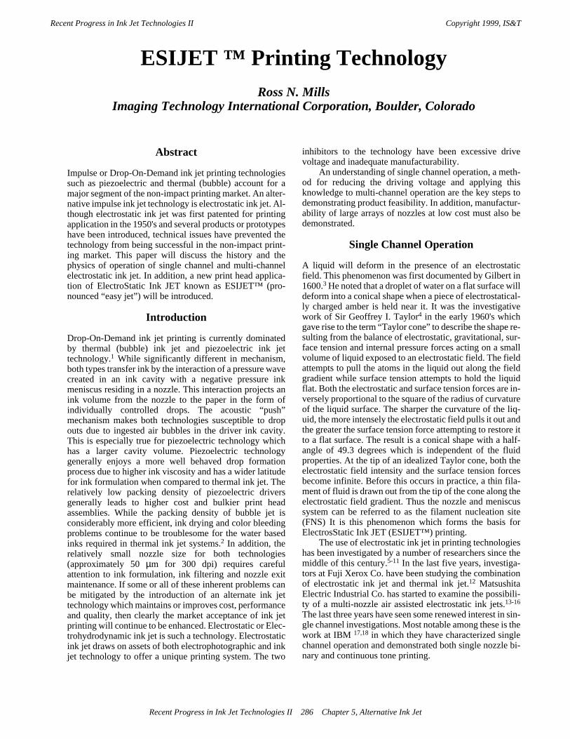
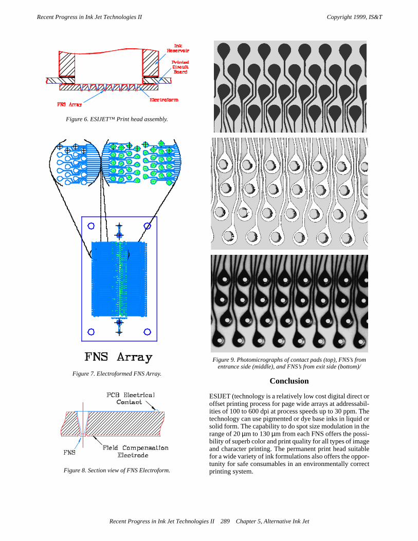
The ESIJET (print head shown in Figure 6 (PatentPending) consists of three basic components. The firstcomponent is the Electroform (EF) which contains thearray of Filament Nucleation Sites (FNS). The second isthe printed circuit board (PCB) which supports andinterfaces the FNS array to the drive electronics and inksupply. The ink supply is the third component of the printhead.
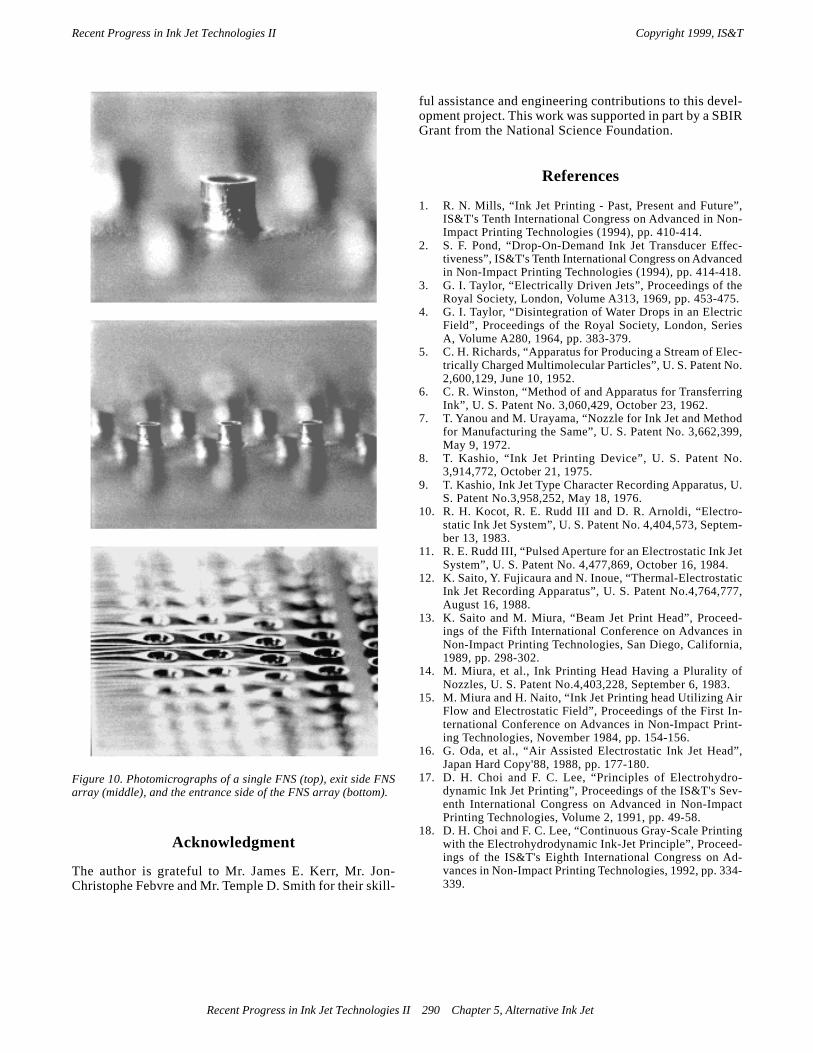
A drawing of the electroform is shown in Figure 7.This particular design has 8 rows of FNS's spaced center tocenter at 0.040" within and between rows. The array is ap-proximately 1.5" long and 0.30" wide with 300 FNS's. Thebody of the array, which also serves as the mandrel forelectroforming the FNS's, is fabricated by a molding pro-cess for plastic such as polycarbonate. The cross sectionview in Figure 8 shows that each FNS has a truncated coneshape with a 0.028" diameter, 0.004" wide flange at thebase or fluid entry side; a 0.010" tip or fluid exit side diam-eter with a 0.0015" wall thickness and a height of 0.032".The FNS exit projection above the surface of the plastic isnecessary to provide a focal point for the electrostatic fieldand to provide a physical boundary to prevent meniscuswetting. The Field Compensation Electrode shown in Fig-ure 10 is used to reduce crosstalk by simulating a nearestneighbor to the peripheral FNS's. Each FNS is electro-formed using a nickel-cobalt/nickel/gold process. Photo-graphs of a portion of the EF-FNS array showing the exitside, entry side and contact pads are shown in Figure 9.Note that the exterior walls of the FNS are visible throughthe transparent plastic. High magnification views of theexit side and the entry side are shown in Figure 10. As canbe observed, the process is very consistent both within theFNS and among the FNS's.
Figure 5. Multi-channel printing (3.6 mil ink spot size).
Vprint
Vbias
-V pulse
0
Vprint
Vbias
0
Vshadow
Shadow Pulse Method time
time
Opposite Bias/PulseMethod
Pulse OnlyMethod
Same Sign Bias/PulseMethod
Recent Progress in Ink Jet Technologies II 288 Chapter 5, Alternative Ink Jet
Recent Progress in Ink Jet Technologies II Copyright 1999, IS&T
Conclusion
ESIJET (technology is a relatively low cost digital direct oroffset printing process for page wide arrays at addressabil-ities of 100 to 600 dpi at process speeds up to 30 ppm. Thetechnology can use pigmented or dye base inks in liquid orsolid form. The capability to do spot size modulation in therange of 20 µm to 130 µm from each FNS offers the possi-bility of superb color and print quality for all types of imageand character printing. The permanent print head suitablefor a wide variety of ink formulations also offers the oppor-tunity for safe consumables in an environmentally correctprinting system.
Figure 6. ESIJET™ Print head assembly.
Figure 7. Electroformed FNS Array.
Figure 8. Section view of FNS Electroform.
Figure 9. Photomicrographs of contact pads (top), FNS’s from entrance side (middle), and FNS’s from exit side (bottom)/
Recent Progress in Ink Jet Technologies II 289 Chapter 5, Alternative Ink Jet
Recent Progress in Ink Jet Technologies II Copyright 1999, IS&T
Recent Progress in Ink Jet Technologies II 290 Chapter 5, Alternative Ink Jet
Acknowledgment
The author is grateful to Mr. James E. Kerr, Mr. Jon-Christophe Febvre and Mr. Temple D. Smith for their skill-
ful assistance and engineering contributions to this devel-opment project. This work was supported in part by a SBIRGrant from the National Science Foundation.
References
1. R. N. Mills, “Ink Jet Printing - Past, Present and Future”,IS&T's Tenth International Congress on Advanced in Non-Impact Printing Technologies (1994), pp. 410-414.
2. S. F. Pond, “Drop-On-Demand Ink Jet Transducer Effec-tiveness”, IS&T's Tenth International Congress on Advancedin Non-Impact Printing Technologies (1994), pp. 414-418.
3. G. I. Taylor, “Electrically Driven Jets”, Proceedings of theRoyal Society, London, Volume A313, 1969, pp. 453-475.
4. G. I. Taylor, “Disintegration of Water Drops in an ElectricField”, Proceedings of the Royal Society, London, SeriesA, Volume A280, 1964, pp. 383-379.
5. C. H. Richards, “Apparatus for Producing a Stream of Elec-trically Charged Multimolecular Particles”, U. S. Patent No.2,600,129, June 10, 1952.
6. C. R. Winston, “Method of and Apparatus for TransferringInk”, U. S. Patent No. 3,060,429, October 23, 1962.
7. T. Yanou and M. Urayama, “Nozzle for Ink Jet and Methodfor Manufacturing the Same”, U. S. Patent No. 3,662,399,May 9, 1972.
8. T. Kashio, “Ink Jet Printing Device”, U. S. Patent No.3,914,772, October 21, 1975.
9. T. Kashio, Ink Jet Type Character Recording Apparatus, U.S. Patent No.3,958,252, May 18, 1976.
10. R. H. Kocot, R. E. Rudd III and D. R. Arnoldi, “Electro-static Ink Jet System”, U. S. Patent No. 4,404,573, Septem-ber 13, 1983.
11. R. E. Rudd III, “Pulsed Aperture for an Electrostatic Ink JetSystem”, U. S. Patent No. 4,477,869, October 16, 1984.
12. K. Saito, Y. Fujicaura and N. Inoue, “Thermal-ElectrostaticInk Jet Recording Apparatus”, U. S. Patent No.4,764,777,August 16, 1988.
13. K. Saito and M. Miura, “Beam Jet Print Head”, Proceed-ings of the Fifth International Conference on Advances inNon-Impact Printing Technologies, San Diego, California,1989, pp. 298-302.
14. M. Miura, et al., Ink Printing Head Having a Plurality ofNozzles, U. S. Patent No.4,403,228, September 6, 1983.
15. M. Miura and H. Naito, “Ink Jet Printing head Utilizing AirFlow and Electrostatic Field”, Proceedings of the First In-ternational Conference on Advances in Non-Impact Print-ing Technologies, November 1984, pp. 154-156.
16. G. Oda, et al., “Air Assisted Electrostatic Ink Jet Head”,Japan Hard Copy'88, 1988, pp. 177-180.
17. D. H. Choi and F. C. Lee, “Principles of Electrohydro-dynamic Ink Jet Printing”, Proceedings of the IS&T's Sev-enth International Congress on Advanced in Non-ImpactPrinting Technologies, Volume 2, 1991, pp. 49-58.
18. D. H. Choi and F. C. Lee, “Continuous Gray-Scale Printingwith the Electrohydrodynamic Ink-Jet Principle”, Proceed-ings of the IS&T's Eighth International Congress on Ad-vances in Non-Impact Printing Technologies, 1992, pp. 334-339.
Figure 10. Photomicrographs of a single FNS (top), exit side FNSarray (middle), and the entrance side of the FNS array (bottom).
Recent Progress in Ink Jet Technologies II Copyright 1999, IS&T