62
System Operating Manual ESPRIMO E4xx / E5xx

SystemOperating Manual
ESPRIMO E4xx / E5xx
Thank you for buying an innovative product from Fujitsu.
Latest information about our products, useful tips, updates etc. is availableon our website: "http://www.fujitsu.com/fts/"
You can find driver updates at: "http://support.ts.fujitsu.com/download"
Should you have any technical questions, please contact:
• our Hotline/Service Desk (see Service Desk list or from the Internet at:"http://support.ts.fujitsu.com/contact/servicedesk")
• Your sales partner
• Your sales office
We hope you enjoy using your new Fujitsu system!


Published by / Contact address in the EU
Fujitsu Technology Solutions GmbH
Mies-van-der-Rohe-Straße 8
80807 Munich, Germany
"http://www.fujitsu.com/fts/"
Copyright© Fujitsu Technology Solutions GmbH 2013. All rights reserved.
Publication Date02/2013
Order No.: A26361-K1185-Z320-1-7619, edition 1
ESPRIMO E4xx / E5xx
Operating Manual
Your ESPRIMO 5
Important notes 7
Ports and operating elements 11
Getting started 13
Operation 22
Problem solutions and tips 27
System expansions 31
Technical specification 55
Index 56
Remarks
Information on the product description meets the design specifications of Fujitsu andis provided for comparison purposes. Several factors may cause the actual results todiffer. Technical data is subject to change without prior notification. Fujitsu rejects anyresponsibility with regard to technical or editorial mistakes or omissions.
Trademarks
Fujitsu, the Fujitsu logo and ESPRIMO are registered trademarks of Fujitsu Limited or itssubsidiaries in the United States of America and other countries.
Kensington, MicroSaver and K-Slot are registered trademarks of ACCO Brands.
Microsoft and Windows are trademarks or registered trademarks of the MicrosoftCorporation in the United States and/or other countries.
All other trademarks specified here are the property of their respective owners.
Copyright
No part of this publication may be copied, reproduced or translated withoutthe prior written consent of Fujitsu.
No part of this publication may be saved or transferred by any electronic meanswithout the written approval of Fujitsu.

Contents
ContentsYour ESPRIMO . . . . . . . . . . . . . . . . . . . . . . . . . . . . . . . . . . . . . . . . . . . . . . . . . . . . . . . . . . . . . . . . . . . . . . . . . 5Validity of the Reference Manual . . . . . . . . . . . . . . . . . . . . . . . . . . . . . . . . . . . . . . . . . . . . . . . . . . . . . . . . . 5Notational conventions . . . . . . . . . . . . . . . . . . . . . . . . . . . . . . . . . . . . . . . . . . . . . . . . . . . . . . . . . . . . . . . . . . 6
Important notes . . . . . . . . . . . . . . . . . . . . . . . . . . . . . . . . . . . . . . . . . . . . . . . . . . . . . . . . . . . . . . . . . . . . . . . . 7Safety information . . . . . . . . . . . . . . . . . . . . . . . . . . . . . . . . . . . . . . . . . . . . . . . . . . . . . . . . . . . . . . . . . . . . . . . 7Transporting the device . . . . . . . . . . . . . . . . . . . . . . . . . . . . . . . . . . . . . . . . . . . . . . . . . . . . . . . . . . . . . . . . . . 7Cleaning the device . . . . . . . . . . . . . . . . . . . . . . . . . . . . . . . . . . . . . . . . . . . . . . . . . . . . . . . . . . . . . . . . . . . . . 8Energy saving, disposal and recycling . . . . . . . . . . . . . . . . . . . . . . . . . . . . . . . . . . . . . . . . . . . . . . . . . . . . 8CE marking . . . . . . . . . . . . . . . . . . . . . . . . . . . . . . . . . . . . . . . . . . . . . . . . . . . . . . . . . . . . . . . . . . . . . . . . . . . . 9FCC Compliance Statement . . . . . . . . . . . . . . . . . . . . . . . . . . . . . . . . . . . . . . . . . . . . . . . . . . . . . . . . . . . . . 10
FCC Class B Compliance Statement . . . . . . . . . . . . . . . . . . . . . . . . . . . . . . . . . . . . . . . . . . . . . . . . . . 10FCC Radiation Exposure Statement . . . . . . . . . . . . . . . . . . . . . . . . . . . . . . . . . . . . . . . . . . . . . . . . . . 10
Ports and operating elements . . . . . . . . . . . . . . . . . . . . . . . . . . . . . . . . . . . . . . . . . . . . . . . . . . . . . . . . . 11Front . . . . . . . . . . . . . . . . . . . . . . . . . . . . . . . . . . . . . . . . . . . . . . . . . . . . . . . . . . . . . . . . . . . . . . . . . . . . . . . . . . . 11Rear . . . . . . . . . . . . . . . . . . . . . . . . . . . . . . . . . . . . . . . . . . . . . . . . . . . . . . . . . . . . . . . . . . . . . . . . . . . . . . . . . . . 12
Getting started . . . . . . . . . . . . . . . . . . . . . . . . . . . . . . . . . . . . . . . . . . . . . . . . . . . . . . . . . . . . . . . . . . . . . . . . . 13Unpacking and checking the delivery . . . . . . . . . . . . . . . . . . . . . . . . . . . . . . . . . . . . . . . . . . . . . . . . . . . . . 13Steps for initial setup . . . . . . . . . . . . . . . . . . . . . . . . . . . . . . . . . . . . . . . . . . . . . . . . . . . . . . . . . . . . . . . . . . . . 13Setting up the device . . . . . . . . . . . . . . . . . . . . . . . . . . . . . . . . . . . . . . . . . . . . . . . . . . . . . . . . . . . . . . . . . . . . 14
Vertical operating position (optional) . . . . . . . . . . . . . . . . . . . . . . . . . . . . . . . . . . . . . . . . . . . . . . . . . . 15Connecting the device to the mains supply . . . . . . . . . . . . . . . . . . . . . . . . . . . . . . . . . . . . . . . . . . . . . . . . 15Switching on for the first time: installing the software . . . . . . . . . . . . . . . . . . . . . . . . . . . . . . . . . . . . . . . 16
Switching on monitor and device . . . . . . . . . . . . . . . . . . . . . . . . . . . . . . . . . . . . . . . . . . . . . . . . . . . . . 17Installing the software . . . . . . . . . . . . . . . . . . . . . . . . . . . . . . . . . . . . . . . . . . . . . . . . . . . . . . . . . . . . . . . 17
Connecting external devices . . . . . . . . . . . . . . . . . . . . . . . . . . . . . . . . . . . . . . . . . . . . . . . . . . . . . . . . . . . . . 18Connecting the cables . . . . . . . . . . . . . . . . . . . . . . . . . . . . . . . . . . . . . . . . . . . . . . . . . . . . . . . . . . . . . . . 18Disconnecting the cables . . . . . . . . . . . . . . . . . . . . . . . . . . . . . . . . . . . . . . . . . . . . . . . . . . . . . . . . . . . . 18Ports on the device . . . . . . . . . . . . . . . . . . . . . . . . . . . . . . . . . . . . . . . . . . . . . . . . . . . . . . . . . . . . . . . . . . 19Connecting a monitor . . . . . . . . . . . . . . . . . . . . . . . . . . . . . . . . . . . . . . . . . . . . . . . . . . . . . . . . . . . . . . . . 19Connecting the mouse . . . . . . . . . . . . . . . . . . . . . . . . . . . . . . . . . . . . . . . . . . . . . . . . . . . . . . . . . . . . . . . 20Connecting the keyboard . . . . . . . . . . . . . . . . . . . . . . . . . . . . . . . . . . . . . . . . . . . . . . . . . . . . . . . . . . . . 20Connecting external devices to the serial interface . . . . . . . . . . . . . . . . . . . . . . . . . . . . . . . . . . . . . 21Connecting external devices to the USB ports . . . . . . . . . . . . . . . . . . . . . . . . . . . . . . . . . . . . . . . . . 21
Operation . . . . . . . . . . . . . . . . . . . . . . . . . . . . . . . . . . . . . . . . . . . . . . . . . . . . . . . . . . . . . . . . . . . . . . . . . . . . . . 22Switch the device on . . . . . . . . . . . . . . . . . . . . . . . . . . . . . . . . . . . . . . . . . . . . . . . . . . . . . . . . . . . . . . . . . . . . 22Switching off the device . . . . . . . . . . . . . . . . . . . . . . . . . . . . . . . . . . . . . . . . . . . . . . . . . . . . . . . . . . . . . . . . . 22Indicators on the device . . . . . . . . . . . . . . . . . . . . . . . . . . . . . . . . . . . . . . . . . . . . . . . . . . . . . . . . . . . . . . . . . 23Keyboard . . . . . . . . . . . . . . . . . . . . . . . . . . . . . . . . . . . . . . . . . . . . . . . . . . . . . . . . . . . . . . . . . . . . . . . . . . . . . . . 24
Important keys and keyboard shortcuts . . . . . . . . . . . . . . . . . . . . . . . . . . . . . . . . . . . . . . . . . . . . . . . . 24Settings in BIOS Setup . . . . . . . . . . . . . . . . . . . . . . . . . . . . . . . . . . . . . . . . . . . . . . . . . . . . . . . . . . . . . . . . . . 25Property and data protection . . . . . . . . . . . . . . . . . . . . . . . . . . . . . . . . . . . . . . . . . . . . . . . . . . . . . . . . . . . . . 26
Anti-theft protection and lead-sealing . . . . . . . . . . . . . . . . . . . . . . . . . . . . . . . . . . . . . . . . . . . . . . . . . . 26
Problem solutions and tips . . . . . . . . . . . . . . . . . . . . . . . . . . . . . . . . . . . . . . . . . . . . . . . . . . . . . . . . . . . . 27Help if problems occur . . . . . . . . . . . . . . . . . . . . . . . . . . . . . . . . . . . . . . . . . . . . . . . . . . . . . . . . . . . . . . . . . . . 27Troubleshooting . . . . . . . . . . . . . . . . . . . . . . . . . . . . . . . . . . . . . . . . . . . . . . . . . . . . . . . . . . . . . . . . . . . . . . . . . 27
Power indicator remains off after you have switched on your device . . . . . . . . . . . . . . . . . . . . . 27The device cannot be switched off with the ON/OFF switch . . . . . . . . . . . . . . . . . . . . . . . . . . . . . 28
Fujitsu 3

Contents
Monitor remains blank . . . . . . . . . . . . . . . . . . . . . . . . . . . . . . . . . . . . . . . . . . . . . . . . . . . . . . . . . . . . . . . 28No mouse pointer displayed on the screen . . . . . . . . . . . . . . . . . . . . . . . . . . . . . . . . . . . . . . . . . . . . 29Time and/or date is not correct . . . . . . . . . . . . . . . . . . . . . . . . . . . . . . . . . . . . . . . . . . . . . . . . . . . . . . . 29Error messages on the screen . . . . . . . . . . . . . . . . . . . . . . . . . . . . . . . . . . . . . . . . . . . . . . . . . . . . . . . . 29
Installing new software . . . . . . . . . . . . . . . . . . . . . . . . . . . . . . . . . . . . . . . . . . . . . . . . . . . . . . . . . . . . . . . . . . 30Restoring the hard disk contents . . . . . . . . . . . . . . . . . . . . . . . . . . . . . . . . . . . . . . . . . . . . . . . . . . . . . . . . . 30Tips . . . . . . . . . . . . . . . . . . . . . . . . . . . . . . . . . . . . . . . . . . . . . . . . . . . . . . . . . . . . . . . . . . . . . . . . . . . . . . . . . . . . 30
System expansions . . . . . . . . . . . . . . . . . . . . . . . . . . . . . . . . . . . . . . . . . . . . . . . . . . . . . . . . . . . . . . . . . . . . 31Information about boards . . . . . . . . . . . . . . . . . . . . . . . . . . . . . . . . . . . . . . . . . . . . . . . . . . . . . . . . . . . . . . . . 32Opening the casing . . . . . . . . . . . . . . . . . . . . . . . . . . . . . . . . . . . . . . . . . . . . . . . . . . . . . . . . . . . . . . . . . . . . . 33
Removing a cover . . . . . . . . . . . . . . . . . . . . . . . . . . . . . . . . . . . . . . . . . . . . . . . . . . . . . . . . . . . . . . . . . . . 33Removing the front panel . . . . . . . . . . . . . . . . . . . . . . . . . . . . . . . . . . . . . . . . . . . . . . . . . . . . . . . . . . . . 34
Close the casing . . . . . . . . . . . . . . . . . . . . . . . . . . . . . . . . . . . . . . . . . . . . . . . . . . . . . . . . . . . . . . . . . . . . . . . . 35Securing the front panel . . . . . . . . . . . . . . . . . . . . . . . . . . . . . . . . . . . . . . . . . . . . . . . . . . . . . . . . . . . . . 35Reattaching the cover . . . . . . . . . . . . . . . . . . . . . . . . . . . . . . . . . . . . . . . . . . . . . . . . . . . . . . . . . . . . . . . 36
Removing the drive carrier . . . . . . . . . . . . . . . . . . . . . . . . . . . . . . . . . . . . . . . . . . . . . . . . . . . . . . . . . . . . . . . 37Installing the drive cage . . . . . . . . . . . . . . . . . . . . . . . . . . . . . . . . . . . . . . . . . . . . . . . . . . . . . . . . . . . . . . . . . 38Installing and removing drives . . . . . . . . . . . . . . . . . . . . . . . . . . . . . . . . . . . . . . . . . . . . . . . . . . . . . . . . . . . . 39
Removing and installing accessible drives . . . . . . . . . . . . . . . . . . . . . . . . . . . . . . . . . . . . . . . . . . . . . 39Removing a hard disk drive . . . . . . . . . . . . . . . . . . . . . . . . . . . . . . . . . . . . . . . . . . . . . . . . . . . . . . . . . . 46Installing a hard disk drive . . . . . . . . . . . . . . . . . . . . . . . . . . . . . . . . . . . . . . . . . . . . . . . . . . . . . . . . . . . 48
Installing and removing heat sinks . . . . . . . . . . . . . . . . . . . . . . . . . . . . . . . . . . . . . . . . . . . . . . . . . . . . . . . . 50Removing the heat sink . . . . . . . . . . . . . . . . . . . . . . . . . . . . . . . . . . . . . . . . . . . . . . . . . . . . . . . . . . . . . . 50Installing the heat sink . . . . . . . . . . . . . . . . . . . . . . . . . . . . . . . . . . . . . . . . . . . . . . . . . . . . . . . . . . . . . . . 50
Assembling and dismantling low-profile units . . . . . . . . . . . . . . . . . . . . . . . . . . . . . . . . . . . . . . . . . . . . . . 51Removing a slot cover . . . . . . . . . . . . . . . . . . . . . . . . . . . . . . . . . . . . . . . . . . . . . . . . . . . . . . . . . . . . . . . 51Installing a board . . . . . . . . . . . . . . . . . . . . . . . . . . . . . . . . . . . . . . . . . . . . . . . . . . . . . . . . . . . . . . . . . . . . 52Removing boards . . . . . . . . . . . . . . . . . . . . . . . . . . . . . . . . . . . . . . . . . . . . . . . . . . . . . . . . . . . . . . . . . . . 52Reinstalling a slot cover . . . . . . . . . . . . . . . . . . . . . . . . . . . . . . . . . . . . . . . . . . . . . . . . . . . . . . . . . . . . . . 53
Mainboard expansions . . . . . . . . . . . . . . . . . . . . . . . . . . . . . . . . . . . . . . . . . . . . . . . . . . . . . . . . . . . . . . . . . . 53Upgrading main memory . . . . . . . . . . . . . . . . . . . . . . . . . . . . . . . . . . . . . . . . . . . . . . . . . . . . . . . . . . . . . 53Processor, replacing . . . . . . . . . . . . . . . . . . . . . . . . . . . . . . . . . . . . . . . . . . . . . . . . . . . . . . . . . . . . . . . . . 53Replacing the lithium battery . . . . . . . . . . . . . . . . . . . . . . . . . . . . . . . . . . . . . . . . . . . . . . . . . . . . . . . . . 54
Technical specification . . . . . . . . . . . . . . . . . . . . . . . . . . . . . . . . . . . . . . . . . . . . . . . . . . . . . . . . . . . . . . . . . 55
Index . . . . . . . . . . . . . . . . . . . . . . . . . . . . . . . . . . . . . . . . . . . . . . . . . . . . . . . . . . . . . . . . . . . . . . . . . . . . . . . . . . 56
4 Fujitsu
Your ESPRIMO
Your ESPRIMOOverview
... is available with various configuration levels which differ in terms of hardware and softwareequipment. You can install additional drives (for example a DVD drive) and other boards.
This manual tells you how to start using your device and how to operate it in daily use.This manual applies for all configuration levels. Depending on the chosen configurationlevel, some of the hardware components described may not be available on your PC.Please also read the notes about your operating system.
Depending on the configuration selected, the operating system is preinstalledon your hard disk (e.g. Windows).
Further information on this device is provided:
• in the "Quick Start Guide" poster
• in the "Safety/regulations" manual
• in the "Warranty" manual
• in the operating manual for the monitor
• in the manual for the mainboard
• in your operating system documentation
• in the information files (e.g. *.PDF, *.HTML, *.DOC, *.CHM, *.TXT, *.HLP)
Some of the manuals listed can be found in electronic form on the "Drivers & Utilities" DVD.
You can access and view the required information using the Acrobat Readerprogram, which is also included on the DVD. You can of course alsoprint out a copy of the manual if you prefer.
Validity of the Reference ManualThis Reference Manual is valid for the following systems:
• ESPRIMO E410
• ESPRIMO E420
• ESPRIMO E520
Fujitsu 5

Your ESPRIMO
Notational conventionsPay particular attention to text marked with this symbol. Failure to observethese warnings could pose a risk to health, damage the device or leadto loss of data. The warranty will be invalidated if the device becomesdefective through failure to observe these warnings.
Indicates important information for the proper use of the device.
► Indicates an activity that must be performed
Indicates a result
This font indicates data entered using the keyboard in a program dialogue or atthe command line, e.g. your password (Name123) or a command used tostart a program (start.exe)
This font indicates information that is displayed on the screen by a program, e.g.:Installation is complete.
This font indicates
• terms and texts used in a software interface, e.g.: Click on Save
• names of programs or files, e.g. Windows or setup.exe.
"This font" indicates
• cross-references to another section, e.g. "Safety information"
• cross-references to an external source, e.g. a web address: For moreinformation, go to "http://www.fujitsu.com/fts/"
• Names of CDs, DVDs and titles or designations for other materials,e.g.: "CD/DVD Drivers & Utilities" or "Safety/Regulations" manual
Key indicates a key on the keyboard, e.g: F10
This font indicates terms and texts that are emphasised or highlighted, e.g.: Donot switch off the device
6 Fujitsu
Important notes
Important notesImportantnotesNotes
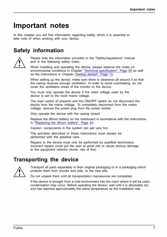
In this chapter you will find information regarding safety which it is essential totake note of when working with your device.
Safety informationSafetyinformationNote
Please note the information provided in the "Safety/regulations" manualand in the following safety notes.
When installing and operating the device, please observe the notes onenvironmental conditions in Chapter "Technical specification", Page 55 as wellas the instructions in Chapter "Getting started", Page 13.
When setting up the device, make sure there is clearance all around it so thatthe casing receives enough ventilation. In order to avoid overheating, do notcover the ventilation areas of the monitor or the device.
You must only operate the device if the rated voltage used by thedevice is set to the local mains voltage.
The main switch (if present) and the ON/OFF switch do not disconnect thedevice from the mains voltage. To completely disconnect from the mainsvoltage, remove the power plug from the power socket.
Only operate the device with the casing closed.
Replace the lithium battery on the mainboard in accordance with the instructionsin "Replacing the lithium battery", Page 54.
Caution, components in the system can get very hot.
The activities described in these instructions must always beperformed with the greatest care.
Repairs to the device must only be performed by qualified technicians.Incorrect repairs could put the user at great risk or cause serious damageto the equipment (electric shock, risk of fire).
Transporting the deviceDevice,TransportationRetransportation
Transport all parts separately in their original packaging or in a packaging whichprotects them from knocks and jolts, to the new site.
Do not unpack them until all transportation manoeuvres are completed.
If the device is brought from a cold environment into the room where it will be used,condensation may occur. Before operating the device, wait until it is absolutely dryand has reached approximately the same temperature as the installation site.
Fujitsu 7

Important notes
Cleaning the deviceDevice,TransportationRetransportationSystemunit,seeDevice
Turn off all power and equipment switches and disconnect the powerplug from the mains outlet.
Do not clean any interior parts yourself, leave this job to a service technician.
Do not use any cleaning agents that contain abrasives or may corrodeplastic (alcohol, thinner or acetone).
Never clean the device with water! Water entering into the device couldpresent a serious risk to users (e.g. electric shock).
Ensure that no liquid enters the system.
The surface can be cleaned with a dry cloth. If particularly dirty, use a cloth that has beenmoistened in mild domestic detergent and then carefully wrung out.
Use disinfectant wipes to clean the keyboard and the mouse.
Energy saving, disposal and recyclingDisposalEnergysavingRecyclingDrivers&UtilitiesDVDUserDocumentationDVD
You can find information on these subjects on the "Drivers & Utilities" DVD or on ourwebsite ("http://www.fujitsu.com/fts/about/fts/environment-care/").
8 Fujitsu

Important notes
CE markingCEmarkingCEmarkingNotesElectromagneticcompatibilityLowvoltagedirective
The shipped version of this device complies with the requirements of European Uniondirectives 2004/108/EC "Electromagnetic compatibility", 2006/95/EC "Low voltage directive" and2009/125/EC "Ecodesign".
CE marking for devices with radio component
This equipment complies with the requirements of Directive 1999/5/EC of the European Parliamentand Commission from 9 March, 1999 governing Radio and Telecommunications Equipmentand mutual recognition of conformity.
The CE marking valid for your device can be found on the device label.
Explanation: CE nnnn (!) ; nnnn defines the type of CE marking and the exclamation markindicates a device with radio components.
You can find more information and declarations of conformity on the Internet at:"http://globalsp.ts.fujitsu.com/sites/certificates".
This equipment can be used in the following countries:
Belgium Bulgaria Denmark Germany
Estonia Finland France Greece
UK Ireland Iceland Italy
Croatia Latvia Liechtenstein Lithuania
Luxembourg Malta Netherlands Norway
Austria Poland Portugal Rumania
Sweden Switzerland Slovakia Slovenia
Spain Czech Republic Hungary Cyprus
Contact the corresponding government office in the respective country for current information onpossible operating restrictions. If your country is not included in the list, then please contactthe corresponding supervisory authority as to whether the use of this product is permitted inyour country.
Fujitsu 9
Important notes
FCC Compliance StatementIf the device complies with the FCC regulations, the FCC sign can be found on the type rating plate.
FCC Class B Compliance StatementDOC (INDUSTRY CANADA) NOTICESNotice to Users of Radios and Television:
This class B digital apparatus complies with Canadian ICES-003.
The following statement applies to the products covered in this manual, unless otherwise specifiedherein. The statement for other products will appear in the accompanying documentation.
NOTE:
This equipment has been tested and found to comply with the limits for a "Class B" digitaldevice, pursuant to Part 15 of the FCC rules and meets all requirements of the CanadianInterference-Causing Equipment Standard ICES-003 for digital apparatus. These limits aredesigned to provide reasonable protection against harmful interference in a residential installation.This equipment generates, uses and can radiate radio frequency energy and, if not installedand used in strict accordance with the instructions, may cause harmful interference to radiocommunications. However, there is no guarantee that interference will not occur in a particularinstallation. If this equipment does cause harmful interference to radio or television reception,which can be determined by turning the equipment off and on, the user is encouraged totry to correct the interference by one or more of the following measures:
• Reorient or relocate the receiving antenna.
• Increase the separation between equipment and the receiver.
• Connect the equipment into an outlet on a circuit different from that towhich the receiver is connected.
• Consult the dealer or an experienced radio/TV technician for help.
Fujitsu is not responsible for any radio or television interference caused by unauthorizedmodifications of this equipment or the substitution or attachment of connecting cables andequipment other than those specified by Fujitsu. The correction of interferences caused by suchunauthorized modification, substitution or attachment will be the responsibility of the user.
The use of shielded I/O cables is required when connecting this equipment to any and all optionalperipheral or host devices. Failure to do so may violate FCC and ICES rules.
FCC Radiation Exposure StatementThis equipment complies with FCC radiation exposure limits set forth for an uncontrolled environment.
The transmitters in this device must not be co-located or operated in conjunctionwith any other antenna or transmitter.
To prevent radio interference to the licensed service, this device is intended to beoperated indoors and away from windows to provide maximum shielding. Equipment (orits transmit antenna) that is installed outdoors is subject to licensing.
Users are not authorized to modify this product. Any modifications invalidate the warranty.
This equipment may not be modified, altered, or changed in any way without signedwritten permission from Fujitsu. Unauthorized modification will void the equipmentauthorization from the FCC and Industry Canada and the warranty.
10 Fujitsu

Ports and operating elements
Ports and operating elementsPorts
This chapter presents the individual hardware components of your device. This will provideyou with an overview of the ports and operating elements on the device. Please familiariseyourself with these components before starting to work with your device.
Front
1 5 6 7
2 3
1 4
1 = USB ports
2 = Headphone port
3 = Microphone port
4 = 3 1/2 inch module bay
5 = ON/OFF switch
6 = Optical drive (optional)
7 = Insert/eject button (CD/DVD)
Fujitsu 11

Ports and operating elements
Rear
2 1
1 = Slot covers 2 = Alternating voltage socket (AC IN)
12 Fujitsu
Getting started
Getting startedGettingstarted
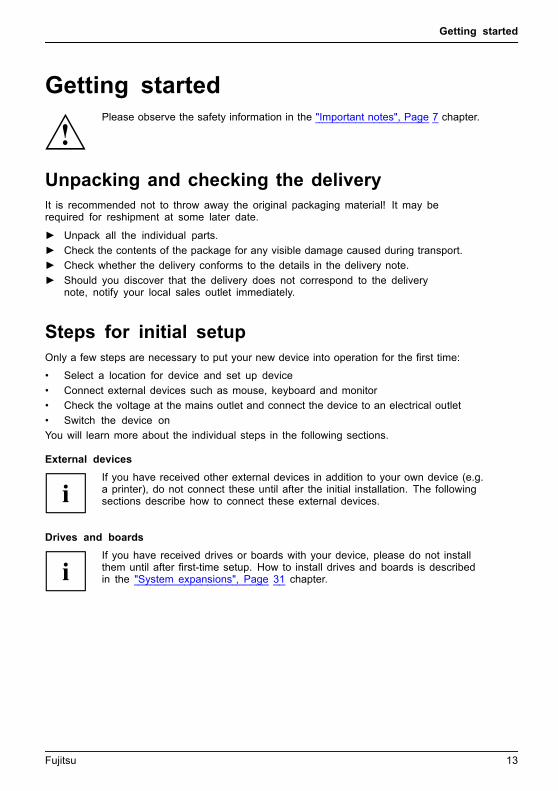
Please observe the safety information in the "Important notes", Page 7 chapter.
Unpacking and checking the deliveryIt is recommended not to throw away the original packaging material! It may berequired for reshipment at some later date.PackagingContentsofdeliveryPackaging,
► Unpack all the individual parts.
► Check the contents of the package for any visible damage caused during transport.
► Check whether the delivery conforms to the details in the delivery note.
► Should you discover that the delivery does not correspond to the deliverynote, notify your local sales outlet immediately.
Steps for initial setupPreparingforfirstuse,overviewPreparingforuse,
Only a few steps are necessary to put your new device into operation for the first time:
• Select a location for device and set up device
• Connect external devices such as mouse, keyboard and monitor
• Check the voltage at the mains outlet and connect the device to an electrical outlet
• Switch the device on
You will learn more about the individual steps in the following sections.
External devices
If you have received other external devices in addition to your own device (e.g.a printer), do not connect these until after the initial installation. The followingsections describe how to connect these external devices.
Drives and boards
If you have received drives or boards with your device, please do not installthem until after first-time setup. How to install drives and boards is describedin the "System expansions", Page 31 chapter.
Fujitsu 13

Getting started
Setting up the deviceVideoworkstationErgonomicDevice,
You can set up and operate the device in either a vertical or horizontal position.
When installing your device, please read the recommendations andsafety notes in the "Safety" manual.
Use the device simply in the horizontal operating position. With the aid of suitablefeet, it is also possible to use the device in the vertical operating position..
We recommend that you place your device on a surface with good anti-slip qualities.In view of the multitude of different finishes and varnishes used on furniture, it ispossible that the rubber feet will mark the surface they stand on.
Depending on the location of your device, bothersome vibrations and noises mayoccur. To prevent this, a distance of at least 10 mm / 0.39 inch should be maintainedfrom other devices on casing sides without ventilation surfaces.
To ensure the casing receives adequate ventilation, when setting up thedevice make sure that there is sufficient clearance around it as indicatedin the chapter "Technical specification", Page 55.
In order to avoid overheating, do not cover the ventilation areasof the monitor or the device.
Do not stack several devices on top of each other.
A minimum distance of 200 mm / 7.87 inch from the device mustbe observed for ventilation areas.
Do not expose the device to extreme ambient conditions (see "Technical specification",Page 55, "Ambient conditions"). Protect the device against dust, humidity and heat.
14 Fujitsu
Getting started
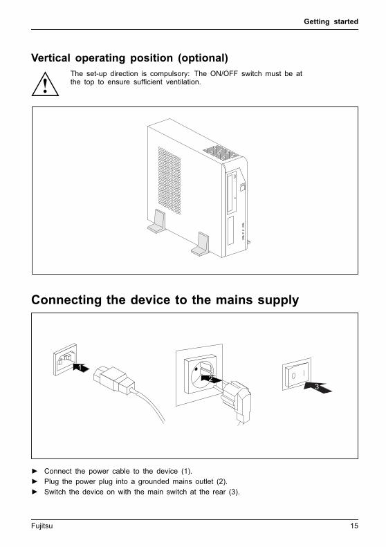
Vertical operating position (optional)The set-up direction is compulsory: The ON/OFF switch must be atthe top to ensure sufficient ventilation.
Connecting the device to the mains supplyMainsadapter
21
3
► Connect the power cable to the device (1).
► Plug the power plug into a grounded mains outlet (2).
► Switch the device on with the main switch at the rear (3).
Fujitsu 15
Getting started
Switching on for the first time: installing the softwareInstalling,Software,Installing,
Once the installation has been started the device must not be switchedoff, unless the installation has been completed.
During installation, the device may only be rebooted when you are requested to do so!
The installation will otherwise not be carried out correctly and the contentsof the hard disk must be completely restored.
If the device is integrated into a network, the user and server details as well asthe network protocol are required during the software installation.
Contact your network administrator if you have any questions about these settings.
When you switch on the device for the first time, the supplied softwareis installed and configured. Plan a reasonable amount of time for this,as this process must not be interrupted.
You may need the licence number for Windows during the installation. The licencenumber is located on a label on your device.
16 Fujitsu
Getting started
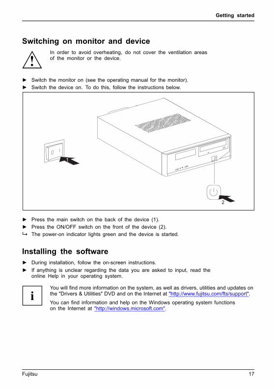
Switching on monitor and deviceIn order to avoid overheating, do not cover the ventilation areasof the monitor or the device.
► Switch the monitor on (see the operating manual for the monitor).
► Switch the device on. To do this, follow the instructions below.
1
2
► Press the main switch on the back of the device (1).
► Press the ON/OFF switch on the front of the device (2).
The power-on indicator lights green and the device is started.
Installing the software► During installation, follow the on-screen instructions.
Software,Installing,
► If anything is unclear regarding the data you are asked to input, read theonline Help in your operating system.
You will find more information on the system, as well as drivers, utilities and updates onthe "Drivers & Utilities" DVD and on the Internet at "http://www.fujitsu.com/fts/support".
You can find information and help on the Windows operating system functionson the Internet at "http://windows.microsoft.com".
Fujitsu 17
Getting started
Connecting external devicesRead the documentation on the external device before connecting it.
With the exception of USB devices, always remove all power plugsbefore connecting external devices!
Do not connect or disconnect cables during a thunderstorm.
Always take hold of the actual plug. Never unplug a cable by pulling the cable itself.
Connect and disconnect the cables in the order described below.
Connecting the cables► Turn off all power and equipment switches.
CordCable,
► Remove all power plugs from the grounded mains outlets.
► Connect all the cables to the device and the external devices. Please make sure that youalways observe the safety notes provided in "Important notes", Page 7.
► Plug all data communication cables into the appropriate sockets.
► Plug all power cables into the grounded mains outlets.
USB devices are hot-pluggable. This means you can connect and disconnectUSB cables while your device is switched on.
Additional information can be found in "Connecting external devices to the USBports", Page 21 and in the documentation for the USB devices.
Disconnecting the cables► Switch off all affected devices.
Cable,
► Remove all power plugs from the grounded mains outlets.
► Unplug all data communication cables from the appropriate sockets.
► Disconnect all of the cables from the device and from the external devices.
18 Fujitsu
Getting started
Ports on the deviceInterfacesExternaldevices,Device,
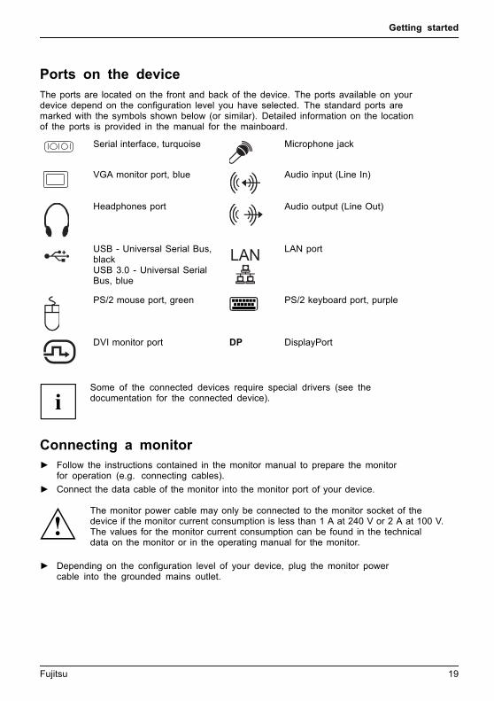
The ports are located on the front and back of the device. The ports available on yourdevice depend on the configuration level you have selected. The standard ports aremarked with the symbols shown below (or similar). Detailed information on the locationof the ports is provided in the manual for the mainboard.
Serial interface, turquoiseSerialinterface
Microphone jackMicrophoneport
VGA monitor port, blueMonitorport
Audio input (Line In)AudioinputLinein
Headphones portHeadphones
Audio output (Line Out)AudiooutputLineout
USB - Universal Serial Bus,blackUSB 3.0 - Universal SerialBus, blueUniversalSerialBus
LAN LAN portLANport
PS/2 mouse port, greenMouseportPS/2mouseport
PS/2 keyboard port, purpleKeyboardport
DVI monitor portMonitorport
DP DisplayPort
Some of the connected devices require special drivers (see thedocumentation for the connected device).
Connecting a monitor► Follow the instructions contained in the monitor manual to prepare the monitor
for operation (e.g. connecting cables).Monitor
► Connect the data cable of the monitor into the monitor port of your device.
The monitor power cable may only be connected to the monitor socket of thedevice if the monitor current consumption is less than 1 A at 240 V or 2 A at 100 V.The values for the monitor current consumption can be found in the technicaldata on the monitor or in the operating manual for the monitor.
► Depending on the configuration level of your device, plug the monitor powercable into the grounded mains outlet.
Fujitsu 19
Getting started
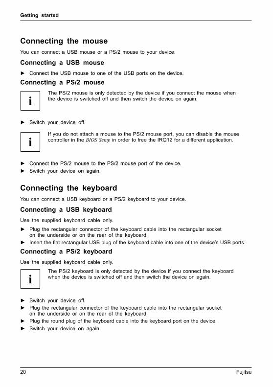
Connecting the mouseYou can connect a USB mouse or a PS/2 mouse to your device.Mouse,Connecting,
Connecting a USB mouse
► Connect the USB mouse to one of the USB ports on the device.USBport,USBport
Connecting a PS/2 mouse
The PS/2 mouse is only detected by the device if you connect the mouse whenthe device is switched off and then switch the device on again.
► Switch your device off.
If you do not attach a mouse to the PS/2 mouse port, you can disable the mousecontroller in the BIOS Setup in order to free the IRQ12 for a different application.
► Connect the PS/2 mouse to the PS/2 mouse port of the device.PS/2mouse,Connecting,PS/2mouse,
► Switch your device on again.
Connecting the keyboardYou can connect a USB keyboard or a PS/2 keyboard to your device.Keyboard,Connecting,
Connecting a USB keyboard
Use the supplied keyboard cable only.USBport,Connecting,
► Plug the rectangular connector of the keyboard cable into the rectangular socketon the underside or on the rear of the keyboard.
► Insert the flat rectangular USB plug of the keyboard cable into one of the device’s USB ports.USBport
Connecting a PS/2 keyboard
Use the supplied keyboard cable only.ConnectingaPS/2keyboardConnecting,
The PS/2 keyboard is only detected by the device if you connect the keyboardwhen the device is switched off and then switch the device on again.
► Switch your device off.
► Plug the rectangular connector of the keyboard cable into the rectangular socketon the underside or on the rear of the keyboard.
► Plug the round plug of the keyboard cable into the keyboard port on the device.Keyboard,
► Switch your device on again.
20 Fujitsu
Getting started
Connecting external devices to the serial interfaceSerialinterfaceSerialinterface,Externaldevices,Devices,
External devices can be connected to the serial interface (e.g. a printer or modem).
► Connect the data cable to the external device.
► Connect the data cable to the corresponding serial interface.
For an exact description of how to connect external devices to the correspondingport, please see the external device documentation.
Port settingsSerialinterface,
You can change the port settings (e.g. address, interrupt) in the BIOS Setup.
Device driversDevicedrivers,
The devices connected to the serial interface require drivers. Your operating systemalready includes many drivers. If the required drive is missing, install it. The latestdrivers are usually available on the Internet or will be supplied on a data carrier.
Connecting external devices to the USB portsUSBdevices,USBport,Externaldevices,Devices,
You can connect a wide range of external devices to the USB ports (e.g.printer, scanner, modem or keyboard).
USB devices are hot-pluggable. This means you can connect and disconnectUSB cables while your device is switched on.
Additional information can be found in the documentation for the USB devices.
► Connect the data cable to the external device.
► Connect the data cable to one of the USB ports on your device.
Device drivers
The external USB devices you connect to the USB ports usually require no driver of theirown, as the required software is already included in the operating system. If the devicerequires separate software, please note the information in the manufacturer’s manual.
To ensure the transmission capacity of USB 2.0, the cable from the external USB deviceto the USB port of your device must not be longer than 3 m / 118,11 inch.
Fujitsu 21

Operation
Operation
Switch the device on► If necessary, switch the monitor on (see the operating manual for the monitor).
Device,Monitor,
► Switch on the device using the main power switch located on the rear of the device (if present).
► Press the ON/OFF switch on the front of the device.
The power indicator glows and the device starts.
Switching off the device► Shut down the operating system in the proper way.
Device,Monitor,
► If the operating system does not automatically switch the device into energy-saving mode orswitch it off, press the ON/OFF switch. Warning, this could lead to a loss of data!
► Switch the device off at the main switch.
The device consumes energy as follows (depending on the power supply of your device):
• Device with alternating voltage socket, monitor socket and emergency on button: low energy
• Device with alternating voltage socket and main power switch: no energy
• Device with alternating voltage socket and monitor socket: low energy
The main switch and the ON/OFF switch do not disconnect the devicefrom the mains voltage. To completely disconnect from the mains voltage,remove the power plug from the power socket.
► If necessary, switch the monitor off (see the operating manual for the monitor).
22 Fujitsu
Operation
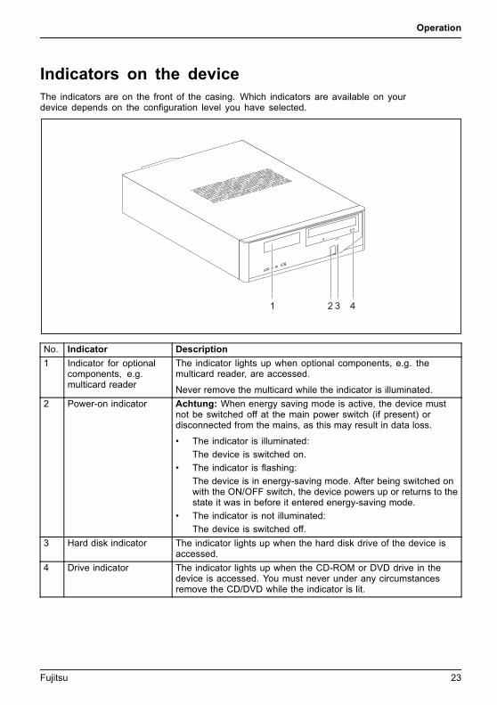
Indicators on the deviceIndicators,Device
The indicators are on the front of the casing. Which indicators are available on yourdevice depends on the configuration level you have selected.
1 2 3 4
No. Indicator Description
1 Indicator for optionalcomponents, e.g.multicard reader
The indicator lights up when optional components, e.g. themulticard reader, are accessed.
Never remove the multicard while the indicator is illuminated.
2 Power-on indicator Achtung: When energy saving mode is active, the device mustnot be switched off at the main power switch (if present) ordisconnected from the mains, as this may result in data loss.
• The indicator is illuminated:
The device is switched on.
• The indicator is flashing:
The device is in energy-saving mode. After being switched onwith the ON/OFF switch, the device powers up or returns to thestate it was in before it entered energy-saving mode.
• The indicator is not illuminated:
The device is switched off.
3 Hard disk indicator The indicator lights up when the hard disk drive of the device isaccessed.
4 Drive indicator The indicator lights up when the CD-ROM or DVD drive in thedevice is accessed. You must never under any circumstancesremove the CD/DVD while the indicator is lit.
Fujitsu 23

Operation
KeyboardKeyboardKeyboard,Keyboard,Keyboard,Keyboard,Keyboard,AlphanumerickeypadCursorkeysKeys,FunctionkeysNumerickeypadNumerickeypad
The illustrated keyboard is an example and may differ from the model you use.
1 2
3 4 5
1 = Function keys
2 = On/off switch (optional)
3 = Alphanumeric keypad
4 = Cursor keys
5 = Numeric keypad (calculator keypad)
Important keys and keyboard shortcutsKeysKeyboardshortcuts
The description of the following keys and keyboard shortcuts applies to Microsoftoperating systems. Details of other keys and keyboard shortcuts can be found inthe documentation for the relevant application program.
Key / key combination DescriptionON/OFFswitchButton,
On/off switch (optional)
Depending on the setting in the BIOS Setup, the device can be switchedon or off with this switch. Some operating systems allow you to configureadditional functions of the ON/OFF switch in the Control Panel.
With some keyboards the ON/OFF switch can only be used with an ACPI(Advanced Configuration and Power Management Interface). Otherwisethe key is inoperative. The mainboard must support this function.Keys,Keys,Keys,
Enter key
confirms the highlighted selection. The Enter key is also referred to asthe "Return" key.
24 Fujitsu
Operation
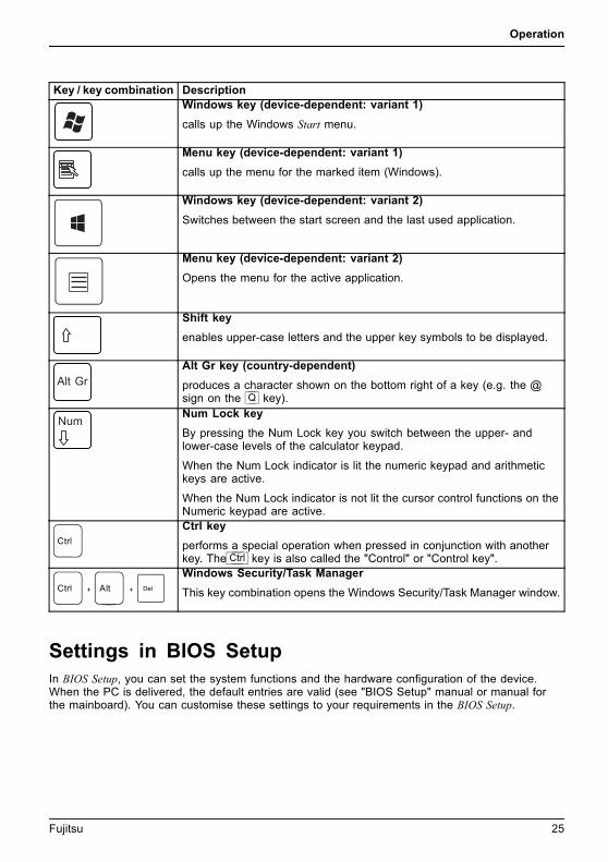
Key / key combination DescriptionKeys,
Windows key (device-dependent: variant 1)
calls up the Windows Start menu.Keys,
Menu key (device-dependent: variant 1)
calls up the menu for the marked item (Windows).Keys
Windows key (device-dependent: variant 2)
Switches between the start screen and the last used application.
Keys
Menu key (device-dependent: variant 2)
Opens the menu for the active application.
Keys,Keys,
Shift key
enables upper-case letters and the upper key symbols to be displayed.Keys,
Alt Gr key (country-dependent)
produces a character shown on the bottom right of a key (e.g. the @sign on the Q key).Keys,
Num Lock key
By pressing the Num Lock key you switch between the upper- andlower-case levels of the calculator keypad.
When the Num Lock indicator is lit the numeric keypad and arithmetickeys are active.
When the Num Lock indicator is not lit the cursor control functions on theNumeric keypad are active.
Ctrl
Keys,KeysKeysKeys,
Ctrl key
performs a special operation when pressed in conjunction with anotherkey. The Ctrl key is also called the "Control" or "Control key".
AltCtrl Del+ +
Ctrl+Alt+DelCtrl+Alt+DelKeyskeyboardshortcuts
Windows Security/Task Manager
This key combination opens the Windows Security/Task Manager window.
Settings in BIOS SetupBIOSSetup,Systemsettings,BIOSSetup,BIOSSetup,BIOSSetupSetup,
In BIOS Setup, you can set the system functions and the hardware configuration of the device.When the PC is delivered, the default entries are valid (see "BIOS Setup" manual or manual forthe mainboard). You can customise these settings to your requirements in the BIOS Setup.
Fujitsu 25

Operation
Property and data protectionPropertyprotectionDataprotectionSecuritymeasures
Software functions and mechanical locking offer a broad range of functions for protecting yourdevice and your personal data from unauthorised access. You can also combine these functions.
Anti-theft protection and lead-sealingDevice,Device,Casing,Lead-sealingAnti-theftprotectionSecurityLockChain
1
2
1 = Holes for padlock/lead-seal 2 = Device for Security Lock
Anti-theft protection
You can protect your device from theft
• with the holes (1), a padlock and a chain, which you have connected to a fixed object beforehand.
• with the Security Lock device (2) and a Kensington MicroSaver. Pleaseconsult the manual for your Security Lock.
Lead-sealing
The casing can be sealed to prevent it being opened by unauthorised persons. To do this, feedthe sealing chain through the holes (1) and seal the chain with the lead seal.
26 Fujitsu

Problem solutions and tips
Problem solutions and tipsComply with the safety information in the "Safety" manual and the chapter"Getting started", Page 13, when attaching or detaching cables.
If a fault occurs, try to rectify it in accordance with the measures described in the following documents:
• in this chapter
• in the documentation relating to the peripheral devices
• in the Help sections for the individual programs
• in the documentation for the operating system in use.
Help if problems occurShould you encounter a problem with your computer that you cannot resolve yourself:
► Note the ID number of your device. The ID number is found on the type ratingplate on the back, the underside or the top of the casing.
► For further clarification of the problem, contact the Service Desk for your country (see theService Desk list or visit the Internet at "http://support.ts.fujitsu.com/contact/servicedesk"). Whenyou do this, please have ready the identity number and serial number of your system.
Troubleshooting
Power indicator remains off after you have switchedon your deviceCause Remedy
The mains voltage supply is faulty. ► Check that the power cable is correctlyplugged into the device and into a groundedmains outlet.
► Check that the main switch at the rear of themonitor is set to the "I" position.
► Switch the device on.
Internal power supply overloaded. ► Pull the power plug of the device out of themains outlet.
► Wait for about 3 minutes.
► Plug the power plug into a properly groundedmains outlet again.
► Switch the device on.
Fujitsu 27
Problem solutions and tips
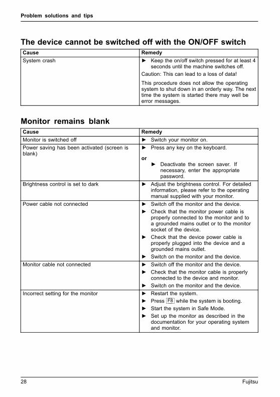
The device cannot be switched off with the ON/OFF switchCause Remedy
System crash ► Keep the on/off switch pressed for at least 4seconds until the machine switches off.
Caution: This can lead to a loss of data!
This procedure does not allow the operatingsystem to shut down in an orderly way. The nexttime the system is started there may well beerror messages.
Monitor remains blankCause Remedy
Monitor is switched off ► Switch your monitor on.
Power saving has been activated (screen isblank)
► Press any key on the keyboard.
or► Deactivate the screen saver. If
necessary, enter the appropriatepassword.
Brightness control is set to dark ► Adjust the brightness control. For detailedinformation, please refer to the operatingmanual supplied with your monitor.
Power cable not connected ► Switch off the monitor and the device.
► Check that the monitor power cable isproperly connected to the monitor and toa grounded mains outlet or to the monitorsocket of the device.
► Check that the device power cable isproperly plugged into the device and agrounded mains outlet.
► Switch on the monitor and the device.
Monitor cable not connected ► Switch off the monitor and the device.
► Check that the monitor cable is properlyconnected to the device and monitor.
► Switch on the monitor and the device.
Incorrect setting for the monitor ► Restart the system.
► Press F8 while the system is booting.
► Start the system in Safe Mode.
► Set up the monitor as described in thedocumentation for your operating systemand monitor.
28 Fujitsu

Problem solutions and tips
No mouse pointer displayed on the screenCause Remedy
The mouse is not correctly connected. ► Shut down the operating system properly.
► Switch the device off.
► Check that the mouse cable is properlyconnected to the system unit. If you use anadapter or extension lead with the mousecable, check the connections.
► Switch the device on.
The mouse controller is not enabled. ► Check in the BIOS-Setup whether the mousecontroller is enabled.
► Check that the mouse driver is properlyinstalled and is present when the applicationprogramme is started. Detailed informationcan be found in the user guide for the mouseand application programme.
Time and/or date is not correctCause Remedy
Time and date are incorrect. ► Set the correct time and date within theoperating system you are using.
or► Set the correct time and/or date in the
BIOS Setup.
The lithium battery is discharged. ► If the time and date are repeatedly wrongwhen you switch on your device, replace thelithium battery (see "Replacing the lithiumbattery", Page 54).
Error messages on the screenError messages and their explanations are provided:
• in the technical manual for the mainboard
• in the documentation for the programs used
Fujitsu 29
Problem solutions and tips
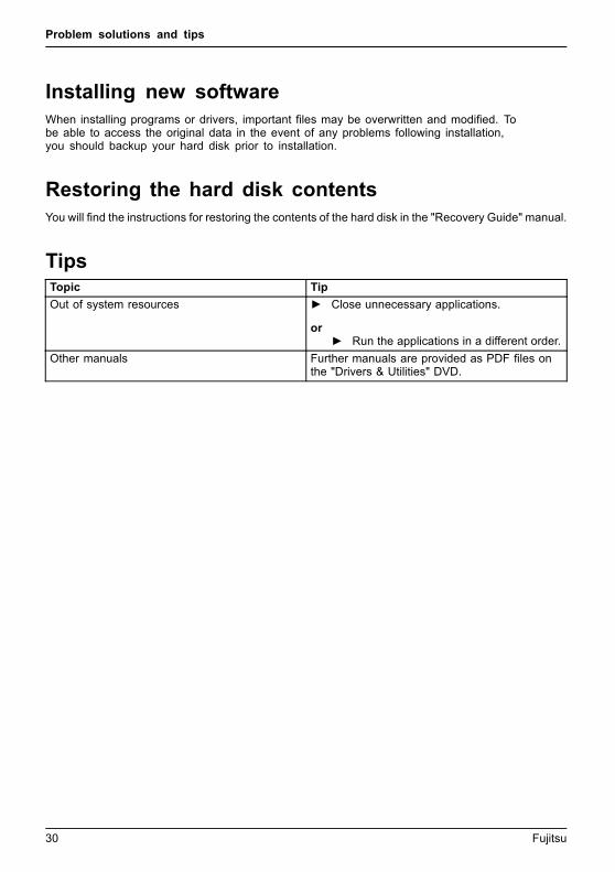
Installing new softwareWhen installing programs or drivers, important files may be overwritten and modified. Tobe able to access the original data in the event of any problems following installation,you should backup your hard disk prior to installation.
Restoring the hard disk contentsYou will find the instructions for restoring the contents of the hard disk in the "Recovery Guide" manual.
TipsTopic Tip
Out of system resources ► Close unnecessary applications.
or► Run the applications in a different order.
Other manuals Further manuals are provided as PDF files onthe "Drivers & Utilities" DVD.
30 Fujitsu

System expansions
System expansionsUpgrades,Device,SystemexpansionComponentsServicing
Repairs to the device must only be performed by qualified technicians. Incorrect repairsmay greatly endanger the user (electric shock, fire risk) and will invalidate your warranty.
After consulting the Hotline/Help Desk, you may remove and install the componentsdescribed in this manual yourself.
As the device has to be shut down in order to install/deinstall system hardwarecomponents, it is a good idea to print out the relevant sections of this chapter beforehand.
The following illustrations may differ slightly from your device, depending on its configuration level.
If further documentation was delivered with your device, please also read this through carefully.
In addition, before removing or installing system components, please pay attention to the following:
The device must be switched off when installing/removing the systemexpansions and may not be in energy-saving mode.
Remove the power plug before opening the device.
Be careful that no wires become trapped when removing or installing components.
When installing components that become very hot, make sure that the maximumpermissible temperature of the components in operation is not exceeded.
An update of the BIOS may be required for a system expansion or hardwareupgrade. Further information can be found in the BIOS help section or ifnecessary in the Technical Manual for the mainboard.
Fujitsu 31
System expansions
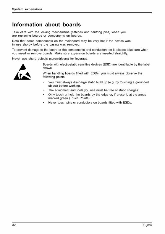
Information about boardsTake care with the locking mechanisms (catches and centring pins) when youare replacing boards or components on boards.
Note that some components on the mainboard may be very hot if the device wasin use shortly before the casing was removed.
To prevent damage to the board or the components and conductors on it, please take care whenyou insert or remove boards. Make sure expansion boards are inserted straightly.
Never use sharp objects (screwdrivers) for leverage.
Boards with electrostatic sensitive devices (ESD) are identifiable by the labelshown.
When handling boards fitted with ESDs, you must always observe thefollowing points:
• You must always discharge static build up (e.g. by touching a groundedobject) before working.
• The equipment and tools you use must be free of static charges.
• Only touch or hold the boards by the edge or, if present, at the areasmarked green (Touch Points).
• Never touch pins or conductors on boards fitted with ESDs.
32 Fujitsu
System expansions
Opening the casing
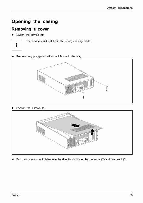
Removing a cover► Switch the device off.
The device must not be in the energy-saving mode!
► Remove any plugged-in wires which are in the way.
1
1
► Loosen the screws (1).
3
2
► Pull the cover a small distance in the direction indicated by the arrow (2) and remove it (3).
Fujitsu 33

System expansions
Removing the front panel
11
1
► Lift the locking lugs on the front panel (1).
2
► Fold the front panel in the direction of the arrow (2) and remove it from the casing.
34 Fujitsu

System expansions
Close the casing
Securing the front panel
1
a a a
► Place the front panel with the three lower hooks in the front lower guide openings on the casing.
► Fold the front panel in the direction of the arrow (1) until the catches (a) engage.
Fujitsu 35

System expansions
Reattaching the cover
1
2
► Place the cover on the casing (1) and push it into place in the direction indicated by the arrow (2).
1
1
► Fasten the screws (1).
► Connect the cables to the device.
36 Fujitsu

System expansions
Removing the drive carrierRemoving
► Open the casing (see "Opening the casing", Page 33).
► Remove the front panel from the casing (see "Removing the front panel", Page 34).
► If drives are installed, disconnect their data cable and power supply cable plugs.
1
2
a
a
a
a
► Slightly lift the drive cage using the plastic handle (1).
► Slide the drive cage in the direction of the arrow (2) until the guides (a) are thesame height as the corresponding openings in the casing.
3
► Use the plastic handle to lift the drive cage out of the casing (3).
Fujitsu 37
System expansions
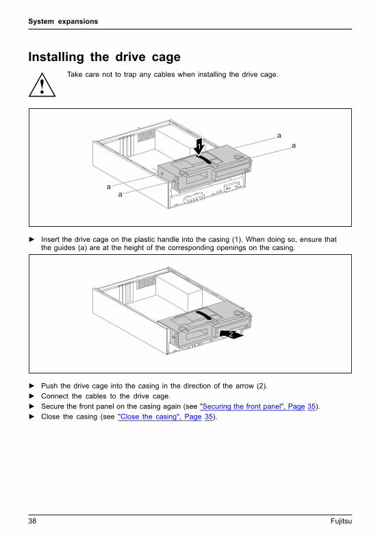
Installing the drive cageDrivecage
Take care not to trap any cables when installing the drive cage.
1
aa
aa
► Insert the drive cage on the plastic handle into the casing (1). When doing so, ensure thatthe guides (a) are at the height of the corresponding openings on the casing.
2
► Push the drive cage into the casing in the direction of the arrow (2).
► Connect the cables to the drive cage.
► Secure the front panel on the casing again (see "Securing the front panel", Page 35).
► Close the casing (see "Close the casing", Page 35).
38 Fujitsu

System expansions
Installing and removing drivesThe casing can accommodate a total of three drives:
• one accessible 5 1/4 inch drive
• an accessible or non-accessible 3 1/2 inch drive or 2 1/2 inch drive
• a non-accessible drive
"Accessible drives" are e.g. DVD or CD ROM drives, into which a data medium can be insertedfrom outside. "Non-accessible drives" are for example hard disk drives.
Removing and installing accessible drivesThe number of screws used to attach the drives varies according to the type ofdrive fitted and may not necessarily match the depiction below.
Fujitsu 39
System expansions
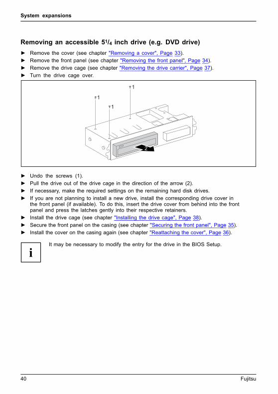
Removing an accessible 51/4 inch drive (e.g. DVD drive)
► Remove the cover (see chapter "Removing a cover", Page 33).
► Remove the front panel (see chapter "Removing the front panel", Page 34).
► Remove the drive cage (see chapter "Removing the drive carrier", Page 37).
► Turn the drive cage over.
2
1
1
1
► Undo the screws (1).
► Pull the drive out of the drive cage in the direction of the arrow (2).
► If necessary, make the required settings on the remaining hard disk drives.
► If you are not planning to install a new drive, install the corresponding drive cover inthe front panel (if available). To do this, insert the drive cover from behind into the frontpanel and press the latches gently into their respective retainers.
► Install the drive cage (see chapter "Installing the drive cage", Page 38).
► Secure the front panel on the casing (see chapter "Securing the front panel", Page 35).
► Install the cover on the casing again (see chapter "Reattaching the cover", Page 36).
It may be necessary to modify the entry for the drive in the BIOS Setup.
40 Fujitsu

System expansions
Installing an accessible 51/4 inch drive (e.g. DVD drive)
► Remove the cover (see chapter "Removing a cover", Page 33).
► Remove the front panel (see chapter "Removing the front panel", Page 34).
► Remove the drive cover if one is fitted. To do this, press the corresponding drive coverlightly out forwards and pull the drive cover forward out of the front panel.
Do not throw away the covers. If you remove the drive again, you must reinstall thecovers (cooling, fire protection or EMC regulations to be complied with).EMC,electromagneticcompatibility
► Remove the drive cage (see chapter "Removing the drive carrier", Page 37).
► Turn the drive cage over.
► Take the new drive out of its packaging.
1
2
2
2
► Slide the new drive into the drive cage (1). Make sure that the screw holesof the drive cage and of the drive are aligned.
► Fasten the screws (2).
► Install the drive cage (see chapter "Installing the drive cage", Page 38).
► Plug the data and the power supply connectors into the drive. Make sure the polarity is correct.
► Secure the front panel on the casing (see chapter "Securing the front panel", Page 35).
► Install the cover on the casing again (see chapter "Reattaching the cover", Page 36).
It may be necessary to modify the entry for the drive in the BIOS Setup.
Fujitsu 41

System expansions
Removing an accessible 31/2 inch drive (multicard reader) oran inaccessible 31/2 inch drive (hard disk)
► Remove the cover (see chapter "Removing a cover", Page 33).
► Remove the front panel (see chapter "Removing the front panel", Page 34).
► Remove the drive cage (see chapter "Removing the drive carrier", Page 37).
► Disconnect all cables connected to the drive (data cable, power supply cable).
► Turn the drive cage over.
2
1 11
► Remove the screws (1).
► Pull the drive out of the drive cage in the direction of the arrow (2).
► Install the drive cage (see chapter "Installing the drive cage", Page 38).
► Secure the front panel on the casing (see chapter "Securing the front panel", Page 35).
► Install the cover on the casing again (see chapter "Reattaching the cover", Page 36).
It may be necessary to modify the entry for the drive in the BIOS Setup.
42 Fujitsu

System expansions
Installing an accessible 31/2 inch drive (multicard reader) or ainaccessible 31/2 inch drive (hard disk)
► Remove the cover (see chapter "Removing a cover", Page 33).
► Remove the front panel (see chapter "Removing the front panel", Page 34).
► Remove the drive cover if one is fitted. To do this, press the corresponding drive coverlightly out forwards and pull the drive cover forward out of the front panel.
► Remove the drive cage (see chapter "Removing the drive carrier", Page 37).
► Turn the drive cage over.
1
2 22
► Slide the drive into the casing (1). Make sure that the screw holes of thedrive cage and of the drive are aligned.
► Fasten the drive into place with the screws (2).
► Install the drive cage (see chapter "Installing the drive cage", Page 38).
► Plug the data and the power supply connectors into the drive. Make sure the polarity is correct.
► Secure the front panel on the casing (see chapter "Securing the front panel", Page 35).
► Install the cover on the casing again (see chapter "Reattaching the cover", Page 36).
It may be necessary to modify the entry for the drive in the BIOS Setup.
Fujitsu 43
System expansions
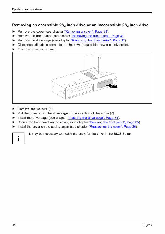
Removing an accessible 21/2 inch drive or an inaccessible 21/2 inch drive
► Remove the cover (see chapter "Removing a cover", Page 33).
► Remove the front panel (see chapter "Removing the front panel", Page 34).
► Remove the drive cage (see chapter "Removing the drive carrier", Page 37).
► Disconnect all cables connected to the drive (data cable, power supply cable).
► Turn the drive cage over.
11
1
2
► Remove the screws (1).
► Pull the drive out of the drive cage in the direction of the arrow (2).
► Install the drive cage (see chapter "Installing the drive cage", Page 38).
► Secure the front panel on the casing (see chapter "Securing the front panel", Page 35).
► Install the cover on the casing again (see chapter "Reattaching the cover", Page 36).
It may be necessary to modify the entry for the drive in the BIOS Setup.
44 Fujitsu

System expansions
Installing an accessible 21/2 inch drive or an inaccessible 21/2 inch drive
► Remove the cover (see chapter "Removing a cover", Page 33).
► Remove the front panel (see chapter "Removing the front panel", Page 34).
► Remove the drive cover if one is fitted. To do this, press the corresponding drive coverlightly out forwards and pull the drive cover forward out of the front panel.
► Remove the drive cage (see chapter "Removing the drive carrier", Page 37).
► Turn the drive cage over.
1
22
2
► Slide the drive into the casing (1). Make sure that the screw holes of the drive cage andof the drive are aligned. The screw positions are identified with "HDD 2.5”".
► Fasten the drive into place with the screws (2).
► Install the drive cage (see chapter "Installing the drive cage", Page 38).
► Plug the data and the power supply connectors into the drive. Make sure the polarity is correct.
► Secure the front panel on the casing (see chapter "Securing the front panel", Page 35).
► Install the cover on the casing again (see chapter "Reattaching the cover", Page 36).
It may be necessary to modify the entry for the drive in the BIOS Setup.
Fujitsu 45

System expansions
Removing a hard disk drive
Removing the hard disk drive cage
► Remove the cover (see chapter "Removing a cover", Page 33).
► Remove the front panel (see chapter "Removing the front panel", Page 34).
► Remove the drive cage (see chapter "Removing the drive carrier", Page 37).
► Disconnect the cables from the mainboard.
1
2
► Undo the screw (1).
► Take the hard disk drive cage out of the casing (2).
46 Fujitsu
System expansions
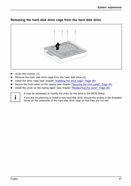
Releasing the hard disk drive cage from the hard disk drive
1 1 1 1
2
► Undo the screws (1).
► Remove the hard disk drive cage from the hard disk drive (2).
► Install the drive cage (see chapter "Installing the drive cage", Page 38).
► Secure the front panel on the casing (see chapter "Securing the front panel", Page 35).
► Install the cover on the casing again (see chapter "Reattaching the cover", Page 36).
It may be necessary to modify the entry for the drive in the BIOS Setup.
If you are not planning to install a new hard disk drive, secure the screws in the threadedbores on the underside of the hard disk drive cage so that they are not lost.
Fujitsu 47
System expansions
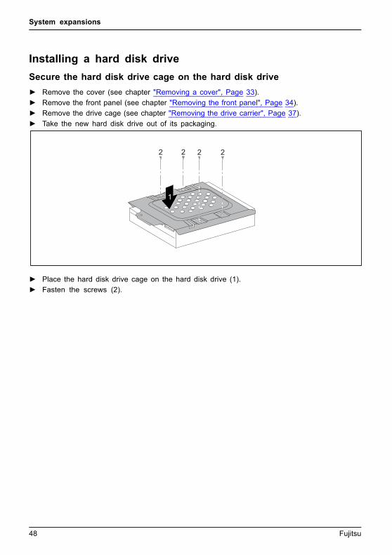
Installing a hard disk drive
Secure the hard disk drive cage on the hard disk drive
► Remove the cover (see chapter "Removing a cover", Page 33).
► Remove the front panel (see chapter "Removing the front panel", Page 34).
► Remove the drive cage (see chapter "Removing the drive carrier", Page 37).
► Take the new hard disk drive out of its packaging.
2 2 2 2
1
► Place the hard disk drive cage on the hard disk drive (1).
► Fasten the screws (2).
48 Fujitsu
System expansions
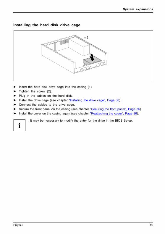
Installing the hard disk drive cage
2
1
► Insert the hard disk drive cage into the casing (1).
► Tighten the screw (2).
► Plug in the cables on the hard disk.
► Install the drive cage (see chapter "Installing the drive cage", Page 38).
► Connect the cables to the drive cage.
► Secure the front panel on the casing (see chapter "Securing the front panel", Page 35).
► Install the cover on the casing again (see chapter "Reattaching the cover", Page 36).
It may be necessary to modify the entry for the drive in the BIOS Setup.
Fujitsu 49

System expansions
Installing and removing heat sinks
Removing the heat sink► Remove the cover (see chapter "Removing a cover", Page 33).
► Disconnect the fan cables from the mainboard.
1
11
1
2
► Undo the screws (1).
► Remove the heat sink from the casing (2).
► Install the cover on the casing again (see chapter "Reattaching the cover", Page 36).
Installing the heat sink► Remove the cover (see chapter "Removing a cover", Page 33).
2
22
2
1
► Insert the heat sink into the casing (1).To do this, correctly align the screwholes on the heat sink with the screwholes on the mainboard.
► Fasten the screws (2).
► Connect the fan cables to the mainboard.
► Install the cover on the casing again (see chapter "Reattaching the cover", Page 36).
50 Fujitsu

System expansions
Assembling and dismantling low-profile unitsLow-profileboard
For every slot there is a slot cover provided. If no board is installed, the slot cover protects the slot.
When you install a board, do not discard the corresponding slot cover.
For cooling, protection against fire and in order to comply with EMC regulations,you must refit the slot cover if you remove the board.
Removing a slot cover► Open the casing (see "Opening the casing", Page 33).
1
2
► Undo the screw (1).
► Pull the slot cover out of the slot (2).
Fujitsu 51

System expansions
Installing a board
2
1
► Push the board into the slot (1)until it engages.
► Tighten the screw (2).
► If necessary, connect the cables to the board.
If you have installed or removed a board, please check the relevant PCIslot settings in the BIOS Setup. If necessary, change the settings. Furtherinformation is provided in the PCI board documentation.
Removing boards► If necessary, disconnect the cables which are connected to the board.
2
1
► Loosen the screw (1).
► Pull the board out of the slot (2).
► Place the board in suitable packaging.
52 Fujitsu

System expansions
Reinstalling a slot cover
2
1
► Push the slot cover into the slot (1).
► Tighten the screw (2).
► Close the casing (see "Close the casing", Page 35).
If you have installed or removed a board, please check the relevant PCIslot settings in the BIOS Setup. If necessary, change the settings. Furtherinformation is provided in the PCI board documentation.
Mainboard expansionsDetails on how to upgrade the main memory or the processor of your devicecan be found in the manual for the mainboard.UpgradesLithiumbatteryProcessorMainmemoryMainboard
Upgrading main memory► Open the casing (see "Opening the casing", Page 33).
Mainmemory,
► Upgrade the memory according to the description in the manual for the mainboard.
► Close the casing (see "Close the casing", Page 35).
Processor, replacing► Open the casing (see "Opening the casing", Page 33).
Processor,replacing
► Upgrade the processor according to the description in the manual for the mainboard.
► Close the casing (see "Close the casing", Page 35).
Fujitsu 53

System expansions
Replacing the lithium batteryIn order to permanently save the system information, a lithium battery is installed to providethe CMOS-memory with a current. A corresponding error message notifies the user when thecharge is too low or the battery is empty. The lithium battery must then be replaced.
Incorrect replacement of the lithium battery may lead to a risk of explosion!
The lithium battery may be replaced only with an identical battery or witha type recommended by the manufacturer.
Do not dispose of lithium batteries with household waste. They must be disposedof in accordance with local regulations concerning special waste.
Make sure that you observe the correct polarity when replacing the lithiumbattery. The plus pole must be on the top!Lithiumbattery,Replacing,Replacing,Replacing, lithiumbatteryBattery
The lithium battery holder exists in different designs that function in the same way.
12 3
1
23
► Press the catch in the direction of the arrow (1).
The battery jumps out of the holder slightly.
► Remove the battery (2).
► Push the new lithium battery of the identical type into the holder (3) andpress it down until it engages.
54 Fujitsu
Technical specification
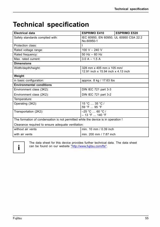
Technical specificationElectrical data ESPRIMO E410 ESPRIMO E520
Safety standards complied with: IEC 60950, EN 60950, UL 60950 CSA 22.2No.60950-1
Protection class: I
Rated voltage range: 100 V – 240 V
Rated frequency: 50 Hz – 60 Hz
Max. rated current: 3.0 A – 1.5 A
Dimensions
Width/depth/height: 328 mm x 405 mm x 105 mm/12.91 inch x 15.94 inch x 4.13 inch
Weight
in basic configuration: approx. 8 kg / 17.63 lbs
Environmental conditions
Environment class (3K2):
Environment class (2K2):
DIN IEC 721 part 3-3
DIN IEC 721 part 3-2
Temperature:
Operating (3K2): 15 °C .... 35 °C /59 °F ... 95 °F
Transportation (2K2): –25 °C .... 60 °C /– 13 °F ... 140 °F
The formation of condensation is not permitted while the device is in operation !
Clearance required to ensure adequate ventilation:
without air vents
with air vents
min. 10 mm / 0.39 inch
min. 200 mm / 7.87 inch
The data sheet for this device provides further technical data. The data sheetcan be found on our website "http://www.fujitsu.com/fts".
Fujitsu 55

Index
IndexAAlphanumeric keypad 24Anti-theft protection 26Audio input 19Audio output 19
BBattery 54BIOS Setup 25BIOS Setup,
configuration 25settings 25system settings 25
Button,ON/OFF switch 24
CCable,
connecting 18disconnecting 18
Casing,lead-sealing 26
CE marking 9Chain 26Components
installing/removing 31Connecting a PS/2 keyboard 20Connecting,
keyboard 20mouse 20PS/2 keyboard 20PS/2 mouse 20USB keyboard 20
Contents of delivery 13Cord
see Cable 18Ctrl+Alt+Del 25Cursor keys 24
DData protection 26Device
indicators 23Device drivers,
serial interface 21Device,
anti-theft protection 26lead-sealing 26
ports 19setting up 14switching off 22switching on 22transporting 7–8upgrades 31
Devices,connecting 21
Disposal 8Drive cage
installing 38Drivers & Utilities DVD 8
EElectromagnetic compatibility 9EMC, electromagnetic compatibility 41Energy saving 8Ergonomic
video workstation 14External devices,
connecting 21ports 19
FFunction keys 24
GGetting started 13
HHeadphones 19
IImportant notes 7Indicators,
device 23Installing,
software 16–17switching on for the first time 16
Interfaces 19
KKeyboard 24Keyboard port 19keyboard shortcuts 25Keyboard shortcuts 24
56 Fujitsu
Index
Keyboard,alphanumeric keypad 24connecting 20cursor keys 24function keys 24numeric keypad 24port 20
Keys 24Ctrl 25Ctrl+Alt+Del 25Menu key 25
Keys,Alt Gr 25Control 25Ctrl key 25cursor keys 24Enter 24Enter key 24menu key 25Num Lock 25Return 24shift 25shift key 25Start key 25
LLAN port 19Lead-sealing 26Line in 19Line out 19Lithium battery 53Lithium battery,
replacing 54Low voltage directive 9Low-profile board 51
MMain memory 53Main memory,
upgrading 53Mainboard
Upgrades 53Mains adapter
connecting 15Microphone port 19Monitor
connecting 19Monitor port 19Monitor,
switching off 22switching on 22
Mouse port 19
Mouse,connecting 20
NNote
safety 7Notes
CE marking 9important 7
Numeric keypad 24
OON/OFF switch 24Overview
Device 5
PPackaging 13Packaging,
unpacking 13Ports 11Preparing for first use, overview 13Preparing for use,
overview 13Processor 53Processor, replacing 53Property protection 26PS/2 mouse port 19PS/2 mouse,
connecting 20port 20
RRecycling 8Removing
the drive carrier 37Replacing,
lithium battery 54Replacing, lithium battery 54Retransportation 7–8
SSafety information 7Security Lock 26Security measures 26Serial interface 19, 21Serial interface,
connecting devices 21settings 21
Servicing 31
Fujitsu 57
Index
Setup,see BIOS Setup 25
Software,installing 16–17
System expansion 31System settings,
BIOS Setup 25System unit, see Device 8
TTransportation 7–8
UUniversal Serial Bus 19Upgrades
Mainboard 53Upgrades,
device 31USB devices,
connecting 21USB port 20USB port,
connecting devices 21connecting keyboard 20connecting the mouse 20
User Documentation DVD 8
VVideo workstation 14
58 Fujitsu


