R2D2 ESR-LCR METER DESCRIPTION. The device is designed for measuring low resistance, inductance, capacitance and ESR of capacitors. Functionally, the circuit can be divided into eight modules: 1. L / C oscillator 2. Block stable current sources (50mA/5mA/0.5mA) 3. Unit responsible for the discharge of the capacitor test 4. Block voltage amplifier 5. Block display (Nokia LCD 3310) 6. control buttons 7. PIC18F2520 microcontroller 8. Switch (for switching components of the subjects) The principle of the LC oscillator and therefore the principle of measuring the inductance and capacitance (1p - 1uF) to describe in detail not see the point. This is detailed in the descriptions of similar devices to whom the Internet weight. I will mention only some features that were used in this scheme and algorithm of calculation. To measure the inductance and capacitance using different pairs of probes ... This approach has allowed more accurate measurements to establish a permanent, automatic, partial calibration. Ie LC oscillator frequency drift does not have such a significant impact on the accuracy measurement as it was before. Also, a new approach to calculation has allowed to get rid of the influence of interturn capacitance measured inductance in the measurement (it is taken into account during calibration). Measurement of capacitance of electrolytic capacitors is organized by the classical method - a charge the capacitor stable current source to a certain level of voltage (0,2 v) with a parallel counting the charging time. The scheme is implemented seq. way. Capacitor connected subject pre-
Transcript
R2D2 ESR-LCR METER DESCRIPTION.
The device is designed for measuring low resistance, inductance, capacitance and ESR of capacitors. Functionally, the circuit can be divided into eight modules:
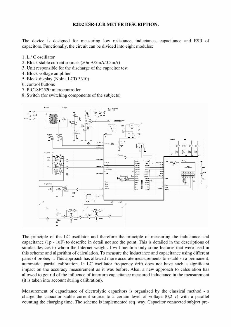
1. L / C oscillator2. Block stable current sources (50mA/5mA/0.5mA)3. Unit responsible for the discharge of the capacitor test4. Block voltage amplifier5. Block display (Nokia LCD 3310)6. control buttons7. PIC18F2520 microcontroller8. Switch (for switching components of the subjects)
The principle of the LC oscillator and therefore the principle of measuring the inductance and capacitance (1p - 1uF) to describe in detail not see the point. This is detailed in the descriptions of similar devices to whom the Internet weight. I will mention only some features that were used in this scheme and algorithm of calculation. To measure the inductance and capacitance using different pairs of probes ... This approach has allowed more accurate measurements to establish a permanent, automatic, partial calibration. Ie LC oscillator frequency drift does not have such a significant impact on the accuracy measurement as it was before. Also, a new approach to calculation has allowed to get rid of the influence of interturn capacitance measured inductance in the measurement (it is taken into account during calibration). Measurement of capacitance of electrolytic capacitors is organized by the classical method - a charge the capacitor stable current source to a certain level of voltage (0,2 v) with a parallel counting the charging time. The scheme is implemented seq. way. Capacitor connected subject pre-
discharge (Q1) and then fed it to a stable voltage and the timer countdown. At the moment of reaching the voltage level of 0,2 v. triggers an internal comparator and a fixed timer. Next is the capacitance calculation. To reduce the measurement time you can select the maximum limit of measuring the capacitance of the test capacitor (100/300/600 thousands of microfarads). Measurement of ESR (ESR) capacitor and the measurement of low resistances is performed by ff. principle. On the subject capacitor short voltage pulse is applied formed a stable source of supply. This causes a spike in voltage magnitude is proportional to the ESR of the capacitor. Two series-connected DU increase the signal to the required level. Further, connected to the output of op amp microcontroller registers peak of the pulse and performs the analog-digital transformation for further calculation of voltage. Knowing the value of the current pulse and the voltage produced calculation of ESR.When measuring the ESR of small vessels (<10uF) is a slight overstatement of meter readings. Despite the fact that pulse duration of 1-2uS enough to recharge the capacitor had a little, thus slightly overestimated the value of the measured voltage.
Construction details.
Some design features that should be considered when repeated. Trimmer to block the source stable current (2. I_source) should be replaced by the constant, after selecting their approximate value in the configuration process (Described below).
Trimmer resistors R3 and R8 in the amplifier unit (4. Amp) is recommended to use multi. This will allow fine-tuning of the coefficients. enhance the value of which depends on the accuracy of the instrument (especially critical for ESR).Instead of two MCP601 op amp can be used one MCP602.Relay in switching unit (8. Switch) must be used bistable with two windings rated for 5v.Capacitors C2 and C5-polar tantalum or "pottery." Choke L1 - such as "dumbbells". Even better, if the "dumbbells" will be in the ferrite "glass".Block "S1 optional" is the control unit supply voltage on the LC oscillator. Optionally, there is a possibility turn off the generator in the measurement mode "elektorlitov" scheme to reduce power consumption. S1 unit can not use, simply plug the generator to the LC diet.! To avoid failure of the microcontroller, Jmp jumper should be set only after the voltage setting inpoint "B" resistor "R_Vbat" (described below).The circuit module is missing frequency (prescaler and buffer), although the software itself is implemented frequency. Measured frequency (with the "correct" amplitude) must be submitted by 6 output MK (F). It should be understood that for modes measuring capacitance and inductance at input 6 MK must be supplied from the output signal LC oscillator. With this purpose in the scheme shows the switch. One of the possible solutions of the schematic module frequency (prescaler / buffer switching) is still under development. If necessary, switching can be arranged on the commonswitches, as well as diagrams of the input circuits (divider \ buffer) using one of the many schemes available in Internet.
Setting up and operating the device.
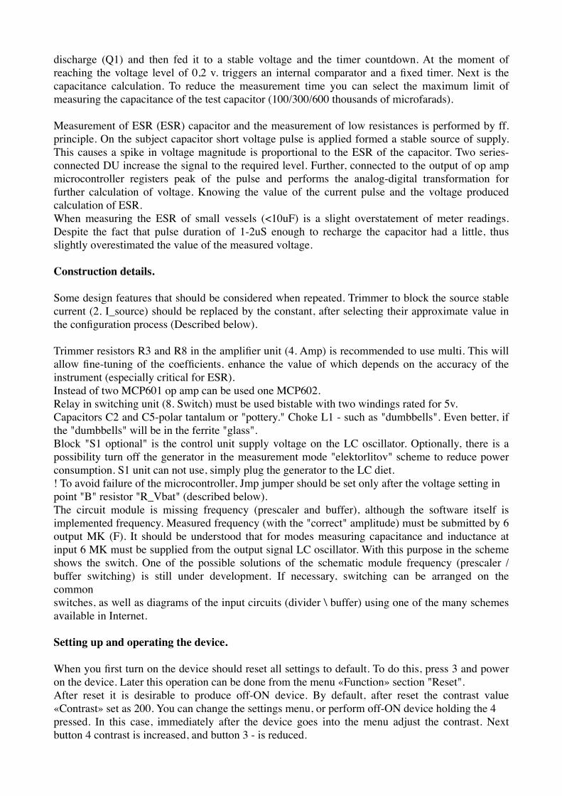
When you first turn on the device should reset all settings to default. To do this, press 3 and power on the device. Later this operation can be done from the menu «Function» section "Reset".After reset it is desirable to produce off-ON device. By default, after reset the contrast value «Contrast» set as 200. You can change the settings menu, or perform off-ON device holding the 4pressed. In this case, immediately after the device goes into the menu adjust the contrast. Next button 4 contrast is increased, and button 3 - is reduced.
The accuracy of the measurement accuracy is significantly affected by the settings of stable sources of supply. To configure must go to the menu «Function» and then select the section "I_50" button «OK». Then connect to the terminals of measuring C / ESR milliammeter. Milliammeter will show the current value of future momentum for measuring ESR.C using trimmer (R3) to install the current as close as possible to the value of 50mA. Thereafterremember reading on and off milliammeter. Next, using the + / - to set the value of the device menureflected by earlier milliammeter within a tenth and save it by clicking OK.The same procedure must be run to power source 5 and sections 0,5 mA ... "I_5" and "I_05", adjusting the current subscript corresponding resistors, with the measured value should be inserted in the device menu with to two decimal places / thousandths.It is important to remember that switching between sections should be done with disconnected milliammeter. Later recommended to replace the trimmer with the constant and repeat the setup process.
Setting up the OS.
The process of configuring the OS is reduced to tuning gain K of each OU to the value specified in sections and Amp1 Amp2. for this select the measurement mode ESR / C / R and beyond:
1. Connect to terminals electrolyte knowingly capacity (better to take a small capacitor with a capacity of 10 - 50uF) and with the resistor R3 and postroechnogo variable Amp1 (~ 6.0) in the setup menu, make appropriate indications on the screen.
2. Then connect to the terminals of known resistance (preferably 1 - 10 ohms) and with the help of resistor R8 and postroechnogo variable Amp2 (~ 6.0) in the setup menu, make appropriate indications on the screen.On the accuracy of the measurement of resistance will affect the accuracy of setting the current tocurrent Sources0.00 -1.00 Om - section "I_50"1.00 -10.0 Om - section "I_5"10.0 -100 Om - section "I_05"
Setting LC oscillator.
Setting LC oscillator is reduced to the selection of inductor L1 and capacitor C1 so that the oscillator frequency, which can be controlled by the regime "Oscillator" was in the range 900kGts. C2 and C5 should be tantalum or nonpolar "ceramics." Calibration capacitor can be anything in the range of 500-1200 pF. The main thing that it was capacitor with a minimum of TKE and a known value of your container. Very well, if it is possible to pre-to measure its real capacity to some calibrated meter. The value of the total capacity C_cal and C3 should be recorded in the section "6.Ccal". C3 can not install (.... spied in a similar decision, as an option reducing the total TKE).Battery indicator.Display Setting the charge is reduced to the installation at the point "B" voltage equal to about one third the battery voltage supply. For it is necessary to measure the battery voltage supply at a point "A" (when the device) U1. Then connect the voltmeter in point "B" achieved by adjusting the resistor «R_Vbat» voltmeter U2 equal to about 1 / 3 of U1. Further to calculate the division factor K_div = U1/U2 and write values to the relevant sections in the menu settings. Also indicatein setting the voltage with a fully charged battery "V_bat" and minimum battery voltage in which the device will signal the need to replace / recharge the battery.Also, to improve the accuracy of the ADC is desirable to specify the exact menu voltage microcontroller V_ref (on default is 5v) measured it when the device at V_ref.
Measurement of ESR / C / R (from 0.1 - 600 000 uF)
To measure the need to:1. Enable device (terminals for measuring component-free)2. Switch the device by pressing the "Mode" (hereinafter M) mode ESR / C / R3. If necessary, perform a calibration (see below)4. Connect the measurement component to the terminals (C)5. The device's screen displays the measurement result.It should be noted that the speed of measurement affects the measured capacitance of the capacitor. Maximum limit measurements can be selected in the menu «Function» (C_max) (stated in thousands of microfarads) Calibration mode ESR / C / R.
Calibration is to compensate for the effect of the length of wires Clem and others on the measurement of internal resistance. For calibration must be in the mode ESR / C / R button «Calibration» (hereinafter C). When the menu «Close probes» (closed probes) should be close to the device probes the countdown on the screen. After perform the calibration, configuration information is automatically stored in nonvolatile memory device, which will not subsequently be calibrated each time you turn on your device.
Measure C (C <1uF)
To measure the need to:1. Enable device (terminals for measuring component-free)2. Switch the device by pressing the "M" mode in C-meter3. If necessary, perform a calibration (see below)4. Connect the measurement component to the terminals5. The device's screen displays the measurement result. Calibration in C mode
Calibration is to compensate for the effect of the length of wires Clem and others in the measurement capacitor. For calibration must be in mode C (measuring the component connection terminals are open, measured capacitor is disconnected) and press the button "C". Measure L
To measure the need to:1. Enable device (terminals for measuring component-free)2. Switch the device by pressing the "M" mode in L-meter3. If necessary, perform a calibration (see below)4. Connect the measurement component to the terminals5. The device's screen displays the measurement result.6. When measuring the inductance (especially the small denominations) for higher accuracy can bemeasurement process (without disabling the measured inductance) to calibrate the touch of a button "C". At the same time The device is calibrated and the display will reflect the importance attached inductance as close to real.
Calibration mode L
Calibration is to compensate for the effect of the length of wires Clem and others on the measurement of inductance.There are two types of calibration - 'deep' to calculate the inductance of the probe and the "usual" to correct the drift of the generator.Regular calibration is performed by pressing the "C" in the mode of L-meter. Calibration can be performed with a connected measured inductance to schupam device.To perform a "deep" calibration, you must click the "C" and keep it pressed until you see signs«Close probes and take away hand» (closed probes and clean hands) and then close the test leads to the end of the reverse reference on the screen, remove your hands and wait for the calibration process. After calibration, unlock probes.Deep calibration can not be conducted continuously since after the "deep" calibration value of inductance Probe connections are stored in volatile memory of microprocessor. Measure F
To measure the frequency needed:1. Insert the device2. Switch the device by pressing the "M" mode in F-meter3. Select the mode (with or without prescaler) using the "/"4. Submit the measured frequency of the input of the «F» (6th output MC). Change prescaler division factor applied by using the button «K». After installation of the coefficient to preserve the "OK button" value will be stored in nonvolatile memory.
Diagram of the device does not contain modules of the frequency (prescaler and buffer). Beep "Reminder"
If the measurements are not carried out more than ~ 1 minute, the device begins to publish an intermittent beep. Further signal repeats every ~ 20 seconds.Beep "reminder" will not be included, if the instrument is set to "Off".
translation by Kripton2035 (and google...) on october 2011