44
© 2000 Cisco Systems, Inc. 14-1 Establishing a Frame Relay PVC Connection

© 2000 Cisco Systems, Inc. 14-1
Establishing a Frame Relay PVC Connection

© 2000, Cisco Systems, Inc. www.cisco.com ICND v1.0a—14-2
• Determine how Frame Relay operates
• Configure Frame Relay
• Configure Frame Relay subinterfaces
• Verify Frame Relay operation
Objectives
Upon completion of this chapter, you willbe able to perform the following tasks:

© 2000, Cisco Systems, Inc. www.cisco.com ICND v1.0a—14-3
Frame Relay Overview Frame Relay Overview
?Way of sending information over a wide area network (WAN)?Divides the information into frames or packets.?Each frame has an address that the network uses to determine the destination of the frame.

© 2000, Cisco Systems, Inc. www.cisco.com ICND v1.0a—14-4
Frame Relay Features Frame Relay Features
?Increased Speeds
?Dynamic Bandwidth
?Smarter Attached Devices
?Higher Performance
?Low Overhead / High Reliability

© 2000, Cisco Systems, Inc. www.cisco.com ICND v1.0a—14-5
Frame Relay DevicesFrame Relay Devices
A frame relay network consists of endpoints, frame relay access network devices (e.g., bridges, routers, hosts, frame relay access devices switches, network routers, T1/E1multiplexers). These devices fall into two different categories: ?DTE: Data Terminating Equipment ?DCE: Data Communication Equipment

© 2000, Cisco Systems, Inc. www.cisco.com ICND v1.0a—14-6
Frame Relay Network Frame Relay Network
A frame relay network will often be depicted as a network cloud
Frame relay network is not a single physical connection between endpoints. Logical paths are defined within the network. Based on the concept of using virtual circuits (VCs).

© 2000, Cisco Systems, Inc. www.cisco.com ICND v1.0a—14-7
Virtual CircuitsVirtual Circuits
VCs are two-way, software-defined data paths between two ports that act as private line replacements in the network.There are two types of virtual circuits: Switched Virtual Circuits Permanent Virtual Circuits

© 2000, Cisco Systems, Inc. www.cisco.com ICND v1.0a—14-8
Switched Virtual CircuitsSwitched Virtual Circuits
The Four States of SVC
? Call setup
? Data transfer
? Idling
? Call termination

© 2000, Cisco Systems, Inc. www.cisco.com ICND v1.0a—14-9
Call SetupCall Setup
Call Setup: In this initial state, the virtual circuit between two Frame Relay DTE devices is established.

© 2000, Cisco Systems, Inc. www.cisco.com ICND v1.0a—14-10
Data TransferData Transfer
Data Transfer: Next, data is transmitted between the DTE devices over the virtual circuit.

© 2000, Cisco Systems, Inc. www.cisco.com ICND v1.0a—14-11
IdlingIdling
Idling: In the idling stage, the connection is still open, but the data transfer has ceased.
© 2000, Cisco Systems, Inc. www.cisco.com ICND v1.0a—14-12
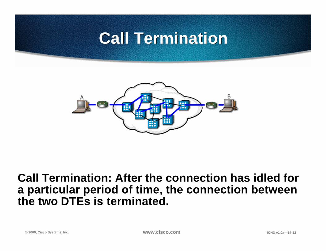
Call TerminationCall Termination
Call Termination: After the connection has idled for a particular period of time, the connection between the two DTEs is terminated.

© 2000, Cisco Systems, Inc. www.cisco.com ICND v1.0a—14-13
Permanent Virtual Circuits Permanent Virtual Circuits
?PVCs are fixed paths.
?PVC is like a dedicated point-to-point circuit.
?PVCs are popular because they provide a cost-effective alternative to leased lines.
There are only two states PVC:
?Data transfer
?Idling

© 2000, Cisco Systems, Inc. www.cisco.com ICND v1.0a—14-14
Frame Relay Frame Structure Frame Relay Frame Structure
Frame relay frame, user data packets are not changed in any way. Frame relay simply adds a two-byte header to the packets.

© 2000, Cisco Systems, Inc. www.cisco.com ICND v1.0a—14-15
Frame Relay
• Virtual circuits make connections• Connection-oriented service
Frame Relay works here.
DCE or FrameRelay Switch
CSU/DSU

© 2000, Cisco Systems, Inc. www.cisco.com ICND v1.0a—14-16
Frame Relay StackFrame Relay Stack
OSI Reference Model Frame Relay
Physical
Presentation
Session
Transport
Network
Data Link
Application
EIA/TIA-232, EIA/TIA-449, V.35, X.21, EIA/TIA-530
Frame Relay
IP/IPX/AppleTalk, etc.

© 2000, Cisco Systems, Inc. www.cisco.com ICND v1.0a—14-17
Frame Relay Terminology
LocalAccess
Loop=T1
Local AccessLoop=64 kbps
Local AccessLoop=64 kbps
DLCI: 400
PVC
DLCI: 500
LMI100=Active400=Active
LMI100=Active400=Active
DLCI: 200
DLCI: 100PVC

© 2000, Cisco Systems, Inc. www.cisco.com ICND v1.0a—14-18
CSU/DSU
Frame Relay Address Mapping
• Get locally significant DLCIs from provider • Map your network addresses to DLCIs
DLCI: 500 PVC 10.1.1.1
Inverse ARP orFrame Relay map
IP(10.1.1.1)
FrameRelay DLCI (500)

© 2000, Cisco Systems, Inc. www.cisco.com ICND v1.0a—14-19
Frame Relay Signaling
Cisco supports three LMI standards:• Cisco• ANSI T1.617 Annex D• ITU-T Q.933 Annex A
DLCI: 400PVC
Keepalive
CSU/DSU
DLCI: 500 PVC 10.1.1.1
xLMI500=Active400=Inactive
LMI500=Active400=Inactive

© 2000, Cisco Systems, Inc. www.cisco.com ICND v1.0a—14-20
Frame Relay Inverse ARP and LMI Operation
Frame RelayCloud
1
DLCI=100 DLCI=400
172.168.5.5 172.168.5.7

© 2000, Cisco Systems, Inc. www.cisco.com ICND v1.0a—14-21
Frame Relay Inverse ARP and LMI Operation
2 Status Inquiry 2Status Inquiry
Frame RelayCloud
1
DLCI=100 DLCI=400
172.168.5.5 172.168.5.7

© 2000, Cisco Systems, Inc. www.cisco.com ICND v1.0a—14-22
Frame Relay Inverse ARP and LMI Operation
3Local DLCI 100=Active
4Local DLCI 400=Active
2 Status Inquiry 2Status Inquiry
Frame RelayCloud
1
DLCI=100 DLCI=400
3
172.168.5.5 172.168.5.7

© 2000, Cisco Systems, Inc. www.cisco.com ICND v1.0a—14-23
Frame Relay Inverse ARP and LMI Operation
4Hello, I am 172.168.5.5.
3Local DLCI 100=Active
4Local DLCI 400=Active
2 Status Inquiry 2Status Inquiry
Frame RelayCloud
1
DLCI=100 DLCI=400
3
172.168.5.5 172.168.5.7
© 2000, Cisco Systems, Inc. www.cisco.com ICND v1.0a—14-24
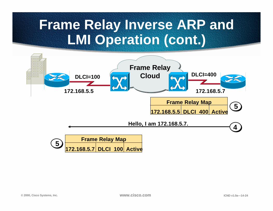
Frame Relay Inverse ARP and LMI Operation (cont.)
Hello, I am 172.168.5.7. 4
5Frame Relay Map
172.168.5.5 DLCI 400 Active
Frame RelayCloudDLCI=100 DLCI=400
Frame Relay Map
172.168.5.7 DLCI 100 Active5
172.168.5.5 172.168.5.7

© 2000, Cisco Systems, Inc. www.cisco.com ICND v1.0a—14-25
Frame Relay Inverse ARP and LMI Operation (cont.)
Hello, I am 172.168.5.7. 4
5Frame Relay Map
172.168.5.5 DLCI 400 Active
Frame RelayCloudDLCI=100 DLCI=400
Frame Relay Map
172.168.5.7 DLCI 100 Active5
Hello, I am 172.168.5.5.6
172.168.5.5 172.168.5.7
© 2000, Cisco Systems, Inc. www.cisco.com ICND v1.0a—14-26
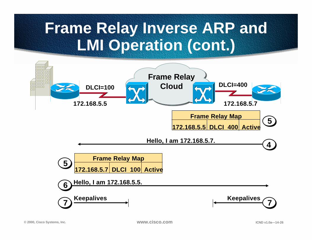
Frame Relay Inverse ARP and LMI Operation (cont.)
Keepalives Keepalives
Hello, I am 172.168.5.7. 4
5Frame Relay Map
172.168.5.5 DLCI 400 Active
Frame RelayCloudDLCI=100 DLCI=400
Frame Relay Map
172.168.5.7 DLCI 100 Active5
Hello, I am 172.168.5.5.6
7 7
172.168.5.5 172.168.5.7

© 2000, Cisco Systems, Inc. www.cisco.com ICND v1.0a—14-27
Rel. 11.2 Router Rel. 10.3 Router
interface Serial1ip address 10.16.0.1 255.255.255.0encapsulation frame-relaybandwidth 64
interface Serial1ip address 10.16.0.2 255.255.255.0encapsulation frame-relaybandwidth 64frame-relay lmi-type ansi
HQ Branch
Configuring Basic Frame Relay
Configuring Basic Frame Relay

© 2000, Cisco Systems, Inc. www.cisco.com ICND v1.0a—14-28
Inverse ARP• Enabled by default• Does not appear in configuration output
Rel. 11.2 Router Rel. 10.3 Router
HQ
interface Serial1ip address 10.16.0.1 255.255.255.0encapsulation frame-relaybandwidth 64
interface Serial1ip address 10.16.0.2 255.255.255.0encapsulation frame-relaybandwidth 64frame-relay lmi-type ansi
Branch
Configuring Basic Frame Relay (cont.)
Configuring Basic Frame Relay (cont.)

© 2000, Cisco Systems, Inc. www.cisco.com ICND v1.0a—14-29
DLCI=110IP address=10.16.0.1/24
p1r1
DLCI=100IP address=10.16.0.2/24
interface Serial1ip address 10.16.0.1 255.255.255.0encapsulation frame-relaybandwidth 64frame-relay map ip 10.16.0.2 110 broadcast
HQ Branch
Configuring a Static Frame Relay Map
Configuring a Static Frame Relay Map

© 2000, Cisco Systems, Inc. www.cisco.com ICND v1.0a—14-30
Verifying Frame Relay Operation
• Displays line, protocol, DLCI, and LMI information
Router#show interface s0Serial0 is up, line protocol is upHardware is HD64570Internet address is 10.140.1.2/24MTU 1500 bytes, BW 1544 Kbit, DLY 20000 usec, rely 255/255, load 1/255Encapsulation FRAME-RELAY, loopback not set, keepalive set (10 sec)LMI enq sent 19, LMI stat recvd 20, LMI upd recvd 0, DTE LMI upLMI enq recvd 0, LMI stat sent 0, LMI upd sent 0LMI DLCI 1023 LMI type is CISCO frame relay DTEFR SVC disabled, LAPF state downBroadcast queue 0/64, broadcasts sent/dropped 8/0, interface broadcasts 5Last input 00:00:02, output 00:00:02, output hang neverLast clearing of "show interface" counters neverQueueing strategy: fifoOutput queue 0/40, 0 drops; input queue 0/75, 0 drops<Output omitted>

© 2000, Cisco Systems, Inc. www.cisco.com ICND v1.0a—14-31
• Displays LMI information
Router#show frame-relay lmi
LMI Statistics for interface Serial0 (Frame Relay DTE) LMI TYPE = CISCOInvalid Unnumbered info 0 Invalid Prot Disc 0Invalid dummy Call Ref 0 Invalid Msg Type 0Invalid Status Message 0 Invalid Lock Shift 0Invalid Information ID 0 Invalid Report IE Len 0Invalid Report Request 0 Invalid Keep IE Len 0Num Status Enq. Sent 113100 Num Status msgs Rcvd 113100Num Update Status Rcvd 0 Num Status Timeouts 0
Verifying Frame Relay Operation (cont.)
Verifying Frame Relay Operation (cont.)

© 2000, Cisco Systems, Inc. www.cisco.com ICND v1.0a—14-32
• Displays PVC traffic statistics
Verifying Frame Relay Operation (cont.)
Verifying Frame Relay Operation (cont.)
Router#show frame-relay pvc 100
PVC Statistics for interface Serial0 (Frame Relay DTE)
DLCI = 100, DLCI USAGE = LOCAL, PVC STATUS = ACTIVE, INTERFACE = Serial0
input pkts 28 output pkts 10 in bytes 8398out bytes 1198 dropped pkts 0 in FECN pkts 0in BECN pkts 0 out FECN pkts 0 out BECN pkts 0in DE pkts 0 out DE pkts 0out bcast pkts 10 out bcast bytes 1198pvc create time 00:03:46, last time pvc status changed 00:03:47

© 2000, Cisco Systems, Inc. www.cisco.com ICND v1.0a—14-33
• Displays the route maps, either static or dynamic
Router#show frame-relay mapSerial0 (up): ip 10.140.1.1 dlci 100(0x64,0x1840), dynamic,
broadcast,, status defined, active
Verifying Frame Relay Operation (cont.)
Verifying Frame Relay Operation (cont.)

© 2000, Cisco Systems, Inc. www.cisco.com ICND v1.0a—14-34
• Clears dynamically created Frame Relay maps
Verifying Frame Relay Operation (cont.)
Verifying Frame Relay Operation (cont.)
Router#show frame-relay mapSerial0 (up): ip 10.140.1.1 dlci 100(0x64,0x1840), dynamic,
broadcast,, status defined, activeRouter#clear frame-relay-inarpRouter#sh frame mapRouter#

© 2000, Cisco Systems, Inc. www.cisco.com ICND v1.0a—14-35
• Displays LMI debug information
Verifying Frame Relay Operation (cont.)
Verifying Frame Relay Operation (cont.)
Router#debug Frame lmiFrame Relay LMI debugging is onDisplaying all Frame Relay LMI dataRouter#1w2d: Serial0(out): StEnq, myseq 140, yourseen 139, DTE up1w2d: datagramstart = 0xE008EC, datagramsize = 131w2d: FR encap = 0xFCF103091w2d: 00 75 01 01 01 03 02 8C 8B1w2d:1w2d: Serial0(in): Status, myseq 1401w2d: RT IE 1, length 1, type 11w2d: KA IE 3, length 2, yourseq 140, myseq 1401w2d: Serial0(out): StEnq, myseq 141, yourseen 140, DTE up1w2d: datagramstart = 0xE008EC, datagramsize = 131w2d: FR encap = 0xFCF103091w2d: 00 75 01 01 01 03 02 8D 8C1w2d:1w2d: Serial0(in): Status, myseq 1421w2d: RT IE 1, length 1, type 01w2d: KA IE 3, length 2, yourseq 142, myseq 1421w2d: PVC IE 0x7 , length 0x6 , dlci 100, status 0x2 , bw 0

© 2000, Cisco Systems, Inc. www.cisco.com ICND v1.0a—14-36
Star (Hub and Spoke)
Full Mesh
Partial Mesh
Frame Relay default: nonbroadcast, multiaccess (NBMA)
Selecting a Frame Relay Topology
Selecting a Frame Relay Topology

© 2000, Cisco Systems, Inc. www.cisco.com ICND v1.0a—14-37
Problem: Broadcast traffic must be replicated for each active connection
RoutingUpdate
A C
B
2
3
1
Reachability Issues with Routing Updates
Reachability Issues with Routing Updates
B
C
D
A

© 2000, Cisco Systems, Inc. www.cisco.com ICND v1.0a—14-38
Resolving Reachability Issues
Solution:• Split horizon can cause problems in NBMA environments
• Subinterfaces can resolve split horizon issues
• A single physical interface simulates multiple logical interfaces
Subnet A
Subnet B
Subnet C
S0
PhysicalInterface
S0.1S0.2S0.3
Logical Interface

© 2000, Cisco Systems, Inc. www.cisco.com ICND v1.0a—14-39
Configuring Subinterfaces
• Point-to-Point– Subinterfaces act as leased line – Each point-to-point subinterface requires its own
subnet
– Applicable to hub and spoke topologies
• Multipoint– Subinterfaces act as NBMA network so they do not
resolve the split horizon issue– Can save address space because uses single subnet– Applicable to partial-mesh and full-mesh topology

© 2000, Cisco Systems, Inc. www.cisco.com ICND v1.0a—14-40
A
10.17.0.1s0.2
B
Configuring Point-to-Point Subinterfaces
Configuring Point-to-Point Subinterfaces
interface Serial0no ip addressencapsulation frame-relay!interface Serial0.2 point-to-pointip address 10.17.0.1 255.255.255.0bandwidth 64frame-relay interface-dlci 110!interface Serial0.3 point-to-pointip address 10.18.0.1 255.255.255.0bandwidth 64frame-relay interface-dlci 120!
s0.310.18.0.1
C
10.17.0.2
10.18.0.2
DLCI=110
DLCI=120

© 2000, Cisco Systems, Inc. www.cisco.com ICND v1.0a—14-41
interface Serial2no ip addressencapsulation frame-relay
!interface Serial2.2 multipointip address 10.17.0.1 255.255.255.0bandwidth 64frame-relay map ip 10.17.0.2 120 broadcastframe-relay map ip 10.17.0.3 130 broadcastframe-relay map ip 10.17.0.4 140 broadcast
s2.1=10.17.0.2/24s2.2=10.17.0.1/24
s2.1=10.17.0.4/24
s2.1=10.17.0.3/24
RTR1
B
RTR3
RTR4
Multipoint Subinterfaces Configuration Example
Multipoint Subinterfaces Configuration Example
DLCI=120
DLCI=130
DLCI=140

© 2000, Cisco Systems, Inc. www.cisco.com ICND v1.0a—14-42
Visual ObjectiveVisual Objective
pod ro’s s0A 10.140.1.2B 10.140.2.2C 10.140.3.2D 10.140.4.2E 10.140.5.2F 10.140.6.2G 10.140.7.2H 10.140.8.2I 10.140.9.2J 10.140.10.2K 10.140.11.2L 10.140.12.2
core_ server10.1.1.1
wg_sw_a10.2.2.11
wg_sw_l10.13.13.11
wg_pc_a10.2.2.12
wg_pc_l10.13.13.12
wg_ro_ae0/1 e0/2
e0/2e0/1
e0
e0
fa0/23
core_sw_a10.1.1.2
wg_ro_l
core_ro10.1.1.3
fa0/24 fa0/0
FR
...
10.13.13.3
PPP with CHAP
Frame Relay
10.2.2.3s010.140.1.2/24
s010.140.12.2/24
s2/7.x10.140.1.1/24 … 10.140.12.1/24

© 2000, Cisco Systems, Inc. www.cisco.com ICND v1.0a—14-43
• Configure a Frame Relay PVC on a serial interface
• Configure Frame Relay subinterfaces
• Verify Frame Relay operation with show commands
Summary
After completing this chapter, you shouldbe able to perform the following tasks:
© 2000, Cisco Systems, Inc. www.cisco.com ICND v1.0a—14-44
1. What is a DLCI?
2. What are two methods to map a network layer address to a DLCI on a Cisco router?
3. What are the advantages of configuring Frame Relay subinterfaces?
Review QuestionsReview Questions


