Establishing the Technical Basis for Disposal of Heat-Generating Waste in Salt Prepared for U.S. Department of Energy Used Fuel Disposition Kristopher L. Kuhlman S. David Sevougian Sandia National Laboratories July 29, 2013 FCRD-UFD-2013-000233 SAND2013-6212P
Transcript
Establishing the Technical Basis for Disposal of Heat-Generating Waste in Salt
Prepared for U.S. Department of Energy
Used Fuel Disposition
Kristopher L. Kuhlman S. David Sevougian
Sandia National Laboratories
July 29, 2013 FCRD-UFD-2013-000233
SAND2013-6212P
Sandia National Laboratories is a multi-program laboratory managed and operated by Sandia Corporation, a wholly owned subsidiary of Lockheed Martin Corporation, for the U.S. Department of Energy’s National Nuclear Security Administration under contract DE-AC04-94AL85000.
DISCLAIMER
This information was prepared as an account of work sponsored by an agency of the U.S. Government. Neither the U.S. Government nor any agency thereof, nor any of their employees, makes any warranty, expressed or implied, or assumes any legal liability or responsibility for the accuracy, completeness, or usefulness, of any information, apparatus, product, or process disclosed, or represents that its use would not infringe privately owned rights. References herein to any specific commercial product, process, or service by trade name, trade mark, manufacturer, or otherwise, does not necessarily constitute or imply its endorsement, recommendation, or favoring by the U.S. Government or any agency thereof. The views and opinions of authors expressed herein do not necessarily state or reflect those of the U.S. Government or any agency thereof.
Revision 2 12/20/2012
APPENDIX E
FCT DOCUMENT COVER SHEET 1
Name/Title of Establishing the Technical Basis Deliverable/Milestone/Revision No. for Disposal of Heat‐Generating Waste in Salt
Work Package Title and Number FT‐13SN081803 – Salt Disposal Initiative – SNL
Work Package WBS Number 1.02.08.12 – Salt Disposal Initiative
Responsible Work Package Manager Christi Leigh (Name/Signature)
Date Submitted: July 29, 2013
Quality Rigor Level for Deliverable/Milestone2
☒ QRL-3 ☐ QRL-2 ☐ QRL-1 Nuclear Data
☐ Lab/Participant QA Program (no additional FCT QA requirements)
This deliverable was prepared in accordance with Sandia National Laboratories ‐ CPG (Participant/National Laboratory Name)
☐ Signed TR Concurrence Sheet or, ☐ Signed PR Concurrence Sheet or,
☒ Signature of TR Reviewer(s) below ☐ Signature of PR Reviewer(s) below
Name and Signature of Reviewers Frank Hansen
NOTE 1: Appendix E should be filled out and submitted with the deliverable. Or, if the PICS:NE system permits, completely enter all applicable information in the PICS:NE Deliverable Form. The requirement is to ensure that all applicable information is entered either in the PICS:NE system or by using the FCT Document Cover Sheet.
NOTE 2: In some cases there may be a milestone where an item is being fabricated, maintenance is being performed on a facility, or a document is being issued through a formal document control process where it specifically calls out a formal review of the document. In these cases, documentation (e.g., inspection report, maintenance request, work planning package documentation or the documented review of the issued document through the document control process) of the completion of the activity, along with the Document Cover Sheet, is sufficient to demonstrate achieving the milestone. If QRL 1, 2, or 3 is not assigned, then the Lab / Participant QA Program (no additional FCT QA requirements) box must be checked, and the work is understood to be performed and any deliverable developed in conformance with the respective National Laboratory / Participant, DOE or NNSA-approved QA Program.
E-1
TECHNICAL BASIS FOR HEAT-GENERATING WASTE DISPOSAL IN SALT July 29, 2013 iii
SUMMARY
This report discusses in situ and laboratory testing that comprise the technical basis for disposal of heat-generating waste in salt, mostly from testing conducted in the United States and Germany. Comprised of over 50 years of research, the salt technical basis is both comprehensive and mature. These tests, and the technical knowledge derived from them, culminate in our current understanding (i.e., technical basis) regarding disposal of heat-generating waste in salt. The tests reported here have been conducted under several different programs (e.g., Atomic Energy Commission (AEC), Office of Waste Isolation (OWI), Office of Nuclear Waste Isolation (ONWI), or the DOE), in different countries (i.e., the United States, France, and Germany), for different purposes (e.g., transuranic, defense high-level waste (DHLW), or high-level waste (HLW)), and with differing levels of reporting (e.g., conference papers, journal papers, short reports, or long data reports with appendices).
The technical basis described here attempts to include the most recent or definitive test on a subject but, when possible, this summary also includes historical tests or programs for completeness. In particular, it is most beneficial to provide the most comprehensive listing of tests feasible, since specifics of a possible future salt repository site are unknown (e.g., whether it is sited in domal or bedded salt). Although completeness is the goal, there are likely to be relevant smaller laboratory testing programs or tests currently in progress that have been missed.
The listing of tests relevant to the technical baseline for disposal of heat-generating waste in salt is a consolidation of numerous sources. Hansen and Leigh (2011) provided a high-level summary of relevant testing and the technical state-of-the art related to disposal of heat-generating waste in salt. As part of this UFD project, Kuhlman et al. (2012) created an online database of salt-based research. They provided more detailed discussion for many of the historic tests summarized briefly in this report. The references in this report have been checked and are available from SITED in searchable electronic format. This report intends to build up a concise yet comprehensive listing of relevant reports and papers (see Section 5) to illustrate the existing depth and strength of the technical basis for disposal of heat-generating waste in salt.
The historic testing reported here provides a large body of input to the technical basis, including data over a wide range of multi-physics processes and couplings of interest in salt repositories. A safety case and associated safety assessment for a geologic repository will typically organize the technical basis using a “features, events, and processes” (FEPs) identification, classification, and screening process (Sevougian et al., 2012). This provides a transparent and robust method to ensure completeness of the technical basis (DOE 1996; DOE, 2008; DOE, 2012) supporting the safety case. However, previous FEPs classification structures (e.g., Freeze et al., 2011; NEA, 2006; NEA, 2000) have been presented in a one-dimensional FEPs listing that works well for completeness but often leads to redundancies in the classification entries that can make it difficult to transparently group related FEPs. To overcome this shortcoming, a new two-dimensional or matrix-based FEP classification approach has been developed to better organize the salt repository FEPs (Freeze et al., 2013). The organization of historical tests in this report is based on the two-dimensional FEPs matrix format.
The intent of this report is to summarize available historic tests and show how they fit into the technical basis, specifically for disposal of heat-generating waste in salt. A strong safety case for disposal of heat generating waste at a generic salt site can be initiated from the existing technical basis (e.g., MacKinnon et al. 2012). Though the basis for a salt safety case is strong and has been made by the German repository program, RD&D programs continue (Sevougian et al. 2013), in order to help reduce uncertainty, to improve understanding of certain complex processes, to demonstrate operational concepts, to confirm performance expectations, and to improve modeling capabilities utilizing the latest software platforms.
TECHNICAL BASIS FOR HEAT-GENERATING WASTE DISPOSAL IN SALT iv July 29, 2013
TECHNICAL BASIS FOR HEAT-GENERATING WASTE DISPOSAL IN SALT July 29, 2013 v
CONTENTS
SUMMARY ................................................................................................................................................. iii
ACRONYMS ............................................................................................................................................... xi
1.4 Methodology and FEPs Matrix ................................................................................................ 2
1.5 Explanation of FEPs Matrix ..................................................................................................... 5 1.5.1 System Features (Matrix Rows) .................................................................................. 5 1.5.2 Characteristics, Processes, and Events (Matrix Column) ........................................... 5
2. MAPPING OF HISTORICAL TESTS TO THE FEPS CLASSIFICATION MATRIX ................... 6
3. DESCRIPTION OF TECHNICAL BASIS ACCORDING TO FEPS CLASSIFICATION MATRIX .......................................................................................................................................... 15
4.3 ORNL Kansas Bedded Salt Tests .......................................................................................... 41 4.3.1 Pre-Salt Vault ............................................................................................................ 41 4.3.2 Salt Vault .................................................................................................................. 43
4.4 Gulf Coastal Plain Salt Dome Tests ....................................................................................... 45 4.4.1 Avery Island In-Situ Tests ........................................................................................ 45 4.4.2 Dome Salt Laboratory Tests ..................................................................................... 46
Table 2-1. Test Codes in FEPs Matrix (laboratory = bold red, in situ = italic green, both lab/in situ = regular blue, literature survey = black) ...................................................................................... 7
Table 2-2. Test Codes, Test Names, and Years in FEPs Matrix (laboratory = bold red, in situ = italic green, both lab/in situ = regular blue, literature survey = black) ....................................... 10
TECHNICAL BASIS FOR HEAT-GENERATING WASTE DISPOSAL IN SALT x July 29, 2013
TECHNICAL BASIS FOR HEAT-GENERATING WASTE DISPOSAL IN SALT July 29, 2013 xi
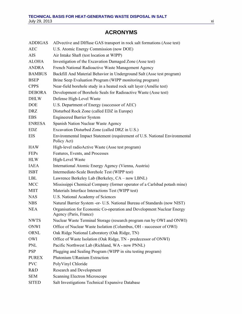
ACRONYMS
ADDIGAS ADvective and DIffuse GAS transport in rock salt formations (Asse test)
AEC U.S. Atomic Energy Commission (now DOE)
AIS Air Intake Shaft (test location at WIPP)
ALOHA Investigation of the Excavation Damaged Zone (Asse test)
ANDRA French National Radioactive Waste Management Agency
BAMBUS Backfill And Material Behavior in Underground Salt (Asse test program)
BSEP Brine Seep Evaluation Program (WIPP monitoring program)
CPPS Near-field borehole study in a heated rock salt layer (Amélie test)
DEBORA Development of Borehole Seals for Radioactive Waste (Asse test)
DHLW Defense High-Level Waste
DOE U.S. Department of Energy (successor of AEC)
DRZ Disturbed Rock Zone (called EDZ in Europe)
EBS Engineered Barrier System
ENRESA Spanish Nation Nuclear Waste Agency
EDZ Excavation Disturbed Zone (called DRZ in U.S.)
EIS Environmental Impact Statement (requirement of U.S. National Environmental Policy Act)
HAW High-level radioActive Waste (Asse test program)
FEPs Features, Events, and Processes
HLW High-Level Waste
IAEA International Atomic Energy Agency (Vienna, Austria)
ISBT Intermediate-Scale Borehole Test (WIPP test)
LBL Lawrence Berkeley Lab (Berkeley, CA – now LBNL)
MCC Mississippi Chemical Company (former operator of a Carlsbad potash mine)
MIIT Materials Interface Interactions Test (WIPP test)
NAS U.S. National Academy of Sciences
NBS Natural Barrier System -or- U.S. National Bureau of Standards (now NIST)
NEA Organisation for Economic Co-operation and Development Nuclear Energy Agency (Paris, France)
NWTS Nuclear Waste Terminal Storage (research program run by OWI and ONWI)
ONWI Office of Nuclear Waste Isolation (Columbus, OH - successor of OWI)
ORNL Oak Ridge National Laboratory (Oak Ridge, TN)
OWI Office of Waste Isolation (Oak Ridge, TN - predecessor of ONWI)
PNL Pacific Northwest Lab (Richland, WA - now PNNL)
PSP Plugging and Sealing Program (WIPP in situ testing program)
PUREX Plutonium URanium Extraction
PVC PolyVinyl Chloride
R&D Research and Development
SEM Scanning Electron Microscope
SITED Salt Investigations Technical Expansive Database
TECHNICAL BASIS FOR HEAT-GENERATING WASTE DISPOSAL IN SALT xii July 29, 2013
SNF Spent Nuclear Fuel
SPDV Site Preliminary Design Validation (early WIPP excavations)
SNL Sandia National Laboratories (Albuquerque, NM)
SSSPT Small-Scale Plugging and Sealing Tests (WIPP test)
THERESA coupled THErmal-hydrologic-mechanical-chemical processes for REpository Safety Assessment (German project)
TRU Trans-Uranic waste
TSDE Thermal Simulation of Drift Emplacement (Asse test)
TSI Thermal/Structural Interactions (WIPP in situ testing program)
UFD Used Fuel Disposition (DOE research program)
WIPP Waste Isolation Pilot Plant (Carlsbad, NM)
WISAP Waste Isolation Safety Assessment Program (NWTS research program)
WPP Waste Package Performance (WIPP in situ testing program)
XRD X-Ray Diffraction
TECHNICAL BASIS FOR HEAT-GENERATING WASTE DISPOSAL IN SALT July 29, 2013 1
ESTABLISHING THE TECHNICAL BASIS FOR DISPOSAL OF HEAT-GENERATING WASTE IN SALT
1. INTRODUCTION This work was supported by the U.S. Department of Energy (DOE) Office of Nuclear Energy within the Office of Used Nuclear Fuel Disposition (UFD) Research and Development (R&D). This report is submitted for Milestone M2FT-13SN0818034 in Work Package FT-13SN081803. This report completes the level-2 milestone for the UFD Campaign Salt R&D Activity 1: “Existing Salt Data Compilation Assessment”. Previously in this activity, historic tests were summarized and an online salt research report database was developed (Kuhlman et al., 2012).
1.1 Intent of Milestone This milestone presents a summary of historic field and laboratory testing done for the purposes of better understanding and predicting the fate of radionuclides in a man-made geologic waste repository in salt. A large number of tests of variable size, quality, and scope have been conducted since salt-related testing for radioactive waste disposal began over 50 years ago. These tests, and the technical knowledge derived from them, culminate in our current understanding (i.e., technical basis) regarding disposal of heat-generating waste in salt. The tests reported here have been conducted under several different programs (e.g., Atomic Energy Commission (AEC), Office of Waste Isolation (OWI), Office of Nuclear Waste Isolation (ONWI), or the DOE), in different countries (i.e., the United States, France, and Germany), for different purposes (e.g., transuranic, defense high-level waste (DHLW), or high-level waste (HLW)), and with differing levels of reporting (e.g., conference papers, journal papers, short reports, or long data reports with appendices).
The intent of this report is to summarize these historic tests and show how they fit into the technical basis, specifically for disposal of heat-generating waste in salt.
1.2 Scope of Milestone We consider a large number of relevant tests that have been conducted in salt. Some more comprehensive or more recent tests subsume or revise information learned from smaller or older tests. The technical basis described here attempts to include the most recent or definitive test on a subject but, when possible, this summary also includes historical tests or programs for completeness. In particular, it is most beneficial to provide the most comprehensive listing of tests feasible, since specifics of a possible future salt repository site are unknown (e.g., whether it is sited in domal or bedded salt). Although completeness is the goal, there are likely to be relevant smaller laboratory testing programs or tests currently in progress, which we have missed.
1.3 Existing Testing Summaries The listing of tests relevant to the technical baseline for disposal of heat-generating waste in salt is a consolidation of numerous sources. Hansen and Leigh (2011) provided a high-level summary of relevant testing and the technical state-of-the art related to disposal of heat-generating waste in salt. As part of this UFD project, Kuhlman et al. (2012) created an online database of salt-based research and testing (the Salt Investigations Technical Expansive Database (SITED) https://sited.sandia.gov/sited). They provided more detailed discussion for many of the historic tests summarized briefly in this report. Callahan et al. (2012) briefly discussed some historic testing performed outside the Delaware Basin (limited to discussion of Project Salt Vault, Avery Island, and a few tests at the Asse facility in Germany). Kuhlman and Malama (2013) recently conducted a more specialized summary of historic testing specific to the movement of brine in heated geologic salt.
TECHNICAL BASIS FOR HEAT-GENERATING WASTE DISPOSAL IN SALT 2 July 29, 2013
From the perspective of the various German salt research programs, Kühn (1985) provided a short historical summary of early German salt in situ tests. Rothfuchs et al. (2004) and Rothfuchs and Wieczorek (2010) provided more recent short summaries of German salt in situ testing. European publications on radioactive waste disposal (including salt, clay, and granite) were listed in the bibliographies compiled by McMenamin (1990b; 1993).
The testing summary in Section 4 of this report contains significant tests mentioned in these previous summaries, and includes numerous test and test programs not discussed in previous UFD reports (e.g., many WIPP Plugging and Sealing Program in situ tests [Section 4.7.3], WIPP borehole plugging experiments, a series of six thermal tests at Asse from 1968 to 1985 [Section 4.9.1], recent Asse drift sealing tests [Section 4.9], recent Morsleben sealing tests [Section 4.10], and both thermal and hydraulic tests at the Amélie potash mine in France [Section 4.8]). The proceedings from the second and third U.S./German workshops on Salt Repository Research, Design and Operation (Hansen et al., 2012a; Hansen et al., 2013), and the SaltMech7 conference (Bérest et al., 2012) have been sources for discussion of recent laboratory tests.
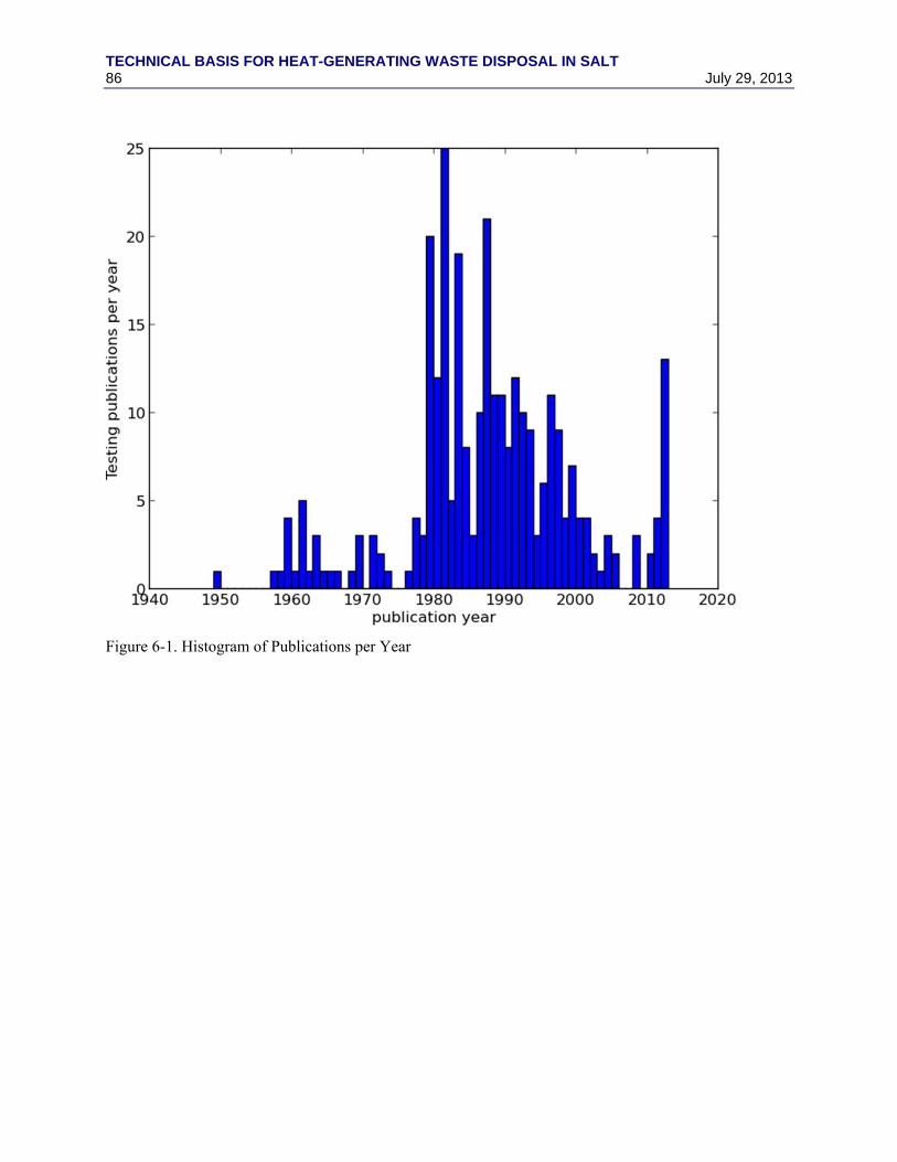
The references in this report have been checked and are available from SITED in searchable electronic format (Adobe pdf). This report intends to build up a concise yet comprehensive listing of relevant reports and papers (see Section 5) to illustrate the existing depth and strength of the technical basis for disposal of heat-generating waste in salt. At the end of the references, (Figure 6-1) a histogram of citations is given for the years since the 1950s. Clearly there is a significant peak in the number of publications in the late 1970s and early 1980s associated with the development towards a high-level radioactive waste repository in salt, before Yucca Mountain was selected in 1987.
1.4 Methodology and FEPs Matrix The technical basis is defined for the purposes of this milestone as the cumulative scientific and practical knowledge about the system of interest, based upon results of relevant experiments, tests, monitoring, and the application of knowledge from related fields. During the development of a site-specific safety case, site characterization plays an important role, but it is not included here because the current emphasis of UFD R&D is generic, not site-specific. The development of the technical basis is an iterative process, typically including the following steps:
1. Develop one or more disposal concepts, including the proposed natural and engineered features and barriers;
2. Understand the relevant multi-physics processes (e.g., heat transfer, geochemistry, or metallurgy) associated with the disposal concepts;
3. Develop conceptual/mathematical models to explain relevant multi-physics processes; 4. Implement numerical models that embody conceptual/mathematical models; 5. Parameterize numerical models using field/laboratory/literature data; and 6. Quantify uncertainty in disposal concepts and designs, data, model choice, and model parameters.
The historic testing reported here provides a large body of input to the technical basis, including data over a wide range of multi-physics processes and couplings of interest in salt repositories. A safety case and associated safety assessment for a geologic repository will typically organize the technical basis using a “features, events, and processes” (FEPs) identification, classification, and screening process (Sevougian et al., 2012). This provides a transparent and robust method to ensure completeness of the technical basis (DOE 1996; DOE, 2008; DOE, 2012) supporting the safety case. However, previous FEPs classification structures (e.g., Freeze et al., 2011; NEA, 2006; NEA, 2000) have been presented in a one-dimensional FEPs listing that works well for completeness but often leads to redundancies in the classification entries that can make it difficult to transparently group related FEPs. This can cause difficulties in finding all related FEPs within the FEP list. To overcome this shortcoming, a new two-dimensional or matrix-based FEP classification approach has been developed to better organize the salt repository FEPs (Freeze et al., 2013). The FEP matrix approach is refined from an earlier application (SNL, 2008 [§6.1.3]).
TECHNICAL BASIS FOR HEAT-GENERATING WASTE DISPOSAL IN SALT July 29, 2013 3
The organization of historical tests in this report is based on the two-dimensional FEPs matrix format. This FEPs matrix, presented in Table 1-1, uses the system features as rows, and the process/events that can act on these features as columns (with “characteristics,” or properties, as an additional column).
TECHNICAL BASIS FOR HEAT-GENERATING WASTE DISPOSAL IN SALT 4 July 29, 2013
Table 1-1. FEPs Matrix (from Freeze et al., 2013) Characteristics,
Processes, and Events
Features
Ch
arac
teri
stic
s
Processes Events
Mec
han
ical
an
d
Th
erm
al-M
ech
anic
al
Hyd
rolo
gic
al a
nd
T
her
mal
-Hyd
rolo
gic
Ch
emic
al a
nd
T
her
mal
-Ch
emic
al
Bio
log
ical
an
d
Th
erm
al-B
iolo
gic
al
Tra
nsp
ort
an
d
Th
erm
al-T
ran
spo
rt
Th
erm
al
Rad
iolo
gic
al
Lo
ng
-Ter
m G
eolo
gic
Clim
ati
c
Hu
man
Act
ivit
ies
(L
on
g T
imes
cale
)
Oth
er
Nu
clea
r C
riti
calit
y
Ea
rly
Fai
lure
Sei
smic
Ign
eou
s
Hu
man
Act
ivit
ies
(S
ho
rt T
imes
cale
)
Oth
er
Waste and Engineered Features Waste Form and Cladding Commercial SNF &
Geosphere Features Host Rock (Repository Horizon) Bedded or Domal Salt Excavation Disturbed Zone Interbeds & Seams
Other Geologic Units Aquifer(s) Unsaturated Zone Pressurized Brine Pocket(s)
Surface Features Biosphere Natural Surface and Near-
Surface Environment
Flora and Fauna Humans Food & Drinking Water Dwellings & Man-made
Surface Features/Materials
System Features Repository System Assessment Basis Preclosure/Operational Other Global
TECHNICAL BASIS FOR HEAT-GENERATING WASTE DISPOSAL IN SALT July 29, 2013 5
1.5 Explanation of FEPs Matrix
1.5.1 System Features (Matrix Rows)
As described in Freeze et al., (2013), the Features axis is organized to generally correspond to the direction of flow and transport, from the waste to the receptor. Features are organized in hierarchical categories. At the top level are feature categories: Waste and Engineered Features (i.e., the Engineered Barrier System (EBS)), Geosphere Features (i.e., the Natural Barrier System (NBS)), Surface Features (i.e., the Biosphere), and System Features. Surface Features include FEPs that are relevant to the calculation of dose to the receptor, which may include radionuclide movement above the subsurface. These portions of the system are site- and regulation-specific and therefore not currently addressed in the technical basis associated with a generic salt repository. System Features include FEPs that are potentially relevant to the repository system as a whole. As shown in Table 1-1, feature categories are subdivided first into feature groups and then into specific features. For example, under the Engineered Barrier System feature category are the feature groups Waste Form and Cladding, Waste Package, Buffer/Backfill, Emplacement Drifts, and Seals/Plugs. Below each of these groups, a further level of detail is often necessary, and may be program-specific. For example, under the Waste Form feature group, there may be a need for a distinction between spent nuclear fuel (SNF) and HLW and commercial and defense waste.
1.5.2 Characteristics, Processes, and Events (Matrix Column)
Although a “characteristic” is not an actual process or event (i.e., not a FEP in the usual sense), the description of the characteristics of each repository system feature is a requirement to model the evolution of processes and events, as they affect the engineered and natural features. Therefore, characteristics are included in the FEP matrix and mapped into the first column of Table 1-1. There are generally one or two characteristic FEPs for each engineered or natural feature (e.g., FEP 2.1.01.01 in Table 2-2 of Freeze et al., 2013).
Processes and events act upon repository features, and each repository feature may in general be affected by each process or event, although some of these combinations are either unlikely or insignificant, such as the thermal effect of the repository on an aquifer hundreds of meters away. Nevertheless, the matrix allows for completeness in this regard, since in a licensing safety case all FEPS must be accounted for, whether included or excluded in the safety assessment model. Processes are phenomena that occur during all or a significant part of the repository period of performance. They may begin at the time of initial waste emplacement (e.g., thermal effects), or may only happen in response to another process or event (e.g., far-field radionuclide transport which occurs after corrosion and breaching of the waste package). Events are phenomena that occur during an interval that is short compared to the repository period of performance. They are typically associated with some sort of change or failure to which a probability can be assigned.
In the column organization, it can be seen that thermal processes have a special emphasis because they are usually a driving or catalyzing force for other processes. Therefore, thermal processes (conduction, radiation, convection) are represented in the matrix as being coupled to other processes. For example, thermal-chemical processes are those in which the thermal state affects the behavior of the chemical environment. Generally, the reverse coupling (in this example, the effect of chemistry change on the thermal state) is significantly weaker than the forward coupling. A more detailed description of the processes and events, as well as complete FEPs listing, may be found in Freeze et al., (2013). Suggested screening of various FEPs in a bedded salt repository system assessment (usually called “performance assessment” in the U.S.) is presented in Sevougian et al., (2012).
TECHNICAL BASIS FOR HEAT-GENERATING WASTE DISPOSAL IN SALT 6 July 29, 2013
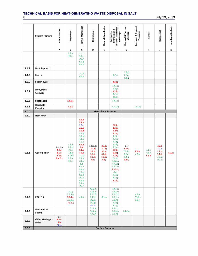
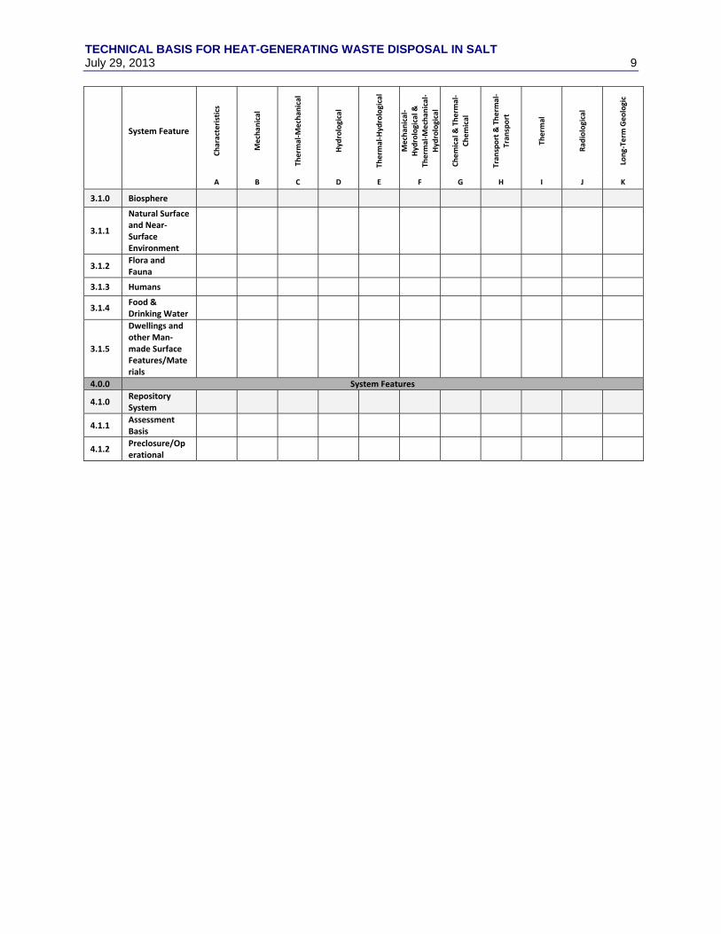
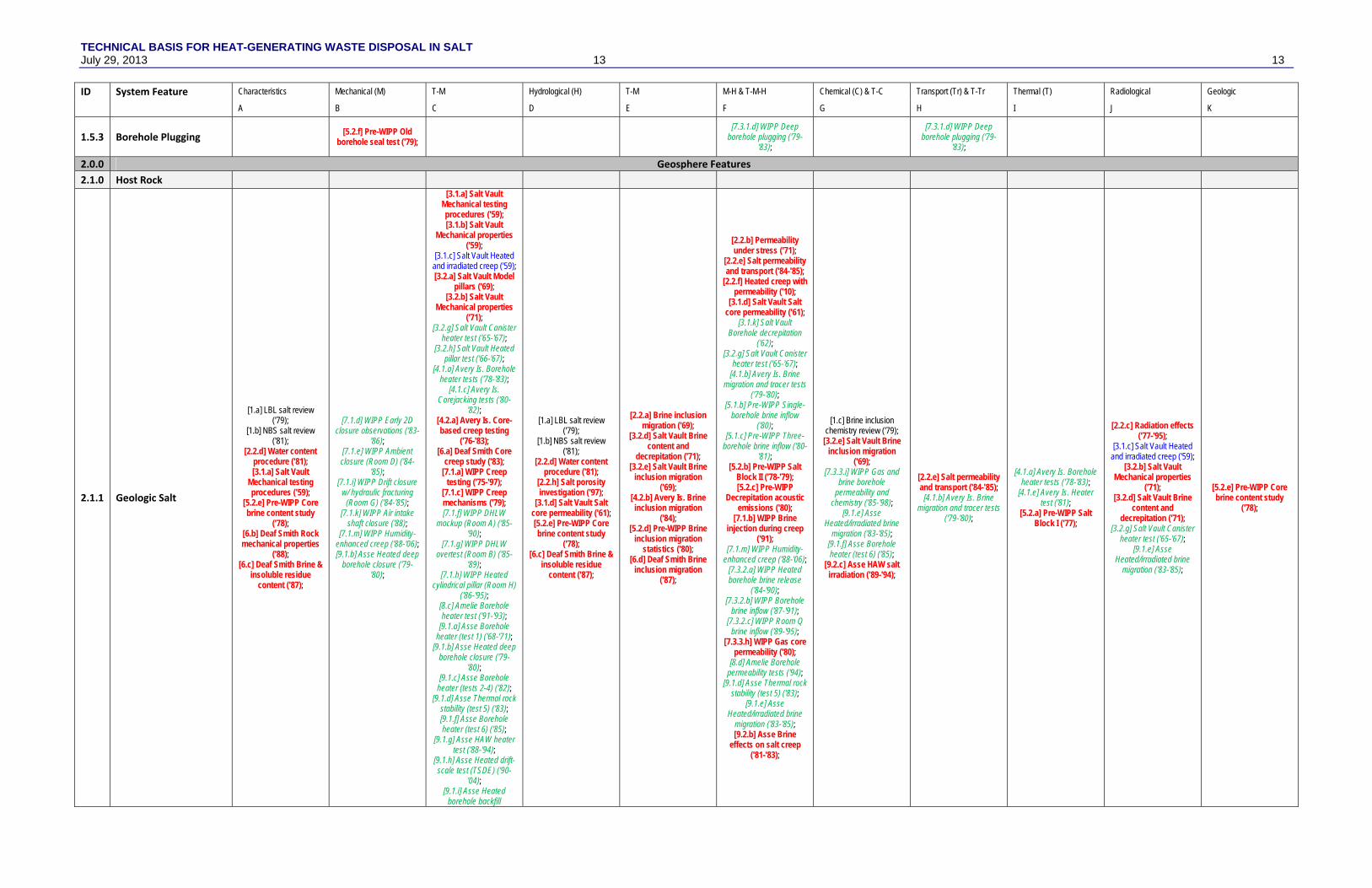
2. MAPPING OF HISTORICAL TESTS TO THE FEPS CLASSIFICATION MATRIX This section maps all the historical salt tests included in this report to the FEPs matrix introduced in the previous section, but with a few minor modifications to the matrix, as described below. Table 2-1 is a concise mapping of each test to a FEPs matrix cell according to a unique “test designator” or “test code”, while Table 2-2 is more detailed mapping that gives more information about each test, including the test code, the test program, a short test name, and the years the test was conducted. Sections 3 and 4 explain the content of these two tables in detail. Section 3 presents the tests organized by features and processes, while Section 4 presents the tests organized by program and/or testing location. Section 4 defines the tests in the greatest detail, while the purpose of Section 3 is to indicate how these tests provide knowledge about the FEPs they were designed to investigate.
The rows and columns of the Tables 2-1 and 2-2 are based upon those in Table 1-1(from Freeze et al., 2013), but have been modified:
Some grouped processes have been divided into separate columns to allow finer-grained distinction of testing processes (e.g., mechanical (A) and thermal-mechanical (B) of Table 2-1 and Table 2-2 are a single column in Table 1-1).
Processes column F of Table 2-1 and Table 2-2 (M-H and T-M-H) is not given in Table 1-1. This column has been added to better represent the brine-migration heater tests.
Some details regarding waste forms and waste packages in Table 1-1 have been consolidated, to simplify Table 2-1, Table 2-2, and the corresponding discussions in Sections 3 and 4.
The biological and thermal-biological column of Table 1-1 is not included in Table 2-1 and Table 2-2, since it had no entries.
Events are not included in Table 2-1 and Table 2-2.
TECHNICAL BASIS FOR HEAT-GENERATING WASTE DISPOSAL IN SALT July 29, 2013 7
Table 2-1. Test Codes in FEPs Matrix (laboratory = bold red, in situ = italic green, both lab/in situ = regular blue, literature survey = black)
TECHNICAL BASIS FOR HEAT-GENERATING WASTE DISPOSAL IN SALT July 29, 2013 9
System Feature
Characteristics
Mechan
ical
Therm
al‐M
echan
ical
Hydrological
Therm
al‐Hydrological
Mechan
ical‐
Hydrological &
Th
erm
al‐M
echan
ical‐
Hydrological
Chemical & Thermal‐
Chemical
Tran
sport & Therm
al‐
Tran
sport
Therm
al
Rad
iological
Long‐Term
Geologic
A B C D E F G H I J K
3.1.0 Biosphere
3.1.1
Natural Surface and Near‐Surface Environment
3.1.2 Flora and Fauna
3.1.3 Humans
3.1.4 Food & Drinking Water
3.1.5
Dwellings and other Man‐made Surface Features/Materials
4.0.0 System Features
4.1.0 Repository System
4.1.1 Assessment Basis
4.1.2 Preclosure/Operational
TECHNICAL BASIS FOR HEAT-GENERATING WASTE DISPOSAL IN SALT 10 July 29, 2013 July 29, 2013
Table 2-2. Test Codes, Test Names, and Years in FEPs Matrix (laboratory = bold red, in situ = italic green, both lab/in situ = regular blue, literature survey = black) ID System Feature Characteristics Mechanical (M) T-M Hydrological (H) T-M M-H & T-M-H Chemical (C) & T-C Transport (Tr) & T-Tr Thermal (T) Radiological Geologic
A B C D E F G H I J K
1.0.0 Waste and Engineered Features
1.1.0 Waste Form & Cladding
[2.3.a] HLW and SNF brine leaching ('77-'79);
[7.2.f] WIPP HLW corrosion studies ('80-
'83);
[2.3.a] HLW and SNF brine leaching ('77-'79); [2.3.b] Actinide sorption
('80); [7.2.f] WIPP HLW
corrosion studies ('80-'83);
1.1.1 SNF & Cladding [7.2.e] WIPP HLW
exposure/interaction (MIIT) ('86-'91);
1.1.2 (D)HLW/Glass [7.2.d] WIPP Heated
DHLW packages ('85-'88);
[7.2.a] WIPP HLW package materials
autoclave ('81); [7.2.d] WIPP Heated
DHLW packages ('85-'88);
[7.2.e] WIPP HLW exposure/interaction
(MIIT) ('86-'91);
1.1.3 Liquid Reprocessing Waste
[3.1.e] Salt Vault PUREX pit mockup ('59);
[3.1.f] Salt Vault PUREX pit tests ('60);
[3.1.e] Salt Vault PUREX pit mockup ('59);
[3.1.f] Salt Vault PUREX pit tests ('60);
[3.1.g] Salt Vault PUREX corrosion ('59-'61);
[3.1.h] Salt Vault PUREX gas production ('59-'61);
1.2.0 Waste Package
[2.3.a] HLW and SNF brine leaching ('77-'79); [3.2.f] Salt Vault Heated hole-liner test ('64-'65);
[3.2.g] Salt Vault Canister heater test ('65-'67);
('78); [6.b] Deaf Smith Rock mechanical properties
('88); [10.b] Gorleben Geotechnical
investigation ('95-'6);
3.0.0 Surface Features
3.1.0 Biosphere
3.1.1 Natural Surface and Near‐Surface Environment
3.1.2 Flora and Fauna 3.1.3 Humans 3.1.4 Food & Drinking Water
3.1.5 Dwellings and other Man‐made Surface Features/Materials
4.0.0 System Features
4.1.0 Repository System 4.1.1 Assessment Basis 4.1.2 Preclosure/Operational
TECHNICAL BASIS FOR HEAT-GENERATING WASTE DISPOSAL IN SALT July 29, 2013 15
3. DESCRIPTION OF TECHNICAL BASIS ACCORDING TO FEPS CLASSIFICATION MATRIX This section organizes and describes the current salt technical basis according to the features and processes of the FEPs matrix (Tables 2-1 and 2-2), by discussing historical tests relevant to those features and processes. Historical tests are briefly described here and mapped to their more detailed description in Section 4, according to their unique test code (indicated by square brackets). This section contains at least one reference (but greater than one when a test addresses multiple features and processes) for each test or study in the sequential test listing of Section 4. For example, laboratory tests are often focused on a single concept or process, and typically fall into a single cell of the FEPs matrix, whereas in situ tests are often more complex, and data collected from these tests can include information which affects several processes or features of the repository system. When mapping a test to the FEPs matrix, it is placed into the “coupled” processes column that most applies to it. For example, heated borehole brine migration tests could potentially be placed into the mechanical, thermal-mechanical, hydrological, thermal-hydrological, or thermal-mechanical-hydrological process columns. Unless a specific sub-test or attribute of the test considered one of the lower-level sets of processes, this heated brine migration test would be placed into the thermal-mechanical-hydrological column of Table 2-1 and 2-2, since intergranular brine migration depends on both heat and stress, and it is a hydrologic process. Some tests include two complementary parts, and are located under two processes; for example, the Asse heated deep borehole [9.1.b] had isothermal portions and heated portions, which were both monitored for creep closure. This test is placed both in the Mechanical and Thermal-Mechanical process columns.
Events from the FEPs matrix are not addressed in this report, because these are often site-specific. One of the goals of repository siting is to avoid repository sites associated with high probabilities for certain unfavorable processes (e.g., volcanic intrusion, seismic hazards, or tsunamis). A second reason for not including events in this analysis is simply because they are typically not the focus of laboratory and in situ research. Instead, research programs focus on understanding the characteristics and physical processes occurring under given conditions.
The remainder of this section presents the historical technical basis sequentially, according to the features (rows) in Table 2-1 and 2-2. For each feature the technical basis is organized according to the testing that has been conducted to evaluate characteristics of the feature and the processes that act on the feature (columns in Table 2-1 2-2). First-level numbering (e.g., 1.0.0 or 2.0.0) corresponds to major feature categories, such as the engineered systems or the geosphere (dark gray rows in Table 1-1, Table 2-1, and Table 2-2). Second-level numbering corresponds to feature groups within a category, such as the waste form or host rock feature groups (e.g., 1.1.0 or 1.2.0 – light gray in Table 1-1, Table 2-1, and 2-2). Third-level numbering refers to specific features, such as tunnel/room backfill or interbeds/seams (e.g., 1.1.1 or 1.1.2 – uncolored rows in Tables 1-1, Table 2-1, and Table 2-2). The ID numbers of features and ID letters for processes (given in the tables in Section 2) are listed in parentheses in the subsection names of this section.
3.1 Waste and Engineered Features (1.0.0) This high-level feature group includes man-made components (e.g., waste and waste packages) and excavation-related repository features (e.g., disposal rooms, boreholes, plugs, and seals). Man-made components are typically well characterized, but often require testing to understand their long-term behavior in a repository setting and their interaction with natural components (e.g., corrosion in a heated brine environment). Excavation-related features are a combination of an engineered opening or closure, in a natural – and therefore heterogeneous – host rock. This interface between man-made and natural features (e.g., room closure or drift seal performance) has been studied in numerous environments, but final design of rooms, plugs, and seals requires site-specific information.
TECHNICAL BASIS FOR HEAT-GENERATING WASTE DISPOSAL IN SALT 16 July 29, 2013
3.1.1 Waste Form & Cladding (1.1.0)
There have been several abandoned U.S. research programs, and ongoing German programs, which investigated the behavior of waste forms and cladding in a salt repository environment. Before the shift to disposal of solidified waste, early tests (pre-1963) investigated the interaction between liquid reprocessing wastes and salt, since this was the disposal concept of the time. After switching to testing solid waste forms (SNF and glass), the NWTS program funded by the Office of Waste Isolation (OWI) and later the Office of Nuclear Waste Isolation (ONWI) from the late 1970s to the early 1980s was abandoned/restructured for funding or programmatic reasons. At WIPP, the in situ MIIT test of the early 1990s successfully investigated the corrosion, degradation, and interaction of high-level waste forms and packaging. The DHLW testing program at WIPP also investigated the in situ behavior of glass waste forms in heated boreholes over 4–5 years. As DHLW/HLW was not part of the WIPP mission after 1979 (U.S. Congress, 1979), these tests were being run at WIPP in anticipation of a HLW bedded salt repository being sited elsewhere (i.e., the Deaf Smith site in Texas). Investigation of other DHLW/HLW salt repository alternatives was stopped when Yucca Mountain was designated the only repository option for U.S. waste by an amendment to the Nuclear Waste Policy Act (U.S. Congress, 1987).
Due to these historical circumstances, there has not been a significant and recent U.S. effort to understand the interaction of waste forms and waste cladding in a salt environment, since DHLW and HLW material testing at WIPP, which ran until the early 1990s. German HLW testing programs have continued to tests corrosion and effects of radiation on waste forms and package, with the most recent in situ testing associated with the BAMBUS II project (Bechthold et al., 2004).
3.1.1.1 Characteristics (A)
The waste form itself is one of the most well-known components in the repository system. Waste form and cladding components in the U.S. can be subdivided into spent nuclear fuel (SNF), high-level waste (HLW), and defense high-level waste (DHLW). In Germany, wastes are separated into heat-generating and non-heat-generating wastes. When salt was still being considered a host medium for HLW in the U.S. (before 1987), several relevant waste form and waste packaging specifications were published, including design of: DHLW (Baxter, 1981), Commercial HWL (Slate et al., 1981; Beradzikowski et al., 1987; Kehrman et al., 1987), and SNF (Odgers and Collings; 1981; Westinghouse, 1983). Brodersen and Nilsson (1989) and Smith and Green (1989) characterized several European waste forms and package types, for disposal in clays, crystalline rocks, and salt. These specifications are not the result of testing, and are therefore not listed in the FEPs matrix framework.
3.1.1.2 Mechanical (B), Thermal-Mechanical (C), Chemical, and Thermal-Chemical (G) Processes
Because of the limited number of tests considering the interactions of waste forms and salt, the processes are grouped together in this section. Waste form research carried out for disposal of heat-generating waste in non-salt waste programs (e.g., tuff, clay, or granite) may be applicable to the technical basis for heat-generating waste disposal in salt.
1) ORNL conducted laboratory and in situ tests with liquid wastes in the 1950s and early 1960s, to investigate the potential to dispose liquid reprocessing wastes directly into salt cavities [3.1.e, 3.1.f, 3.1.g, 3.1.h]. A series of laboratory tests investigated the corrosion and gas-generation potential of reprocessing waste (including PUREX) in bedded salt. These tests revealed issues with salt cavity stability and containment of generated gas. Based on these findings, subsequent tests have focused on the disposal of solidified wastes in salt.
2) The Waste Isolation Safety Assessment Program (WISAP) workshop [2.3.a, 2.3.b] in 1979 included discussion of results from then-ongoing PNL laboratory sorption/desorption, leaching, corrosion, and degradation experiments with different HLW components. These tests included spent fuel and waste containment materials. A 95-day joint PNL/SNL autoclave test [7.2.a]
TECHNICAL BASIS FOR HEAT-GENERATING WASTE DISPOSAL IN SALT July 29, 2013 17
included waste-form glass (with uranium), along with package materials, in an autoclave at 250° C for 95 days.
3) The Nuclear Waste Terminal Storage (NWTS) program published a significant and detailed “test plan” in 1981 [7.2.f]. This plan documented what were believed at the time to be the testing requirements to understand interactions between waste forms, waste structural components, and emplacement backfills. The tests in this plan were not all conducted before termination of NWTS.
4) The in situ WIPP DHLW packages experiments [7.2.d] placed four full-sized non-radioactive DHLW glass-filled containers in vertical boreholes in Room B at WIPP for up to 3 years. The four packages were not heated, but they were surrounded by heaters in nearby boreholes. These packages were removed in 1988 for laboratory testing of the glass and surrounding waste packages.
5) The in situ WIPP WPP MIIT experiment [7.2.e] exposed 980 pineapple-slice-shaped coupons of 15 different waste forms under heated (90° C) brine-saturated conditions for up to 5 years, with additional samples collected at 6 months, 1 year, and 2 years. Waste form samples included a glass ceramic form, an aluminosilicate form, and a TRU waste glass system, which were obtained for MIIT from several international collaborators.
3.1.2 Waste Package (1.2.0)
Waste packages are a man-made feature of the repository environment, and are typically engineered to withstand corrosion or physical damage, to facilitate possible retrieval, and potentially provide a beneficial chemical environment for long-term performance of the repository (e.g., corrosion of iron in waste packages can help ensure a reducing environment).
The importance of waste package mechanical and chemical resistance depends upon how it will be included in the repository safety case. For example, at WIPP all waste packages are assumed to be mechanically failed and fully corroded for performance assessment modeling. If the waste packages will be used to provide some level of separation between the waste form and the host rock, more thorough understanding of waste/package/salt interactions is necessary.
3.1.2.1 Characteristics (A)
The specification of waste packages is typically an engineering rather than scientific endeavor, but design should be consistent with scientific understanding. When salt was still being considered a host medium for HLW in the U.S. (pre 1987), several relevant specifications for waste forms and packages were published, including design of: DHLW (Baxter, 1981), Commercial HWL (Slate et al., 1981; Kehrman et al., 1987), and SNF (Westinghouse, 1983). Brodersen and Nilsson (1989) and Smith and Green (1989) characterized several European waste forms and package types, for disposal in clays, crystalline rocks, and salt. Molecke et al. (1982) summarized the results of a testing program at SNL, which investigated the use the titanium alloy Ti-code12 for waste packages.
3.1.2.2 Mechanical (B) and Thermal-Mechanical (C)
The mechanical and thermal-mechanical behavior of various proposed waste package designs have been extensively studied in general. The following tests include observations regarding their behavior specifically in a salt environment.
1) The in situ WIPP DHLW package experiments [7.2.d] placed 18 full-sized simulated DHLW packages in vertical boreholes in Rooms A1 and B. These packages were removed in 1988 for laboratory testing of waste packages. The primary mechanical load on the packages is due to borehole closure. Some of the heated packages were simply removed in 1988 by pulling them up by their pintle (i.e., handle). Others waste packages had become stuck and were overcored to
TECHNICAL BASIS FOR HEAT-GENERATING WASTE DISPOSAL IN SALT 18 July 29, 2013
remove both the exposed waste packages and associated backfill or salt deposits (Krumhansl et al., 1991b; Schuhen et al., 2013).
2) SNL performed laboratory mechanical testing of titanium alloys under repository conditions. Their testing showed the TiCode-12 alloy to be a superior material for waste packages, and created alternative waste package and overpack designs to the mild steel packages specified for DHLW by ONWI design [7.2.g], which were used in the WIPP in situ WPP tests in Rooms A1 and B. Titanium alloy package involved much less material and were lighter weight than equivalent overpacked ONWI waste package designs, but TICode-12 package strength was not an issue.
3.1.2.3 Chemical and Thermal-Chemical (G)
The corrosion of waste package materials in salt is a significant concern, due to the potentially corrosive nature of the salt repository environment. Many laboratory and in situ tests have been conducted to investigate the behavior of proposed waste package materials (mostly steel and titanium alloys) in brine. WIPP WPP DHLW canister experiments and the TSDE experiment at Asse showed the excellent behavior of titanium alloys in both bedded and domal salt environments. Other experiments have included tests of related materials, which are analogous to waste packages or might be in a repository environment associated with waste packages (e.g., instrumentation, heaters, PVC, Teflon, and graphite).
1) The in situ WIPP DHLW package experiments [7.2.d] placed 18 full-sized simulated DHLW packages in vertical boreholes in Rooms A1 and B. Test packages included TiCode-12, 304L stainless steel, and mild steel packages and overpacks. Twelve packages had intentional defects and some had 100 liters additional brine added to the borehole annulus to accelerate corrosion and degradation. These packages were removed in 1988 for laboratory testing of waste packages. The TiCode-12 packages had almost no visible corrosion from exposure for over 3 years.
2) The in situ WIPP WPP MIIT experiment [7.2.e] exposed 278 pineapple-slice-shaped coupons of canister or overpack materials under heated (90° C) brine-saturated conditions for up to 5 years. Metal samples were obtained for MIIT from several international collaborators.
3) The Waste Isolation Safety Assessment Program (WISAP) workshop [2.3.a] in 1979 included discussion of results from then-ongoing PNL laboratory sorption/desorption, leaching, corrosion, and degradation experiments with different HLW components. Tests included corrosion, leaching, and degradation high-level glass wastes and waste containment materials in salt brines. A 95-day joint PNL/SNL autoclave test [7.2.a] included package materials with salt and backfill in an autoclave at 250° C for 95 days.
4) SNL performed laboratory corrosion testing of titanium alloys under repository conditions. Their testing showed the TiCode-12 alloy to superior for waste packages from a corrosion point of view [7.2.g]. The WIPP in situ WPP tests in Rooms A1 and B included SNL-designed waste packages with reference ONWI-designed canisters.
5) ORNL laboratory and in situ tests investigated the corrosion of different waste package materials (e.g., stainless steel, steel alloys, titanium, Teflon, PVC, and graphite) in simulated PUREX reprocessing waste in bedded salt [3.1.e, 3.1.f, 3.1.g]. These tests revealed issues with salt cavity stability and containment of generated gas. Corrosion in pH-neutral salt-saturated wastes was minimal, while corrosion in acidic salt-saturated waste was extensive, completely dissolving some of the metal samples.
6) SNL material interaction tests in the MCC potash mine included exposure over weeks to months of metal coupons of candidate waste package materials under heated, brine-saturated conditions in boreholes with added brine. These results showed corrosion of titanium, nickel, and iron-based alloys was not detectable, but significant pitting of Cr-Mo steel and copper was detected [5.1.d].
TECHNICAL BASIS FOR HEAT-GENERATING WASTE DISPOSAL IN SALT July 29, 2013 19
7) A comprehensive corrosion study was performed in both the laboratory and in situ at Asse [2.4.c]. Several carbon steels, and titanium alloys were exposed to a range of salt brine compositions, at a range of temperatures, with and without gamma radiation over the course of two years (Smailos et al., 1996).
8) Corrosion studies were made on container, shielding, and canister metal samples from the Asse TSDE (Bechthold et al., 2004 [§5]). Samples were heated in situ for 9 years in a crushed-salt-backfilled drift [9.1.h]. Results showed titanium alloys performed the best, but several Hastelloy alloys also performed well (Hastelloy refers to a trademarked group of corrosion-resistant, primarily nickel-based steel alloys made by Haynes International).
9) Observations have been made of in situ corrosion of instrumentation (e.g., extensometers, thermocouples, and pressure gages), borehole liners, and heaters [3.2.c, 3.2.f, 3.2.i, 7.1.n, 9.1.e]. Although these are not waste-package specific, these observations of the corrosion resistance of different materials represent a great deal of real-world knowledge regarding long-term performance of materials in a salt environment.
10) The in situ WIPP TRU waste package tests included tests on contact-handled (steel drums) and remote-handled (horizontal canisters) TRU waste packages under reference and “overtest” (wet and hot environment) conditions at WIPP (Rooms J and T) [7.2b-c]. Room J included investigations on the corrosion of painted steel drums either partially submerged in heated brine pools or partially covered with damp crushed salt backfill.
3.1.3 Buffer/Backfill (1.3.0)
The buffer or backfill material surrounding waste packages and filling excavations potentially serves several purposes in the salt repository environment. Backfill reduces void spaces created by excavation to emplace the waste, reducing the duration of time required for the salt to close in around the waste. Since the DRZ in salt due to the excavation will not heal until it closes in on something, backfill also reduces the duration of time until healing of the salt occurs. Buffers can also be designed with favorable chemical and transport properties, which create an environment to either reduce corrosion or adsorb radionuclides potentially released from failed waste packages.
Several different types of backfills have been considered for use in a salt repository environment:
1) Run-of-mine (i.e., crushed) salt,
2) Salt/bentonite mixtures, and
3) Bentonite/sand mixtures.
Mixtures of salt, sand, and bentonite were considered in earlier testing (1970s and 1980s), but more recently research has focused on using nearly unmodified run-of-mine salt (e.g., see DEBORA Phase I – Rothfuchs et al., 1996b). Crushed salt is readily available in a repository, will eventually reconsolidate to its undisturbed state, and it adds no new potentially complicating chemical constituents to the repository system.
Bentonite has been considered as a favorable additive because it sorbs radionuclides, it is used as a low-permeability sealing material, and it will likely absorb water during early stages of the repository. One possibly complicating factor is the possible metamorphosis of bentonite to other clays with less favorable properties at high temperatures.
A series of historic laboratory tests were conducted (e.g., see summaries in Spiers et al. (1988) and Krumhansl et al. (2000)) in the pursuit of better understand the physical processes and properties associated with reconsolidation of backfill materials in a repository setting. Testing on various aspects of the backfill reconsolidation problem this continues to the present day (e.g., crushed salt reconsolidation to very low porosities, salt reconsolidation at elevated temperatures, or dissolution and recrystallization
TECHNICAL BASIS FOR HEAT-GENERATING WASTE DISPOSAL IN SALT 20 July 29, 2013
processes due to moisture redistribution in backfill). Regarding crushed salt backfill, there has been some effort to promote a synthesis regarding the constitutive models used in simulating both crushed salt reconsolidation and intact salt healing (e.g., Callahan and Hansen, 2000; Stührenberg and Schultze, 2012).
3.1.3.1 Characteristics (A)
Aside from the effects the different host rocks have on the backfill (e.g., rate and nature of closure or brine type and quantity), information regarding the characteristics of potential backfill materials can also be found in repository research for non-salt repositories. The research performed for clay repositories can be utilized when considering clay backfill materials.
3.1.3.2 Thermal (I)
1) In project Salt Vault, 22 heated boreholes associated with the heated pillar test were backfilled with different materials in the heated pillar test [3.2.h]. Comparison of the thermal profiles associated with the different backfills, showed crushed salt to lead to the lowest temperatures, due to salt’s high thermal conductivity compared to quartz sand or air.
2) Some material interactions tests at the MCC potash mine [5.1.d] and laboratory tests associated with the Amélie potash mine [8.b] included heater tests designed to estimate the thermal conductivity of crushed salt backfills.
3.1.3.3 Mechanical (A) and Thermal-Mechanical (C)
The mechanical and thermal-mechanical behavior of crushed salt has been characterized in numerous laboratory testing programs. Although there are likely several laboratory testing programs which may not be included here, this list is representative of the types of tests being conducted.
1) Some early crushed salt reconsolidation tests were performed associated with the WIPP program (see summary by Holcomb and Sheilds, 1987) [7.3.1.b]. Hansen (1976) performed laboratory quasi-static creep tests on crushed salt at room temperature, 100° C and 200° C, under stresses between 7 and 28 MPa. Steinbaugh (1979) performed hydrostatic crused-salt compressibility tests up to 21 MPa and 82° C, using samples from a Carlsbad potash mine. Holcomb and Hannum (1982) performed similar crushed salt reconsolidation tests, finding creep consolidation rate under hydrostatic pressure to be proportional to inverse time (i.e., continually decelerating consolidation rate as the experiment progressed). They also found creep consolidation of crushed is not very temperature dependent between 21° C and 100° C, unlike the temperature-dependence of creep in intact salt.
2) Pfeifle (1987) investigated the mechanical behavior of two different DHLW backfill designs for emplacement around canisters in vertical boreholes [7.3.1.b]. Unconfined compression tests were conducted using crushed WIPP salt. Unconfined and hydrostatic compression (at 20° C and 100° C), creep consolidation (at 20° C and 100° C), and swell tests were conducted on a 70/30 (by weight) bentonite/sand mixture. Estimates of relevant mechanical properties were developed for crushed salt and the bentonite/sand mixture. He also found consolidation to slow considerably with time, and found no significant temperature dependence for creep.
3) Laboratory salt reconsolidation tests were done by ANDRA (Ghoreychi et al., 1989) before tests in the Amélie potash mine [8.b]. Tests included determination of thermal conductivity (1/10 that of intact salt), oedometric tests, and triaxial compression tests under various temperatures. Between the triaxial and oedometer tests, the behavior of the crushed salt was classified as elastoplastic.
4) Korthaus (1998) conducted ambient temperature “true triaxial” laboratory compression tests on crushed salt [9.2.i]. True triaxial tests are more difficult to conduct. They apply different stresses
TECHNICAL BASIS FOR HEAT-GENERATING WASTE DISPOSAL IN SALT July 29, 2013 21
in three orthogonal directions, rather than making the two smaller stress equal (i.e., a lateral confining stress on a cylindrical sample), as is done in standard triaxial tests.
5) Heated triaxial crushed salt compression tests [2.1.e] have recently been carried out at SNL (Hansen et al., 2012b), to develop and parameterize crushed salt constitutive models under heated conditions (ambient to 250° C and up to 20 MPa).
6) The WIPP shaft seal development program involved dynamic reconsolidation experiments, which were used to refine and parameterize constitutive models for salt reconsolidation [7.3.1.e].
In situ testing of the mechanical behavior of crushed salt includes:
1) At the domal Avery Island site, heater site C [4.1.a] included crushed salt backfill between the borehole wall and a steel sleeve. Site C was heated with 9.6-kW of heaters for 5 years.
2) DHLW tests in WIPP Rooms B and A1–A3 involved different backfill materials between the heaters and vertical boreholes (Schuhen et al., 2013) [7.1.f, 7.1.g, 7.3.1a]. With powers of 0.5-kW to 4-kW, the heaters operated for 4–5 years, with hottest temperatures attained in Room B (DHLW overtest).
a. Heaters in Rooms A2 and A3 involved no waste packages, and all used run-of-mine crushed salt. These heaters remain in place and have not been sampled or removed for testing.
b. Room A1 included both waste packages and heaters with various backfills, including air (no backfill), crushed salt, and a mixture of 30/70 crushed salt/bentonite. All these canisters and backfills remain in place and have not been sampled or removed for testing.
c. Room B included both waste packages and heaters, with various backfill materials used between the borehole and heaters, including air, crushed salt, table salt, and a mixture of 30/70 crushed salt/bentonite. The waste packages and their associated backfills were overcored at some locations in 1988, conducting laboratory analyses on samples (Krumhansl et al., 1991b).
3) TRU tests in WIPP Rooms T and J [7.2.b-c] placed crushed salt or 70/30 crushed salt/bentonite over stacks of steel drums. The backfill in Room J was exposed to hotter (40° C) and wetter conditions. Samples of backfill were analyzed after exposure for several years. The drums and dry backfill in Room T still exist underground at WIPP; they were never retrieved (Schuhen et al., 2013).
4) In situ borehole crushed-salt reconsolidation tests were conducted by ANDRA in the Amélie potash mine [8.a]. Three different grain-size distributions of salt were used. No significant difference was observed in the behavior of the different crushed salts. Between the laboratory and in situ tests, it was concluded the heat did not make the crushed salt behave significantly than it does at room temperature (unlike intact salt). Laboratory and in situ results were comparable.
5) The DEBORA-1 and DEBORA-2 borehole heater tests at Asse [9.1.i] involved placing crushed salt in heated 15-m deep vertical boreholes, along with gas injection and collection equipment. In situ gas flow measurements were used to estimate the change in porosity and permeability of the crushed salt backfill during heating. Results showed crushed salt porosity reduced from ~38% to ~10% during a year of heating. Permeability of the crushed salt reduced approximately 2 orders of magnitude over the same period.
Engineered backfills have been used in two borehole heater tests at Asse, with the intention of allowing brine and gas sampling during heating and eventual borehole closure.
TECHNICAL BASIS FOR HEAT-GENERATING WASTE DISPOSAL IN SALT 22 July 29, 2013
1) The two heaters in the HAW test at Asse [9.1.g] were identical but only one used backfill. Heater B1 had no backfill, allowing the borehole to unrestrictedly close on the heater. Heater A1 had the annulus between the heater and borehole backfilled with a ceramic aluminum beaded porous medium, to allow access and sampling of the gasses and liquids, which entered the borehole during heating.
2) The heated borehole brine migration test [9.1.e] also used an engineered aluminum bead porous medium in the annular space between the heaters and borehole wall.
3.1.3.4 Hydrological (D), Thermal-Hydrological (E), Mechanical-Hydrological, and Thermal-Mechanical-Hydrological (F)
The mechanical and hydrologic behavior of crushed salt has been investigated in the laboratory for both ambient and heated conditions.
1) Shor et al. (1981) investigated the consolidation of crushed salt under the influence of several controlling variables [7.3.1.b]. Consolidation was performed for crushed salt with added brine, dodecane, and air. Tests using dodecane first revealed only small amounts of brine are needed to accelerate crushed salt reconsolidation (Holcomb and Shields, 1987). They observed significant variability in the reconsolidation within specimens, related to the position relative to the walls or ends of the sample. Higher temperatures (85° C) led to somewhat faster consolidation and less variability across the sample. Sample permeability was found to decrease rapidly as a function of porosity.
2) Spiers et al. (1988) [2.1.b] performed laboratory crushed salt consolidation and sample gas permeability tests on domal salt samples from Asse. The testing aimed to develop predictive models for crushed salt reconsolidation with and without added brine, and to create an “optimal backfill” recipe.
3) Ambient temperature oedometer crushed salt reconsolidation tests have been performed by several researchers (ENRESA, 1995; Wieczorek et al., 2012) to investigate the mechanical properties of crushed salt (e.g., void ratio or bulk modulus) under variable confining stress [2.1.c, 2.1.f].
4) Castagna et al. (2000) and Olivella et al. (2011) [2.1.d] investigated changes in porosity of crushed salt samples due to applied thermal gradients. Porosity changes were caused through dissolution and precipitation of salt, driven by brine and vapor transport in the salt.
5) The WIPP Room J backfill tests included exposing both crushed salt and 70/30 crushed salt/bentonite mix to a heated (40° C) brine pool for 3.75 years, which contained added tracers. The foot of the salt pile was in contact with the brine pool, to monitor the ability of the salt to wick moisture and tracers. Backfill material samples and brine specimens were collected at 0.5, 1, 2, 2.5, 3, and 3.75 years. Crushed salt and mixed salt/bentonite backfill had higher water content in samples collected near the brine pool (6–12 %). Mixed backfill away from the brine pool only had water contents of 0.5–4%, despite the high humidity of Room J. After 3.75 years, brine had wicked 60–100 cm into the crushed salt backfill pile.
3.1.3.5 Chemical and Thermal-Chemical (G)
The chemical properties of crushed salt backfill:
1) The chemical properties of desiccant backfills (MgO, CaO, and mixtures of the two) were investigated by Simpson (1980) [2.1a] in a salt repository environment. Both oxides were found to have potentially beneficial properties for use as a salt repository desiccant. MgO is used at WIPP as an engineered barrier to reduce potential problems with gas generation and to provide pH buffering capacity.
TECHNICAL BASIS FOR HEAT-GENERATING WASTE DISPOSAL IN SALT July 29, 2013 23
In situ tests related to the chemical behavior of backfill have
1) The WIPP Room J backfill tests included crushed salt and 70/30 crushed salt/bentonite mix placed next to a heated (40° C) brine pool with tracers for about 4 years. Areas where the backfill had higher moisture content were associated with increased corrosion in waste packages. Removal of drums from damp backfill was difficult, requiring shovels and jackhammers (Molecke et al., 1993c). Drums sitting in the brine pool had their paint coating flaked off, but were not rusted after 12 months of exposure. By the end of the test (3.75 years), all drums had pronounced corrosion – especially at the air/brine interface.
2) DHLW tests in WIPP Rooms B and A1–A3 involved different backfill materials between the heaters and vertical boreholes (Schuhen et al., 2013) [7.1.f, 7.1.g, 7.3.1a]. With powers of 0.5-kW to 4-kW, the heaters operated for 4–5 years, with hottest temperatures attained in Room B. Krumhansl et al (1991b) analyzed backfill and salt deposits from a Room B heater used in the brine migration test (no backfill and flushed continuously with dry nitrogen). The salts deposited in the annular space and near-field host rock were consistent with salt from brine that flowed to the borehole before the borehole reached boiling temperatures (~400 days).
3.1.3.6 Transport and Thermal-Transport (H)
1) The WIPP Room J backfill tests included exposing both crushed salt and 70/30 crushed salt/bentonite mix to a heated (40° C) brine pool for about 4 years, which contained added tracers. The foot of the salt pile was in contact with the brine pool containing Cs+1 and I-1 tracers, to monitor the ability of the salt to wick moisture and tracers. Tracers included Eu, Sm, and Gd as trichlorides. Tracers were placed under select drums, near the base of the backfill as 5-cm compressed disc (Molecke et al., 1993c). Based on core samples collected at the end of the test (3.75 years), Eu was found to have diffused into the backfills a few cm during the test, while Sm and Gd had traveled further from the sources.
3.1.4 Emplacement Drifts & Mine Workings (1.4.0)
The emplacement drifts and mine workings are the portion of the repository open during the operational phase, which are typically sealed or plugged before final repository closure. Most experience with closure of mined openings in salt is derived from mines developed for the purpose of resource extraction (e.g., Lyons Carey salt mine, Avery Island salt mine, MCC potash mine, or Asse), rather than facilities developed expressly for waste disposal (e.g., WIPP or Gorleben). There are a large number of open mines in salt, which have long histories of operation and maintenance (some over 100 years). Some salt mines have failed catastrophically due to inflowing groundwater problems (e.g., Retsof, New York mine flooding (Van Sambeek, 1999)) or had brine inflow issues (e.g., portions of the Asse facility). Lessons can be learned from the mining industry on these events.
Waste repositories can and should be designed differently than resource extraction mines, to optimize the construction of the facility for both operational safety (i.e., minimize rockfall and requirements for rock bolting) and convenience (i.e., accommodate clearance necessary for required repository vehicles, packages, and personnel). Part of the design includes determining the optimum placement of waste from an operational efficiency point of view. Waste packages should be as close enough together as possible without creating additional complications due to high heat or radiation loads. Cheverton and Turner (1972) and Russell (1979) developed early recommendations for repository design related to waste package density, based on data and calculations regarding the waste composition and near-field temperatures expected in a salt repository for different types of waste (HLW and spent fuel).
3.1.4.1 Mechanical (B)
The basic processes at work in the geomechanics of salt have been well known for several decades (e.g., Serata and Gloyna, 1959; Serata and Milnor, 1979). Deformation of unheated mined openings in salt has
TECHNICAL BASIS FOR HEAT-GENERATING WASTE DISPOSAL IN SALT 24 July 29, 2013
been investigated in the following repository locations related to repository science investigations. There are likely many more observations of closure that could be obtained by looking outside the field of repository science, since this is a common interest of the salt mining and salt-cavity gas storage industries. When making room closure observations, the deformation observed immediately after initial mining are quite important. Room closure observations made in operational or old mines are less useful in analysis, due the ambiguity related to how much deformation has been missed. A great deal of effort was put into making early observations of closure in the WIPP TSI program.
Room closure observations in mines or former mines
1) Large-deformation closure was monitored at the bedded salt MCC potash mine, near present-day WIPP [5.1.a]. The high extraction at this mine (~90% removed) led to rapid closure (~1cm/day).
2) The domal salt in the Grand Saline salt mine, near Dallas, Texas, was monitored for creep closure as part of pre-Salt Vault testing by the University of Texas [3.1.c].
3) Closure observations were made in bedded salt of the Hutchinson and Lyons Carey salt mines were made as part of the Salt Vault investigation by ORNL [3.2.j]. Some observations were continued for over 10 years (McClain, 1973).
4) A salt pillar stress test was conducted at Asse [9.2.a] using flatjacks inserted into slits made in pillars between larger rooms. The test measured the pressures applied to pillars by the encroaching country rock.
Room closure observations in purpose-built repositories
1) WIPP SPDV South Drift [7.1.e] was a long straight drift, which could accurately be considered two-dimensional, allowing comparison of measured closure observations against preliminary numerical models. This dataset led to the first realization of a factor-of-three discrepancy between models parameterize using tests conducted on cores, and real-world observations. WIPP Room G [7.1.i] was also a long straight isolated drift with a significant dataset of closure data (oriented at a right angle to the SPDV South Drift). Estimates of the in situ stress state were also made from two sets of hydraulic fracturing tests conducted in Room G.
2) WIPP Room D was an unheated analog to heated Room B, with similar geometry. The combination of Room D with heated room B makes a good candidate for a model benchmarking dataset (e.g., Munson et al., 1990a; Argüello and Rath, 2013).
Room closure in different scale cylindrical excavations
When discrepancies were observed between WIPP SPDV room closure observations and model predictions, it was hypothesized that the difference may be attributed to scale effects. A series of different scale tests (aside from “full scale” rectangular rooms like Room G and SPDV South Drift) were monitored for room closure to confirm the behavior was not due to scale effects. Cylindrical excavations provide a high degree of symmetry, and have fewer stress concentrations than rectangular excavations.
1) Fuenkajorn and Daemen (1988) conducted laboratory studies [7.3.3.g] of borehole closure in samples of Salado salt (cm-sized openings). These borehole-closure tests are complemented by the extensive amount of salt creep data obtained from salt cores taken from boreholes of approximately similar size [7.1.a].
2) The 300-m deep 0.315-m diameter vertical borehole completed at Asse [9.1.b] had borehole closure data collected for more than 800 days before portions of the borehole were heated (Doeven et al., 1983). Another 500-m deep vertical borehole (0.6-m diameter) was later drilled at Asse [9.2.j], and had similar ambient temperature borehole convergence data collected at several depths over 4 years.
TECHNICAL BASIS FOR HEAT-GENERATING WASTE DISPOSAL IN SALT July 29, 2013 25
3) The WIPP Intermediate-scale borehole test [7.1.j] was a 0.9-m diameter horizontal borehole through a 10-m pillar between Rooms C1 and C2 in the WIPP north experimental area.
4) The WIPP Room Q brine inflow borehole [7.3.2.c] was a 2.9-m diameter horizontal cylindrical room mined with a tunnel-boring machine (i.e., a large borehole) 109-m into a relatively undisturbed portion of the WIPP underground.
5) The WIPP Air-Intake Shaft [7.1.k] was a 6.2-m diameter cylindrical vertical shaft completed to its final diameter with an up-reaming drilling rig, which provided a smooth and rapid completion compared to traditional drill and blast techniques, aside from some difficulties when the up-ream bit got stuck. An apparatus was developed to follow the mining machine up the borehole, installing temporary closure observation points in the Salado salt as soon as possible.
Each of these tests in this series of increasing large scale boreholes in salt can be interpreted using the same constitutive models, showing the models do not have serious scale-dependent flaws.
3.1.4.2 Thermal-Mechanical (C)
The accelerating effect that heat has on the creep closure of excavations in salt has been studied extensively through large-scale in situ experiments and from laboratory tests on heated core samples. Every major heated in situ salt test has involved some monitoring of room closure. Many of the large number of tests and datasets have been used to advance the state of constitutive models, used in geomechanical numerical simulations.
1) ORNL and the University of Texas conducted several heated room closure experiments in the Hutchinson and Lyons Carey salt mines (bedded salt), which monitored how room closure was accelerated by the heat input from testing [3.1.i, 3.1.j, 3.2h]. Project Salt Vault also included a fairly extensive laboratory model pillar study, which observed creep in 0.4-m diameter samples of salt from several different salt mines [3.2.a]. Some of the heated pillar tests ran over 15 years.
2) RE/SPEC conducted measurements of roof-to-floor closure and pillar expansion during the 5 years of heater tests in dome salt at Avery Island (Stickney and Van Sambeek, 1984) [4.1.a]. Accelerated borehole closure (i.e., corejacking) tests at Avery Island monitored heated closure [4.1.c]; these closure data were used to test and validate constitutive models for salt creep under a wide range of conditions (DeVries, 1987).
3) SNL monitored differential room closure, along with many other parameters, in the large WIPP TSI experiments in Rooms A1-A3, B, and H [7.1.f-h]. Rooms A1-A3, B, and D (unheated) were all of similar dimensions (5.5 m square room profile, approximately 70-m long at their full cross-sectional diameter) and in the same geologic horizons. Room D was ambient temperature, Rooms A1-A3 were operated at DHLW design thermal load (18 W/m2), and Room B was an overtest, which had more three times the thermal load of the A rooms. The three levels of heat in similar shaped rooms, each with similar high-quality room closure datasets, provide a unique model validation dataset (e.g., Munson et al., 1990a; Argüello and Rath, 2013).
4) At Asse several heated experiments monitored creep closure within boreholes [9.1.b, 9.1.c, 9.1.d, 9.1.i]. Only the DEBORA-1 and -2 boreholes were filled with crushed salt, the others were not backfilled. Borehole closure in the heated section of the 300-m borehole is nearly ideal (radially symmetric and sufficiently distant from the access drift), and has already been used as a validation dataset for numerical models [9.1.b]. The thermal rock stability test #5 [9.1.d] showed polyhalite decomposes at temperatures above 230° C, even though the Asse dome salt does not have a significant quantity of brine inclusions.
5) At Asse several heated experiments monitored room closure in access drifts associated with heated boreholes [9.1.e, 9.1.f, 9.1.g]. The brine migration test, the heated borehole test #6, and the HAW heater tests in boreholes A1 and B1 observed accelerated room closure associated with the
TECHNICAL BASIS FOR HEAT-GENERATING WASTE DISPOSAL IN SALT 26 July 29, 2013
beginning of heating in each respective test. The brine migration [9.1.e] and HAW [9.1.g] heated borehole tests had their annular spaces filled with alumina (corundum) beads to allow sampling of gas and brine during closure.
6) The TSDE drift-scale heater test at Asse [9.1.h] uniquely monitored large-scale room closure associated with a drift backfilled with crushed salt. At the beginning of the test, the top of the crushed salt in the drift was not emplaced all the way to the roof, but heating closed this gap in a matter of a few weeks. The crushed salt backfilling the drift was subject to heating and drift closure for 9 years, but the porosity and permeability decreases were less than those seen in one year of heating in the DEBORA boreholes [9.1.i].
In situ testing specific to liners
Several of the borehole heater tests included tests related to corrosion of metal borehole liners, which are considered a component of the disposal system in some repository designs for SNF and HLW.
1) ORNL tests during Project Salt Vault included single-borehole lined heater tests [3.2.f] and the large (7 boreholes at each of 3 separate sites – Rooms 1, 4, and 5) brine-inflow canister heater tests with actual SNF from the Engineering Test Reactor at the Idaho plant (now Idaho National Laboratory) [3.2.g]. The early prototype test showed corrosion problems with the liner (stainless steel corrosion products were found in recovered brine and the bottom of the liner sheared off during removal), attributed to corrosion caused by brine inflow. The borehole liners used in the 7-borehole tests did not have any significant problems related to borehole closure, brine inflow, or radiolysis (Bradshaw and McClain, 1971).
2) At Avery Island, the Site C heater [4.1.a] was placed inside a liner, which was backfilled with crushed salt between the mild steel liner and borehole wall (Waldman and Stickney, 1984). The heater inside the liner at Site C was not corroded upon removal, although the carbon steel components of the liners at Sites A and B were severely corroded after three years of exposure (Griess, 1982).
3) In the dome salt at Asse, two heater tests performed in boreholes in the HAW drift (A1) [9.1.g] and DEBORA-1 [9.1.j] had borehole liners, with metal corrosion coupons located on the salt side of the liners. After heating was complete, the coupons were removed by mining up to the borehole liner from an adjacent drift. Coupons were made from titanium alloy, Hastelloy, stainless steel, and carbon steel. Titanium and Hastelloy were uncorroded, while carbon steel was the most corroded.
3.1.4.3 Hydrological (D), Mechanical-Hydrological, and Thermal-Mechanical-Hydrologic (F)
The ALOHA project at Asse evaluated the permeability of the EDZ in a section of the mine that had a cast iron liner cemented into place in 1914 [9.2.e]. The hydraulic test results indicated the salt behind the liner was less permeable than the EDZ, but not as impermeable as intact halite. Petrofabric analysis of cores [7.3.3.c] showed small-scale healing of the salt had not completed, but apparently the change in stress state due to the liner had closed the microfractures associated with the EDZ, to reduce the permeability.
The 1914 drift liner at Asse was cemented into place, and is relatively rigid, allowing the salt to creep against it and close damage-derived porosity. The process of truly healing of the salt, and not simply closing the damage-derived porosity, may take more time or brine content to progress fully.
3.1.5 Seals/Plugs (1.5.0)
Sealing and plugging is a very important part of the design and construction of a salt repository, since the boreholes, drifts, and access shafts must be properly plugged. The impermeability the natural host rock is
TECHNICAL BASIS FOR HEAT-GENERATING WASTE DISPOSAL IN SALT July 29, 2013 27
immaterial if a man-made penetration to the repository becomes a preferential pathway. The healing of the DRZ surrounding the excavations is a critical step to ensuring the permeability of the salt/seal system is sufficiently low (e.g., Stormont, 1996; Stormont and Finley, 1996).
3.1.5.1 Mechanical (B) and Thermal-Mechanical (C)
1) At WIPP, a large-scale crushed salt reconsolidation demonstration was conducted in the mid-1990s [7.3.1.e]. Dynamic compaction was used to test the proposed emplacement method proposed for the WIPP shaft seals system; laboratory samples were taken from the demonstration and tested to determine the reduction in porosity and permeability from the compaction. The demonstration provided sufficient evidence to allow the U.S. Environmental Protection Agency (the WIPP regulator) to certify compliance.
2) A laboratory test was conducted in 1979 on an 18-year old borehole cement seal excavated from one of the Carlsbad potash mines [5.2.f]. Both XDR and SEM analyses were conducted on samples from the plug and surrounding salt, to demonstrate the stability of the seal material over time.
3.1.5.2 Mechanical-Hydrological and Thermal-Mechanical-Hydrological (F)
1) At WIPP, a series of ambient temperature tests in the Small-Scale Seals Performance Test (SSSPT) [7.3.1.c] were conducted in the north experimental area to better characterize the potential for effectively emplacing salt concrete seals of various types in different diameter boreholes and excavations (from 15 cm to ~ 1 m in diameter). Some of the Series A and B boreholes were hydraulically tested to determine the permeability of the seal between the concrete and salt, while others were overcored and removed to analyze these properties in the laboratory. In the SSSPT Series C tests, block walls were constructed in “squared-out” boreholes using salt blocks constructed from re-compacted crushed salt (using a modified adobe brick making machine). Some of these seals were similarly tested. In general, the clay and concrete seals produced low-permeability plugs, which caused the salt DRZ to heal around the rigid seals as creep closure progressed. Some of these seals are still in place in the WIPP underground (Schuhen et al., 2013).
2) Near WIPP, the Bell Canyon Test involved emplacement of 2 borehole plugs (1.8 m and 3.6 m in length) in a deep (>1200-m below ground surface) borehole [7.3.1.d], completed to a pressurized petroleum reservoir in the Bell Canyon Formation. The plugs were instrumented with pressure transducers, and a tracer transport test was conducted through or around one of the plugs. Laboratory tests were conducted on the same cement emplaced in the borehole, and several iterations of different salt-cement designs were proposed by the U.S. Army Corps of Engineers. The borehole plugging experiment was considered a success.
Additional WIPP Bell Canyon borehole ERDA-10 (1977) and WIPP Salado borehole B-25 (1983) were also plugged to test borehole plugging procedures. Although samples of the cement used in the plugging were cast on the surface into samples later analyzed for porosity and compressional wave velocity in the laboratory (Gulick, 1979; Gulick et al., 1982; Gulick and Wakeley, 1989), these boreholes were not instrumented like AEC-7 was in the Bell Canyon Test.
3) At Asse, a pilot-scale drift seal was instrumented and emplaced in 2003 [9.2.f] to determine the viability of proposed emplacement methods for large salt-cement seals. In situ pressure and temperature measurements were made over 7.5 years, and the drift seal was deemed a success.
4) At Morsleben, a large drift-scale salt cement seal (25-m long) was emplaced in 2011 [10.a], and is still undergoing mechanical, hydraulic, and laboratory testing of cored samples. This seal was heavily instrumented before emplacement, to provide significant in situ data collection for verification of the seal, and investigation of the seal/salt interface.
TECHNICAL BASIS FOR HEAT-GENERATING WASTE DISPOSAL IN SALT 28 July 29, 2013
3.1.5.3 Transport and Thermal-Transport (H)
1) Near WIPP, the Bell Canyon Test involved emplacement of 2 borehole plugs (1.8 m and 3.6 m in length) in a deep (>1200-m below ground surface) borehole [7.3.1.d], completed to a high-pressure petroleum reservoir. The plugs were instrumented with pressure transducers, and a tracer transport test was conducted through one of the plugs. The tracer was believed to have mostly gone through the damaged zone surrounding the borehole plug. The resulting permeability of the system was low enough to ensure a quality seal.
3.2 Geosphere Features (2.0.0) The impermeable and self-healing nature of the geosphere associated with a salt repository is one of its primary benefits. There have been a large number of studies to characterize the behavior of salt, evaporate interbeds, and the damaged zone associated with the mined excavations.
3.2.1 Repository Horizon Host Rock (2.1.0)
3.2.1.1 Characteristics (A)
The properties of geologic salt and its associated clay and anhydrite interbeds have been studied extensively, and are well known. There is also a large amount of site-specific information regarding geologic salt properties in the geology and salt mining fields.
1) Two compendia of salt properties for salt deposits in the U.S. were prepared in the late 1970s [1.a, 1.b], from the point of view of repository science. There has been a significant amount of testing conducted since this time, but these are still good references for fundamental properties of salt deposits.
2) U.S. or state Geological Surveys have performed basic scoping and resource quantification analysis of any potential repository areas, including analysis of the suitability of over- and under-lying geologic units (e.g., Pierce and Rich, 1962; Martinez et al., 1977; Johnson and Gonzales, 1978; Dean and Johnson, 1989).
3) Roedder and Bassett (1981) provided a survey of published water content estimates from salt bodies around the world [2.2.d]. They also reported some detailed thermogravimentric testing results, and proposed a methodology for consistent future testing of the brine content of evaporate rocks.
4) Project Salt Vault included characterization of the bedded Permian salt deposits at the Lyons and Hutchinson Kansas Carey salt mines. Project Salt Vault included early tests by Serata’s group at the University of Texas to develop and refine procedures for mechanical testing of salt samples for repository research [3.1.a]. Their initial studies were conducted using domal salt samples from a salt mine near Dallas, Texas.
5) As part of the geologic investigation prior to WIPP underground development, Powers et al. (1978) performed a comprehensive study [5.2.e] of the characteristics of the Salado formation using cores collected from 3 wells at the future WIPP site. They characterized the mineralogical nature, and brine content of hundreds of meters of salt cores, presenting statistical analyses of their results.
6) As part of the scoping study for the Deaf Smith, Texas (Palo Duro basin) HLW repository [6.b], the properties of a large number of cores were tabulated for the proposed repository horizons, as well as the over- and under-lying rocks at the site. Although no underground facilities were ever constructed, a significant site characterization plan was developed and published. A contractor produced laboratory study of the brine content and insoluble residue content of 43 select salt intervals from Palo Duro basin cores [6.c].
TECHNICAL BASIS FOR HEAT-GENERATING WASTE DISPOSAL IN SALT July 29, 2013 29
7) Bornemann et al. (2008) and Bräuer et al. (2011) performed a characterization study of the salt dome at Gorleben, as a potential site for disposal of German heat-generating waste.
3.2.1.2 Mechanical (B)
Geologic salt (2.1.1)
Several large TSI tests at WIPP provided data which have been used to confirm our understanding of mechanical processes in ambient temperature geologic salt.
1) The early WIPP SPDV South Drift [7.1.d] provided room closure data in rock salt at ambient temperatures, which has been used to validate numerical models of salt creep.
2) WIPP Room D provided [7.1.e] room closure data and acts as an ambient temperature analog to WIPP Rooms A1-A3 and Room B. Data from rooms D and B are currently being used as a benchmark for numerical models (Argüello and Rath, 2013).
3) The WIPP Geomechanical TSI experiment (Room G) [7.1.i] included drift closure measurement in a long straight drift, as well as hydraulic fracturing experiments which revealed the principal stress directions in the salt at WIPP.
4) The salt section of the WIPP AIS (Room V) [7.1.k] was monitored to observe shaft closure with time.
5) Historic creep closure data from WIPP were recently analyzed to reveal the effects of humidity-enhanced creep (i.e., the “Joffe effect”) [7.1.m]. This analysis reveals there is a significant understanding of the processes in the ambient temperature portions of the repository.
At Asse, two ambient temperature borehole convergence tests [9.1.b, 9.2.j] provide data on borehole closure and salt creep closure in areas isolated from the main excavations of the repository. These borehole closure data lend themselves to numerical model validation, because they typically are free of the complications of mined room geometry or multiple-pass excavation history.
EDZ/EdZ (2.1.2)
Several “mine-by” experiments were conducted at WIPP, which included installing various deformation or pressure monitoring equipment before excavating, and monitoring the time evolution of the DRZ or EDZ during the progress of mining.
1) The middle WIPP TSI Room A2 was mined first, and instrumented to observe the effects of mining the adjacent Rooms A1 and A3. These data are useful for understanding the early-time effects of creep and the propagation of the DRZ with time (Munson et al., 1992a).
2) The intermediate-scale borehole test [7.1.j] was a ~1-m diameter borehole mined through a pillar between rooms C1 and C2 in the WIPP north experimental area. The pillar was instrumented before mining, to observe the early-time creep and DRZ progression.
3) The small-scale mine-by experiment [7.3.3.e], and the Room Q large-scale brine inflow test [7.3.2.c] were both instrumented with surrounding observation boreholes to observe the transient effects of mining on gas and brine permeability of salt, and the decrease in formation pore pressures due to mining.
In the access drift for Room Q at WIPP, a sonic velocity survey was performed in a series of boreholes [7.3.3.b], to map the extent of the DRZ through apparent changes in the first arrival time for compressional waves (P-waves). This study was complemented with a petrofabric study of the cores removed from the boreholes [7.3.3.c], which determined changes in fracture aperture and porosity, as a function of depth of the core sample from the room wall. Good agreement was found between the geophysical and petrophysical techniques. The microscopic analysis was also applied to samples from the German ALOHA project [9.2.e].
TECHNICAL BASIS FOR HEAT-GENERATING WASTE DISPOSAL IN SALT 30 July 29, 2013
Similar to the borehole geophysical tests, laboratory sonic velocity tests have been conducted on cores to test for temporal changes in damage and healing of cores during the progress of mechanical loading [7.3.3.j]. Recent laboratory tests have more heavily utilized this approach to characterize rock mechanical tests on salt (e.g., Popp et al., 2001; Schulze et al., 2001)
3.2.1.3 Thermal (I)
Although there were many heated salt tests performed, just a few only investigated the thermal properties of the rock, without attempting to investigate the coupled mechanical or hydrologic components.
1) Salt Block I was a large-scale laboratory test which involved axially heating a 1-m 1700-kg cylindrical salt specimen from the MCC potash mine [5.2.a]. The thermal data collected from this test was used to validate a SNL heat transfer code. Very good agreement was found between measured and simulated temperatures.
2) Sites A and B from the Avery Island heater tests [4.1.a] did not use backfill, and were mainly conducted to estimate the thermal conductivity of dome salt, under conditions representative of a HWL repository. A second heater test was conducted at Avery Island by SNL [4.1.e], and involved testing a different type of heater (quartz lamp instead of resistive). This second test produced thermal response data for validation, and was largely used as a dry-run for similar tests in the MCC potash mine and WIPP.
3.2.1.4 Thermal-Mechanical (C)
The largest number of in situ and laboratory heated tests were designed and executed to understand the thermal-mechanical behavior of rock salt, the EDZ, and interbeds and seams within the salt.
Laboratory geologic salt (2.1.1)
Many laboratory tests have been conducted to understand the temperature dependence of salt creep and other mechanical properties of geologic salt.
1) Early heated mechanical testing of dome salt samples [3.1.a, 3.1.b, 3.1.c] was conducted by Serata’s laboratory at the University of Texas in the late 1950s, up to very high temperature (440° C). Additional testing was conducted as part of Project Salt Vault, including standard laboratory tests [3.2.b] and the series of heated model pillar experiments [3.2.a].
2) Many creep tests were conducted on dome salt cores as part of repository research for OWI/ONWI, and for the Strategic Petroleum Reserve project [4.2.a]. These heated creep tests also involved cores from other non-domal salt sites, including Deaf Smith [6.a]. A large number of heated salt creep tests were performed as part of the WIPP investigation, these test are summarized in two large database reports [7.1.a].
3) Munson and Dawson (1979) [7.1.c] developed an early map of physical mechanisms, which were responsible for the observed creep deformation of salt at different temperatures and confining pressures. This map and subsequent modifications were the basis for later development into the physical mechanisms of plastic and viscous salt deformation, which involved several updates as the community’s understanding of the physical processes improved through more testing.
In situ geologic salt (2.1.1)
Many in situ tests have been conducted to understand the temperature dependence of salt creep and other mechanical properties of geologic salt.
1) As part of Project Salt Vault, the full-scale canister heater tests were conducted for over 18 months (1965–1967) [3.2.g]. The tests included both radioactive sources and supplemental heaters in vertical boreholes, effectively totaling 10.7 kW per 7-heater installation (between spent fuel and electric heaters); 2 of the 3 installations had radioactive sources. Brine inflow was
TECHNICAL BASIS FOR HEAT-GENERATING WASTE DISPOSAL IN SALT July 29, 2013 31
monitored during heating, and extensive temperature data were collected. The salt reached a maximum temperature at the lined heater borehole wall of approximately 180° C (Bradshaw and McClain, 1971 [p. 173]).
2) Project Salt Vault also included a heated pillar experiment [3.2.h] with 33 kW of heaters in vertical boreholes along the base of a pillar between two experimental rooms, on both sides. Temperature and room closure data were recorded at numerous locations around the experiment, to determine the effects of heat on roof sag and floor heave around the pillar. The highest temperature observed at the center of the pillar was approximately 73° C (Bradshaw and McClain, 1971 [p. 183]).
3) At Avery Island, a set of three heater tests were conducted in vertical boreholes [4.1.a]. Site A (6 kW) estimated the thermal conductivity of salt, Site B (3 kW) was based on a reference design for a HLW repository, and Site C used a combination of heaters (9.6 kW) to estimate the long-term behavior of the salt under significant thermal load for 5 years. The highest temperatures observed at Site C were approximately 180° C in the backfill (Waldman and Stickney,1984 [Fig. 3-5]).
4) At Avery Island, accelerated borehole closure (i.e., corejacking) tests [4.1.c] were conducted to build up datasets for validating creep constitutive models. A matrix of axially applied mechanical loads (ambient, 11 MPa, and 15 MPa) and peripherally applied heating loads (ambient and 60° C) were delivered to a set of otherwise identical corejacking tests.
5) The WIPP DHLW mockup test (Room A) [7.1.f] was a full-scale implementation of a design DHLW repository (12 W/m2), with 68 heaters totaling 64 kW in vertical boreholes across three similar-sized parallel rooms. Typical maximum temperatures of about 50° C were observed in non-guard heaters in Rooms A1-A3. The tests continued for 5 years, and all the emplaced heaters remain in the WIPP underground (Schuhen et al., 2013).
6) The WIPP DHLW overtest (Room B) [7.1.g] was a single room with 29 heaters totaling 59 kW – nearly triple the thermal load of an analogous room in the DHLW mockup test (e.g., Room A2). Typical maximum temperatures of 120° C were observed in the annulus of non-guard heaters. The overtest was designed to causing more extreme conditions than would be expected in a DHLW repository, for accelerating tests involving corrosion, brine migration, and room closure observations.
7) The WIPP heated cylindrical pillar test (Room H) [7.1.h] was a single axisymmetric room, with heater blankets applied to a central cylindrical pillar, raising its temperature to about 67° C. The test was designed to provide creep closure under conditions that could be simulated using axisymmetric 2D numerical models with the least possible amount of error attributed to geometry. The test ran for over 9 years, but non-ideal behavior (i.e., radial cracks in the pillar and surrounding walls) destroyed some of the the sough-after symmetry of the test.
8) At the bedded salt Amélie potash mine in France, the CPPS heated borehole test [8.c] involved operating three 4-kW heaters for approximately 7 months, achieving a maximum temperature of approximately 200° C at the heater borehole wall. Room closure and tiltmeter deflection was recorded in boreholes surrounding the heaters.
9) At Asse, a series of six heated borehole tests were run from 1968 to 1985 [9.1.a, 9.1.c, 9.1.f]. These tests involved increasing levels of sophistication and diversity of data types collected during testing. By borehole heater test 6, stress, temperature, pressure, room closure, salt permeability, salt resistivity, active and passive seismic, self-potential, and gas-generation were all being observed during the multi-borehole heater tests. Borehole heater test 5 included high temperatures (270° C), which led to the decomposition of polyhalite.
TECHNICAL BASIS FOR HEAT-GENERATING WASTE DISPOSAL IN SALT 32 July 29, 2013
10) At Asse a deep borehole was drilled 300-m deep from the 750-m level mine workings [9.1.b]. The borehole was initially monitored for ambient temperature closure, and a section of the borehole was heated, creating a dataset of heated borehole closure measurements which have already been used in several numerical model benchmarking exercises (Lowe and Knowles, 1989; Argüello et al., 2012).
11) At Asse, the two-borehole heater test associated with the abandoned HAW project [9.1.g], was a good source of temperature, room closure, and other geomechanical observations. The two 15-m vertical boreholes were heated to a maximum temperature of 205° C at the heater borehole wall, during testing (Rothfuchs et al., 1996 [p. 44]). Two of the abandoned boreholes from the HAW tests were used as part of the two DEBORA tests [9.1.i], which heated the 15-m deep vertical boreholes for over a year using 9 kW and 14 kW of heaters to test the reconsolidation of crushed salt backfill under borehole disposal conditions. Maximum temperatures of 185° C and 140° C were observed in the backfill of the DEBORA-1 and 2 tests, respectively (Bechthold et al., 1999 [§2.3]).
3.2.1.5 Hydrological (D)
Salt is nearly impermeable under undisturbed conditions, but the process of either collecting cores or drilling boreholes to determine the permeability necessarily changes its permeability. Salt is known to deform and dilate under changes in stress, leading to increases in salt permeability. A large number of tests have been conducted to better understand the temporal evolution of salt permeability, and its permeability’s dependence on stress state and history.
Geologic salt (2.1.1)
1) Estimation of brine content in geologic salt samples can be difficult, due to the varied nature of the different types of water, and due to the high solubility of the salt itself [1.a, 1.b, 2.2.d, 3.2.d]. Brine content can be divided into intergranular (pore) water, and intragranular (brine inclusions and water of hydration). Pore water is available to move under a pressure gradient, while intragranular water can only be liberated by applying heat or thermal gradients. Roedder and Bassett (1981) proposed a more rigorous experimental method for estimating brine content.
2) Previous to the Salt Vault project, a series of salt permeability tests were conducted on domal salt samples (Reynolds and Gloyna, 1960; Gloyna and Reynolds, 1961) using a variety of working fluids (helium, argon, brine, and kerosene) and a range of confining pressures [3.1.d]. They found a simple empirical relationship between kerosene permeability and confining pressure. This suite of hydraulic tests also included verification of the impermeability of single salt crystals to brine flow; the intergranular porosity is the primary conduit for brine flow in salt.
3) De Las Cuevas (1997) characterized three different scales of porosities in geologic salt [2.2.h]. The larger types of porosities were found to have a fractal distribution.
4) Powers et al (1978) conducted an extensive characterization of the brine content in hundreds of meters of bedded salt cores from boreholes near WIPP. They found hydrous minerals and rocks (e.g., polyhalite, gypsum, and clay) to be the largest fraction of water in the salt. Owen and Schwendiman (1987) performed a similar analysis on 43 of samples from the Deaf Smith site. They found some correlation between the decrepitation temperature of the salt samples and the fraction of insoluble residue in each sample.
EDZ/EdZ (2.1.2)
Many of the ambient temperature hydrologic studies have been performed in the DRZ, with the express intent of quantifying either the DRZ extent or level of damage there. The EdZ (disturbed, rather than damaged zone) is more difficult to test, because brine tests must be employed, since the air-entry pressure for undamaged halite is very high.
TECHNICAL BASIS FOR HEAT-GENERATING WASTE DISPOSAL IN SALT July 29, 2013 33
1) Westinghouse conducted a brine seep monitoring program [7.3.2.d] for 11 years at WIPP. This included monitoring the flowrate and chemistry of many seeps in rooms across the WIPP underground. They noted seeps typically stopped flowing after a few years, but did not monitor brine inflow to boreholes which penetrated the macrofractures sub-parallel to the excavation wall in the DRZ.
2) At WIPP, before and after excavation of Room Q [7.3.3.a], brine permeability tests were performed in a suite of boreholes completed parallel to the room up to 23 m away from the access drift (Beauheim and Roberts, 2002). The interpretation of data collected from these tests (Domski et al., 1996) showed the salt in distant boreholes often did not show characteristic of a measurable permeability, and showed very high static formation pressure (nearly 15 MPa). After mining, permeability increased (or at least became measurable), and static formation pressure decreased. These tests represent the best measurements of static formation pressure in the salt at WIPP. This region of disturbed (but not yet damaged) rock is characteristic of the EdZ (rather than the EDZ).
3) At WIPP the DRZ was mapped using gas flowrate monitoring [7.3.3.f], which involved measuring the flowrate gas would enter the salt, for a given pressure (normalized to a unit completion interval). Damaged rock has experienced dilation, due to the relief of stress associated with the excavation, and has increased porosity and decreased air-entry pressure, allowing more gas flow (Borns and Stormont, 1988). The mapped extent of the DRZ using this method is similar to predictions of the extent of damage from numerical models.
4) At WIPP gas permeability tests were conducted in a large number of boreholes to characterize the extent of the DRZ [7.3.3.i]. Both gas flow tests and tracer tests were performed to determine the nature of the connected porosity in the DRZ.
5) At Asse, the ALOHA project characterized different aspects of the EDZ through gas permeability testing [9.2.e]. This project tested gas permeability in different locations around Asse. Problems with borehole sealing occurred when testing was performed very shallow to the excavation surface. Improvements made to address these problems led to the ADDIGAS project [9.2.g]. ADDIGAS performed gas permeability tests beneath a large plastic sheet, which had been grouted into the floor of the excavation to allow very shallow gas permeability testing (~10 cm).
6) At Asse, acoustic wave tests [9.2.h] were used to map the EDZ and test the efficacy of grouting the EDZ with epoxy to seal microfractures (Roest, 1987). The geophysical approach was proven to be useful and the grouting was shown to be successful.
Interbeds and Seams (2.1.3)
1) At WIPP the small-scale brine inflow program [7.3.2.b] monitored brine inflow to 17 vertical and horizontal boreholes located in several different rooms. Vertical boreholes flowed more brine than horizontal boreholes, since they crossed more horizontal geologic layers. The boreholes in the Room Q access drift were completed across the anhydrite marker bed (MB139), and flowed the most brine among the 17 boreholes.
2) As part of Westinghouse’s brine seep monitoring program [7.3.2.d], they conducted several low-flow unconfined pumping tests in boreholes completed to the anhydrite marker bed below the repository floor (MB139). They found the anhydrite marker bed had highest permeability at the intersections of drifts, where the extent of the DRZ was greatest.
3) At WIPP the DRZ was mapped using gas flowrate monitoring [7.3.3.f], which involved measuring the flowrate gas would enter the salt, for a given pressure (normalized to a unit completion interval). Gas flowrates in the anhydrite marker bed below the floor were orders of magnitude higher than those elsewhere in the DRZ. Dilation or damage to the anhydrite does not creep closed, since anhydrite is brittle compared to the salt.
TECHNICAL BASIS FOR HEAT-GENERATING WASTE DISPOSAL IN SALT 34 July 29, 2013
3.2.1.6 Thermal-Hydrological (E)
Brine inclusions (intragranular porosity) migrate under an applied thermal gradient, due to changes in the solubility of brine with changes in temperature. Brine migration studies in intergranular porosity (the porous network of porosity) migrate due to combined thermal and mechanical effects (thermoporoelasticity of McTigue (1986; 1990)), and are reported in the next section. Gas movement in the heated intergranular porosity is discussed here, as the compressibility of gas generally allows mechanical effects to be ignored.
1) Brine inclusion migration in salt has been studied extensively in the laboratory [2.2a, 3.2e, 4.2b, 5.2d, 6.d]. Liquid-only brine inclusions are known to migrate towards heat sources (up a thermal gradient), while the vapor portion of a bi-phase brine inclusions are known to migrate away from heat sources (down a thermal gradient). Many laboratory tests have been conducted with different bedded salt samples, to parameterize several different models derived to fit these data. The model of Anthony and Cline (1971) is popular, and is based upon physical processes. Brine inclusion migration is only important over short length scales, very near the heat source, where thermal gradients are highest.
2) At Avery Island, gas permeability tests [4.1.d] were performed in the DRZ surrounding the Site C heater test [4.1.a]. Boreholes were drilled at various radial distances from the heater test (once it had effectively reached a steady-state condition), which corresponded to salt at different temperatures. The tests showed the salt to have relatively high permeability far from the heater (where the DRZ was healed the least), and lowest closer to the heat source, where higher temperatures had healed DRZ microfracturing due to thermal expansion of the salt.
3.2.1.7 Mechanical-Hydrological and Thermal-Mechanical-Hydrological (F)
Brine occupying intergranular porosity in salt flows due to both pressure gradients, and due to the differential thermal expansion of salt and brine (thermoporoelasticity of McTigue (1986; 1990)).
1) Early non-reactive (kerosene) permeability testing was conducted to understand the nature of brine flow in salt [2.2.b, 3.1.d]. Brine permeability is typically a factor of 2–3 less than the non-reactive permeability, likely due to chemical interactions between salt and saturated brine. Lai (1971) conducted his PhD dissertation research [2.2.b] into the permeability of salt under different confining pressures. He built upon the previous work of Gloyna and Reynolds (1961) [3.1d], and found the kerosene permeability of salt to depend on both the confining pressure (higher pressure leads to lower permeabilities) and the octahedral shear stress (higher shear stress leads to higher permeabilities).
2) Extensive laboratory testing of salt permeability to either gas or brine has been performed. It is generally found that brine permeability is very low, and is a function of the stress state, the stress and damage history, and often a function of time during individual tests. Gas permeability tests are simpler to conduct, due to the lower viscosity of air and the additional testing complications which arise due to the incompressibility of brine (i.e., the stiffness of metal testing instrument becomes significant compared to the sample, and it must be quantified or controlled). Many gas and brine permeability tests have been conducted to develop models to better predict salt permeability as a function of state variables [2.2e, 2.2f, 8.d, 7.3.3.a, 7.3.3.f, 9.2e, 9.2g].
3) Salt creep is known to depend on water content in two different ways. Slow creep (i.e., low strain rates) has been shown to be enhanced by the presence of water [9.2.b]; different creep mechanisms are important with and without water. It has been shown that even changes in humidity can control creep rates (i.e., the Joffe effect) [7.1.m]. The addition of brine to the intergranular pore space results in a poroelastic response, rather than just a change in physical creep mechanism [7.1.b].
TECHNICAL BASIS FOR HEAT-GENERATING WASTE DISPOSAL IN SALT July 29, 2013 35
4) The small-scale plugging and sealing program at WIPP [7.3.1.c] used gas permeability testing to quantify the quality of seals emplaced in boreholes and excavations. The permeability of the host rock and the seal is related to the ability of the damaged zone to heal around the seal (Stormont, 1996; Stormont and Finley, 1996).
5) Unheated brine migration has been monitored into boreholes at WIPP [7.3.2.b, 7.3.2.c]. SNL conducted the small-scale brine inflow program monitored brine inflow to 17 vertical and horizontal boreholes located in several different rooms. Although there was significant variability between boreholes only a few meters apart, a general temporal pattern of inflow was observed. After completion, brine inflow to a borehole will rapidly increase, followed by a decline for several years. All the flowing boreholes monitored as part of this program (some horizontal boreholes were always dry) flowed for several years.
The large-scale brine inflow program (Room Q) monitored brine inflow for 6 years after mining a 2.9-m diameter cylindrical room. There were difficulties tracking all the brine in the system in this large room, because some brine was lost to evaporation and filling of new damage-derived porosity, while other brine was lost through fractures under the seal door. Despite the complications, the Room Q test successfully confirmed our understanding about ambient temperature brine inflow in a bedded salt repository.
6) Because brine and gas permeability of salt are known to be dependent on the salt’s mechanical state, two “mine-by” experiments were conducted at WIPP to better characterize the time-dependent nature of salt permeability, during nearby excavation [7.3.3.a, 7.3.3.e]. The small-scale mine-by used a ~1-m borehole as the primary excavation, while Room Q utilized a 2.9-m “borehole”. Both tests showed the disturbance effects (reduction in formation pressure and change in stress state) propagate out far into the salt, while damage effects (dilation and porosity increase) only propagate a limited distance into the salt (~1 excavation radius under WIPP-like conditions). Damage changes effectively increase permeability, increases porosity, and decreasing formation air-entry pressure, mechanically allowing air to enter previously saturated rock (although not through the drainage mechanism typically found in more permeable porous media).
7) Brine inclusion decrepitation occurs in both laboratory and field tests with bedded salt [3.1.k, 3.2.d, 5.1.b, 5.2c], when the pressure due to thermal expansion of brine exceeds the strength of the salt, resulting in catastrophic release of brine at high temperatures (250° C – 300° C). High temperatures in domal salt may lead to polyhalite decomposition (230° C), but no decrepitation [9.1.d]. Decrepitation is avoided in repository design due to uncertainty associated with the host rock mechanically fracturing and releasing a potentially large pulse of brine to the intergranular porosity.
8) Large scale heater tests in bedded salt (Salt Vault [3.2.g], MCC potash [5.1.b, 5.1.c], and WIPP [7.3.2.a]) have produced much more brine than those in domal salt (Avery Island [4.1.b] and Asse [9.1.e]), especially when clay or shale beds are encountered in the heater borehole (i.e., WIPP Rooms A1 and B, Salt Vault Room 5). Clay layers are more permeable than salt, have different mechanical and thermal properties, and clays may alter or release bound water at relatively low temperatures (100° C).
3.2.1.8 Chemical and Thermal-Chemical (G)
Both salt brine chemistry (Holser, 1963; Isherwood, 1979; Molecke, 1983) and radiolytic gas production are potentially important chemical processes in repositories. Both intragranular brine in inclusions [1.c, 3.2.e] and intergranular brine in salt and interbeds [7.3.2.d, 7.3.3.i] are known to have widely variable brine chemistry, even in the same geologic unit from nearby locations.
TECHNICAL BASIS FOR HEAT-GENERATING WASTE DISPOSAL IN SALT 36 July 29, 2013
Several tests at Asse have collected gasses produced during heating and irradiation of salt in both the laboratory and in situ [9.1.e, 9.1.f, 9.2.c]. Although gasses can be produced during irradiation of salt, this is not believed to be a problem because of the high levels of radiation needed to cause significant gas generation.
3.2.1.9 Transport and Thermal-Transport (H)
The characterization of transport in geologic salt is difficult, due to the mediums extreme low permeability – obviously, one of the reasons salt is chosen as a potential repository medium.
1) Peach et al. (1987) conducted laboratory tracer transport studies through salt cores, but found very little transport was actually occurring; transport was diffusion-dominated rather than driven by advection [2.2.e].
2) At Avery Island two conservative tracers (deuterated and Mg-rich water) were introduced in observation boreholes (test SB) around the central heater [4.1.b]. The salt surrounding the heater and injection boreholes was overcored and sampled in a laboratory after the end of the heater/brine-migration test. The results of the experiment support brine migration through a porous medium, rather than solely through brine inclusions, as was predicted at the design of the experiments.
3) At WIPP, several gas tracer tests were performed in the DRZ surrounding excavations [7.3.3.i]. Tests showed rapid breakthrough of tracers. It was proposed gas transport was occurring preferentially along fracture pathways, rather than diffusely in the rock as a porous medium.
4) At Asse, the ADDIGAS experiment involved injection of brine into a very shallow borehole in the EDZ (~10–25 cm), monitoring the injection and redistribution of brine using electrical resistivity tomography [9.2.g]. The results of the experiment showed the EDZ to be highly anisotropic, with flow occurring preferentially parallel to the drift floor.
3.2.1.10 Radiological (J)
A large number of studies have been performed since the 1960s to understand the effects radiation has on salt. Radiation is known to have a very minor effect on the physical properties of the salt (it causes the salt become slightly more brittle), but a primary concern is the generation of radiolytic gasses at high radiation levels.
1) Many laboratory experiments showed the effects of radiation on both natural and man-made salt crystals have been performed, and are summarized under item [2.2.c] of the general tests section.
2) Many laboratory tests in preparation for and related to Project Salt Vault tested the effects of radiation on the mechanical properties of salt, including creep [3.1.c, 3.2b]. One series of tests applied enough radiation to bedded salt to heat it to the point of decrepitation [3.2.d], finding the decrepitation temperature was not radiation-dependent (it was previously hypothesize radiolytic gas generation might shatter brine inclusions at lower temperatures).
3) The primary canister heater tests in Project Salt Vault [3.2.g] involved placing two arrays of seven spent fuel assemblies from the Engineering Test Reactor in Idaho in vertical boreholes, along with auxiliary heaters. The spent fuel canisters were switched out every 6 months during testing keep the waste fresh, effectively changing the radiation dose to the salt, without significantly changing the brine inflow rates observed in the boreholes.
4) At Asse, the four-site heated brine migration study involved radioactive cobalt sources at 2 of the 4 locations. Although different gasses were collected in the radioactive boreholes, brine inflow and mechanical responses were largely the same between radioactive and non-radioactive boreholes.
TECHNICAL BASIS FOR HEAT-GENERATING WASTE DISPOSAL IN SALT July 29, 2013 37
3.2.1.11 Long-Term Geological (K)
Powers et al., (1978) performed extensive analyses regarding brine content and brine inclusions in cores for boreholes near the WIPP site. They found evidence that brine inclusions had not moved over geologic time, despite the geothermal gradient applied to them. These data supported the concept of a threshold gradient, under which thermal gradients do not cause brine inclusions to move.
Although there has been speculation regarding the long-term ability of salt to resist or not resist erosion from surface exposure, there is little data to support any claim. The current existence of salt in the subsurface at WIPP, which was deposited during Permian geologic time (~250–300 million years ago), coupled with the relative stability of the current landscape, provide conclusive evidence for long-term geologic stability.
3.2.2 Other Geologic Units (Above or Below Repository Horizon) (2.2.0)
Characterization of the non-salt units surrounding a repository is typically a site-specific problem. Some of the major characterization exercises that were carried out are mentioned here, but there are many more. This problem is largely outside the realm of repository science. The typically extensive characterization process for salt and its neighboring geologic units has been performed at WIPP (Griswold, 1977; Powers et al., 1978), Deaf Smith Texas (DOE, 1988), and Gorleben Germany (Bornemann et al., 2008).
Sometimes in the context of radioactive waste disposal, U.S. or state Geological Surveys have performed basic scoping and resource quantification analysis of any potential repository areas, including analysis of the suitability of over- and under-lying geologic units (e.g., Pierce and Rich, 1962; Martinez et al., 1977; Johnson and Gonzales, 1978; Dean and Johnson, 1989).
3.3 On the Comprehensiveness of the Technical Basis The discussion given in this milestone is centered on the existing tests that have been performed in salt, especially those contributing to the technical basis for disposal of heat-generating waste in salt. The FEPs matrix is all-inclusive, because by its nature it considers every “intersection” of a possible repository feature and a possible repository process. There are therefore many “cells” in the FEPs matrix that have not been assigned a test (Table 2-1 and Table 2-2). Producing a safety case for a heat-generating waste repository does not require a test for every possible combination of process and feature. Many of the process/feature combinations can be screened out using simple calculations or reasoned arguments. The screening process for a specific site is also an iterative process. Some process/feature combinations can be screened out, based solely on the type of medium (e.g., bedded or domal salt) or type of location (e.g., near a body of water or in the desert).
The matrix of tests presented here is representative of the current level of understanding regarding disposal of heat-generating waste in salt. Several large-scale research projects have been started and stopped since the 1950s, and building a comprehensive list of important tests is a key step in documenting the construction of a safety case.
TECHNICAL BASIS FOR HEAT-GENERATING WASTE DISPOSAL IN SALT 38 July 29, 2013
4. HISTORIC TESTING LIST BY LOCATION OR PROGRAM The following subsections briefly describe the major tests historically conducted in salt, which contribute to the existing technical basis for disposal of heat-generating waste in salt. Each section includes references where complete test descriptions and data can be found. Each test is assigned a short designator or “test code,” to facilitate referencing of the tests in the FEPs tables (Table 2-1 and Table 2-2).
Figure 4-1 is a timeline graphically showing the duration of the in situ tests listed in this section, color coded by subsection number, i.e., by the high-level testing programs described in Sections 4.3 to 4.10. Figure 4-2 is a similar timeline for laboratory tests described in Section 4.2 to 4.10.
In situ field tests are generally at a spatial scale appropriate for repository processes, while laboratory tests are conducted at a smaller scale under a more controlled environment. Often laboratory tests are designed to investigate a single process or phenomena in isolation. This is good to test or confirm each individual process. Coupled tests are more difficult to design, instrument, execute, and secure funding for, but they provide the data required to validate and benchmark emerging coupled process models. Thermal (i.e., heater) tests are typically more directly applicable to the technical basis for disposal of heat-generating waste in salt. However, because we must understand both ambient and heated conditions, many unheated (i.e., ambient temperature) tests are included here as well.
4.1 Summaries Several compendiums exist on salt material properties, as determined through laboratory testing. The following summaries contain many references to individual laboratory tests for individual salt property estimates:
[1.a, lit, 1979] LBL salt review: Isherwood (1981) is a summary of salt deposits in the United States and a summary of the mechanical properties of geologic salt, as determined from laboratory testing. This is a good summary of early laboratory and site characterization work on salt for high-level waste disposal. Volume 2 of this report covers shale, basalt, and granite.
{Geologic Salt, Characteristics; Geologic Salt, H ; Other Geologic Units , Characteristics}
[1.b, lit, 1981] NBS salt review: The National Bureau of Standards published a monograph (Gevantman, 1981) tabulating and summarizing the physical properties of rock salt, with extensive references. The monograph summarizes the geology of salt deposits, and the physical, mechanical, thermophysical, optical, electrical, and magnetic properties of rock salt.
[1.c, lit, 1979] Brine inclusion chemistry review: Isherwood (1979) presented a summary of studies which determined the chemistry of brine inclusion fluids, most importantly presenting results from several Russian studies not cited elsewhere.
{Geologic Salt, C & T-C}
4.2 General Laboratory Tests The following general laboratory testing campaigns either include samples from several sites or are not site-specific in their investigations.
4.2.1 Crushed Salt/Backfill Tests
Crushed salt reconsolidation is a common type of engineering test to perform. The properties of different backfills have been extensively studied. The list of tests given in this subsection is not exhaustive but is representative of the type of tests which have been performed.
TECHNICAL BASIS FOR HEAT-GENERATING WASTE DISPOSAL IN SALT July 29, 2013 39
[2.1.a, lab, 1980] Dessicant backfills: Simpson (1980) performed chemical and compositional tests on MgO and CaO as engineered backfills in brine repository environments across a range pressures and temperatures.
{Buffer/Backfill, C & T-C}
[2.1.b, lab, 1981–1983] Crushed salt rheology: Spiers et al. (1988) conducted an extensive laboratory study regarding the physical properties of both wet and dry granular salt. One goal of the study was to design an optimal backfill recipe for a waste repository.
[2.1.c, lab, 1995] Crushed salt oedometer: The Spanish national radioactive waste management company (Empresa Nacional de Residuos Radiactivos S.A. – ENRESA) conducted crushed salt reconsolidation experiments (ENRESA, 1995). The experiments were conducted in an oedometer with various levels of brine content and under different stresses. The results were used to validate and benchmark the coupled numerical simulator CODE_BRIGHT (Oilvella et al., 1995).
{Buffer/Backfill, M-H & T-M-H}
[2.1.d, lab, 2011] Thermal crushed salt porosity changes: Castagna et al. (2000) and Olivella et al. (2011) conducted more recent laboratory experiments related to changes in porosity of crushed salt samples subjected to temperature gradients due to dissolution and precipitation of brine and vapor. Their tests were also used to provide validation data for CODE_BRIGHT.
[2.1.e, lab, 2011–2012] Heated crushed salt reconsolidation: Sandia National Laboratories (Hansen et al., 2012b) has recently conducted crushed salt reconsolidation tests (both isostatic and shear) at elevated temperatures (up to 250° C) and confining pressures (up to 20 MPa). These tests will provide data for developing temperature-dependent crushed salt constitutive relationships.
{Buffer/Backfill, T-M}
[2.1.f, lab, 2012] Crushed salt properties during reconsolidation: Popp and Salzer (2012) presented ambient temperature lab permeability and porosity estimates for reconsolidated granular salt. Their results included permeability-porosity relationships for both dry and wet compacted granular salts. Wieczorek et al. (2012) also presented results of oedometer crushed salt reconsolidation experiments, used to benchmark numerical salt reconsolidation models.
{Buffer/Backfill, M-H & T-M-H}
[2.1.g, lab, 2012] Properties of crushed and damaged salt: Stührenberg and Schulze (2012) summarize recent laboratory results related to the reconsolidation and healing of both damaged salt and granular salt.
{Buffer/Backfill, H}
4.2.2 Intact Salt Tests
The following tests include hydraulic tests on cores to determine gas or brine permeability, tests related to the effects of radiation on the mechanical properties of salt, and testing related to brine inclusion migration.
[2.2.a, lab, 1969] Brine inclusion migration: Dreyer et al. (1949) measured vapor bubbles in brine inclusions in salt from Lyons, Kansas. They observed the bubbles disappear when heated slowly to approximately 100° C. Wilcox (1968) presented some of the first quantitative analyses of brine
TECHNICAL BASIS FOR HEAT-GENERATING WASTE DISPOSAL IN SALT 40 July 29, 2013
inclusion movement in salt, in the chemical engineering literature. He also studied migration of brine inclusions with vapor (biphase inclusion) away from a heat source, rather than towards it (Wilcox, 1969).
{Geologic Salt, T-H}
[2.2.b, lab, 1971] Permeability under stress: For his PhD, Lai (1971) conducted an extensive suite of nonreactive (kerosene) permeability tests through domal salt samples under various stress states. These tests were more comprehensive (they were not just limited to isostatic tests) than those reported earlier by Gloyna and Reynolds (1961).
{Geologic Salt, M-H & T-M-H}
[2.2.c, lab, 1977–1995] Radiation effects: Jenks and Bopp (1977), Swyler et al. (1979), Levy (1981), Levy et al. (1981), Jenks and Walton (1981), García-Celma et al. (1988), Huerta and Major (1992), and García-Celma et al. (1995) conducted various laboratory analyses of radiation-induced damage in domal and bedded rock salt samples from various locations around the world.
{Geologic Salt, Radiological}
[2.2.d, lab, 1981] Water content procedure: Roedder and Bassett (1981) developed laboratory procedures for assessing the nature of brine content in evaporite formations (internal vs. external brine). Internal water is associated within minerals and inside brine inclusions, while external water is found in interconnected porosity. They reported previous estimates for brine content made in domal and bedded rock salts from various locations around the world.
[2.2.e, lab, 1984–1985] Salt permeability and transport: Peach et al. (1987) performed extensive laboratory gas and brine permeability measurements on salt cores under a variety of conditions. They found the permeability of salt cores depended upon the proximity to the excavation it was extracted from. Although salt cores experience additional damage from being cored and handled, this damage is uniformly “imprinted” over the more significant damage derived from the initial excavation of the adjacent room they are accessed from. They also performed tracer transport and retention studies in saturated salt samples – under both ambient and heated (80° C) conditions.
[2.2.f, lab, 2010] Heated creep with permeability: as part of the THERESA project, two small solid salt cores (~0.2 m long) and two large hollow cylindrical cores (~0.7 m long) from Asse were tested via triaxial compression up to 35 MPa. The hollow cores included differential inner and outer applied pore pressure and were axially heated up to 70° C. Test results were used in numerical model validation exercises for several different models (Wieczorek et al., 2010).
{Geologic Salt, M-H & T-M-H}
[2.2.g, lab, 1983] Borehole sealing material stability: Roy (1981; 1987) and Roy et al. (1983) performed a suite of laboratory studies on 25 potential cementitious and natural seal materials. Investigations included the compatibility of clays and zeolites in brines similar to WIPP. The results indicated seal materials can be created which are very low permeability, mechanically strong, and stable with time. Seal formulation guidelines are recommended.
{Seals/Plugs, M-H & T-M-H}
[2.2.h, lab, 1997] Salt porosity investigation: De Las Cuevas (1997) characterized the porosity of salt samples from the Cardona Saline Formation in Spain using three different porosimetery approaches. The different scales of porosity (macro-, micro-, and infra-porosity) were each different, with larger two types of porosity appearing to be fractal in nature.
TECHNICAL BASIS FOR HEAT-GENERATING WASTE DISPOSAL IN SALT July 29, 2013 41
{Geologic Salt, H}
4.2.3 Waste/Waste Package Tests
[2.3.a, lab, 1977–1979] HLW and SNF brine leaching: The Waste Isolation Safety Assessment Program (WISAP) workshop was organized by the National Waste Terminal Storage (NWTS) program in 1979. The workshop included presentations with results from several researchers investigating the corrosion, leaching, and degradation high-level glass wastes (Diamond and Friedman, 1979; Weed et al., 1979), spent fuel (Katayama, 1979; McVay et al., 1981) forms, and waste containment materials (McVay, 1979) in salt brines. Two large WISAP progress reports include interim laboratory results related to waste form release rates (Burkholder et al., 1979; Brandstetter et al., 1979).
{Waste Form & Cladding, T-M; Waste Form & Cladding, C & T-C; Waste Package, T-M; Waste Package, C & T-C}
[2.3.b, lab, 1980] Actinide sorption: An early actinide sorption study (Np, Pu, Tc, and U) was conducted as part of WISAP (Strickert, 1980), and later part of the waste/rock interactions technology (WRIT) program (Serne and Relya, 1981). Two WISAP progress reports include interim laboratory results related sorption-desorption (Kd) batch tests (Burkholder et al., 1979; Brandstetter et al., 1979).
{Waste Form & Cladding, C & T-C}
[2.3.c, lab, 1996] Waste package corrosion: Smailos et al. (1996) conducted a comprehensive study of the corrosion properties of several carbon steels and titanium alloys was conducted in salt brines at several temperatures (25° C, 90° C, and 170° C), in brines of different compositions, with and without gamma radiation. Some samples were also emplaced in the Asse salt mine for corrosion tests.
{Waste Package, C & T-C}
4.3 ORNL Kansas Bedded Salt Tests In the 1950s and 1960s, Oak Ridge National Laboratory conducted both laboratory and in situ tests in central Kansas salt mines completed in the Hutchinson Salt Member of the Permian Wellington Formation. The early pre-Salt Vault work is either summarized in the Salt Vault report (Bradshaw and McClain, 1971), in the three-part series on waste disposal in salt (Parker et al., 1958; Parker, 1959, Empson, 1961), in annual reports from the ORNL Health Physics Division (Morgan, 1959; Morgan, 1961; Morgan et al., 1963 and Morgan et al., 1965), or in ORNL Waste Treatment and Disposal update reports (Blanco and Struxness, 1961; Blanco and Parker, 1963).
4.3.1 Pre-Salt Vault
A National Academy of Science panel convened in 1955 to discuss the use salt for disposal of radioactive waste (NAS, 1957). The initial recommendation suggested direct disposal of then relatively low-radioactivity liquid reprocessing waste into cavities mined into salt domes. In the late 1950s, during the meeting of the NAS panel, some early salt repository research had already begun. The U.S. Geological Survey conducted an inventory of U.S. salt deposits (Pierce and Rich, 1962). Early heated salt laboratory tests were conducted on domal salt samples from the Grand Saline Mine near Dallas, by University of Texas researchers (Serata and Gloyna, 1959). Bedded salt in situ heater tests with simulated liquid waste were also conducted in Hutchinson, Kansas by ORNL (Parker et al., 1958; Morgan, 1959; Empson, 1961; Bradshaw and McClain, 1971 [§4]).
Early laboratory and domal salt tests conducted by the University Texas group included:
TECHNICAL BASIS FOR HEAT-GENERATING WASTE DISPOSAL IN SALT 42 July 29, 2013
[3.1.a, lab, 1959] Mechanical testing procedures: Work proceeded to develop standard procedures for testing salt at temperatures and pressures appropriate for a repository feasibility investigation. Procedures included the use of friction reducers and determining appropriate sample aspect ratios (Brown et al., 1959; Serata and Gloyna, 1959).
[3.1.b, lab, 1959] Mechanical properties: Fundamental rock mechanical properties of salt were estimated under a variety of elevated temperatures and confining pressures. Properties included Young’s modulus, Poisson’s ratio, and estimates of strain-hardening properties (Brown et al., 1959; Serata and Gloyna, 1959; Parker 1959; Bradshaw and McClain, 1971 [§2.3]).
{Geologic Salt, T-M}
[3.1.c, both, 1959] Heated and irradiated creep: Creep tests were performed on salt samples at elevated temperatures (from room temperature up to 440° C) with and without effects of gamma radiation (Serata and Gloyna, 1959; Bradshaw and McClain, 1971 [§2.3]). Sealed model cavities in salt cores were monitored during testing, and their deformation and closure was quantified under different combinations of confining stress and temperature (Brown et al., 1959). Creep closure measurements were made in unheated rooms of the Grand Saline Salt Mine (near Dallas, TX) (Serata and Gloyna, 1959).
{Geologic Salt, T-M; Geologic Salt, Radiological}
[3.1.d, lab, 1961] Salt core permeability: Laboratory salt permeability tests were conducted with various fluids (e.g., brine, helium gas, and mineral oil) as a function of confining pressure (Reynolds and Gloyna, 1960; Gloyna and Reynolds, 1961). These studies found individual crystals of halite to be impermeable, confirming all flow must occur through the network of pores spaces between the salt grains.
{Geologic Salt, H; Geologic Salt, M-H & T-M-H}
[3.1.e, lab, 1959] PUREX pit mockup: A series laboratory mockup tests (1/10 or 1/12 scale) were conducted with both acid and neutralized PUREX liquid radioactive waste in 2-ft diameter salt cubes taken from the Grand Saline and Hutchinson Carey salt mines. The mockups were used to test liquid waste disposal concepts, observe gas generation, test sealing materials, and test performance of heating equipment. Individual experiments ran for 20 days to 2 months (Parker, 1959; Empson, 1961).
{Liquid Reprocessing Waste, T-M; Liquid Reprocessing Waste, C & T-C; Waste Package, C & T-C}
Three sets of in situ liquid reprocessing waste disposal tests were conducted by ORNL from 1959 to 1961 in the 200-m level of the Hutchinson, Kansas Carey Salt Mine. These tests included:
[3.1.f, in situ, 1960] PUREX pit tests: Two 1/5-scale (0.5 m × 0.6 m) in situ heated liquid waste disposal pit studies were conducted in the Hutchinson Kansas Carey Salt Mine. Tests ran for approximately 2.5 months (Empson, 1961). Two large-scale (2.3 m × 3.0 m) in situ heated liquid waste disposal pit tests were conducted. The acid waste experiment ran only 197 days (due to corrosion problems), while the neutralized experiment ran 392 days (Empson, 1961).
{Liquid Reprocessing Waste, T-M; Liquid Reprocessing Waste, C & T-C; Waste Package, C & T-C}
[3.1.g, in situ, 1959–1961] PUREX corrosion: Measurements were made regarding corrosion of various materials (e.g., steel, stainless steel, Teflon and PVC) in acidic and non-acidic simulated waste at different temperatures (Parker, 1959; Empson, 1961; Bradshaw and McClain, 1971
TECHNICAL BASIS FOR HEAT-GENERATING WASTE DISPOSAL IN SALT July 29, 2013 43
[§4.3]). The acidic waste was very corrosive, completely dissolving some metal specimens, while the pH neutral waste was much less corrosive.
{Liquid Reprocessing Waste, C & T-C; Waste Package, C & T-C}
[3.1.h, in situ, 1959–1961] PUREX gas production: Chemical and radiolytic gas production studies were conducted in simulated liquid radioactive wastes (including PUREX) in a combination of salt, anhydrite, and shale (Empson, 1961; Bradshaw and McClain, 1971 [§4.4]).
{Liquid Reprocessing Waste, C & T-C}
[3.1.i, in situ, 1959–1961] Heated room closure: Room closure and salt plastic deformation studies were conducted in the rooms surrounding the heated intermediate- and large-scale PUREX liquid-waste disposal cavities (Reynolds and Gloyna, 1960 [§7–8]; Empson, 1961).
{Open Excavations, T-M}
[3.1.j, in situ, 1961–1962] Heated model room: A model room was excavated 2.4 m × 2.9 m room, 0.6 m high. Unheated closure of the room was monitored for 214 days. After being heated to 170° C using 11-kW heaters, monitoring continued for another 511 days (Bradshaw and McClain, 1971 [§4.1.1]; Lomenick and Bradshaw, 1969b).
{Open Excavations, T-M}
[3.1.k, in situ, 1962] Borehole decrepitation: Two 25.4-cm boreholes were heated for 33 days using 5-kW heaters, producing borehole wall temperatures up to 350° C (Morgan et al., 1963 [p. 29]; Blanco and Parker, 1963 [p. 56]). Decrepitation was observed at about 280° C, accompanied by a pulse of brine (15.5 L in vertical borehole, 150 mL in horizontal borehole), and 27 kg of shattered salt after removing the heaters. This was the first in situ decrepitation observation.
{Geologic Salt, M-H & T-M-H}
As the laboratory and in situ tests progressed after the NAS panel’s initial recommendation, reprocessing advances led to more radioactive and acidic liquid waste streams (OTA, 1985 [§4]), which in turn led to more direct-disposal related issues. ORNL researchers found radiolytic gas production could be reduced by adding crushed salt to the liquid PUREX waste (Morgan, 1962 [p. 20]), by maintaining the system under pressure of 3 to 10 bars, or by maintaining a hydrogen-rich atmosphere (Blanco and Struxness, 1961 [§6.5]). These partial solutions proved too impractical. The combined issues of off-gas containment, corrosion, and salt cavity stability led AEC and ORNL to change to studying disposal of solidified wastes.
4.3.2 Salt Vault
Project Salt Vault (Bradshaw and McClain, 1971) focused on the disposal of solidified radioactive waste, after previous pre-Salt Vault tests showed disposal of liquid wastes directly in salt to be problematic. Experiments on the 300-m level of the Carey salt mine in Lyons, Kansas were designed to determine the structural, chemical, radiological, and thermal waste impacts in a bedded salt environment. Laboratory tests in Project Salt Vault included experiments on:
[3.2.a, lab, 1969] Model pillars: lab-scale pillars (0.4 m diameter spool-shaped salt samples) were heated and subjected to uniaxial compression. Pillars were created from various salt types, obtained from different locations to investigate the effects of heat on room closure in the laboratory (Lomenick and B radshaw, 1965; Lomenick and Bradshaw, 1969a; Bradshaw and McClain, 1971 [§12]). Some of the salt pillar tests were conducted for extended periods of time, with the longest reported test lasting almost 17 years (Lomenick and Russell, 1987).
{Open Excavations, T-M; Geologic Salt, T-M}
TECHNICAL BASIS FOR HEAT-GENERATING WASTE DISPOSAL IN SALT 44 July 29, 2013
[3.2.b, lab, 1971] Mechanical properties: laboratory tests were conducted to determine the impacts of temperature and radiation on salt material properties (Bradshaw et al., 1968; Bradshaw and McClain, 1971 [§11.1, §11.3]; Holdoway, 1972).
{Geologic Salt, T-M; Geologic Salt, Radiological}
[3.2.c, lab, 1971] Metal corrosion: corrosion studies were performed on metals and synthetic materials used in thermocouples, heaters, liners, and waste canisters (Bradshaw and McClain, 1971 [§4.3; §10.6.2, §11.2.3]).
{Waste Package, C & T-C}
[3.2.d, lab, 1971] Brine content and decrepitation: laboratory measurements were made of natural salt brine content and salt decrepitation temperatures for salts obtained from various U.S. salt sites (Bradshaw and McClain, 1971 [§2.2, §11.2.4.3]). Large radiation doses were also used to decrepitate salt samples. These tests confirmed that domal salt either does not decrepitate or only does at extremely high temperatures (as high as 600° C). Most bedded salt decrepitated below 300° C.
{Geologic Salt, T-H; Geologic Salt, Radiological}
[3.2.e, lab, 1969] Brine inclusion migration: temperature-gradient induced brine inclusion migration was observed in laboratory studies. Holser (1963) reported data on the chemistry of brines found in brine inclusions in Permian Kansas salt. Observations from heated stage microscopes were fitted using an adapted simplistic model for movement of water bubbles in ice (Bradshaw and Sanchez, 1969). Jenks (1979) later developed a more systematic analysis of the effects of different driving forces on brine inclusion migration in salt using a simplified version of the physically based model developed by Anthony and Cline (1971).
{Geologic Salt, T-H; Geologic Salt, C & T-C}
In situ tests related to Project Salt Vault included:
[3.2.f, in situ, 1964–1965] Heated hole-liner test: A four-phase prototype borehole liner test (liners to hold SNF in the borehole) tested the durability of materials and collected brine during its first 2 phases. Brine contained corrosion products from the stainless steel liner and the liner failed during removal (Morgan et al., 1965 [p. 15]; Bradshaw and McClain, 1971 [§4.2]).
{Waste Package, T-M; Waste Package, C & T-C; Liners, T-M; Liners, C & T-C}
[3.2.g, in situ, 1965–1967] Canister heater test: From 1965 to 1967 full-scale heater test were performed in three sets of heated arrays (Rooms 1, 4, and 5), each consisting of 7 vertical boreholes with liners to accept SNF canisters from the Engineering Test Reactor in Idaho (now Idaho National Laboratory). Total heater power at each set of 7 boreholes was 10.7 kW between the outputs of electric heaters and emplaced radioactive fuel assemblies. Tests operated for up to 18 months, monitoring brine inflow (significant in Room 5 with more shale interbed layers), temperature, and room closure. (Bradshaw and McClain, 1971).
[3.2.h, in situ, 1966–1967] Heated pillar test: A pillar between two rooms was heated on both sides with 22 1.5-kW heaters in vertical boreholes, to observe room plastic flow of salt at higher temperatures (Bradshaw and McClain, 1971 [p. 347]). Two of the heaters were operated 4 months before the start of the main experiment (Bradshaw and McClain, 1971 [§10.5.4.1]). Boreholes were backfilled with air, sand, and salt, with comparisons made between the thermal behavior different boreholes (Bradshaw and McClain, 1971 [§11.3.5]).
TECHNICAL BASIS FOR HEAT-GENERATING WASTE DISPOSAL IN SALT July 29, 2013 45
{Buffer/Backfill, T; Open Excavations, T-M; Geologic Salt, T-M}
[3.2.i, in situ, 1967] Simulated waste container test: Six 4.3-kW heaters were placed into holes in the floor and backfilled with crushed salt. Salt temperatures reached 300° C (Bradshaw and McClain, 1971 [§10.5.4.2, §11.3.6]). The test was cut short because stainless steel canisters failed in two months, and another canister failed in only five months.
{Waste Package, C & T-C}
[3.2.j, in situ, 1961–1965] Mine closure observations: both near-field (the drifts including the heated experiments) and far-field (elsewhere in the mine) room closure and deformation were monitored in both the Lyons and Hutchinson Carey salt mines (McClain and Bradshaw, 1967; Lomenick and Bradshaw, 1969b; Bradshaw and McClain, 1971 [§11.4]). Monitoring in the Lyons mine continued for at least 10 years (McClain, 1973).
{Open Excavations, M}
4.4 Gulf Coastal Plain Salt Dome Tests Salt domes in the U.S. Gulf Coastal Plain are the results of Jurassic-age salt upwelling through soft overlying sediments during Cretateous-Tertiary time (Seni and Jackson, 1984). Of the >600 known salt domes along the Gulf Coast (Beckman and Williamson, 1990), five sites were studied in detail as possible HLW disposal sites. These sites have had laboratory tests performed on cores, but no in situ tests have been conducted at potential disposal sites – Richton and Cypress Creek Domes in Mississippi, Vacherie Dome in northern Louisiana, and Oakwood Dome in east Texas (Lomenick, 1996 [Appendix G]). Avery Island is an operating salt mine in a salt dome in Louisiana, which was the location of several years of heated salt testing in the late 1970s and early 1980s.
4.4.1 Avery Island In-Situ Tests
In situ tests were performed on the uppermost (169-m) level at the Avery Island salt mine (near New Iberia, Louisiana). Tests were designed by ORNL (Llewellyn, 1977; Just, 1981) and conducted by RE/SPEC (Stickney and Van Sambeek, 1984). An SNL-designed heater test was also carried out in the Avery Island mine. There were four main tests and several smaller tests conducted at Avery Island beginning in 1977:
[4.1.a, in situ, 1978–1983] Borehole heater tests: Three sites (A, B, and C) were heated with resistive heaters at power levels appropriate for high-level waste disposal. Site A used a 6-kW heater to estimate thermal conductivity of salt, Site B used a 3-kW heater and resembled a design emplacement, while Site C used crushed salt backfill and a 4-kW heater with a 5.6-kW array of guard heaters. Sites A and B were heated for over 3 years, while Site C was heated continuously for 5 years (Van Sambeek et al., 1983; Waldman and Stickney, 1984). The heater (mounted inside a borehole sleeve) at Site C showed little or no evidence of corrosion during decommissioning activities.
[4.1.b, in situ, 1979–1980] Brine migration and tracer tests: Two of the three sites (AB, NB, and SB) were heated with 1-kW heaters (AB was an ambient test), monitoring brine inflow during and after heating. In the SB site tracers were added to synthetic brine and their distribution observed in post-test analysis of the overcored test region. Salt gas permeability tests were conducted during the cooling phase, revealing a five-orders-of-magnitude increase in permeability due to tensile failure of salt upon cooling (Krause, 1983).
TECHNICAL BASIS FOR HEAT-GENERATING WASTE DISPOSAL IN SALT 46 July 29, 2013
[4.1.c, in situ, 1980–1982] Corejacking tests: Several sites included heated accelerated borehole closure tests (i.e., “corejacking”). Several tests measured borehole closure due to a matrix of axially applied stresses (ambient, 11 MPa, and 15 MPa) and heating loads (ambient and 60° C), which ran for a few days up to 328 days (Stickney, 1987a; Stickney, 1987b). The results of the corejacking tests were used to validate several creep constitutive models (exponential-time, Krieg, and MD), showcasing the ability of the Krieg model to predict test results for various stress and temperature states (DeVries, 1987).
{Open Excavations, T-M; Geologic Salt, T-M}
[4.1.d, in situ, 1980–1981] Heated gas permeability tests: boreholes for permeability testing were completed various distances from the ongoing heater experiments. Permeability was estimated as a function of salt temperature, with hotter salt showing three orders-of-magnitude lower permeability (Blankenship and Stickney, 1983).
{EDZ/EdZ, T-M; EDZ/EdZ, T-H}
[4.1.e, in situ, 1981] Heater test: A 138-day experiment was conducted to test the viability of using quartz lamp heaters for in situ heater tests. The test produced a measurable thermal response, and was useful for testing of equipment and procedures, but this test did not result in much useful brine inflow data – which was the point of the experiment (Ewing, 1981a).
{Geologic Salt, T}
4.4.2 Dome Salt Laboratory Tests
Several laboratory mechanical testing campaigns were conducted on cores of salt from various salt domes to understand creep deformation of different salt types and brine inclusions migration. Data from these tests were used to develop and validate the many proposed constitutive creep models.
[4.2.a, lab, 1976–1983] Core-based creep testing: RE/SPEC and SNL developed the first salt creep-testing apparatus in the 1970s, which was used to test salt samples from several different Gulf Coast salt domes (Carter and Hansen, 1980; Hansen and Mellegard, 1980; Wawersik et al., 1980; Price et al., 1981; Carter and Hansen, 1983; Mellegard et al., 1983; Pfeifle et al., 1983a; Pfeifle et al., 1983b; Senseny et al., 1983). Munson (1998) more recently reported a database of creep tests for various dome salts, comparing observations to those of typical WIPP salt.
{Geologic Salt, T-M}
[4.2.b, lab, 1984] Brine inclusion migration: Olander (1979; 1984) quantified of brine inclusion migration under different temperatures and thermal gradients in both synthetic samples and samples from cores taken from the Richton Dome.
{Geologic Salt, T-H}
Separate from salt repository research, the Strategic Petroleum Reserve project has studied storage of petroleum products in cavities in salt domes. There have been numerous mechanical tests performed to investigate the mechanical stability of these cavities, which are not cited here.
4.5 Pre-WIPP New Mexico Bedded Salt Tests The Waste Isolation Pilot Plant (WIPP) site was purposely built for waste disposal in salt (rather than using an existing repurposed salt or potash mine), with the first underground construction beginning in late 1981 after the Environmental Impact Statement was completed (DOE, 1980). Before the first WIPP excavations were complete, in situ tests were conducted in the nearby Mississippi Chemical (MCC) potash mine (in the same salt formation as WIPP). Laboratory tests were also conducted using samples collected from the MCC potash mine.
TECHNICAL BASIS FOR HEAT-GENERATING WASTE DISPOSAL IN SALT July 29, 2013 47
4.5.1 MCC Potash Mine In-Situ Tests
The Mississippi Chemical Company (MCC) potash mine is located stratigraphically above the WIPP disposal horizon at approximately 350-m depth in the McNutt Potash zone of the Permian Salado Formation. Although the salt composition is somewhat different than the salt found in the disposal horizon at WIPP, it provided a good location to refine experiment and equipment designs (Sattler and Hunter, 1979). Underground in situ tests included:
[5.1.a, in situ, 1978] High extraction mine closure: two large-scale deformation tests were conducted to measure the high rate of excavation closure (~1 cm/day closure) associated with significant extraction ratios (90% of the salt was removed in mining) (Sattler and Christensen, 1980).
{Open Excavations, M}
[5.1.b, in situ, 1980] Single-borehole brine inflow: a single-borehole heater test was conducted to measure brine inflow, using the same equipment tested previously in the SNL heater test at Avery Island (4.1.e). A malfunction caused overheating and decrepitation of the salt, which overwhelmed the brine collection system (Ewing, 1981b).
{Geologic Salt, M-H & T-M-H}
[5.1.c, in situ, 1980–1981] Three-borehole brine inflow: a three-borehole heater test was conducted to measure brine inflow, using similar quartz-lamp equipment to the single-borehole MCC test. The test included a unique set of photographic observations of salt encrustation growth during the test (Shefelbine, 1982).
{Geologic Salt, M-H & T-M-H}
[5.1.d, in situ, 1981–1983] Material interactions tests: a six-part test exposed metal samples and crushed salt to brine, heat (up to 250° C), and borehole closure for periods of 1 to 5 months (Molecke, 1984). These experiments were used to estimate the properties of backfill and develop procedures and equipment used in Waste Package Performance tests at WIPP (Molecke and Torres, 1983). Corrosion of titanium, nickel, and iron-based alloys was not detectable, but significant pitting of Cr-Mo steel and copper was detected.
{Waste Package, T-M; Waste Package/ Borehole Buffer, C & T-C}
4.5.2 Pre-WIPP Salado Laboratory Tests
A series of laboratory tests to characterize macroscopic brine flow in salt (bulk brine movement, as opposed to focusing on small-scale brine inclusions) were conducted using salt samples from the Permian Salado Formation, as obtained from the MCC potash mine (Lambert and Shefelbine, 1979; Shefelbine, 1982; Kuhlman and Malama, 2013). The laboratory tests included:
[5.2.a, lab, 1977] Salt Block I: a 1700-kg, 1-m cylindrical salt block was axially heated to determine stress- and thermal-related properties of salt (Duffey, 1980).
{Geologic Salt, T}
[5.2.b, lab, 1978–1979] Salt Block II: a 1700-kg, 1-m cylindrical block was axially heated, while monitoring brine release using a continuous stream of dry nitrogen (Hohlfelder, 1980). Post-test analysis included microscopic analysis of brine inclusions and rock composition (Lambert, 1980).
{Geologic Salt, M-H & T-M-H}
[5.2.c, lab, 1980] Decrepitation acoustic emissions: two 1.6-kg salt samples were heated to 200° and 300° C, monitoring brine release and acoustic emissions (i.e., the Salt Cracker test).
TECHNICAL BASIS FOR HEAT-GENERATING WASTE DISPOSAL IN SALT 48 July 29, 2013
Significant brine release and acoustic emissions occurred at changes in heater power and decrepitation (Hohlfelder et al., 1981).
{Geologic Salt, M-H & T-M-H}
[5.2.d, lab, 1980] Brine inclusion migration statistics: RE/SPEC performed some laboratory analyses on MCC potash mine salt samples related to migration of brine inclusions under a thermal gradient. These tests involved statistical analysis of brine given off by a large number of small samples, having various temperatures and thermal gradients applied (Krause, 1981; Krause and Carter, 1981). A second experiment observed brine outflow from a thin disk of salt, comparing brine released to the hot and cold sides of the sample. Roeder and Belkin (1980) performed laboratory brine migration tests using samples from the ERDA-9 borehole, located at the center of the WIPP site and discussed previous results from Salt Block II.
{Geologic Salt, T-H}
[5.2.e, lab, 1978] Core brine content study: Powers et al. (1978) analyzed Salado cores collected from boreholes AEC-7, AEC-8, and ERDA-9. They performed petrographic, thermogravimetric, and crushing analyses on a large number of samples. Hydrous evaporite minerals (e.g., polyhalite and gypsum) contain the most significant amount of water by weight in Salado salt.
[5.2.f, lab, 1979] Old borehole seal test: The seal and salt-seal interface of an 18-year old cement seal wan analyzed for chemical and mechanical stability. The sample was from a ~1-m block of salt surrounding a plugged exploratory borehole (drilled in 1961) which was later mined out in the Duval potash mine. Samples were analyzed using XRD and SEM (Buck and Burkes, 1979; Scheetz et al., 1979).
{Borehole Plugging, M}
4.6 Deaf Smith Laboratory Tests The Deaf Smith site was a potential HLW repository in the Permian evaporites of the Palo Duro Basin in northern Texas (Lomenick, 1996 [Appendix K]). An extensive ten-volume site characterization plan (SCP) was developed (DOE, 1988), but no shafts were constructed before work on the site stopped in 1987. Cores from the Palo Duro Basin were laboratory tested for creep behavior and brine content characterization:
[6.a, lab, 1983] Core creep study: Pfeifle et al., (1983a; 1983b) performed tests to determine creep and other mechanical properties of salt and non-salt samples from the Palo Duro Basin, among other sites.
{Geologic Salt, T-M}
[6.b, lab, 1988] Rock mechanical properties: The Deaf Smith SCP presents significant tabular summaries of mechanical and thermal properties of potential disposal horizons and overlying formations (DOE, 1988 [Volume 1, §2.1 §2.4]). Lab-tested samples are also correlated against borehole geophysical logs.
{Geologic Salt, Characteristics; Other Geologic Units, Characteristics}
[6.c, lab, 1987] Brine & insoluble residue content: Owen and Schwendiman (1987) performed laboratory tests on 43 bedded Permian salt cores from the Palo Duro Basin (including Salado, Upper Seven Rivers, and San Andres Formations). Tests determined water content, distribution of water types, and decrepitation temperatures.
TECHNICAL BASIS FOR HEAT-GENERATING WASTE DISPOSAL IN SALT July 29, 2013 49
[6.d, lab, 1987] Brine inclusion migration: Krause and Brodsky (1987) studied the migration of brine inclusions in samples from a borehole drilled in Oldham County (Palo Duro Basin, but not the Deaf Smith site) placed on a heated microscope stage. Different thermal gradients were applied, and inclusion velocities were computed for brine inclusions of different sizes.
{Geologic Salt, T-H}
4.7 WIPP In Situ Tests A large number of in situ tests were conducted in the Permian Salado formation on the 655-m level at the Waste Isolation Pilot Plant (WIPP), some to improve the technical basis for disposal of heat-generating waste in salt, and directly related to the WIPP transuranic waste disposal mission. Three main testing programs were developed (Tyler et al., 1988). More detailed summaries of most WIPP tests can be found in Kuhlman et al. (2012) and Kuhlman and Malama (2013).
4.7.1 Thermal/Structural Interactions (TSI) Tests
The WIPP Thermal/Structural Interactions (TSI) program consisted primarily of the Rooms A, B, G, and H in situ tests (Munson and Matalucci, 1986; Munson et al., 1997a; Munson et al., 1997b). The TSI tests were designed to provide information about long-term deformation in excavated rooms and overlying rock, which encapsulates the emplaced wastes. Rooms D, A, and B were similar in physical configuration, essentially representing cool, warm, and hot versions of the same room. The SPDV south drift, Room G, the ISBT, the Air Intake Shaft, and Room Q were different scale long straight excavations (i.e., almost 2D) used to understanding the effects of scale on salt creep estimates (compared to estimates based solely on laboratory tests on small cores collected from boreholes). TSI tests included:
[7.1.a, lab, 1975–1997] Creep testing: Mellegard and Munson (1997) provide a comprehensive database of the extensive WIPP laboratory salt testing results. Hansen and Pfeifle (1998) provide a similar database regarding anhydrite testing, including physical properties and hydrologic testing results.
{Geologic Salt, T-M}
[7.1.b, lab, 1991] Brine injection during creep: Brodsky (1990b) and Brodsky and Munson (1991) performed laboratory tests to investigate the effects brine content or pore pressure have on triaxial creep tests. Injection of brine always caused an instantaneous increase in the axial strain rate and a decrease in the lateral strain rate, with the change in strain rate being dependent on confining pressure.
{Geologic Salt, M-H & T-M-H}
[7.1.c, lab, 1979] Creep mechanisms: Munson (1979) and Munson and Dawson (1979; 1981) developed a deformation mechanism map, which was supported by several lab datasets (references found in these 1979 SAND reports). These mechanism maps became the foundation for the many subsequently developed salt creep constitutive models. The MD (multi-deformation) model originated from the SNL WIPP testing effort, and its development is summarized in later reports (Chan et al., 1996; Bodner et al., 1999). Chan et al. (2001) developed a relationship between salt permeability and salt creep based on data from WIPP testing, considering both damage and healing.
{Geologic Salt, T-M}
[7.1.d, in situ, 1983–1986] Early 2D closure observations: the Site Preliminary Design Validation (SPDV) rooms were the earliest underground excavations at WIPP. The SPDV South Drift was almost ideally two-dimensional (a long straight drift away from the north experimental area).
TECHNICAL BASIS FOR HEAT-GENERATING WASTE DISPOSAL IN SALT 50 July 29, 2013
Closure measurements in this drift were used to discover a factor-of-three discrepancy in the constitutive models based upon core test data (Munson et al., 1989).
{Open Excavations, M; Geologic Salt, M}
[7.1.e, in situ, 1984–1985] Ambient closure (Room D): Room D in the WIPP north experimental area was not heated, but was the first WIPP experimental room instrumented for closure (Munson et al., 1988; Munson et al., 1997a). The room is also analogous in construction and geology to heated Rooms B and A1-A3, and therefore provides a useful dataset for model benchmarking exercises (Argüello and Rath, 2013).
{Open Excavations, M; Geologic Salt, M}
[7.1.f, in situ, 1985–1990] DHLW mockup (Room A): the three A Rooms in the WIPP north experimental area were the DHLW mockup, with the central room (A2) was designed to represent the stress and temperature fields expected from a design DHLW repository (also see DHLW packages [7.2.d]). Room A1 included simulated DHLW canisters with heaters and a brine collection test. Observations of room closure were collected during the excavation of adjacent rooms (i.e., a mine-by), providing information on drift-scale creep closure. The rooms were extensively instrumented (e.g., thermal, differential closure, pressure, heater power, and heat flux) and monitored under heated conditions for approximately 5 years (Munson, 1983a; Munson et al., 1991; Munson et al., 1992c);
[7.1.g, in situ, 1985–1989] DHLW overtest (Room B): this room in the WIPP north experimental area was the DHLW “overtest”, with twice the power of a design DHLW room (also see DHLW packages [7.2.d]). The room included both heated and unheated simulated DHLW canisters and a brine collection test. The room was extensively instrumented (e.g., thermal, differential closure, pressure, heater power, and heat flux) and monitored under heated conditions for approximately 4 years, when the DHLW canisters were removed for analysis (Munson, 1983b; Munson et al., 1990b);
[7.1.h, in situ, 1986–1995] Heated cylindrical pillar (Room H): this test in the WIPP north experimental area consisted of a cylindrically shaped 11-m salt pillar concentrically located in a 11-m wide cylindrical room. The pillar was heated with blanket heaters for over 9 years. Similar to Rooms A and B, Room H was extensively instrumented (Torres, 1983; Munson et al., 1987; Munson et al., 1997a).
{Open Excavations, T-M; Geologic Salt, T-M}
[7.1.i, in situ, 1984–1985] Drift closure w/ hydraulic fracturing (Room G): the geomechanical test room was an unheated drift in the WIPP north experimental area, which was only part of a larger uncompleted program (Munson, 1983c). Several large-scale tests were planned and simulated but never constructed, including a wedge-pillar experiment. Anchored bolts were placed in the walls of the drift to monitor room closure. A series of hydraulic fracturing tests were performed in the salt to verify the state of stress in the salt (Wawersik and Stone, 1985).
{Open Excavations, M; Geologic Salt, M}
[7.1.j, in situ, 1989] Intermediate scale borehole closure: the unheated Intermediate Scale Borehole Test (ISBT) in the WIPP north experimental area involved mining a 0.9-m diameter borehole through the 10-m pillar between rooms C1 and C2. The test was instrumented before mining to observe transient effects of closure during mining (i.e., a mine-by experiment), and
TECHNICAL BASIS FOR HEAT-GENERATING WASTE DISPOSAL IN SALT July 29, 2013 51
obtain salt creep data at a scale between boreholes and cores (cm-scale) and rooms or shafts (m-scale) (Munson et al., 1994; Munson et al., 1997a).
{Open Excavations, M; EDZ/EdZ, M}
[7.1.k, in situ, 1988] Air intake shaft closure: during construction of the 6.2-m diameter Air Intake Shaft (AIS) at WIPP, six closure monitoring points were installed in the salt above the repository as quickly as possible behind the up-reaming mining progress (Munson et al., 1995; Munson et al., 1997a).
{Open Excavations, M; Geologic Salt, M}
[7.1.m, in situ, 1988–2006] Humidity-enhanced creep: Van Sambeek (2012) analyzed 18 years of shaft extensometer data and 14 years of room closure data with humidity data from WIPP to illustrate the correspondence between enhanced salt creep rates and room humidity. The Joffe effect was previously considered to only be observable in a laboratory setting.
{Geologic Salt, M; Geologic Salt, M-H & T-M-H}
[7.1.n, in situ, 1985–1995] Instrument corrosion: Munson et al. (1997b) discussed details of the many types of instrumentation used in the WIPP TSI tests, and the experience learned during testing and maintenance of the gauges over 10 years. Several instruments types had issues with corrosion of particular metal parts. Analogous observations were made about corrosion of instrumentation in a salt environment at Asse, during the 10 years of the TSDE (Bollingerfeher et al., 2004).
{Waste Package, C & T-C}
4.7.2 Waste Package Performance (WPP) Tests
The WIPP Waste Package Performance (WPP) test program was designed to test the effects of the repository environment on containers for contact handled (CH) TRU waste, remote handled (RH) TRU waste, and DHLW (Molecke, 1984; Molecke and Matalucci, 1984). The program investigated the durability and reactions of various containers or container materials (including backfills) in the host rock. In situ and laboratory tests included:
[7.2.a, lab, 1981] HLW package materials autoclave: Joint PNL/SNL test to determine interactions of HLW package materials in a salt environment. PNL glass with U-238, stainless steel, TiCode-12, bentonite, sand, brine, and rock salt were placed in a 19-liter autoclave at 250° C for 95 days (Molecke and Bradley, 1981).
{(D)HLW/Glass, C & T-C; Waste Package, C & T-C}
[7.2.b, in situ, 1986–1993] TRU reference packages: Room T in the SPDV portion of the WIPP north experiment area included tests on CH and RH waste containers subject to near-reference conditions. Eight RH canisters were placed in horizontal boreholes and heated ≤300 W for several years – these canisters are still in-place in the WIPP underground (Schuhen et al., 2013). 240 CH painted mild steel drums (55-gallon or 210-liter size) were backfilled with crushed salt or salt/bentonite backfill (Tyler et al., 1988 [§4.3.3.1]; Molecke, 1992; Molecke et al., 1993a).
{(D)HLW Package/ Containers/ Internals, M; Waste Package/ Borehole Buffer, M}
[7.2.c, in situ, 1986–1993] TRU overtest packages: Room J in the SPDV portion of the WIPP north experimental area included tests on 174 CH drums (some backfilled with crushed salt, some backfilled with 70/30 crushed salt/bentonite, and some without backfill) subject to “overtest” conditions. Elevated temperatures (40° C), a heated brine pool, and high room humidity were used to accelerate container corrosion over approximately 4 years. The test observed metal
TECHNICAL BASIS FOR HEAT-GENERATING WASTE DISPOSAL IN SALT 52 July 29, 2013
durability, effectiveness of paint coatings, alteration of crushed salt backfill, pool radionuclide migration, and interactions between backfill and host rock (Molecke et al., 1993c).
[7.2.d, in situ, 1985–1988] Heated DHLW packages: In Rooms B and A1 for the WIPP north experimental area, 18 full-sized simulated DHLW packages were placed in vertical boreholes. Testing involved interaction between TiCode-12, 304L stainless steel, and mild steel canisters or overpacks and different backfill materials (also see Rooms A and B TSI tests [7.1.f] and [7.1.g]). Some boreholes had 100 L of brine added to the annulus to accelerate corrosion. Four packages were nonradioactive DHLW glass-filled canisters. Twelve of the canisters had intentional defects (holes or slots). Most DHLW canisters in Room B were removed in 1988 for laboratory testing (Molecke and Sorensen, 1989; Krumhansl et al., 1991b; Molecke et al., 1993b; Schuhen et al., 2013).
[7.2.e, in situ, 1986–1991] HLW exposure/interaction (MIIT): The MIIT involved 1845 “pineapple-slice-shaped” samples of international waste-package materials placed on electric heaters in 50 brine-saturated boreholes in the floor of Room J at WIPP (Molecke and Wicks, 1986). Samples were removed after 6 months, 1 year, 2 years, and 5 years for analysis of exposure effects and assessment of long-term performance of package metals, waste form glasses, and backfill materials (McMenamin, 1990a; Covington et al., 1991; Wicks et al., 1991; Wicks and Molecke, 1992; Molecke and Wicks, 1993; Molecke et al., 1993d).
{SNF & Cladding, C & T-C; (D)HLW/Glass, C & T-C; SNF Package/ Containers/ Internals, C & T-C; (D)HLW Package/ Containers/ Internals, C & T-C}
[7.2.f, lab, 1980–1983] HLW corrosion studies: Braithwaite and Molecke (1980) presented an early summary of the relevant physical processes, ongoing experimental programs, and preliminary results of high-level waste canister corrosion studies in salt. This report represented part of WIPP’s mission before it was changed to not include high-level waste in 1979. Molecke (1983) also presented a summary of salt brine compositions from various waste package corrosion programs (ONWI, WIPP, PNL, and German) and their relevance to nuclear-waste testing. The nuclear waste terminal storage (NWTS) program also published a report documenting the tests and studies that were perceived to be required to understand the interactions of waste forms, waste structural components, and emplacement backfills (DOE, 1981).
{Waste Form & Cladding, T-M; Waste Form & Cladding, C & T-C; Waste Package, T-M; Waste Package, C & T-C}
[7.2.g, lab, 1982–1985] Corrosion of Ti alloys: Molecke et al. (1982) presented results of laboratory testing of corrosion as a function of brine composition, temperature, pH, oxygen concentration, and gamma radiolysis (Molecke and Van Den Avyle, 1988). The positive results of this laboratory study were the basis for the SNL-designed TiCode-12 overpacks used in some DHLW packages installed in boreholes in Rooms A and B.
{Waste Package, T-M; Waste Package, C & T-C}
TECHNICAL BASIS FOR HEAT-GENERATING WASTE DISPOSAL IN SALT July 29, 2013 53
4.7.3 Plugging and Sealing Program (PSP) Tests
The WIPP Plugging and Sealing Program (PSP) included nine in situ tests and was responsible for developing materials and emplacement techniques for use in plugging shafts, drifts, and nearby boreholes to limit groundwater flow in both the short and long term. The PSP tests were grouped into two major technical areas: (1) characterizing the mechanical and hydraulic properties of evaporite formations, and (2) developing seal materials and evaluating the seals. In situ and laboratory tests are grouped into several sub-categories below.
4.7.3.1 WIPP PSP - Backfill and Seals
These tests involved the construction and testing of borehole seals in the underground and in boreholes outside of the WIPP underground.
[7.3.1.a, in situ, 1985–1988] Heated DHLW canister backfill: Different backfills were used around canisters in the Rooms A1 and B WPP canister tests. When the Room B canisters were retrieved in 1988, an assessment of the physical and chemical state of the backfills was also completed. Creep borehole closure and brine migration led to significantly lower permeability and lower porosity backfill materials (Molecke and Sorensen, 1989; Krumhansl, 1986; Krumhansl et al., 1991b; Krumhansl et al., 2000; Schuhen et al., 2013).
[7.3.1.b, lab, 1976–1994] Backfill reconsolidation tests: Early laboratory studies showed short-term dry compaction only increased density to about 80% of the theoretical maximum (Hansen, 1976; Stinebaugh, 1979; Holcomb and Hannum, 1982; Pfeifle, 1987). Adding less than 1% brine by weight accelerated compaction, even at pressures substantially below lithostatic pressure (Shor et al., 1981). Laboratory hydrostatic consolidation tests also were conducted on WIPP crushed salt for model validation (Holcomb and Shields, 1987; Holcomb and Zeuch, 1988; Ouyang and Daemen, 1989; Ran and Daemen, 1994). Fully brine-saturated crushed salt compacts a factor-of-ten slower than damp crushed salt, due to trapping of brine (Zeuch et al., 1991). (also see shaft seals [7.3.1.e]).
[7.3.1.c, in situ, 1985–1995] Seals testing: The Small-Scale Seals Performance Tests (SSSPT) consisted of three series of seals installed into the northern portion of Room D (called Room M) in the WIPP north experimental area (Stormont, 1984; Stormont, 1985; Stormont, 1987; Stormont and Howard, 1986; Stormont and Howard, 1987; Munson et al., 1988; Knowles and Howard, 1996; Schuhen et al., 2013). The series A and B tests involved setting seals into horizontal and vertical boreholes ranging from 15 to 91 cm in diameter, with access boreholes allowing testing of the seal permeability in some cases. Series C tests involved similar tests, but using block walls as seals in modified 91-cm horizontal boreholes. Sealing cements were designed in consultation with and tested by the US Army Corps of Engineers Waterways Experimental Station (Gulick and Wakeley, 1989). Some of the seals are still in place in the WIPP underground (Schuhen et al., 2013).
[7.3.1.d, in situ, 1979–1983] Deep borehole plugging: The Bell Canyon Test (BCT) was a multi-stage borehole-plugging test in a deep borehole (AEC-7) completed to the 1220-m deep Bell Canyon Formation (Christensen, 1979; Peterson and Christensen, 1981; Christensen and Peterson, 1981; Gulick et al., 1982). The two expansive salt concrete plugs (1.8 and 3.6 m in length) were instrumented for hydraulic flow and tracer tests. The Bell Canyon Test also involved laboratory testing of samples of grout exposed to AEC-7 brine. Samples were analyzed using
TECHNICAL BASIS FOR HEAT-GENERATING WASTE DISPOSAL IN SALT 54 July 29, 2013
XRD and SEM for structural and mineralogical changes (Burkes and Rhoderick, 1983; Buck et al., 1983; Gulick and Wakeley, 1989).
[7.3.1.e, lab, 1993–1996] Shaft sealing crushed salt reconsolidation: Dynamic reconsolidation experiments and large-scale demonstrations were conducted to confirm the viability of the use of crushed salt as a major component in the construction of the proposed WIPP shaft seals (Hansen et al., 1993; Brodsky, 1994; Hansen et al., 1995; Brodsky et al., 1996; Hansen and Ahrens, 1996; Mellegard et al., 1999; Callahan and Hansen, 2000) (also see backfill reconsolidation tests [7.3.1.b]).
Brine inflow was observed under both ambient and heated conditions into boreholes and rooms in several tests (Kuhlman and Malama, 2013).
[7.3.2.a, in situ, 1984–1990] Heated borehole brine release: Four boreholes in WIPP Rooms B and A1 were instrumented for collection of brine by circulating dry nitrogen through the empty annular space between the canister and borehole wall. The hotter Room B brine release boreholes collected large amounts of brine (~35 L each over 600 days), while the cooler Room A1 brine release boreholes collected less brine (~4.5 L each over 400 days) (Nowak, 1986; Nowak and McTigue, 1987; McTigue and Nowak, 1988).
[7.3.2.b, in situ, 1987–1991] Borehole brine inflow: Seventeen boreholes in three rooms across WIPP (Room D, Room L4, and Room Q access drift) were monitored for ambient temperature brine inflow (Finley et al., 1992). They observed significant variability in brine inflow totals and temporal behaviors, but vertical boreholes collected more brine than horizontal ones. These data were used as part of the Swedish INTRAVAL project to validate the use of Darcy’s law to describe intergranular flow of brine in salt (Beauheim et al., 1997).
[7.3.2.c, in situ, 1989–1995] Room Q brine inflow: Room Q was an ambient temperature brine inflow test, consisting of a 2.9-m diameter cylindrical room 109 m long, rapidly excavated in 1989 with a tunnel-boring machine (Howard et al., 1993; Munson et al., 1997a; Freeze et al., 1997). Brine inflow, room closure, and humidity were monitored from mining until 1995 (also see Room Q hydraulic testing [7.3.3.a]). Early brine inflow data were anomalously low, due to losses attributed to evaporation and the filling of new DRZ porosity. During the period 2 to 5 years after excavation (when good-quality brine inflow data were measured), the brine inflow rate to Room Q was on the order of 200 ml/day.
[7.3.2.d, in situ, 1982–1993] Room seep monitoring: Westinghouse conducted the Brine Sampling and Evaluation Program (BSEP) at WIPP for eleven years. This program sampled and quantified chemistry and quantity of brine seeps along the walls of the excavations (Deal et al., 1993; Deal et al., 1995). They concluded brine seeps were apparently short lived, producing limited volumes of brine. Some short-duration pumping tests were conducted in sets of shallow boreholes completed to the anhydrite marker bed (MB139) below the floor of the WIPP disposal horizon (Deal et al., 1995 [Appendix E]).
TECHNICAL BASIS FOR HEAT-GENERATING WASTE DISPOSAL IN SALT July 29, 2013 55
The nature and evolution of the EDZ/DRZ at WIPP is explained with historical references and examples by Hansen (2003). The following section distinguishes between the Excavation Damaged Zone (EDZ) and the Excavation disturbed Zone (EdZ). This nomenclature is from Davies and Bernier (2005) and is discussed with examples in Appendix B of Kuhlman and Malama (2013). The EDZ is characterized by open fractures and changes to the mechanical properties of the rock (limited to a few meters from the excavation – typically called the DRZ in U.S. literature), while the EdZ is characterized by changes in stress and pressure, which may propagate tens of meters from the excavation. This more European nomenclature (EDZ & EdZ) is chosen because EdZ does not have a concise counterpart in the U.S. literature.
[7.3.3.a, in situ, 1989–1995] Extent of EdZ: Extensive hydraulic tests were done to characterize the time-evolution of the EdZ surrounding Room Q (also see Room Q brine inflow [7.3.2.c]) and estimate the undisturbed properties of the salt outside the EDZ due to construction of access drifts (Domski et al., 1996; Beauheim and Roberts, 2002).
{EDZ/EdZ, H; EDZ/EdZ, M-H & T-M-H}
[7.3.3.b, in situ, 2000] Sonic velocity mapping EDZ: Cross-borehole sonic velocity tests were conducted in the Room Q access room, estimating the effective EDZ through apparent changes in travel time for compressional waves through the salt (Holcomb et al., 2002).
{EDZ/EdZ, M}
[7.3.3.c, lab, 2003] Microscopic petrofabric EDZ core: Samples from the boreholes used for sonic-velocity testing were analyzed microscopically as part of a petrofabric investigation observing fracture aperture, porosity, and other evidence of alteration and damage due to the EDZ. Similar petrofabric study was performed on samples from Asse (ALOHA-II [9.2.e] and TSDE [9.1.h] experiments). Results from laboratory and in situ WIPP geophysical tests [7.3.3.b] were in good agreement (Hansen, 2003; Bechtold et al., 2004 [§4.3]).
{EDZ/EdZ, M}
[7.3.3.d, in situ, 1991–1992] Anhydrite hydraulic fracturing: Hydraulic fracturing was preceded and followed by hydraulic tests in the anhydrite marker beds (MB-139 and MB-140) below the WIPP disposal horizon in Room C1 (north experimental area). The tests confirmed the primary and smallest components of stress and showed relatively large residual openings were created during hydraulic fracturing the anhydrite marker beds (Wawersik and Beauheim, 1991; Wawersik et al., 1997).
{Interbeds & Seams, M-H & T-M-H}
[7.3.3.e, in situ, 1988–1989] Time evolution of EDZ: This experiment measured gas and brine permeability in small boreholes surrounding a 96.6-cm diameter central borehole before, during, and after excavation of the larger borehole (Stormont, 1990; Stormont et al., 1991a; Stormont et al., 1991b). A small thermal and pressure buildup was also observed during the drilling of the large-diameter borehole.
{EDZ/EdZ, M; EDZ/EdZ, M-H & T-M-H}
[7.3.3.f, in situ, 1988] Gas flowrate EDZ mapping: Gas was injected into both the salt EDZ surrounding a drift (Borns and Stormont, 1988), and into anhydrite marker beds (Roberts et al., 1999 [Appendix E]). Both tests showed the air-entry pressure of damaged salt or anhydrite to be rather low (~0.2 MPa). Borns and Stormont (1988) showed the normalized gas flowrate to be a
TECHNICAL BASIS FOR HEAT-GENERATING WASTE DISPOSAL IN SALT 56 July 29, 2013
qualitative indicator of salt damage; the high-flowrate region corresponded to the predicted shape of the EDZ from modeling. The extent of the EDZ was mapped by plotting locations where the boreholes did not flow gas at a given pressure. The behavior of the EDZ was also shown to be highly dependent on discrete or discontinuous fractures, which are difficult to characterize systematically (Stormont, 1987).
{EDZ/EdZ, H ; EDZ/EdZ, M-H & T-M-H; Interbeds & Seams, H ; Interbeds & Seams, M-H & T-M-H}
[7.3.3.g, lab, 1988] Borehole closure: Fuenkajorn and Daemen (1988) performed a suite of ambient temperature laboratory tests related to time-dependent borehole closure in Salado bedded salt, to help validate constitutive models used for predicting borehole closure.
{Open Excavations, M}
[7.3.3.h, lab, 1980] Gas core permeability: Sutherland and Cave (1980) and Stormont and Daemen (1992) performed gas permeability tests on Salado salt cores collected from WIPP boreholes. They observed gas permeability to be a function of confining pressure.
{Geologic Salt, M-H & T-M-H}
[7.3.3.i, in situ, 1985–1998] Gas/brine borehole permeability and chemistry: Stormont (1997a; 1997b) summarized results of gas permeability tests used at WIPP to delineate the EDZ in various salt horizons. Tests showed rapid breakthrough of SF6 and Freon from injection boreholes to tarps covering portions of the DRZ, and later to monitoring boreholes. It was proposed gas transport was occurring preferentially along fracture pathways, rather than diffusely in the rock as a porous medium (Stormont et al., 1987; Borns and Stormont, 1988; Stormont, 1989). These tests revealed the transport pathways to be directional, rather than diffuse.
Beauhiem and Roberts (2002) summarized the results given in three interpretive reports (Beauheim et al., 1991; Beauheim et al., 1993; Roberts et al., 1999) on results of brine permeability testing efforts in the WIPP underground. Testing data are given in three large data reports (Saulnier Jr. et al., 1991; Stensrud et al., 1992; Chace et al., 1998). They performed geochemical modeling analyses on brines collected from an anhydrite marker bed (MB140) below the repository (Roberts et al., 1998 [§9]), finding the brine to have Na/Cl and K/Mg ratios quite different from intergranular brines sampled from other marker beds and clay layers (Stein and Krumhansl, 1986; Krumhansl et al., 1991a; Deal et al., 1995).
[7.3.3.j, lab, 1990] Sonic velocity core healing: Laboratory tests were performed on cores from Room C to estimate fracture healing using compressional wave velocity measurements (Brodsky, 1990a).
{EDZ/EdZ, M}
4.8 Amélie (France) Potash Mine Tests In the mid-1980s to early 1990s, in situ thermomechanical tests were conducted for ANDRA on the 520-m level of the Amélie potash mine in France. The mine is located in the Upper Salt (Salt IV) unit of the Stampien Formation in the Upper Eocene-Lower Oligocene Mullhouse sedimentary basin (Kazan and Ghoreychi, 1996; Cosenza et al., 1999). Tests were conducted to investigate high-level waste storage in bedded salt. Gas and brine permeability tests were conducted 16-m below the galley floor.
[8.a, in situ, 1987–1989] Heated borehole backfill: Four of five boreholes were backfilled with crushed salt backfill of different grain size distributions (Ghoreychi et al., 1989; Ghoreychi et al.,
TECHNICAL BASIS FOR HEAT-GENERATING WASTE DISPOSAL IN SALT July 29, 2013 57
1992). The backfilled boreholes were heated with 1.6 and 2.2-kW heaters, while monitoring temperature, pressure, and closure of the rock mass.
{Waste Package/ Borehole Buffer, T-M}
[8.b, lab, 1987] Crushed salt reconsolidation: Ghoreychi et al. (1989) discussed heated oedometer tests, triaxial tests, and thermal conductivity tests performed before the in situ borehole tests [8.a]. The crushed salt was found to have a thermal conductivity 1/10 that of intact salt, and the elastic strains appeared to be more important than viscoplastic strains, at temperature.
{Waste Package/ Borehole Buffer, T-M}
[8.c, in situ, 1991–1993] Borehole heater test: The CPPS test (Champ Proche d'un Puits de stockage en roche Salifère [Near-field borehole study in a heated rock salt layer]) involved three 7-m vertical boreholes with and without backfill heated in two stages (maximum 4 kW power) over approximately 7 months, achieving a maximum borehole wall temperature of ~200° C (Ghoreychi et al., 1992; Kazan and Ghoreychi, 1996; Kazan and Ghoreychi, 1997). Observations of temperature, borehole closure, confining pressure, and deflection (from tiltmeters) were made in the boreholes and at locations surrounding the heaters. It was observed that no backfill complicated the heat transfer process, while crushed salt lead to simpler conditions (IAEA, 2001).
{Geologic Salt, T-M}
[8.d, in situ, 1994] Borehole permeability tests: Cosenza et al. (1999) reported gas and brine permeability tests conducted in a borehole at the Amélie potash mine. The test results were used to confirm the use of Darcy’s law to describe the diffusion of brine due to pressure. Under certain conditions, brine flow test results must be interpreted using viscoplasticity and poroelasticity laws (Cosenza and Ghoreychi, 1999).
{Geologic Salt, M-H & T-M-H}
4.9 Asse (Germany) Domal Salt Tests Several testing campaigns have been carried out in the domal salt Asse facility near Wolfenbüttel in Lower Saxony (north-central) Germany (a former potash and salt mine, with a 100+ year history), related to the disposal of heat-generating waste in salt.
4.9.1 Asse Heated Tests
Several heater tests have been conducted in Asse over several decades, to investigate the effects of heat on domal salt for disposal of high-level wastes.
[9.1.a, in situ, 1968–1971] Borehole heater (test 1): A borehole heater test was conducted in the 490-m level of the Asse mine for 469 days – test 1 in a series of 6 (Kopietz and Jung, 1978). Three vertical 5-m deep boreholes were placed in a triangular pattern, surrounded by 70 thermal observation locations at various depths. Maximum temperatures of 225° C were achieved at the heater borehole walls, but observations 2–3 m deep showed little rise in temperature.
{Geologic Salt, T-M}
[9.1.b, in situ, 1979–1980] Heated deep borehole closure: A 300-m deep borehole was drilled with air from the 750-m level of the Asse mine (Doeven et al., 1983; Prij et al., 1986). Measurements of both ambient and heated convergence were made in different portions of the borehole, which have been used as benchmarks in several modeling exercises (e.g., Lowe and Knowles, 1989; Argüello et al., 2012).
{Open Excavations, M; Open Excavations, T-M; Geologic Salt, M; Geologic Salt, T-M}
TECHNICAL BASIS FOR HEAT-GENERATING WASTE DISPOSAL IN SALT 58 July 29, 2013
[9.1.c, in situ, 1982] Borehole heater (tests 2–4): In 1982 three vertical 5-m deep boreholes were drilled on the 775-m level of the Asse mine (Pudewills et al., 1982). Boreholes were heated with 1.2–1.4 kW heaters, and observations of temperature and borehole closure were made over 100 days of heating. Maximum temperatures of 170° C were achieved at the borehole wall.
{Open Excavations, T-M; Geologic Salt, T-M}
[9.1.d, in situ, 1983] Thermal rock stability (test 5): A horizontal 28-cm borehole was heated using a 3-m long 6-kW heater. The central heater borehole was surrounded by smaller boreholes used for observing temperature and permeability changes. Heating proceeded in steps up to 270° C (Kühn and Rothfuchs, 1989). Polyhalite was observed to significantly decompose at temperatures above 230° C.
{Geologic Salt, T-M; Geologic Salt, M-H & T-M-H}
[9.1.e, in situ, 1983–1985] Heated/irradiated brine migration: a joint U.S.-German designed brine migration tests was conducted May 1983- November 1985 in the Asse II facility (Coyle et al., 1987; Westinghouse 1987; Rothfuchs, et al., 1988). Four identical sites were constructed with central brine collection boreholes and surrounding guard heaters. Two sites also included cobalt-60 radioactive sources and two of the sites were pressurized. Brine and gas inflow was measured in the open boreholes during heating and cooling; 90% of total brine inflow was collected after the beginning of the cooling phase. Gamma radiation was observed to have a noticeable effect on the collected gasses. Room closure, temperature profiles, and geophysical data were collected through the test. Acoustic emissions were monitored during the cooling phase. Salt cores, metal corrosion samples, annular alumina beads, and testing equipment were removed and laboratory tested after test shutdown (Rothfuchs et al., 1988 [§7.2.3]).
{Waste Package, C & T-C; Open Excavations, T-M; Geologic Salt, M-H & T-M-H; Geologic Salt, C & T-C; Geologic Salt, Radiological}
[9.1.f, in situ, 1985] Borehole heater (test 6): Kessels et al. (1986) describes a 78-day 50-kW heater test conducted in a set of vertical boreholes on the 750-m level of the Asse facility. Stress, temperature, pressure, room closure, salt permeability, resistivity, active and passive seismic, self-potential, and gas-generation borehole observations were made before, during, and after heating. Some heaters failed prematurely, but significant in situ data were collected. Significant data are reported in additional appendices of Volume II.
[9.1.g, in situ, 1988–1994] HAW heater test: A High-level radioActive Waste (HAW) disposal test in 6 vertical boreholes was designed but never fully executed on the 800-m level of Asse (Rothfuchs et al., 1996a). Heater tests were conducted in 2 of the 15-m deep boreholes (A1 and B1), beginning in 1988. The waste emplacement test was cancelled and the ongoing heater test was shutdown in 1993, followed by laboratory and field activities through 1994. The heater test involved placing heaters in open (B1) and backfilled (A1) boreholes. Room closure, tiltmeter deflection, micro-seismicity, gas chemistry, and stress were measured in numerous locations surrounding the test. Temperatures reached 200° C at the heater borehole wall. After the end of heating, one of the heaters was excavated from a nearby galley to obtain salt samples from the heated zones.
{Waste Package/ Borehole Buffer, T-M; Open Excavations, T-M; Liners, C & T-C; Geologic Salt, T-M}
[9.1.h, in situ, 1990–2004] Heated drift-scale test (TSDE): an 8+ year-long drift-scale heater test (TSDE) was conducted in two parallel drifts of the 800-m level of the Asse facility (Bechtold et al., 1999; Bechtold et al., 2004). Six 6.4-kW heated POLLUX casks were placed in the drift,
TECHNICAL BASIS FOR HEAT-GENERATING WASTE DISPOSAL IN SALT July 29, 2013 59
which was instrumented and backfilled with run-of-mine salt. Extensive in-situ observations of temperature, pressure, displacement, and stress were made from within and surrounding the heated drifts during the life of the test (Bechtold et al., 1999). A large number of smaller tests were conducted to confirm the mechanical, hydrologic, and petrographic effects of heating on the excavated drift after the end of heating (Bechthold et al., 2004).
[9.1.i, in situ, 1996–1999] Heated borehole backfill (DEBORA): two borehole heater tests were conducted in 15-m deep boreholes constructed on the 800-m level for the HAW project [9.1.g] to monitor the reconsolidation of crushed salt backfill under heated conditions (Bechtold et al., 1999; Rothfuchs et al., 1999). DEBORA-1 placed crushed salt in the annular space of a lined borehole around a 9-kW heater, while DEBORA-2 filled the borehole with crushed salt, and surrounded the borehole with 14-kW of guard heaters in adjacent borehole. Both tests showed significant reconsolidation and permeability reduction of crushed salt, as measured by in situ gas flow tests. Borehole heater tests constituted Phase II of the DEBORA project, while a desk study constituted Phase I of DEBORA (1991–1995), where crushed salt was determined to be the most suitable sealing material (Rothfuchs et al., 1996b).
[9.1.j, in situ, 1996–1999] Heated metal corrosion test: Corrosion coupons were placed on the outside of the liner used in the DEBORA-1 test (Bechtold et al., 1999 [§2.3.4]). By mining up to the liner from an adjacent drift, the exposed samples were retrieved. Post-exposure laboratory analysis of the metal samples showed the highest corrosion for carbon steel (no observable corrosion for Ti-Pd alloy and Hastelloy).
{Liners, C & T-C}
4.9.2 Asse Ambient Temperature Tests
[9.2.a, in situ, 1981–1983] Pillar stress test: Two constant-stress pillar tests were conducted in the 490-m and 800-m levels of the Asse mine (Hunsche and Plischke, 1984). The pillars were 2.5 m × 2.5 m × 3 m high, with instrumented flatjacks inserted in horizontal slits in the pillars.
{Open Excavations, M}
[9.2.b, lab, 1981–1983] Brine effects on salt creep: Spiers et al. (1986) and Urai et al. (1986) performed laboratory investigations into the effects of both natural and added brine on salt creep at very low strain rates. They found small amounts of brine (0.05% by weight) led to significant lowering of the salt creep strength at low strain rates.
[9.2.c, lab, 1989–1994] HAW salt irradiation: As part of the HAW project (Rothfuchs et al., 1996a [§4.2]), laboratory tests observed the mechanical effects and gas generation from applying intense gamma radiation on salt samples.
{Geologic Salt, C & T-C}
[9.2.d, in situ, 1991–2005] Old drift-scale seal integrity: As part of an abandoned research project, a salt-concrete drift seal 8-m in length, 5.5-m in width, and 3.4-m in height was placed in a drift in the Asse facility in 1991 (Gläß et al., 2005). Geophysical, core, and hydrologic tests were conducted on the seal cement and the seal-salt contact zone. Very low permeabilities were found in the walls and floor, with the highest permeabilities found in the tests intervals conducted in the roof (the top 10 cm of seal was placed by hand).
TECHNICAL BASIS FOR HEAT-GENERATING WASTE DISPOSAL IN SALT 60 July 29, 2013
{Drift/Panel Closures, M-H & T-M-H}
[9.2.e, in situ, 1995–2003] EDZ gas permeability (ALOHA): ALOHA (1995–1998) and ALOHA-II (1998–2003) were a multi-part study to investigate the spatial and temporal evolution of the EDZ, including healing effects, through gas permeability testing (Wieczorek and Zimmer, 1999; Bechtold et al., 2004 [§4.2.2.3–4]) and microscopic petrofabric studies [7.3.3.c]. Permeability measurements were made in salt behind a cast iron bulkhead grouted into place in 1914 (700-m level), and in a pillar separating two large mined chambers (8/8b) on the 532-m level.
[9.2.f, in situ, 2003] Drift-scale seal emplacement: In 2003, a pilot drift-seal was instrumented and emplaced to test the construction process and viability of a drift-scale seal (Kamlot et al., 2012). A fresh excavation was used for sealing (i.e., there was minimal EDZ). Pressure and temperature measurements in the cement seal were made over 7.5 years. The resulting plug was deemed to be successful with low permeability.
{Drift/Panel Closures, M-H & T-M-H}
[9.2.g, in situ, 2004–2007] Shallow EDZ brine injection (ADDIGAS): a multi-part study of the shallow EDZ in the Active Handling Experiment (AHE) drift at Asse was started as part of the BAMBUS Project (Bechtold et al., 2004) and was continued in the ADDIGAS project (Jockwer and Wieczorek, 2008). A sealing apparatus was developed to allow brine injection, resistivity measurements, and salt permeability estimation very close (10 cm) to the excavation surface. This test was re-run at locations where the EDZ had been removed. Salt permeability anisotropy and gas diffusion rates were estimated from the observed data.
[9.2.h, both, 1985] Acoustic wave EDZ mapping: Roest (1987) performed laboratory studies on the extent and nature of damage (i.e., microcracking potentially due to heating and cooling) in salt around a borehole, using acoustic wave transmission. The report also discusses in situ tests on the 725-m level of Asse involving acoustic waves between boreholes during injection of resin into 30 boreholes. The geophysical method showed epoxy effectively closed fractures, returning the acoustic P-wave velocity off the salt to that of nearly intact halite.
{EDZ/EdZ, H}
[9.2.i, lab, 1998] True-triaxial crushed salt consolidation: Korthaus (1998) presented the results of ambient temperature true triaxial consolidation tests on crushed salt. The test was a multi-step creep test with six creeping periods, lasting for 45 days. The test was repeated to confirm the results. Test results were considered consistent with a viscoplastic constitutive model.
{Buffer/Backfill, M}
[9.2.j, in situ, 1994–1998] Ambient deep borehole closure: In 1994, a 0.6-m diameter “non-backfilled” borehole was drilled 500-m deep from the 750-m level at Asse (Bechtold et al., 1999 [§2.4]). Convergence measuring devices were lowered into the borehole at 4 different depths (880 m to 1230 m below the surface) after drilling, with borehole closure observations made over more than 4 years. The data from the borehole closure experiment was used to validate the Norton law for modeling creep of rock salt.
{Open Excavations, M}
TECHNICAL BASIS FOR HEAT-GENERATING WASTE DISPOSAL IN SALT July 29, 2013 61
4.10 Other German Sites The Morsleben site is a former repository for non-heat generating waste located in domal salt of Saxony-Anhalt, Germany.
[10.a, in situ, 2011–2013] Morsleben Drift-scale seal test: A 25-m long seal has been emplaced in an instrumented drift for testing the procedure and effectiveness of cement drift sealing (Mauke, 2012; Stahlmann et al., 2012).
{Drift/Panel Closures, M-H & T-M-H}
The Gorleben site a proposed domal salt repository and research site for high-level waste in Lower Saxony (northern), Germany. Most of the investigations at the Gorleben site have been related to site characterization (840-m level of facility).
[10.b, both, 1995–2006] Gorleben Geotechnical investigation: Rock stress, ambient temperatures, permeability, and brine outflow were measured to characterize the exploratory drifts mined at the Gorleben repository site (Bräuer et al., 2011). This study also included laboratory mechanical tests on cores taken from the Gorleben repository to determine mechanical rock strength properties, and characterize creep deformation. A significant investigation was also undertaken to characterize the formations surrounding and potentially influencing the salt dome (Bornemann et al., 2008).
{Other Geologic Units, Characteristics}
TECHNICAL BASIS FOR HEAT-GENERATING WASTE DISPOSAL IN SALT 62 July 29, 2013 July 29, 2013
Figure 4-1. In Situ Testing Timeline
TECHNICAL BASIS FOR HEAT-GENERATING WASTE DISPOSAL IN SALT July 29, 2013 63 63
Figure 4-2. Laboratory Testing Timeline
TECHNICAL BASIS FOR HEAT-GENERATING WASTE DISPOSAL IN SALT 64 July 29, 2013
5. CONCLUSIONS The technical basis regarding disposal of heat-generating waste in salt is not new. The testing, research, and understanding which comprise the technical basis have been built through more than fifty years of study. A strong safety case for the disposal of heat-generating waste at a generic salt site can be initiated with the existing technical basis (Hansen and Leigh, 2011; MacKinnon et al., 2012). Additional tests are being proposed and conducted to refine and confirm our understanding (e.g., Hansen et al., 2013; Sevougian et al., 2013), but the technical basis is currently complete enough to move forward with a salt repository safety case.
Arguably, the first attempt at assembling a safety case for heat-generating waste disposal in salt was Project Salt Vault. The Salt Vault report (Bradshaw and McClain, 1971) presented the state of the art for disposal of spent nuclear fuel in bedded salt, based upon more than ten years of laboratory and in situ testing experience. The AEC proposed the Lyons site as a pilot-scale, heat-generating, radioactive waste repository, but it was rejected based upon dissent from local politicians, and unresolved technical issues related to borehole plugging and a nearby solution mine (OTA, 1985; Lomenick, 1996).
Since Project Salt Vault, there have been several international research programs related to disposal of heat generating waste in salt, each of which has contributed to the current technical basis. Individual projects have not presented their findings and results in comprehensive reports, such as Project Salt Vault, but the cumulative testing experience comprise the current technical basis. In situ and laboratory tests related to HLW at Avery Island, DHLW at WIPP, and HLW at Asse have each further contributed to the cumulative technical basis.
In Germany, the first phase of the recent ISIBEL project (2006–2010) involved development of a safety concept and safety demonstration strategy for the proposed Gorleben HLW repository site (Weber et al., 2011). The results of the ISIBEL project show the safety case for a specific domal salt site can be made with the existing technical basis.
The primary reasons for choosing salt as a heat-generating waste disposal medium are its ability to heal fractures, and its impermeability to flow of water, which together ensure containment of the waste. These two factors have been proven and verified through numerous tests discussed in this report. When considering the long-term viability of a repository in salt (i.e., post-closure safety), the performance of waste forms and waste package materials, the reconsolidation of backfill, and the migration of brine in the DRZ are of secondary importance. However, understanding of these processes is important to predict short-term or near-field outcomes inside the repository. Testing has also shown salt repositories can be effectively sealed (i.e., shaft, drift, and borehole seals). Effective seals of man-made excavations and long-term stability of the salt formation provide the waste isolation function required for the safety case (Sevougian et al. 2013).
Current cooperative efforts (i.e., the “Joint Project”) exist between U.S. and German salt researchers to benchmark coupled numerical models against data collected from controlled salt experiments (Hansen et al., 2013). These benchmarking efforts have included simulation of heated borehole closure and salt healing behind a tunnel liner. Further efforts are underway to benchmark models against the full-scale WIPP Rooms B and D experiments. The development, refinement, and correct use of coupled mechanical-thermal-hydrologic models can be seen as an embodiment of the technical basis. Model benchmarking exercises have been performed with previous generations of mechanical models (e.g., Morgan et al., 1981; Morgan et al., 1987; Lowe and Knowles, 1989; Munson et al., 1990a). Munson and Morgan (1986) even formalized a framework for comparing complex numerical models maintained by different research groups. The latest benchmarking exercises provide assurance that the current generation of modeling tools is being objectively compared. Models are steadily evolving and improving in their ability to simulate coupled physical processes necessary for design, analysis, operations, and performance assessment. Therefore, these benchmarking efforts will also continue in their role of building confidence in the current safety case.
TECHNICAL BASIS FOR HEAT-GENERATING WASTE DISPOSAL IN SALT July 29, 2013 65
6. REFERENCES Anthony, T.R. and Cline, H.E. (1971). The thermal migration of liquid droplets through solids. Journal of
Applied Physics, 42(9):3380–3387.
Argüello, J.G., Holland, J.H., and Bean, J.E. (2012). International Benchmark Calculations of Field Experiments at the Asse Salt Mine. SAND2012–8193, Albuquerque, NM: Sandia National Laboratories.
Argüello, J.G. and Rath, J.S. (2013). Revisiting the 1980’s WIPP Room D and B In-Situ Experiments: Performing Thermo-Merchanical Simulations of Rock Salt Using a State-of-the-Art Code Suite. SAND2013–1182C, Albuquerque, NM: Sandia National Laboratories.
Baxter, R.G. (1981). Description of Defense Waste Processing Facility (DWPF) Reference Waste Form and Canister. DP-1606, Aiken, SC: Savannah River Laboratory.
Beauheim, R.L. and Roberts, R.M. (2002). Hydrology and hydraulic properties of a bedded evaporite formation. Journal of Hydrology, 259(1):66–88.
Beauheim, R.L., Saulnier Jr., G.J., and Avis, J.D. (1991). Interpretation of Brine-Permeability Tests of the Salado Formation at the Waste Isolation Pilot Plant Site: First Interpretive Report. SAND90–0083, Albuquerque, NM: Sandia National Laboratories.
Beauheim, R.L., Roberts, R.M., Dale, T.F., Fort, M.D., and Stensrud, W.A. (1993). Hydraulic Testing of Salado Formation Evaporites at the Waste Isolation Pilot Plant Site: Second Interpretive Report. SAND92–0533, Albuquerque, NM: Sandia National Laboratories.
Beauheim, R.L., Ait-Chalal, A., Vouille, G., Tijani, S.-M., McTigue, D.F., Brun-Yaba, C., Hassanizadeh, S.M., van der Gissen, G.M., Holtman, H., and Mollema, P.N. (1997). INTRAVAL Phase 2 WIPP 1 Test Case Report: Modeling of Brine Flow through Halite at the Waste Isolation Pilot Plant Site. SAND97-0788, Albuquerque, NM: Sandia National Laboratories.
Bechthold, W., Rothfuchs, T., Poley, A., Ghoreychi, M., Heusermann, S., Gens, A., and Olivella, S. (1999). Backfilling and Sealing of Underground Repositories for Radioactive Waste in Salt (BAMBUS Project). EUR 19124 EN, Commission of the European Communities.
Bechthold, W., Smailos, E., Heusermann, S., Bollingerfehr, W., Bazargan-Sabet, B., Rothfuchs, T., Kamlot, P., Grupa, J., Olivella, S., and Hansen, F.D. (2004). Backfilling and Sealing of Underground Repositories for Radioactive Waste in Salt (BAMBUS II Project). EUR 20621 EN, Commission of the European Communities.
Beckman, J.D. and Williamson, A.K. (1990). Salt-dome Locations in the Gulf Coastal Plain, South-central United States. Water-Resources Investigations Report 90–4060, Austin, TX: U.S. Geological Survey.
Bérest, P., Ghoreychi, M., Hadj-Hassen, F., and Tijani, M. [Eds.] (2012). Mechanical Behaviour of Salt VII. New York, NY: CRC Press.
Beradzikowski, T.A., Allender, J.S., Gordon, D.E., Gould Jr., T.H., and Stone, J.A. (1987). “The development, evaluation, and selection of candidate high-level waste forms” in The Technology of High-Level Nuclear Waste Disposal ,Volume 3, 3–23, Hoffman [Ed.]. Columbus, OH: Battelle Memorial Institute.
Blanco, R.E. and Parker, F.L. [Eds.] (1963). Waste Treatment and Disposal Quarterly Progress Report August-October 1962. ORNL-TM-482, Oak Ridge, TN: Oak Ridge National Laboratory.
Blanco, R.E. and Struxness, E.G. [Eds.] (1961). Waste Treatment and Disposal Progress Report for June and July 1961. ORNL-TM-15, Oak Ridge, TN: Oak Ridge National Laboratory.
Blankenship, D.A. and Stickney, R.G. (1983). Nitrogen Gas Permeability Tests at Avery Island. ONWI-190(3), Columbus, OH: Office of Nuclear Waste Isolation.
TECHNICAL BASIS FOR HEAT-GENERATING WASTE DISPOSAL IN SALT 66 July 29, 2013
Bodner, S.R., Chan, K.S., and Munson, D.E. (1999). Permeability of WIPP Salt During Damage Evolution and Healing. SAND99–3090J, Albuquerque, NM: Sandia National Laboratories.
Bollingerfehr, W., Heusermann, S., Droste, J., and Rothfuchs, T. (2004). “Reliability and accuracy of geotechnical instruments during 10 years of in situ application” in EURADWASTE ’04. EUR 21027 EN, Brussels, Belgium: Commission of the European Communities.
Bornemann, O., Behlau, J., Fischbeck, R., Hammer, J., Jaritz, W., Keller, S., Mingerzahn, G., and Schramm, M. (2008). Description of the Gorleben Site Part 3: Results of the Geological Surface and Underground Exploration of the Salt Formation. Hannover, Germany: Bundesanstalt für Geowissenschaften und Rohstoffe (BGR).
Borns, D.J. and Stormont, J.C. (1988). An Interim Report on Excavation Effects Studies at the Waste Isolation Pilot Plant: The Delineation of the Disturbed Rock Zone. SAND87–1375, Albuquerque, NM: Sandia National Laboratories.
Bradshaw, R.L. and McClain, W.C. [Eds.]. (1971). Project Salt Vault: a Demonstration of the Disposal of High-activity Solidified Wastes in Underground Salt Mines. ORNL-4555, Oak Ridge, TN: Oak Ridge National Laboratory.
Bradshaw, R.L. and Sanchez, F. (1969). Migration of brine cavities in rock salt. Journal of Geophysical Research, 74(17):4209–4212.
Bradshaw, R.L., Empson, F.M., Boegly Jr., W.J., Kubota, H., Parker, F.L., and Struxness, E.G. (1968). Properties of salt important to radioactive waste disposal. GSA Special Papers, 88:643–660.
Braithwaite, J.W. and Molecke, M.A. (1980). High-level waste canister corrosion studies pertinent to geologic isolation, Nuclear and Chemical Waste Management, 1(1):37–50.
Brandstetter, A., Bradley, D.J., Harwell, M.A., Raymond, J.R., Howes, B.W., Serne, R.J., Benson, G.L., and Schilling, A.H. (1979). Waste Isolation Safety Assessment Program (WISAP) Technical Progress Report for FY-1978. PNL-2874, Richland, WA: Pacific Northwest Laboratory.
Bräuer, V., Eickemeier, R., Eisenburger, D., Grissemann, C., Hesser, J., Heusermann, S., Kaiser, D., Nipp, H.-K., Nowak, T., Plischke, I., Schnier, H., Schulze, O., Sönnke, J., and Weber, J.R. (2011). Description of the Gorleben Site Part 4: Geotechnical Exploration of the Gorleben Salt Dome. Hannover, Germany: Bundesanstalt für Geowissenschaften und Rohstoffe (BGR).
Brodersen, K. and Nilsson, K. (1989). Characterization of Radioactive Waste Forms: Volume 1. EUR 12077 EN/1, Brussels, Belgium: Commission of the European Communities.
Brodsky, N.S. (1990a). Crack Closure and Healing Studies in WIPP (Waste Isolation Pilot Plant) Salt using Compressional Wave Velocity and Attenuation Measurements: Test Methods and Results. SAND90–7076, Albuquerque, NM: Sandia National Laboratories.
Brodsky, N.S. (1990b). The Effect of Brine Injection on the Creep of WIPP Salt During Laboratory Tests. RSI-0371, Rapid City, SD: RE/SPEC, Inc.
Brodsky, N.S. (1994). Hydrostatic and Shear Consolidation Tests with Permeability Measurements on Waste Isolation Pilot Plant Crushed Salt. SAND93–7058, Albuquerque, NM: Sandia National Laboratories.
Brodsky, N.S. and Munson, D.E. (1991). “The effect of brine on the creep of WIPP salt in laboratory tests” in Rock Mechanics as a Multidisciplinary Science, 703–713, Roegiers [Ed.]. Rotterdam, The Netherlands: A.A. Balkema.
Brodsky, N.S., Hansen, F.D., and Pfeifle, T.W. (1996). “Properties of dynamically compacted crushed WIPP salt” in Proceedings of the 4th Conference on the Mechanical Behavior of Salt. Montreal, Canada.
Brown, K.E., Jessen, F.W., and Gloyna, E.F. (1959). Reactor Fuel Waste Disposal Project Pressure-Temperature Effect on Salt Cavities and Survey of Liquified Petroleum Gas Storage. TID-5718, Oak Ridge, TN: Atomic Energy Commission Division of Technical Information.
TECHNICAL BASIS FOR HEAT-GENERATING WASTE DISPOSAL IN SALT July 29, 2013 67
Buck, A.D. and Burkes, J.P. (1979). Examination of Grout and Rock from Duval Mine, New Mexico. SL-79-16. Vicksburg, MS: U.S. Army Engineer Waterways Experiment Station.
Buck, A.D., Rhoderick, J.E., Burkes, J.P., Mather, K., Reinhold, R.E., and Boa Jr., J.A. (1983). Modification of Bell Canyon Test (BCT) 1-FF Grout. SL-83–18, Vicksburg, MS: U.S. Army Engineer Waterways Experiment Station.
Burkes, J.P. and Rhoderick, J.E. (1983). Petrographic Examination of Bell Canyon Tests (BCT) 1-FF Field Grouts over a Three-year Period. SL-83–12, Vicksburg, MS: U.S. Army Engineer Waterways Experiment Station.
Callahan, G.D. and Hansen, F.D. (2000). Crushed-salt Constitutive Model. SAND99–3003C, Albuquerque, NM: Sandia National Laboratories.
Callahan, G.D., Guerin, D.C., Levitt, D.G., Newell, D.L., Robinson, B.A., and Van Sambeek, L.L. (2012). Salt Repository Synthesis Data of Non-Delaware Basin and International Programs for the Storage/Disposal of Nuclear Waste. FCRD-UFD-2012–000312, U.S. DOE, Used Fuel Disposition Campaign.
Carter, N.L. and Hansen, F.D. (1980). Mechanical Behavior of Avery Island Halite, a Preliminary Analysis. ONWI-100, Columbus, OH: Office of Nuclear Waste Isolation.
Carter, N.L. and Hansen, F.D. (1983). Creep of rocksalt. Tectonophysics, 92(4):275–333.
Castagna, S., Olivella, S., Lloret, A., Alonso, E.E. (2000). “Experimental and numerical investigation of porosity variations in saline media induced by temperature gradients” in Computational Methods for Flow and Transport in Porous Media, 327–338. Springer.
Chace, D.A., Roberts, R.M., Palmer, J.B., Kloska, M.B., Fort, M.D., Martin, G.J., and Stensrud, W.A. (1998). Waste Isolation Pilot Plant Salado Hydrology Program Data Report #3. SAND97–1880, Albuquerque, NM: Sandia National Laboratories.
Chan, K.S., Bodner, S.R., Munson, D.E., and Fossum, A.F. (1996). A Constitutive Model for Representing Coupled Creep, Fracture, and Healing in Rock Salt. SAND96–0376C, Albuquerque, NM: Sandia National Laboratories.
Chan, K.S., Bodner, S.R., and Munson, D.E. (2001). Permeability of WIPP salt during damage evolution and healing. International Journal of Damage Mechanics, 10, 347–375.
Cheverton, R.D. and Turner, W.D. (1972). Thermal Analysis of the National Radioactive Waste Repository: Progress Through March 1972. ORNL-4789. Oak Ridge, TN: Oak Ridge National Laboratory.
Christensen, C.L. (1979). Test Plan: Bell Canyon Test WIPP Experimental Program Borehole Plugging. SAND79–0739, Albuquerque, NM: Sandia National Laboratories.
Christensen, C.L. and Peterson, E.W. (1981). “Field-test program of borehole plugs in southeastern New Mexico” in The Technology of High-Level Nuclear Waste Disposal ,Volume 1, 354–386, Hoffman [Ed.]. Oak Ridge, TN: Technical Information Center, U.S. Department of Energy.
Cosenza, Ph. and Ghoreychi, M. (1999). Effects of very low permeability on the long-term evolution of a storage cavern in rock salt, International Journal of Rock Mechanics and Mining Science, 36(4):527–533.
Cosenza, Ph., Ghoreychi, M., Bazargan-Sabet, B., and de Marsily, G. (1999). In situ rock salt permeability measurement for long term safety assessment of storage. International Journal of Rock Mechanics and Mining Science, 36(4):509–526.
TECHNICAL BASIS FOR HEAT-GENERATING WASTE DISPOSAL IN SALT 68 July 29, 2013
Covington, J.A., Wicks, G.G., and Molecke, M.A. (1991). WIPP/SRL in-situ Tests: MIIT Program - The Effects of Metal Package Components. WSRC-MS-91–074, Aiken, SC: Westinghouse Savannah River Company.
Coyle, A.J., Eckert, J., and Kalia, H. (1987). Brine Migration Test Report: Asse Salt Mine Federal Republic of Germany. BMI/ONWI-624, Columbus, OH: Office of Nuclear Waste Isolation.
Davies, C. and Bernier, F. [Eds.] (2005). Impact of the Excavation Disturbed or Damaged Zone (EDZ) on the Performance of Radioactive Waste Geological Repositories. EUR 21028 EN, Brussels, Belgium: Commission of the European Communities.
De Las Cuevas, C. (1997). Pore structure characterization in rock salt. Engineering Geology, 47(1):17–30.
Deal, D.E., Abitz, R.J., Myers, J., Belski, D.S., Martin, M.L., Milligan, D.J., Sobocinski, R.W., and Lipponer, P.P.J. (1993). Brine Sampling and Evaluation Program Report 1991. DOE-WIPP 93–026, Carlsbad, NM: IT Corporation & Westinghouse Electric Corporation.
Deal, D.E., Abitz, R.J., Belski, D.S., Case, J.B., Crawley, M.E., Givens, C.A., Lipponer, P.P.J., Milligan, D.J., Myers, J., Powers, D.W., and Valdivia, M.A. (1995). Brine Sampling and Evaluation Program 1992–1993 Report and Summary of BSEP Data Since 1982. DOE-WIPP 94–011, Carlsbad, NM: Westinghouse Electric Corporation.
Dean, W.E. and Johnson, K.S. (1989). Anhydrite Deposits of the United States and Characteristics of Anhydrite Important for Storage of Radioactive Wastes. Bulletin 1794, Reston, VA: U.S. Geological Survey.
DeVries, K.L. (1987). Simulation of Field Tests in Avery Island Dome Salt. RSI PUB 87–12, Rapid City, SD: RE/SPEC, Inc.
Diamond, H. and Friedman, A. (1979). “Leaching U-Np-Pu-loaded simulated waste-glass” in Waste/Rock Interaction Technology Program Proceedings of the Task 2 Workshop Waste Isolation Safety Assessment Program (WISAP), 159–166. PNL-SA-7992, Richland, WA: Pacific Northwest Laboratory.
DOE (U.S. Department of Energy). (1980). Final Environmental Impact Statement Waste Isolation Pilot Plant, Volumes 1–2. DOE/EIS-0026. Washington, DC: U.S. DOE.
DOE (U.S. Department of Energy). (1981). Nuclear Waste Package Materials Degradation Models and Accelerated Testing. DOE/NWTS-13, Columbus, OH: Office of National Waste Terminal Storage (NWTS) Integration, Battelle Memorial Institute.
DOE (U.S. Department of Energy). (1988). Site Characterization Plan, Deaf Smith County, Texas, Consultation Draft, Volumes 1–10. DOE/RW-0162, Washington, DC: U.S. DOE.
DOE (U.S. Department of Energy). (1996). Title 40 CFR Part 191 Compliance Certification Application for the Waste Isolation Pilot Plant. DOE/CAO-1996–2184, Washington, DC: U.S. DOE.
DOE (U.S. Department of Energy). (2008). Yucca Mountain Repository License Application: Safety Analysis Report. DOE/RW-0573, Washington, DC: U.S. DOE.
DOE (U.S. Department of Energy). (2012). Used Fuel Disposition Campaign Disposal Research and Development Roadmap. FCR&D-USED-2011–000065, REV 1, Washington, DC: U.S. DOE, Used Fuel Disposition Campaign.
Doeven, I., Soullié, P.P., and Vons, L.H. (1983). Convergence measurements in the dry-drilled 300 m borehole in the Asse-II saltmine. European Applied Research Reports – Nuclear Science and Technology Section, 5(2):267–324.
TECHNICAL BASIS FOR HEAT-GENERATING WASTE DISPOSAL IN SALT July 29, 2013 69
Domski, P.S., Upton, D.T., and Beauheim, R.L. (1996). Hydraulic Testing around Room Q: Evaluation of the Effects of Mining on the Hydraulic Properties of Salado Evaporites. SAND96–0435, Albuquerque, NM: Sandia National Laboratories.
Dreyer, R.M., Garrels, R.M., and Howland, A.L. (1949). Liquid inclusions in halite as a guide to geologic thermometry. American Mineralogist, 34:26–34.
Duffey, T.A. (1980). Final Report the Salt Block I Test: Experimental Details and Comparison with Theory. SAND79–7050, Albuquerque, NM: Sandia National Laboratories.
Empson, F.M. [Ed.]. (1961). Status Report on Waste Disposal in Natural Salt Formations: III. ORNL-3053, Oak Ridge, TN: Oak Ridge National Laboratory.
ENRESA (Empresa Nacional de Residuos Radiactivos S.A.). (1995). In Situ Investigation of the Long-Term Sealing System as Component of Dam Construction (Dam Project). ENRESA-12/95, Madrid, Span: ENRESA.
Ewing, R.I. (1981a). Test of a Radiant Heater in the Avery Island Salt Mine. SAND81–1305, Albuquerque, NM: Sandia National Laboratories.
Ewing, R.I. (1981b). Preliminary Moisture Release Experiment in a Potash Mine in Southeastern New Mexico. SAND81–1318, Albuquerque, NM: Sandia National Laboratories.
Finley, S.J., Hanson, D.J., and Parsons, R. (1992). Small-scale Brine Inflow Experiments, Data Report through 6/6/91. SAND91–1956, Albuquerque, NM: Sandia National Laboratories.
Freeze, G.A., Christian-Frear, T.L., and Webb, S.W. (1997). Modeling Brine Inflow to Room Q: A Numerical Investigation of Flow Mechanisms. SAND96–0561, Albuquerque, NM: Sandia National Laboratories.
Freeze, G.A., Mariner, P., Blink, J.A., Caporuscio, F.A., Houseworth, J.E., and Cunnane, J.C. (2011). Disposal System Features, Events, and Processes: FY11 Progress Report. FCRD-USED-2011–000254. Washington, DC: U.S. DOE, Office of Used Nuclear Fuel Disposition.
Freeze, G.A., Sevougian, S.D., and Gross, M.B. (2013). Safety Framework for Disposal of Heat-Generating Waste in Salt: Features, Events, and Processes (FEPs) Classification. FCRD-UFD-2013–000191, Washington, DC: U.S. DOE, Office of Used Nuclear Fuel Disposition.
Fuenkajorn, K. and Daemen, J.J.K. (1988) Borehole Closure in Salt. NUREG/CR-5243, Washington, DC: U.S. Nuclear Regulatory Commission.
García-Celma, A., Urai, J.L., and Spiers, C.J. (1988). A Laboratory Investigation into the Interaction of Recrystallization and Radiation Damage Effects in Polycrystalline Salt Rocks. EUR 11849 EN, Brussels, Belgium: Commission of the European Communities.
García-Celma, A., Donker, H., Soppe, W.J., and Miralles, L. (1995). Development and Anneal of Radiation Damage in Salt. EUR 15941 EN, Brussels, Belgium: Commission of the European Communities.
Gevantman, L.H. [Ed.] (1981). Physical Properties Data for Rock Salt. Monograph 167, Washington, DC: National Bureau of Standards.
Ghoreychi, M., Bérest, P., Bazargan-Sabet, B., and Roman, J. (1989). “Thermomechanical study of the interaction between rocksalt and crushed salt” in Sealing of Radioactive Waste Repositories, 123–133. EUR 12298 EN, Brussels, Belguim: Commission of the European Communities.
Ghoreychi, M., Raynal, M., and Roman, J. (1992). “Implementing and monitoring thermomechanical tests in a salt formation of a French potash mine” in Rock Mechanics: Proceedings of the 33rd US Symposium. Rotterdam, The Netherlands: A.A. Balkema.
TECHNICAL BASIS FOR HEAT-GENERATING WASTE DISPOSAL IN SALT 70 July 29, 2013
Gläß, F., Mauke, R., Eilers, G., Preuss, J., Schmidt, H., Lerch, C., and Müller-Hoeppe, N. (2005). “Investigation of a salt-concrete seal in the Asse salt mine”, in Waste Management ’05 Conference, Tucson, AZ: Waste Management Symposia.
Gloyna, E.F. and Reynolds, T.D. (1961). Permeability measurements of rock salt. Journal of Geophsyical Research, 66(11):3913–3921.
Griess, J.C. (1982). Evaluation of Corrosion Damage to Materials after Three Years in the Avery Island Salt Mine. ORNL/TM-8351. Oak Ridge, TN: Oak Ridge National Laboratory.
Griswold, G.B. (1977). Site Selection and Evaluation Studies of the Waste Isolation Pilot Plant (WIPP), Los Medaños, Eddy County, NM. SAND77–0946. Albuquerque, NM: Sandia National Laboratories
Gulick, C.W. (1979). Borehole Plugging Program Plugging of ERDA No. 10 Drill Hole. SAND79–0789, Albuquerque, NM: Sandia National Laboratories.
Gulick, C.W., Boa, J.A., Buck, A.D. (1982). Borehole Plugging Materials Development Program Report 3. SAND81–0065. Albuquerque, NM: Sandia National Laboratories.
Gulick, C.W. and Wakeley, L.D. (1989). Reference Properties of Cement-Based Plugging and Sealing Materials for the Waste Isolation Pilot Plant (WIPP). SL-89-17, Vicksburg, MS: U.S. Army Engineer Waterways Experiment Station.s
Hansen, F.D. (1976). Experimental Consolidation of Granulated Rock Salt with Application to Sleeve Buckling. ORNL-SUB-4269–21, Oak Ridge, TN: Oak Ridge National Laboratory.
Hansen, F.D. (2003). The Disturbed Rock Zone at the Waste Isolation Pilot Plant. SAND2003–3407, Albuquerque, NM: Sandia National Laboratories.
Hansen, F.D. and Ahrens, E.H. (1996). Large-scale Dynamic Compaction of Natural Salt. SAND96–0792C. Albuquerque, NM: Sandia National Laboratories.
Hansen, F.D. and Pfeifle, T.W. (1998). Database of Mechanical and Hydrological Properties of WIPP Anhydrite Derived from Laboratory-Scale Experiments. SAND98–1714. Albuquerque, NM: Sandia National Laboratories.
Hansen, F.D. and Leigh, C.D. (2011). Salt Disposal of Heat-Generating Nuclear Waste. SAND2011–0161, Albuquerque, NM: Sandia National Laboratories.
Hansen, F.D. and Mellegard, K.D. (1980). Creep of 50-mm Diameter Specimens of Dome Salt from Avery Island, Louisiana. ONWI-104, Columbus, OH: Office of Nuclear Waste Isolation.
Hansen, F.D., Callahan, G.D., and Van Sambeek, L.L. (1993). Reconsolidation of Salt as Applied to Permanent Seals for the Waste Isolation Pilot Plant. SAND93–1348C, Albuquerque, NM: Sandia National Laboratories.
Hansen, F.D., Ahrens, E.H., Tidwell, V.C., Tillerson, J.R., and Brodsky, N.S. (1995). “Dynamic compaction of salt: Initial demonstration and performance testing” in Rock Mechanics, Proceedings of the 35th U.S. Symposium, 755–760, Daemen and Schultz [Eds.]. Brookfield, VT: A.A. Balkema.
Hansen, F.D., Steininger, W., and Biurrun, E. (2012a). 2nd US/German Workshop on Salt Repository Research, Design and Operation. SAND2012–1245C, Albuquerque, NM: Sandia National Laboratories
Hansen, F.D., Broome, S., Bauer, S., and Urquart, A. (2012b). “FCT UFD Crushed salt mechanical testing results to date” in Proceedings of 3rd US/German Workshop on Salt Repository Research,
TECHNICAL BASIS FOR HEAT-GENERATING WASTE DISPOSAL IN SALT July 29, 2013 71
Design and Operation, Hansen et al. [Eds.]. SAND2013–1231P. Albuquerque, NM: Sandia National Laboratories.
Hansen, F.D., Kuhlman, K.L., Steininger, W., and Biurrun, E. (2013). Proceedings of 3rd US/German Workshop on Salt Repository Research, Design and Operation. SAND2013–1231P, Albuquerque, NM: Sandia National Laboratories.
Hohlfelder, J.J. (1980). Salt Block II: Description and Results. SAND79–2226, Albuquerque, NM: Sandia National Laboratories.
Hohlfelder, J.J., Beattie, A.G., and Shefelbine, H.C. (1981). Water Release and Mechanical Failure in Heated Geologic Salt. SAND81–1488, Albuquerque, NM: Sandia National Laboratories.
Holcomb, D.J. and Hannum, D.W. (1982). Consolidation of Crushed Salt Backfill under Conditions Appropriate to the WIPP Facility. SAND82–0630, Albuquerque, NM: Sandia National Laboratories.
Holcomb, D.J. and Shields, M.E.F. (1987). Hydrostatic Creep Consolidation of Crushed Salt with Added Water. SAND87–1990, Albuquerque, NM: Sandia National Laboratories.
Holcomb, D.J. and Zeuch, D.H. (1988). Consolidation of Crushed Rock Salt, Part I: Experimental Results for Dry Salt Analyzed Using a Hot-pressing Model. SAND88–1469, Albuquerque, NM: Sandia National Laboratories.
Holcomb, D.J., MacDonald, T., and Hardy, R.D. (2002). Using Ultrasonic Waves to Assess the Disturbed Rock Zone (DRZ) in an Alcove Corner Excavated in Salt at the WIPP (Waste Isolation Pilot Plant). SAND2001–3055C, Albuquerque, NM: Sandia National Laboratories.
Holdoway, K.A. (1972). Petrofabric Changes in Heated and Irradiated Salt from Project Salt Vault, Lyons, Kansas. MS Thesis, University of Kansas, Lawrence, KS.
Holser, W.T. (1963). “Chemistry of brine inclusions in Permian salt from Hutchinson, Kansas” in 1st Symposium in Salt, 86–95, Cleveland, OH: Salt Institute.
Howard, C.L., Jensen, A.L., Jones, R.L., and Peterson, T.P. (1993). Room Q Data Report: Test Borehole Data from April 1989 through November 1991. SAND92–1172, Albuquerque, NM: Sandia National Laboratories.
Huertas, F. and Major, J.C. (1992). Textural and Fluid Phase Analysis of Rock Salt Subjected to the Combined Effects of Pressure, Heat and Gamma Radiation. EUR 14169 EN, Brussels, Belgium: Commission of the European Communities.
Hunsche, U.E. and Plischke, I. (1984). “In-situ creep experiments under controlled stress in rock salt pillars: Design, instrumentation and evaluation” in Design and Instrumentation of In Situ Experiments in Underground Laboratories for Radioactive Waste Disposal, Côme et al. [Eds.], 417–424. EUR 9575, Rotterdam, The Netherlands: A.A. Balkema.
IAEA (International Atomic Energy Agency). (2001). The Use of Scientific and Technical Results from Underground Research Laboratory Investigations for the Geological Disposal of Radioactive Waste. IAEA-TECDOC-1243, Vienna, Austria: International Atomic Energy Agency.
Isherwood, D.J. (1979). Fluid Inclusions in Salt – an Annotated Bibliography. UCID-18102, Livermore, CA: Lawrence Livermore Laboratory.
Isherwood, D.J. (1981). Geoscience Data Base Handbook for Modeling a Nuclear Waste Repository, 2 Volumes. NUREG/CR-0912, Washington, DC: U.S. Nuclear Regulatory Commission.
TECHNICAL BASIS FOR HEAT-GENERATING WASTE DISPOSAL IN SALT 72 July 29, 2013
Jenks, G.H. (1979). Effects of Temperature, Temperature Gradients, Stress, and Irradiation on Migration of Brine Inclusions in a Salt Repository. ORNL-5526, Oak Ridge, TN: Oak Ridge National Laboratory.
Jenks, G.H. and Bopp, C.D. (1977). Storage and Release of Radiation Energy in Salt in Radioactive Waste Repositories. ORNL-5058, Oak Ridge, TN: Oak Ridge National Laboratory.
Jenks, G.H. and Walton, J.R. (1981). Radiation Chemistry of Salt-Mine Brines and Hydrates. ORNL-5726, Oak Ridge, TN: Oak Ridge National Laboratory.
Jockwer, N. and Wieczorek, K. (2008). ADDIGAS: Advective and Diffusive Gas Transport in Rock Salt Formations: Final Report. GRS-234, Cologne, Germany: Gesellschaft für Anlagen- und Raktosicherheit (GRS) mbH.
Johnson, K.S. and Gonzales, S. (1978). Salt deposits in the United States and Regional Geologic Characteristics Important for Storage of Radioactive Waste. Y/OWI/SUB-7414/1, Oak Ridge, TN: Oak Ridge National Laboratory.
Just, R.A. (1981). Thermal Analysis Supporting the Design of the Avery Island Field Experiments. RNL/ENG/TM-21, Oak Ridge, TN: Oak Ridge National Laboratory.
Kamlot, P., Weise, D., Gartner, G., and Teichmann, L. (2012). “Drift sealing elements in the Asse II mine as a component of the emergency concept – assessment of the hydro-mechancial functionality” in Mechanical Behavior of Salt VII, Bérest et al. [Eds], 479–489. London: Taylor & Francis.
Katayama, B. (1979). “Spent fuel leach tests” in Waste/Rock Interaction Technology Program Proceedings of the Task 2 Workshop Waste Isolation Safety Assessment Program (WISAP), 167–179. PNL-SA-7992, Richland, WA: Pacific Northwest Laboratory.
Kazan, Y. and Ghoreychi, M. (1996). Essais in situ CPPS: Étude thermomécanique du champ proche d'un puits de stockage de déchets radioactifs dans le sel [CPPS in situ test: Thermo-mechanical Study of the Near Field around a Storage Borehole in Salt Formations]. EUR 16946 FR, Luxembourg: Commission of the European Communities, Nuclear Science and Technology (in French).
Kazan, Y. and Ghoreychi, M. (1997). An in situ test on a near field of waste repositories experimentation, results and interpretation. International Journal of Rock Mechanics and Mining Sciences, 34(3–4), 152.e1–152.e12.
Kehrman, R.F., Schornhorst, J.R., Newby, D., Kelly, J.L., and Bolmgren, C.R. (1987). “Conceptual waste package designs for disposal of high-level nuclear wastes in geologic repositories” in The Technology of High-Level Nuclear Waste Disposal ,Volume 3, 25–45, Hoffman [Ed.]. Columbus, OH: Battelle Memorial Institute.
Kessels, W., Feddersen, H.-K., Flach, D., Flentge, I., Frohn, C., Gies, H., Gommlich, G., Hahn, J., Hente, B., Jockwer, N., Klarr, K., Pfeifer, S., Rothfuchs, T., Schmidt, M., and Wieczorek, P. (1986). Results of Temperature Test 6 in the Asse Salt Mine, 2 Volumes. EUR 10827 EN, Brussels, Belgium: Nuclear Science and Technology, Commission of the European Communities.
Knowles, M.K. and Howard, C.L. (1996). Field and Laboratory Testing of Seal Materials Proposed for the Waste Isolation Pilot Plant. SAND95–2082C, Albuquerque, NM: Sandia National Laboratories.
Kopietz, J. and Jung, R. (1978). “Geothermal in-situ experiments in the Asse salt mine” in Proceedings of the Seminar on In-situ Heating Experiments in Geological Formations. Paris, France: NEC/OECD.
TECHNICAL BASIS FOR HEAT-GENERATING WASTE DISPOSAL IN SALT July 29, 2013 73
Korthaus, E. (1998). Experiments on Crushed Salt Consolidation with True Triaxial Testing Device as a Contribution to an EC Benchmark Exercise. FZKA 6181. Karlsruhe, Germany: Forschungszentrum Karlsruhe GmbH.
Krause, W.B. (1981). Laboratory-Scale Brine Migration Studies in Southeastern New Mexico Rock Salt. RSI-0168, Rapid City, SD: RE/SPEC Inc.
Krause, W.B. (1983). Avery Island Brine Migration Tests: Installation, Operation, Data Collection, and Analysis. ONWI-190(4), Columbus, OH: Office of Nuclear Waste Isolation.
Krause, W.B. and Brodsky, N.S. (1987). Intracrystalline Brine Inclusion Motion for Palo Duro Unit 5 Salt from the Mansfield No. 1 Borehole in Oldham County, Texas. BMI/ONWI-663, Columbus, OH: Office of Nuclear Waste Isolation.
Krause, W.B. and Carter, N.L. (1981). Thermomigration of Fluid Inclusions in Rock Salt. RSI-PUBL. NO. 81–16, Rapid City, SD: RE/SPEC, Inc.
Krumhansl, J.L. (1986). Observations Regarding the Stability of Bentonite Backfill in a High-level Waste (HLW) Repository in Rock Salt. SAND83–1293, Albuquerque, NM: Sandia National Laboratories.
Krumhansl, J.L., Kimball, K.M., and Stein, C.L. (1991a). Intergranular Fluid Compositions from the Waste Isolation Pilot Plant (WIPP) Southeastern New Mexico. SAND90–0584, Albuquerque, NM: Sandia National Laboratories.
Krumhansl, J.L., Stein, C.L., Jarrell, G.D., and Kimball, K.M. (1991b). Summary of WIPP Room B Heater Test Brine and Backfill Material Data. SAND90–0626, Albuquerque, NM: Sandia National Laboratories.
Krumhansl, J.L., Molecke, M.A., Papenguth, H.W., and Brush, L.H. (2000). A Historical Review of Waste Isolation Pilot Plant Backfill Development. SAND2000–1416C, Albuquerque, NM: Sandia National Laboratories.
Kuhlman, K.L. and Malama, B. (2013). Brine Flow in Heated Geologic Salt. SAND2013–1944, Albuquerque, NM: Sandia National Laboratories.
Kuhlman, K.L., Wagner, S., Kicker, D., Kirkes, R., Herrick, C.G., and Guerin, D.C. (2012). Review and Evaluation of Salt R&D Data for Disposal of Nuclear Waste in Salt. FCRD-UFD-2012–000380, U.S. DOE, Used Nuclear Fuel Disposition Campaign.
Kühn, K. (1985). “A review of in situ investigations in salt” in Design and Instrumentation of In Situ Experiments in Underground Laboratories for Radioactive Waste Disposal, Côme et al. [Eds.], 106–110. EUR 9575, Rotterdam, The Netherlands: A.A. Balkema.
Kühn, K. and Rothfuchs, T. (1989). “In situ experiments on the disposal of high-level radioactive waste (HAW) at the Asse salt mine Federal Republic of Germany” in Waste Management ’89, 567–574, Tucson, AZ: Waste Management Symposia.
Lai, C.S. (1971). Fluid Flow through Rock Salt Under Various Stress States. PhD thesis, Michigan State University, East Lansing, MI.
Lambert, S.J. (1980). Mineralogical Aspects of Fluid Migration in the Salt Block II Experiment. SAND79–2423, Albuquerque, NM: Sandia National Laboratories.
Lambert, S.J. and Shefelbine, H.C. (1979). A Strategy for Investigation of Fluid Migration in Evaporites (Waste Isolation Pilot Plant - WIPP). SAND79–1889, Albuquerque, NM: Sandia National Laboratories.
TECHNICAL BASIS FOR HEAT-GENERATING WASTE DISPOSAL IN SALT 74 July 29, 2013
Levy, P.W. (1981). Radiation Damage Studies on Natural Rock Salt from Various Geological Localities of Interest to the Radioactive Waste Disposal Program. BNL-30659, Upton, NY: Brookhaven National Laboratory.
Levy, P.W., Loman, J.M., Swyler, K.J., and Klaffky, R.W. (1981). “Radiation damage studies on synthetic NaCl crystals and natural rock salt for radioactive waste disposal applications” in The Technology of High-Level Nuclear Waste Disposal ,Volume 1, 136–167, Hoffman [Ed.]. Oak Ridge, TN: Technical Information Center, U.S. Department of Energy.
Llewellyn, G.H. (1977). Thermal Responses in Underground Experiments in a Dome Salt Formation. CONF-770847–6, Oak Ridge, TN: Oak Ridge National Laboratory.
Lomenick, T.F. (1996). The Siting Record: An Account of the Programs of Federal Agencies and Events that Have Led to the Selection of a Potential Site for a Geologic Repository for High-level Radioactive Waste. ORNL/TM-12940, Oak Ridge, TN: Oak Ridge National Laboratory.
Lomenick, T.F. and Bradshaw, R.L. (1965). Accelerated deformation of rock salt at elevated temperatures. Nature, 207(4993):158–159.
Lomenick, T.F. and Bradshaw, R.L. (1969a). Model pillar tests for evaluating structural stability of openings in rock salt utilized for disposal of radioactive wastes. Nuclear Engineering and Design, 9(2), 269–278.
Lomenick, T.F. and Bradshaw, R.L. (1969b). Deformation of rock salt in openings mined for the disposal of radioactive wastes. Rock Mechanics, 1(1):5–29.
Lomenick, T.F. and Russell, J.E. (1987). “Measurement of long-term creep in salt pillars” in The Technology of High-Level Nuclear Waste Disposal ,Volume 3, 61–69, Hoffman [Ed.]. Columbus, OH: Battelle Memorial Institute.
Lowe, M.J.S. and Knowles, N.C. (1989). COSA II: Further Benchmark Exercises to Compare Geomechanical Computer Codes for Salt. EUR 12135 EN, Commission of the European Communities.
MacKinnon, R.J., Sevougian, S.D., Leigh, C.D., and Hansen, F.D. (2012). Towards a Defensible Safety Case for Deep Geologic Disposal of DOE HLW and DOE SNF in Bedded Salt. SAND2011–6032. Albuquerque, NM: Sandia National Laboratories.
McLain, W.C. and Bradshaw, R.L. (1967). Stress redistribution in room and pillar salt mines. International Journal of Rock Mechanics and Mining Sciences & Geomechancs Abstracts, 4(2):245–255.
McClain, W.C. (1973). Rock Deformations Resulting from Project Salt Vault. ORNL-TM-4381, Oak Ridge, TN: Oak Ridge National Laboratory.
McMenamin, T. [Ed.] (1990a). Testing of High-level Waste Forms Under Repository Conditions, Proceedings of a Workshop Jointly Organized by CEC, US DOE, and CEA. EUR 12017 EN, Brussels, Belgium: Commission of the European Communities.
McMenamin, T. [Ed.] (1990b). The Community’s R&D Programme on Management and Storage of Radioactive Waste: List of Publications. EUR 12935 EN, Brussels, Belguim: Nuclear Science and Technology, Commision of the European Communities.
McMenamin, T. [Ed.] (1993). The Community’s R&D Programme on Management and Storage of Radioactive Waste: List of Publications. EUR 14540 EN, Brussels, Belguim: Nuclear Science and Technology, Commision of the European Communities.
McTigue, D.F. (1986). Thermoelastic response of fluid-saturated rock. Journal of Geophysical Research, 91(B9):9533–9542.
TECHNICAL BASIS FOR HEAT-GENERATING WASTE DISPOSAL IN SALT July 29, 2013 75
McTigue, D.F. (1990). Flow into a heated borehole in porous, thermoelastic rock: analysis. Water Resources Research, 26(8):1763–1774.
McTigue, D.F. and Nowak, E.J. (1988). Brine Transport Studies in the Bedded Salt of the Waste Isolation Pilot Plant (WIPP). SAND87–1274C, Albuquerque, NM: Sandia National Laboratories.
McVay, G.L. (1979). “Gamma-irradiation effects on leaching characteristics of waste containment materials” in Waste/Rock Interaction Technology Program Proceedings of the Task 2 Workshop Waste Isolation Safety Assessment Program (WISAP), 83–91. PNL-SA-7992, Richland, WA: Pacific Northwest Laboratory.
McVay, G.L., Bradley, D.J., and Kircher, J.F. (1981). “Elemental release from glass and spent fuel” in The Technology of High-Level Nuclear Waste Disposal ,Volume 1, 171–202, Hoffman [Ed.]. Oak Ridge, TN: Technical Information Center, U.S. Department of Energy.
Martinez, J.D., Thoms, R.L., Smith Jr., C.G., Kolb, C.R., Newchurch, E.J., and Wilcox, R.E. (1977). An Investigation of the Utility of Gulf Coast Salt Domes for the Storage or Disposal of Radioactive Wastes. Y/OWI/SUB-4112/37, Oak Ridge, TN: Office of Waste Isolation.
Matalucci, R.V. (1987). In Situ Testing at the Waste Isolation Pilot Plant. SAND87-2382, Albuquerque, NM: Sandia National Laboratories.
Mauke, R. (2012). “In situ investigation of the Morsleben drift seal – operating experience and preliminary results” in Mechanical Behavior of Salt VII, Bérest et al. [Eds], 401–411. London: Taylor & Francis.
Mellegard, K.D. and Munson, D.E. (1997). Laboratory Creep and Mechanical Tests on Salt Data Report (1975–1996) Waste Isolation Pilot Plant (WIPP) Thermal/Structural Interactions Program. SAND96–2765, Albuquerque, NM: Sandia National Laboratories.
Mellegard, K.D., Senseny, P.E., and Hansen, F.D. (1983). Quasi-static Strength and Creep Characteristics of 100-mm-diameter Specimens of Salt from Avery Island, Louisiana. ONWI-250, Columbus, OH: Office of Nuclear Waste Isolation.
Mellegard, K.D., Pfeifle, T.W., and Hansen, F.D. (1999). Laboratory Characterization of Mechanical and Permeability Properties of Dynamically Compacted Crushed Salt. SAND98–2046, Albuquerque, NM: Sandia National Laboratories.
Molecke, M.A. (1983). A Comparison of Brines Relevant to Nuclear-Waste Experimentation. SAND83–0516. Albuquerque, NM: Sandia National Laboratories.
Molecke, M.A. (1984). Test Plan: Waste Package Performance Technology Experiments for Simulated DHLW (WPP-DHLW-TE). Albuquerque, NM: Sandia National Laboratories
Molecke, M.A. (1992). Results from Simulated Remote-handled Transuranic Waste Experiments at the Waste Isolation Pilot Plant (WIPP). SAND92–1003C, Albuquerque, NM: Sandia National Laboratories.
Molecke, M.A. and Bradley, D.J. (1981). PNL Sandia HLW Package Interactions Test: Phase One. SAND81–1442C, Albuquerque, NM: Sandia National Laboratories.
Molecke, M.A. and Matalucci, R.V. (1984). Preliminary Requirements for the Emplacement and Retrieval of Defense High-level Waste (DHLW) Tests in the Waste Isolation Pilot Plant (WIPP). SAND84–1444, Albuquerque, NM: Sandia National Laboratories.
Molecke, M.A. and Sorensen, N.R. (1989). Retrieval and Analysis of Simulated Defense HLW Package Experiments at the WIPP. SAND88–1135C, Albuquerque, NM: Sandia National Laboratories.
TECHNICAL BASIS FOR HEAT-GENERATING WASTE DISPOSAL IN SALT 76 July 29, 2013
Molecke, M.A. and Torres, T.M. (1983). The Waste Package Materials Field Test in S.E. New Mexico Salt. SAND83–1516C, Albuquerque, NM: Sandia National Laboratories.
Molecke, M.A. and Van Den Avyle, J.A. [Eds.] (1988). FY 1985 Summary of WIPP Waste Package Corrosion and Metallurgy Laboratory Research. SAND86–2636, Albuquerque, NM: Sandia National Laboratories.
Molecke, M.A. and Wicks, G.G. (1986). Test Plan: WIPP Materials Interface Interactions Test (MIIT), Albuquerque, NM: Sandia National Laboratories.
Molecke, M.A. and Wicks, G.G. (1993). Details of in situ Sample Retrievals and Test Completion for the Materials Interface Interactions Test (MIIT). SAND92–2660C, Albuquerque, NM: Sandia National Laboratories.
Molecke, M.A., Ruppen, J.A., and Diegle, R.B. (1982). Materials for High-Level Waste Canister/Overpacks in Salt Formations. SAND82–0429, Albuquerque, NM: Sandia National Laboratories.
Molecke, M.A., Argüello, J.G., and Beraun, R. (1993a). Waste Isolation Pilot Plant simulated RH TRU waste experiments: Data and interpretation pilot. SAND88–1314, Albuquerque, NM: Sandia National Laboratories.
Molecke, M.A., Sorensen, N.R., Harbour, J.R., and Ferrara, D.M. (1993b). Post-Test Evaluations of Waste Isolation Pilot Plant-Savannah River Simulated Defense HLW Canisters and Waste Form. SAND91–2038C, Albuquerque, NM: Sandia National Laboratories.
Molecke, M.A., Sorensen, N.R., and Krumhansl, J.L. (1993c). Results from Simulated Contact-handled Transuranic Waste Experiments at the Waste Isolation Pilot Plant. SAND93–1272C, Albuquerque, NM: Sandia National Laboratories.
Molecke, M.A., Sorensen, N.R., and Wicks, G.G. [Eds.] (1993d). Waste Isolation Pilot Plant Materials Interface Interactions Test: Papers Presented at the Commission of European Communities Workshop on in situ Testing of Radioactive Waste Forms and Engineered Barriers. SAND93–1055, Albuquerque, NM: Sandia National Laboratories.
Morgan, K.Z. [Ed.] (1959). Health Physics Division Annual Progress Report for Period ending July 31, 1959. ORNL-2806, Oak Ridge, TN: Oak Ridge National Laboratory.
Morgan, K.Z. [Ed.] (1961). Health Physics Division Annual Progress Report for Period ending July 31, 1961. ORNL-3189, Oak Ridge, TN: Oak Ridge National Laboratory.
Morgan, K.Z. [Ed.] (1962). Health Physics Division Annual Progress Report for Period ending July 31, 1962. ORNL-3347 Oak Ridge, TN: Oak Ridge National Laboratory.
Morgan, K.Z., Snyder, W.S., and Struxness, E.G. [Eds.] (1963). Health Physics Division Annual Progress Report for Period ending June 30, 1963. ORNL-3492, Oak Ridge, TN: Oak Ridge National Laboratory.
Morgan, K.Z., Snyder, W.S., and Struxness, E.G. [Eds.] (1965). Health Physics Division Annual Progress Report for Period ending July 31, 1965. ORNL-3849, Oak Ridge, TN: Oak Ridge National Laboratory.
Morgan, H.S., Krieg, R.D., and Matalucci, R.V. (1981). Comparative Analysis of Nine Structural Codes Used in the Second WIPP Benchmark Problem. SAND81–1389, Albuquerque, NM: Sandia National Laboratories.
Morgan, H.S., Wallner, M., and Munson, D.E. (1987). Results of an International Parallel Calculations Exercise Comparing Creep Responses Predicted with Three Computer Codes for Two Excavations in Rock Salt. SAND87–2125, Albuquerque, NM: Sandia National Laboratories.
TECHNICAL BASIS FOR HEAT-GENERATING WASTE DISPOSAL IN SALT July 29, 2013 77
Munson, D.E. (1979). Preliminary Deformation-mechanism Map for Salt (with Application to WIPP). SAND79–0076, Albuquerque, NM: Sandia National Laboratories.
Munson, D.E. (1983a). Test Plan: 12-W/m2 Mockup for Defense High-Level Waste (DHLW), Albuquerque, NM: Sandia National Laboratories.
Munson, D.E. (1983b). Test Plan: Overtest for Simulated Defense High-Level Waste, Albuquerque, NM: Sandia National Laboratories.
Munson, D.E. (1983c). Test Plan: Geomechanical Evaluation, Albuquerque, NM: Sandia National Laboratories.
Munson, D.E. (1998). Analysis of Multistage and Other Creep Data for Domal Salts. SAND98–2278, Albuquerque, NM: Sandia National Laboratories.
Munson, D.E. and Dawson, P.R. (1979). Constitutive Model for the Low Temperature Creep of Salt (with Application to WIPP). SAND79–1853, Albuquerque, NM: Sandia National Laboratories.
Munson, D.E. and Dawson, P.R. (1981). Salt-constitutive Modeling using Mechanism Maps. SAND81–2196C, Albuquerque, NM: Sandia National Laboratories.
Munson, D.E. and Matalucci, R.V. (1986). Planning, Developing, and Fielding of Thermal/Structural Interactions in situ Tests for the Waste Isolation Pilot Plant (WIPP). SAND83–2048, Albuquerque, NM: Sandia National Laboratories.
Munson, D.E. and Morgan, H.S. (1986). Methodology for Performing Parallel Design Calculations (Nuclear Waste Repository Applications). SAND85–0324, Albuquerque, NM: Sandia National Laboratories.
Munson, D.E., Jones, R.L., Hoag, D.L., and Ball, J.R. (1987). Heated Axisymmetric Pillar Test (Room H): in situ Data Report (February 1985–April 1987), Waste Isolation Pilot Plant (WIPP) thermal/structural interactions program. SAND87–2488, Albuquerque, NM: Sandia National Laboratories.
Munson, D.E., Jones, R.L., Hoag, D.L., and Ball, J.R. (1988). Mining development test (Room D): in situ data report (March 1984–May 1988): Waste Isolation Pilot Plant (WIPP) Thermal/Structural Interactions Program. SAND88–1460, Albuquerque, NM: Sandia National Laboratories.
Munson, D.E., Fossum, A.F., and Senseny, P.E. (1989). Advances in Resolution of Discrepancies Between Predicted and Measured in situ Waste Isolation Pilot Plant (WIPP) Room Closures. SAND88–2948, Albuquerque, NM: Sandia National Laboratories.
Munson, D.E., DeVries, K.L., Callahan, G.D. (1990a). Comparison of Calculations and in situ Results for a Large, Heated Test Room at the Waste Isolation Pilot Plant (WIPP). SAND89–2268, Albuquerque, NM: Sandia National Laboratories.
Munson, D.E., Jones, R.L., Ball, J.R., Clancy, R.M., Hoag, D.L., and Petney, S.J.V. (1990b). Overtest for Simulated Defense High-level Waste (Room B): in situ Data Report (May 1984–February 1988), Waste Isolation Pilot Plant (WIPP) Thermal/Structural Interactions Program. SAND89–2671, Albuquerque, NM: Sandia National Laboratories.
Munson, D.E., Petney, S.J.V., Clancy, R.M., Ball, J.R., Jones, R.L., and Northrop-Salazar, C.L. (1991). 18 W/m2 Mockup for Defense High-level Waste (Rooms A): in situ Data Report: Vol. 1 – Mechanical response gages (February 1985–June 1990), Waste Isolation Pilot Plant (WIPP) Thermal/Structural Interactions Program. SAND90–2748, Albuquerque, NM: Sandia National Laboratories.
Munson, D.E., Jones, R.L., Northrop-Salazar, C.L., and Woerner, S.J. (1992a). Multipass Mining Sequence Room Closures: in situ Data Report. Waste Isolation Pilot Plant (WIPP)
TECHNICAL BASIS FOR HEAT-GENERATING WASTE DISPOSAL IN SALT 78 July 29, 2013
Thermal/Structural Interactions Program. SAND87–2687, Albuquerque, NM: Sandia National Laboratories.
Munson, D.E., Petney, S.J.V., Christian-Frear, T.L., Ball, J.R., Jones, R.L., and Northrop-Salazar, C.L. (1992b). Geomechanical Evaluation (Room G): in situ Data Report (December 1984–November 1990), Waste Isolation Pilot Plant (WIPP) Thermal/Structural Interactions Program. SAND92–0582, Albuquerque, NM: Sandia National Laboratories.
Munson, D.E., Petney, S.J.V., Christian-Frear, T.L., Ball, J.R., Jones, R.L., and Northrop-Salazar, C.L. (1992c). 18 W/m2 Mockup for Defense High-level Waste (Rooms A): in situ Data Report, Vol. II – Thermal Response Gages (February 1985–June 1990). SAND90–2749, Albuquerque, NM: Sandia National Laboratories.
Munson, D.E., Christian-Frear, T.L., Baird, G.T., Labreche, D.A., Ball, J.R., Jones, R.L., and Northrop-Salazar, C.L. (1994). Intermediate Scale Borehole (Room C): in situ Data Report (January 1989–June 1993). SAND92–2470, Albuquerque, NM: Sandia National Laboratories.
Munson, D.E., Hoag, D.L., Ball, J.R., Baird, G.T., and Jones, R.L. (1995). Air Intake Shaft Performance Tests (Shaft 5): in situ Data Report (May 1988–July 1995). Waste Isolation Pilot Plant (WIPP) Thermal/Structural Interactions Program. SAND94–1311, Albuquerque, NM: Sandia National Laboratories.
Munson, D.E., Hoag, D.L., Blankenship, D.A., Jones, R.L., Woerner, S.J., Baird, G.T., and Matalucci, R.V. (1997a). Construction of the Thermal/Structural Interactions in situ Tests at the Waste Isolation Pilot Plant (WIPP). SAND87–2685, Albuquerque, NM: Sandia National Laboratories.
Munson, D.E., Hoag, D.L., Blankenship, D.A., DeYonge, W.F., Schiermeister, D.M., Jones, R.L., and Baird, G.T. (1997b). Instrumentation of the Thermal/Structural Interactions in situ Tests at the Waste Isolation Pilot Plant (WIPP). SAND87–2686, Albuquerque, NM: Sandia National Laboratories.
NAS (National Academy of Sciences - National Research Council). (1957). The Disposal of Radioactive Waste on Land, Report of the Committee on Waste Disposal of the Division of Earth Sciences, Publication 519, Washington, DC: NAS-NRC.
NEA (Nuclear Energy Agency). (2000). Features, Events and Processes (FEPs) for Geologic Disposal of Radioactive Waste: An International Database. Paris, France: Nuclear Energy Agency, Organisation for Economic Co-operation and Development (OECD).
NEA (Nuclear Energy Agency). (2006). The NEA International FEP Database: Version 2.1. Paris, France: Nuclear Energy Agency, Organisation for Economic Co-operation and Development (OECD).
Nowak, E.J. (1986). Preliminary Result of Brine Migration Studies in the Waste Isolation Pilot Plant (WIPP). SAND86–0720, Albuquerque, NM: Sandia National Laboratories.
Nowak, E.J. and McTigue, D.F. (1987). Interim Result of Brine Transport Studies in the Waste Isolation Pilot Plant (WIPP). SAND87–0880, Albuquerque, NM: Sandia National Laboratories.
Odgers, L.L. and Collings, J.L. (1981). “National waste terminal storage conceptual reference repository description” in The Technology of High-Level Nuclear Waste Disposal ,Volume 1, 287–309, Hoffman [Ed.]. Oak Ridge, TN: Technical Information Center, U.S. Department of Energy.
Olander, D.R. (1979). Thermal Gradient Brine Inclusion Migration in Salt Study: Gas-liquid Inclusions. ONWI-85. Columbus, OH: Office of Nuclear Waste Isolation.
Olander, D.R. (1984). Study of Thermal-gradient-induced Migration of Brine Inclusions in Salt: Final Report. BMI/ONWI-538, Columbus, OH: Office of Nuclear Waste Isolation.
TECHNICAL BASIS FOR HEAT-GENERATING WASTE DISPOSAL IN SALT July 29, 2013 79
Olivella, S., Gens, A., Carrera, J., and Alonso, E.E. (1995). Numerical formulation of a simulator (CODE_BRIGHT) for the coupled analysis of saline media. Engineering Computations, 13(7):87–112.
Olivella, S., Castagna, S., Alonso, E.E., and Lloret, A. (2011). Porosity variations in saline media induced by temperature gradients: experimental evidences and modelling. Transport in Porous Media, 90(3):763–777.
OTA (Office of Technology Assessment). (1985). Managing the Nation’s Commercial High-Level Radioactive Waste. OTA-O-171, Washington, DC: U.S. Congress OTA.
Ouyang, S. and Daemen, J.J.K. (1989). Crushed Salt Consolidation. NUREG/CR-5402, Washington, DC: U.S. Nuclear Regulatory Commission.
Owen, L.B. and Schwendiman, L. (1987). Laboratory Testing of Salt Samples for Water Content/Loss of Weight on Heating, Thermal Fracture, Insoluble Residue, and Clay and Bulk Mineralogy. BMI/ONWI/C-297, Columbus, OH: Office of Nuclear Waste Isolation.
Parker, F.L. [Ed.] (1959). Status Report on Waste Disposal in Natural Salt Formations II. ORNL-2560, Oak Ridge, TN: Oak Ridge National Laboratory.
Parker, F.L., Hemphill, L., and Crowell, J. (1958). Status Report on Waste Disposal in Natural Salt Formations. ORNL-2560, Oak Ridge, TN: Oak Ridge National Laboratory.
Peach, C.J., Spiers, C.J., Tankink, A.J., and Zwart, H.J. (1987). Fluid and Ionic Transport Properties of Deformed Salt Rock. EUR 10926 EN, Luxembourg: Commission of the European Communities.
Peterson, E.W. and Christensen, C.L. (1981). Analysis of Bell Canyon Test Results. SAND80–7044C, Albuquerque, NM: Sandia National Laboratories.
Pfeifle, T.W. (1987). Mechanical properties and consolidation of potential DHLW backfill materials: crushed salt and 70/30 bentonite/sand. SAND85–7208, Albuquerque, NM: Sandia National Laboratories.
Pfeifle, T.W., Mellegard, K.D., and Senseny, P.E. (1983a). Constitutive Properties of Salt from Four Sites. ONWI-314, Columbus, OH: Office of Nuclear Waste Isolation.
Pfeifle, T.W., Mellegard, K.D., and Senseny, P.E. (1983b). Preliminary Constitutive Properties of Salt and Nonsalt Rocks from Four Potential Repository Sites. ONWI-450, Columbus, OH: Office of Nuclear Waste Isolation.
Pierce, W.G. and Rich, E.I. (1962). Summary of Rock Salt Deposits in the United States as Possible Storage Sites for Radioactive Waste Materials. Bulletin 1148, Reston, VA: U.S. Geological Survey.
Popp, T. and Salzer, K. (2012). “Final disposal in rock salt: microstructural deformation processes in granular salt during mechanical compaction” in Proceedings of 3rd US/German Workshop on Salt Repository Research, Design and Operation, Hansen et al. [Eds.]. SAND2013–1231P, Albuquerque, NM: Sandia National Laboratories.
Popp, T., Kern, H., and Schulze, O. (2001). Evolution of dilatancy and permeability in rock salt during hydrostatic compaction and triaxial deformation. Journal of Geophysical Research, 106(B3):4061–4078.
Powers, D.W., Lambert, S.J., Shaffer, S.-E., Hill, L.R., and Weart, W.D. (1978). Geologic Characterization Report, Waste Isolation Pilot Plant (WIPP) Site, Southeastern New Mexico, 2 Volumes. SAND78–1596, Albuquerque, NM: Sandia National Laboratories.
TECHNICAL BASIS FOR HEAT-GENERATING WASTE DISPOSAL IN SALT 80 July 29, 2013
Price, R.H., Wawersik, W.R., Hannum, D.W., and Zirow, J.A. (1981). Quasi-static Rock Mechanics Data for Rocksalt from Three Strategic Petroleum Reserve Domes. SAND81–2521, Albuquerque, NM: Sandia National Laboratories.
Prij, J., Jansen, D., Klerks, W., Luyten, G.B., de Ruiter, A., and Vons, L.H. (1986). Measurements in the 300-metere Deep Dry-Drilled Borehole and Feasibility Study on the Dry-drilling of a 600-metere Deep Borehole in the Asse II Salt-mine, EUR 10737 EN. Brussels, Belguim: Commission of the European Communities.
Pudewills, A., Muller, R., Korthaus, E., and Koster, R. (1982). “Thermomechanical in-situ experiments and finite element computations” in Scientific Basis for Nuclear Waste Management V, 477–483, Lutze [Ed.]. New York, NY: Elsevier.
Ran, C. and Daemen, J.J.K. (1994). The Influence of Crushed Rock Salt Particle Gradation on Compaction. SAND94–2343C, Albuquerque, NM: Sandia National Laboratories.
Reynolds, T.D. and Gloyna, E.F. (1960). Reactor Fuel Waste Disposal Project: Permeability of Rock Salt and Creep of Underground Salt Cavities. TID-12383, Oak Ridge, TN: Atomic Energy Commission Division of Technical Information.
Roberts, R.M., Beauheim, R.L., and Domski, P.S. (1999). Hydraulic Testing of Salado Formation Evaporites at the Waste Isolation Pilot Plant Site: Final Report. SAND98–2537, Albuquerque, NM: Sandia National Laboratories.
Roedder, E. and Bassett, R.L. (1981). Problems in determination of the water content of rock-salt samples and its significance in nuclear-waste storage siting. Geology, 9(11):525–530.
Roedder, E. and Belkin, H.E. (1980). “Migration of fluid inclusion in polycrystalline salt under thermal gradients in the laboratory and in Salt Block II” in National Waste Terminal Storage Program Information Meeting, Columbus OH, 361–363. ONWI-212, Columbus, OH: Office of Nuclear Waste Isolation.
Roest, J.P.A. (1987). Acoustic P-wave Velocity Measurements of Cataclastic Effects in Rock Salt. EUR 10857 EN, Brussels, Belgium: Commission of the European Communities.
Rothfuchs, T. and Wieczorek, K. (2010). “Backfill compaction and EDZ recovery”, in US/German Workshop on Salt Repository Research, Design and Operation, May 25–28, 2010: Jackson, MS.
Rothfuchs, T., Wieczorek, K., Feddersen, H.-K., Staupendahl, G., Coyle, A.J., Kalia, H., and Eckert, J. (1988). Brine Migration Test, Asse Salt Mine, Federal Republic of Germany: Final report. GSF-Bericht 6/88, Munich, Germany: Office of Nuclear Waste Isolation (ONWI) and Gesellschaft für Strahlen-und Umweltforschung München (GSF).
Rothfuchs, T., De Las Cuevas, C., Donker, H., Feddersen, H.-K., García-Celma, A., Gies, H., Ghoreychi, M., Graefe, V., Heijdra, J., Hente, B., Jockwer, N., Miralles, L., LeMeur, R., Mönig, J., Müller, K., Prij, J., Regula, D., Smailos, E., Staupendahl, G., Till, E., and Zankl, M. (1996a). The HAW Project: Test Disposal of Highly Radioactive Radiation Source in the Asse Salt Mine. EUR 16688 EN, Brussels, Belgium: Commission of the European Communities.
Rothfuchs, T., Prij, J., Kröhn, K.-P., van den Horn, B.A., and Wieczorek, K., (1996b): The DEBORA-Project Phase 1: Development of Borehole Seals for High-Level Radioactive Waste Repositories in Salt Formations, Final Report, EUR 16928 EN, Brussels: Belgium: Commission of the European Communities.
Rothfuchs, T., Feddersen, H.-K., Krohn, K.-P., Miehe, R., and Wieczorek, K. (1999). The DEBORA-Project: Development of Borehole Seals für High-Level Radioactive Waste – Phase II Final
TECHNICAL BASIS FOR HEAT-GENERATING WASTE DISPOSAL IN SALT July 29, 2013 81
Report. GRS-161, Braunschweig, Germany: Gesellschaft für Anlagen-und Reaktorsicherheit (GRS) mbH.
Rothfuchs, T., Bollingerfehr, W., and Bechthold, W. (2004). “Lessons learnt from large-scale experiments at the Asse mine/Germany” in EURADWASTE ’04. EUR 21027 EN, Brussels, Belgium: Commission of the European Communities
Roy, D.M. (1981). “Geochemical factors in borehole-shaft plug longevity” in The Technology of High-Level Nuclear Waste Disposal ,Volume 1, 338–353, Hoffman [Ed.]. Oak Ridge, TN: Technical Information Center, U.S. Department of Energy.
Roy, D.M. (1987). “Recent progress in repository sealing materials studies” in The Technology of High-Level Nuclear Waste Disposal ,Volume 3, 71–91, Hoffman [Ed.]. Columbus, OH: Battelle Memorial Institute.
Roy, D.M., Grutzeck, M.W., and Wakeley, L.D. (1983). Selection and Durability of Seal Materials for a Bedded Salt Repository: Preliminary Studies. ONWI-479, Columbus, OH: Office of Nuclear Waste Isolation.
Russell, J.E. (1979). Areal Thermal Loading Recommendations for Nuclear Waste Repositories in Salt. Y/OWI/TM-37, Oak Ridge, TN: Office of Waste Isolation.
Sattler, A.R. and Hunter, T.O. (1979). Pre-WIPP in-situ Experiments in Salt. Part I. Executive Summary. Part II. Program Description. SAND79–0625, Albuquerque, NM: Sandia National Laboratories.
Sattler, A.R. and Christensen, C.L. (1980). Measurements of Very Large Deformations in Potash Salt in Conjunction with an Ongoing Mining Operation. SAND79–2254, Albuquerque, NM: Sandia National Laboratories.
Saulnier Jr., G.J., Domski, P.S., Palmer, J.B., Roberts, R.M., Stensrud, W.A., and Jensen, A.L. (1991). WIPP Salado Hydrology Program Data Report #1. SAND90–7000, Albuquerque, NM: Sandia National Laboratories.
Scheetz, B.E., Grutzeck, M.W., Wakeley, L.D., and Roy, D.M. (1979). Characterization of Samples of a Cement-Borehole Plug in Bedded Evaporites. ONWI-70, Columbus, OH: Office of Nuclear Waste Isolation.
Schuhen, M., Brady, P.V., Herrick, C.G., Kuhlman, K.L., Malama, B., Stenson, B.A. (2013). Sandia Experimental Programs Background and Proposed Activities for Forensic Investigation of Rooms B and A1. Carlsbad, NM: Sandia National Laboratories. [Draft for DOE UFD program]
Schulze, O., Popp, T., and Kern, H. (2001). Development of damage and permeability in deforming rock salt. Engineering Geology, 61(2–3):163–180.
Seni, S.J. and Jackson, M.P.A. (1984). Sedimentary Record of Cretaceous and Tertiary Salt Movement, East Texas Basin: Times, Rates, and Volumes of Salt Flow and Their Implications for Nuclear Waste Isolation and Petroleum Exploration. Report of Investigations No. 139, Austin, TX: Bureau of Economic Geology.
Senseny, P.E., Mellegard, K.D., and Eslinger, N.M. (1983). Statistical Analysis of Transient Creep Data from Laboratory Tests on Avery Island Dome Salt. ONWI-236, Columbus, OH: Office of Nuclear Waste Isolation.
Serata, S. and Gloyna, E.F. (1959). Reactor Fuel Waste Disposal Project: Development of Design Principle for Disposal of Reactor Fuel into Underground Salt Cavities. Austin, TX: Sanitary Engineering Research Laboratory, Civil Engineering Department, University of Texas.
Serata, S. and Milnor, S.W. (1979). Geomechanics of Bedded Salt. UCRL-15117, Livermore, CA: Lawrence Livermore Laboratory.
TECHNICAL BASIS FOR HEAT-GENERATING WASTE DISPOSAL IN SALT 82 July 29, 2013
Serne, R.J. and Relyea, J.F. (1981). “The status of radionuclide sorption-desorption studies performed by the waste/rock interactions technology (WRIT) program” in The Technology of High-Level Nuclear Waste Disposal, Volume 1, 203–254, Hoffman [Ed.]. Oak Ridge, TN: Technical Information Center, U.S. Department of Energy.
Sevougian, S.D., Freeze, G.A., Gross, M.B., Lee, J., Leigh, C.D., Mariner, P., MacKinnon, R.J., and Vaughn, P. (2012). TSPA Model Development and Sensitivity Analysis of Processes Affecting Performance of a Salt Repository for Disposal of Heat-Generating Nuclear Waste, FCRD-UFD-2012–000320, Rev. 0, Washington, DC: U.S. DOE, Office of Used Nuclear Fuel Disposition.
Sevougian, S.D., MacKinnon, R.J., Robinson, B.A., Leigh, C.D., and Weaver, D.J. (2013). RD&D Study Plan for Advancement of Science and Engineering Supporting Geologic Disposal in Bedded Salt—March 2013 Workshop Outcomes. FCRD-UFD-2013–000161, Rev. 0, Washington, DC: U.S. DOE, Office of Used Nuclear Fuel Disposition.
Shefelbine, H.C. (1982). Brine Migration: a Summary Report. SAND82–0152, Albuquerque, NM: Sandia National Laboratories.
Shor, A.J., Baes, C.F.J., and Canonico, C.M. (1981). Consolidation and Permeability of Salt in Brine. ORNL-5774, Oak Ridge, TN: Oak Ridge National Laboratory.
Simpson, D.R. (1980). Dessicant Materials Screening for Backfill in a Salt Repository. ONWI-214, Columbus, OH: Office of Nuclear Waste Isolation.
Smailos, E., Fiehn, B., Gago, J.A., and Azkarate, I. (1996). Corrosion Studies on Selected Packaging Materials for Disposal of Heat-Generating Radioactive Wastes in Rock Salt Formations. EUR 17108 EN, Brussels, Belgium: Commission of the European Communities.
Smith, D.L. and Green, T.H. (1989). Characterization of Radioactive Waste Forms: Volume 2. EUR 12077 EN/2, Brussels, Belgium: Commission of the European Communities.
SNL (Sandia National Laboratories). (2008). Features, Events, and Processes for the Total System Performance Assessment: Methods. ANL-WIS-MD-000026 REV 00, Las Vegas, NV: Sandia National Laboratories.
Spiers, C.J., Peach, R.H., Brzesowsky, R.H., Schutjens, P.M.T.M., Liezenberg, J.L., and Zwart, H.J. (1988). Long-term Rheological and Transport Properties of Dry and Wet Salt Rocks. EUR 11848 EN, Brussels, Belgium: Commission of the European Communities.
Spiers, C.J., Urai, J.L., Lister, G.S., Boland, J.N., and Zwart, H.J. (1986). The Influence of Fluid-Rock Interaction on the Rheology of Salt Rock. EUR 10399 EN, Brussels, Belgium: Commission of the European Communities.
Stein, C.L. and Krumhansl, J.L. (1986). Chemistry of Brines in Salt from the Waste Isolation Pilot Plant (WIPP), Southeastern New Mexico: A Preliminary Investigation. SAND85–0897, Albuquerque, NM: Sandia National Laboratories.
Stahlmann, J., Mauke, R., Mohlfeld, M., and Missal, C. (2012). “Salt and rock mechanic challenges at the verification of drift seal systems at the Morsleben Repository, Germany” in Harmonising Rock Engineering and the Environment, 1817–1822, Qian and Zho [Eds.]. London: Taylor & Francis.
Stensrud, W.A., Dale, T.F., Domski, P.S., Palmer, J.B., Roberts, R.M., Fort, M.D., Saulnier Jr., G.J., and Jensen, A.L. (1992). Waste Isolation Pilot Plant Salado Hydrology Program Data Report #2. SAND92–7072, Albuquerque, NM: Sandia National Laboratories.
TECHNICAL BASIS FOR HEAT-GENERATING WASTE DISPOSAL IN SALT July 29, 2013 83
Stinebaugh, R.E. (1979). Compressibility of Granulated Rock Salt. SAND79–1119, Albuquerque, NM: Sandia National Laboratories.
Stickney, R.G. (1987a). Measured Data from the Avery Island, Louisiana, Heated Corejacking Tests. BMI/ONWI-666, Columbus, OH: Office of Nuclear Waste Isolation.
Stickney, R.G. (1987b). Results of an Accelerated Borehole Closure Testing Program at Avery Island, Louisiana. ONWI-665, Columbus, OH: Office of Nuclear Waste Isolation.
Stickney, R.G. and Van Sambeek, L.L. (1984). Summary of the Avery Island Field Testing Program. RSI-0225, RE/SPEC, Inc., Rapid City, SD.
Stormont, J.C. (1984). Plugging and Sealing Program for the Waste Isolation Pilot Plant (WIPP). SAND84–1057, Albuquerque, NM: Sandia National Laboratories.
Stormont, J.C. (1985). Test Plan: Small-Scale Seal Performance Tests, Albuquerque, NM: Sandia National Laboratories.
Stormont, J.C. (1987). Small-scale Seal Performance Test Series “A” Thermal-Structural Data Through the 180th Day. SAND87–0178, Albuquerque, NM: Sandia National Laboratories.
Stormont, J.C. (1989). Discontinuous behavior near excavations in a bedded salt formation, International Journal of Mining and Geological Engineering, 8(1):35–56.
Stormont, J.C. (1990). Gas Permeability Changes in Rock Salt During Deformation, Ph.D. Dissertation, University of Arizona, Tucson, AZ.
Stormont, J.C. (1996). “The influence of rock salt disturbance on sealing” in 2nd North American Rock Mechanics Symposium, Montreal, Canada. A.A. Balkema.
Stormont, J.C. (1997a). Conduct and interpretation of gas permeability measurements in rock salt. International Journal of Rock Mechanics and Mining Sciences, 34(3–4):303.e1–303.e11.
Stormont, J.C. (1997b). In situ gas permeability measurements to delineate damage in rock salt. International Journal of Rock Mechanics, Mineral Science & Geomechanics Abstracts, 34(7):1055–1064.
Stormont, J.C. and Daemen, J.J.K. (1992). Laboratory study of gas permeability changes in rock salt during deformation. International Journal of Rock Mechanics, Mineral Science & Geomechanics Abstracts, 29(4):325–342.
Stormont, J.C. and Finley, R.E. (1996). “Sealing boreholes in rock salt” in Sealing of Boreholes and Underground Excavations in Rock, 184–224, Fuenkajorn and Daemen [Eds.]. Chapman & Hall.
Stormont, J.C. and Howard, C.L. (1986). Development and Implementation: Test Series B of the Small-Scale Seal Performance Tests. SAND86–1329, Albuquerque, NM: Sandia National Laboratories.
Stormont, J.C. and Howard, C.L. (1987). Development, Implementation and Early Results: Test Series C of the Small-Scale Seal Performance Tests. SAND87–2203, Albuquerque, NM: Sandia National Laboratories.
Stormont, J.C., Peterson, E.W., and Lagus, P.L. (1987). Summary and Observations About WIPP Facility Horizon Flow Measurements Through 1986. SAND87–0176. Albuquerque, NM: Sandia National Laboratories.
Stormont, J.C., Howard, C.L., and Daemen, J.J.K. (1991a) In situ Measurements of Rock Salt Permeability Changes due to Nearby Excavation. SAND90–3134, Albuquerque, NM: Sandia National Laboratories.
TECHNICAL BASIS FOR HEAT-GENERATING WASTE DISPOSAL IN SALT 84 July 29, 2013
Stormont, J.C., Howard, C.L., and Daemen, J.J.K. (1991b). Changes in Rock Salt Permeability due to Nearby Excavation. SAND91–0269, Albuquerque, NM: Sandia National Laboratories.
Stührenberg, D. and Schulze, O. (2012). “Porosity and permeability of crushed and damaged rock salt during compaction” in Mechanical Behavior of Salt VII, 275–282, Bérest et al. [Eds]. London: Taylor & Francis.
Sutherland, H.J. and Cave, S.P. (1980). Argon gas permeability of New Mexico rock salt under hydrostatic compression. International Journal of Rock Mechanics, Mineral Science & Geomechanics Abstracts, 17(5):281–288.
Swyler, K.J., Klaffky, R.W., and Levy, P.W. (1979). Recent Radiation Effect Studies on Natural and Synthetic Rock Salt for Waste Disposal Applications. BNL-26555, Upton, NY: Brookhaven National Laboratory.
Torres, T.M. (1983). Test Plan: Heated Axisymmetric Pillar, Albuquerque, NM: Sandia National Laboratories.
Tyler, L.D., Matalucci, R.V., Molecke, M.A., Munson, D.E., Nowak, E.J., and Stormont, J.C. (1988). Summary Report for the WIPP Technology Development Program for Isolation of Radioactive Waste. SAND88–0844, Albuquerque, NM: Sandia National Laboratories.
Urai, J.L., Spiers, C.J., Zwart, H.J., and Lister, G.S. (1986). Weakening of rock salt by water during long-term creep. Nature, 324(11):554–557.
U.S. Congress. (1979). Department of Energy National Security and Military Applications of Nuclear Energy Authorization Act of 1980, Public Law 96–164.
U.S. Congress. (1987). Nuclear Waste Policy Act as amended, Public Law 100–203.
Van Sambeek, L.L., Stickney, R.G., and DeJong, K.B. (1983). Avery Island Heater Tests: Measured Data for 1,000 Days of Heating. ONWI-190(5), Columbus, OH: Office of Nuclear Waste Isolation.
Van Sambeek, L.L. (1999). “Flooding-induced mine subsidence at Retsof, New York” in Proceedings of the Third National Conference of the Geo-Institute, 315–326, Fernandez and Bauer [Eds.]. Geotechnical Special Publication 90, American Society of Civil Engineers.
Van Sambeek, L.L. (2012). “Measurements of humidity-enhanced salt creep in salt mines: proving the Joffe effect”, in Mechanical Behavior of Salt VII, 179–184, Bérest et al. [Eds]. London: Taylor & Francis.
Waldman, H. and Stickney, R.G. (1984). Measured Data from the Avery Island Site C Heater Test. BMI/ONWI-529, Columbus, OH: Office of Nuclear Waste Isolation.
Wawersik, W.R. and Beauheim, R.L. (1991). Test Plan – Hydraulic Fracturing and Hydrologic Tests in Marker Bed 139 and 140. DOE/DP-00789-T271, Albuquerque, NM: Sandia National Laboratories.
Wawersik, W.R. and Stone, C.M. (1985). Application of Hydraulic Fracturing to Determine Virgin in situ Stress State around Waste Isolation Pilot Plant – in situ Measurements. SAND85–1776, Albuquerque, NM: Sandia National Laboratories.
Wawersik, W.R., Hannum, D.W., and Lauson, H.S. (1980). Compression and Extension Data for Dome Salt from West Hackberry, Louisiana. SAND79–0668, Albuquerque, NM: Sandia National Laboratories.
TECHNICAL BASIS FOR HEAT-GENERATING WASTE DISPOSAL IN SALT July 29, 2013 85
Wawersik, W.R., Carlson, L.W., Henfling, J.A., Borns, D.J., Beauheim, R.L., Howard, C.L., and Roberts, R.M. (1997). Hydraulic Fracturing Tests in Anhydrite Interbeds in the WIPP, Marker Beds 139 and 140. SAND95–0596, Albuquerque, NM: Sandia National Laboratories.
Weber, J.R., Killer, S., Mrugalla, S., Wolf, J., Buhmann, D., Mönig, J., Bollingerfehr, W., Krone, J., and Lommerzheim, A. (2011). “Safety strategy and assessment for a German HLW-repository in salt” in International High-Level Radioactive Waste Management Conference. Albuquerque, NM: American Nuclear Society.
Weed, H.C., Coles, D.G., Bradley, D.J., Mensing, R.W., Schweiger, J.S., and Rego, J.H. (1979). “Leaching characteristics of actinides from simulated reactor waste glass” in Waste/Rock Interaction Technology Program Proceedings of the Task 2 Workshop Waste Isolation Safety Assessment Program (WISAP), 93–111. PNL-SA-7992, Richland, WA: Pacific Northwest Laboratory.
Wieczorek, K. and Zimmer, U. (1999). “Hydraulic behavior of the excavation disturbed zone around openings in rock salt” in Proceedings of Conference on Radioactive Waste Management and Environmental Remediation, American Society of Mechanical Engineers.
Wieczorek, K., Forster, B., Rothfuchs, T., Zhang, C.-L., Olivella, S., Kamlot, P., Gunther, R.-M., and Lerch, C. (2010). THERESA Subproject MOLDAU: Coupled Thermal-Hydrological-Mechanical-Chemical Processes in Repository Safety Assessment. GRS-262, Cologne, Germany: Gesellschaft fur Anlagen-und Reaktorsicherheit (GRS) mbH.
Wieczorek, K., Czaikowski, O., Zhang, C.-L., and Stührenberg, D. (2012). “Recent experimental and modeling results on crushed salt consolidation” in Proceedings of 3rd US/German Workshop on Salt Repository Research, Design and Operation, Hansen et al. [Eds.]. SAND2013–1231P, Albuquqerque, NM: Sandia National Laboratories.
Westinghouse Electric Corporation. (1983). Engineered Waste Package Conceptual Design: Defense High-Level Waste and Spent Fuel Disposal in Salt. ONWI-438/AESD-TME-3131, Columbus, OH: Office of Nuclear Waste Isolation.
Westinghouse Electric Corporation. (1987). Brine Migration Test for Asse Mine, Federal Republic of Germany: Final Test Plan. ONWI-242, Columbus, OH: Office of Nuclear Waste Isolation.
Wicks, G.G. and Molecke, M.A. (1992). International in-situ Testing of Waste Forms and Package Components: an Overview of the MIIT Program. WSRC-MS-92–482, Aiken, SC: Westinghouse Savannah River Company.
Wicks, G.G., Lodding, A.R., Macedo, P.B., and Clark, D.E. (1991). MIIT: International in-situ Testing of Simulated HLW Forms – Performance of SRS Simulated Waste Glass after 6 mos., 1 yr., 2 yrs. and 5 yrs. of Burial at WIPP. WSRC-MS-91–263, Aiken, SC: Westinghouse Savannah River Company.
Wilcox, W.R. (1968). Removing inclusions from crystals by gradient techniques. Industrial & Engineering Chemistry, 60(3):12–23.
Zeuch, D.H., Zimmerer, D.J., and Shields, M.E.F. (1991). Interim Report on the Effects of Brine Saturation and Shear Stress on Consolidation of Crushed, Natural Rock Salt from the Waste Isolation Pilot Plant (WIPP). SAND91–0105, Albuquerque, NM: Sandia National Laboratories.
TECHNICAL BASIS FOR HEAT-GENERATING WASTE DISPOSAL IN SALT 86 July 29, 2013