Reference: VMLAB-UPM-TR1 Date: 15/09/2009 Issue: 1.5 Page: 1 of 85 ESTEC/Contract No. 21392/08/NL/JK Guidelines for integrating device drivers in the ASSERT Virtual Machine Output of WP 300 Written by: Organization Date Juan Zamorano, Jorge L´ opez, Juan A. de la Puente UPM 15/09/2009 Revised by: Organization Date Juan A. de la Puente UPM 15/09/2009 Tullio Vardanega UPD 15/09/2009 Accepted by: Organization Date Maxime Perrotin ESTEC 22/09/2009
Transcript
Reference: VMLAB-UPM-TR1Date: 15/09/2009Issue: 1.5Page: 1 of 85
ESTEC/Contract No. 21392/08/NL/JKGuidelines for integrating device drivers
in the ASSERT Virtual Machine
Output of WP 300
Written by: Organization DateJuan Zamorano, Jorge Lopez, Juan A. de la Puente UPM 15/09/2009Revised by: Organization DateJuan A. de la Puente UPM 15/09/2009Tullio Vardanega UPD 15/09/2009Accepted by: Organization DateMaxime Perrotin ESTEC 22/09/2009
Issue/Revision Date Change Author1.0 22/12/2008 First version for review J. Zamorano, J, Lopez1.1 15/01/2009 Revised as per review comments J. Zamorano, J, Lopez1.2 06/05/2009 Minor changes in section 2 J. Zamorano, J, Lopez1.3 24/07/2009 Draft version for final review J.A. de la Puente, J. Zamorano1.4 29/07/2009 Revised version for final review J.A. de la Puente, J. Zamorano1.5 15/09/2009 Final version for acceptance review J.A. de la Puente, J. Zamorano
VMlab-UPM-TR1 Last Modified on: September 23, 2009 page 2 of 85
This document contains a set of guidelines for extending the ASSERT Virtual Machine kernel with device drivers.The real-time kernel is a version of ORK+, the Open Ravenscar real-time Kernel, which supports the Ada Raven-scar profile as defined in the current Ada 2005 standard. It is integrated with the GNATforLEON compilationsystem, and provides full support for the Ada Ravenscar subset, including low-level and system programmingfacilities. The document shows how to develop device drivers in Ada using such facilities. The guidelines are il-lustrated with the development of a communications driver for a SpaceWire device which is part of the GR-RASTALEON2 computer board.
VMlab-UPM-TR1 Last Modified on: September 23, 2009 page 3 of 85
This document provides guidelines for writing device drivers for the ASSERT Virtual Machine. Device driversneed not contain protocols and algorithms. They are to be made of simple, short and time-effective actions.Protocols and algorithms are realized in the application code and, to fit the ASSERT methodology, are to respectthe Ravenscar restrictions.
The Wikipedia gives a good definition of what a device driver is:
“In computing, a device driver or software driver is a computer program allowing higher-level com-puter programs to interact with a hardware device.
A driver typically communicates with the device through the computer bus or communications sub-system to which the hardware is connected. When a calling program invokes a routine in the driver,the driver issues commands to the device. Once the device sends data back to the driver, the drivermay invoke routines in the original calling program. Drivers are hardware-dependent and operating-system-specific. They usually provide the interrupt handling required for any necessary asynchronoustime-dependent hardware interface.”
Writing device drivers requires an in-depth understanding of the hardware functionality. In order to betterillustrate the issues related to hardware and software integration, this document includes an example of a phys-ical communications driver that can be integrated with the logical communication layer of the ASSERT VirtualMachine. The logical communication layer, which is part of the ASSERT VM middleware, is the higher-levelcomputer program that interacts with the communication device by means of the device driver.
Detailed knowledge of the computer bus is also needed for driver development. The buses of the GR-RASTAdevelopment platform1 are used in the document as an example. Notwithstanding the notional use of a particulardriver and bus as a case study, the guidelines provided in the document are generic in nature, and are intended tohelp developers build a large variety of device drivers and integrate them in the ASSERT Virtual Machine.
1GR-RASTA is a modular system based on a LEON2 or LEON3 computer, using a cPCI (compact Peripheral Component Interconnect)backplane bus. See http://www.gaisler.com/doc/gr-rasta_product_sheet.pdf for detailed information.
VMlab-UPM-TR1 Last Modified on: September 23, 2009 page 9 of 85
1.2 ScopeThe target audience for this document are software engineers who are in charge of writing the lower-level compo-nents of onboard computer software.
1.3 Glossary
1.3.1 Acronyms and abbreviationsAHB Advanced High-performance BusALRM Ada Language Reference ManualAMBA Advanced Microcontroller Bus ArchitectureAPB Advanced Peripheral BusAPI Application Programming InterfaceASB Advanced System BusASSERT Automated proof-based System and Software Engineering for Real-Time applicationsAVM ASSERT Virtual MachineBAR Base Address Register / Bank Address Register (APB)cPCI Compact Peripheral Component InterconnectCCSDS Consultative Committee for Space Data SystemsCPU Central Processing UnitDMA Direct Memory AccessDSU Debug Support UnitECSS European Cooperation on Space StandardizationEISA Enhanced Industry Standard ArchitectureEEP Error End-of-PacketEOP End-Of-Packet MarkerFCT Flow Control TokenFIFO First-In First-OutFPGA Field Programmable Gate ArrayFSM Finite State MachineGPS GNAT Programming StudioGR Gaisler ResearchGRSPW Gaisler Research SpaceWireGNU GNU is not UnixHI High IntegrityI/O Input/OutputIMASK Interrupt Mask RegisterIOREQ I/O requestIRQ Interrupt requestISR Interrupt Service Routine
VMlab-UPM-TR1 Last Modified on: September 23, 2009 page 10 of 85
LANCE Local Area Network Controller for EthernetMEC Memory ControllerN-Chars Normal characters (data characters, EOP or EEP)OBDH On-Board Data HandlingORK Open Ravenscar real-time KernelPCI Peripheral Component InterconnectPO (Ada) Protected ObjectRASTA Reference Avionics System Testbench ActivityRMAP Remote Memory Access ProtocolSOIS CCSDS Spacecraft Onboard Interface ServicesSVAP Software Validation PlanSVEP Software Verification PlanSVVP Software Verification & Validation PlanVM Virtual MachineVME Versa Module Europa (IEEE 1014)
1.4 Applicable and reference documents
1.4.1 Applicable documents[A1] Lab activities — Improvement and documentation of the ASSERT Virtual Machine. ESTEC Statement of
Work TEC-SWE/07-104/MP, I1R3. 3 September, 2007.
[A2] Improvement and Documentation of the ASSERT Virtual Machine — Proposal for ESA Statement of WorkRef: TEC-SWE/07-104/MP. University of Padova, Ecole Nationale Superieure des Telecommunications,Universidad Politecnica de Madrid. I1R4. 7 January 2008.
[R2] ASSERT D3.3.2-3: Virtual Machine Components Specification. I1R1, July 2007.
[R3] GNATforLEON/ORK+ User Manual. Version 1.1. 18 November, 2008. Available at http://www.dit.upm.es/ork.
[R4] PolyORB-HI User’s Guide. Available at http://aadl.enst.fr.
1.4.3 Standards[S1] ECSS-E-ST-40C — Space engineering — Software. March 2009.
[S2] ECSS-E-50-11 Draft F. Remote Memory Access Protocol (RMAP). December 2006
[S3] ECSS-E-ST-50-12C — SpaceWire — Links, nodes, routers and networks. July 2008.
[S4] ISO SC22/WG9. Ada Reference Manual. Language and Standard Libraries. Consolidated Standard ISO/IEC8652:1995(E) with Technical Corrigendum 1 and Amendment 1, 2005.
VMlab-UPM-TR1 Last Modified on: September 23, 2009 page 11 of 85
[S5] ISO SC22/WG14. Programming Languages — C. ISO/IEC 9899:1999.
[S6] ISO SC22/WG15. Portable Operating System Interface (POSIX). ISO/IEC 9945-2003.
1.4.4 Other documents[D1] ISO/IEC. Guide for the use of the Ada programming language in high integrity systems. Technical report
ISO/IEC TR 15942:2000.
[D2] ISO/IEC. Guide for the use of the Ada Ravenscar Profile in high integrity systems. Technical report ISO/IECTR 24718:2005. Based on the University of York Technical Report YCS-2003-348 (2003).
[D3] Christine Ausnit-Hood, Kent A. Johnson, Robert G. Petit IV and Steven B. Opdahl, Ada 95 Quality andStyle. Springer-Verlag, LNCS 1344. 1995.
[D4] AdaCore. GNAT GPL User’s Guide. 2007.
[D5] AdaCore. GNAT Reference Manual. 2007.
[D6] The SPARC architecture manual: Version 8. Revision SAV080SI9308, 1992.
The development of a device driver requires a thorough knowledge of the underlying hardware device as well asthe supporting facilities of the target operating system or kernel. This chapter deals with the underlying hardwaredevices and gives a description of general hardware devices and the peculiarities of the GR-RASTA system. Then,the functionality of a device driver is summarized and a general software architecture is described.
2.1 I/O subsystem
Computer systems are composed of three mayor subsystems that interact with one another: CPU (Central Process-ing Unit), main memory and I/O (Input/Output) subsystem.
The I/O subsystem includes the so-called peripheral devices (or peripherals for short), which permit the systemto interact with the outside environment or provide auxiliary functions, such as timing or additional storage.
Modern CPUs are general-purpose devices, and the logic needed to deal with peripherals is typically placedin separate devices, called I/O modules or I/O devices. In this way, the CPU only includes the logic needed tocommunicate with the I/O modules in a uniform way, and leaves the peripherals management to the I/O modules.The CPU capabilities required to communicate with the I/O modules are limited to the ability of reading andwriting the I/O module registers, which make up the I/O module interface. As a result, the I/O subsystem of amodern digital computer is built up from the set of I/O modules connected to the computer.
2.1.1 I/O modules
Peripheral devices are attached to computers by links to I/O modules. These links are used to exchange data as wellas control and status information between I/O modules and peripheral devices. In turn, I/O modules are connectedto the computer through the system bus, and their interface to the CPU side consists of several registers. Deviceregisters can be classified as:
Status registers: store the status of the attached device. The CPU can check the status of a device by reading itsstatus registers.
Control registers: accept commands from the CPU which are decoded by the I/O module in order to issue thecorresponding request to the peripheral device.
VMlab-UPM-TR1 Last Modified on: September 23, 2009 page 15 of 85
Data registers: perform data buffering in order to decouple the different transfer rates of the main memory andthe peripheral device.
2.1.2 I/O operationsThe aim of I/O modules is to provide a simple interface to perform I/O operations on peripheral devices. An I/Ooperation consists in transferring data from main memory to a peripheral device or vice-versa.
The amount of data involved in an I/O operation depends on the nature of the peripheral device. For instance,it can be a byte or character for a keyboard, or a fixed length block for a disk drive. The key issue is that thetiming of I/O operations depends on the individual peripheral device, and therefore device-related events occurarbitrarily. As a result, the I/O modules and the processor need to be synchronized when performing I/O operations.Synchronization can be done by polling I/O module status registers. However, a high amount of processor timemay be wasted on waiting until the I/O modules are ready to receive or transmit data (busy waiting). The commonalternative is to make I/O modules signal their asynchronous events by interrupting the processor through dedicatedbus lines (interrupt request lines).
When interrupts are used, after the processor issues a command for a peripheral device, it switches to doingsomething else (typically switching to another thread of execution). When the command is completed, the I/Omodule signals an interrupt. The processor reacts to the interrupt by saving the execution context of the currentthread and transferring control to an Interrupt Service Routine (ISR), which completes the I/O operation, possiblyby transferring additional data to or from the main memory.
The ASSERT Virtual Machine kernel provides a mechanism for setting user-defined procedures as ISR for the11 interrupt sources available in the LEON processor. The standard Ada interrupt support approach is used for thispurpose, as explained in chapter 4.
2.1.3 DMA I/O operationsAn I/O operation on a block peripheral device implies transferring a large amount of data, typically several hun-dreds or even thousands of bytes. In these cases, it is more effective to directly transfer the data between theI/O module and the memory without any intervention from the CPU. This schema, called Direct Memory Access(DMA), is widely used with block devices such as communication devices or disk drives.
It should be noticed that the I/O module must issue an interrupt in order to signal the completion of the I/Ooperation to the CPU. The interrupt service routine polls the status registers so as to check if the operation has beensuccessfully completed.
It is possible to go further in reducing processor involvement in performing I/O operations. DMA I/O oper-ations need little processor attention when an operation finishes, but issuing commands to I/O modules impliestransferring not only the command itself, but the memory address of the buffer and the amount of data involvedas well. Therefore, it is effective to create a structure in memory with several linked buffers, and then send anaccess to it to the concerned I/O module at initialization time. In this way, the processor only has to commandthe operation and service the completion interrupt routine. Furthermore, bidirectional peripheral devices usuallymanage two sets of linked buffers, for input and output operations. Some I/O modules, such as LANCEs,1 awakeperiodically and check for new output operations by polling the status of the output buffers, which in this case areusually called rings.
Communication devices usually have the ability to deal with so-called linked DMA I/O operations. As a result,the initialization procedure is more complex because it is not just a matter of setting proper values in I/O moduleregisters, but setting up the memory structures for linked I/O operations as well.
1Local Area Network Controller for Ethernet
VMlab-UPM-TR1 Last Modified on: September 23, 2009 page 16 of 85
2.2 Device interfaceThe I/O modules or devices have several registers which need to be allocated and make them accessible to theprocessor. Processors may use the same instructions for accessing device registers as for main memory, or mayhave special instructions for accessing device registers.
Processors with special instructions for accessing device registers have different address spaces for memorylocations and for I/O device registers. This scheme is commonly referred to as “isolated I/O map”: additionalbus lines (typically I/O request, IOREQ, lines) are needed to access the I/O map. Bus cycles using these lines aregenerated when I/O instructions are executed (typically named in and out).
On the other hand, the most common approach is to share a single address space for memory locations andI/O device registers. This is commonly known as “memory-mapped I/O”. Under this approach, load and storeinstructions are used for accessing both memory and I/O devices.
SPARC processors use memory-mapped I/O and thus it is possible to use Ada representation clauses (seesection 3.1) to access I/O module registers, as shown in chapter 3.
2.2.1 Bus architectureAlthough there are other ways for CPU, main memory and I/O subsystem to communicate with each other, mostcommonly these subsystems are connected by means of a computer bus or, more often, a computer bus hierar-chy. Therefore, the bus structure for accessing the I/O module interfaces has to be defined before starting thedevelopment of device drivers.
A key issue is the allocation of device registers in the bus address space. I/O addresses for a single device arealways allocated in a contiguous region, and all that is needed is to set the so-called base address for the device.Some modular buses, such as VME or EISA, provide jumpers or micro-switches for manually setting the baseaddresses. However, setting up a system-wide base on several boards is error prone and must be done carefully.Other modular buses, such as PCI, do not provide such low-level mechanisms, and the base address is written inregisters by using a separate configuration address space.
The configuration address space uses a so-called geographical addressing scheme, i.e. boards are addressed bytheir physical location, which is where the boards are inserted in the bus backplane. Locations or slot numbers arehard-wired into the backplane. It must be noticed that this approach forces a predefined number of addresses forboards and thus can only be used for configuration.
As a result, as part of system startup a routine must initialize the configuration registers in order to properly setup the system I/O configuration. This capability is usually known as “plug and play”. The cPCI modular bus of theGR-RASTA system has a set of configuration registers that are accessed by geographical addressing, and thereforea plug and play routine has to be developed in order to initialize the operation of I/O devices. On the other hand,the the Advanced Microcontroller Bus Architecture (AMBA) bus, which is also part of the GR-RASTA subsystem,uses a centralized address decoding scheme, and therefore the AMBA plug and play routine does not have to setup any address registers. Its main function is to explore the AMBA configuration records of the devices in order tofind their preassigned base addresses.
It is worth mentioning that other bus configuration features such as interrupt request lines, bus request lines,etc. are also set up in the same way.
2.2.2 Bus hierarchyComputer systems with a large number of devices with transfer speeds several orders of magnitude apart usemultiple buses instead of a single bus interconnecting all the devices. These buses are generally laid out in a
VMlab-UPM-TR1 Last Modified on: September 23, 2009 page 17 of 85
hierarchy, with the higher speed bus at the top and the lower speed buses at the bottom. In this way, there is no lossof performance due to bus length and saturation.
Bus hierarchies can be found at all levels inside a computer system. In particular, LEON processors use theAMBA bus hierarchy which is shown in figure 2.1.
Figure 2.1: A typical AMBA system (reproduced from [D13]).
The AMBA specification [D13] defines three kinds of buses:
Advanced High-performance Bus (AHB): this is a high bandwidth bus intended to be used at the top of thehierarchy, i.e. to connect processors with main memory and fast DMA I/O devices.
Advanced System Bus (ASB): this is also a high bandwidth bus intended for use at the top of the hierarchy.However, it does not support burst transfers, and therefore there is a performance penalty when using it toconnect cache memories or burst DMA devices such as GR-SpaceWire.
Advanced Peripheral Bus (APB): this is a simpler and slower bus intended to be used at the lower levels of thebus hierarchy. It usually connects slow I/O devices, and it communicates with the AHB or ASB through abridge.
The ATMEL AT697E LEON2-FT processor has the structure shown in figure 2.2. It uses AHB as the localbus, APB as the system bus, and PCI as an expansion bus.
System software is usually unaware of the bus hierarchy, aside from the configuration of the plug-and-playfeature. However, it is important to take into account the “endianness” of the different buses of the hierarchy as ithas a strong influence on the definition of device registers.
Endianness has to do with byte ordering in multibyte scalar values. Some machines store the least significantbyte in the lowest byte address: this disposition is known as little-endian. Other machines store the most significantbyte in the lowest byte address: this arrangement is known as big-endian 2.
The SPARC v7 and v8 architectures, and therefore LEON, are big-endian. This is also the the byte orderingof the AMBA buses in LEON processors. However, the PCI bus is little-endian, as it was mainly developed forIntel x86 processors. In this way, I/O device multibyte registers will suffer byte twisting as shown in figure 2.3.
This issue must be taken into account for PCI I/O device multibyte registers as well as for DMA transfers.Accordingly, PCI hosts and PCI DMA I/O devices must be properly initialized.
2Both terms come from Gulliver’s Travels by Jonathan Swift and refer to the ways of slicing boiled eggs open for English breakfast.
VMlab-UPM-TR1 Last Modified on: September 23, 2009 page 18 of 85
Figure 2.4: GR-CPCI-AT697 CPU Board Block Diagram (reproduced from [D8]).
2.2.3 Bus hierarchy in the GR-RASTA systemThe GR-RASTA is a computer system built on a cPCI backplane bus. This modular computer has two cPCI boards:
GR-CPCI-AT697: this is the processor board. It includes an Atmel AT697 LEON2-FT device, as well as memory,a debug support unit and some I/O devices. Its structure is shown in figure 2.4. It has a PCI-AMBA bridgeto access the cPCI backplane bus.
GR-CPCI-XC4V: this is an interface board based on a FPGA which has several I/O modules, including threeSpaceWire links. Its design is based on an AMBA AHB to which the high-bandwidth units are connected.Low-bandwidth units are connected to the APB. It also has a PCI-AMBA bridge to access the cPCI backplanebus.
It must be noticed that I/O modules in the GR-CPCI-XC4V board are accessed through a PCI-AMBA bridge.As a result, data going from I/O modules to main memory or CPU cross two PCI-AMBA bridges and suffer twobyte twists to revert to the original byte order.
VMlab-UPM-TR1 Last Modified on: September 23, 2009 page 20 of 85
2.3 Software architecture for device driversAccording to the hardware organization described in the previous section, a device driver has to deal with peripheralbuses, in addition to device control, data registers and interrupts. The software architecture should ideally reflectthis organization, by providing separate components to handle peripheral devices and buses.
Figure 2.6 shows a generic architecture for a communications driver. It is modelled after other software ar-chitectures that have been successfully implemented for other communications devices [Mor95, Ber05, Sal08]. Asample driver built on this architecture is described in chapter 5.
driver!
board!
PCI! AMBA!
Figure 2.6: Generic driver architecture.
As shown in the figure, there are four components which support the communications device itself, the I/Oboard mechanisms, the PCI functionality, and the AMBA bus, respectively. It must be noticed that the functionalityprovided by the PCI hierarchy, as well as the AMBA bus exploration,3 can be used by all the drivers to configureand locate PCI and AMBA devices, and therefore both PCI and AMBA have their own hierarchy.
• The AMBA component provides data type definitions and operations for scanning the AMBA configurationrecords.
• The PCI component provides data type definitions and operations for reading and writing the PCI configu-ration registers.
• The Board component provides a higher-level interface for AMBA and PCI bus initialization, as well ashooks for redirecting the board interrupt mechanism to the driver interrupt handler.
• The Driver component provides all the data and operations that are required to operate the communicationsdevice. It contains several internal parts (fig. 2.7):
3An Ada program will normally make use of a library of program units of general utility. The language provides means whereby individualorganizations can construct their own libraries. All libraries are structured in a hierarchical manner; this enables the logical decompositionof a subsystem into individual components. The text of a separately compiled program unit must name the library units it requires [ALRMIntroduction].
VMlab-UPM-TR1 Last Modified on: September 23, 2009 page 22 of 85
– HLInterface: contains the higher-level interface for application programs.– Parameters: contains the definitions of all the parameters that can be configured by the application
programmer.– Core: contains all the code that interacts with the device registers in order to implement the I/O opera-
tions.– Handler: contains the device interrupt handler, which is invoked on the completion of I/O operations.
Since the GR-RASTA board provides a single hardware interrupt, this handler is invoked by the boardhandler at the receipt of an interrupt occurrence.
– Registers: contains register and bit field definitions, as well as other definitions that can be required tointeract with the device.
2.4 Bus configurationAs explained in the previous sections, the peripheral buses must be properly configured and initialized before adevice driver can start operating. Figure 2.8 provides a general view of the required initialization steps.
The initialization steps for a sample communications driver are explained in detail in chapter 5.
2.5 Integrating drivers in the ASSERT Virtual MachineDevice drivers interact with low-level hardware and kernel features. Therefore they have to be integrated withthe real-time kernel component of the AVM. To this end, the source code of all the components of the driver —including the bus modules— has to be compiled and linked with the kernel code (and also with the applicationcode) using the GNATforLEON compilation system. See [R3] for the details.
Detailed compilation instructions for the sample SpaceWire driver are given in chapter 6.
VMlab-UPM-TR1 Last Modified on: September 23, 2009 page 23 of 85
A device interface consists of a set of registers which are read (loaded from) or written (stored into) with propervalues in order to interact with the hardware devices. For the sake of program abstraction and readability, deviceregisters have to be represented in an abstract way.
In this chapter, the facilities of the Ada programming language are used to specify the implementation of datatypes that correspond to the various kinds of device registers which can be found in a particular architecture. Thesefacilities are the so-called representation clauses, which can be used to specify the way Ada objects and types aremapped onto the underlying device registers.
3.1 Device register definitionIn order to illustrate the use of representation clauses, the 32-bit LEON2 interrupt mask register (IMASK) willbe used. Its 16 most significant bits can be used to enable or disable the corresponding interrupt in the LEON2processor (figure 3.1).
3.1.1 Internal codesThe first step is to define an enumeration type that corresponds to the enable and disable status of each IMASKbit.
1 type Interrupt_Status is (Disabled, Enabled);
In order to ensure that the internal code representation for Disabled and Enabled is 0 and 1, respectively, thefollowing enumeration representation clause should be used:
1 for Interrupt_Status use (Disabled => 0, Enabled => 1);
Notice that the predefined Boolean type could be used in this case because the language defines the low-levelrepresentation of False and True to be 0 and 1, respectively. However, defining an enumeration type providesbetter readability and is required for multi-bit internal codes.
Furthermore, the corresponding representation clauses can be included in the private part of the package. Inthis way, implementation details are hidden and readability is improved.
VMlab-UPM-TR1 Last Modified on: September 23, 2009 page 25 of 85
Where the Unsigned_16 type is assumed to be represented as a 16-bit unsigned integer.The order, position and size of the basic components must match the actual register layout. Ada provides the
record representation clause to specify the representation of records. The layout of the interrupt mask register can
VMlab-UPM-TR1 Last Modified on: September 23, 2009 page 26 of 85
1 for Interrupt_Mask_Register use2 record3 Reserved1 at 0 range 31 .. 31;4 Correctable_Error_In_Memory at 0 range 30 .. 30;5 UART_2_RX_TX at 0 range 29 .. 29;6 UART_1_RX_TX at 0 range 28 .. 28;7 External_Interrupt_0 at 0 range 27 .. 27;8 External_Interrupt_1 at 0 range 26 .. 26;9 External_Interrupt_2 at 0 range 25 .. 25;
10 External_Interrupt_3 at 0 range 24 .. 24;11 Timer_1 at 0 range 23 .. 23;12 Timer_2 at 0 range 22 .. 22;13 Unused_1 at 0 range 21 .. 21;14 DSU at 0 range 20 .. 20;15 Unused_2 at 0 range 19 .. 19;16 Unused_3 at 0 range 18 .. 18;17 PCI at 0 range 17 .. 17;18 Unused_4 at 0 range 16 .. 16;19 Interrupt_Level at 0 range 0 .. 15;20 end record;
The bit fields are specified by ranges which correspond with the actual position and size of the hardwareregister. Notice that the SPARC v8 architecture has a big-endian representation, which means that the first byteof a 32-bit word is the most significant one, i.e. the leftmost byte in figure 3.1. The ALRM (13.5.3) defines thenumbering of bits in the following way
If Word_Size = Storage_Unit, the default bit ordering is implementation defined. If Word_Size> Storage_Unit, the default bit ordering is the same as the ordering of storage elements in a word,
when interpreted as an integer.
Consequently, since the order of the storage elements in SPARC is big-endian, the default bit ordering in Adais such that bit 0 is the leftmost bit in figure 3.1. This is contrary to the usual practice, and to the bit numberingin the SPARC manual [D6] and the AT697E manual [D7]. This explains the difference between the numbering ofbits in the above listing and the figure.
The following representation clauses are also needed to specify the total size and the alignment of the registerin the I/O address space:
1 for Interrupt_Mask_Register’Size use 32;2 for Interrupt_Mask_Register’Alignment use 4;
The Size clause guarantees that at least 32 bits are used for objects of the type. The Alignment clauseguarantees that aliased, imported, or exported objects of the type will have addresses divisible by 4.
In order to avoid compiler optimizations that can lead to an improper layout, the following pragma must beincluded:
1 pragma Pack (Interrupt_Mask_Register);
VMlab-UPM-TR1 Last Modified on: September 23, 2009 page 27 of 85
Pragma Pack specifies that storage minimization should be the main criterion when selecting the representationof the composite type. The components should be packed as tightly as possible subject to their sizes, and subjectto the record representation clauses.
The GNAT compiler generates initialization procedures for objects of packed Boolean array types and recordtypes that have components of these types. Therefore, the following specific GNAT pragma must be used in orderto avoid undesirable initialization which would result in improper values being set in the hardware register.
3.2 Device registers mappingNow that the type has been completely defined, it is possible to define the object for the actual register. This isdone with an Ada object declaration.
1 Interrupt_Mask : Interrupt_Mask_Register;
As above explained, initialization is usually undesirable because the hardware sets the proper values after reset.The declared object has to correspond (in layout) to the actual interrupt mask register, which has a fixed address
in the address space. This is achieved with the following declarations:
1 Interrupt_Mask_Register_Address : constant System.Address :=2 System’To_Address (16#8000_0090#);3 for Interrupt_Mask’Address use Interrupt_Mask_Register_Address;
In this way, the object is allocated exactly at the hardware register address.The compiler can attempt to optimize the code by reading or writing a local copy of the object instead of the
memory address. To prevent such optimizations and force the compiler to generate read and write operations atthe actual memory address, the following pragma must be included:
1 pragma Volatile (Interrupt_Mask);
The above representation clauses and pragmas should be enough in the general case. However, the memorycontroller (MEC) of the LEON2 processors raises memory exceptions when undesirable instructions such as STH(store half word) are generated, because accessing the whole word is mandatory. The workaround is to use pragmaAtomic instead of pragma Volatile, together with using auxiliary or mirror objects in order to always read
and update the whole object (see next section). This is a clean solution, although with some small semanticdifferences.
1 pragma Atomic (Interrupt_Mask);
In this way the compiler back-end generates word instructions when writing the object, because an update ofan atomic object is indivisible from a concurrency point of view. Nothing is said in [ALRM, C6] about the readingof the object; however, tests have shown that reading the object is also atomic when using the pragma.
VMlab-UPM-TR1 Last Modified on: September 23, 2009 page 28 of 85
3.3.1 Mirror objectsIn the general case, accessing a hardware register is just a matter of using the corresponding object, which can beincluded in general Ada statements. However, the ASSERT Virtual Machine compiler1 can generate instructionsthat access a half word or a byte when reading the registers. This would cause the MEC to raise a storage errorexception. In order to avoid such incorrect behavior, an auxiliary (mirror) object has to be used in order to readand update the register, as illustrated in the following example:
1 ...2 Interrupt_Mask_Mirror : Interrupt_Mask_Register := Interrupt_Mask;3 -- Declaration of a mirror object initialized with4 --+ the actual value of the register.5 ...6 begin7 ...8 if Interrupt_Mask_Mirror.External_Interrupt_2 = Disabled then9 Interrupt_Mask_Mirror.External_Interrupt_2 := Enabled;
10 Interrupt_Mask := Interrupt_Mask_Mirror;11 -- Compiler generates word instructions for updating12 --+ the object due to pragma Atomic13 end if;14 ...
3.3.2 Shared addressesIt is quite common that status and control registers share the same address in the I/O address space. In this way,a read operation on the shared address returns the status register, and when writing the control register is updated.This may result in some statements causing undesirable effects. For example, consider the following statement:
As Byte_Wide_Device_Control_Register has a byte size, the compiler generates instructions to read andwrite the whole register without the need of an auxiliary object. The code generated by the compiler is:
As a result the complementary status register that shares the address is read, the corresponding bit is set to 1,and the status register is written with the result of the or operation. In the general case, the bit codes are updatedwith improper values.
In such cases, a mirror object has to be kept with the actual values that have been written to the hardwareregister. In this way, updating the hardware register requires updating the mirror object, and then updating thehardware register with the mirror object contents.
1gcc-4.1.3 in the current version
VMlab-UPM-TR1 Last Modified on: September 23, 2009 page 29 of 85
It must be noticed that updates may in principle be performed by several tasks in a concurrent way, so thatrace-condition situations may consequently arise. Therefore, both updates must be atomic and thus a protectedobject should be used to encapsulate them.
3.4 ExampleAs an example, consider a 3-axis robotic arm with a grabber claw, 4 DC motors, 4 limit or reference switches,and 4 pulse counter switches for travel measurement. The robotic arm is connected through 8 digital inputs toread the status of the 8 switches and 8 digital output to command the 4 digital motors. There are 3 different motorcommands and one unused code.
The digital inputs and outputs are grouped in bytes mapped onto the I/O address space, and it can thus beconsidered the status and control register of the robot. The following Ada package is a self-explanatory abstractionof the robot:
Listing 3.1: Register layout definition
1 package Robot is23 type Type_Switch is (On, Off);4 type Type_Motor_Turntable is (Stop, Counterclockwise, Clockwise);5 type Type_Motor_Horizontal_Axis is (Stop, Backward, Forward);6 type Type_Motor_Vertical_Axis is (Stop, Upward, Downward);7 type Type_Motor_Gripper is (Stop, Open, Close);89 type Type_Robot_Status_Register is
23 Motor_Turntable : Type_Motor_Turntable;24 Motor_Horizontal_Axis : Type_Motor_Horizontal_Axis;25 Motor_Vertical_Axis : Type_Motor_Vertical_Axis;26 Motor_Gripper : Type_Motor_Gripper;27 end record;2829 private3031 for Type_Switch use (On => 0, Off =>1);32 for Type_Switch’size use 1;3334 for Type_Motor_Turntable use (Stop => 0, Counterclockwise => 1, Clockwise => 2);35 for Type_Motor_Turntable’size use 2;3637 for Type_Motor_Horizontal_Axis use (Stop => 0, Backward => 1, Forward => 2);38 for Type_Motor_Horizontal_Axis’size use 2;3940 for Type_Motor_Vertical_Axis use (Stop => 0, Upward => 1, Downward => 2);41 for Type_Motor_Vertical_Axis’size use 2;4243 for Type_Motor_Gripper use (Stop => 0, Open => 1, Close => 2);44 for Type_Motor_Gripper’size use 2;4546 for Type_Robot_Status_Register use47 record48 Reference_Switch_Turntable at 0 range 0..0;49 Reference_Switch_Horizontal_Axis at 0 range 1..1;50 Reference_Switch_Vertical_Axis at 0 range 2..2;51 Reference_Switch_Gripper at 0 range 3..3;52 Pulse_Counter_Turntable at 0 range 4..4;53 Pulse_Counter_Horizontal_Axis at 0 range 5..5;54 Pulse_Counter_Vertical_Axis at 0 range 6..6;55 Pulse_Counter_Gripper at 0 range 7..7;56 end record;5758 pragma Pack (Type_Robot_Status_Register);59 pragma Suppress_Initialization (Type_Robot_Status_Register);6061 for Type_Robot_Control_Register use62 record63 Motor_Turntable at 0 range 0..1;64 Motor_Horizontal_Axis at 0 range 2..3;65 Motor_Vertical_Axis at 0 range 4..5;66 Motor_Gripper at 0 range 6..7;67 end record;6869 pragma Pack (Type_Robot_Control_Register);70 pragma Suppress_Initialization (Type_Robot_Control_Register);7172 end Robot;
VMlab-UPM-TR1 Last Modified on: September 23, 2009 page 31 of 85
10 Robot_Control : Type_Robot_Control_Register;11 for Robot_Control’Address use Robot_Control_Register_Address;12 pragma Atomic (Robot_Control);1314 Robot_Status : Type_Robot_Status_Register;15 for Robot_Status’Address use Robot_Status_Register_Address;16 pragma Atomic (Robot_Status);1718 end Robot.Registers;
Now a main procedure for moving the arm upward until the limit in a polling-based manner can be coded inthe following naive way:
Listing 3.3: Naive register usage
1 with Robot.Registers;2 use Robot.Registers;3 use Robot;45 procedure Upward_Naive is67 begin89 while Robot_Status.Reference_Switch_Vertical_Axis = Off loop
10 Robot_Control.Motor_Vertical_Axis := Upward;11 end loop;12 Robot_Control.Motor_Vertical_Axis := Stop;1314 end Upward_Naive;
VMlab-UPM-TR1 Last Modified on: September 23, 2009 page 32 of 85
It must be noticed that the code shown in listing 3.3 commands the vertical axis motor properly, but the other3 motors are also inadvertently commanded with the corresponding bit codes of the Robot_Status register. As aresult, undesirable actions could be performed because the following assembly code is generated by the compilerto start the motor:
1 ldub [%g2], %g12 and %g1, −13, %g13 or %g1, 4, %g14 stb %g1, [%g2]
The proper way to circumvent the problem is to use a mirror register as in the following procedure:
Listing 3.4: Proper register usage
1 with Robot.Registers;2 use Robot.Registers;3 use Robot;45 procedure Upward is6 Robot_Control_Mirror : Type_Robot_Control_Register := (Stop, Stop, Stop, Stop);7 begin89 while Robot_Status.Reference_Switch_Vertical_Axis = Off loop
10 Robot_Control_Mirror.Motor_Vertical_Axis := Upward;11 Robot_Control := Robot_Control_Mirror;12 end loop;13 Robot_Control_Mirror.Motor_Vertical_Axis := Stop;14 Robot_Control := Robot_Control_Mirror;1516 end Upward;
VMlab-UPM-TR1 Last Modified on: September 23, 2009 page 33 of 85
Hardware devices indicate events requiring attention from the CPU by issuing interrupt requests. Therefore, akey part of device drivers has to deal with interrupt handling. Interrupts can be handled in Ada by attachingparameterless protected procedures to hardware interrupt sources. In this way, parameterless protected proceduresare executed when the hardware signals the associated interrupts.
The dynamic semantics of Ada interrupt handling is fully supported by the ASSERT Virtual Machine. TheALRM (C.3) defines the dynamic semantics as follows:
An interrupt represents a class of events that are detected by the hardware or the system software.Interrupts are said to occur. An occurrence of an interrupt is separable into generation and delivery.Generation of an interrupt is the event in the underlying hardware or system that makes the interruptavailable to the program. Delivery is the action that invokes part of the program as response to the in-terrupt occurrence. Between generation and delivery, the interrupt occurrence (or interrupt) is pending.Some or all interrupts may be blocked. When an interrupt is blocked, all occurrences of that interruptare prevented from being delivered. Certain interrupts are reserved. The set of reserved interrupts isimplementation defined. A reserved interrupt is either an interrupt for which user-defined handlers arenot supported, or one which already has an attached handler by some other implementation-definedmeans. Program units can be connected to non-reserved interrupts. While connected, the programunit is said to be attached to that interrupt. The execution of that program unit, the interrupt handler,is invoked upon delivery of the interrupt occurrence.
While a handler is attached to an interrupt, it is called once for each delivered occurrence of thatinterrupt. While the handler executes, the corresponding interrupt is blocked.
While an interrupt is blocked, all occurrences of that interrupt are prevented from being delivered.Whether such occurrences remain pending or are lost is implementation defined.
Each interrupt has a default treatment which determines the system’s response to an occurrenceof that interrupt when no user-defined handler is attached. The set of possible default treatments isimplementation defined, as is the method (if one exists) for configuring the default treatments forinterrupts.
An interrupt is delivered to the handler (or default treatment) that is in effect for that interrupt atthe time of delivery.
An exception propagated from a handler that is invoked by an interrupt has no effect.
VMlab-UPM-TR1 Last Modified on: September 23, 2009 page 35 of 85
If the Ceiling_Locking policy (see D.3) is in effect, the interrupt handler executes with theactive priority that is the ceiling priority of the corresponding protected object.
4.1 Interrupt support in the ORK+ kernelThe Ravenscar profile only permits the static attachment of interrupt handlers. In Ravescar, interrupt handlers arestatically attached to interrupt sources at program elaboration time by using pragma Attach_Handler. In generalAda instead, interrupt handlers may be dynamically attached to interrupt sources by using Ada.Interrupts
facilities. The use of those facilities is considered dangerous in high-integrity systems because incorrect programsmay lead to improper interrupt handling.
Interrupt handlers are declared as parameterless protected procedures, attached to an interrupt source. Interruptsources are identified in the Ada.Interrupts.Names package. In the case of the GNATforLEON compiler, thispackage contains the identifiers of the LEON2 interrupts.
A general template is shown in listing 4.1.
Listing 4.1: Template for interrupt handlers.
1 with Ada.Interrupt.Names; use Ada.Interrupt.Names;2 -- used for:3 -- External_Interrupt_0,4 -- External_Interrupt_0_Priority56 protected Interrupt is78 -- public protected operations9
10 private11 -- The handler need not be visible outside the protected object12 procedure Handler;13 -- Attach the protected handler to an interrupt name:14 pragma Attach_Handler(Handler, External_Interrupt_0);15 -- Set the priority ceiling of the Protected Object.16 -- As pragma Interrupt_Priority is used instead of pragma Priority,17 -- hardware interrupts are disabled to that level when executing18 -- the protected operations.19 pragma Interrupt_Priority(External_Interrupt_0_Priority);202122 -- other private operations and data2324 end Interrupt;
A ceiling priority must be assigned to the protected object with pragma Interrupt_Priority. Prioritiesin the System.Interrupt_Priority range should only be used for protected objects that contain interrupthandlers. The interrupt priority of such a protected object must be equal to or greater than the hardware priorityof the interrupt source (ALRM C.3.1). The corresponding hardware priority levels are declared in the packageAda.Interrupt.Names.
VMlab-UPM-TR1 Last Modified on: September 23, 2009 page 36 of 85
The ORK+ kernel has 15 priority levels in the System.Interrupt_Priority range, corresponding to theLEON2 interrupt levels. The kernel provides a nested interrupt schema, i.e. a lower priority interrupt handler canbe interrupted by a higher priority one. Lower priority interrupts are blocked while the application executes withinthe System.Interrupt_Priority range. On the contrary, higher priority interrupt occurrences are delivered tothe processor. In this way, the latency of higher priority interrupts is minimized.
If the active priority of a running task is equal to or greater than the an interrupt priority, the interrupt is notrecognized by the processor and thus becomes blocked. The interrupt remains pending until the active priority ofthe running task becomes lower than the priority of the interrupt, and only then will the interrupt be recognized bythe processor and delivered.
An important implication of this interrupt model is that users should always use distinct priorities for tasks andinterrupt handlers; otherwise, tasks could delay the handling of interrupts. The implication of this (correct andimportant) recommendation is that the user should not assign priorities in the Interrupt_Priority range tosoftware tasks.
4.1.1 Implementation detailsThe ALRM also sets implementation and documentation requirements (C.3). Some of them are applicable to theORK+ kernel and are clarified in this section:
The implementation shall provide a mechanism to determine the minimum stack space that isneeded for each interrupt handler and to reserve that space for the execution of the handler. This spaceshould accommodate nested invocations of the handler where the system permits this.
The implementation shall document which run-time stack an interrupt handler uses when it exe-cutes as a result of an interrupt delivery; if this is configurable, what is the mechanism to do so; howto specify how much space to reserve on that stack.
In ORK+, interrupt handlers are always executed using their own interrupt stacks. The default size of aninterrupt stack is 4 kB, but it can be modified by the user by changing the value of System.BB.Parameters.Interrupt_Stack_ Size. The procedures for tailoring the kernel and changing this and other parameters isdescribed in the GNATforLEON and ORK+ user’s guide [R3]. The dynamic semantics of interrupts in Ada impliesthat the only way that nested invocations of a handler can occur is by calling the handler from the handler itself.This kind of self call is allowed by the language, but it is dangerous.
If the hardware or the underlying system holds pending interrupt occurrences, the implementationshall provide for later delivery of these occurrences to the program.
The implementation shall document for each interrupt, which interrupts are blocked from deliverywhen a handler attached to that interrupt executes (either as a result of an interrupt delivery or of anordinary call on a procedure of the corresponding protected object).
The implementation shall document any interrupts that cannot be blocked, and the effect of attach-ing handlers to such interrupts, if this is permitted.
The SPARC v8 architecture has 15 processor interrupt priority levels and does not have any non-maskablehardware interrupts, i.e. interrupt requests will be processed if and only if current processor interrupt priority levelis lower than interrupt request priority.
The System.Interrupt_Priority range of ORK+ has 15 priority values, corresponding to the LEON2hardware interrupt priorities, i.e. if a task runs within System.Interrupt_Priority range the correspond-ing lower priority interrupts are blocked because the processor interrupt priority level is set accordingly. Thoseinterrupts will be delivered as soon as the running priority is lowered.
VMlab-UPM-TR1 Last Modified on: September 23, 2009 page 37 of 85
As ORK+ is not a threaded kernel, kernel operations are performed in the context of the calling task. Therefore,the only way to make the application run at interrupt priority levels is by specifying a pragma Interrupt_Priority
(...) for an application task or protected object, which is of course not recommended.
The implementation shall document the treatment of interrupt occurrences that are generated whilethe interrupt is blocked; i.e., whether one or more occurrences are held for later delivery, or all arelost.
The default response to an interrupt is to deliver it to the default handler. The default handler is a null operation,i.e. it does nothing but return back to the interrupted task. It must be noticed that, if the hardware does not clearthe interrupt request automatically when the processor acknowledges it, the interrupt will be delivered again. As aresult, the default handler will be executed forever.
The implementation shall document whether the interrupted task is allowed to resume executionbefore the interrupt handler returns.
Interrupt handlers are called directly from the hardware, and are executed as if they were directly invoked bythe interrupted task (but using the interrupt stack). Therefore, the interrupted task cannot resume before the handlerreturns.
There is the following implementation advice:
It is a bounded error to call Task_Identification.Current_Task (see C.7.1) from an inter-rupt handler.
The ORK+ kernel raises Program_Error as is recommended for detected bounded errors. It must be noticedthat “an exception propagated from an interrupt handler has no effect.” This rule is modelled after the rule aboutexceptions propagated out of task bodies.
4.2 Interrupt namesThe names of the interrupts, as well as their respective priorities, are declared in the Ada standard package Ada.Interrupts.Names. The names are taken from the interrupt list of the Rad-Hard 32 bit SPARC V8 ProcessorAT697E manual.
Listing 4.2: Package Ada.Interrupts.Names
1 with Ada.Interrupts;2 -- Used for Interrupt_ID3 with System.OS_Interface;4 -- Used for names and priorities of interrupts56 package Ada.Interrupts.Names is78 -------------------------9 -- External Interrupts --
10 -------------------------11
VMlab-UPM-TR1 Last Modified on: September 23, 2009 page 38 of 85
4.3 Priority ceilingORK+ supports Ada programs that are compliant with the Ravenscar computational model. The Ravenscar profilerequires the Ceiling_Locking policy to be in effect when protected objects are accessed. The standard defines aspecific dynamic semantics for interrupt handlers (ALRM, C.3.1):
If the Ceiling_Locking policy (see D.3) is in effect, then upon the initialization of a protectedobject for which either an Attach_Handler or Interrupt_Handler pragma applies to one of itsprocedures, a check is made that the ceiling priority defined in the protected definition is in the rangeof System.Interrupt_Priority. If the check fails, Program_Error is raised.
. . .If the Ceiling_Locking policy (see D.3) is in effect and an interrupt is delivered to a handler,
and the interrupt hardware priority is higher than the ceiling priority of the corresponding protectedobject, the execution of the program is erroneous.
In order to avoid this kind of error, the ceiling priority of the object containing the interrupt handler should bemade equal to the hardware interrupt priority as defined in Ada.Interrupts.Names. In this way, the resultingprogram is compliant with the Ada dynamic semantics, and priority interrupt nesting is enabled.
It must however be noticed that it is also possible to set the ceiling priority of all protected objects contain-ing interrupt handlers to System.Interrupt_Priority’Last. However, this setting would disable priorityinterrupt nesting.
4.4 Interrupt handlersThe Ravenscar profile only allows static attachment of interrupt handlers, and thus calls to any of the opera-tions defined in package Ada.Interrupts are forbidden. These operations are Is_Reserved, Is_Attached,Current_Handler, Attach_Handler, Exchange_Handler, Detach_Handler, and Reference.
VMlab-UPM-TR1 Last Modified on: September 23, 2009 page 40 of 85
Therefore, the only means of attaching interrupt handlers to interrupts is by use of pragma Attach_Handler,as shown in listing 4.1 (page 34).
The ALRM (C.3.1) defines the following dynamic semantics for protected procedure handlers:
The expression in the Attach_Handler pragma as evaluated at object creation time specifies aninterrupt. As part of the initialization of that object, if the Attach_Handler pragma is specified, thehandler procedure is attached to the specified interrupt.
. . .When a handler is attached to an interrupt, the interrupt is blocked (subject to the Implementation
Permission in C.3) during the execution of every protected action on the protected object containingthe handler.
The above specification is fulfilled by the ASSERT VM (ORK+). However, the following clause (ALRMC.3.1) is not supported by the ASSERT VM compiler (GNATforLEON):
A check is made that the corresponding interrupt is not reserved. Program_Error is raised if thecheck fails, and the existing treatment for the interrupt is not affected.
In the ASSERT VM, Timer_1 and Timer_2 interrupts are reserved for ORK+ usage. They are used to im-plement Ada.Real_Time.Clock and timing services. Application programs must not attach any handler to theseinterrupts as it would jeopardize the real-time kernel internal operation. Since the compiler is not aware of thisusage, it cannot check this possible error. However, the static nature of the Ravenscar computational model makesit easy to detect violations of this rule by application programmers.
The ALRM (C.3.1) allows some implementation permissions, and the ORK+ takes advantage of the followingone:
When the pragmas Attach_Handler or Interrupt_Handler apply to a protected procedure,the implementation is allowed to impose implementation-defined restrictions on the correspondingprotected type declaration and protected body.
The default configuration of ORK+ does not allow the usage of the floating point unit within protected proce-dure handlers, because it was not considered a useful feature, as it increases the interrupt handling latency. Thismakes saving and restoring the floating point context unnecessary in interrupt handlers, thus making their executionmore efficient.
It is quite unlikely that an interrupt handler needs to use floating point operations. However, floating pointsupport can be easily added if needed. Earlier versions of ORK had a configurable option for building a kernelwith floating point support in interrupt handlers.
It must be noticed that GNAT uses the so-called proxy model for servicing entry calls. With this approachthe task exiting a protected operation executes all the waiting entry calls whose barriers are open on behalf theawaiting tasks, re-evaluating the barriers every time. The proxy model saves context switching, and allows asimpler implementation of the kernel. However, it also requires the floating point unit not to be used in an entryof a protected object containing interrupt handlers. The reason is that the entry body is executed as part of theinterrupt handler if there is a task awaiting on the entry and the handler opens the entry barrier. Should that happenin fact and the interrupt handler used floating point operations, the floating point context of the task might becorrupted before the task operation in the entry is executed.
VMlab-UPM-TR1 Last Modified on: September 23, 2009 page 41 of 85
As an example, a device driver for the GR-RASTA SpaceWire device is provided in order to illustrate the use ofconcepts of the ORK+ driver development summarized in the previous chapters.
GR-RASTA is a development/evaluation platform for LEON2 and LEON3 based spacecraft avionics. Pro-cessing is provided by the Atmel AT697 LEON2-FT device. The GRSPW SpaceWire core interface is providedon a separate FPGA I/O board. Communication between the boards is done via the Compact PCI (cPCI) bus asdescribed in section 2.2.2 of this manual.
For a detailed description of the SpaceWire protocol see the SpaceWire standard [S3].
5.1 GRSPW SpacewireThe GRSPW core provides an interface between an AHB bus and a SpaceWire network. It is configured througha set of registers accessed through an APB interface, and data is transferred through DMA channels using an AHBmaster interface as shown in figure 5.1.
4
1 Introduction
1.1 Overview
The GRSPW core implements a Spacewire Codec with RMAP support and AMBA host interface.The core implements the Spacewire standard with the protocol identification extension (ECSS-E-50-12 part 2) and RMAP protocol draft C. Receive and transmit data is autonomously transferredbetween the Spacewire Codec and the AMBA AHB bus using DMA transfers. Through the use ofreceive and transmit descriptors, multiple Spacewire packets can be received and transmitted with-out CPU involvement. The GRSPW control registers are accessed through an APB interface. Forcritical space applications, a fault-tolerant version of GRSPW is available with full SEU protectionof all RAM blocks.
1.2 Implementation characteristics
The GRSPW is inherently portable and can be implemented on most FPGA and ASIC technolo-gies. The table below shows the approximate Cell/LUT count and frequency for four differentGRSPW configurations on Actel RTAX, Xilinx Virtex2 and ASIC technologies.
The GRSPW core is available in VHDL source code or as a pre-synthesized netlist. It can be deliv-ered for stand-alone operation or with a wrapper for GRLIB AMBA plug&play interface.
• The RMAP handler is an optional part of the GRSPW and handles incoming packets which are determinedto be RMAP commands. See section 5.1.4 for details.
Figure 5.2 shows a block diagram of the internal structure of the GRSPW module:
391
46 GRSPW - SpaceWire codec with AHB host Interface and RMAP target
46.1 Overview
The SpaceWire core provides an interface between the AHB bus and a SpaceWire network. It imple-
ments the SpaceWire standard (ECSS-E-50-12A) with the protocol identification extension (ECSS-E-
50-11).The optional Remote Memory Access Protocol (RMAP) target implements the ECSS standard
(ECSS-E-50-11).
The core is configured through a set of registers accessed through an APB interface. Data is trans-
ferred through DMA channels using an AHB master interface.
Currently, there is one DMA channel but the core can easily be extended to use separate DMA chan-
nels for specific protocols. The core can also be configured to have either one or two ports.
There can be up to four clock domains: one for the AHB interface (system clock), one for the trans-
mitter and one or two for the receiver depending on the number of configured ports. The receiver
clock can be twice as fast and the transmitter clock four times as fast as the system clock whose fre-
quency should be at least 10 MHz.
The core only supports byte addressed 32-bit big-endian host systems.
46.2 Operation
46.2.1 Overview
The main sub-blocks of the core are the link-interface, the RMAP target and the AMBA interface. A
block diagram of the internal structure can be found in figure 143.
The link interface consists of the receiver, transmitter and the link interface FSM. They handle com-
munication on the SpaceWire network. The AMBA interface consists of the DMA engines, the AHB
master interface and the APB interface. The link interface provides FIFO interfaces to the DMA
engines. These FIFOs are used to transfer N-Chars between the AMBA and SpaceWire domains dur-
ing reception and transmission.
The RMAP target is an optional part of the core which can be enabled with a VHDL generic. The
RMAP target handles incoming packets which are determined to be RMAP commands instead of the
receiver DMA engine. The RMAP command is decoded and if it is valid, the operation is performed
Figure 143. Block diagram
TRANSMITTER
RXCLK
TXCLK
RXCLK
TRANSMITTERFSM
LINKINTERFACE
SEND
RMAP
D(1:0)
S(1:0)
FSM
RECOVERY
RECEIVER0
RXCLK
RECOVERY
RXCLK
FSM
TRANSMITTERDMA ENGINE
RECEIVER DMA ENGINE
TRANSMITTER
RMAP
RECEIVER
N-CHAR FIFO
RECEIVER
AHB FIFO
RECEIVER DATAPARALLELIZATION
AHB
MASTER INTERFACE
REGISTERSAPB
INTERFACE
D0
S0
S1RECEIVER1
D1
Figure 5.2: GRSPW block diagram. (reproduced from [D11]).
5.1.1 Link interfaceThe link interface handles the communication on the SpaceWire network and consists of a transmitter, a receiver,a FSM, and FIFO interfaces. FIFO interfaces are provided to the DMA engines and are used to transfer a numberof normal characters (N-Chars)1 between the AMBA and SpaceWire domains during reception and transmission.
The low-level protocol handling is done by the transmitter and receiver while the FSM in the host domainhandles the exchange level.
N-Chars are sent when they are available from the transmitter FIFO and there are credits available. The creditcounter is automatically increased when FCTs are received and decreased when N-Chars are transmitted. ReceivedN-Chars are stored to the receiver N-Char FIFO for further handling by the DMA interface.
The link interface FSM is controlled through the control register. The link can be disabled through a linkdisable bit, which depending on the current state, either prevents the link interface from reaching the started stateor forces it to the error-reset state. When the link is not disabled, the link interface FSM is allowed to enter thestarted state.
Transmitter
The state of the FSM, credit counters and requests from the DMA interface are used to decide the next characterto be transmitted.
1A “normal character” is defined in [S3] as a “data character or control character (EOP or EEP) that is passed from the exchange level tothe packet level.”
VMlab-UPM-TR1 Last Modified on: September 23, 2009 page 44 of 85
A transmission FSM reads N-Chars for transmission from the transmitter FIFO. It is given packet lengths fromthe DMA interface and appends EOPs/EEPs or RMAP CRC values if requested. When it is finished with a packet,the DMA interface is notified and a new packet length value is given.
Receiver
The receiver detects connections from other nodes and receives characters as a bit stream on the data and strobesignals.
The receiver is activated as soon as the link interface leaves the error reset state. Then after a NULL descriptoris received it can start receiving any characters. It detects parity, escape and credits errors which causes the linkinterface to enter the error reset state.
5.1.2 Receiver DMA engineThe receiver DMA engine reads N-Chars from the N-Char FIFO and stores them on a DMA channel. Reception isbased on descriptors located in a consecutive area in memory that hold pointers to buffers where packets should bestored. When a packet arrives it reads a descriptor from memory and stores the packet to the memory area pointedby the descriptor.
Before reception can take place, a few registers need to be initialized, such as the node address register, whichneeds to be set to hold the address of this SpaceWire node2. The link interface has to be put in the run state beforeany data can be sent. Also, the descriptor table and control register must be initialized.
Receive descriptor table
The GRSPW reads descriptors from an area in memory pointed by the receiver descriptor table address register.The register consists of a base address and a descriptor selector. The base address points to the beginning of thearea and must start on a 1 kB aligned address. It is also limited to be 1 kB in size, which means that the maximumnumber of descriptors is 128.
The descriptor selector points to individual descriptors and is increased by 1 when a descriptor has been used(figure 5.3). When the selector reaches the upper limit of the area it wraps to the beginning.
Each descriptor is 8 B in size and is enabled by setting the address pointer to a location where data can bestored and then setting the enable bit.
An interrupt will be generated when a packet has been received if the receive interrupt enable bit in the DMAchannel control register is set and if the Interrupt Enable(IE) field is set in the descriptor. The contents of thereceive descriptor can be seen in figure 5.4.
2Packets received with the incorrect address will be discarded.
VMlab-UPM-TR1 Last Modified on: September 23, 2009 page 45 of 85
As mentioned earlier one or more descriptors must be enabled before reception can take place.Each descriptor is 8 B in size and the layout is shown in figure 6. The descriptors should bewritten to the memory area pointed to by the receiver descriptor table address register. Whennew descriptors are added they must always be placed after the previous one written to thearea. Otherwise they will not be noticed.
A descriptor is enabled by setting the address pointer to point at a location where data can bestored and then setting the enable bit. The WR bit can be set to cause the selector to be set tozero when reception has finished to this descriptor. IE should be set if an interrupt is wantedwhen the reception has finished. The DMA control register interrupt enable bit must also beset for this to happen.
The descriptor packet address should be word aligned. All accesses on the bus are wordaccesses so complete words will always be overwritten regardless of whether all 32-bit containreceived data. Also if the packet does not end on a word boundary the complete word contain-ing the last data byte will be overwritten. If the rxunaligned or rmap generic is set to 1 thisrestriction is removed and a number of bytes can be received to any packet address withoutexcessive bytes being overwritten.
2.4.5 Setting up the DMA control register
To final step to receive packets is to set the control register in the following steps: The receivermust be enabled by setting the rxen bit in the DMA control register (see section 2.11). This canbe done anytime and before this bit is set nothing will happen. The rxdescav bit in the DMAcontrol register is then set to indicate that there are new active descriptors. This must always bedone after the descriptors have been enabled or the GRSPW might not notice the new descrip-tors. More descriptors can be activated when reception has already started by enabling thedescriptors and writing the rxdescav bit. When these bits are set reception will start immedi-ately when data is arriving.
31
Figure 6. SpaceWire Receive descriptor.Address offsets are shown in the left margin.
031
PACKET ADDRESS
PACKET LENGTH
024
EN
25262728
WREPHC
29
DC
30
TR0x0
0x4
IE
24-0: Packet Length - The number of bytes received to this buffer. Only valid after EN has been set to 0by the GRSPW.
25: Enable (EN) - Set to one to activate this descriptor. This means that the descriptor contains validcontrol values and the memory area pointed to by the packet address field can be used to store a packet.
26: Wrap (WR) - If set, the next descriptor used by the GRSPW will be the first one in the descriptortable (at the base address). Otherwise the descriptor pointer will be increased with 0x8 to use thedescriptor at the next higher memory location. The descriptor table is limited to 1 kB in size and thepointer will be automatically wrap back to the base address when it reaches the 1 kB boundary.
27: Interrupt Enable (IE) - If set, an interrupt will be generated when a packet has been received if thereceive interrupt enable bit in the DMA channel control register is set.
28: EEP Termination (EP) - This packet ended with an Error End of Packet character.
29: Header CRC (HC) - 1 if a CRC error was detected for the header and 0 otherwise.
30: Data CRC (DC) - 1 if a CRC error was detected for the data and 0 otherwise.
31: Truncated (TR) - Packet was truncated due to maximum length violation.
31-0: Packet Address - The address pointing at the buffer which will be used to store the receivedpacket. If the rxunaligned and rmap generics are both set to zero only bit 31 to 2 are used.
Figure 5.4: SpaceWire receive descriptor (reproduced from [D11]).
• 24-0: Packet Length - The number of bytes received to this buffer. Only valid after EN has been set to 0 by the GRSPW.
• 25: Enable (EN) - Set to one to activate this descriptor. This means that the descriptor contains valid control values andthe memory area pointed to by the packet address field can be used to store a packet.
• 26: Wrap (WR) - If set, the next descriptor used by the GRSPW will be the first one in the descriptor table (at the baseaddress). Otherwise the descriptor pointer will be increased with 0x8 to use the descriptor at the next higher memorylocation. The descriptor table is limited to 1 kB in size and the pointer will be automatically wrap back to the baseaddress when it reaches the 1 kB boundary.
• 27: Interrupt Enable (IE) - If set, an interrupt will be generated when a packet has been received if the receive interruptenable bit in the DMA channel control register is set.
• 28: EEP Termination (EP) - This packet ended with an Error End of Packet character.
• 29: Header CRC (HC) - If a CRC error was detected for the header and 0 otherwise.
• 30: Data CRC (DC) - 1 if a CRC error was detected for the data and 0 otherwise.
• 31: Truncated (TR) - Packet was truncated due to maximum length violation.
• 31-0: Packet Address - The address pointing at the buffer which will be used to store the received packet.
VMlab-UPM-TR1 Last Modified on: September 23, 2009 page 46 of 85
When the reception of a packet is finished the enable bit in the current descriptor is set to zero. When enable iszero, the status bits are also valid and the number of received bytes is indicated in the length field. The DMAcontrol register contains a status bit which is set each time a packet has been received. Also an interrupt for thisevent can be generated as mentioned before.
5.1.3 Transmitter DMA engine
The transmitter DMA engine reads data from the AHB bus and stores them in the transmitter FIFO for transmissionon the SpaceWire network.
Before transmissions can be done, the descriptor table address register needs to be written with the address tothe descriptor table. Also one or more descriptors must be enabled in the table. Finally the DMA control registermust be enabled by setting the Transmitter Enable(TE) bit.
Transmit descriptor table
Transmission is based on the same type of descriptors as for the receiver and the descriptor table has the samealignment and size restrictions. However, the transmit descriptors are 16 B in size so the maximum number in asingle table is 64.
To transmit packets one or more descriptors have to be initialized in memory which is done by setting thenumber of bytes to be transmitted and a pointer to the data. There are two different length and address fields in thetransmit descriptors because there are separate pointers for header and data. The maximum header length is 255 Band the maximum data length is 16 MB - 1. When the pointer and length fields have been set then the enable fieldshould be set to 1 to enable the descriptor.
The internal pointer which is used to keep the current position in the descriptor table can be read and writtenthrough the APB interface. This pointer is set to zero during reset and is incremented each time a descriptor isused. It wraps automatically when the 1 kB limit for the descriptor table is reached. The contents of the transmitdescriptor is shown on figure 5.5.
5.1.4 RMAP
The Remote Memory Access Protocol (RMAP) is used to implement access to resources in the node via theSpaceWire Link.
The aim of the RMAP protocol is to standardize the way in which SpaceWire units are configured and to pro-vide a low-level mechanism for the transfer of data between two SpaceWire nodes. It has been designed to provideremote access via a SpaceWire network to memory mapped resources on a SpaceWire node. It provides threeoperations:3 write commands, read commands and read-modify-write commands. These are posted operationswhich means that a source does not wait for an acknowledge or reply. It also implies that any number of operationscan be outstanding at any time and that no time-out mechanism is implemented in the protocol.
There is a possibility that RMAP commands will not be performed in the order they arrive. This can happenif a read arrives before one or more writes. Since the command handler stores replies in a buffer with more thanone entry, several commands can be processed even if no replies are sent. Data for read replies is read when thereply is sent an thus write coming after the read might have been performed already if there was congestion in the
3A complete description of the protocol can be found in the RMAP Standard [S2]
VMlab-UPM-TR1 Last Modified on: September 23, 2009 page 47 of 85
When the txen bit is set the GRSPW starts reading descriptors immediately. The number of bytesindicated are read and transmitted. When a transmission has finished, status will be written to thefirst field of the descriptor and a packet sent bit is set in the DMA control register. If an interruptwas requested it will also be generated. Then a new descriptor is read and if enabled a new trans-mission starts, otherwise the transmit enable bit is cleared and nothing will happen until it isenabled again.
2.5.6 The descriptor table address register
The internal pointer which is used to keep the current position in the descriptor table can be readand written through the APB interface. This pointer is set to zero during reset and is incrementedeach time a descriptor is used. It wraps automatically when the 1 kB limit for the descriptor table isreached or it can be set to wrap earlier by setting a bit in the current descriptor.
Figure 8. SpaceWire Transmitter descriptor.Address offsets are shown in the left margin.
031 78
HEADER LENGTH
031
HEADER ADDRESS
031
031
DATA ADDRESS
DATA LENGTH
2324
11
0x0
0x4
0x8
0xC
12
IE
14
EN
1315
WRLE NON-CRC BYTES
7-0: Header Length - Header Length in bytes. If set to zero, the header is skipped.
11-8: Non-CRC bytes - Sets the number of bytes in the beginning of the header which should not beincluded in the CRC calculation. This is necessary when using path addressing since one or more bytesin the beginning of the packet might be discarded before the packet reaches its destination.
12: Enable (EN) - Enable transmitter descriptor. When all control fields (address, length, wrap and crc)are set, this bit should be set. While the bit is set the descriptor should not be touched since this mightcorrupt the transmission. The GRSPW clears this bit when the transmission has finished.
13: Wrap (WR) - If set, the descriptor pointer will wrap and the next descriptor read will be the first onein the table (at the base address). Otherwise the pointer is increased with 0x10 to use the descriptor atthe next higher memory location.
14: Interrupt Enable (IE) - If set, an interrupt will be generated when the packet has been transmittedand the transmitter interrupt enable bit in the DMA control register is set.
15: Link Error (LE) - A Link error occurred during the transmission of this packet.
16: Calculate CRC (CC) - If set, two CRC values according to the RMAP specification will be gener-ated and appended to the packet. The first CRC will be appended after the data pointed to by the headeraddress field and the second is appended after the data pointed to by the data address field.
31-0: Header Address - Address from where the packet header is fetched. Does not need to be wordaligned.
23-0: Data Length - Length of data part of packet. If set to zero, no data will be sent. If both data- andheader-lengths are set to zero no packet will be sent.
31-0: Data Address - Address from where data is read. Does not need to be word aligned.
16
CC
Figure 5.5: SpaceWire transmitter descriptor (reproduced from [D11]).
• 7-0: Header Length - Header Length in bytes. If set to zero, the header is skipped.
• 11-8: Non-CRC bytes - Sets the number of bytes in the beginning of the header which should not be included in theCRC calculation. This is necessary when using path addressing since one or more bytes in the beginning of the packetmight be discarded before the packet reaches its destination.
• 12: Enable (EN) - Enable transmitter descriptor. When all control fields (address, length, wrap and crc) are set, this bitshould be set. While the bit is set the descriptor should not be touched since this might corrupt the transmission. TheGRSPW clears this bit when the transmission has finished.
• 13: Wrap (WR) - If set, the descriptor pointer will wrap and the next descriptor read will be the first one in the table (atthe base address). Otherwise the pointer is increased with 0x10 to use the descriptor at the next higher memory location.
• 14: Interrupt Enable (IE) - If set, an interrupt will be generated when the packet has been transmitted and the transmitterinterrupt enable bit in the DMA control register is set.
• 15 Link Error (LE) - A link error occurred during the transmission of this packet.
• 16: Calculate CRC (CC) - If set, two CRC values according to the RMAP specification will be generated and appendedto the packet. The first CRC will be appended after the data pointed to bye the header address field and the second isappended after the data pointed to by the data address field.
• 31-0: Header Address - Address from where the packet header is fetched. Does not need to be word aligned.
• 23-0: Data Length - Length of data part of packet. If set to zero, no data will be sent. If both data and header lengths areset to zero, no packet will be sent.
• 31-0: Data Address - Address from where data is read. Does not need to be word aligned.
VMlab-UPM-TR1 Last Modified on: September 23, 2009 page 48 of 85
transmitter. To avoid this the RMAP buffer disable bit can be set to force the command handler to only use onebuffer which prevents this situation.
5.1.5 AMBA interfaceAs described in chapter 2, LEON processors use the Advanced Microcontroller Bus Architecture (AMBA) bushierarchy. It consists of an APB interface, an AHB master interface and DMA FIFOs. The APB interface providesaccess to the user registers. The DMA engines have 32-bit wide FIFOs to the AHB master interface which areused when reading and writing to the bus as described in 5.1.2 and 5.1.3 sections.
The transmitter DMA engine reads data from the bus in bursts which are half the FIFO size in length. A burstis always started when the FIFO is half-empty or if it can hold the last data for the packet. The burst containing thelast data might have shorter length if the packet is not an even number of bursts in size.
The receiver DMA works in the same way except that it checks if the FIFO is half-full and then performs aburst write to the bus which is half the FIFO size in length. The last burst might be shorter.
5.2 Driver architectureFigure 5.6 contains a diagram of the software organization of the GRSPW driver, which is an instance of thegeneric architecture described in chapter 2. The driver has four main components:
• The PCI driver component, which provides data type definitions and operations for reading and writing thePCI configuration registers.
• The AMBA driver component, which provides data type definitions and operations for scanning the AMBAconfiguration records.
• The RastaBoard driver component, which provides a common interface for drivers using the GR-RASTAboard, as well as hooks for interrupt handlers to be called upon reception of the single hardware interruptissued by the board.
• The SpaceWire driver component, which provides all the software items required by application programsto initialize and use the SpaceWire cores included in the GR-RASTA computer platform.
The functionality of these components is described in more detail in the rest of this section. Section 5.3 containsa description of the main features of the implementation source code.
5.2.1 SpaceWire driverAs explained in section 2.3, the components of the SpaceWire driver are:
• HLInterface: contains the higher-level interface for application programs. The SpaceWire interface consistsof :
– Type definitions for the device and node addresses, and for receive and transmit data packets.
– Operations for initializing the SpaceWire devices, setting their node addresses, and sending and receiv-ing data packets.
VMlab-UPM-TR1 Last Modified on: September 23, 2009 page 49 of 85
The Receive operation is always blocking, i.e. the calling thread is suspended until a data packet isreceived. On the other hand, Send can be invoked as either a blocking or non-blocking operation. Ablocking send suspends the calling thread until the data packet has been sent through the SpaceWiredevice link.4
• Parameters: contains the definitions of all the parameters that can be configured by the application program-mer. The parameters are the sizes of receive and transmit packets, the number of SpaceWire core devices,and the number of entries in the receiver and transmitter descriptor tables.
• Core: contains all the code that interacts with the device registers in order to implement the I/O operations.
This component exports a set of interface operations, which are used to implement the HLInterface op-erations. The component implements all the device operations in terms of the device registers and otherhardware characteristics.
• Handler: contains the device interrupt handler, which is invoked on the completion of I/O operations. Thereis a single interrupt for all the three SpaceWire devices, and a synchronization object for each of the transmitand receive sections of each SpaceWire hardware device.5 Each occurrence of the interrupt is signalled tothe appropriate synchronization object by identifying the device and function that has caused the interrupt.
• Registers: contains register and bit field definitions, as well as other data definitions that may be required tointeract with the device.
5.2.2 RastaBoardThe interface of the RastaBoard component includes a type definition with an operation for attaching the particulardriver handlers to the board hardware interrupt handler, as well as initialization and configuration operations forthe board, including the PCI and AMBA bus initialization.
This component has are two internal components:
• RastaBoard.Registers contains register and bit fields definitions for interrupt support which are common toall devices in the board.
• RastaBoard.Handler contains a first level handler for the board interrupts. Upon each interrupt occurrence,the particular device handler (e.g. SpaceWire.Core.Handler) is invoked depending on the source that can beidentified for the interrupt.
5.2.3 PCI driverThe interface of the PCI driver includes data type definitions and operations for initializing the PCI bus and locatingthe boards connected to it. There is an internal component, PCI.Registers, with additional data types and registerdeclarations related to the operation of the PCI bus.
5.2.4 AMBA driverThe interface of the AMBA bus driver includes a single operation for initializing and scanning the bus, as well assome data definitions required to use the bus.
4See the companion document 21392 08.UPD.TR.01, The ASSERT Virtual Machine, for a discussion on blocking calls.5The GR-RASTA interface board has three SpaceWire devices.
VMlab-UPM-TR1 Last Modified on: September 23, 2009 page 51 of 85
5.3 Source codeThe implementation source code of the SpaceWire driver is organized as a set of Ada packages. There are fourroot packages, namely SpaceWire, RastaBoard, PCI, and AMBA, from which the internal components of eachsubsystems are defined as package hierarchies. The rest of this section contains a description of the specificationand implementation of every package.
Only segments of code that are significant for the description are shown here. The reader is referred to thesource files for the full details.
5.3.1 SpaceWireThe SpaceWire package provides a root name for the SpaceWire package hierarchy. It is declared as Pure, whichmeans that the package can be preelaborated, i.e. its declaration is elaborated before any other library units in thesame partition, and has no internal state. Notice that this package contains no further declarations and thereforehas no state.
Listing 5.1: Package SpaceWire
1 -- This is the root package of the GR-SpaceWire driver implementation2 pragma Restrictions (No_Elaboration_Code);3 package SpaceWire is4 pragma Pure (SpaceWire);5 end SpaceWire;
SpaceWire.Parameters
This package contains the definitions of some parameters that can be configured by the application programmer.The first set of configurable parameters is the sizes of the receive and transmit buffers. Other parameters are directlyrelated to the GR-RASTA hardware configuration, and should not be changed unless the hardware configuration ismodified.
VMlab-UPM-TR1 Last Modified on: September 23, 2009 page 52 of 85
1 -- This package defines basic parameters used by the SpaceWire driver.2 -- This is the Rasta GR-CPCI-XC4V version of this package.34 pragma Restrictions (No_Elaboration_Code);5 package SpaceWire.Parameters is67 ----------------------------8 -- Spacewire packet sizes --9 ----------------------------
1011 Receiver_Packet_Max_Size : constant Integer := 1024;12 -- Maximum length of receive packet in bytes.13 -- Must be less than 2**24.1415 Transmitter_Packet_Header_Max_Size : constant Integer := 4;16 -- Maximum length of transmit packet header in bytes.17 -- Must be less than 2**8.1819 Transmitter_Packet_Data_Max_Size : constant Integer :=20 Receiver_Packet_Max_Size - Transmitter_Packet_Header_Max_Size;21 -- Maximum length of transmit packet data in bytes.2223 ------------------------------24 -- GR-CPCI-XC4V definitions --25 ------------------------------2627 -- The following are GR-Rasta definitions.28 -- They must not be modified as long as a GR-Rasta board is used.2930 Number_Of_Spacewire_Cores : constant Integer := 3;31 -- Number of Spacewire Cores in the GR-Rasta GR-CPCI-XC4V System.3233 Receiver_Descriptor_Max_Entries : constant Integer := 128;34 -- The GRSPW core reads descriptors from a area in memory pointed to by the35 -- receiver descriptor table address register. The register consists of a36 -- base address and a descriptor selector. The base address is limited to be37 -- 1 kB in size which means the maximum number of descriptors is 128. (Each38 -- receiver descriptor is 8 Bytes in size).3940 Transmitter_Descriptor_Max_Entries : constant Integer := 64;41 -- The transmit descriptors are 16 Bytes in size, and thus the maximum42 -- number of descriptors in a table is 64.4344 end SpaceWire.Parameters;
VMlab-UPM-TR1 Last Modified on: September 23, 2009 page 53 of 85
This package defines the API of the SpaceWire driver. Its main elements are the procedures for initializing theSpaceWire configuration, Initialize and Set Node Address, and for transmitting and receiving data, Send andReceive.
Listing 5.3: Package SpaceWire.HLInterface
1 -- This is the High Level Interface of the GR-SpaceWire driver implementation2 -- This version of the package is for the GR-Rasta GR-CPCI-XC4V board34 with SpaceWire.Parameters;5 with Interfaces;67 package SpaceWire.HLInterface is89 type SpaceWire_Device is
10 range 1 .. Parameters.Number_Of_Spacewire_Cores;11 -- SpaceWire Cores in the GR-Rasta GR-CPCI-XC4V System1213 subtype Byte is Interfaces.Unsigned_8;1415 subtype Node_Address is Interfaces.Unsigned_8;16 -- Address of SpaceWire nodes.1718 type Receiver_Packet_Size_Type is19 range 1 .. Parameters.Receiver_Packet_Max_Size;20 -- The size of a receive packet.2122 type Receiver_Packet_Type is23 array (Receiver_Packet_Size_Type range <>) of Byte;24 -- Receive packet type2526 type Transmitter_Packet_Data_Size_Type is27 range 1 .. Parameters.Transmitter_Packet_Data_Max_Size;28 -- The size of a transmit packet.2930 type Transmitter_Data_Packet_Type is31 array (Transmitter_Packet_Data_Size_Type range <>) of Byte;32 -- Transmit packet type3334 procedure Initialize (Success : out Boolean);35 -- Find and set up all Spacewire devices.36 -- Returns37 -- Success = true if devices were found and properly set up,38 -- Success = false otherwise.3940 procedure Set_Node_Address (Device : SpaceWire_Device;41 Address : Node_Address);
VMlab-UPM-TR1 Last Modified on: September 23, 2009 page 54 of 85
42 -- Set the address of one of the SpaceWire devices.43 -- This procedure should be called for every device after a succesful44 -- initialization.45 -- for those device that are to be used to receive packets46 -- Subsequent packets received with the incorrect address are discarded.47 -- NOTE: Initialize sets a default node address of 254 for all devices.4849 procedure Send (Device : SpaceWire_Device;50 Address : Node_Address;51 Data : Transmitter_Data_Packet_Type;52 Blocking : Boolean);53 -- Send a data packet to a node through a SpaceWire device.54 -- If Blocking = true, the calling thread is suspended until the device55 -- signals the transmission has been completed. Otherwise, the call56 -- returns immediately.57 -- Data transmission integrity should be checked at application level.5859 procedure Receive (Device : SpaceWire_Device;60 Data : out Receiver_Packet_Type;61 Length : out Receiver_Packet_Size_Type);62 -- Receive a data packet from a SpaceWire device.63 -- The calling thread is blocked until a packet is received.6465 end SpaceWire.HLInterface;
The operations are implemented in the body of the package as direct calls to core operations.
SpaceWire.Registers
This is a private package that contains the definitions of all the data types that are needed to specify the SpaceWiredevice registers, including those that are used to interface with the AMBA bus, as well as the definition of theregister structure.
The fields of the registers and the registers themselves are named as in the document RASTA Interface BoardFPGA User’s Manual [D.10]. See this document for the details.
Operations for reading and writing interrupt registers are also provided by this package.
SpaceWire.Core
This private package contains all the functionality required to operate the SpaceWire devices.
Listing 5.4: Package SpaceWire.Core
1 -- This version of the package is for the GR-RASTA Interface board23 with SpaceWire.Parameters;4 with SpaceWire.HLInterface;56 with AMBA;
VMlab-UPM-TR1 Last Modified on: September 23, 2009 page 55 of 85
10 with Interfaces;11 with System;1213 private package SpaceWire.Core is1415 --------------------------16 -- Interface operations --17 --------------------------1819 function Initialize return Boolean;20 -- Initialize all SpaceWire devices2122 procedure Set_Node_Address (SPWDevice : HLInterface.SpaceWire_Device;23 Address : HLInterface.Node_Address);24 -- Set the node address of a SpaceWire Device2526 procedure Send (SPWDevice : HLInterface.SpaceWire_Device;27 Address : HLInterface.Node_Address;28 Data : HLInterface.Transmitter_Data_Packet_Type;29 Blocking : Boolean);30 -- Send a data packet through a SpaceWire device link3132 procedure Receive (SPWDevice : HLInterface.SpaceWire_Device;33 Data : out HLInterface.Receiver_Packet_Type;34 Length : out HLInterface.Receiver_Packet_Size_Type);35 -- Receive a data packet from a SpaceWire device link36 -- Receive is always blocking3738 private3940 -- Other data definitions and local operations4142 end SpaceWire.Core;
The Initialize operation takes care of all the initialization steps that are required to make the SpaceWiredevices operational, so that data can be sent and received over the SpaceWire links. Figure 5.7 summarizes theinitialization sequence steps. An internal procedure SPW Startup, initializes the registers and descriptor tables ina SpaceWire device.
The Set Node Addres operation must be invoked after successful initialization in order to assign a SpaceWirenode address to every SpaceWire device which is to be subsequently used to receive and transmit packets in anetwork.
The Send and Receive operations perform the actual data transfers on SpaceWire devices. Figures 5.8 and 5.9summarize the actions performed by these operations. See the source code for the details.
VMlab-UPM-TR1 Last Modified on: September 23, 2009 page 56 of 85
5.3.2 RastaBoardPackage RastaBoard provides a high-level interface for the PCI and AMBA initialization, as well as a commonsupport for discriminating between different intrerrupt sources in the GR-RASTA board.
Listing 5.5: Package RastaBoard
1 -- This package defines a common interface for the PCI and AMBA buses in a board.2 -- This is the Rasta GR-CPCI-XC4V version of this package.34 with AMBA;56 with Ada.Unchecked_Conversion;7 with Interfaces;8 with System;9
10 package RastaBoard is1112 type Handler_Callback is access procedure (Device : Integer);13 -- Used for calling a device specific interrupt handler1415 procedure Initialize_PCI;16 -- Initialize the PCI bus controller in the processor board, and then17 -- scan the PCI bus in order to locate the RASTA peripheral board.1819 procedure Configure_IOBoard;20 -- Configure memory controller and set the mapping between PCI Master’s21 -- AHB memory address space and PCI address space2223 function Scan_AMBA_Bus return AMBA.AMBA_Devices;24 -- Scans AMBA Plug&Play Information2526 procedure Unmask_SpaceWire_Interrupts;27 -- Unmask SpaceWire interrupts in the IOBoard interrupt mask register.28 -- SpaceWire interrupts will come in to AT697 through External Interrupt 12930 procedure Unmask_UART_Interrupts;31 -- Unmask APB UART interrupts in the IOBoard interrupt mask register.32 -- UART interrupts will come in to AT697 through External Interrupt 13334 procedure Hook_SpaceWire_Interrupt (Callback : Handler_Callback);35 -- Set the SpaceWire interrupt handler3637 procedure Hook_UART_Interrupt (Callback : Handler_Callback);38 -- Set the UART interrupt handler3940 private41 ...42 end RastaBoard;
VMlab-UPM-TR1 Last Modified on: September 23, 2009 page 59 of 85
5.3.3 RastaBoard.RegistersThis is a private package that contains field and register type definitions for the interrupt registers of the GR-RASTA board (AT697). The details on the register structure can be found in the RASTA Interface Board FPGAUser’s Manual [D.10].
Listing 5.6: Package RastaBoard.Registers
1 private package RastaBoard.Registers is23 -- field and register type definitions4 ...56 -----------------------------------7 -- Interrupt register operations --8 -----------------------------------9
10 -- The Gaisler Research Multi-processor Interrupt Ctrl is configured11 -- through a set of registers accessed through the APB interface.12 -- These registers can be accesed from Bar0 + IRQ_Offset13 --14 -- In the GR-RASTA System, Bar0 can be retrieved from the first15 -- Region Map of the Rasta_PCI_Device1617 function Read_Interrupt_Pending_Register18 (Bar0 : Interfaces.Unsigned_32) return Interrupt_Register;19 -- Used for read which interrupts are currently pending2021 procedure Write_Interrupt_Level_Register22 (Bar0 : Interfaces.Unsigned_32; Data : Interrupt_Register);23 -- Used for set the interrupt level register2425 procedure Write_Interrupt_Clear_Register26 (Bar0 : Interfaces.Unsigned_32; Data : Interrupt_Register);27 -- Used for clear pendings interrupts2829 procedure Write_Interrupt_Mask_Register30 (Bar0 : Interfaces.Unsigned_32; Data : Interrupt_Register);31 -- Used for set the interrupt mask3233 end RastaBoard.Registers;
5.3.4 RastaBoard.HandlerThis is a private package that contains a common interrupt handler for the GR-RASTA board devices. Uponoccurrence of an interrupt, the interrupt source is identified and the appropriate device interrupt handler (e.g. theIRQ procedure in SpaceWire.Core.Handler) is invoked. The following listing shows a configuration including aserial line driver in addition to the sample SpaceWire driver.
VMlab-UPM-TR1 Last Modified on: September 23, 2009 page 60 of 85
1 procedure Handle_IRQ is Pending_Interrupt :2 Registers.Interrupt_Register; begin Pending_Interrupt :=3 Registers.Read_Interrupt_Pending_Register4 (RastaBoard.To_Unsigned_325 (RastaBoard.RastaBoard_MBar0_Address));67 if SPW_Handler_Defined then8 if Pending_Interrupt.SPW_0 then SPW_Callback (1); end if;9 if Pending_Interrupt.SPW_1 then SPW_Callback (2); end if;
10 if Pending_Interrupt.SPW_2 then SPW_Callback (3); end if;11 Registers.Write_Interrupt_Clear_Register12 (RastaBoard.To_Unsigned_32(RastaBoard.RastaBoard_MBar0_Address),13 (Reserved16 => (others => True),14 SPW_0 => True,15 SPW_1 => True,16 SPW_2 => True,17 others => False));18 end if;1920 if UART_Handler_Defined then21 if Pending_Interrupt.UART_0 then22 UART_Callback (1);23 Registers.Write_Interrupt_Clear_Register24 (RastaBoard.To_Unsigned_32(RastaBoard.RastaBoard_MBar0_Address),25 (Reserved16 => (others => True),26 UART_0 => True,27 others => False));28 end if;29 if Pending_Interrupt.UART_1 then UART_Callback (2);30 Registers.Write_Interrupt_Clear_Register
VMlab-UPM-TR1 Last Modified on: September 23, 2009 page 61 of 85
31 (RastaBoard.To_Unsigned_32(RastaBoard.RastaBoard_MBar0_Address),32 (Reserved16 => (others => True),33 UART_1 => True,34 others => False));35 end if;36 end if;3738 end Handle_IRQ;
5.3.5 PCIPackage PCI provides functions for initializing the PCI bus and locating the interface board where the SpaceWiredevices are found.
Listing 5.9: Package PCI
1 -- This version of the package is for the GR-RASTA system23 with Interfaces;4 with System;56 package PCI is78 ------------------------------------9 -- PCI configuration space codes --
10 ------------------------------------1112 -- Boards in a PCI bus can be addressed in configuration space by means of13 -- an 8-bit bus number, a 5-bit device number, and a 3-bit funciton number.14 -- The configuration space is 256 bytes for each device.1516 type Bus_Type is range 0 .. 2**8-1;17 type Unit_Type is range 0 .. 2**5-1;18 type Device_Function_Type is range 0 .. 2**3-1;1920 -- For standard operation, the PCI interface only works in a limited21 -- address range. The address range for such initiator transaction is22 -- limited to addresses between 0xA0000000 and 0xF0000000.23 -- PCI addresses outside of this predefined range can be accessed only24 -- via DMA transactions.25 -- Any access to a memory address in the PCI address range is automatically26 -- translated by the interface into the appropriate PCI transaction. In27 -- this configuration, the PCI bus is accessed by the same instructions as28 -- the main memory. The SPARC instruction set foresees various load/store29 -- instruction types. The PCI bus foresees 32 bit wide transactions with30 -- byte-enables for each byte lane.31
VMlab-UPM-TR1 Last Modified on: September 23, 2009 page 62 of 85
82 Config_Header_Class_Subclass : constant Config_Address := 16#0A#;83 Config_Header_Class_Basic : constant Config_Address := 16#0B#;8485 Config_Header_Cache_Line_Size : constant Config_Address := 16#0C#;86 -- This is the cache line size of the CPU. This is CPU dependant.87 -- It is important that devices which do DMA have this value.8889 Config_Header_Latency : constant Config_Address := 16#0D#;90 -- Specifies the maximum number of PCI cycles the bus master can91 -- retain control fo the bus.9293 Config_Header_Header_Format : constant Config_Address := 16#0E#;94 -- Single/Multi funtion device flag9596 Config_Header_Built_In_Self_Test : constant Config_Address := 16#0F#;97 -- Specifies if the device is BIST(Built In Selft Test) capable9899 -- These are base addresses for memory maped/io maped communications
100 -- with the device101 Config_Header_Base_Address_0 : constant Config_Address := 16#10#;102 Config_Header_Base_Address_1 : constant Config_Address := 16#14#;103 Config_Header_Base_Address_2 : constant Config_Address := 16#18#;104 Config_Header_Base_Address_3 : constant Config_Address := 16#1C#;105 Config_Header_Base_Address_4 : constant Config_Address := 16#20#;106 Config_Header_Base_Address_5 : constant Config_Address := 16#24#;107108 Config_Header_Expansion_ROM_Address : constant Config_Address := 16#30#;109 -- Address that the expansion ROM of the device is mapped in110111 Config_Header_Interrupt_Line : constant Config_Address := 16#3C#;112 -- The IRQ this device is routed through113114 Config_Header_Interrupt_Pin : constant Config_Address := 16#3D#;115 -- Which line this device raises interrupts on.116117 Config_Header_Minimum_Grant : constant Config_Address := 16#3E#;118 -- A read only register informing of how long the device would like119 -- maintain control of the bus as a bus master.120121 Config_Header_Maximum_Latency : constant Config_Address := 16#3F#;122 -- Specifies how often the device needs to access the PCI bus123124 -- Specifies if this is a multifunction PCI Device125 Multi_Function : constant Interfaces.Unsigned_8 := 16#80#;126127 -- Type of device128 Class_Network : constant Device_Class := 16#02#;129 Class_Network_Ethernet : constant Device_Class := 16#0200#;130 Class_Network_Other : constant Device_Class := 16#0280#;131 Class_Bridge : constant Device_Class := 16#06#;
VMlab-UPM-TR1 Last Modified on: September 23, 2009 page 64 of 85
132 Class_Bridge_Host : constant Device_Class := 16#0600#;133 Class_Bridge_PCI : constant Device_Class := 16#0604#;134135 -------------------136 -- PCI board ID --137 -------------------138139 -- The board ID is stored in the configuration space of the board.140141 type Vendor_Code_Type is range 0 .. 16#FFFF#;142 -- This code identifies the manufacturer of the device. It is allocated143 -- by the PCI SIG.144145 type Device_Code_Type is range 0 .. 16#FFFF#;146 -- This code identifies the particular device. It is allocated by the147 -- vendor.148149 -- Vendor and device codes for the GR-RASTA I/O board.150 Gaisler_Vendor_ID : constant Vendor_Code_Type := 16#1AC8#;151 Rasta_Device_ID : constant Device_Code_Type := 16#0010#;152153 Invalid_Vendor_ID : constant Vendor_Code_Type := 16#FFFF#;154 -- An invalid ID is returned when trying to address an empty PCI slot.155156 ---------------------------157 -- Device address region --158 ---------------------------159160 -- The device registers can be mapped to memory address space or I/O161 -- address space.162 type Region_Mapping_Mode is (Memory_Mapped, IO_Mapped, Not_Mapped);163164 -- This type contains the mapping of the board address space to either165 -- the memory or the I/O address space in the processor.166 -- The LEON2 processor only allows memory-mapped regions.167 type Region (Mapping_Mode : Region_Mapping_Mode := Memory_Mapped) is168 record169 case Mapping_Mode is170 when Memory_Mapped | IO_Mapped =>171 Size : Interfaces.Unsigned_32;172 case Mapping_Mode is173 when Memory_Mapped =>174 Memory_Address : System.Address;175 when IO_Mapped =>176 IO_Address : System.Address;177 when Not_Mapped =>178 null;179 end case;180 when Not_Mapped =>181 null;
VMlab-UPM-TR1 Last Modified on: September 23, 2009 page 65 of 85
182 end case;183 end record;184185 -- There may be up to 6 different regions in each PCI board186 type Region_Number_Type is range 0 .. 5;187 type Region_Map_Type is array (Region_Number_Type) of Region;188189 -------------------------190 -- Device record type --191 -------------------------192193 type Device_Identity is (Anonymous, Concrete);194195 type Device (Identity : Device_Identity := Anonymous) is196 record197 Vendor_ID : Vendor_Code_Type;198 Device_ID : Device_Code_Type;199 case Identity is200 when Concrete =>201 Bus : Bus_Type;202 Unit : Unit_Type;203 Device_Function : Device_Function_Type;204 Region_Map : Region_Map_Type;205 when Anonymous =>206 null;207 end case;208 end record;209210 ------------------------211 -- PCI bus operations --212 ------------------------213214 procedure Initialize_PCI;215 -- Initialize the PCI bus controller in the processor board, and then216 -- scan the PCI bus in order to locate the RASTA peripheral board.217218 function Find_RastaBoard return Device;219 -- Returns a concrete device record with the RASTA board parameters, if220 -- present, or an anonymous device record otherwise.221 -- This function must be called after the PCI bus has been initialized.222223 procedure Set_Parity_Error224 (Bus : Bus_Type;225 Unit : Unit_Type;226 Device_Function : Device_Function_Type);227 -- Enable parity error detection on a PCI device.228229 procedure Set_Master_Enable230 (Bus : Bus_Type;231 Unit : Unit_Type;
VMlab-UPM-TR1 Last Modified on: September 23, 2009 page 66 of 85
232 Device_Function : Device_Function_Type);233 -- Enable master mode for a PCI device.234235 end PCI;
The most important operation in this package is Initialize PCI . The body of this operation performs thefollowing initialization operations (figure 5.7):
1. Initialize the PCI controller on the processor board;
2. Scan the PCI bus in order to find the interface board where the SpaceDrivers are located.
3. Initialize the memory base addresses for the board.
Listing 5.10 illustrates how the PCI bus initialization is performed. See the document Rad-Hard 32 bit SPARCV8 Processor AT697E [7] for the meaning of the register fields.
Listing 5.10: Initialize PCI
1 procedure Initialize_PCI is23 -- Local shadows for PCI configuration registers on processor board4 PCI_Initiator_Configuration_Aux : PCI_Initiator_Configuration_Register;5 Memory_Base_Address_1_Aux : Memory_Base_Address_Register;6 Memory_Base_Address_2_Aux : Memory_Base_Address_Register;7 PCI_Target_Page_Address_Aux : PCI_Target_Page_Address_Register;8 PCI_Status_Command_Aux : PCI_Status_Command_Register;9
10 -- Other local declarations for PCI bus scanning11 Id : Interfaces.Unsigned_32;12 Vendor : Vendor_Code_Type;13 DeviceID : Device_Code_Type;14 Header : Interfaces.Unsigned_8;15 Num_Functions : Device_Function_Type;1617 Aux : Interfaces.Unsigned_32;18 Pos_Aux : Config_Address;19 Size : Interfaces.Unsigned_32;20 Addr : Interfaces.Unsigned_32 := PCI_Mem_Start;2122 begin2324 --------------------------------------------------------------------25 -- Initialize the PCI configuration on the AT697 processor board --26 --------------------------------------------------------------------2728 -- Set PCI Initiator Configuration - PCIIC29 PCI_Initiator_Configuration_Aux := (Reserved2 => (others => True),30 CMD0 => True,
VMlab-UPM-TR1 Last Modified on: September 23, 2009 page 67 of 85
81 -- Enable PCI Interrupts - PCIITE82 PCI_Interrupt_Enable := (Reserved => (others => False),83 others => True);8485 -- The AT697 initialization is complete at this point8687 ------------------------------------------------88 -- Scan the PCI bus and find the RASTA board --89 ------------------------------------------------9091 -- Scan board slots in bus 092 for Slot in Unit_Type’Range loop9394 Id := Read_Config_Dword (0, Slot, 0, Config_Header_Vendor_ID);95 Vendor := To_Vendor_Code (Id and 16#FFFF#);9697 if Vendor = Gaisler_Vendor_ID then98 DeviceID := To_Device_Code (99 (Interfaces.Shift_Right (Id, 16)) and 16#FFFF#);
100101 RastaBoard.Vendor_ID := Vendor;102 RastaBoard.Device_ID := DeviceID;103104 Header := Read_Config_Byte (0, Slot, 0,105 Config_Header_Header_Format);106107 if (Header and Multi_Function) = 1 then108 -- TODO: add multi function support109 null;110 else111 Num_Functions := 1;112 end if;113114 -- Find data for all functions in the board115 for func in 0 .. (Num_Functions - 1) loop116117 Id := Read_Config_Dword (0, Slot, func, Config_Header_Vendor_ID);118 Vendor := To_Vendor_Code (Id and 16#FFFF#);119120 if Vendor /= Invalid_Vendor_ID and Id /= 0 then121 Aux := Read_Config_Dword (0, Slot, func,122 Config_Header_Revision);123 Aux := Interfaces.Shift_Right (Aux, 16);124125 if Device_Class (Aux) /= Class_Bridge_PCI then126 RastaBoard.Bus := 0;127 RastaBoard.Unit := Slot;128 RastaBoard.Device_Function := func;129130 -- configure address regions
VMlab-UPM-TR1 Last Modified on: September 23, 2009 page 69 of 85
This is a private package that contains field and register type definitions for the PCI controller of the GR-RASTAsystem processor board (AT697). The details on the register structure can be found in the RASTA Interface BoardFPGA User’s Manual [D.10].
5.3.6 AMBAThis package contains data type definitions for accessing the devices connected to the AMBA bus in the RASTAinterface board. The only operation provided by this package is the function Scan AMBA Bus, which returns anarray of devices connected to the bus.
Listing 5.11: Package AMBA
12 with System;3 with Interfaces;45 package AMBA is67 use type Interfaces.Unsigned_8;8 use type Interfaces.Unsigned_16;9 use type Interfaces.Unsigned_32;
1011 ----------------12 -- Data types --13 ----------------1415 type AMBA_Vendor_Type is mod 2 ** 8;16 for AMBA_Vendor_Type’Size use 8;17 -- Used for vendor ID1819 type AMBA_Device_Type is mod 2 ** 12;20 for AMBA_Device_Type’Size use 12;21 -- Used for device ID2223 type AMBA_Version_Type is mod 2 ** 5;24 for AMBA_Version_Type’Size use 5;25 -- Used for version number2627 type IRQ_Type is mod 2 ** 5;28 for IRQ_Type’Size use 5;29 -- Used for interrupt routing information3031 subtype IO_BAR_Type is Interfaces.Unsigned_32;32 -- Used for IO Bank Address Register3334 -- Vendor codes35 Vendor_Invalid : constant AMBA_Vendor_Type := 16#0#;
VMlab-UPM-TR1 Last Modified on: September 23, 2009 page 71 of 85
The Scan AMBA Bus function first finds an APB master device, and then scans the slave devices connected toit. For each slave device found, the configuration parameters (vendor and device codes, IRQ number and IO BAR(Bank Address Register) are stored into a device description record. See reference [D11] for the details.
42 -- occupy any binary aligned address space with a size of43 -- 256 bytes .. 1 Mbyte.4445 APBMaster := Address_From (MemBar_Start (MBar));46 CFG_AreaAPB := APBMaster or AMBA_Conf_Area;4748 -- GRLIB APB slaves contain a plug&play identification register49 -- word which is included in the APB records. These records are50 -- combined into an array which is connected to the APB bridge.51 for j in Max_APB_Slaves_Devices loop5253 PointerID := Read_AMBA_Identification.To_Pointer54 (System’To_Address (CFG_AreaAPB));55 ConfWordAPB := PointerID.all;5657 if ConfWordAPB.Vendor /= 0 then58 Pointer := Read_Memory_Word.To_Pointer59 (System’To_Address (CFG_AreaAPB + Word_Size));60 IOBar := Pointer.all;6162 Devices (j).Vendor := ConfWordAPB.Vendor;63 Devices (j).Device := ConfWordAPB.Device;64 Devices (j).Version := ConfWordAPB.Version;65 Devices (j).IRQ := ConfWordAPB.IRQ;66 -- Interrupt routing information67 Devices (j).IOBar := IOBar_Start (APBMaster, IOBar);68 -- IO BAR(Bank Address Register) contains the start69 -- address for an area allocated to the device70 end if;71 CFG_AreaAPB := CFG_AreaAPB + AMBA_APB_Conf_Words * Word_Size;72 end loop;73 end if;74 end if;75 CFG_Area := CFG_Area + AMBA_AHB_Conf_Words * Word_Size;76 end loop;7778 return Devices;79 end Scan_AMBA_Bus;
VMlab-UPM-TR1 Last Modified on: September 23, 2009 page 74 of 85
To produce an executable file from application-level user files, the compiler performs a three-step build process:
• Compilation phase: Each compilation unit is examined in turn, checked for consistency, and compiled orrecompiled when necessary. The recompilation decision is based on dependency information that is typicallyproduced by a previous compilation.
• Post-compilation phase (or binding): During this phase objects are grouped into static libraries.
• Linking phase: All units or libraries are processed by a linker tool specific to the set of tool-chains beingused.
Let us consider that driver sources and a test program called “spacewiretest.adb” are in the same directory.Then, these steps can be performed using gnatmake:
However, in order to avoid common building problems, there are several tools that can be used to generatebuilds in a repeatable and consistent manner, such as GNU Make or better the GNAT tools for project management.GNAT provide an Integrated Development Environment called GPS that can be configured for using ORK+. Thereis also a GNAT command-based tool called GPRBuild.
Though GNU Make is simple, widely known and can also be used to manage the build process of ORK+applications, GNAT tools are recommended for the construction of large multilanguage (such as Ada, assembler,C) applications.
The remaining sections in this chapter will explain how to define an automated build process for ORK+ driverdevelopment using GNAT tools.
6.1 Source code arrangementThe driver source directory tree can be placed in any location on your system. Let us suppose that it is /usr/local/gnatforleon/src/drivers/grspw. The application which uses the driver will be also located inany location. Let us suppose that it is /home/projects/spw-communication/grspw-test.
A valid ORK+ cross-compilation system needs to be installed and the ORK+/bin directory must be addedto the search path (usually, the PATH environment variable). For more details of ORK+ installation, see theGNATforLEON/ORK+ User Manual [R3].
6.1.1 ORK+ with built-in driversThere is a ORK+ binary distribution which includes a driver library. This arrangement has the advantage thatusers only need to deal with their own sources, since the SpaceWire, PCI and AMBA hierarchies are included inthe ORK+ run-time library. For the above mentioned example, only the test source file, spacewiretest, isrequired to build the test application. It can be build by using gnatmake or it can also be compiled, bound, andlinked separately:
It must be noticed that only the user source files are compiled because the driver files are precompiled andalready included in the ORK+ libraries.
6.2 Project fileGNAT project management tools require one or more project files describing the characteristics of the user project.For a project which uses the Ada driver with the described code arrangement the following project file can be used:
Listing 6.1: GRPBuild SpaceWire Test Project File
1 project SpaceWire_Test is23 for Languages use ("Ada");
VMlab-UPM-TR1 Last Modified on: September 23, 2009 page 76 of 85
4 for Source_Dirs use ("/home/projects/spw-communication/grspw-test",5 "/usr/local/gnatforleon/src/drivers/grspw");6 for Object_Dir use "/home/projects/spw-communication/grspw-test/obj";7 for Exec_Dir use "/home/projects/spw-communication/grspw-test/exec";8 for Source_Files use ("spacewiretest.adb",9 "amba.adb", "amba.ads", "pci.adb", "pci.ads",
10 "pci-registers.ads", "rastaboard.ads",11 "rastaboard.adb", "rastaboard-handler.ads",12 "rastaboard-registers.adb",13 "rastaboard-registers.ads", "spacewire.ads",14 "spacewire-core.adb", "spacewire-core.ads",15 "spacewire-core-handler.ads",16 "spacewire-core-handler.adb",17 "spacewire-hlinterface.ads",18 "spacewire-hlinterface.adb",19 "spacewire-parameters.ads",20 "spacewire-registers.ads",21 "spacewiretest.adb");22 for Main use ("spacewiretest.adb");2324 package Ide is25 for Compiler_Command ("ada") use "sparc-elf-gnatmake";26 for Gnatlist use "sparc-elf-gnatls";27 for Gnat use "sparc-elf-gnat";28 for Debugger_Command use "sparc-elf-gdb";29 end Ide;3031 package Builder is32 for Default_Switches ("ada") use ("-s", "-m");33 end Builder;3435 package Compiler is36 for Default_Switches ("ada") use ("-gnaty1aAbcdefhiIklnprsStux",37 "-gnatVa", "-gnatw.e", "-gnat05", "-gnatf");38 end Compiler;3940 end SpaceWire_Test;
This project file indicates:
• The languages used for source files. In this example only Ada is used, but other languages such as C orassembler may be also used.
• The directory containing the sources.
• The directory for the objects.
• The directory for the executables.
• The complete list of source files which includes driver source files and application source files. In this casethere is just one application source file containing the test “spacewiretest.adb”.
VMlab-UPM-TR1 Last Modified on: September 23, 2009 page 77 of 85
• The main entry point of the system is in the application source file.
• The default tool-chain that will be used by the Integrated Development Environment (GPS) as well as thecompiler and builder switches.
GNATMAKE can be used for compiling and building the whole application by using this project file. Thefollowing command builds the application:
$ sparc-elf-gnatmake -PSpaceWire_Test.gpr
The output of the gnatmake execution will show the three steps described at the beginning of this chapter:
• Several sparc-elf-gcc commands for compiling the sources files which correspond to the compilationphase.
• The sparc-elf-gnatbind command corresponds to the post-compilation phase.
• The sparc-elf-gnatlink command corresponds to the final link.
This project file is distributed together with the driver source files. In this way it can be adapted to differentcode arrangements and projects as needed. This can be done by using a text editor but it is much more convenientto use GPS for creating or adapting a project. This project file was generated with GPS.
6.2.1 GPS Integrated Development EnvironmentGPS (GNAT Programming Studio) is not distributed with ORK+, but it can be downloaded from http://libre.adacore.com/libre/ as part of the GNAT GPL edition. As the current version of ORK+ is basedin GNAT GPL 2008, using GNAT GPL 2008 or GNAT GPL 2009 is recommended. For more details on GPS, seehttp://www.adacore.com/home/products/gnatpro/toolsuite/gps.
After installing GPS, it can be launched by calling:
$ gps SpaceWire_Test.gpr
If the code arrangement corresponds with the project file and ORK+/bin is in the PATH, GPS will startwithout errors as shown in figure 6.1.
It is also possible to launch GPS without any project file and create a new one from scratch. In this case thewelcome window is shown in figure 6.2.
This welcome window is followed by the one shown in figure 6.3 which will query about the type, name,languages, code arrangement, etc. of the new project. After filling all the subsequent query windows, the windowshown in figure 6.1 is reached.
The properties of the project have to be modified in order to make GPS use the ORK+ tool-chain instead of thenative one. To this purpose, the name of the native tools must be replaced by the GNATforLEON tools as shown infigure 6.4. The properties window can be reached by clicking on “Project” and then on “Edit Project Properties”,and finally selecting the “Languages” tab in the pop up window.
Now GPS can use the GNATforLEON/ORK+ tool-chain as required to develop and build the application.
VMlab-UPM-TR1 Last Modified on: September 23, 2009 page 78 of 85
6.2.2 GPRBuild configurationGPRbuild requires a configuration file describing the languages and tool-chains to be used, and one or moreproject files describing the characteristics of the user project. For more details about GPRbuild, see http://www.adacore.com/home/products/gnatpro/toolsuite/gprbuild.
The configuration file can be created automatically by calling gprconfig with the proper ORK+ switches.The following command1 creates a configuration file named ork.cgpr for cross-compiling Ada with the fullrun-time and C for the SPARC LEON2 processor:
The following command triggers the interactive mode of gprconfig, listing all the languages supported byGNATforLEON/ORK+:
$ gprconfig --target=sparc-elf -o ork.cgpr
The above defined SpaceWire_Test project can be built by doing:
$ gprbuild --config=ork.cgpr -PSpaceWire_Test
6.3 Test programIn order to test a program on the target platform, a debug monitor for LEON processors, such as GRMON,2 isrequired.
GRMON communicates with the LEON debug support unit (DSU) and enables non-intrusive debugging of thecomplete target system. It is started by entering the grmon command in a terminal window. By default, GRMONcommunicates with the target using the first UART port of the host. This behaviour can be overridden by specifyingan alternative device.3
Use the -baud option if you need to use a different baud rate for the DSU serial link than the default 115200baud.
The example below shows how to execute programs with GRMON and a common list of start-up switches:
$ grmon -dsu -uart /dev/ttyS0 -baud 115200
Once you get the GRMON console, use the load command to download the application and then go to startit.
The output from the application appears on the normal LEON UARTs and thus cannot be seen on the GRMONconsole unless the program is started with the -u switch. You can use terminal emulators such as tip, minicom,or kermit to display the output.
1The GNATforLEON/ORK+ installation directory is assumed to be /usr/local/gnatforleon/, although it can be installed at anyother location as well.
2GRMON is not free software, and it is not part of GNATforLEON.3Device names depend on the host operating system. In Unix systems, serial devices are named /dev/ttyXX.
VMlab-UPM-TR1 Last Modified on: September 23, 2009 page 83 of 85
6.4 DebuggingDebugging support is available with the GDB version that comes with the GNATforLEON/ORK+ distribution. Toinitiate GDB communications, start the monitor with the -gdb switch:
$ grmon -dsu -uart /dev/ttyS0 -baud 115200 -gdb
Now, the debugging session can be started using the extended-remote protocol. By default GRMON listens onport 2222 for the GDB connection:
While attached, normal GRMON commands can be executed using the gdb monitor command. Output fromthe GRMON commands, such as the trace buffer history is then displayed on the GDB console
VMlab-UPM-TR1 Last Modified on: September 23, 2009 page 84 of 85
Guidelines for writing device drivers for the ASSERT VM kernel (GNATforLEON/ORK+) have been given inthe document. A sample SpaceWire driver for the GR-RASTA board has been described as an example. TheSpaceWire driver has been implemented and tested on real hardware (a GR-RASTA system).
VMlab-UPM-TR1 Last Modified on: September 23, 2009 page 85 of 85
[Ber05] Daniel Berjon. Desarrollo de un subsistema fiable de comunicacion para sistemas de tiempo real. Mas-ter’s thesis, Escuela Tecnica Superior de Ingenieros de Telecomunicacion, UPM, June 2005. In Spanish.
[Mor95] Diego Sergio Morilla. Programacion en ada del lance am7990. Master’s thesis, Facultad de Informatica,UPM, May 1995. In Spanish.
[SA99] Tom Shanley and Don Anderson. PCI System Architecture. Mindshare Inc., fourth edition, 1999.
[Sal08] Jose Emilio Salazar. Desarrollo de un driver para un sistema espacial de alta integridad. Master’s thesis,Facultad de Informatica, UPM, November 2008. In Spanish.
[Sta06] W. Stallings. Computer Organization and Architecture. Prentice Hall, seventh edition, 2006.
[TW87] Willis J. Tompkins and John G. Webster. Interfacing Sensors to the IBM-PC. Prentice Hall, 1987.
[vdG89] A.J. van de Goor. Computer Architecture and Design. Addison Wesley, 1989.
[Wil87] A. D. Wilcox. 68000 Microcomputer Systems: Designing and Troubleshooting. Prentice-Hall Interna-tional, Inc., first edition, 1987.
VMlab-UPM-TR1 Last Modified on: September 23, 2009 page 87 of 85


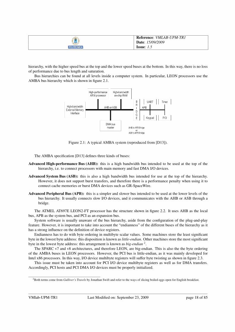


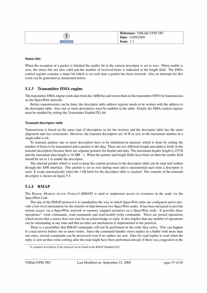


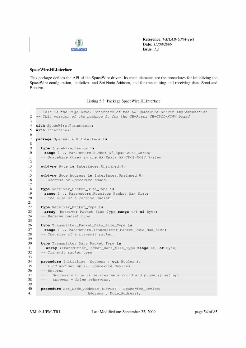

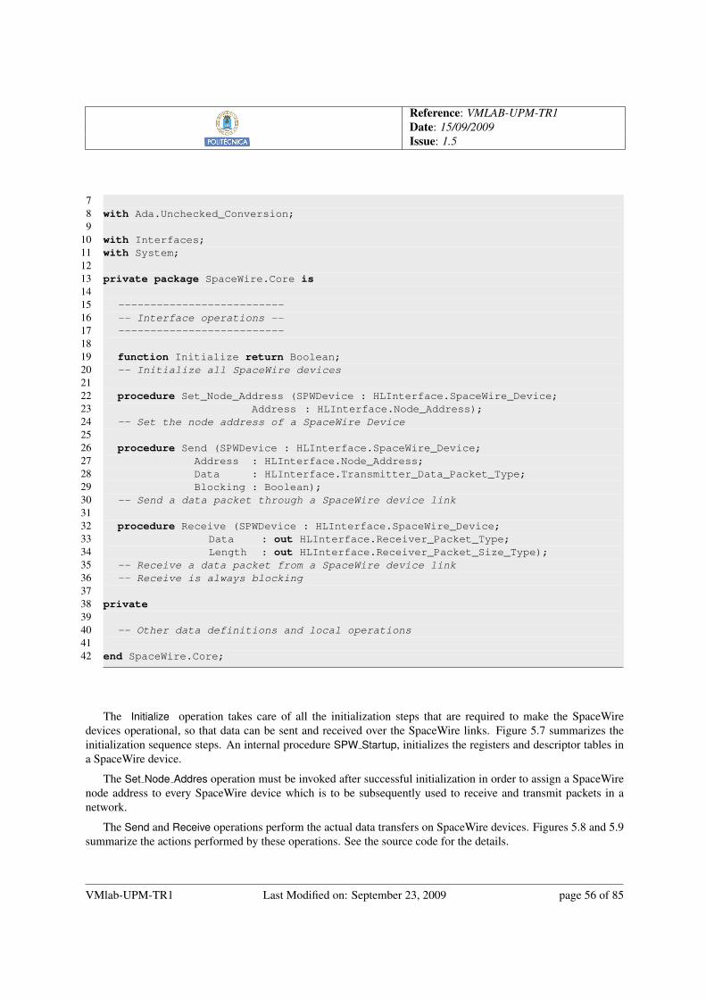


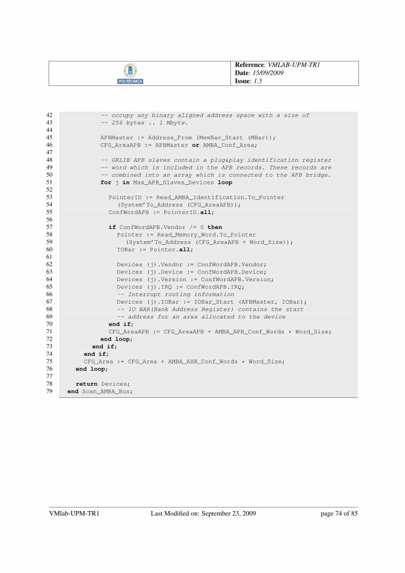


![ESTEC Contract No. xxxxxxxxxx with [Contractor ...otri.us.es/otri/documentacion/convocatorias-internacional/Modelo de... · ESTEC Contract No. xxxxxxxxxx . with [Contractor] ... The](https://static.documents.pub/doc/80x56/5a9e6e1c7f8b9a6c178b5b53/estec-contract-no-xxxxxxxxxx-with-contractor-otriusesotridocumentacionconvocatorias-internacionalmodelo.jpg)


