37
University of Azad Jammu & Kashmir Muzaffarabad Institute of Geology

University of Azad Jammu & Kashmir Muzaffarabad
Institute of Geology

Topic
Estimation of initial Stresses
Initial stressStress state in rock mass without artificial disturbances.
One of the basic data in designing rock structure.
Competence factor = Uniaxial compressive stress / initialvertical stress is a good index for stability of an opening in
rock mass
Initial stress
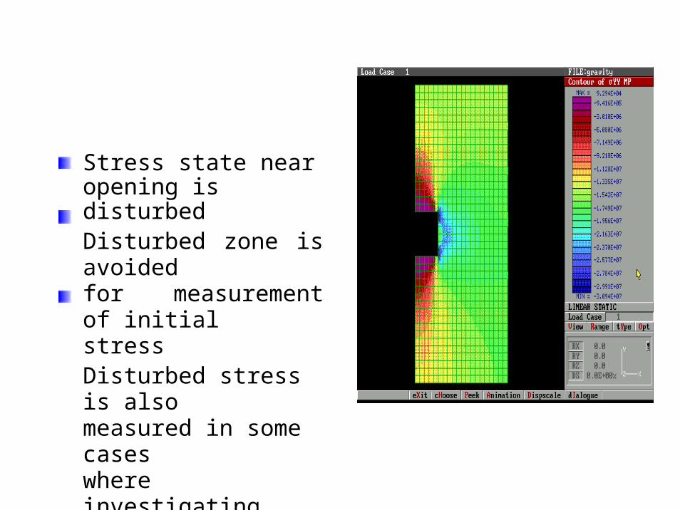
Stress state near opening isdisturbedDisturbed zone is avoided for measurement of initial stressDisturbed stress is also measured in some cases where investigating deformation and failure behavior around the opening

Primitive Estimation
σ V = γ h
stress σV
is
weight of rock
Initial verticalequal to theoverburden(overburden pressure)
γ is unit volume weight(ex. 27 kN /m3 )h is the depth (m)
Ex. Initial vertical stress at 500 m deep is 13.5MPa
σ V = γ h
σ h = k2σ V
σ H
= k1σ V
Initial stress value
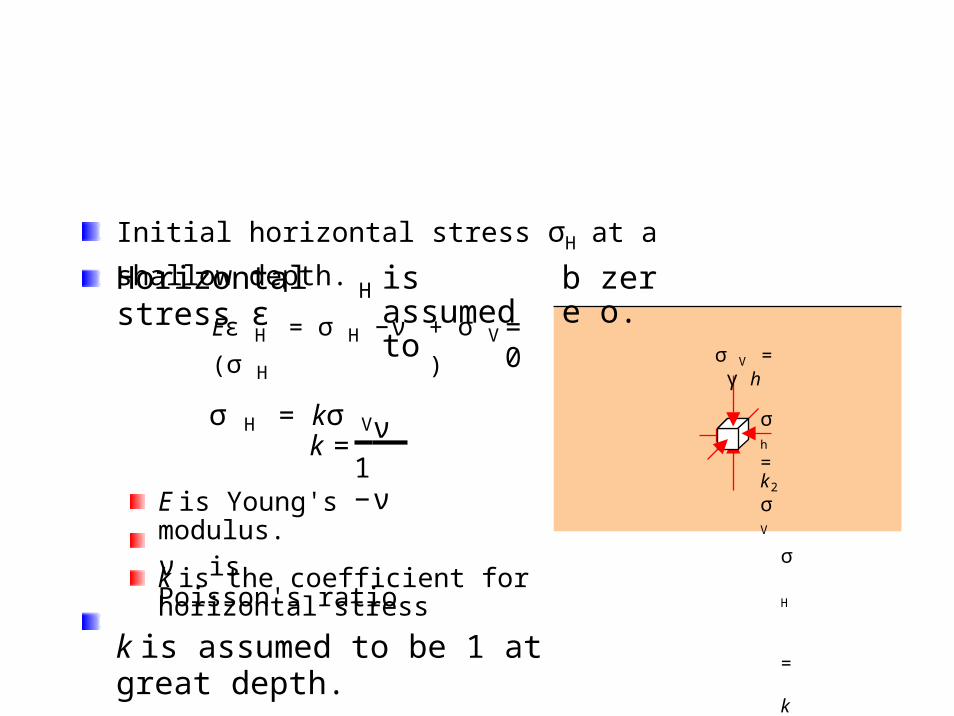
Initial horizontal stress σH at a shallow depth.
Horizontal stress ε is assumed to be zero.H
Eε H = σ H −ν (σ H
σ H = kσ V
+ σ V ) = 0
ν k =
1 −νE is Young's modulus.ν is Poisson's ratio
k is the coefficient for horizontal stress
k is assumed to be 1 at great depth.
σ V = γ h
σ h
= k2
σ V
σ H
= k1
σ V
Measured initial stress values
Initial verticalstress is roughly equal to the primitive estimation
Initial horizontalstress is different from the primitive estimation
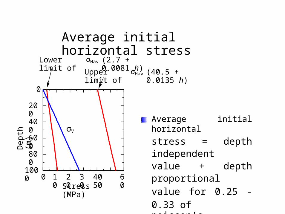
Average initial horizontal stress
σHavLower limit of (2.7 + 0.0081 h)
σHavUpper limit of (40.5 + 0.0135 h)
0
200
Average initial horizontal
stress = depth independent value + depth proportional value for 0.25 - 0.33 ofpoisson's ratio
400
600
800
10000 10 20 30 40 50 60
Stress (MPa)
Dep
th (
m)
σV

Depth independent value?
Movement of the tectonic platesSpherical shell subsidence model
"Reprinted from http://pubs.usgs.gov/gip/earthq1/fig1.gif with permission from USGS".
Orientation of the maximum horizontal stress measured byhydraulic fracture method (Goodman, 1980)
Average focalmechanism of deep earthquakes in and around Japan projected on the upper hemisphere. Arrows show tension and compression axes (Kasahara, 1983)
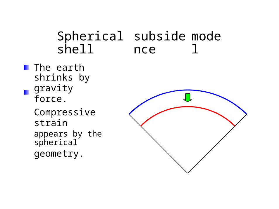
Spherical shell subsidence model
The earth shrinks bygravity force.
Compressive strainappears by the spherical
geometry.
Need for initial stress measurement
Initial stress can roughly estimated by the primitivemethod
Measurement is required for precise valuesInitial stress can be affected by such geological phenomena as fold, faults, intrusion of magma etc.
Method to measure initial stress
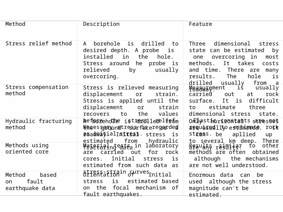
Method Description Feature
Stress relief method A borehole is drilled to desired depth. A probe is installed in the hole. Stress around he probe is relieved by usually overcoring.
Three dimensional stress state can be estimated by one overcoring in most methods. It takes costs and time. There are many results. The hole is drilled usually from a roadway.
Stress compensation method Stress is relieved measuring displacement or strain. Stress is applied until the displacement or strain recovers to the values before the stress relief. Necessary stress is regarded as initial stress.
Measurement is usually carried out at rock surface. It is difficult to estimate three dimensional stress state. Elastic constants are not required to estimate rock stress.
Hydraulic fracturing method A borehole is drilled from the ground surface or a roadway. Initial stress is estimated from hydraulic fracturing data.
Only horizontal stresses are usually estimated. It can be apllied up to several km deep. There are any results.
Methods using oriented core Material tests in laboratory are carried out for rock cores. Initial stress is estimated from such data as stress-strain curves.
Results similar to other methods are often obtained although the mechanisms are not well understood.
Method based on fault earthquake data
Orientation of initial stress is estimated based on the focal mechanism of fault earthquakes.
Enormous data can be used although the stress magnitude can't be estimated.
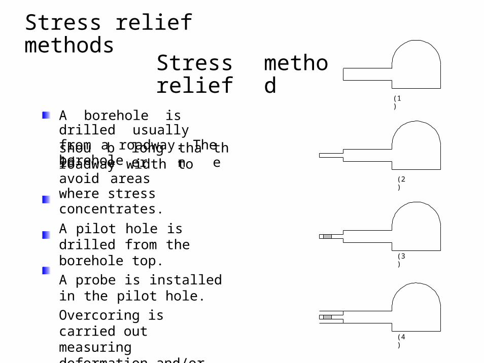
Stress relief method
(1)
A borehole is drilled usuallyfrom a roadway. The boreholeshould be longer than theroadway width to avoid areaswhere stress concentrates.
A pilot hole is drilled from the borehole top.
A probe is installed in the pilot hole.
Overcoring is carried out measuring deformation and/or strains.
(2)
(3)
(4)
Stress relief methods
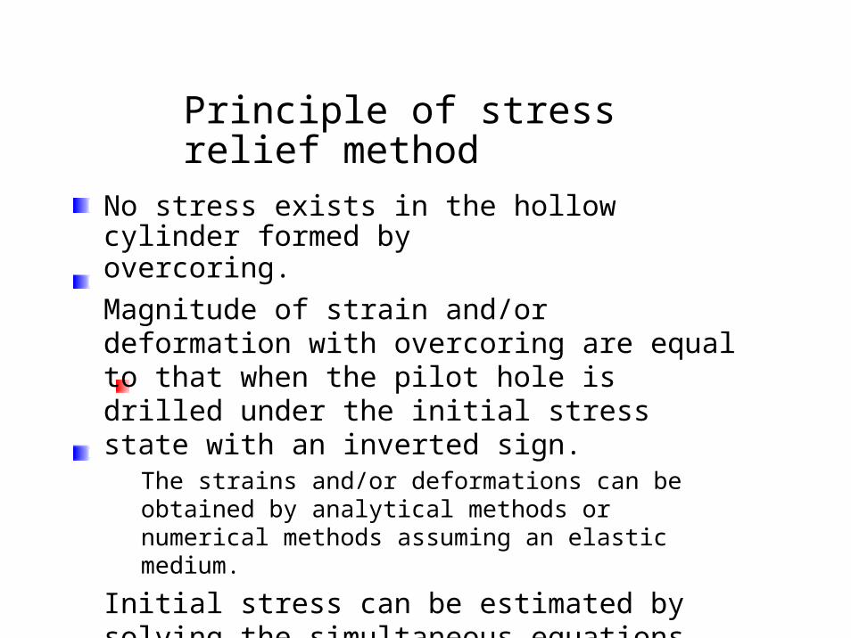
Principle of stress relief method
No stress exists in the hollow cylinder formed byovercoring.
Magnitude of strain and/or deformation with overcoring are equal to that when the pilot hole is drilled under the initial stress state with an inverted sign.
The strains and/or deformations can be obtained by analytical methods or numerical methods assuming an elastic medium.
Initial stress can be estimated by solving the simultaneous equations.

Example
2y
1
Overcoring
σ α = σ cos 2 α + σ sin 2 α + 2τ xycosα sin α
x y
x
3A rosette gage was atacched to a rock surface and overcoring was carried out around the gage. Represent change in strains of the gauges 1, 2 and 3 by E, ν, σx, σy τxy.
Conical bottom strainmethod (Sakaguchi et al.,1994)

Hydraulic fracturing method
Often used method.
Originally developed for wells for petroleum and geothermal energy to measure stress and to enhance the prodcution
Fracture
There are some cases inwhich hydraulic fracturing
pis carried out from anexisted roadway.
Packer
Hydraulic fracturing
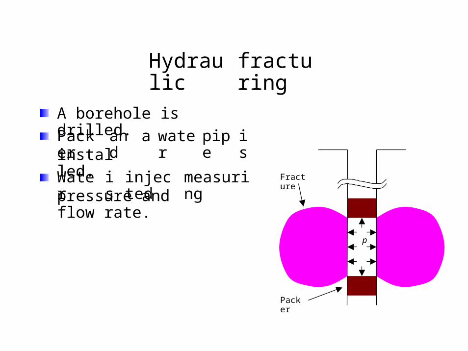
Hydraulic fracturing
A borehole is drilled.
Packer and a water pipe isinstalled.
Water is injected measuring Fracture
pressure and flow rate.
p
Packer

Hydraulic fracturingWater valve is closed afterbreakdown which is a decrease ofwater pressure and represents that afracture appears at the borehole wall.
BreakdownThe pressure at the breadown iscalled pb.
Water is injected again.Decrease of the slope of the water
pb
pr
Down-hole pressureps
pressure-time curve representreopening, namely, the fracture isopened again. The pressure at re-openingpressure pr.
is called re-opening
Injectionand then pressure
is continued for a whilethe valve is shut.Water
Flow rate
will converge. Theconverged pressure is called shut-inpressure ps.
Time
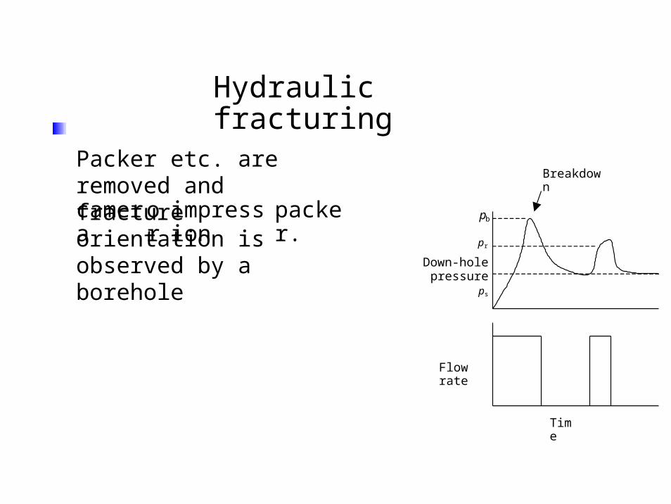
Hydraulic fracturingPacker etc. are removed and fracture orientation is observed by a borehole Breakdown
camera or impression packer. pb
pr
Down-hole pressureps
Flow rate
Time
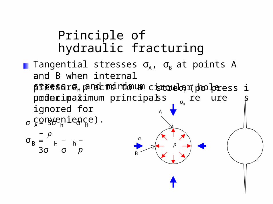
Principle of hydraulic fracturing
Tangential stresses σA, σB at points A and B when internal
pressure p acts to a circular hole under maximum principalstress σH and minimum principal
ignored for convenience).σh
σ
stress (pore pressure is
H
A
σ A
σ
= 3σ h − σ H − p
σh= 3σ − σ − pB H h p
B

principle of hydraulicfracturing
σA is smaller than σB. A
fracture initiate and grows from point A
when the following criterion satisfied.
T0 is tensile strength.
is
σH
A
T0 ≤ −σ A = −3σ h + σ H + p
σh
The following equation is derived for the breakdownpressure pb.
T0 = −3σ h + σ H + pb
p
B
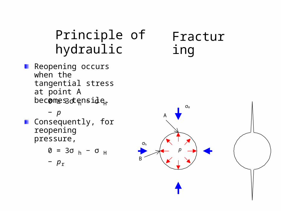
Principle of hydraulic Fracturing
Reopening occurs when thetangential stress at point Abecomes tensile.
0 ≥ 3σ h − σ H − pσH
AConsequently, for reopeningpressure,
σh
0 = 3σ h − σ H − prp
B
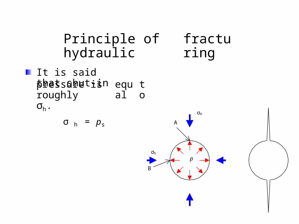
Principle of hydraulic fracturing
It is said that shut-inpressure is roughlyσh.
σ h = ps
equal to
σH
A
σh
p
B
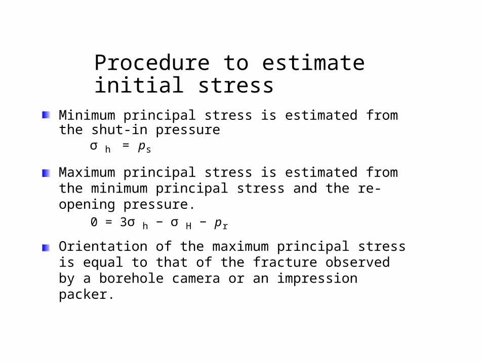
Procedure to estimate initial stress
Minimum principal stress is estimated from the shut-in pressure
σ h = ps
Maximum principal stress is estimated from the minimum principal stress and the re-opening pressure.
0 = 3σ h − σ H − pr
Orientation of the maximum principal stress is equal to that of the fracture observed by a borehole camera or an impression packer.
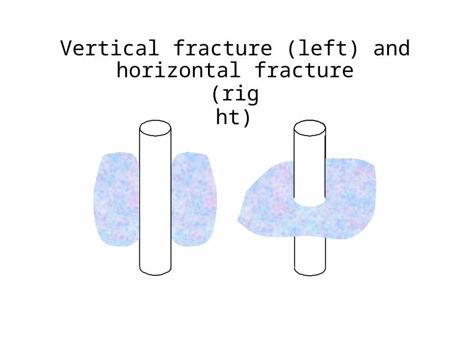
Vertical fracture (left) and horizontal fracture(right)
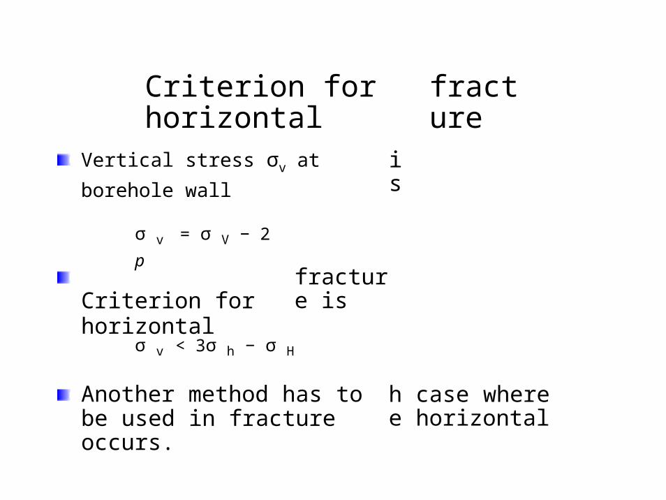
Criterion for horizontal fracture
Vertical stress σv at borehole wall is
σ v = σ V − 2 p
Criterion for horizontal fracture is
σ v < 3σ h − σ H
Another method has to be used in fracture occurs.
he case where horizontal
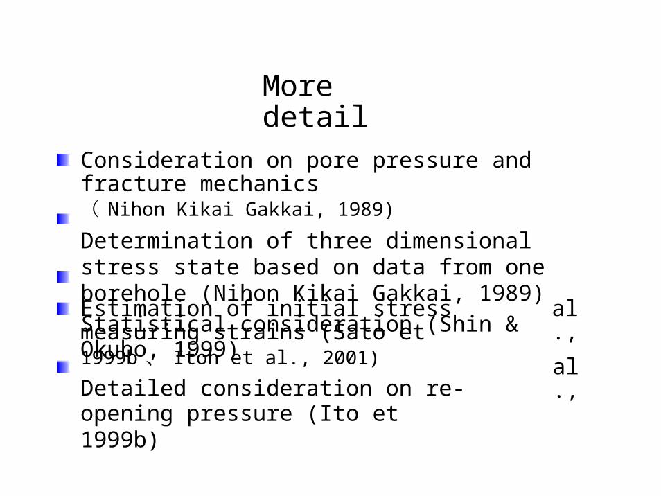
More detail
Consideration on pore pressure and fracture mechanics( Nihon Kikai Gakkai, 1989)
Determination of three dimensional stress state based on data from one borehole (Nihon Kikai Gakkai, 1989)
Statistical consideration (Shin & Okubo, 1999)
Estimation of initial stress measuring strains (Sato et1999b 、 Itoh et al., 2001)
Detailed consideration on re-opening pressure (Ito et1999b)
al.,
al.,
Example
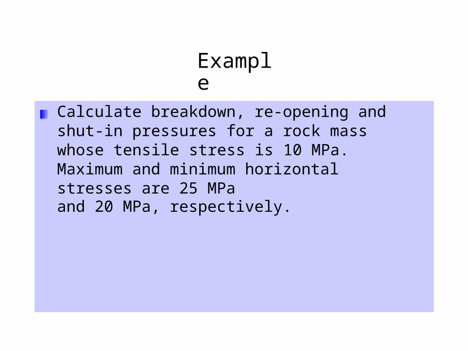
Calculate breakdown, re-opening and shut-in pressures for a rock mass whose tensile stress is 10 MPa. Maximum and minimum horizontal stresses are 25 MPaand 20 MPa, respectively.
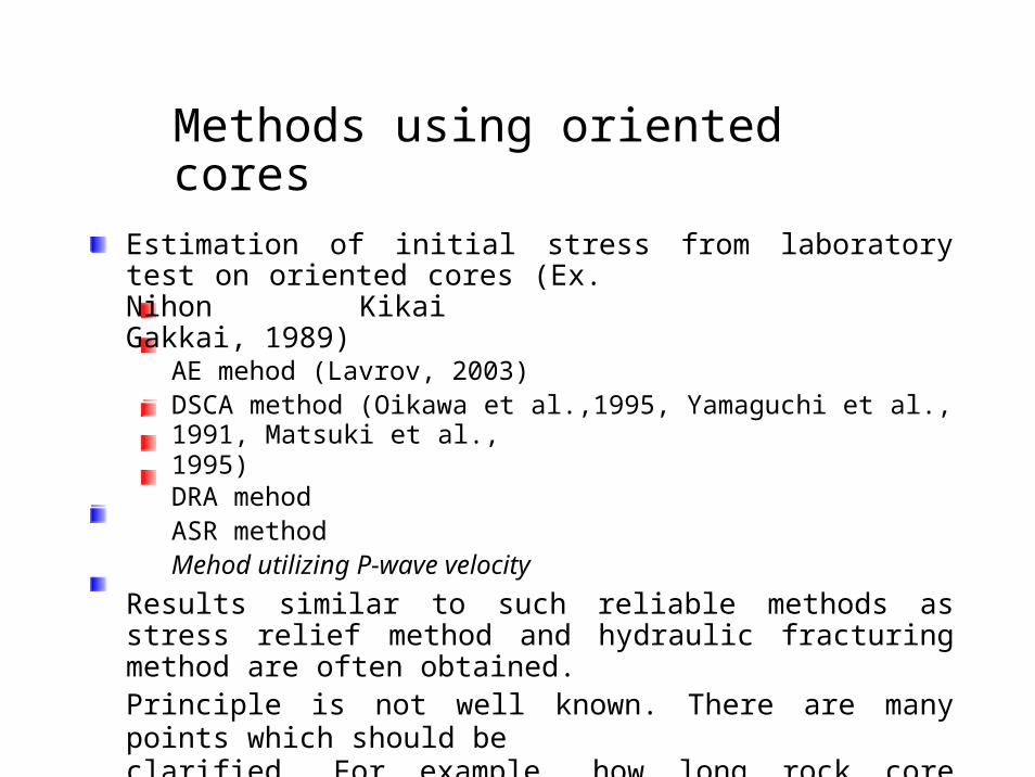
Estimation of initial stress from laboratory test on oriented cores (Ex.Nihon Kikai Gakkai, 1989)
AE mehod (Lavrov, 2003)DSCA method (Oikawa et al.,1995, Yamaguchi et al., 1991, Matsuki et al.,1995)DRA mehodASR methodMehod utilizing P-wave velocity
Results similar to such reliable methods as stress relief method and hydraulic fracturing method are often obtained.Principle is not well known. There are many points which should be clarified. For example, how long rock core maintain the stress memory is not well known.
Methods using oriented cores
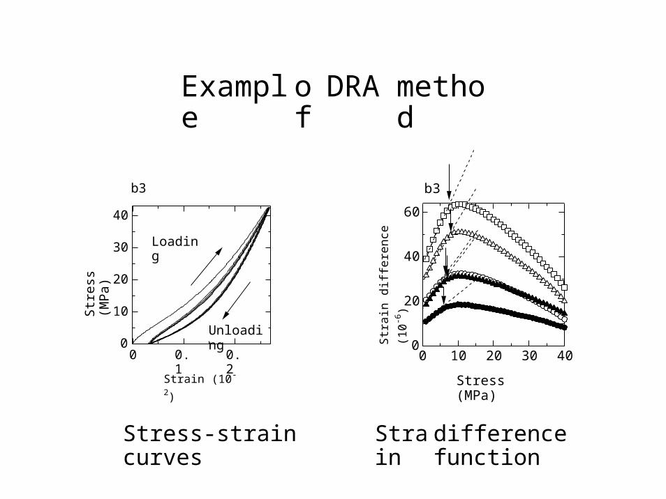
Example of DRA method
b3 b3
6040
Loading3040
20
2010
0 00 0.1 0.2 0 10 20 30 40
Strain (10-2) Stress (MPa)
Stress-strain curves Strain difference function
Str
ess
(MP
a)
Str
ain
diffe
renc
e (1
0-6
)
Unloading
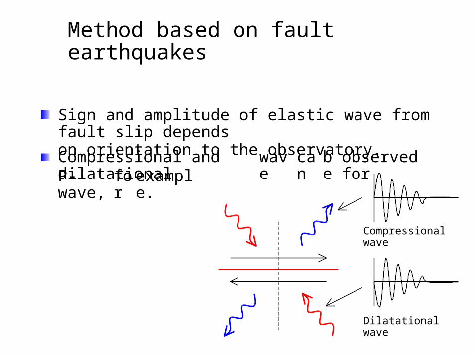
Sign and amplitude of elastic wave from fault slip dependson orientation to the observatory.
Compressional and dilatational wave can be observed forP-wave, for example.
Compressional wave
Dilatational wave
Method based on fault earthquakes
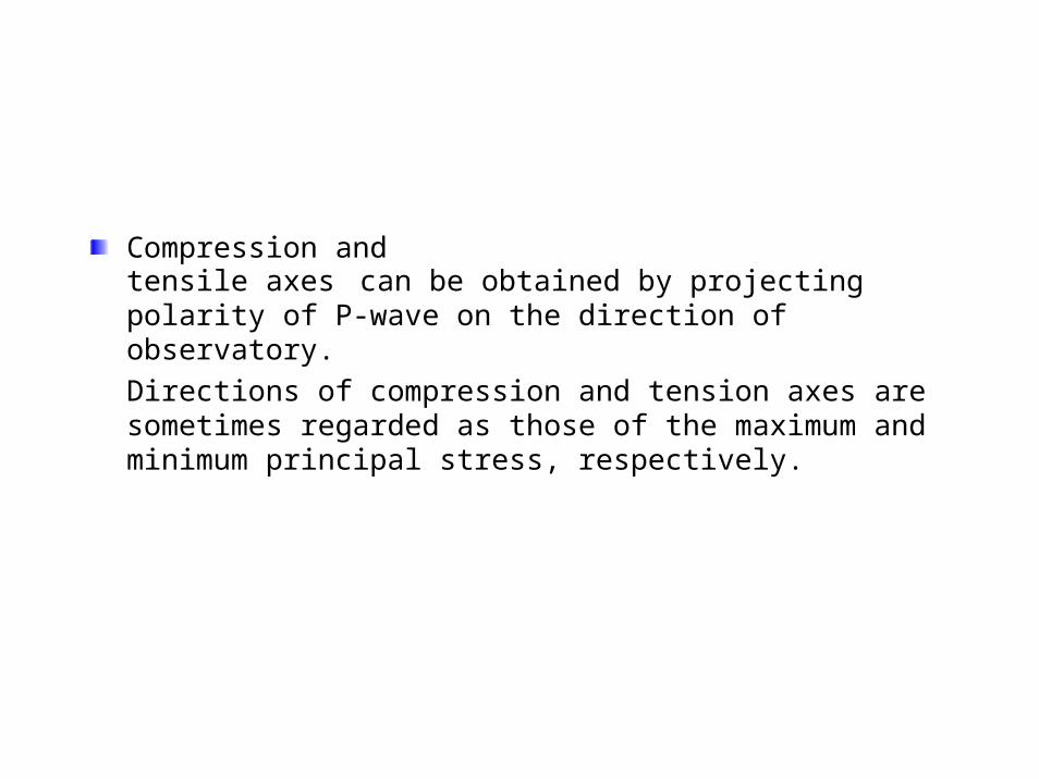
Compression andtensile axes can be obtained by projecting polarity of P-wave on the direction of observatory.
Directions of compression and tension axes are sometimes regarded as those of the maximum and minimum principal stress, respectively.

Compression and tension axes represents stress change dueto fault slip and their directions should not be always coincides to those of initial stress. However, similar results to stress relief method and hydraulic fracturing method are often obtained.
The directions of initial stress can be easily estimated from enormous fault earthquake data although the magnitude of initial stress can't be estimated.
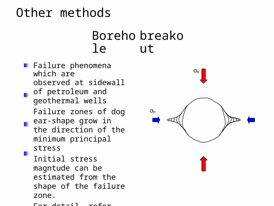
Borehole breakout
Failure phenomena which areobserved at sidewall of petroleum and geothermal wells
Failure zones of dog ear-shape grow in the direction of the minimum principal stress
Initial stress magntude can be estimated from the shape of the failure zone.
For detail, refer Brudy & Zoback (1999), Cuss et al. (2003), Haimson & Lee (2004)
σH
σh
Other methods

Core discing
Rock core breaks in amany discs when a borehole is drilled to a high pressure zone.
Relationship between stress state and disc shape is investigated (ex. Obara et al., 1998).
Initial stress state can be roughly estimated.
Core discing which wasobserved at Kamaishi Mine
Other other other
Calcite twins ( Kang et al., 1999 )Sub-crater of volcano (Karino and Murata,
1998 ) Electric resistivity (Ito et al., 1999a ) etc.........................


