155
EstiNet L2/SDN Switch Web User Interface USER GUIDE
| Date post: | 16-May-2019 |
| Category: |
Documents |
| Upload: | dinhnguyet |
| View: | 221 times |
| Download: | 0 times |
EstiNet L2/SDN Switch Web User Interface
USER GUIDE

Table of Contents
1 Introduction ................................................................ 1 2 Status ...................................................................... 3
2.1 System Information .................................................. 3 2.2 Logging Message ..................................................... 5 2.3 Port ................................................................ 6
2.3.1 Port Statistics ................................................. 6 2.3.2 Port Error Disabled ............................................. 8
2.4 PoE Status .......................................................... 9 2.5 Link Aggregation ................................................... 10 2.6 MAC Address Table .................................................. 11
3 Network .................................................................... 12 3.1 IP Address ......................................................... 12 3.2 System Time ........................................................ 14
4 SDN ........................................................................ 16 4.1 SDN Setting ........................................................ 16
5 Port ....................................................................... 18 5.1 Port Setting ....................................................... 18 5.2 Error Disabled ..................................................... 20 5.3 Link Aggregation ................................................... 21
5.3.1 LAG Group ...................................................... 21 5.3.2 LAG Port Setting ............................................... 23 5.3.3 LACP Setting ................................................... 25
5.4 EEE ................................................................ 26 5.5 Jumbo Frame ........................................................ 27 5.6 PoE ................................................................ 28
5.6.1 PoE Port Status ................................................ 28 5.6.2 PoE Setting .................................................... 29
6 VLAN ....................................................................... 30 6.1 VLAN ............................................................... 30
6.1.1 Create VLAN .................................................... 30 6.1.2 VLAN Configuration ............................................. 31 6.1.3 VLAN Membership ................................................ 32 6.1.4 Port Setting ................................................... 34
6.2 Protocol VLAN ...................................................... 36 6.2.1 Protocol Group ................................................. 36 6.2.2 Protocol VLAN Group Binding .................................... 37
6.3 GVRP ............................................................... 38 6.3.1 GVRP Property .................................................. 38 6.3.2 GVRP Membership ................................................ 40 6.3.3 GVRP Statistics ................................................ 41
7 MAC Address Table .......................................................... 42 7.1 Dynamic Address .................................................... 42 7.2 Static MAC Setting ................................................. 43 7.3 MAC Filtering Address .............................................. 44
8 Spanning Tree Protocol ..................................................... 45 8.1 STP Property ....................................................... 45 8.2 STP Port Setting ................................................... 47 8.3 MST Instance Setting ............................................... 49 8.4 MST Port Setting ................................................... 50 8.5 STP Statistics ..................................................... 51
9 Discovery .................................................................. 52 9.1 LLDP Property ...................................................... 52 9.2 LLDP Port Setting .................................................. 53 9.3 LLDP MED Network Policy Setting .................................... 55
9.4 LLDP MED Port Setting .............................................. 56 9.5 LLDP Local Information ............................................. 57 9.6 LLDP Neighbor ...................................................... 60 9.7 LLDP Statistics .................................................... 61
10 Multicast .................................................................. 62 10.1 General ............................................................ 62
10.1.1 Multicast Property ............................................. 62 10.1.2 Multicast Group Address ........................................ 63 10.1.3 Multicast Router Port .......................................... 64 10.1.4 Multicast Forward All .......................................... 66 10.1.5 Multicast Throttling ........................................... 68 10.1.6 Multicast Filtering Profile .................................... 69 10.1.7 Multicast Filtering Binding .................................... 70
10.2 IGMP Snooping ...................................................... 71 10.2.1 IGMP Property .................................................. 71 10.2.2 IGMP Querier Setting ........................................... 74
10.3 MLD Snooping ....................................................... 75 10.3.1 MLD Snooping Property .......................................... 75 10.3.2 MLD Snooping Statistics ........................................ 77
10.4 MVR ................................................................ 78 10.4.1 MVR Property ................................................... 78 10.4.2 MVR Port Setting ............................................... 79 10.4.3 MVR Group Address .............................................. 80
11 Security ................................................................... 81 11.1 RADIUS Server ...................................................... 81 11.2 TACACS+ Server ..................................................... 83 11.3 AAA ................................................................ 85
11.3.1 AAA Method List ................................................ 85 11.3.2 AAA Login Authentication. ...................................... 87
11.4 Management Access .................................................. 88 11.4.1 Management VLAN ................................................ 88 11.4.2 Management Service ............................................. 89 11.4.3 Management ACL ................................................. 91 11.4.4 Management ACE ................................................. 92
11.5 Authentication Manager ............................................. 94 11.5.1 Authentication Manager Property ................................ 94 11.5.2 Authentication Port Setting .................................... 96 11.5.3 MAC-Based Local Account ........................................ 98 11.5.4 Web-Based Local Account ........................................ 99 11.5.5 Sessions ...................................................... 100
11.6 Port Security ..................................................... 101 11.7 Protected Ports ................................................... 102 11.8 Storm Control ..................................................... 103 11.9 DoS ............................................................... 105
11.9.1 Dos Property .................................................. 105 11.9.2 Dos Port Setting .............................................. 107
11.10 Dynamic ARP Inspection ............................................ 108 11.10.1 DAI property .................................................. 108 11.10.2 Dynamic ARP Inspection Statistics ............................. 110
11.11 DHCP Snooping ..................................................... 111 11.11.1 Property ...................................................... 111 11.11.2 Statistics .................................................... 113 11.11.3 Option82 Property ............................................. 114 11.11.4 Option82 Circuit ID Setting ................................... 116
12 QoS ....................................................................... 117 12.1 Rate Limit ........................................................ 117
13 Diagnostics ............................................................... 118 13.1 Logging ........................................................... 118

13.1.1 Logging Property .............................................. 118 13.1.2 Remote Server ................................................. 120
13.2 Mirroring Setting ................................................. 121 13.3 Ping .............................................................. 123 13.4 Traceroute ........................................................ 124 13.5 Copper Test ....................................................... 125 13.6 Fiber Module ...................................................... 126 13.7 UDLD .............................................................. 127
13.7.1 UDLD Property ................................................. 127 13.7.2 UDLD Neighbor ................................................. 128
14 Management ................................................................ 129 14.1 User Account ...................................................... 129 14.2 Firmware .......................................................... 130
14.2.1 Upgrade/Backup ................................................ 130 14.3 Configuration ..................................................... 131
14.3.1 Upgrade/Backup ................................................ 131 14.3.2 Save Configuration ............................................ 133
14.4 SNMP .............................................................. 134 14.4.1 SNMP View ..................................................... 134 14.4.2 SNMP Group .................................................... 135 14.4.3 SNMP Community ................................................ 137 14.4.4 SNMP User ..................................................... 138 14.4.5 SNMP Engine ID ................................................ 140 14.4.6 SNMP Trap Event ............................................... 141 14.4.7 SNMP Notification ............................................. 142
14.5 RMON .............................................................. 144 14.5.1 RMON Statistics ............................................... 144 14.5.2 RMON History .................................................. 146 14.5.3 RMON Event .................................................... 148 14.5.4 RMON Alarm .................................................... 150

1
1 Introduction
EstiNet managed switch software provides layer 2 and SDN functionalities for
enterprise networks. This guide describes how to use Web-based management interface
(Web UI) to configure EstiNet managed switch software features.
The Web UI supports all frequently used web browsers listed below:
Microsoft Internet Explorer 8 (and later versions)
Mozilla Firefox 3.5 and (and later versions)
Google Chrome 9.0 and (and later versions)
The Switch default URL address for Management Web UI is http://192.168.1.1. The
default username is “switch” and the default password is “admin”.
Figure 1-1 Web Login page
On the top of Web UI page, the left column shows the switch configuration menu. The
switch panel shows the switch’s current link status. Green squares indicate the port
link is up, while black squares indicate the port link is down. Below the switch panel
is the System Information table that shows basic system information of the switch.
Note: At first time setup user need to re-configure the IP address and subnet mask of
the PC, in order to let PC can access to the switch.
Here is the detail procedures to re-configure the IP address, subnet mask of the PC.
a. Press “Start” > “Control Panel”; choose to view Network Connections b. Choose “Local Area Connection”, click right button then choose the “Properties” c. Choose “Networking” tab, choose the “Internet Protocol Version 4(TCP/IPv4)”, and
then click “Properties”. Please need to remember the original IP setting.
d. Press “General” for manually setup the IP address. e. For the IP address field please input the IP address which is the same subnet as
the switch; for example:192.168.1.2
f. Please input 255.255.255.0 to the subnet mask, then press OK.
Initiate the PC WEB browser then input the default URL http://192.168.1.1 for
accessing the switch to do the configuration. Once the switch finished the
configuration it can get the assigned IP address through the DHCP server. After the
successful switch setting administrator need to roll back the original IP address for
connecting to the network.

2
Figure 1-2 Web User Interface

3
2 Status
Use the Status pages to view system information and status.
2.1 System Information To display System Information web page, click Status > System Information.
Use this page to configure System related information and browse some system
information such as MAC address, IP address, firmware version, loader version …… etc.
Figure 2-1 System Information page

4
With “Edit” button in the table,user could configure the field value.
Field Description
System Name System name of the switch.
System Location System location of the switch.
System Contact System contact of the switch
Table 2-1 System Information fields

5
2.2 Logging Message To view the logging messages stored on the RAM and Flash, click Status > Logging
Message.
Figure 2-2 Logging Message page
Field Description
Viewing View the logging information stored on switch memory.
RAM: Show the logging messages stored on the RAM.
Flash: Show the logging messages stored on the Flash.
Showing entries How many entries will be showed on a single page:
Possible value: ALL, 10, 30, 50, 100.
Table 2-2 Logging Message fields

6
2.3 Port The Port configuration page displays port summary and status information.
2.3.1 Port Statistics To display Port Counters web page, click Status > Port > Statistics.
This page displays standard counters on network traffic form the Interfaces, Ethernet-
like and RMON MIB. Interfaces and Ethernet-like counters display errors on the traffic
passing through each port. RMON counters provide a total count of different frame types
and sizes passing through each port. The “Clear” button will clear MIB counter of current
selected port.
Figure 2-3 Port Statistics page

7
Figure 2-4 Port Statistics page
Field Description
Port Select one port to show counter statistics.
MIB Counter Select the MIB Counter to show different counter type.
All: All counters.
Interface: Interface related counters.
Etherlike: Ethernet-like related counters.
RMON: RMON related counters.
Refresh Rate Select refresh rate of the counter table.
Table 2-3 Port Statistics fields
8
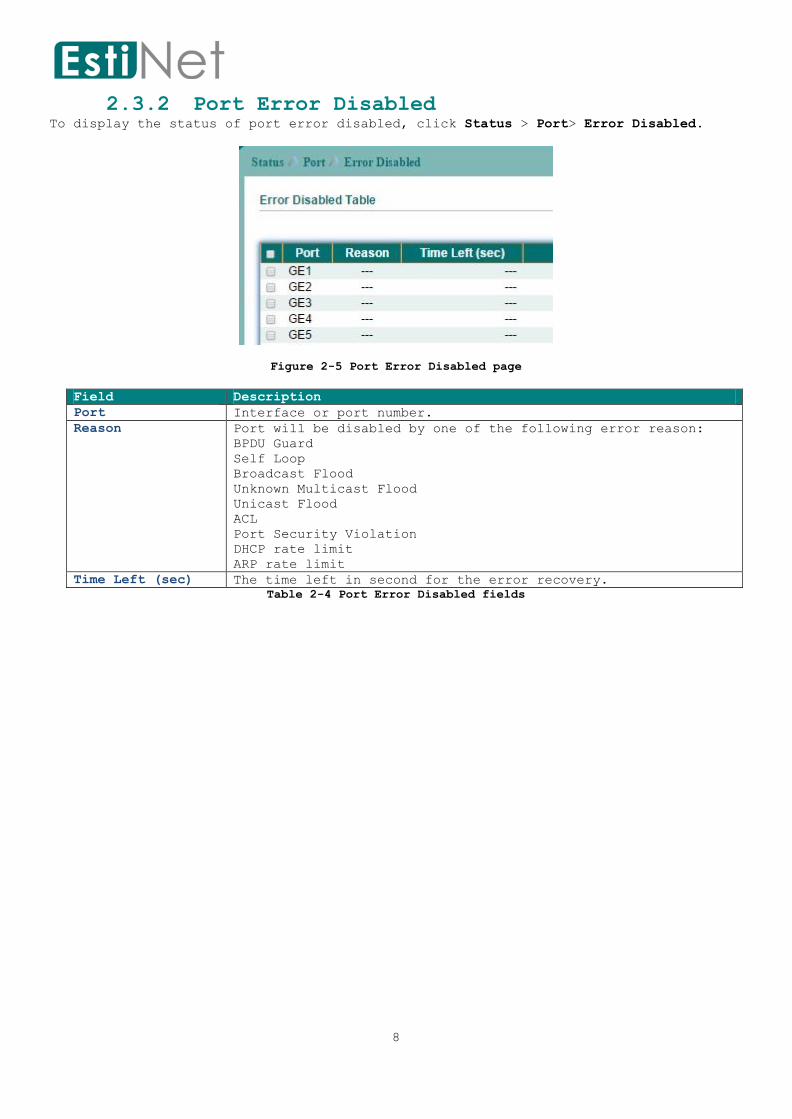
2.3.2 Port Error Disabled To display the status of port error disabled, click Status > Port> Error Disabled.
Figure 2-5 Port Error Disabled page
Field Description
Port Interface or port number.
Reason Port will be disabled by one of the following error reason:
BPDU Guard
Self Loop
Broadcast Flood
Unknown Multicast Flood
Unicast Flood
ACL
Port Security Violation
DHCP rate limit
ARP rate limit
Time Left (sec) The time left in second for the error recovery.
Table 2-4 Port Error Disabled fields

9
2.4 PoE Status To display PoE Status web page, click Status > PoE Status.
Figure 2-6 PoE Status page
Field Description
PoE Mode The mode of the PoE:
Static : static mode with user configured power.
Dynamic : automatically allocated power base on the link-
up sequence of PD device.
Total Power(W) The total power budget.
Allocated Power(W) The used power.
Remaining Power(W) The remain power.
Table 2-5 PoE Status fields
10
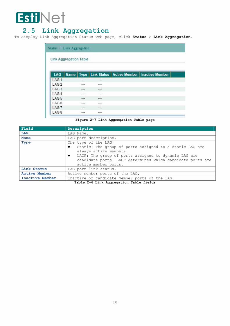
2.5 Link Aggregation To display Link Aggregation Status web page, click Status > Link Aggregation.
Figure 2-7 Link Aggregation Table page
Field Description
LAG LAG Name.
Name LAG port description.
Type The type of the LAG:
Static: The group of ports assigned to a static LAG are
always active members.
LACP: The group of ports assigned to dynamic LAG are
candidate ports. LACP determines which candidate ports are
active member ports.
Link Status LAG port link status.
Active Member Active member ports of the LAG.
Inactive Member Inactive or candidate member ports of the LAG.
Table 2-6 Link Aggregation Table fields
11
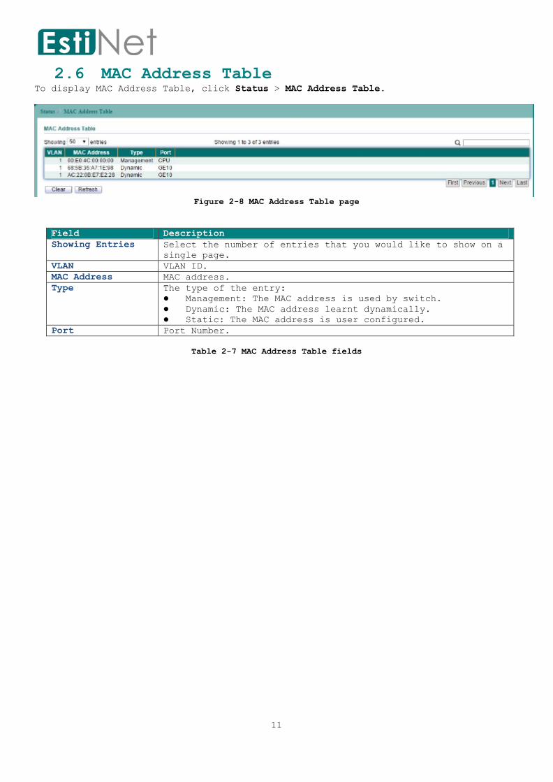
2.6 MAC Address Table To display MAC Address Table, click Status > MAC Address Table.
Figure 2-8 MAC Address Table page
Field Description
Showing Entries Select the number of entries that you would like to show on a
single page.
VLAN VLAN ID.
MAC Address MAC address.
Type The type of the entry:
Management: The MAC address is used by switch.
Dynamic: The MAC address learnt dynamically.
Static: The MAC address is user configured.
Port Port Number.
Table 2-7 MAC Address Table fields
12
3 Network
Use the Network pages to configure settings for the switch network interface and how
the switch connects to a remote server to get services.
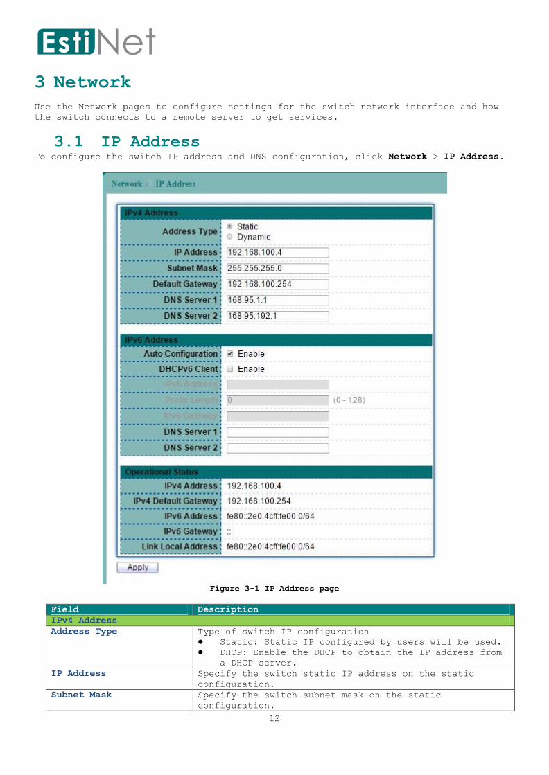
3.1 IP Address To configure the switch IP address and DNS configuration, click Network > IP Address.
Figure 3-1 IP Address page
Field Description
IPv4 Address
Address Type Type of switch IP configuration
Static: Static IP configured by users will be used.
DHCP: Enable the DHCP to obtain the IP address from
a DHCP server.
IP Address Specify the switch static IP address on the static
configuration.
Subnet Mask Specify the switch subnet mask on the static
configuration.

13
Default Gateway Specify the default gateway on the static configuration.
DNS Server 1 Specify the primary DNS server on the static
configuration.
DNS Server 2 Specify the secondary DNS server on the static
configuration.
IPv6 Address
Auto Configuration Enable/Disable the IPv6 auto configuration.
DHCPv6 Client Enable/Disable the DHCPv6 client.
IPv6 Address Specify the IPv6 address, when the IPv6 auto
configuration is disabled.
Prefix Length Specify the IPv6 prefix length.
IPv6 Gateway Specify the IPv6 default gateway, when the IPv6 auto
configuration is disabled.
DNS Server 1 Specify the primary DNS server on the static
configuration.
DNS Server 2 Specify the secondary DNS server on the static
configuration.
Table 3-1 IP Address fields

14
3.2 System Time To display Time web page, click Network > System Time.
This page allow user to set time source, static time, time zone and daylight saving
settings. Time zone and daylight saving takes effect both static time or time from
SNTP server.
Figure 3-2 System Time page
Field Description
Source Select the Source of the system time.
SNTP: Select the radio button to enable or disable using
SNTP server.
From Computer: Switch will synchronize its system time

15
with connected management PC.
Manual Time: Specify static time. Static time take effect
if SNTP is disabled.
Time Zone Select a time zone from listing countries.
SNTP
Server Address Enter SNTP Server address.
Server Port Enter SNTP Server Port.
Interval Interval time.
Manual Time
Date Set the date (Year-Month-Day).
Time Set the time (Hour - Minute - Second).
Daylight Saving Time
Type None: Disable daylight saving time.
Recurring: Using recurring mode of daylight saving time.
Non-Recurring: Using non-recurring mode of daylight.
USA: Using daylight saving time in the United States that
starts on the second Sunday of March and ends on the
first Sunday of November.
European: Using daylight saving time in the Europe that
starts on the last Sunday in March and ending on the
last.
Offset Offset of the daylight saving.
Recurring Specify the starting and ending time of recurring daylight
saving time. This field available when selecting “Recurring”
mode.
Non-Recurring Specify the starting and ending time of non-recurring
daylight saving time. This field available when selecting
“Non-Recurring” mode.
Table 3-2 System Time fields

16
4 SDN
Use the SDN pages to configure switch SDN function. When SDN enabled, a controller can
control switches via uplink port or downlink ports to forward OpenFlow control frames
to down-level switches.
4.1 SDN Setting To display SDN Setting web page, click SDN > SDN.
This page allow user to configure SDN setting on the switch.
Figure 4-1 SDN page
Field Description
State To enable or disable Switch SDN state.
1st Controller IP
Address
Enter the first Controller IP Address.
2nd Controller IP
Address
Enter the second Controller IP Address.
Controller Port Controller IP Port to use for the OpenFlow management
connection (1-65535).
Fail Mode Select a Fail Mode to use when the switch loss of
connectivity with the controller.
Standalone: The switch will reverts to using normal
processing (Ethernet Switching).
Secure: The switch will continues operation in OpenFlow
mode, until it reconnects to the server.
Counter Mode Select a counter mode to use when bind a meter in a flow
entry.
TLS Connection To enable or disable TLS encryption for the connection with
controller.
Flow Entry Templates When creating SDN flow entries, all of its match fields
must be within a template fields set. Our system provides 3
kinds of templates for SDN flow entries.
Users must choose 2 templates for SDN flow entry from 3
templates ( MAC template, IP template, MAC_IP template)
Table 4-1 SDN fields

17
Notice: Hybrid mode and OpenFlow Management VLAN shall be able to be configured when
switch is configured as In-band mode.

18
5 Port
Use the Port pages to configure settings for the switch ports, trunk, layer 2
protocols and other switch features.
5.1 Port Setting To display Port Setting web page, click Port > Port Setting.
This page allow user to configure switch port settings and show port current status.
Check the left box to select the ports then click "Edit" button to configure port
setting.
Table 5-1 Port Setting page

19
Figure 5-1 Edit Port Setting page
Field Description
Port Selected port number(s).
Description Port description.
State Port admin state.
Enabled: Enable the port.
Speed Port speed capabilities.
Auto: Auto speed with all capabilities.
Auto-10M: Auto speed with 10M ability only.
Auto-100M: Auto speed with 100M ability only.
Auto-1000M: Auto speed with 1000M ability only.
Auto-10M/100M: Auto speed with 10M/100M abilities.
10M: Force speed with 10M ability.
100M: Force speed with 100M ability.
1000M: Force speed with 1000M ability.
Duplex Port duplex capabilities.
Auto: Auto duplex with all capabilities
Half: Auto speed with 10M and 100M ability only
Full: Auto speed with 10M/100M/1000M ability only
Flow Control Port flow control.
Enabled: Enable flow control ability.
Disabled: Disable flow control ability.
Table 5-2 Port Setting fields

20
5.2 Error Disabled
To display Error Disabled web page, click Port > Error Disabled.
Figure 5-2 Error Disabled page
Field Description
Recover
Interval
Auto recovery after this interval for error disabled port.
BPDU Guard Enabled to auto shutdown port when BPDU Guard reason occur.
This reason caused by STP BPDU Guard mechanism.
UDLD Enabled to auto shutdown port when UDLD (UniDirectional Link
Detection) reason occur.
Self Loop Enabled to auto shutdown port when Self Loop reason occur.
Broadcast Flood Enabled to auto shutdown port when Broadcast Flood reason
occur. This reason caused by broadcast rate exceed broadcast
storm control rate.
Unknown Multicast
Flood
Enabled to auto shutdown port when Unknown Multicast Flood
reason occur. This reason caused by unknown multicast rate
exceed unknown multicast storm control rate.
Unicast Flood Enabled to auto shutdown port when Unicast Flood reason occur.
This reason caused by unicast rate exceed unicast storm
control rate.
ACL Enabled to auto shutdown port when ACL shutdown port reason
occur. This reason caused packet match the ACL shutdown port
action.
Port Security
Violation
Enabled to auto shutdown port when Port Security Violation
reason occur. This reason caused by violation port security
rules.
DHCP Rate Limit Enabled to auto shutdown port when DHCP rate limit reason
occur. This reason caused by DHCP packet rate exceed DHCP rate
limit.
ARP Rate Limit Enabled to auto shutdown port when ARP rate limit reason
occur. This reason caused by DHCP packet rate exceed ARP rate
limit.
Table 5-3 Error Disabled fields

21
5.3 Link Aggregation
5.3.1 LAG Group To display LAG Group Setup page, click Port > Link Aggregation > Group.
Figure 5-3 LAG Group page
Field Description
Load Balance Algorithm Select the LAG load balance distribution algorithm.
MAC Address: Based on source and destination MAC
address for all packets
IP/MAC Address: Based on source and destination
IP addresses for IP packet, and source and
destination MAC address for non-IP packets.
Table 5-4 LAG Group fields
Select the LAG and click “Edit” button to configure LAG setting.
22
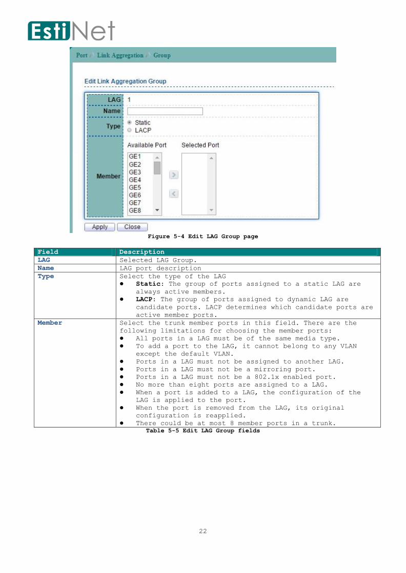
Figure 5-4 Edit LAG Group page
Field Description
LAG Selected LAG Group.
Name LAG port description
Type Select the type of the LAG
Static: The group of ports assigned to a static LAG are
always active members.
LACP: The group of ports assigned to dynamic LAG are
candidate ports. LACP determines which candidate ports are
active member ports.
Member Select the trunk member ports in this field. There are the
following limitations for choosing the member ports:
All ports in a LAG must be of the same media type.
To add a port to the LAG, it cannot belong to any VLAN
except the default VLAN.
Ports in a LAG must not be assigned to another LAG.
Ports in a LAG must not be a mirroring port.
Ports in a LAG must not be a 802.1x enabled port.
No more than eight ports are assigned to a LAG.
When a port is added to a LAG, the configuration of the
LAG is applied to the port.
When the port is removed from the LAG, its original
configuration is reapplied.
There could be at most 8 member ports in a trunk.
Table 5-5 Edit LAG Group fields

23
5.3.2 LAG Port Setting To display LAG Port Setting web page, click Port > Link Aggregation > Port Setting.
Figure 5-5 LAG Port Setting page
Field Description
LAG LAG Name.
Type Member port media type.
Description LAG port description.
Enable LAG port admin state.
Status LAG port link status.
Speed Current LAG port speed.
Duplex Current LAG port duplex.
Flow Control Current LAG port flow control state
Table 5-6 LAG Port Setting fields
Select a LAG group then click “Edit” button to configure LAG port setting.
Figure 5-6 Edit LAG Port Setting page
24
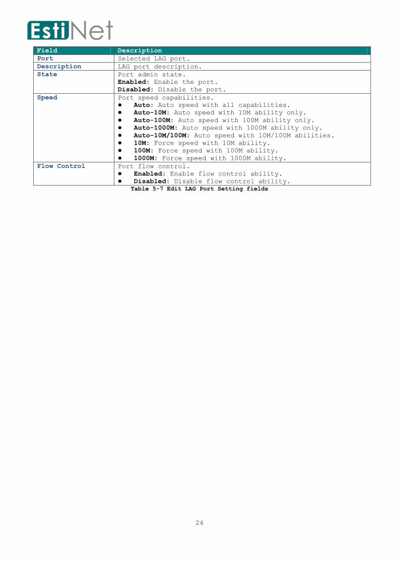
Field Description
Port Selected LAG port.
Description LAG port description.
State Port admin state.
Enabled: Enable the port.
Disabled: Disable the port.
Speed Port speed capabilities.
Auto: Auto speed with all capabilities.
Auto-10M: Auto speed with 10M ability only.
Auto-100M: Auto speed with 100M ability only.
Auto-1000M: Auto speed with 1000M ability only.
Auto-10M/100M: Auto speed with 10M/100M abilities.
10M: Force speed with 10M ability.
100M: Force speed with 100M ability.
1000M: Force speed with 1000M ability.
Flow Control Port flow control.
Enabled: Enable flow control ability.
Disabled: Disable flow control ability.
Table 5-7 Edit LAG Port Setting fields

25
5.3.3 LACP Setting
To display LACP Setting web page, click Port > Link Aggregation > LACP.
Figure 5-7 LACP page
Field Description
Entry LACP entry number.
Port LACP Port.
Port Priority The LACP priority value.
Timeout Select the periodic transmissions type of LACP PDUs.
Long: Transmit LACP PDU with slow periodic (30s).
Short: Transmit LACPP DU with fast periodic (1s).
Table 5-8 LACP fields
Select LACP port and click “Edit” button to configure LACP Port Setting.
Figure 5-8 Edit LACP page
Field Description
Port Select Select one or multiple ports to configure
Priority Enter the LACP priority value of the port
Timeout Select the periodic transmissions type of LACP PDUs.
Long: Transmit LACP PDU with slow periodic (30s).
Short: Transmit LACPP DU with fast periodic (1s).
Table 5-9 Edit LACP fields

26
5.4 EEE To configure and display the status of switch green feature, click Port > EEE.
Figure 5-9 EEE page
Select Entry number and click “Edit” button to configure EEE Setting.
Figure 5-10 Edit EEE page
Field Description
Port Selected EEE Port.
State Specify the EEE status.
Table 5-10 EEE fields

27
5.5 Jumbo Frame To modify the jumbo frame configuration, click Port > Jumbo Frame.
Figure 5-11 Jumbo Frame page
Field Description
Enable Enable Jumbo Frame.
Jumbo Frame (Bytes) Specify the size of jumbo frame. The valid range is
from 64 to 9216.
Table 5-11 Jumbo Frame fields

28
5.6 PoE
5.6.1 PoE Port Status To display PoE Port Status page, click Port > PoE > PoE Port Status.
Figure 5-12 PoE Port Status page
Field Description
Port The switch port.
Class PoE Class.
- : normal status.
Over : The used power is over the allocated power.
Consuming Power(W) The used power.
Max Power(W) Maximum power can be used.
Max Current(mA) Maximum current can be used.
Link Status The link status with PD device.
Table 5-12 PoE Port Status fields
Click “Refresh” button to update PoE Port Status.
29
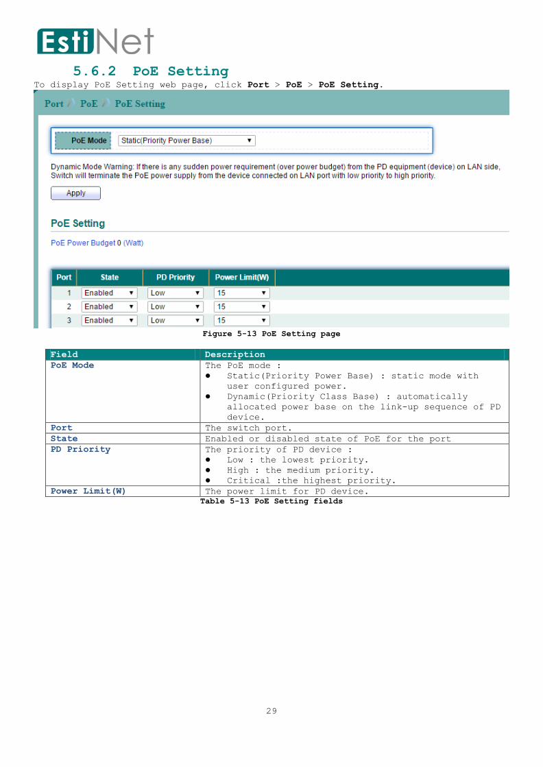
5.6.2 PoE Setting To display PoE Setting web page, click Port > PoE > PoE Setting.
Figure 5-13 PoE Setting page
Field Description
PoE Mode The PoE mode :
Static(Priority Power Base) : static mode with
user configured power.
Dynamic(Priority Class Base) : automatically
allocated power base on the link-up sequence of PD
device.
Port The switch port.
State Enabled or disabled state of PoE for the port
PD Priority The priority of PD device :
Low : the lowest priority.
High : the medium priority.
Critical :the highest priority.
Power Limit(W) The power limit for PD device.
Table 5-13 PoE Setting fields
30
6 VLAN
A virtual local area network, virtual LAN or VLAN, is a group of hosts with a common
set of requirements that communicate as if they were attached to the same broadcast
domain, regardless of their physical location. A VLAN has the same attributes as a
physical local area network (LAN), but it allows for end stations to be grouped
together even if they are not located on the same network switch. VLAN membership can
be configured through software instead of physically relocating devices or
connections.
6.1 VLAN
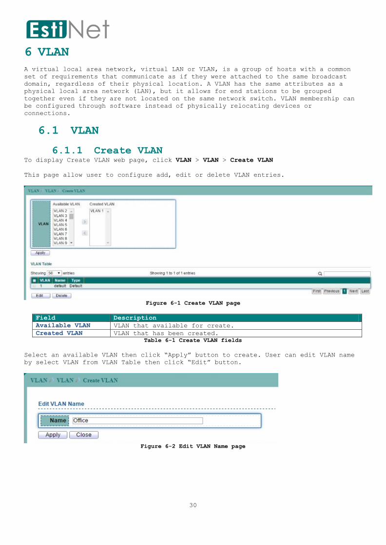
6.1.1 Create VLAN To display Create VLAN web page, click VLAN > VLAN > Create VLAN
This page allow user to configure add, edit or delete VLAN entries.
Figure 6-1 Create VLAN page
Field Description
Available VLAN VLAN that available for create.
Created VLAN VLAN that has been created.
Table 6-1 Create VLAN fields
Select an available VLAN then click “Apply” button to create. User can edit VLAN name
by select VLAN from VLAN Table then click “Edit” button.
Figure 6-2 Edit VLAN Name page
31
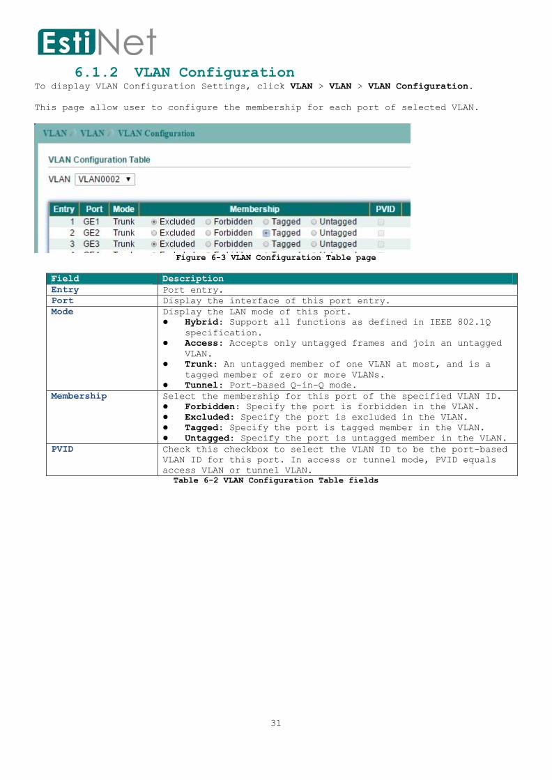
6.1.2 VLAN Configuration To display VLAN Configuration Settings, click VLAN > VLAN > VLAN Configuration.
This page allow user to configure the membership for each port of selected VLAN.
Figure 6-3 VLAN Configuration Table page
Field Description
Entry Port entry.
Port Display the interface of this port entry.
Mode Display the LAN mode of this port.
Hybrid: Support all functions as defined in IEEE 802.1Q
specification.
Access: Accepts only untagged frames and join an untagged
VLAN.
Trunk: An untagged member of one VLAN at most, and is a
tagged member of zero or more VLANs.
Tunnel: Port-based Q-in-Q mode.
Membership Select the membership for this port of the specified VLAN ID.
Forbidden: Specify the port is forbidden in the VLAN.
Excluded: Specify the port is excluded in the VLAN.
Tagged: Specify the port is tagged member in the VLAN.
Untagged: Specify the port is untagged member in the VLAN.
PVID Check this checkbox to select the VLAN ID to be the port-based
VLAN ID for this port. In access or tunnel mode, PVID equals
access VLAN or tunnel VLAN.
Table 6-2 VLAN Configuration Table fields

32
6.1.3 VLAN Membership To display Port VLAN Membership, click VLAN > VLAN > Membership.
This page allow user to view membership information for each port and edit membership
for all existed.
Figure 6-4 VLAN Membership Table page
Field Description
Entry Port entry.
Port Display the interface of this port entry.
Mode Display the VLAN mode of this port.
Administrative VLANs Display the administrative VLAN list of this port.
Operational VLANs Display the operational VLAN list of this port.
Operational VLAN means the VLAN status that really runs
in device. It may different to administrative VLAN.
Modify Click the `Edit` Button to edit the VLAN membership of
this port.
Table 6-3 VLAN Membership Table fields
Select entry and click “Edit” button to configure Port VLAN membership.
Figure 6-5 Edit VLAN Membership Port Setting page

33
Field Description
Port Selected Switch port.
Mode Display the VLAN mode of this port.
Select VLAN Select the left available VLANs to add or the right used VLANs
to delete for this port.
Tagging Select the VLAN membership of the specified left VLANs for
this port. Tagging mode may not choose in differ VLAN port
mode.
PVID Check this checkbox to select the VLAN ID to be the port-based
VLAN ID for this port. PVID may auto select or can’t select in
differ settings.
Table 6-4 Edit VLAN Membership Port Setting fields

34
6.1.4 Port Setting To display VLAN Port Setting web page, click VLAN > VLAN > Port Setting.
Figure 6-6 VLAN Port Setting page
Select entry and click “Edit” button to configure Port Setting.
Figure 6-7 Edit VLAN Port Setting page
Field Description
Port Selected Switch port.
Mode Select the VLAN port mode of the interface.
Hybrid: Support all functions as defined in IEEE 802.1Q
specification.
Access: Accepts only untagged frames and join an untagged
VLAN.
Trunk: An untagged member of one VLAN at most, and is a
tagged member of zero or more VLANs.
Tunnel: Port-based Q-in-Q mode
PVID Specify the port-based VLAN ID (1-4094). It’s only available
with Hybrid and Trunk mode.
Accepted Frame
Type
Specify the acceptable-frame-type of the specified interfaces.
It’s only available with Hybrid mode.
Ingress Filtering Specify the status of ingress filtering. It’s only available
with Hybrid mode.

35
Uplink Specify the uplink role of trunk port; it’s only available
with Trunk mode.
TPID Specify the TPID value for uplink port. It’s available with
Trunk mode when uplink enabled.
Table 6-5 Edit VLAN Port Setting fields
36
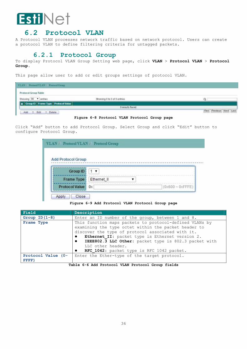
6.2 Protocol VLAN A Protocol VLAN processes network traffic based on network protocol. Users can create
a protocol VLAN to define filtering criteria for untagged packets.
6.2.1 Protocol Group To display Protocol VLAN Group Setting web page, click VLAN > Protocol VLAN > Protocol
Group.
This page allow user to add or edit groups settings of protocol VLAN.
Figure 6-8 Protocol VLAN Protocol Group page
Click “Add” button to add Protocol Group. Select Group and click “Edit” button to
configure Protocol Group.
Figure 6-9 Add Protocol VLAN Protocol Group page
Field Description
Group ID(1-8) Enter an ID number of the group, between 1 and 8.
Frame Type This function maps packets to protocol-defined VLANs by
examining the type octet within the packet header to
discover the type of protocol associated with it.
Ethernet_II: packet type is Ethernet version 2.
IEEE802.3 LLC Other: packet type is 802.3 packet with
LLC other header.
RFC_1042: packet type is RFC 1042 packet.
Protocol Value (0-
FFFF)
Enter the Ether-type of the target protocol.
Table 6-6 Add Protocol VLAN Protocol Group fields

37
6.2.2 Protocol VLAN Group Binding To display Protocol VLAN Group Binding Setting web page, click VLAN > Protocol VLAN >
Group Binding.
This page allow user to bind group to each port with VLAN ID.
Figure 6-10 Protocol VLAN Group Binding page
Click “Add” button to create a new Group Binding entry.
Figure 6-11 Add Protocol VLAN Group Binging page
Field Description
Port Select the specified ports you wish to configure by
selecting the port in this list.
Group ID Click the corresponding radio button to select a previously
configured Group ID.
VLAN Enter the VLAN ID.
Table 6-7 Add Protocol VLAN Group Binging fields
38
6.3 GVRP
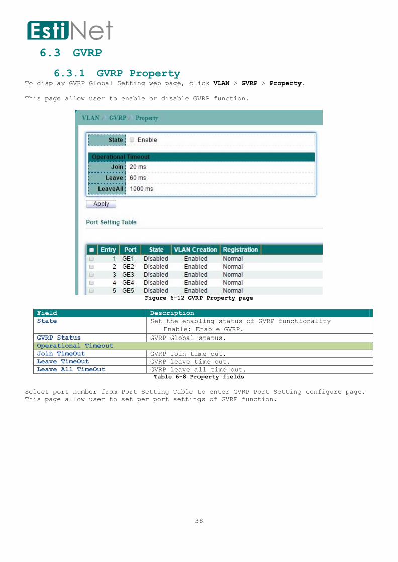
6.3.1 GVRP Property To display GVRP Global Setting web page, click VLAN > GVRP > Property.
This page allow user to enable or disable GVRP function.
Figure 6-12 GVRP Property page
Field Description
State Set the enabling status of GVRP functionality
Enable: Enable GVRP.
GVRP Status GVRP Global status.
Operational Timeout
Join TimeOut GVRP Join time out.
Leave TimeOut GVRP leave time out.
Leave All TimeOut GVRP leave all time out.
Table 6-8 Property fields
Select port number from Port Setting Table to enter GVRP Port Setting configure page.
This page allow user to set per port settings of GVRP function.

39
Figure 6-13 Edit GVRP Property Port Setting page
Field Description
Port Selected Port or multiple ports.
State Set the enabling status of GVRP port.
Enable: Enable port of GVRP.
VLAN Creation Set the enabling status of GVRP port create VLAN
Enable: port can create dynamic VLAN.
Register Set the register mode of GVRP port.
Normal: Normal mode.
Fixed: The port will not learn any dynamic VLAN.
Only send static VLAN information to neighbor and
allow static VLAN packet pass.
Forbidden: The port will not learn any dynamic
VLAN and only allow default VLAN packet pass.
Table 6-9 Edit GVRP Property Port Setting fields

40
6.3.2 GVRP Membership To display GVRP VLAN database web page, click VLAN > GVRP > Membership.
This page allow user to browser all VLAN member settings that learned by GVRP
protocol.
Figure 6-14 GVRP Membership page
Field Description
VLAN ID VLAN ID
Member Ports GVRP VLAN all port members
Dynamic Ports GVRP learned dynamic ports
Type The type of static or dynamic.
Table 6-10 GVRP Membership fields
41
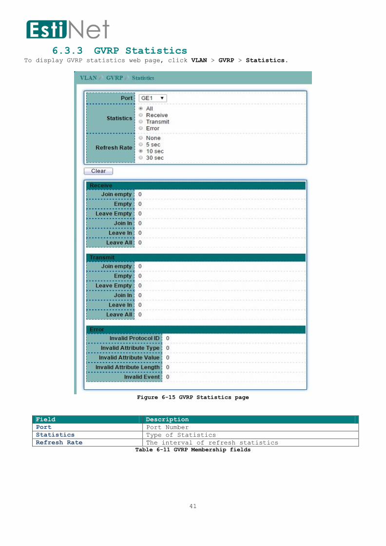
6.3.3 GVRP Statistics To display GVRP statistics web page, click VLAN > GVRP > Statistics.
Figure 6-15 GVRP Statistics page
Field Description
Port Port Number
Statistics Type of Statistics
Refresh Rate The interval of refresh statistics
Table 6-11 GVRP Membership fields

42
7 MAC Address Table
Use the MAC Address Table pages to show dynamic MAC table and configure settings for
static MAC entries.
7.1 Dynamic Address To configure the aging time of the dynamic address and to display the dynamic learned
address, click MAC Address Table > Dynamic Address.
Select the dynamic address entry and click “Add Static Address” button to configure
the entry to be static.
Figure 7-1 Dynamic Address page
Field Description
Aging Time The time in seconds that an entry remains in the MAC address
table. Its valid range is from 10 to 630 seconds, and the
default value is 300 seconds.
VLAN The VLAN ID that dynamic MAC address learned on.
MAC Address The dynamic learned MAC addresses.
Port The port number that dynamic MAC address learned on.
Table 7-1 Dynamic Address fields

43
7.2 Static MAC Setting To display the static MAC address, click MAC Address Table > Static MAC Setting.
Figure 7-2 Static Address Table page
Click “Add” button to configure new static address entry.
Figure 7-3 Add Static Address page
Field Description
MAC Address The MAC address to which packets will be statically
forwarded.
VLAN Specify the VLAN to show or clear MAC entries.
Port Interface or port number.
Table 7-2 Add Static Address fields
44
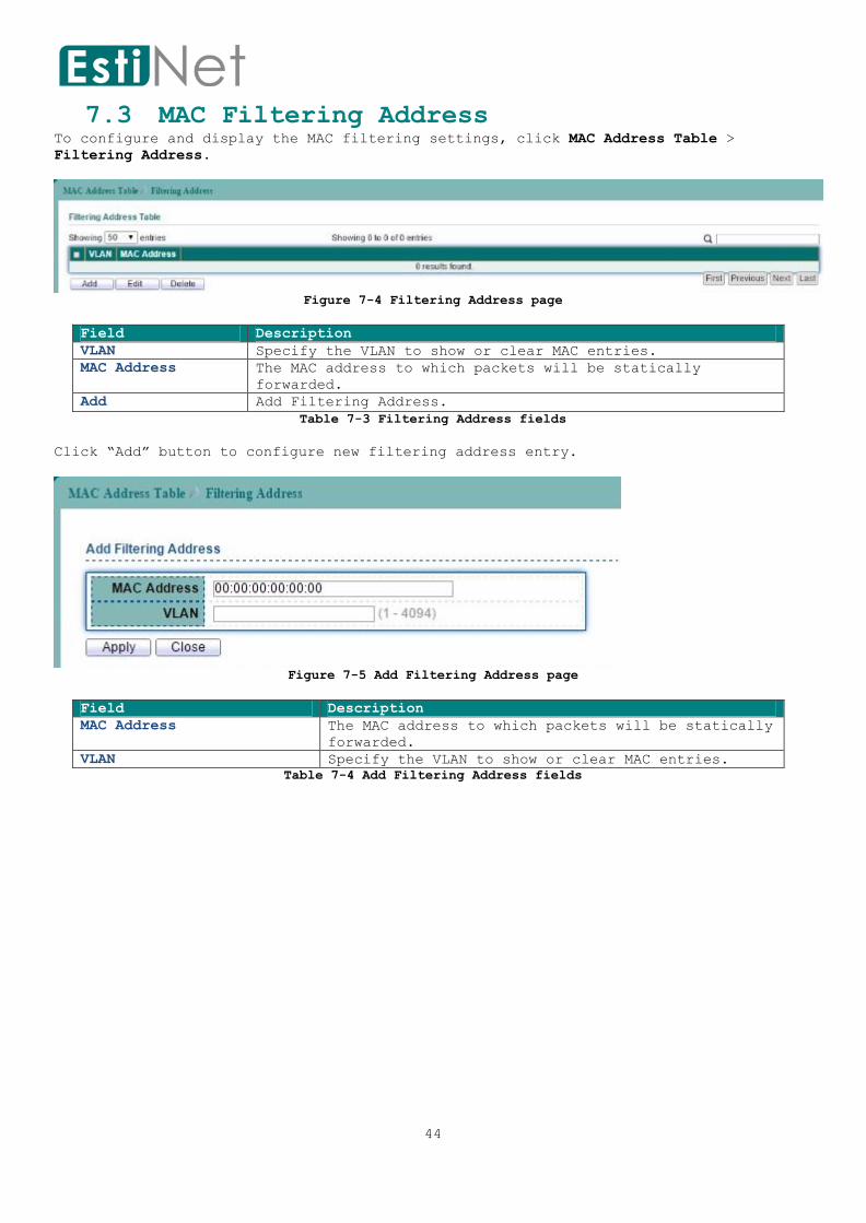
7.3 MAC Filtering Address To configure and display the MAC filtering settings, click MAC Address Table >
Filtering Address.
Figure 7-4 Filtering Address page
Field Description
VLAN Specify the VLAN to show or clear MAC entries.
MAC Address The MAC address to which packets will be statically
forwarded.
Add Add Filtering Address.
Table 7-3 Filtering Address fields
Click “Add” button to configure new filtering address entry.
Figure 7-5 Add Filtering Address page
Field Description
MAC Address The MAC address to which packets will be statically
forwarded.
VLAN Specify the VLAN to show or clear MAC entries.
Table 7-4 Add Filtering Address fields

45
8 Spanning Tree Protocol
The Spanning Tree Protocol (STP) is a network protocol that ensures a loop-free
topology for any bridged Ethernet local area network.
8.1 STP Property To configure and display STP configuration, click Spanning Tree > Property.
Figure 8-1 STP Property page
Field Description
State Enable/Disable the STP on the switch.
Operation Mode Specify the STP operation mode.
STP-Compatible: Enable the Spanning Tree (STP) operation.
RSTP-Operation: Enable the Rapid Spanning Tree (RSTP)
operation.
MSTP-Operation: Enable the Multiple Spanning Tree (MSTP)
operation.
Path Cost Specify the path cost method.
long: Flood the BPDU when STP is disabled.

46
short: Filter the BPDU when STP is disabled.
BPDU Handling Specify the BPDU forward method when the STP is disabled.
flooding: Flood the BPDU when STP is disabled.
filtering: Filter the BPDU when STP is disabled.
Priority Specify the CIST bridge priority. The valid range is from 0
to 61440. It ensures the probability that the switch is
selected as the root bridge, and the lower values has the
higher priority for the switch to be selected as the root
bridge of the STP topology.
Hello Time Specify the STP hello time in second to broadcast its hello
message to other bridges by Designated Ports. Its valid range
is from 1 to 10 seconds.
Max Age Specify the time interval in seconds for a switch to wait the
configuration messages, without attempting to redefine its
own configuration.
Forward Delay Specify the STP forward delay time, which is the amount of
time that a port remains in the Listening and Learning states
before it enters the Forwarding state. Its valid range is
from 4 to 10 seconds.
TX Hold Count Specify the tx-hold-count used to limit the maximum numbers
of packets transmission per second. The valid range is from 1
to 10.
Region Name The MSTP instance name. Its maximum length is 32 characters.
The default value is the MAC address of the switch.
Revision The MSTP revision number. Its valid rage is from 0 to 65535.
Max Hops Specify the number of hops in an MSTP region before the BPDU
is discarded. The valid range is 1 to 40.
Table 8-1 STP Property fields
47
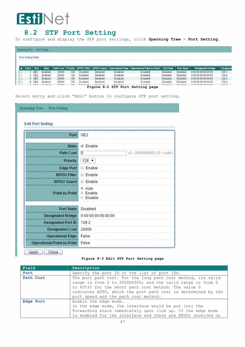
8.2 STP Port Setting To configure and display the STP port settings, click Spanning Tree > Port Setting.
Figure 8-2 STP Port Setting page
Select entry and click “Edit” button to configure STP port setting.
Figure 8-3 Edit STP Port Setting page
Field Description
Port Specify the port ID or the list of port IDs.
Path Cost The port path cost. For the long path cost method, its valid
range is from 0 to 200000000; and the valid range is from 0
to 65535 for the short path cost method. The value 0
indicates AUTO, which the port path cost is determined by the
port speed and the path cost method.
Edge Port Enable the edge mode.
In the edge mode, the interface would be put into the
Forwarding state immediately upon link up. If the edge mode
is enabled for the interface and there are BPDUs received on

48
the interface, the loop might be occurred in the short time.
Priority Specify the interface port priority of the CIST
BPDU Filter Enable the BPDU Filter configuration avoid
receiving/transmitting BPDU from the specified ports.
BPDU Guard Enable the BPDU Guard configuration to drop the received BPDU
directly.
Point-to-Point Specify the Point-to-Point port configuration.
Auto: Auto detect mode.
Enable: Enable Point-to-Point.
Disable: Disable Point-to-Point.
Table 8-2 STP Port Setting fields

49
8.3 MST Instance Setting
To configure and display the configuration for MST instance, click Spanning Tree > MST
Instance.
Figure 8-4 MST Instance page
Select MSTI entry and click “Edit” button to configure MST Instance entry.
Figure 8-5 Edit MST Instance Setting page
Field Description
MSTI ID Specify the MST instance ID.
VLAN List Specify the VLAN list to the specific instance.
Priority Specify the bridge priority on the specific instance. The
valid range is from 0 to 61440. It ensures the probability
that the switch is selected as the root bridge, and the lower
values has the higher priority for the switch to be selected
as the root bridge.
Table 8-3 MST Instance fields
50
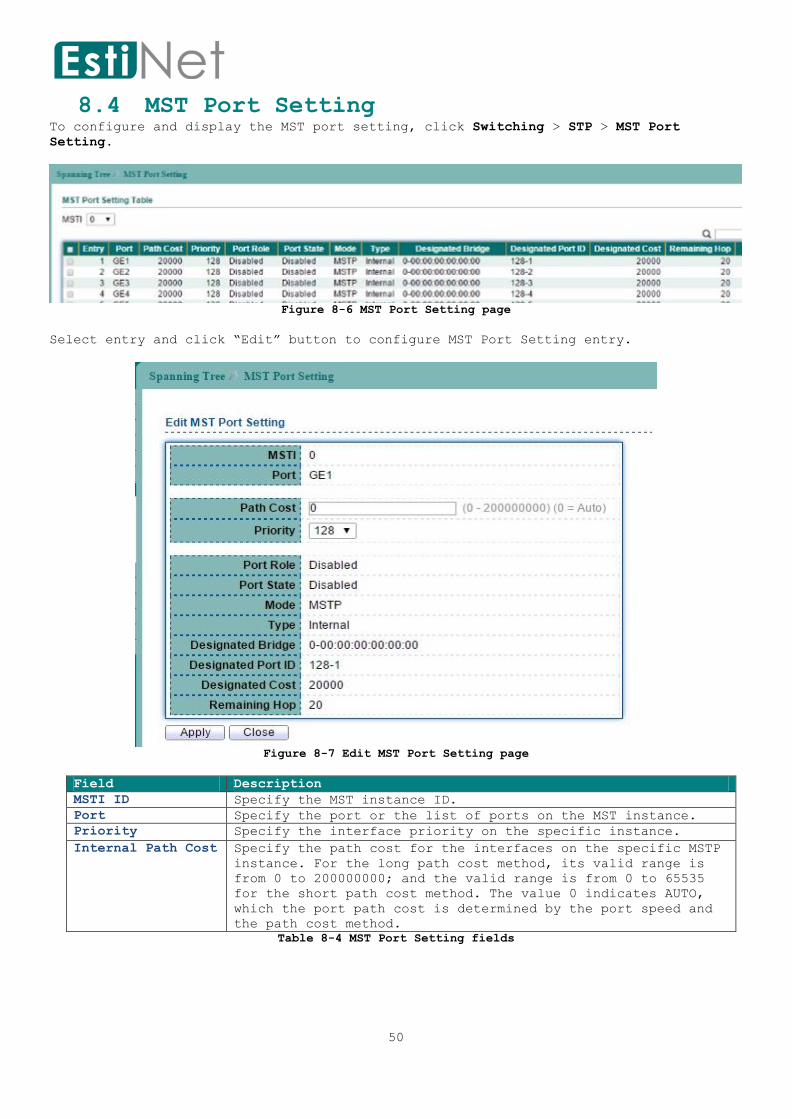
8.4 MST Port Setting To configure and display the MST port setting, click Switching > STP > MST Port
Setting.
Figure 8-6 MST Port Setting page
Select entry and click “Edit” button to configure MST Port Setting entry.
Figure 8-7 Edit MST Port Setting page
Field Description
MSTI ID Specify the MST instance ID.
Port Specify the port or the list of ports on the MST instance.
Priority Specify the interface priority on the specific instance.
Internal Path Cost Specify the path cost for the interfaces on the specific MSTP
instance. For the long path cost method, its valid range is
from 0 to 200000000; and the valid range is from 0 to 65535
for the short path cost method. The value 0 indicates AUTO,
which the port path cost is determined by the port speed and
the path cost method.
Table 8-4 MST Port Setting fields

51
8.5 STP Statistics To display the STP statistics, click Spanning Tree > STP Statistics.
Figure 8-8 STP Statistics page
Field Description
Port The switch port number.
Receive BPDU
Config The number of configuration BDPUs received.
TCN The number of TCN BDPUs received.
MSTP The number of Multiple Spanning Tree Protocol BDPUs received.
Transmit BPDU
Config The number of configuration BDPUs transmitted.
TCN The number of TCN BDPUs transmitted.
MSTP The number of Multiple Spanning Tree Protocol BDPUs
transmitted.
Table 8-5 STP Statistics fields
52
9 Discovery
LLDP is a one-way protocol; there are no request/response sequences. Information is
advertised by stations implementing the transmit function, and is received and
processed by stations implementing the receive function. The LLDP category contains
LLDP and LLDP-MED pages.
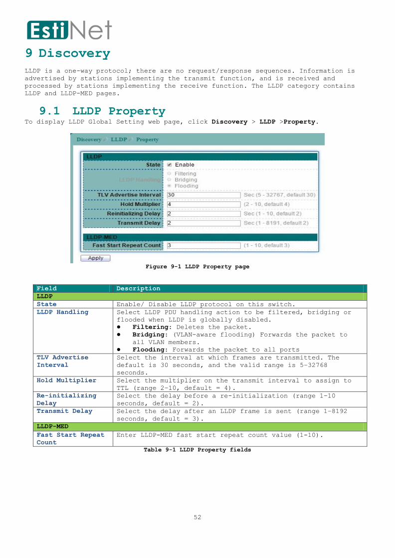
9.1 LLDP Property To display LLDP Global Setting web page, click Discovery > LLDP >Property.
Figure 9-1 LLDP Property page
Field Description
LLDP
State Enable/ Disable LLDP protocol on this switch.
LLDP Handling Select LLDP PDU handling action to be filtered, bridging or
flooded when LLDP is globally disabled.
Filtering: Deletes the packet.
Bridging: (VLAN-aware flooding) Forwards the packet to
all VLAN members.
Flooding: Forwards the packet to all ports
TLV Advertise
Interval
Select the interval at which frames are transmitted. The
default is 30 seconds, and the valid range is 5–32768
seconds.
Hold Multiplier Select the multiplier on the transmit interval to assign to
TTL (range 2–10, default = 4).
Re-initializing
Delay
Select the delay before a re-initialization (range 1–10
seconds, default = 2).
Transmit Delay Select the delay after an LLDP frame is sent (range 1–8192
seconds, default = 3).
LLDP-MED
Fast Start Repeat
Count
Enter LLDP-MED fast start repeat count value (1-10).
Table 9-1 LLDP Property fields

53
9.2 LLDP Port Setting
To display LLDP Port Setting, click Discovery > LLDP > Port Setting.
Figure 9-2 LLDP Port Setting page
Select entry and click “Edit” button to configure LLDP Port Setting entry.
Figure 9-3 Edit LLDP Port Setting page
Field Description
Port Selected port(s).
Mode Select the transmission state of LLDP port interface.
Transmit: Transmit LLDP PDUs only.
Receive: Receive LLDP PDUs only.
Normal: Transmit and receive LLDP PDUs both.
Disable: Disable the transmission of LLDP PDUs.
Optional TLV
Select
Select the LLDP optional TLVs to be carried (multiple selection
is allowed).

54
System Name
Port Description
System Description
System Capability
802.3 MAC-PHY
802.3 Link Aggregation
802.3 Maximum Frame Size
Management Address
802.1 PVID
802.1 VLAN Name Select the VLAN Name ID to be carried (multiple selection is
allowed).
Table 9-2 LLDP Port Setting fields

55
9.3 LLDP MED Network Policy Setting
To display LLDP MED Network Policy Setting, click Discovery> LLDP > MED Network
Policy.
Figure 9-4 LLDP MED Network Policy page
Click “Add” button to configure new LLDP MED Network Policy entry.
Figure 9-5 Add LLDP MED Network Policy page
Field Description
Policy ID Select specified network policy ID to configure.
Application Select the network policy application type.
Voice
Voice Signaling
Guest Voice
Guest Voice Signaling
Softphone Voice
Video Conferencing
App Streaming Video
Video Signaling
VLAN Set the VLAN ID, range from 1 to 4094.
VLAN Tag Set the VLAN tag status.
Tagged: Traffic is tagged.
Untagged: Traffic is untagged.
Priority Set the L2 priority, range from 0 to 7.
DSCP Set the DSCP value, range from 0 to 63
Table 9-3 LLDP MED Network Policy fields

56
9.4 LLDP MED Port Setting To display LLDP MED Port Setting, click Discovery > LLDP > MED Port Setting.
Figure 9-6 LLDP MED Port Setting page
Select entry and click “Edit” button to configure LLDP MED Port Setting entry.
Figure 9-7 Edit LLDP MED Port Setting page
Field Description
Port Select specified port or all ports to configure LLDP
MED.
State Select LLDP MED enable status.
Optional TLVs Select LLDP MED optional TLVs (multiple selection is
allowed)
Network Policy
Location
Inventory
Network Policy Select the network policy IDs to be bound to ports. The
network policy should be created in MED Network Policy
page at first.
Table 9-4 LLDP MED Port Setting fields

57
9.5 LLDP Local Information
To display LLDP Local Device Information, click Discovery > LLDP > Local Information.
Click “Detail” button on the page to view detail information of the selected port.
Figure 9-8 LLDP Local Information page

58
Figure 9-9 LLDP Local Information Detail page
Field Description
Chassis ID Subtype Type of chassis ID, such as the MAC address.
Chassis ID Identifier of chassis. Where the chassis ID subtype is a MAC

59
address, the MAC address of the switch is displayed.
System Name Name of switch.
System Description Description of the switch.
Supported
Capabilities
Primary functions of the device, such as Bridge, WLAN AP, or
Router.
Enabled
Capabilities
Primary enabled functions of the device.
Port ID Subtype Type of the port identifier that is shown.
LLDP State LLDP Tx and Rx abilities.
LLDP Med State LLDP MED enable state.
Table 9-5 LLDP Local Information fields

60
9.6 LLDP Neighbor To display LLDP Neighbor Devices, click Discovery > LLDP > Neighbor.
Click “Detail” to view selected neighbor detail information.
Figure 9-10 LLDP Neighbor page
Field Description
Local Port Number of the local port to which the neighbor is
connected.
Chassis ID
Subtype
Type of chassis ID (for example, MAC address).
Chassis ID Identifier of the 802 LAN neighboring device's chassis.
Port ID Subtype Type of the port identifier that is shown.
Port ID Identifier of port.
System Name Published name of the switch.
Time to Live Time interval in seconds after which the information for
this neighbor is deleted.
Table 9-6 LLDP Neighbor fields

61
9.7 LLDP Statistics To display LLDP Statistics, click Discovery > LLDP > Statistics.
Figure 9-11 LLDP Statistics page
Field Description
Port Port Name.
Total Total number of bytes of LLDP information in each packet.
Left to Send Total number of available bytes left for additional LLDP
information in each packet.
Status Overloading or not.
Mandatory TLVs Total mandatory TLV byte size. Status is sent or overloading.
MED Capabilities Total MED Capabilities TLV byte size. Status is sent or
overloading.
MED Location Total MED Location byte size.
Status is sent or overloading.
MED Network Policy Total MED Network Policy byte size. Status is sent or
overloading.
MED Extended Power
via MDI
Total MED Extended Power via MDI byte size. Status is sent or
overloading.
802.3 TLVs Total 802.3 TLVs byte size. Status is sent or overloading.
Optional TLV Total Optional TLV byte size.
Status is sent or overloading.
MED Inventory Total MED Inventory byte size. Status is sent or overloading.
802.1 TLVs Total 802.1 TLVs byte size.
Status is sent or overloading.
Table 9-7 LLDP Statistics fields

62
10 Multicast
10.1 General
10.1.1 Multicast Property To display Multicast Property Setting web page, click Multicast > General > Property.
This page allow user to set multicast forwarding method and unknown multicast action.
Figure 10-1 Multicast Property page
Field Description
Unknown Multicast Action Set the unknown multicast action
Flood: flood the unknown multicast data.
Drop: drop the unknown multicast data.
Forward Router port: forward the unknown
multicast data to router port.
Multicast Forward Method
IPv4 Set the ipv4 multicast forward method.
DMA-VID (MAC): forward method dmac+vid.
DIP-VID (Src-Dst-Ip): forward method dip+sip.
IPv6 Set the ipv6 multicast forward method.
DMA-VID (MAC): forward method dmac+vid.
DIP-VID (Src-Dst-Ip): forward method
dip+sip(dip low 32 bit, sip low 24bit +
40~47bit).
Table 10-1 Multicast Property fields

63
10.1.2 Multicast Group Address To display Multicast Group Address web page, click Multicast > General > Group
Address.
This page allow user to browse all IGMP snooping groups that dynamic learned or
statically added. Also allows user to add, edit or delete static group for IGMP
snooping.
Figure 10-2 Multicast Group Address page
Field Description
VLAN ID The VLAN ID of this group.
Group Address The group IP address of this group.
Member The member ports of this group.
Type The type of this group. Static or Dynamic.
Life(Sec) The life time of this group.
Table 10-2 Multicast Group Address fields
Click “Add” button to add a static multicast group.
Figure 10-3 Add Multicast Group Address page
Field Description
VLAN Select the VLANs ID to configure.
IP Version Group IP Address of IPv4 or IPv6.
Group Address The multicast IP address of this group.
Member The member ports of this group.
Table 10-3 Add Multicast Group Address fields

64
10.1.3 Multicast Router Port To display Multicast Router Setting web page, click Multicast > General > Router Port.
This page allow user to browse all router information of IGMP Snooping. And also
allows user to add, edit or delete static and forbidden router port on specific VLANs.
Figure 10-4 Multicast Router Port page
Field Description
VLAN The VLAN that router port belong to.
Member The member ports.
Static Port Static Port: All packets that need sent to router will forward
to this port.
Forbidden Port Forbidden Port: All packets that need sent to router will NOT
forward to this port.
Life (Sec) The expiry time of the router port.
Table 10-4 Multicast Router Port fields
Click “Add” button to configure new Multicast Router Port entry.

65
Figure 10-5 Add Multicast Router Port page
Field Description
VLAN The VLAN ID for router setting.
IP Version IP version: IPv4 or IPv6
Type The router port type
Static: All packets that need sent to router will
forward to this port.
Forbidden: All packets that need sent to router will NOT
forward to this port.
Port The member ports.
Table 10-5 Add Multicast Router Port fields

66
10.1.4 Multicast Forward All To display IGMP Forward All web page, click Multicast > General > Forward All.
This page allow user to configure all port forwarding status on specified VLAN of IGMP
Snooping.
Figure 10-6 Multicast Forward All page
Field Description
VLAN The VLAN Create by user.
Static Port All packets that on specified VLAN will forward to this
port.
Forbidden Port All packets that on specified VLAN will NOT forward to this
port.
Table 10-6 Multicast Forward All Fields
Click “Add” button to create a new Forward All entry.
67
Figure 10-7 Add Multicast Forward All page
Field Description
VLAN The VLAN Create by user.
IP Version IP version: IPv4 or IPv6
Type The router port type
Static: all packets that need sent to router will forward
to this port.
Forbidden: all packets that need sent to router will NOT
forward to this port.
Port Port or Ports that will be added to the forward all session.
Table 10-7 Add Multicast Forward All fields

68
10.1.5 Multicast Throttling
To display multicast max-groups number and action setting web page, click Multicast >
General > Throttling.
This page allow user to configure all port forwarding status on specified VLAN of IGMP
Snooping.
Figure 10-8 Multicast Throttling page
Select entry and click “Edit” button to configure Multicast Throttling entry.
Figure 10-9 Edit Multicast Throttling page
Field Description
Port Selected port or ports.
IP Type Ipv4 for IGMP snooping max groups setting.
Max Groups Max number of group for port.
Exceed Action Excess Max number of group action.
Deny: do not learning group.
Replace: random replace one exist group.
Table 10-8 Edit Multicast Throttling fields
69
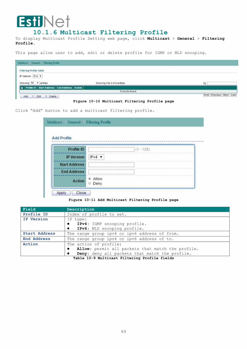
10.1.6 Multicast Filtering Profile To display Multicast Profile Setting web page, click Multicast > General > Filtering
Profile.
This page allow user to add, edit or delete profile for IGMP or MLD snooping.
Figure 10-10 Multicast Filtering Profile page
Click “Add” button to add a multicast filtering profile.
Figure 10-11 Add Multicast Filtering Profile page
Field Description
Profile ID Index of profile to set.
IP Version IP type:
IPv4: IGMP snooping profile.
IPv6: MLD snooping profile.
Start Address The range group ipv4 or ipv6 address of from.
End Address The range group ipv4 or ipv6 address of to.
Action The action of profile:
Allow: permit all packets that match the profile.
Deny: deny all packets that match the profile.
Table 10-9 Multicast Filtering Profile fields

70
10.1.7 Multicast Filtering Binding To display Multicast Filtering Binding Setting web page, click Multicast > General >
Filtering Binding > IGMP Filter Setting.
This page allow user to bind/remove profile to/from each port of IGMP snooping.
Figure 10-12 Multicast Filtering Binding page
Select entry and click “Edit” button to configure Multicast Filtering Binding entry.
Figure 10-13 Edit Multicast Filtering Binding page
Field Description
Port Selected ports to configure
IP Version IP type:
IPv4: IGMP snooping profile.
IPv6: MLD snooping profile.
Filter profile ID Profile index.
Table 10-10 Multicast Filter Binding fields

71
10.2 IGMP Snooping
10.2.1 IGMP Property To display IGMPVLAN Setting webpage, click Multicast > IGMP Snooping > Property.
This page allow user to configure global settings of IGMP snooping and configure
specific VLAN settings of IGMP Snooping.
Figure 10-14 IGMP Snooping Property page
Field Description
State Set the enabling status of IGMP functionality
Enable: Enable IGMP Snooping.
Version Set the IGMP snooping version
v2: Only support process IGMP v2 packet.
v3: Support v3 basic and v2.
Report Suppression Set the enabling status of IGMP v2 report suppression
Enable: Enable IGMP Snooping v2 report
suppression.
Disable: Disable IGMP Snooping v2 report
suppression.
VLAN Setting Table
Entry No The IGMP entry number.
VLAN The IGMP entry VLAN ID
Operation Status The enable status of IGMP VLAN functionality.
Enabled: when IGMP Snooping enable and IGMP VLAN
enable and multicast filtering enable.
Disabled: when IGMP Snooping disable or IGMP VLAN
disable or multicast filtering disable.
Router Ports Auto Learn Set the enabling status of IGMP router port learning
Enabled: Enable learning router port by query and
PIM, DVRMP.
Disabled: Disable learning dynamic router port.
Query Robustness The Query Robustness allows tuning for the expected
packet loss on a subnet.
Query Interval The interval of querier to send general query
Query Max Response
Interval
In Membership Query Messages, it specifies the maximum
allowed time before sending a responding report in
units of 1/10 second.
Last Member Query Counter The count that Querier-switch sends Group-Specific
Queries when it receives a Leave Group message for a
group.

72
Last Member Query Interval The interval that Querier-switch sends Group-Specific
Queries when it receives a Leave Group message for a
group.
Immediate leave Leave the group when receive IGMP Leave message.
Enabled: Enable Fastleave.
Disabled: Disable Fastleave.
Table 10-11 IGMP Snooping Property fields
Select entry and click “Edit” button to configure IGMP Snooping VLAN Setting entry.
Figure 10-15 Edit IGMP Snooping Property page
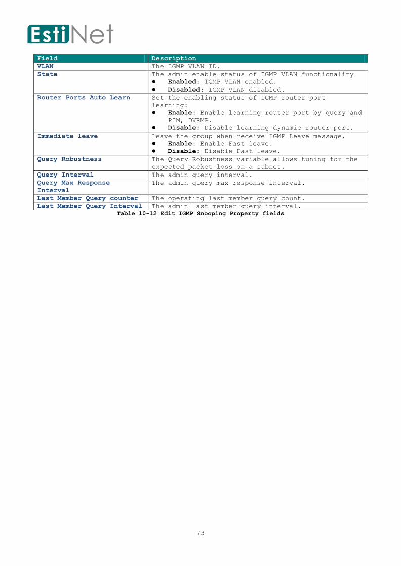
73
Field Description
VLAN The IGMP VLAN ID.
State The admin enable status of IGMP VLAN functionality
Enabled: IGMP VLAN enabled.
Disabled: IGMP VLAN disabled.
Router Ports Auto Learn Set the enabling status of IGMP router port
learning:
Enable: Enable learning router port by query and
PIM, DVRMP.
Disable: Disable learning dynamic router port.
Immediate leave Leave the group when receive IGMP Leave message.
Enable: Enable Fast leave.
Disable: Disable Fast leave.
Query Robustness The Query Robustness variable allows tuning for the
expected packet loss on a subnet.
Query Interval The admin query interval.
Query Max Response
Interval
The admin query max response interval.
Last Member Query counter The operating last member query count.
Last Member Query Interval The admin last member query interval.
Table 10-12 Edit IGMP Snooping Property fields

74
10.2.2 IGMP Querier Setting
To display IGMP Querier Setting web page, click Multicast> IGMP Snooping > Querier.
This page allow user to configure querier settings on specific VLAN of IGMP Snooping.
Figure 10-16 IGMP Snooping Querier page
Select entry and click “Edit” button to configure IGMP Snooping Querier entry.
Figure 10-17 Edit IGMP Snooping Querier page
Field Description
VLAN Select the VLANs to configure.
State Set the enabling status of IGMP Querier Election on the chose
VLANs.
Enabled: Enable IGMP Querier.
Disabled: Disable IGMP Querier.
Operation Status The enable status of IGMP VLAN functionality.
Enabled: when IGMP Snooping enable and IGMP VLAN enable
and multicast filtering enable.
Disabled: when IGMP Snooping disable or IGMP VLAN disable
or multicast filtering disable.
Querier Version Set the query version of IGMP Querier Election on the chose
VLANs.
v2: Querier version 2.
v3: Querier version 3.
Querier Address The real Querier IP address on the VLAN.
Table 10-13 IGMP Snooping Querier fields

75
10.3 MLD Snooping 10.3.1 MLD Snooping Property
To display MLDVLAN Setting webpage, click Multicast > MLD Snooping > Property.
This page allow user to configure global settings of IGMP snooping and configure
specific VLAN settings of IGMP Snooping.
Figure 10-18 MLD Snooping Property page
Field Description
MLD Snooping
State
Set the enabling status of ,MLD functionality
Enable: Enable MLD Snooping.
Disable: Disable MLD Snooping.
Version Set the MLD snooping version
v1: Only support process MLD v1 packet.
v2: Support v2 basic and v1.
Snooping Report
Suppression
Set the enabling status of MLD v2 report suppression
Enable: Enable MLD Snooping v1 report suppression.
Disable: Disable MLD Snooping v1 report suppression.
VLAN Setting Table
Entry No The MLD entry number.
VLAN The MLD entry VLAN ID.
Operation Status The enable status of MLD VLAN functionality
Enabled: when MLD Snooping enable and MLD VLAN enable and
multicast filtering enable.
Disabled: when MLD Snooping disable or MLD VLAN disable.
Router Ports Auto
Learn
Set the enabling status of MLD router port learning
Enabled: Enable learning router port by query and PIM,
DVRMP.
Disabled: Disable learning dynamic router port.
Query Robustness The Query Robustness allows tuning for the expected packet loss
on a subnet.
Query Interval The interval of querier send general query
Query Max
Response Interval
In Membership Query Messages, it specifies the maximum allowed
time before sending a responding report in units of 1/10
second.
Last Member Query
Counter
The count that Querier-switch sends Group-Specific Queries when
it receives a Leave Group message for a group.
Last Member Query
Interval
The interval that Querier-switch sends Group-Specific Queries
when it receives a Leave Group message for a group.
Immediate leave Leave the group when receive MLD Leave message.
Enabled: Enable Fastleave.
Disabled: Disable Fastleave.
Table 10-14 MLD Snooping Property fields

76
Select entry and click “Edit” button to configure MLD Snooping VLAN Setting entry.
Figure 10-19 Edit MLD Snooping Property page
Table 10-15 Edit MLD Snooping Property fields
Field Description
VLAN The MLD VLAN ID
State The admin enable status of MLD VLAN functionality
Enabled: MLD VLAN enable.
Disabled: MLD VLAN disable.
Router Ports Auto
Learn
Set the enabling status of MLD router port learning
Enabled: Enable learning router port by query and PIM,
DVRMP.
Disabled: Disable learning dynamic router port.
Immediate leave Leave the group when receive MLD Leave message.
Enabled: Enable Fast leave.
Disabled: Disable Fast leave.
Query Robustness The Query Robustness allows tuning for the expected packet loss
on a subnet.
Query Interval The query interval.
Query Max
Response Interval
The query max response interval.
Last Member Query
Counter
The last member query count.
Last Member Query
Interval
The last member query interval.

77
10.3.2 MLD Snooping Statistics To display MLD Snooping Statistic web page, click Multicast > MLD Snooping >
Statistics.
Figure 10-20 MLD Snooping Statistics page

78
10.4 MVR Multicast VLAN registration (MVR) allows a single multicast VLAN to be shared in the
network while other subscribers remain in the different VLANS. MVR reduce the amount
of bandwidth consumed by the same multicast traffic and makes multicast service become
more efficiency.
10.4.1 MVR Property To display MVR Setting web page, click Multicast > MVR > Property.
This page allow user to configure MVR global function.
Figure 10-21 MVR Property page
Field Description
State To enable MVR on the switch.
VLAN Select a VLAN in which multicast data is received; all source
ports needs belong to this VLAN.
Mode
Group Group start address.
Group Count Specifies the maximum number of MVR groups.
Query Time Query response time
Table 10-16 MVR Property fields

79
10.4.2 MVR Port Setting To display MVR Port Setting web page, click Multicast > MVR > Port Setting.
Figure 10-22 MVR Port Setting page
Select entry and click “Edit” button to configure MVR port setting entry.
Figure 10-23 Edit MVR Port Setting page
Field Description
Port Selected port.
Role Select a Role for this port.
None: MVR disabled on this port.
Receiver: The subscriber port, it only receive multicast
data.
Source: The port that receives and send multicast data.
Immediate Leave Enable immediate leave feature of MVR on the port. Immediate
Leave should only apply to the Receiver port.
Table 10-17 MVR Port Setting fields
80
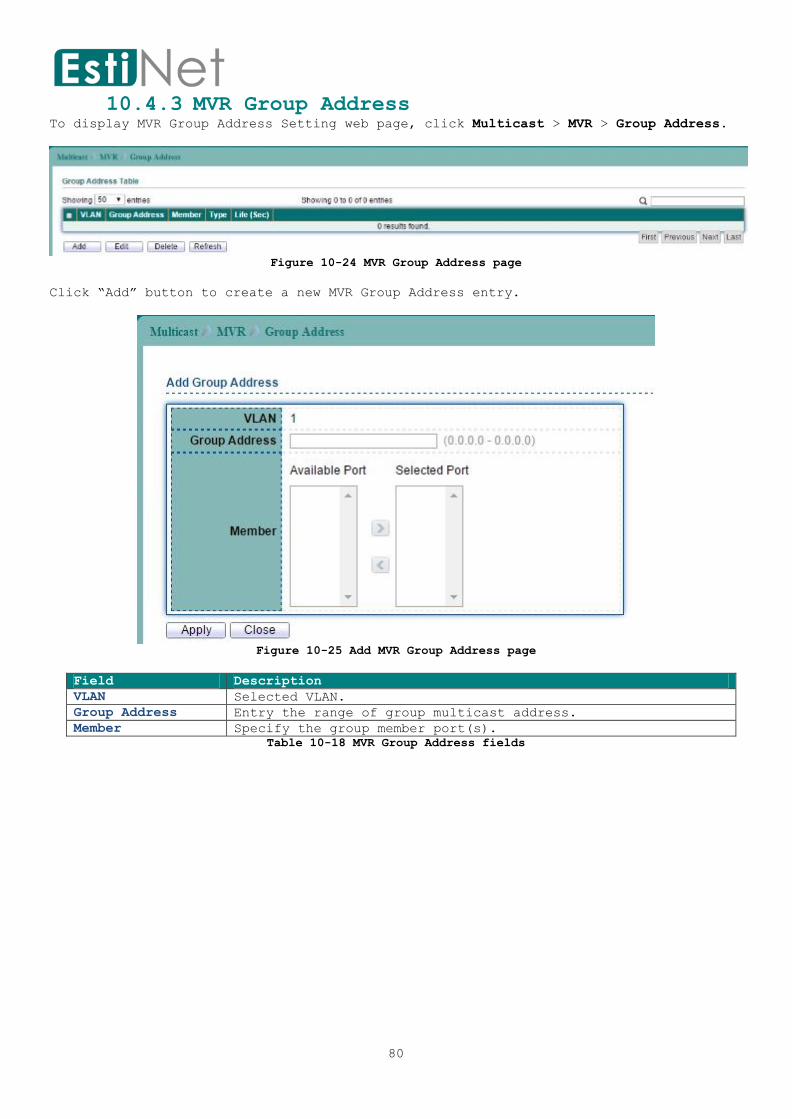
10.4.3 MVR Group Address To display MVR Group Address Setting web page, click Multicast > MVR > Group Address.
Figure 10-24 MVR Group Address page
Click “Add” button to create a new MVR Group Address entry.
Figure 10-25 Add MVR Group Address page
Field Description
VLAN Selected VLAN.
Group Address Entry the range of group multicast address.
Member Specify the group member port(s).
Table 10-18 MVR Group Address fields

81
11 Security
Use the Security pages to configure settings for the switch security features.
11.1 RADIUS Server To display RADIUS Server web page, click Security > RADIUS Server.
This page allow user to add, edit or delete RADIUS server settings and modify default
parameter of RADIUS server.
Figure 11-1 RADIUS Server page
Field Description
Retry RADIUS server default retry times.
Timeout RADIUS server default timeout value.
Key String RADIUS server default key string.
Table 11-1 RADIUS Server fields
Click “Add” button to create a new RADIUS server entry.
Figure 11-2 Add RADIUS Server page

82
Field Description
Address Type Server Address Type:
Host name: Use host name as server address.
IPv4 address: Use IPv4 address as server address.
IPv6 address: Use IPv6 address as server address.
Server Address RADIUS server IP address.
Server Port RADIUS server UDP port for Authentication.
Priority RADIUS server priority (smaller value has higher priority).
RADIUS session will try to establish with the server setting
which has highest priority. If failed, it will try to connect
to the server with next higher priority.
Key String RADIUS server key string.
Timeout for Reply RADIUS server timeout value. If it is fail to connect to
server, it will keep trying until timeout.
Retry RADIUS server retry value. If it is fail to connect to
server, it will keep trying until timeout with retry times.
Timeout RADIUS server dead time of session.
Usage RADIUS server usage type
Login: For login authentication
802.1x: For 802.1x authentication
All: For all types
Table 11-2 Add RADIUS Server fields
83
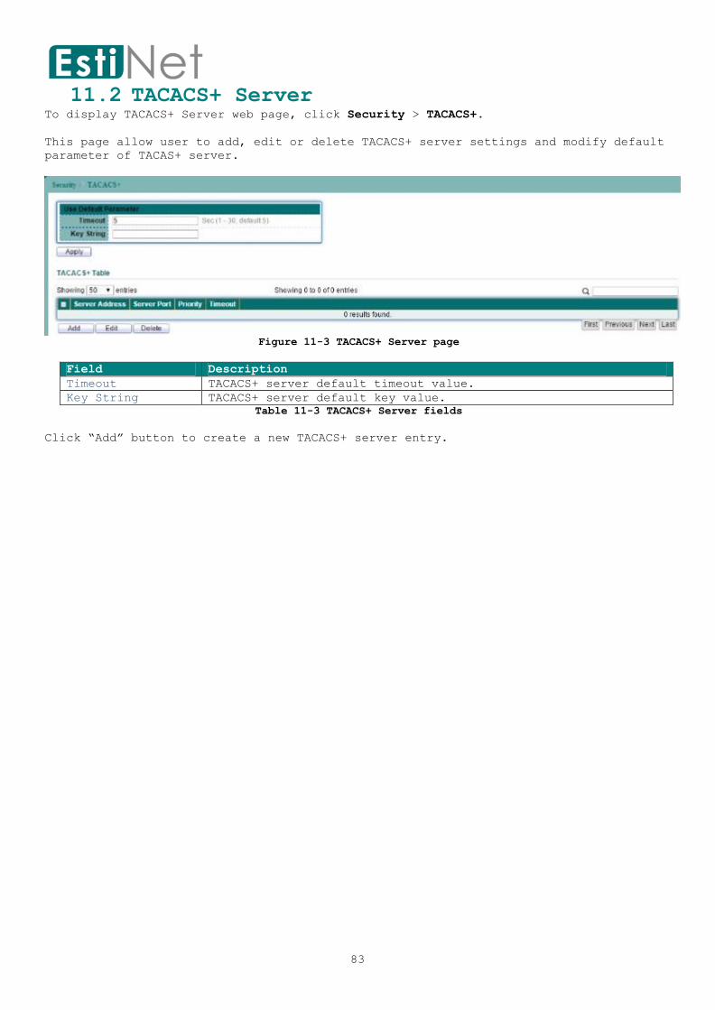
11.2 TACACS+ Server To display TACACS+ Server web page, click Security > TACACS+.
This page allow user to add, edit or delete TACACS+ server settings and modify default
parameter of TACAS+ server.
Figure 11-3 TACACS+ Server page
Field Description
Timeout TACACS+ server default timeout value.
Key String TACACS+ server default key value.
Table 11-3 TACACS+ Server fields
Click “Add” button to create a new TACACS+ server entry.

84
Figure 11-4 Add TACACS+ Server page
Field Description
Address Type Server Address Type
Host name: Use host name as server address.
IPv4 address: Use IPv4 address as server address.
IPv6 address: Use IPv6 address as server address.
Server Address TACACS+ server IP address.
Server Port TACACS+ server UDP port.
Priority TACACS+ server priority (smaller value has higher priority).
TACACS+ session will try to establish with the server setting
which has highest priority. If failed, it will try to connect
to the server with next higher priority.
Key String TACACS+ server key value or use default parameter.
Timeout TACACS+ server timeout value. If it is fail to connect to
server, it will keep trying until timeout. Or use default
parameter.
Table 11-4 Add TACACS+ Server fields

85
11.3 AAA
11.3.1 AAA Method List To display Login List web page, click Security > AAA > Method List.
This page allow user to add, edit or delete login authentication list settings (The
“default” list cannot be deleted.). The line combined to this list will authenticate
login user by methods in this list. If the first method is failed, it will try to use
the next priority method to authenticate if it exists.
With RADIUS and TACACS+ methods, the failed means connecting to server fail. With Local
method, the failed means cannot find the user in local database.
Figure 11-5 AAA Method List page
Click “Add” button to create a new AAA Method List entry.
Figure 11-6 Add AAA Method List page
Field Description
Name New login authentication list name. This name should
be different from other existing lists.
Method 1 Select first priority of login authentication method.

86
Empty: Function disabled.
None: Authenticated with any condition.
Local: Use local accounts database to authenticate
Enable: Use local enable password to authenticate.
Radius: Use remote Radius server to authenticate.
TACACS+: Use remote TACACS+ server to
authenticate.
Method 2 Select first priority of login authentication method.
Empty: Function disabled.
None: Authenticated with any condition.
Local: Use local accounts database to authenticate
Enable: Use local enable password to authenticate.
Radius: Use remote Radius server to authenticate.
TACACS+: Use remote TACACS+ server to authenticate
Method 3 Select first priority of login authentication method.
Empty: Function disabled.
None: Authenticated with any condition.
Local: Use local accounts database to authenticate
Enable: Use local enable password to authenticate.
Radius: Use remote Radius server to authenticate.
TACACS+: Use remote TACACS+ server to authenticate
Method 4 Select first priority of login authentication method.
Empty: Function disabled.
None: Authenticated with any condition.
Local: Use local accounts database to authenticate
Enable: Use local enable password to authenticate.
Radius: Use remote Radius server to authenticate.
TACACS+: Use remote TACACS+ server to authenticate
Table 11-5 Add AAA Method List fields

87
11.3.2 AAA Login Authentication. To display AAA Login Authentication web page, click Security > AAA > Login
Authentication.
This page also allow user to select one of AAA Method lists to Console, Telnet, SSH,
HTTP and HTTPS connections. The user accesses switch from those connections will be
authenticated by AAA Method lists we created from "Method List" page.
Figure 11-7 AAA Login Authentication page
Field Description
Console Login Authentication for Console connection.
Telnet Login Authentication for Telnet connection.
SSH Login Authentication for SSH connection.
HTTP Login Authentication for HTTP connection.
HTTPS Login Authentication for HTTPS connection.
Table 11-6 AAA Login Authentication fields

88
11.4 Management Access
11.4.1 Management VLAN To display Management VLAN web page, click Security > Management Access > Management
VLAN.
This page allow user to change management VLAN.
Figure 11-8 Management VLAN page
Field Description
Management VLAN Management connection, such as http, https, snmp etc.., has
the same VLAN of management VLAN are allow connecting to
device. Others will be dropped.
Table 11-7 Management VLAN fields

89
11.4.2 Management Service To display Management Service web page, click Security > Management Access > Management
Service.
This page allow user to configure Management Service setting.
Figure 11-9 Management Service page
Field Description
Management Service
Telnet Support Telnet Connection
Enable: Enable Telnet service.
SSH Support SSH Connection
Enable: Enable SSH service.
HTTP Support HTTP Connection
Enable: Enable HTTP service.
HTTPS Support HTTPS Connection
Enable: Enable HTTPS service.
SNMP Support SNMP Connection
Enable: Enable SNMP service.
Session Timeout
Console Set session timeout minutes for user access CLI from
console line. If user does not response after session

90
timeout minute, CLI will logout automatically. 0 minutes
means never timeout.
Telnet Set session timeout minutes for user access CLI from Telnet
connection. If user does not response after session timeout
minute, CLI will logout automatically. 0 minutes means
never timeout.
SSH Set session timeout minutes for user access CLI from SSH
connection. If user does not response after session timeout
minute, CLI will logout automatically. 0 minutes means
never timeout.
HTTP Set session timeout minutes for user access CLI from HTTP
connection. If user does not response after session timeout
minute, WEBUI will logout automatically. 0 minutes means
never timeout.
HTTPS Set session timeout minutes for user access CLI from HTTPS
connection. If user does not response after session timeout
minute, WEBUI will logout automatically. 0 minutes means
never timeout.
Password Retry Count
Console Set session timeout minutes for user access CLI from
console line. If user does not response after session
timeout minute, CLI will logout automatically. 0 minutes
means never timeout.
Telnet Set session timeout minutes for user access CLI from Telnet
connection. If user does not response after session timeout
minute, CLI will logout automatically. 0 minutes means
never timeout.
SSH Set session timeout minutes for user access CLI from SSH
connection. If user does not response after session timeout
minute, CLI will logout automatically. 0 minutes means
never timeout.
Silent Time
Console After input error password exceeds password retry count,
the CLI will freeze after silent time.
Telnet After input error password exceeds password retry count,
the Telnet will freeze after silent time.
SSH After input error password exceeds password retry count,
the SSH will freeze after silent time.
Table 11-8 Management Service fields

91
11.4.3 Management ACL To display Management ACL web page, click Security > Management Access > Management
ACL.
This page allow user to create, active or deactivate Management ACL profile. Only one
profile can be active in device. All packets will be dropped if match deny rule or not
match any permit rule.
Figure 11-10 Management ACL page
Field Description
ACL Name Input profile name. If the name is not existed, a new profile
will be created. Or the rule will append to exist profile.
Table 11-9 Management ACL fields
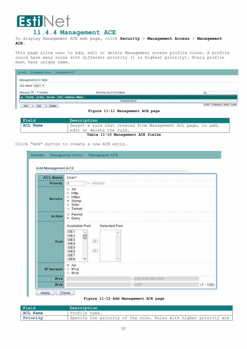
92
11.4.4 Management ACE To display Management ACE web page, click Security > Management Access > Management
ACE.
This page allow user to add, edit or delete Management access profile rules. A profile
could have many rules with different priority (1 is highest priority). Every profile
must have unique name.
Figure 11-11 Management ACE page
Field Description
ACL Name Select a rule that created from Management ACL page, to add,
edit or delete the rule.
Table 11-10 Management ACE fields
Click “Add” button to create a new ACE entry.
Figure 11-12 Add Management ACE page
Field Description
ACL Name Profile name.
Priority Specify the priority of the rule. Rules with higher priority are
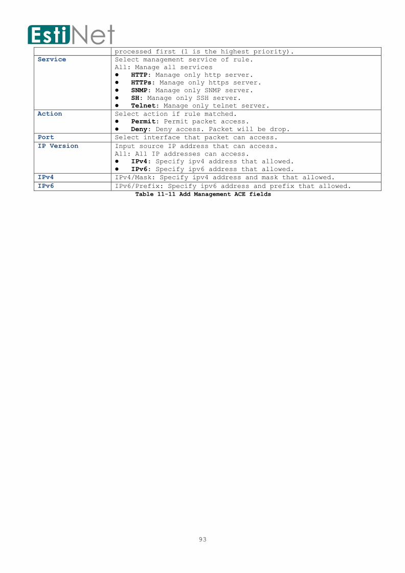
93
processed first (1 is the highest priority).
Service Select management service of rule.
All: Manage all services
HTTP: Manage only http server.
HTTPs: Manage only https server.
SNMP: Manage only SNMP server.
SH: Manage only SSH server.
Telnet: Manage only telnet server.
Action Select action if rule matched.
Permit: Permit packet access.
Deny: Deny access. Packet will be drop.
Port Select interface that packet can access.
IP Version Input source IP address that can access.
All: All IP addresses can access.
IPv4: Specify ipv4 address that allowed.
IPv6: Specify ipv6 address that allowed.
IPv4 IPv4/Mask: Specify ipv4 address and mask that allowed.
IPv6 IPv6/Prefix: Specify ipv6 address and prefix that allowed.
Table 11-11 Add Management ACE fields

94
11.5 Authentication Manager
11.5.1 Authentication Manager Property To display Authentication Manager Property Setting web page, click Security >
Authentication Manager > Property.
Figure 11-13 Authentication Manager Property page
Select entry and click “Edit” button to configure Authentication Manager Port Mode
entry.

95
Figure 11-14 Edit Authentication Manager Property page
Field Description
Port Port Number
Authentication
Type
The authentication type will be used.
Host Mode The mode to decide how many hosts should pass authentication.
Order Specify the order of authentication type. Authentication type
with higher priority are processed first (1 is the highest
priority).
Method The authentication method.
Guest VLAN To enable guest VLAN for the hosts that authentication fail.
VLAN Assign Mode Specify the VLAN assign mode after finish authentication.
Table 11-12 Edit Authentication Manager Property fields
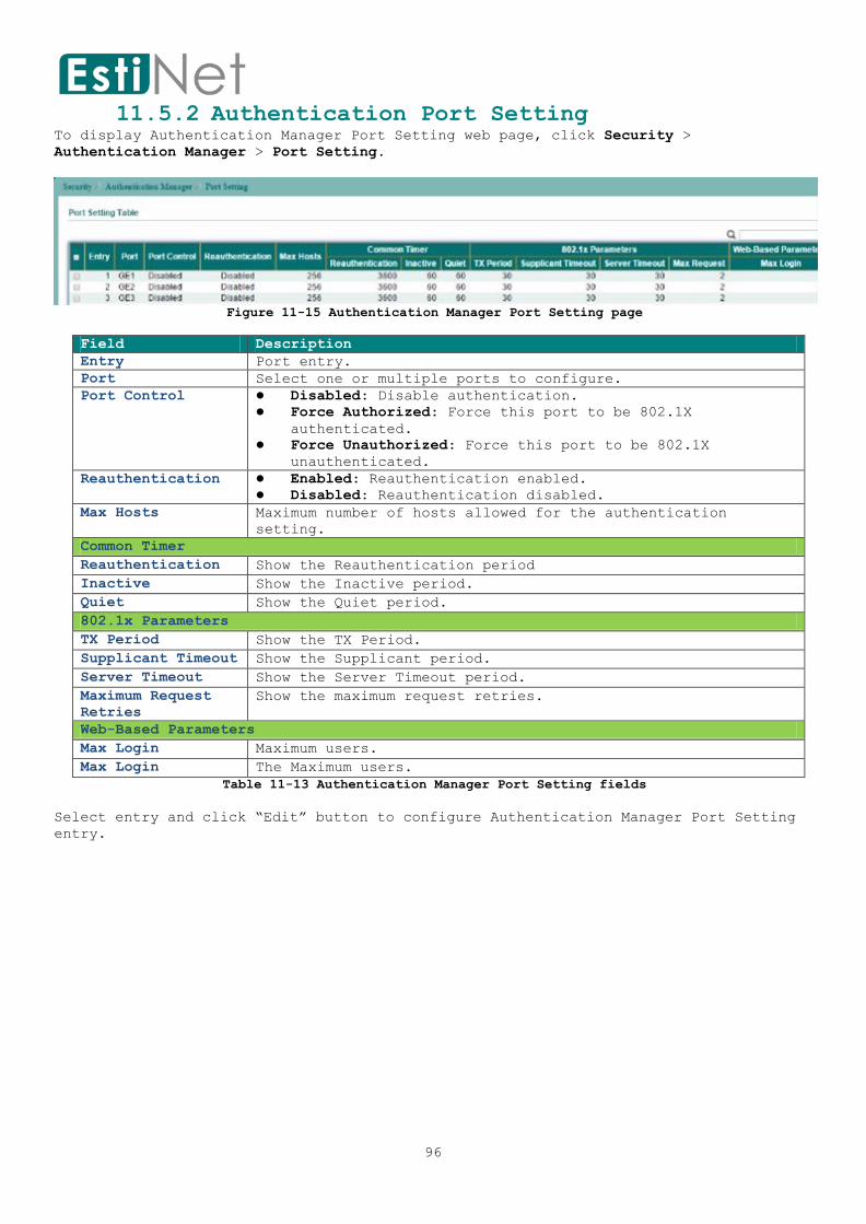
96
11.5.2 Authentication Port Setting To display Authentication Manager Port Setting web page, click Security >
Authentication Manager > Port Setting.
Figure 11-15 Authentication Manager Port Setting page
Field Description
Entry Port entry.
Port Select one or multiple ports to configure.
Port Control Disabled: Disable authentication.
Force Authorized: Force this port to be 802.1X
authenticated.
Force Unauthorized: Force this port to be 802.1X
unauthenticated.
Reauthentication Enabled: Reauthentication enabled.
Disabled: Reauthentication disabled.
Max Hosts Maximum number of hosts allowed for the authentication
setting.
Common Timer
Reauthentication Show the Reauthentication period
Inactive Show the Inactive period.
Quiet Show the Quiet period.
802.1x Parameters
TX Period Show the TX Period.
Supplicant Timeout Show the Supplicant period.
Server Timeout Show the Server Timeout period.
Maximum Request
Retries
Show the maximum request retries.
Web-Based Parameters
Max Login Maximum users.
Max Login The Maximum users.
Table 11-13 Authentication Manager Port Setting fields
Select entry and click “Edit” button to configure Authentication Manager Port Setting
entry.

97
Figure 11-16 Edit Authentication Manager Port Setting page
Field Description
Port Select one or multiple ports to configure.
Port Control Disabled: Disable authentication.
Force Authorized: Force this port to be 802.1X
authenticated.
Force Unauthorized: Force this port to be 802.1X
unauthenticated.
Reauthentication Enabled: Enable reauthentication.
Max Hosts Maximum number of hosts allowed for the authentication
setting.
Common Timer
Reauthentication Set the Reauthentication period.
Inactive Set the Inactive period.
Quiet Set the Quiet period.
802.1x Parameters
TX Period Set the TX Period.
Supplicant Timeout Set the Supplicant period.
Server Timeout Set the Server Timeout period.
Maximum Request
Retries
Set the maximum request retries.
Web-Based Parameters
Max Login The Maximum users.
Table 11-14 Edit Authentication Manager Port Setting fields

98
11.5.3 MAC-Based Local Account To display MAC-Based Local Account web page, click Security > Authentication Manager >
MAC-Based Local Account.
This page allow user to add MAC-Based Local Accounts base on the users' MAC address.
Figure 11-17 MAC-Base Local Account page
Click “Add” button to create a new MAC-Based Local Account entry.
Figure 11-18 Add MAC-Base Local Account page
Field Description
Mac Address The Mac Address of this host.
Port Control Authentication Method
Force Authorized: Force this port to be 802.1X
authenticated.
Force Unauthorized: Force this port to be 802.1X
unauthenticated.
VLAN VLAN ID.
AssignedTime
Reauthentication Set the Reauthentication period.
Inactive Set the Inactive period.
Table 11-15 Add MAC-Base Local Account fields

99
11.5.4 Web-Based Local Account To display Web-Based Local Account web page, click Security > Authentication Manager >
Web-Based Local Account.
Figure 11-19 Web-Base Local Account page
Click “Add” button to create a new WEB-Based Local Account entry.
Figure 11-20 Add Web-Base Local Account page
Field Description
Username Create a user name for Web-Base Local Account.
Password Set the user password
Confirm Password Retype password to make sure the password is exactly you typed
before in “Password” field.
VLAN VLAN ID.
AssignedTime
Reauthentication Set the Reauthentication period.
Inactive Set the Inactive period.
Table 11-16 Add Web-Base Local Account fields

100
11.5.5 Sessions To display Sessions web page, click Security > Authentication Manager > Sessions.
This page shows user about Sessions information.
Figure 11-21 Authentication Manager Sessions page

101
11.6 Port Security To display Port Security web page, click Security > Port Security.
This page allow user to configure port security settings for each interface. When port
security is enabled on interface, action will be perform once learned MAC address over
limitation.
Figure 11-22 Port Security page
Select entry and click “Edit” button to configure Port Security entry.
Figure 11-23 Edit Port Security page
Field Description
Port Select one or multiple ports to configure.
State Enable: Enable port security function.
MAC Address Specify the number of how many MAC addresses can be
learned.
Action Select the action if learned MAC addresses.
Forward: Forward this packet whose MAC is new to
system and exceed the learning-limit number.
Discard: Discard this packet whose MAC is new to
system and exceed the learning-limit number.
Shutdown: Shutdown this port when receives a packet
whose MAC is new to system and exceed the learning
limit number.
Table 11-17 Port Security fields

102
11.7 Protected Ports To display Protected Ports web page, click Security > Protected Ports.
This page allow user to configure protected port setting to prevent the selected ports
from communication with each other.
Protected port is only allowed to communicate with unprotected port. In other words,
protected port is not allowed to communicate with another protected port.
Figure 11-24 Protected Port page
Select entry and click “Edit” button to configure Protected Port entry.
Figure 11-25 Edit Protected Port page
Field Description
Port Select one or multiple ports to configure.
State Protected: Enable Protected Port function.
Table 11-18 Protected Port fields

103
11.8 Storm Control To display Storm Control setting web page, click Security > Storm Control.
Figure 11-26 Storm Control page
Field Description
Mode Select the unit of storm control.
Packet/Sec: Storm control rate calculates by packet-based.
Kbits/Sec: Storm control rate calculates by octet-based.
IFG Select the rate calculates w/o preamble & IFG (20 bytes)
Excluded: exclude preamble & IFG (20 bytes) when count
ingress storm control rate.
Included: include preamble & IFG (20 bytes) when count
ingress storm control rate.
Table 11-19 Storm Control fields
Select entry and click “Edit” button to configure Storm Control entry.

104
Figure 11-27 Edit Storm Control page
Field Description
Port Selected port.
State Enable: Enable the storm control function.
Broadcast Enable: Enable Broadcast packet Storm Control.
Value of storm control rate, Unit: pps (packet per-second) or
Kbps (Kbits per-second) depends on global mode setting.
The range is from 0 to 1000000.
Unknown Multicast Enable: Enable Unknown Multicast packet Storm Control.
Value of storm control rate, Unit: pps (packet per-second) or
Kbps (Kbits per-second) depends on global mode setting.
The range is from 0 to 1000000.
Unknown Unicast Enable: Enable Unknown Unicast packet Storm Control.
Value of storm control rate, Unit: pps (packet per-second) or
Kbps (Kbits per-second) depends on global mode setting.
The range is from 0 to 1000000.
Action Select the state of setting
Drop: Packets exceed storm control rate will be dropped.
Shutdown: Port will be shutdown when packets exceed storm
control rate.
Table 11-20 Edit Storm Control fields

105
11.9 DoS A Denial of Service (DoS) attack is a hacker attempt to make a device unavailable to
its users. DoS attacks saturate the device with external communication requests, so
that it cannot respond to legitimate traffic. These attacks usually lead to a device
CPU overload.
The DoS protection feature is a set of predefined rules that protect the network from
malicious attacks. The DoS Security Suite Settings enables activating the security
suite.
11.9.1 Dos Property To display Dos Global Setting web page, click Security > DoS > Property.
Figure 11-28 DoS Property page

106
Field Description
POD Avoids ping of death attack.
Land Drops the packets if the source IP address is equal to the
destination IP address.
UDP Blat Drops the packets if the UDP source port equals to the UDP
destination port.
TCP Blat Drops the packages if the TCP source port is equal to the TCP
destination port.
DMAC = SMAC Drops the packets if the destination MAC address is equal to
the source MAC address.
Null Scan Attach Drops the packets with NULL scan.
X-Mas Scan Attack Drops the packets if the sequence number is zero, and the FIN,
URG and PSH bits are set.
TCP-
SYN(SPORT<1024)
Drops SYN packets with sport less than 1024.
TCP SYN-FIN
Attack
Drops the packets with SYN and FIN bits set.
TCP SYN-RST
Attack
Drops the packets with SYN and RST bits set.
ICMP Fragment Drops the fragmented ICMP packets.
TCP Fragment Drops the TCP fragment packets with offset equals to one.
Ping Max Size IPv4 Ping Max Size: Checks the maximum size of ICMP ping
packets, and drops the packets larger than the maximum packet
size.
IPv6 Ping Max Size: Checks the maximum size of ICMPv6 ping
packets, and drops the packets larger than the maximum packet
size.
Ping Max Size Specify the maximum size of the ICMPv4/ICMPv6
ping packets. The valid range is from 0 to 65535 bytes, and the
default value is 512 bytes.
TCP Min Hdr Size Checks the minimum TCP header and drops the TCP packets with
the header smaller than the minimum size. The length range is
from 0 to 31 bytes, and default length is 20 bytes.
IPv6 Min Fragment Checks the minimum size of IPv6 fragments, and drops the
packets smaller than the minimum size. The valid range is from
0 to 65535 bytes, and default value is 1240 bytes.
Smurf Attack Avoids smurf attack. The length range of the netmask is from 0
to 323 bytes, and default length is 0 bytes.
Table 11.9.1 DoS Property fields
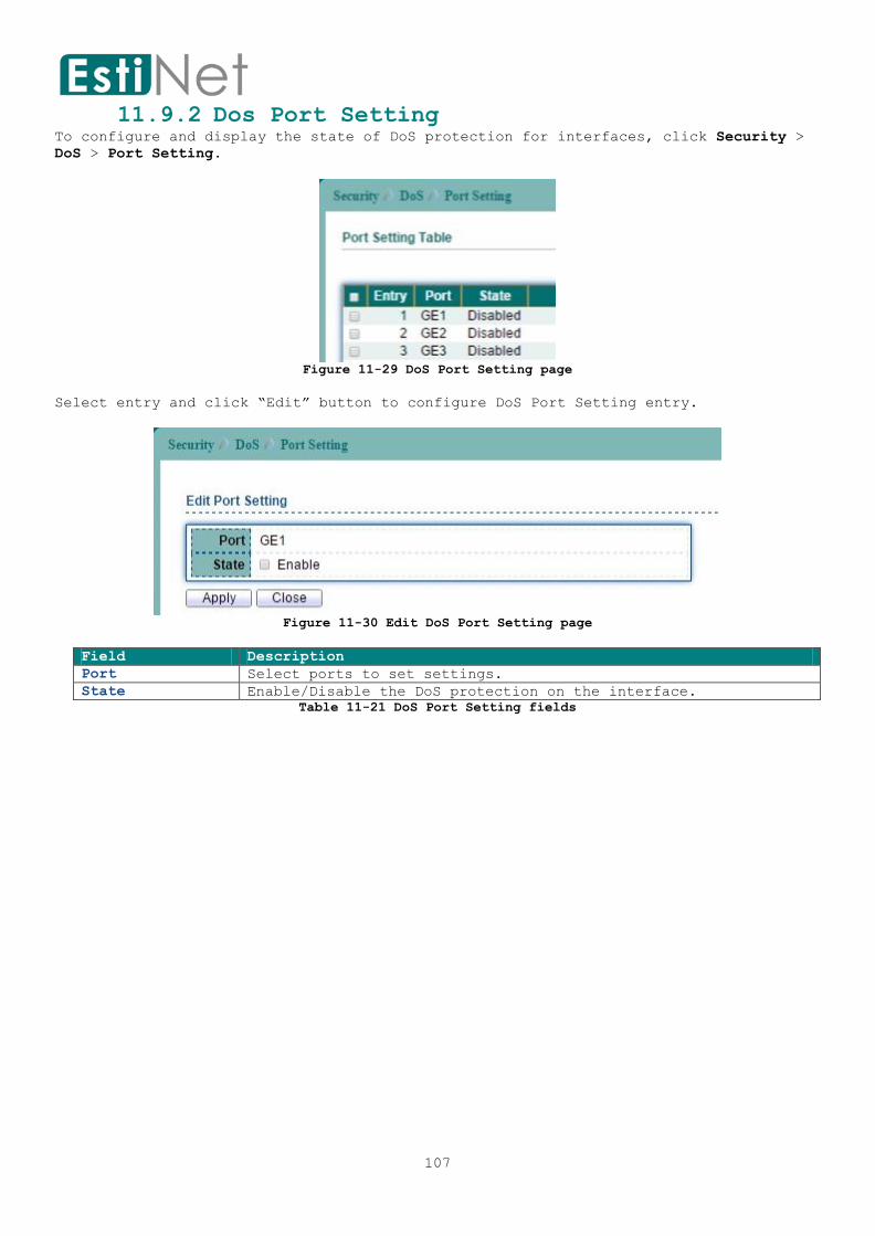
107
11.9.2 Dos Port Setting To configure and display the state of DoS protection for interfaces, click Security >
DoS > Port Setting.
Figure 11-29 DoS Port Setting page
Select entry and click “Edit” button to configure DoS Port Setting entry.
Figure 11-30 Edit DoS Port Setting page
Field Description
Port Select ports to set settings.
State Enable/Disable the DoS protection on the interface.
Table 11-21 DoS Port Setting fields

108
11.10 Dynamic ARP Inspection 11.10.1 DAI property
To display Dynamic ARP Inspection Setting web page, click Security > Dynamic ARP
Inspection > Statistics.
This page allow user to enable/disable DAI function.
Figure 11-31 DAI Property page
Field Description
State To enable or disable dynamic Arp inspection function. Default
is that all VLAN disabled.
VLAN LIST Select VLAN from the Available VLAN list to enable or disable
dynamic Arp inspection function.
Table 11-22 DAI Property fields
Select entry and click “Edit” button to configure DAI Port Setting entry.
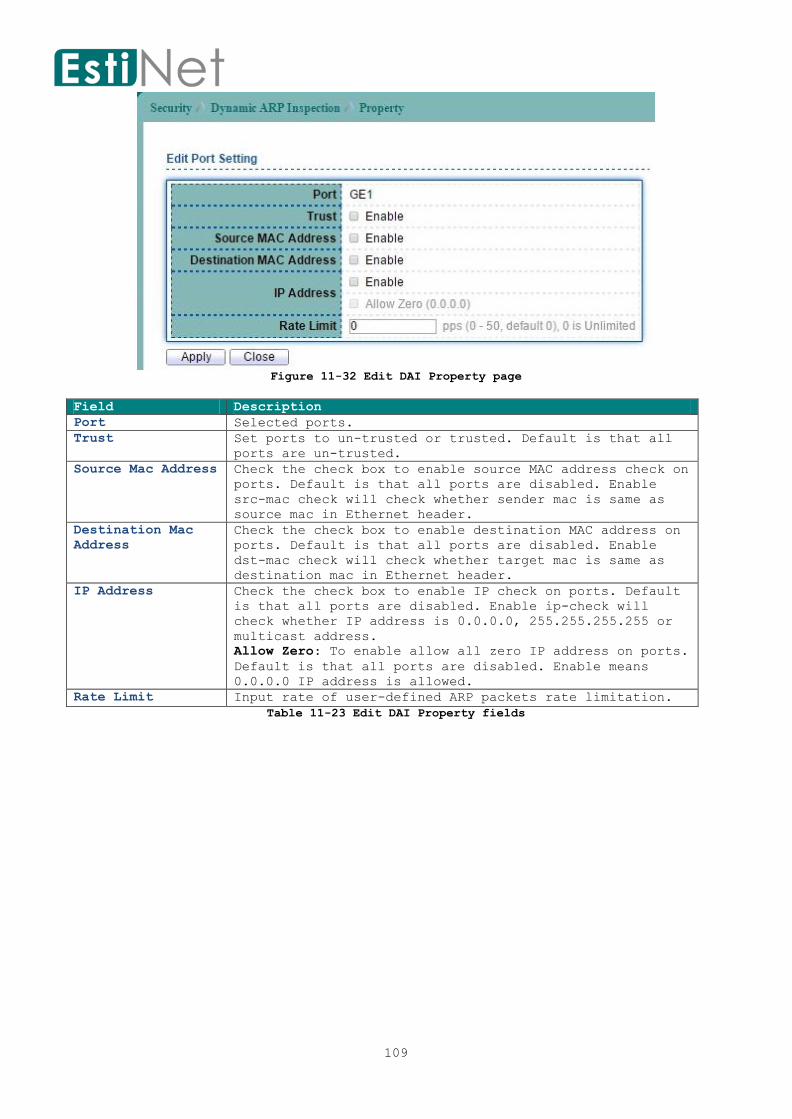
109
Figure 11-32 Edit DAI Property page
Field Description
Port Selected ports.
Trust Set ports to un-trusted or trusted. Default is that all
ports are un-trusted.
Source Mac Address Check the check box to enable source MAC address check on
ports. Default is that all ports are disabled. Enable
src-mac check will check whether sender mac is same as
source mac in Ethernet header.
Destination Mac
Address
Check the check box to enable destination MAC address on
ports. Default is that all ports are disabled. Enable
dst-mac check will check whether target mac is same as
destination mac in Ethernet header.
IP Address Check the check box to enable IP check on ports. Default
is that all ports are disabled. Enable ip-check will
check whether IP address is 0.0.0.0, 255.255.255.255 or
multicast address.
Allow Zero: To enable allow all zero IP address on ports.
Default is that all ports are disabled. Enable means
0.0.0.0 IP address is allowed.
Rate Limit Input rate of user-defined ARP packets rate limitation.
Table 11-23 Edit DAI Property fields

110
11.10.2 Dynamic ARP Inspection Statistics To display Dynamic ARP Inspection Statistics web page, click Security > Dynamic ARP
Inspection > Statistics.
Figure 11-33 DAI Statistics page

111
11.11 DHCP Snooping
11.11.1 Property To display DHCP Snooping Setting web page, click Security > DHCP Snooping > Property.
This page allow user to enable or disable DHCP snooping function.
Figure 11-34 DHCP Snooping Property page
Field Description
State To enable DHCP Snooping function. Default is disabled.
VLAN Select VLAN from the Available VLAN list to enable or disable
DHCP Snooping function.
Figure 11-35 DHCP Snooping Property fields
Select entry and click “Edit” button to configure DHCP Snooping Port Setting entry.
Figure 11-36 Edit DHCP Snooping Property page

112
Field Description
Port Selected port.
Trust Set ports to trusted status. Default is that all ports are
un-trusted.
Verify Chaddr To enable chaddr check on ports. Default is that all ports
are disabled. Enable this feature will check whether chaddr
in DHCP request packet same as source MAC address of Ethernet
header.
Rate Limit DHCP packets rate limit. Packets will be drop if over rate
limitation.
Figure 11-37 Edit DHCP Snooping Property fields

113
11.11.2 Statistics
To display DHCP Snooping Setting web page, click Security > DHCP Snooping > Statistic.
This page allow user to browse all statistics that recorded by DHCP snooping function.
Figure 11-38 DHCP Snooping Statistics page
Field Description
Port Interface Ports.
Forwarded Show how packets forwarded normally.
Chaddr Check Drop Show how many packets dropped by chaddr checking.
Untrusted Port
Drop
Show how many DHCP server packets that are received by
untrusted port dropped.
Untrusted Port
with Option82 Drop
Show how many packets dropped by untrusted port with option82
checking.
Invalid Drop Show how many packets dropped by invalid drop.
Table 11-24 DHCP Snooping Statistics fields

114
11.11.3 Option82 Property To display DHCP Snooping Option 82 Setting web page, click Security > DHCP Snooping >
Option82 Property.
This page allow user to set string of DHCP option82 remote ID filed. The string will
attach in option82 if option inserted.
Figure 11-39 DHCP Snooping Option82 Property page
Field Description
Option82 Remote ID Check the check box to default or user defined remote ID.
Default is device MAC address in format.
Table 11-25 DHCP Snooping Option82 fields
Select entry and click “Edit” button to configure DHCP Snooping Option82 Port Setting
entry.
Figure 11-40 Edit DHCP Snooping Option82 Property page
Field Description
Port Selected ports.
State To enable option82 function on ports.
Allow Untrust Select the action perform when untrusted port receive
DHCP packet has option82 filed. Default is drop.

115
Keep: Keep original option82 content.
Drop: Drop packets with option82.
Replace: Replace option82 content by switch setting.
Table 11-26 Edit DHCP Snooping Option82 Property fields

116
11.11.4 Option82 Circuit ID Setting To display DHCP Snooping Option82 Setting web page, click Security > DHCP Snooping >
Option82 Circuit ID.
Figure 11-41 DHCP Snooping Option82 Circuit-ID page
Click “Add” button to create DHCP Snooping Option82 Circuit ID entry.
Figure 11-42 Add DHCP Snooping Option82 Circuit-ID page
Field Description
Port Select ports to set settings.
VLAN Input VLAN list.
Circuit ID Input user defined circuit ID string.
Table 11-27 DHCP Snooping Option82 Circuit-ID fields
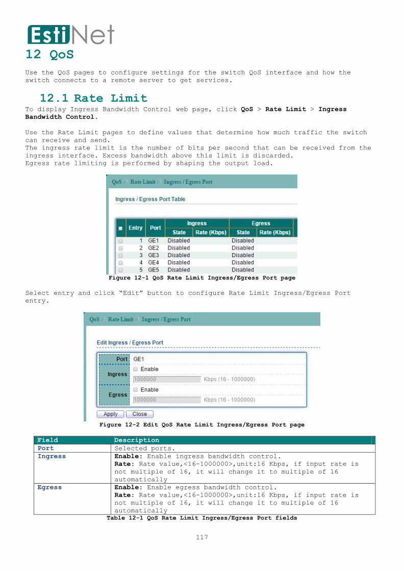
117
12 QoS
Use the QoS pages to configure settings for the switch QoS interface and how the
switch connects to a remote server to get services.
12.1 Rate Limit To display Ingress Bandwidth Control web page, click QoS > Rate Limit > Ingress
Bandwidth Control.
Use the Rate Limit pages to define values that determine how much traffic the switch
can receive and send.
The ingress rate limit is the number of bits per second that can be received from the
ingress interface. Excess bandwidth above this limit is discarded.
Egress rate limiting is performed by shaping the output load.
Figure 12-1 QoS Rate Limit Ingress/Egress Port page
Select entry and click “Edit” button to configure Rate Limit Ingress/Egress Port
entry.
Figure 12-2 Edit QoS Rate Limit Ingress/Egress Port page
Field Description
Port Selected ports.
Ingress Enable: Enable ingress bandwidth control.
Rate: Rate value,<16-1000000>,unit:16 Kbps, if input rate is
not multiple of 16, it will change it to multiple of 16
automatically
Egress Enable: Enable egress bandwidth control.
Rate: Rate value,<16-1000000>,unit:16 Kbps, if input rate is
not multiple of 16, it will change it to multiple of 16
automatically
Table 12-1 QoS Rate Limit Ingress/Egress Port fields

118
13 Diagnostics
Use the Diagnostics pages to configure settings for the switch diagnostics feature or
operating diagnostic utilities.
13.1 Logging 13.1.1 Logging Property
To enable/disable the logging service, click Diagnostics > Logging > Property.
Figure 13-1 Logging Property page
Field Description
State Enable/Disable the global logging services. When the
logging service is enabled, logging configuration of each
destination rule can be individually configured. If the
logging service is disabled, no messages will be sent to
these destinations.
Console Logging Enable: Print the logging messages on the console.
Minimum Severity: Specify the minimum severity of the
logging messages.
Emergency: System is not usable.
Alert: Immediate action is needed.
Critical: System is in the critical condition.
Error: System is in error condition
Warning: System warning has occurred
Notice: System is functioning properly, but a system
notice has occurred.
Information: Device information.
Debug: Provides detailed information about an event.
RAM Logging Enable: Store the logging messages on the RAM.
Minimum Severity: Specify the minimum severity of the
logging messages.
Emergency: System is not usable.

119
Alert: Immediate action is needed.
Critical: System is in the critical condition.
Error: System is in error condition
Warning: System warning has occurred
Notice: System is functioning properly, but a system
notice has occurred.
Information: Device information.
Debug: Provides detailed information about an event.
Flash Logging Enable: Store the logging messages on the Flash.
Minimum Severity: Specify the minimum severity of the
logging messages.
Emergency: System is not usable.
Alert: Immediate action is needed.
Critical: System is in the critical condition.
Error: System is in error condition
Warning: System warning has occurred
Notice: System is functioning properly, but a system
notice has occurred.
Information: Device information.
Debug: Provides detailed information about an event.
Table 13-1 Logging Property fields

120
13.1.2 Remote Server To configure the remote logging service, click Diagnostics > Logging > Remote Server.
Figure 13-2 Logging Remote Server page
Click “Add” button to create a new Logging Remote Server entry.
Figure 13-3 Add Logging Remote Server page
Field Description
Address Type IPv4/IPv6 address or hostname of the remote logging
server.
Server Address Logging Server IP address or hostname.
Server Ports Specify the port number of the remote logging server.
The valid range is from 0 to 65535, and the default
value is 514.
Facility Specify the facility of the logging messages. It can be
one of the following value: local0, local1, local2,
local3, local4, local5, local6, and local7.
Minimum Severity Specify the minimum severity of the logging messages.
Emergency: System is not usable.
Alert: Immediate action is needed.
Critical: System is in the critical condition.
Error: System is in error condition
Warning: System warning has occurred
Notice: System is functioning properly, but a system
notice has occurred.
Information: Device information.
Debug: Provides detailed information about an event.
Table 13-2 Logging Remote Server fields

121
13.2 Mirroring Setting To display Port Mirroring web page, click Diagnostics>Mirroring.
Figure 13-4 Mirroring page
Select entry and click “Edit” button to configure Mirroring entry.
Figure 13-5 Edit Mirroring page

122
Field Description
Session ID Select mirror session ID
State Enabled: Enable port based mirror
Monitor Port Select mirror session destination port
Ingress ports Select mirror session source Ingress (rx) ports.
Egress ports Select mirror session source Egress (tx) ports
Table 13-3 Mirroring fields

123
13.3 Ping To use the ping test functionality, click Diagnostics > Ping.
Figure 13-6 Ping page
Field Description
Address Type Specify the IP Type.
Server Address Specify the IPv4/IPv6 address or Hostname.
Count User Define: Specify the total numbers of ICMP ping packets
to be sent.
Ping Results The field for the result of the ICMP ping test.
Table 13-4 Ping fields
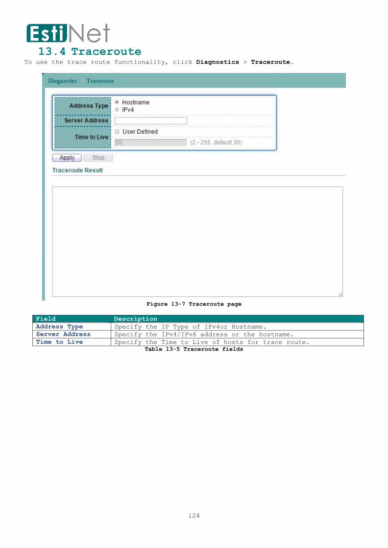
124
13.4 Traceroute To use the trace route functionality, click Diagnostics > Traceroute.
Figure 13-7 Traceroute page
Field Description
Address Type Specify the IP Type of IPv4or Hostname.
Server Address Specify the IPv4/IPv6 address or the hostname.
Time to Live Specify the Time to Live of hosts for trace route.
Table 13-5 Traceroute fields

125
13.5 Copper Test To perform the copper length diagnostic, click Diagnostics > Copper Test.
Figure 13-8 Copper Test page
Field Description
Port Interface or port number.
Cooper Test Result
Port Selected Port.
Result Display whether port test is Pass or Fail.
Length Distance in meter from the port to the location on the cable
where the fault was discovered.
Table 13-6 Copper Test fields

126
13.6 Fiber Module The Optical Module Status page displays the operational information reported by the
Small Form-factor Pluggable (SFP) transceiver. Some information may not be available
for SFPs without the supports of digital diagnostic monitoring standard SFF-8472.
To display the Optical Module Diagnostic page, click Diagnostics > Fiber Module.
Figure 13-9 Fiber Module page
Field Description
Port Interface or port number.
Temperature Internally measured transceiver temperature.
Voltage (V) Internally measured supply voltage.
Current (mA) Measured TX bias current.
Output Power (mW) Measured TX output power in milliwatts.
Input Power (mW) Measured RX received power in milliwatts.
Data Ready Indicate transceiver has achieved power up and data is ready.
Transmitter Fault State of TX fault.
Loss of Signal Loss of signal.
Table 13-7 Fiber Module fields

127
13.7 UDLD
13.7.1 UDLD Property To configure the Unidirectional Link Detection (UDLD), click Diagnostics > UDLD >
Property.
User can UDLD function to detect the unidirectional link exits on the network. All
connected devices must support UDLD protocol to make this function successfully.
Figure 13-10 UDLD Property page
Select entry and click “Edit” button to configure UDLD Port Setting entry.
Figure 13-11 Edit UDLD Property page
Field Description
Port Port number.
Mode UDLD Mode.
Bidirectional
State
Bidirectional State information.
Operational Status Operational State information.
Neighbor UDLD Neighbor information.
Edit Port Setting
Port Selected port.
Mode Select one of UDLD Modes or disable it.
Normal: UDLD Normal mode; use to detect unidirectional
links due to misconnected interface on fiber-optical
connection.
Aggressive: UDLD Aggressive mode: use to detect
unidirectional links due to misconnected interface on
fiber-optical connection and unidirectional links due to
one-way traffic on fiber-optic and twisted-pair links.
Table 13-8 UDLD Property fields

128
13.7.2 UDLD Neighbor To display the Unidirectional Link Detection (UDLD) Neighbor information, click
Diagnostics > UDLD > Neighbor.
Figure 13-12 UDLD Neighbor page

129
14 Management
Use the Management pages to configure settings for the switch network interface and
how the switch connects to a remote server to get services.
14.1 User Account To display User Account web page, click Management > User Account.
The default username/password is switch/admin. And default account is not able to be
deleted.
Use this page to add additional users that are permitted to manage the switch or to
change the passwords of existing users.
Figure 14-1 User Account page
Click “Add” button to create a new User Account entry.
Figure 14-2 Add User Account page
Field Description
User Name User name for new account.
Password Specify a password for the user account.
Confirm Password Retype password to make sure the password is exactly you typed
before in “Password” field.
Privilege Select privilege level for new account.
Admin: Allow to change switch settings.
User: See switch settings only. Not allow to change it.
Table 14-1 Add User Account fields

130
14.2 Firmware
14.2.1 Upgrade/Backup To display Upgrade/Backup Manager web page, click Management > Firmware >
Upgrade/Backup.
This page allow user to Upgrade/backup the firmware image on the switch to remote TFTP
server or host file system through HTTP protocol.
Figure 14-3 Firmware Upgrade/Backup page
Figure 14-4 Firmware Upgrade/Backup page
Field Description
Action Select an Action to Upgrade or Backup the firmware.
Method Select upgrade/backup method.
TFTP: Use TFTP to upgrade/backup.
HTTP: Use HTTP to upgrade/backup.
TFTP
Address Type Server Address Type
Host name: Use host name as server address.
IPv4 address: Use IPv4 address as server address.
IPv6 address: Use IPv6 address as server address.
Server Address IP address of the TFTP server. If the TFTP backup method is
selected, the IP address of the TFTP server must be assigned.
Filename Firmware image or configuration file name on remote TFTP server.
If the TFTP upgrade method is selected, the file name must be
specified.
HTTP
Filename If the HTTP upgrade method is selected, the browse file field
allow you to select any file on host operating system.
Table 14-2 Firmware Upgrade/Backup fields
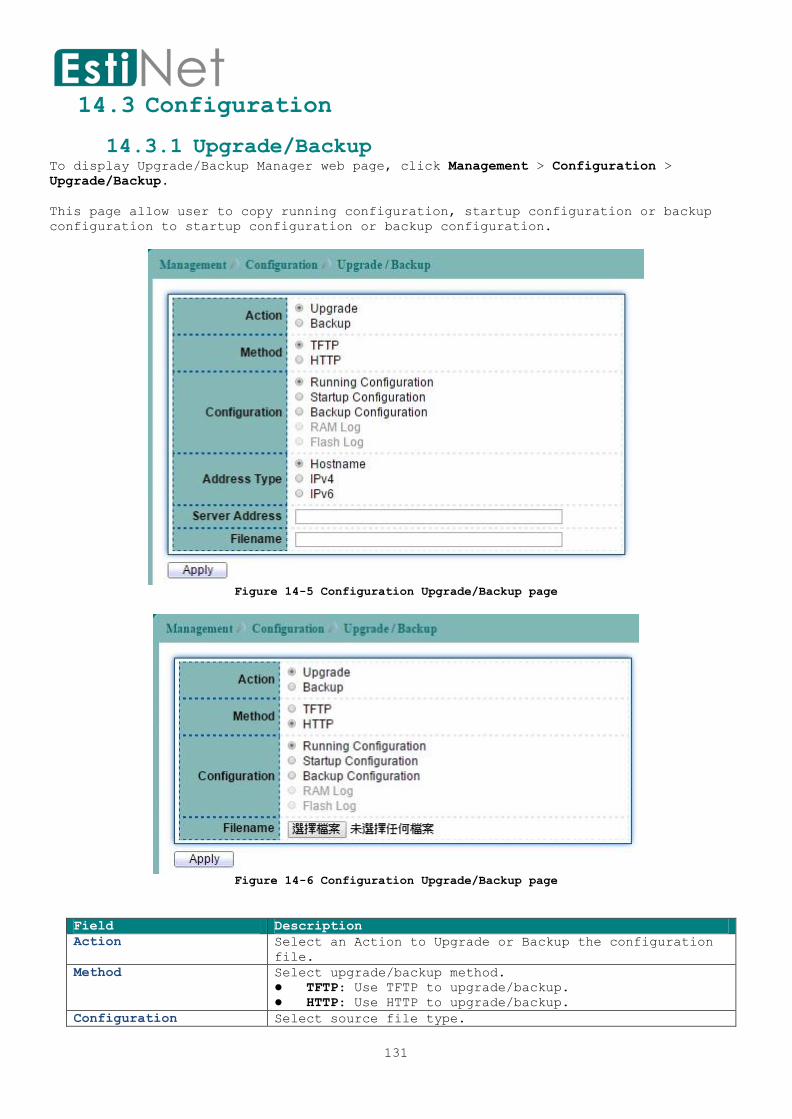
131
14.3 Configuration
14.3.1 Upgrade/Backup To display Upgrade/Backup Manager web page, click Management > Configuration >
Upgrade/Backup.
This page allow user to copy running configuration, startup configuration or backup
configuration to startup configuration or backup configuration.
Figure 14-5 Configuration Upgrade/Backup page
Figure 14-6 Configuration Upgrade/Backup page
Field Description
Action Select an Action to Upgrade or Backup the configuration
file.
Method Select upgrade/backup method.
TFTP: Use TFTP to upgrade/backup.
HTTP: Use HTTP to upgrade/backup.
Configuration Select source file type.

132
Running configuration: Running configuration file.
Startup configuration: Startup configuration file.
Backup configuration: Backup configuration file.
RAM Log: Backup RAM Log.
Flash Log: Backup Flash Log.
TFTP
Address Type Server Address Type
Host name: Use host name as server address.
IPv4 address: Use IPv4 address as server address.
IPv6 address: Use IPv6 address as server address.
Server Address IP address of the TFTP server. If the TFTP backup method
is selected, the IP address of the TFTP server must be
assigned.
Filename Configuration file name on remote TFTP server. If the
TFTP upgrade method is selected, the file name must be
specified.
HTTP
Filename If the HTTP upgrade method is selected, the browse file
field allow you to select any file on host operating
system.
Table 14-3 Configuration Upgrade/Backup fields

133
14.3.2 Save Configuration To display Save Configuration web page, click Management > Configuration > Save
Configuration.
This page allow user to copy running configuration, startup configuration or backup
configuration to startup configuration or backup configuration. And restore the switch
factory default setting.
Figure 14-7 Save Configuration page
Field Description
Source File Select source file type.
Running configuration: Running configuration file.
Startup configuration: Startup configuration file.
Backup configuration: Backup configuration file.
Destination File Select destination file type.
Startup Configuration: Startup configuration file.
Backup Configuration: Backup configuration file.
Table 14-4 Save Configuration fields

134
14.4 SNMP
14.4.1 SNMP View To configure and display the SNMP view settings, click Management > SNMP > View.
Figure 14-8 SNMP View page
Click “Add” button to create a new SNMP View entry.
Figure 14-9 Add SNMP View page
Field Description
View Name The SNMP view name. Its maximum length is 30 characters.
OID Subtree Specify the ASN.1 subtree object identifier (OID) to be
included or excluded from the SNMP view
Type Include or exclude the selected MIBs in the view.
Table 14-5 SNMP View fields
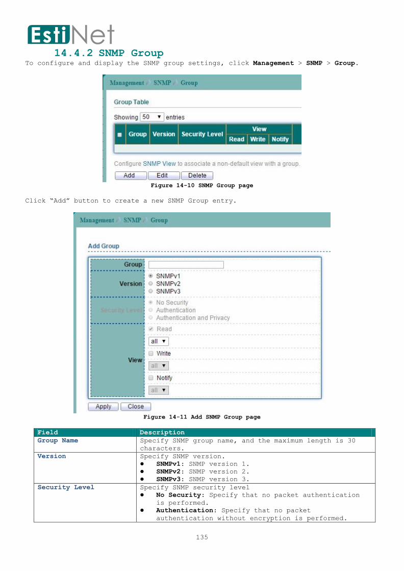
135
14.4.2 SNMP Group To configure and display the SNMP group settings, click Management > SNMP > Group.
Figure 14-10 SNMP Group page
Click “Add” button to create a new SNMP Group entry.
Figure 14-11 Add SNMP Group page
Field Description
Group Name Specify SNMP group name, and the maximum length is 30
characters.
Version Specify SNMP version.
SNMPv1: SNMP version 1.
SNMPv2: SNMP version 2.
SNMPv3: SNMP version 3.
Security Level Specify SNMP security level
No Security: Specify that no packet authentication
is performed.
Authentication: Specify that no packet
authentication without encryption is performed.

136
Authentication and Privacy: Specify that no packet
authentication with encryption is performed.
View Read: Select the view name and enables viewing only.
Write: Select the view name and enables configuring
the agent.
Notify: Select view name that sends only traps with
contents that is included in SNMP view selected for
notification.
Table 14-6 SNMP Group fields

137
14.4.3 SNMP Community To configure and display the SNMP community settings, click Management > SNMP >
Community.
Figure 14-12 SNMP Community page
Click “Add” button to create a new SNMP Community entry.
Figure 14-13 Add SNMP Community page
Field Description
Community Name The SNMP community name. Its maximum length is 20
characters.
Type SNMP Community Type.
Basic: SNMP community specifies view and access right.
Advanced: SNMP community specifies group.
View Specify the SNMP view to define the object available to the
community.
Access Right SNMP access mode
Read-Only: Read only.
Read-Write: Read and write.
Group Specify the SNMP group configured by the command snmp group
to define the object available to the community.
Table 14-7 SNMP community fields

138
14.4.4 SNMP User To configure and display the SNMP users, click Management > SNMP > User.
Figure 14-14 SNMP User page
Click “Add” button to create a new SNMP User entry.
Figure 14-15 Add SNMP User page
Field Description
User Specify the SNMP user name on the host that connects to
the SNMP agent. The max character is 30 characters. For
the SNMP v1 or v2c, the user name must match the
community name.
Group Specify the SNMP group to which the SNMP user belongs.
Authentication
Method Authentication Protocol which is available when
Privilege Mode is Authentication or privacy.
None: No authentication required.
MD5: Specify the HMAC-MD5-96 authentication

139
protocol.
SHA: Specify the HMAC-SHA-96 authentication
protocol.
Password The password for authentication and the range of length
is from 8 to 32 characters.
Privacy
Method Encryption Protocol
None: No privacy required.
DES: DES algorithm.
Password Encryption password. The range of length is from 8 to 64
characters.
Table 14-8 SNMP User fields

140
14.4.5 SNMP Engine ID
To configure and display SNMP engine ID and remote engine ID, click Management > SNMP
> Engine ID.
Table 14-9 SNMP Engine ID page
Click “Add” button to create a new SNMP Engine ID entry.
Figure 14-16 Add SNMP Engine ID page
Field Description
Engine ID User Defined: Specify SNMP engine ID. The engine ID is the
10 to 64 hexadecimal characters.
Add Remote Engine ID
Address Type Server Address Type
Host name: Use host name as server address.
IPv4 address: Use IPv4 address as server address.
IPv6 address: Use IPv6 address as server address.
Server Address The IP address or the hostname of the SNMP trap
recipients.
Engine ID Specify SNMP engine ID. The engine ID is the 10 to 64
hexadecimal character.
Table 14-10 SNMP Engine ID fields

141
14.4.6 SNMP Trap Event To configure SNMP Trap Event, click Management > SNMP > Trap Event.
Switch will send the trap message when one of following condition selected and
occurred.
Figure 14-17 SNMP Trap Event page
Field Description
Authentication
Failure
Send the trap message when authentication failed.
Link UP/Down Send the trap message when port is link up/down.
Cold Start Send the trap message when system cold start occurred.
Warm Start Send the trap message when system warm start occurred.
Table 14-11 SNMP Trap Event fields

142
14.4.7 SNMP Notification To configure the hosts to receive SNMP notifications, click Management > SNMP >
Notification.
Figure 14-18 SNMP Notification page
Click “Add” button to create a new SNMP Notification entry.
Figure 14-19 Add SNMP Notification page
Field Description
Address Type Server Address Type
Host name: Use host name as server address.
IPv4 address: Use IPv4 address as server address.
IPv6 address: Use IPv6 address as server address.
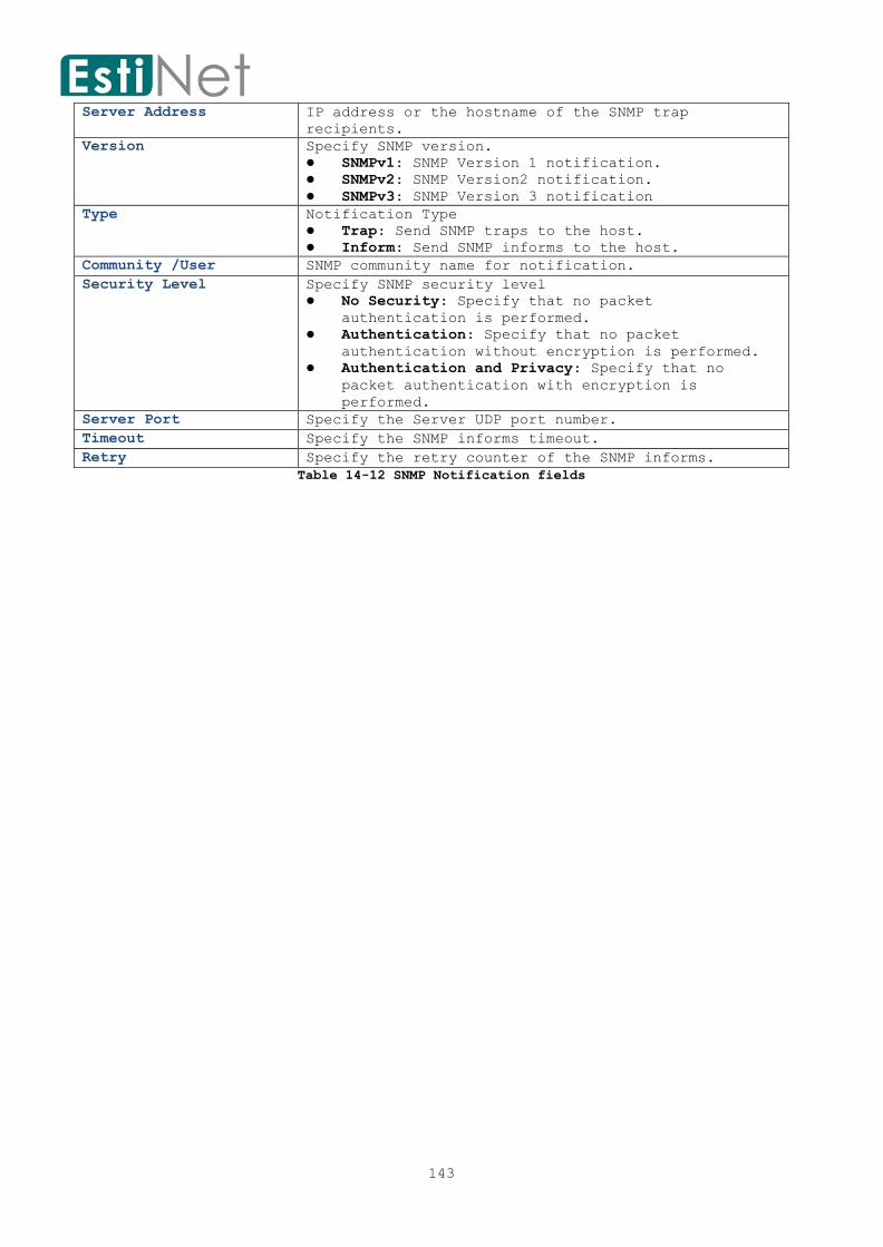
143
Server Address IP address or the hostname of the SNMP trap
recipients.
Version Specify SNMP version.
SNMPv1: SNMP Version 1 notification.
SNMPv2: SNMP Version2 notification.
SNMPv3: SNMP Version 3 notification
Type Notification Type
Trap: Send SNMP traps to the host.
Inform: Send SNMP informs to the host.
Community /User SNMP community name for notification.
Security Level Specify SNMP security level
No Security: Specify that no packet
authentication is performed.
Authentication: Specify that no packet
authentication without encryption is performed.
Authentication and Privacy: Specify that no
packet authentication with encryption is
performed.
Server Port Specify the Server UDP port number.
Timeout Specify the SNMP informs timeout.
Retry Specify the retry counter of the SNMP informs.
Table 14-12 SNMP Notification fields
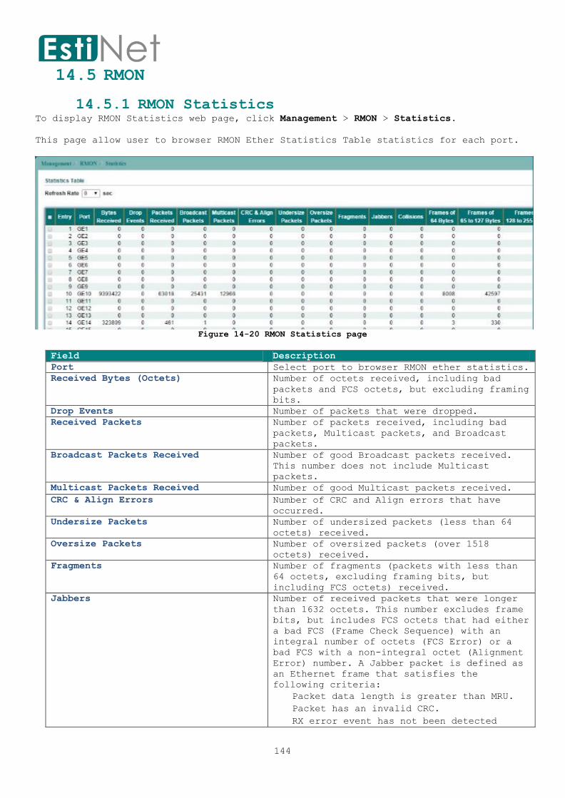
144
14.5 RMON
14.5.1 RMON Statistics To display RMON Statistics web page, click Management > RMON > Statistics.
This page allow user to browser RMON Ether Statistics Table statistics for each port.
Figure 14-20 RMON Statistics page
Field Description
Port Select port to browser RMON ether statistics.
Received Bytes (Octets) Number of octets received, including bad
packets and FCS octets, but excluding framing
bits.
Drop Events Number of packets that were dropped.
Received Packets Number of packets received, including bad
packets, Multicast packets, and Broadcast
packets.
Broadcast Packets Received Number of good Broadcast packets received.
This number does not include Multicast
packets.
Multicast Packets Received Number of good Multicast packets received.
CRC & Align Errors Number of CRC and Align errors that have
occurred.
Undersize Packets Number of undersized packets (less than 64
octets) received.
Oversize Packets Number of oversized packets (over 1518
octets) received.
Fragments Number of fragments (packets with less than
64 octets, excluding framing bits, but
including FCS octets) received.
Jabbers Number of received packets that were longer
than 1632 octets. This number excludes frame
bits, but includes FCS octets that had either
a bad FCS (Frame Check Sequence) with an
integral number of octets (FCS Error) or a
bad FCS with a non-integral octet (Alignment
Error) number. A Jabber packet is defined as
an Ethernet frame that satisfies the
following criteria:
Packet data length is greater than MRU.
Packet has an invalid CRC.
RX error event has not been detected

145
Table 14-13 RMON Statistics fields
Collisions Number of collisions received. If Jumbo
Frames are enabled, the threshold of Jabber
Frames is raised to the maximum size of Jumbo
Frames.
Frame of 64 Bytes Number of frames, containing 64 bytes that
were received.
Frame of 65 to 127 Bytes Number of frames, containing 65 to 127 bytes
that were received.
Frame of 128 to 255 Bytes Number of frames, containing 128 to 255 bytes
that were received.
Frame of 256 to 511 Bytes Number of frames, containing 256 to 511 bytes
that were received.
Frame of 512 to 1023 Bytes Number of frames, containing 512 to 1023
bytes that were received.
Frames Greater than 1024 Bytes Number of frames, containing 1024 to 1518
bytes that were received.
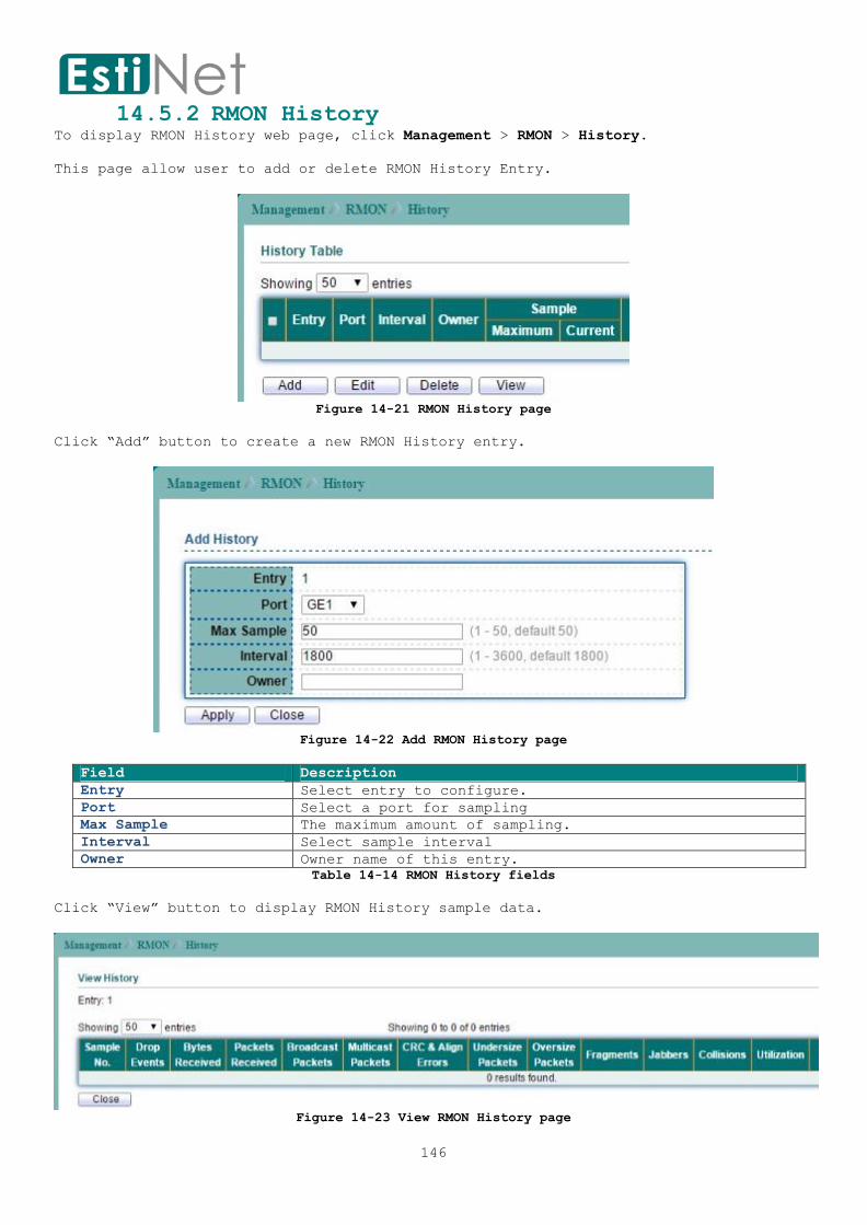
146
14.5.2 RMON History To display RMON History web page, click Management > RMON > History.
This page allow user to add or delete RMON History Entry.
Figure 14-21 RMON History page
Click “Add” button to create a new RMON History entry.
Figure 14-22 Add RMON History page
Field Description
Entry Select entry to configure.
Port Select a port for sampling
Max Sample The maximum amount of sampling.
Interval Select sample interval
Owner Owner name of this entry.
Table 14-14 RMON History fields
Click “View” button to display RMON History sample data.
Figure 14-23 View RMON History page

147
Field Description
Sample No. Sample Numbers.
Drop Events Number of packets that were dropped.
Bytes Received Number of bytes received, including bad packets and FCS
octets, but excluding framing bits
Packets Received Number of packets received, including bad packets, Multicast
packets, and Broadcast packets.
Broadcast Packets Number of good Broadcast packets received. This number does
not include Multicast packets.
Multicast Packets Number of good Multicast packets received.
CRC & Align Errors Number of CRC and Align errors that have occurred.
Undersize Packets Number of undersized packets (less than 64 octets) received.
Oversize Packets Number of oversized packets (over 1518 octets) received.
Fragments Number of fragments (packets with less than 64 octets,
excluding framing bits, but including FCS octets) received.
Jabbers Number of received packets that were longer than 1632 octets.
This number excludes frame bits, but includes FCS octets that
had either a bad FCS (Frame Check Sequence) with an integral
number of octets (FCS Error) or a bad FCS with a non-integral
octet (Alignment Error) number. A Jabber packet is defined as
an Ethernet frame that satisfies the following criteria:
Packet data length is greater than MRU.
Packet has an invalid CRC.
RX error event has not been detected.
Collisions Number of collisions received. If Jumbo Frames are enabled,
the threshold of Jabber Frames is raised to the maximum size
of Jumbo Frames.
Utilization Percentage of current interface traffic compared to the
maximum traffic that the interface can handle.
Table 14-15 View RMON History fields

148
14.5.3 RMON Event To display RMON Event web page, click Management > RMON > Event.
This page allow user to add or delete RMON Event Entry.
Figure 14-24 RMON Event page
Click “Add” button to create a new RMON Event entry.
Figure 14-25 Add RMON Event page
Click “View” button to display RMON Event log.
Figure 14-26 View RMON Event page
Field Description
Select Entry Select index to configure.
Entry Input an Index when select create a new entry.
Notification Select Notification Type:

149
None: Do not inform.
Event Log: Log Event in Event.
Trap: Send a SNMP trap message.
Even Log and Trap: Do log and trap.
Community Select SNMP community when send trap message has selected.
Description Description of log.
Owner Owner name of this entry.
Table 14-16 RMON Event fields
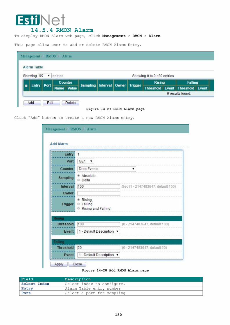
150
14.5.4 RMON Alarm To display RMON Alarm web page, click Management > RMON > Alarm
This page allow user to add or delete RMON Alarm Entry.
Figure 14-27 RMON Alarm page
Click “Add” button to create a new RMON Alarm entry.
Figure 14-28 Add RMON Alarm page
Field Description
Select Index Select index to configure.
Entry Alarm Table entry number.
Port Select a port for sampling

151
Counter Select an variable for sampling
Drop Events: Total number of events received in which
the packets were dropped.
Received Bytes (Octets): Number of bytes received
Received Packets: Number of packets.
Broadcast Packets Received: Broadcast packets.
Multicast Packets Received: Multicast packets.
CRC & Align Errors: CRC alignment error.
Undersize Packets: Number of undersized packets.
Oversize Packets: Number of oversized packets.
Fragments: Total number of packet fragment.
Jabbers: Total number of packet jabber.
Collisions: Collision.
Frames of 64 Bytes: Number of packets size 64 octets.
Frames of 65 Bytes to 127 Bytes: Number of packets
size 65 to 127 octets.
Frames of 128 Bytes to 255 Bytes: Number of packets
size 128 to 255 octets.
Frames of 256 Bytes to 511 Bytes: Number of packets
size 256 to 511 octets.
Frames of 512 Bytes to 1023 Bytes: Number of packets
size 512 to 1023 octets.
Frames of 1024 Bytes to 1518 Bytes: Number of packets
size 1024 to 1518 octets.
Sampling Select type for sampling
Absolute—the selected variable value is compared
directly with the thresholds at the end of the
sampling interval.
Delta—the selected variable value of the last sample
is subtracted from the current value and the
difference is compared with the thresholds.
Interval Input sample interval
Owner Owner of the Alarm.
Trigger Rising: Trigger on firing rising event.
Falling: Trigger on firing falling event
Rising and Falling: Trigger on both rising and falling
events.
Rising
Rising Threshold Threshold for firing rising event.
Falling Threshold Threshold for firing falling event.
Falling
Rising Event Index of rising event when alarm fired.
Falling Event Index of falling event when alarm fired.
Table 14-17 RMON Alarm fields


