50
ET ISO 10137 (2007) (English): Bases for design of structures - Serviceability of buildings and walkways against vibrations

Federal DemocraticRepublic of Ethiopia
≠ EDICT OF GOVERNMENT ±In order to promote public education and public safety, equal justice for all, a better informed citizenry, the rule of law, world trade and world peace, this legal document is hereby made available on a noncommercial basis, as it is the right of all humans to know and speak the laws that govern them.
ET ISO 10137 (2007) (English): Basesfor design of structures -Serviceability of buildings and walkwaysagainst vibrations


©ESA
(Identical with ISO 10137:2007)

This Ethiopian Standard has been prepared under the direction of the Technical Committee for Building structures and elements of building (TC 42) and published by the Ethiopian Standards Agency (ESA). The standard is identical with ISO
published by ( ). For the purpose of this Ethiopian Standard , the adopted text shall be modified as follows. The phrase “International Standard” shall be read as “Ethiopian Standard”; and A full stop (.) shall substitute comma (,) as decimal marker.
ISO 10137:20 (E)
1
Bases for design of structures �— Serviceability of buildings and walkways against vibrations
1 Scope
This International Standard gives recommendations on the evaluation of serviceability against vibrations of buildings, and walkways within buildings or connecting them or outside of buildings.
It covers three recipients of vibrations:
a) human occupancy in buildings and on walkways;
b) the contents of the building;
c) the structure of the building.
It does not include bridges that carry vehicular traffic, even in conjunction with pedestrian traffic, nor the design of foundations or supporting structures of machinery.
For the purposes of this International Standard, it is assumed that the building structure responds linearly to the applied loads. This means that the structure does not yield or fail, nor is it subject to significant non-linear effects.
2 Normative references
The following referenced documents are indispensable for the application of this document. For dated references, only the edition cited applies. For undated references, the latest edition of the referenced document (including any amendments) applies.
ISO 2041, Mechanical vibration, shock and condition monitoring �— Vocabulary
ISO 2372, Mechanical vibration of machines with operating speeds from 10 to 200 rev/s �— Basis for specifying evaluation standards
ISO 2394:1998, General principles on reliability for structures
ISO 2631-1:1997, Mechanical vibration and shock �— Evaluation of human exposure to whole-body vibration �— Part 1: General requirements
ISO 2631-2:2003, Mechanical vibration and shock �— Evaluation of human exposure to whole-body vibration �— Part 2: Vibration in buildings (1 Hz to 80 Hz)
ISO 3010:2001, Basis for design of structures �— Seismic actions on structures
ISO 3898, Bases for design of structures �— Notations �— General symbols
ISO 4354, Wind actions on structures
ISO 4866:1990, Mechanical vibration and shock �— Vibration of buildings �— Guidelines for the measurement of vibrations and evaluation of their effects on buildings

ISO 10137:20 (E)
2
ISO 6897, Guidelines for the evaluation of the response of occupants of fixed structures, especially buildings and off-shore structures, to low-frequency horizontal motion (0,063 to 1 Hz)
ISO 8041, Human response to vibration �— Measuring instrumentation
ISO 8569, Mechanical vibration and shock �— Measurement and evaluation of shock and vibration effects on sensitive equipment in buildings
ISO 8930, General principles on reliability for structures �— List of equivalent terms
ISO/TS 10811-1, Mechanical vibration and shock �— Vibration and shock in buildings with sensitive equipment �— Part 1: Measurement and evaluation
ISO/TS 10811-2, Mechanical vibration and shock �— Vibration and shock in buildings with sensitive equipment �— Part 2: Classification
ISO 10816 (all parts), Mechanical vibration �— Evaluation of machine vibration by measurements on non-rotating parts
ISO 14837-1, Mechanical vibration �— Ground-borne noise and vibration arising from rail systems �— Part 1: General Guidance
3 Terms and definitions
For the purposes of this document, the terms and definitions given in ISO 2041 and ISO 8930 and the following apply.
NOTE See also ISO 3898 and ISO 2394.
3.1 amplification increase of vibration amplitudes relative to a reference amplitude
3.2 attenuation loss of vibration energy along a transmission path
3.3 broadband spectrum spectrum with the vibration distributed over broad frequency bands (e.g. octave-band spectrum, one-third-octave band spectrum)
3.4 damping dissipation of energy in a vibrating system
3.5 dynamic actions actions varying so quickly that they give rise to vibrations
3.6 dynamic forces forces varying so quickly that they give rise to vibrations
3.7 Fourier transformation mathematical procedure that transforms a time record into a complex frequency spectrum (Fourier spectrum) without loss of information

ISO 10137:20 (E)
3
3.8 frequency components centre frequencies of narrow bands in which the energy of a spectrum is concentrated
3.9 frequency response function frequency spectrum function of the output signal divided by the frequency spectrum function of the input signal
NOTE The frequency response is usually given graphically by curves showing the amplitude relationship and, where applicable, phase shift or phase angle, as a function of frequency. Alternatively, it is the Fourier transformation of the response of the structure to an impulse.
3.10 geometric spreading decay of vibration amplitudes with increasing distance from the source as the energy is spread over a larger volume
3.11 impulsive source source which gives a dynamic action of a short duration compared with the natural period of the structure under consideration
3.12 mode of vibration deflected shape at a particular natural frequency of a system undergoing free vibration
3.13 narrow-band spectrum spectrum with the vibration concentrated in narrow frequency bands
3.14 natural frequency frequency at which a mode of vibration will oscillate under free vibrations
3.15 octave-band spectrum spectrum determined by means of a filter cutting off frequencies outside a band, where the maximum frequency in each band is equal to the minimum frequency multiplied by 2
3.16 receiver person, structure or contents of a building subjected to vibrations
3.17 response spectrum maximum responses of a series of single-degree-of-freedom systems subjected to a given dynamic base motion, plotted as a function of natural frequencies for specific values of damping
3.18 shock dynamic action with a duration that is short compared to the natural period of the receiver
3.19 shock spectrum response spectrum for a shock motion
3.20 source origin of the vibration
ISO 10137:20 (E)
4
3.21 spectrum plot of a time-varying function transformed into the frequency domain
3.22 sustained vibration vibration having a duration of many periods
3.23 third-octave-band spectrum spectrum determined by means of a filter cutting off frequencies outside a band, where the maximum frequency in each band is equal to the minimum frequency multiplied by 2
3.24 transfer function for a system, a mathematical relation in the frequency domain between the output and the input to the system
3.25 transmission path path from the source to the receiver
3.26 unbalanced force force originating from unbalance of a rotating mass at the source
3.27 walkway footbridge pedestrian bridge structure carrying pedestrian traffic, but no motorized vehicles, within buildings, between buildings or outside of buildings
4 Description of the vibration problem
4.1 General remarks
Vibrations arise from the interaction between time-varying disturbances and the inertia properties of the affected medium. The disturbance can be in the form of forces or displacement functions; the affected media can be solids, liquids or gases. The vibration process can be described mathematically by employing Newton�’s laws of motion and incorporating the appropriate deformational properties of the affected medium.
The evaluation of vibrations in buildings and walkways has to take account of the characteristics of the vibration source, the transmission path and the receiver. The vibration source produces the dynamic forces or actions. The medium or the structure between the source and receiver constitutes the transmission path, and the resulting vibrations at the receiver are then subject to the applicable criteria of the specified serviceability limit state. The dynamic actions are, in general, a function of time and space and are described in Clause 5. Clause 6 deals with methods of response analysis and Clause 7 with applicable vibration criteria. The values of actions, effects and criteria presented in this International Standard are some of the other representative values given in ISO 2394:1998, 6.2.1. Whenever data are available, the method of partial coefficients, in accordance with ISO 2394, should be employed for verification of the serviceability.
4.2 Vibration source
The vibration source can be inside or outside the building.
ISO 10137:20 (E)
5
4.2.1 Vibration sources inside a building
Vibration sources inside a building include:
human excitation;
rotating and reciprocating machinery;
impact machinery (punches, presses, etc.);
moving machinery (trolleys, lift trucks, elevators, conveyors, overhead cranes, etc.);
construction or demolition activity in other parts of the building.
4.2.2 Vibration sources outside a building
Vibration sources outside a building can occur on the ground surface, underground, in the air, or in water, such as:
construction, mining or quarry blasting;
construction activity (pile driving, compaction, excavation, etc.);
road and rail traffic;
sonic boom or air blast;
fluid flow (wind or water);
punching presses or other machinery in nearby buildings;
impact of ships on nearby wharves;
rock bursts,
4.3 Transmission path
The transmission path has the effect of modifying the vibrations from the source to the receiver due to discontinuities, attenuation due to geometric spreading and material damping, and possible amplification or attenuation in certain frequency ranges.
4.4 Receiver
The receiver of the vibrations is the object or person for which the vibration effects are to be assessed. This can encompass the building structure (or components such as beams, slabs, walls, windows, etc.), the contents of the building (instruments, machines, etc.), or the human occupants of the building.
5 Dynamic actions
5.1 General remarks
The dynamic actions are the forces, displacements, velocities, accelerations or energy associated with the vibration source. In many cases, the dynamic actions cannot be predicted in a deterministic sense, in which case it may be appropriate to consider the actions as random.
ISO 10137:20 (E)
6
5.2 Machinery
5.2.1 Rotating machinery
Values for the unbalanced forces of rotating machinery should be supplied by the manufacturers. In the absence of such data, the maximum acceptable unbalanced forces for the respective category of machines can be taken from ISO 2372 for electrical machines, or ISO 10816 for large rotating machines, or from other applicable standards. The forces produced by unbalance change with the flexibility of support conditions, and whether the operating frequency is above or below the mounted resonance frequency of the machine. There is also a trend for unbalanced forces to increase as machines age, and allowance for this effect should be made. Machines and their components can induce large forces during breakdowns or rapid stoppages. These actions should be considered in assessing the serviceability limit state. Unbalanced forces from attachments to machines (transmissions, rotors, etc.) also need to be considered.
Start-up and run-down conditions shall be considered when the operating frequency is above any of the resonance frequencies of the mounted machine or any of the support elements or structures.
5.2.2 Reciprocating machinery
The actions of reciprocating machinery depend on the type and construction of the machine, the operating conditions such as rotational speed and load, mounting details, and the age and state of maintenance of the machine. The quantitative descriptions of actions should be available from the manufacturer, but can be measured or calculated in the form of time histories of forces or displacement functions (accelerations, velocities or displacements) or the spectra of these quantities.
5.2.3 Impacting machinery
This includes machines such as forge hammers, stamping presses and pile drivers. The forces generated are usually very large. The action can be described in terms of a displacement (or velocity or acceleration)-time history or energy per impact. These values should be provided by the manufacturer but can be derived by measurements or calculations.
5.2.4 Other machinery
Certain machinery (e.g. grinding mills) combine random-type excitations with other types of excitation, such as rotational or, possibly, impact.
5.3 Vehicular traffic (road and rail)
5.3.1 General remarks
Motor vehicles with pneumatic tyres and trains on rails are two major sources of vibrations. The action can be described by force-time functions, displacement functions, or by a source spectrum. Stationary point sources, line sources, area sources, or moving sources shall be considered as applicable. Because of the complexity of the problem, empirical methods based upon measurements are often required. These may be combined with analytical and numerical modelling, as appropriate.
5.3.2 Motor vehicles
Vibrations induced by motor vehicles depend on suspension characteristics, mass, speed, traffic density, type and roughness of the road (including discrete irregularities), and subgrade properties.
The effects of these factors are interrelated and cannot be described by simple formulae.

ISO 10137:20 (E)
7
5.3.3 Railway trains
Major factors that affect vibrations induced by railway trains are the following;
type of train (high speed, ordinary, subway, etc.);
weight;
speed;
type of track, or type of rail (continuous rails, jointed rails, surface irregularities, etc.);
ballast, subgrade and general soil conditions.
The effects of these factors are interrelated and cannot be described by simple formulae. General guidance on vibrations from trains is given in ISO 14837-1.
5.4 Impulsive sources
5.4.1 General remarks
The characteristics of the vibration source are described in terms of the time variation of force, pressure or displacement function (including velocity and acceleration). Approximate descriptions include the following:
peak values and duration for impulsive sources;
root-mean-square (r.m.s.), or peak and frequency content for sustained vibrations;
statistical descriptions, such as r.m.s., third-octave, octave and narrow-band spectra;
response (or shock) spectra.
When r.m.s. quantities are used, attention should be paid to the method of averaging. It is assumed that there are only a few occurrences per day and that the total duration of the activity is of a temporary nature (e.g. construction). It is recommended to use a 1 s averaging time as given in 6.3.1 of ISO 2631-1:1997.
5.4.2 Impulsive sources in the ground
The main characteristic of impulsive sources, such as construction blasting, surface mining and pile driving is the energy released into the ground. The ground motion parameters at a given distance from the source can be obtained by empirical methods based on measurements, resulting in ground motion bounds and estimated response spectra.
Rock bursts, caused by collapse of underground cavities or localized re-arrangement of rock as a result of previous or ongoing mining activity, share many characteristics with earthquakes, albeit on a smaller scale. The ground motion characteristics at a building site can be described by peak values, time series and/or response spectra. These characteristics will vary with the geology and mining history at or near the building site. Methods of characterizing ground motions from rock bursts for the serviceability limit state can be found in ISO 3010.
5.4.3 Controlled intermittent and impulsive sources within a structure
Vibrations can be induced by controlled demolition operations and also by particular production processes which are not regular in time and intensity. These sources include the following:
use of heavy equipment (vehicles, vibratory rollers or breakers, wrecking tools, etc.);
controlled blasting within the structure;
falling of heavy objects.
ISO 10137:20 (E)
8
Cranes and lifts (elevators) can also induce impulsive forces during starting and stopping operations.
NOTE Accidental explosions or other types of accident which produce vibrations are not considered in this International Standard.
5.4.4 Airborne or waterborne impulsive sources
For explosive charges, the action is described in terms of the energy release or the overpressure-time variation. Sonic boom resulting from supersonic aircraft can be described in the form of pressure-time variations.
5.5 Human activity
5.5.1 Repetitive coordinated activities over a fixed area
For many repetitive coordinated human activities, the dynamic action is distributed more or less uniformly over a major portion of the structure. The active participants do not change their position, or the entire group of people moves so as to maintain a more or less uniform loading. This includes gymnastic exercises, dancing, coordinated jumping, running of a group of people, spectator action in halls or stadiums, or similar activities. The actions can be described by force-time histories or their spectral components.
5.5.2 Persons traversing structures
The dynamic actions of one or more persons can be presented as force-time histories or as their corresponding frequency components. This action varies with time and position as the person or persons traverse the supporting structure.
NOTE Special attention needs to be paid to avoid resonance effects in walkways with low horizontal and vertical natural frequencies. Some guidance is given in Annex A and Annex C.
5.5.3 Single pulses
Single pulses result from
persons jumping off objects,
persons jumping off steps on staircases or in floors,
accidental or deliberate dropping of objects onto floors, or
a single coordinated action, such as spectators jumping to their feet (for example at a sports event).
The action can be described in terms of force-time variations (or their Fourier transformation) or the impulse of the event.
NOTE Some descriptions of dynamic actions from human activities are given in Annex A.
5.6 Wind
The actions induced in structures by wind are specified in ISO 4354.
5.7 Earthquakes
The actions induced in structures by earthquakes are specified in ISO 3010.
ISO 10137:20 (E)
9
6 Evaluation of response
6.1 General remarks
The analysis of response requires a calculation model that incorporates the characteristics of the source and of the transmission path and which is then solved for the vibration response at the receiver. The type and complexity of the calculation model depends on the dynamic behaviour it must represent and by the accuracy required in the prediction of the vibration response. The simplifying assumptions employed in establishing and solving the calculation model shall be noted. The analysis may concern existing structures or may be a part of the design of new structures.
Vibrations in existing building structures should be evaluated by measurements, whenever possible, in order to complete and to check eventual calculations.
Approximate methods for predicting vibrations may be employed where
a) the approximating assumptions correspond closely to known reality, or
b) the overall effect has been verified by field experience and/or more refined calculations.
6.2 Methods of analysis
6.2.1 General remarks
Vibration problems can be classified in many ways, for example by amplitude, duration and frequency content. The analysis required is, in turn, dictated by the type of vibration source and the transmission path. If the dynamic actions are random, it may be appropriate to use random vibration theory.
Two broad classes of vibration problems can be identified:
Class A: the actions of the vibration source change in time and space.
Class B: the actions of the vibration source change in time but either are, or can be considered to be, stationary in space.
NOTE Examples of Class A: a vehicle moving along a street, a person walking across a floor; examples of Class B: vibrations from a mounted piece of machinery, people jumping in unison on a floor; examples of empirical methods: prediction of blasting vibrations, prediction of traffic vibrations.
Empirical methods are employed when the complete analytical solution of a problem may not be practical. Empirical methods can be used when they have been derived from a large number of experimental or theoretical results and where bounds of applicability have been established. When empirical methods and criteria are used for problems other than those for which they were derived, the applicability to the new situation needs to be verified.
The exact characteristics of the vibration source, transmission path and receiver may not always be well defined. This is particularly so when humans are both the vibration source and receivers, and when the very presence of humans on the structure may change its dynamic properties, as is the case for crowd loading on assembly structures. Similar uncertainties may exist in other problems involving vibrations. Therefore, some form of reliability analysis may need to be carried out (ISO 2394).
6.2.2 Actions that vary with time and space
When the action varies both in time and space, vibration problems become very difficult to solve analytically. For this reason, suitable simplifications are often sought in order to eliminate or uncouple the space variable. The complexity of these problems is one reason why many of them have been treated by empirical methods, or by extensive use of measurements on similar existing structures.

ISO 10137:20 (E)
10
6.2.3 Actions that vary with time
When the vibration source does not move in space, many analysis methods can be employed to solve vibration problems. Common solution techniques involve the derivation of an equivalent single-degree-of-freedom system or modal analysis for both continuous and discrete systems.
6.3 Evaluation of vibration levels by calculation
6.3.1 General remarks
For the determination of the vibration levels at the receiver, in general, a two-step procedure is necessary:
a) mathematical modelling of the dynamic characteristics of the structure, foundation or component;
b) calculation of the response at the receiver, taking account of the vibration source characteristics.
The mathematical model can either be based on continuous mass distribution or discrete mass distribution (multi-degree-of-freedom system).
NOTE Some examples of mathematical modelling and response calculations are given in Annex B.
6.3.2 Damping for the serviceability limit state
Damping is an important property that governs the response at or near resonances. Damping depends on the materials employed, construction details, and the presence of non-structural components, such as floor coverings, ceilings, mechanical equipment and partitions. Also, people will add to the overall level of damping. In general, damping cannot be calculated or predicted reliably, and experience with similar types of construction provides a likely source of appropriate damping data. Whenever possible, the damping data should be established by measurements. It should be noted that damping in buildings and building components is often amplitude dependent, and this shall be taken into account when measured data is employed for calculating dynamic response at various amplitudes. A number of damping mechanisms can be identified (e.g. viscous, frictional, hysteretic and a combination thereof), and are modelled mathematically in different ways. Care shall be taken in designating the damping mechanism and the limits associated with it.
NOTE Specific examples of damping values can be found in Annex B. Values of damping for various serviceability limit states need to be chosen to reflect, among other things, the level of response (e.g. earthquake versus traffic vibrations; cracked versus uncracked state for concrete).
6.3.3 Vibrations propagating in continuous media
Continuous media (or continua) are those physical systems for which the wavelength of the action is substantially shorter than the physical dimensions of the medium. For such cases, when calculating transmission of vibrations one needs to employ principles of wave propagation theory.
When calculating vibrations propagating in continua one needs to consider the following:
a) coupling effects at the source;
b) material properties of transmitting medium:
1) mass (density),
2) degree of saturation,
3) stiffness,
4) damping;

ISO 10137:20 (E)
11
c) geometric spreading of transmitting medium:
1) various forms of layering,
2) discontinuities and shielding,
3) geometric attenuation with distance from the source;
d) effects of interaction of the structure with soil or with a fluid;
e) transmission to the receiver within the building.
Layering and changes in geometry along the propagation path can lead to local amplification or attenuation in selected frequency ranges. For soils, the degree of compaction, saturation (e.g. location of the water table) and internal friction of the materials affect the attenuation characteristics of vibration with distance. In general, these situations are too complicated to be treated quantitatively; consequently they are often assessed by empirical methods.
The transmission properties shall be determined analytically or experimentally as functions of frequency (i.e. frequency response functions, transfer functions) or as functions of time (i.e. impulse response functions). Analytical methods shall be verified for their applicability to the given situation, and the results checked subsequently. Approximate or empirical formulations for the transmission function may be used where their applicability to the given situation has been substantiated by appropriate theoretical or experimental methods. In addition to transmission properties of the ground, possible changes in physical characteristics, such as densification, settlement, liquefaction and formation of slides, need to be considered. These are generally associated with vibrations of large amplitude or of long duration.
Pressure pulses and total impulse from underwater detonation of explosives along the line of sight can be calculated from charge/distance relationships. Rock or soil cover and air bubble curtains result in substantial reductions of peak pressure, but they lengthen the pulse. Reflections from solid boundaries and the water surface, and diffraction around obstacles in the line of sight between the source and receiver shall be considered.
6.3.4 Vibrations of discrete media
Many structures can realistically be modelled mathematically by discrete masses, stiffnesses and energy-dissipating devices. This permits the derivation of equivalent single-degree-of-freedom analogues or the consideration of normal modes of vibration, for which many solution methods are available. Whether a component can be discretized will depend on the particular application, however. For example, the response of a floor slab subjected to persons jumping on it may be carried out by the (discretized) approach of superposition of normal modes, whereas the same floor needs to be treated by a continuum approach (using wave propagation techniques) when high-frequency effects, such as structure-borne sound or impact response, are to be assessed.
6.4 Evaluation of vibration levels by measurement
6.4.1 General remarks
When the vibration levels in existing buildings are to be assessed by measurements, the measurement procedures, instrumentation and evaluation of results shall be carried out according to the following recommendations, and in accordance with ISO 8041.
6.4.2 Quantities to be measured
The vibration parameters measured and evaluated include displacements, velocity, acceleration and sometimes strain, all in conjunction with frequencies. The choice of measured parameters depends on the method of analysis used and the appropriate vibration criteria. Although each quantity of acceleration, velocity or displacement can be derived from one another by integration or differentiation, it is generally preferable to
ISO 10137:20 (E)
12
measure the desired quantity directly or, alternatively, to integrate. Differentiation is usually not recommended for other than harmonic signals because of possible numerical inaccuracies. Sufficient measurement time has to be employed in order to achieve adequate statistical reliability.
6.4.3 Measuring apparatus and range of parameters
The measuring apparatus should be selected by consideration of the vibration parameter to be measured and the expected range of the parameter.
NOTE 1 Commonly encountered ranges of measured quantities of building vibrations are the following:
frequency: 0,15 Hz to 100 Hz, except that for measuring impulsive responses and for buildings on rock it may be higher than 100 Hz;
accelerations: 10 3 m/s2 to 10 m/s2;
velocities: 10 5 m/s to 10 1 m/s; for measurements involving micro-electronic, optical and similar technologies (nano-technology), lower limits may apply;
displacements: 10 7 m to 10 2 m.
NOTE 2 A basic vibration measuring set can consist of measuring sensors, signal-conditioning circuitry, and a recording or monitoring instrument.
NOTE 3 For complex vibrations, either analogue or digital recording can be employed; direct analysis instruments can also be used.
6.4.4 Arrangement of measurement points
6.4.4.1 Measurements of vibrations acting on buildings
The arrangement of measurement points and directions depends on the type of structure and on the evaluation method to be used, and shall be specified in the testing programme.
The measurement locations and directions should be chosen to be compatible with the geometry of the structure and the excitation source. This will usually result in the use of rectangular coordinates (x and y, horizontal; z, vertical). However, an arrangement of sensors along cylindrical or other special coordinate systems may be appropriate for special situations.
For particular cases, the following should be observed.
a) When the vibration parameters to be measured are used to determine horizontal actions on the existing building, measuring points should be located on or near the walls; in multi-storey buildings, measuring points at three or more levels should be used.
b) When an evaluation of the effect of induced kinematic forces on a building to be constructed is based on vibration measurements, the measuring point should be located on the ground at the planned location of the building. More reliable results will be obtained if the measuring point is located at the bottom of an excavation at the projected foundation level.
c) To evaluate the vibration severity using scales of dynamic effects, the measuring point should be placed on the foundation or on a load-bearing wall at ground level on the side facing the source of vibrations.
6.4.4.2 Measurement of vibration effects on machinery and equipment in buildings
For measuring these vibration effects, one or more measuring points shall be located either on the machine base plate or the supporting structure of equipment, at a location where the most intense vibrations are expected to occur.

ISO 10137:20 (E)
13
6.4.4.3 Measurement of vibration effects on people in buildings
Measurement points shall be located in a place where people are likely to sense the vibrations. Vibrations shall be measured in the directions which are likely to affect the people unfavourably. In cases of uncertainty, vibrations in all three orthogonal directions shall be measured.
6.4.5 Vibration measurement analysis and results
Measurement conditions shall be specified in the testing programme.
For complex vibrations of long duration, the measured parameter shall be recorded on suitable analogue or digital equipment and then analysed by appropriate methods. Limiting values of vibration measurements at specified measurement points shall be compared with the applicable serviceability criteria.
6.4.6 Measurement report
A report shall be prepared covering the following:
purpose of measurement;
formal basis of measurement (e.g. pertinent standard);
description and location of vibration source;
instruments used (type, number, calibration details, measuring ranges);
method of attachment of transducers;
recording details (record length, sampling rate, filter settings, amplification, etc.);
building description including its technical condition;
arrangement of measuring points with pertinent distances and dimensions;
associated conditions and events (atmospheric conditions, other disturbances, etc.);
names of members of the measurement team;
summary of readings or results.
7 Vibration criteria for the serviceability limit state
7.1 General remarks
The vibration criteria shall correspond to the serviceability limit state that is specified for the receiver.
The designer shall decide on the serviceability criterion and its variability. The variability in the limit state is usually contained in the criteria for the receiver. A certain probability that the serviceability criterion will be exceeded has to be accepted. There are cases, however, when the serviceability criterion should not be exceeded, especially when a result is not reversible (e.g. cracking, settlement); a lower probability of exceedance should then be chosen. Guidance is given in ISO 2394. Another variability concerns the determination of the natural frequency of the affected structure or component.

ISO 10137:20 (E)
14
The criteria pertaining to this International Standard address three categories of receivers:
a) human occupants;
b) building contents;
c) building structures.
7.1.1 Criteria for human occupants
Criteria for human reaction to vibrations can be grouped into those pertaining to
�“sensitive�” occupancies, such as hospital operating rooms,
�“regular�” occupancies, such as offices and residential areas, and
�“active�” occupancies, such as assembly areas or places of heavy industrial work.
NOTE The latter includes floors in arenas, gymnasia and stadiums subjected to activities such as dancing, running, jumping and coordinated spectator movements.
7.1.2 Criteria for building contents
Criteria for contents of buildings shall include vibration levels that assure satisfactory functioning of sensitive instruments or certain manufacturing processes that are located within the building. Examples of such building contents are micro-balances, electron microscopes, photographic projections of integrated circuits, growing of crystals, laser interferometry techniques, nano-technology, etc.
7.1.3 Criteria for building structures
Criteria for building structures can correspond to a serviceability limit state which may include minor damage to structural or non-structural elements. This does not include overloading of the buildings or components which may result in excessive permanent deflection or collapse. The tolerable levels of vibration depend on the type of structure, age and importance (monumental or historic value, temporary shelter, etc.), state of repair, type and duration of vibrations, and loading history. Some examples of vibration criteria are given in Annex C.
NOTE The serviceability limit state for structures can include spalling of finishes (plaster, cladding), hairline or visible cracking of reinforced concrete or other materials, or maximum acceptable dynamic displacement.
7.2 Vibration criteria for human occupancies
7.2.1 General remarks
For people, the acceptable vibrations depend on the environment in which the vibrations occur. Some acceptable vibration levels are given in Annexes C and D. These vibration criteria may have to be adjusted further to suit particular circumstances.
NOTE Many factors influence the response of people to vibration in buildings. Direct effects include the frequencies, magnitude, duration, variability, form, directions of the vibration and intervals between vibration events, or exposure of the human subjects to the vibration. Indirect effects on the subjective response to an environment that includes vibrations are: audible noise and infrasound, visual cues, population type, familiarity with vibration, structural appearance, confidence in a building structure, height above ground, warning of events, activities engaged in, knowledge of the source of vibration, etc. In the interpretation of measured data relative to human sensitivity, attention is drawn to the importance of appropriate evaluation of peak factors and averaging times. See ISO 2631-1 and ISO 2631-2.
ISO 10137:20 (E)
15
The vibrations affecting human occupants may be divided into the following classes:
Class a: influences below human perception threshold;
Class b: basic threshold effects;
Class c: intrusion, alarm and fear (which may be associated with a range of adverse comments);
Class d: interference with activities;
Class e: possibility of injury or health risk.
In Class a, the criterion is based on interference when working with sensitive instruments where individuals come to realize that vibratory motion is present, although it is not directly perceived by any normal human sense, body function or component.
The criterion for the lower boundary of Class e is the requirement for provision of restraint harnesses or handholds to reduce the risk of injury to personnel as a result of low-frequency mechanical vibration or encroachment at higher frequencies into the �“exposure limit�” zones defined in ISO 2631-1 (see also ISO 6897).
Probable human response to vibration in Classes b, c and d is assessed in terms of the event category as
continuous,
impulsive, or
intermittent.
In general, the criteria for the restriction of vibration magnitudes for ordinary buildings are based on the minimum adverse comments of the population involved. Adjustment factors to the base criteria should be applied depending on the event category.
NOTE Guidance on assessment of probable human response to vibration in buildings in the frequency ranges 1 Hz to 80 Hz is given in Annex C, and in the range 0,063 Hz to 1 Hz in ISO 6897. Guidance for human response to wind-induced motions in buildings is given in Annex D. Various influences can combine to affect the subjective response of human beings to vibration. These include, among others, the presence of noise and linear and rotational vibration components in several axes acting simultaneously. Individual responses of affected persons can be modified by knowledge of the occurrence of events and by assurances of the safety of persons and property.
7.2.2 Requirements for walkways
Walkways shall be designed so that vibration amplitudes from applicable vibration sources do not unduly alarm potential users.
Different serviceability criteria need to be used for walkways within buildings or connecting them, than for those over roads, railways or waterways.
NOTE An example of vibration criteria for walkways is given in Annex C.
7.3 Vibration criteria for building contents
7.3.1 General remarks
The proper functioning and performance of many types of sensitive equipment or industrial process require a low vibration level in the building that houses them. Because of a large variety of such equipment and processes and their ever-changing technology, it is not possible to present any fixed levels of vibration amplitudes that would ensure satisfactory operation of all such equipment or processes.
ISO 10137:20 (E)
16
Two main cases can be distinguished:
a) design and construction of a new facility that is to satisfy a certain vibration criterion;
b) evaluation for suitability of an existing building or the location for housing specific instruments or types of process.
7.3.2 Vibration criteria for equipment and processes in buildings under design
The vibration criteria for satisfactory operation of equipment or a process should be provided by the manufacturer. In the absence of such information, generic criteria (e.g. Gordon (1991)) or experience with similar equipment or processes can be used, or a trial-and-error procedure followed. See ISO 8569, ISO/TS 10811-1 and ISO/TS 10811-2.
NOTE For sensitive equipment and processes, locations on slab-on-grade are, in general, preferable to those on suspended floors. In either case, vibration isolation of parts of the structure or the particular equipment can be necessary.
7.3.3 Evaluation of vibrations in existing buildings
For existing buildings, the vibration magnitudes at the location of equipment or processes can be measured (see ISO 8569) and compared with their applicable criteria. Where criteria are not available, experience with similar equipment or processes can be used, or a trial-and-error procedure followed.
7.4 Vibration criteria for building structures
7.4.1 General remarks
Aside from the human occupants and the contents of a building, the building structure itself has to withstand the imposed vibrations. The vibration level for the structure considered in this International Standard is one of serviceability in the form of visible cracking, spalling, minor settlement of foundations, or prescribed maximum vibration amplitudes of machinery supports or of machinery foundations. Such effects rarely compromise the short-term safety of the structure, but may lead to long-term deterioration (such as corrosion, water penetration and frost effects, unsightliness, settlement or fatigue) with possible safety or economic consequences.
The vibrations that a structure can sustain depend on the tensile, compressive or shear strength of the structural material with due allowance for fatigue or permissible deformations corresponding to the serviceability limit state. As far as possible, the effects from the vibrations shall be combined with the effects from other actions on the structure (loads, deformations, settlement, creep, etc.). Also, the general state of the building shall be taken into account (see ISO 4866).
The general principle outlined above is, in practice, either too lengthy or impossible to carry out because of the lack of relevant data or suitable methodology. Consequently, empirical methods are frequently adopted in the prediction or evaluation of vibration effects on buildings. The vibration levels shall be determined at critical or standardized locations, with due allowance for possible uncertainties in the source and receiver characteristics and the transmission path. Where the consequences of exceeding the recommended vibration limits are serious, monitored vibration tests (e.g. using small test blasts, shakers, etc.) can be carried out. The results can then be scaled to the specified criteria, taking account of appropriate amplitude and frequency scaling laws.
The evaluation of vibration effects shall include not only those structural parts in the immediate vicinity of the vibration source (e.g. foundations subjected to blasting), but also the main structural elements of the building (e.g. roofing, columns, walls, etc.) even if these elements are relatively distant from the vibration source. In this respect, the possibility of transmission of vibrations by air, by structural elements and through the soil shall be considered. As far as possible, the parameters to be used for establishing the criteria for existing structures should be based on measurements.
NOTE Examples of criteria are discussed in Annex C.
ISO 10137:20 (E)
17
7.4.2 Criteria for vibrations from impacts/impulses
These include vibrations from blasting, pile driving, soil compaction, demolition and other impacting construction activities. Widely accepted empirical vibration criteria, corresponding to measurements at the basement wall of a building, or in the adjacent soil, are employed in the form of peak displacements, velocities or accelerations. These values can be increased (or decreased) when special theoretical and experimental investigations are carried out to justify different levels. Such an investigation shall include consideration of type of structure, materials of construction, frequency characteristics of the ground motion, reliability of the determination of the response of particular portions of the structure, and consequences of exceeding the prescribed criteria. Guidance is given in ISO 4866.
7.4.3 Criteria for vibrations from other actions
Vibration levels from other actions (e.g. from traffic, machinery, wind and from those caused by people) shall satisfy the applicable serviceability limit state.
Special care should be taken where the operating frequency of one of the dominant harmonics lies within 30 % of the lower natural frequency of a structure or an affected component. For higher natural frequencies, a narrower range of frequencies to avoid may suffice.
7.4.4 Empirical criteria
Vibration criteria based on experience may be employed for cases where the scope and limits of applicability have been demonstrated.
7.4.5 Application of vibration criteria to measured vibrations
The measured vibrations can be compared to the appropriate vibration criteria, provided the data have been processed in a form compatible with the stated criteria. For random-type vibrations, the third-octave-band amplitudes may be employed.
8 Vibration control
Vibration control includes the monitoring of vibration effects at the source, in the transmission path, or at the receiver, in order to verify conformance with appropriate criteria.
When new vibration sources are introduced (e.g. construction blasting, conversion to exercise areas, etc.) and vibrations are likely to exceed the appropriate criteria at the receiver, vibration control by authorized competent personnel shall be provided to the receiver of the vibrations.
Vibration control can include one or more of the following:
periodic measurements of vibration effects and parameters (see 6.4);
selective checking of the intensity of events which produce vibrations (e.g. blasting);
installation of automatic recorders at selected points in the structure to control increase of vibrations.
Where the serviceability limit states for the building structure or its contents are likely to be exceeded, an examination of the pertinent buildings or components shall be undertaken before introducing the vibration source. This will permit a comparative evaluation of the effects of the vibration source on the receiver.

ISO 10137:20 (E)
18
Control points for vibration monitoring shall be selected where
a) the vibration effects can be expected to have their maximum values, and
b) the controlled effects may govern the behaviour of elements or the entire structure (this is particularly applicable to construction blasting).
Vibration control can be applied for existing buildings when they are subjected to a vibration source or for new construction during the design stage if large uncertainties exist for predicting vibration levels. For the latter, a remedial scheme of vibration isolation may be designed for future implementation, should adverse vibration levels actually materialize in the finished building.
9 Vibration mitigation
When the vibration levels in a building or structure are unsatisfactory for the intended or current use or occupancy, measures of vibration mitigation shall be employed.
The methods of vibration mitigation are based on employing principles of dynamics for the purpose of reducing the vibration effects at the receiver. This may involve methods of vibration insulation, modification of the building structure, changes or restriction of use and occupancy, change in vibration source characteristics, modification of transmission path, etc.
The effects of mitigation measures should be verified by measurements.
ISO 10137:2 (E)
19
Annex A (informative)
Dynamic actions
A.1 Actions from human motion
A.1.1 Repetitive coordinated activities
A.1.1.1 Dynamic forces
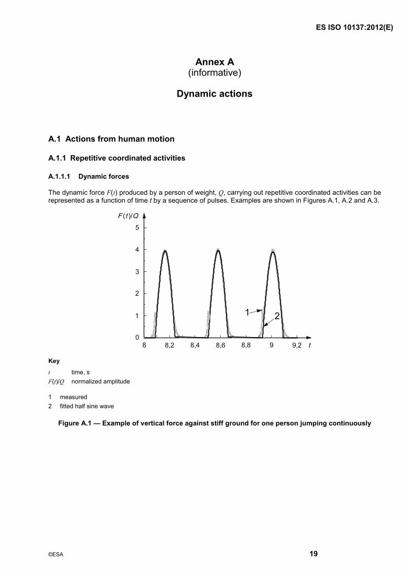
The dynamic force F(t) produced by a person of weight, Q, carrying out repetitive coordinated activities can be represented as a function of time t by a sequence of pulses. Examples are shown in Figures A.1, A.2 and A.3.
Key
t time, s F(t)/Q normalized amplitude
1 measured 2 fitted half sine wave
Figure A.1 �— Example of vertical force against stiff ground for one person jumping continuously

ISO 10137:20 (E)
20
Key
t time, s F(t)/Q normalized amplitude
Figure A.2 �— Example of vertical force against stiff ground for one walking step by one person
Key
t time, s F(t)/Q normalized amplitude
Figure A.3 �— Example of the force function for one person walking across a 3 m long instrumented platform
The action can be expressed in the frequency domain as a Fourier series:
,v ,v1
( ) 1 sin 2k
v n nn
F t Q nft in the vertical direction (A.1)
ISO 10137:20 (E)
21
and
,h ,h1
( ) 1 sin 2k
h n nn
F t Q nft in the horizontal direction (A.2)
where
n,v is a numerical coefficient corresponding to the nth harmonic, vertical direction;
n,h is a numerical coefficient corresponding to the nth harmonic, horizontal direction;
Q is the static load of the participating person;
f is the frequency component of repetitive loading; note that for assessing transverse horizontal vibrations, f is one-half the activity rate for the case of walking or running.
n,v is the phase angle of the nth harmonic, vertical direction;
n,h is the phase angle of the nth harmonic, horizontal direction;
n is the integer designating harmonics of the fundamental;
k is the number of harmonics that characterize the forcing function in the frequency range of interest.
Depending on the complexity of the time history of the load, the number of harmonics k needed to model adequately the time history of the load will vary.
A.1.1.2 Numerical coefficient
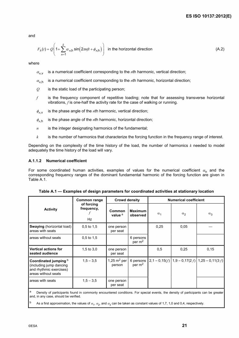
For some coordinated human activities, examples of values for the numerical coefficient n and the corresponding frequency ranges of the dominant fundamental harmonic of the forcing function are given in Table A.1.
Table A.1 �— Examples of design parameters for coordinated activities at stationary location
Crowd density Numerical coefficient
Activity
Common range of forcing frequency,
f
Hz
Common value a
Maximum observed 1 2 3
Swaying (horizontal load) areas with seats
0,5 to 1,5 one person per seat
�—
areas without seats 0,5 to 1,5 6 persons per m2
0,25 0,05
Vertical actions for seated audience
1,5 to 3,0 one person per seat
0,5 0,25 0,15
Coordinated jumping b (including jump dancing and rhythmic exercises) areas without seats
1,5 �– 3,5 1,25 m2 per person
6 persons per m2
1,25 �– 0,11(3 f )
areas with seats 1,5 �– 3,5 one person per seat
2,1 �– 0,15( f ) 1,9 �– 0,17(2 f )
a Density of participants found in commonly encountered conditions. For special events, the density of participants can be greater and, in any case, should be verified.
b As a first approximation, the values of 1, 2, and 3 can be taken as constant values of 1,7, 1,0 and 0,4, respectively.
ISO 10137:20 (E)
22
A.1.1.3 Dynamic actions of groups of participants
The dynamic action produced by groups of participants depends primarily on the weight of the participants, the maximum density of persons per unit floor area they occupy for which the activity can be carried out successfully, and on the degree of coordination of the participants. Examples of design values for crowd densities are presented in Table A.1.
In view of the fact that, in a group of people that is representative of the general population, some variability exists in both the frequency f, the phase angle n, and the numerical coefficient n, the dynamic response of the structure will be reduced compared to a group with perfect coordination. This reduced response can be accounted for in an approximate manner by applying a coordination factor C(N) to the forcing function:
F(t)N F(t) C(N) (A.3)
where N is the number of participants.
The coordination effect will depend on the complexity of the motion. For simple activities like hand-clapping, the coordination can be assumed to be unity; the more complex the activity becomes the smaller the coordination will be. For complex activities, the coordination will strongly depend on the individual rhythmic abilities of the group members. In the following, three typical scenarios are given to explain this dependency:
gymnasia: all individuals are well trained and are experienced to coordinate the motion in a group �– high coordination;
crowds viewing sports events: only some individuals are well trained, but most individuals are experienced to coordinate the motion in a group �– medium coordination;
crowds attending a pop concert: only some individuals are well trained and most individuals are not experienced to coordinate the motion in a group �– low coordination.
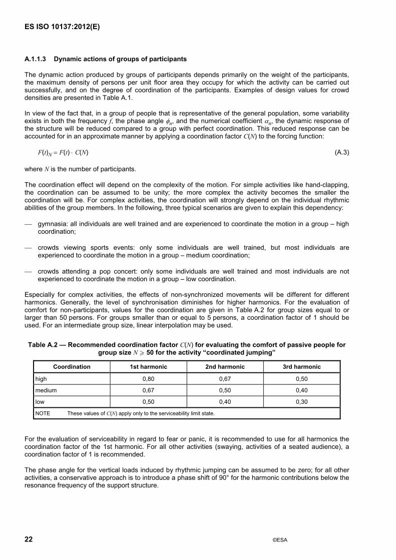
Especially for complex activities, the effects of non-synchronized movements will be different for different harmonics. Generally, the level of synchronisation diminishes for higher harmonics. For the evaluation of comfort for non-participants, values for the coordination are given in Table A.2 for group sizes equal to or larger than 50 persons. For groups smaller than or equal to 5 persons, a coordination factor of 1 should be used. For an intermediate group size, linear interpolation may be used.
Table A.2 �— Recommended coordination factor C(N) for evaluating the comfort of passive people for group size N W 50 for the activity �“coordinated jumping�”
Coordination 1st harmonic 2nd harmonic 3rd harmonic
high 0,80 0,67 0,50
medium 0,67 0,50 0,40
low 0,50 0,40 0,30
NOTE These values of C(N) apply only to the serviceability limit state.
For the evaluation of serviceability in regard to fear or panic, it is recommended to use for all harmonics the coordination factor of the 1st harmonic. For all other activities (swaying, activities of a seated audience), a coordination factor of 1 is recommended.
The phase angle for the vertical loads induced by rhythmic jumping can be assumed to be zero; for all other activities, a conservative approach is to introduce a phase shift of 90° for the harmonic contributions below the resonance frequency of the support structure.
ISO 10137:20 (E)
23
A.1.2 Walking or running
A.1.2.1 Dynamic forces
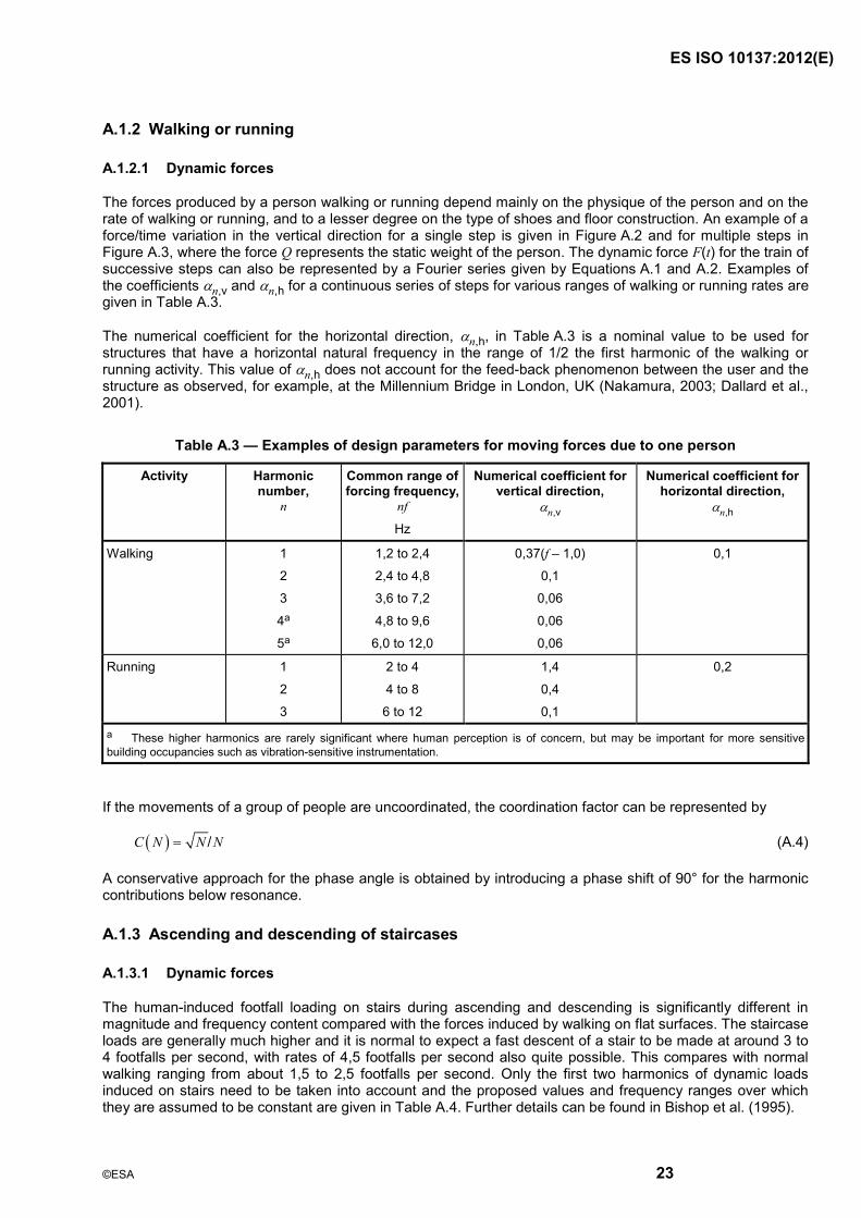
The forces produced by a person walking or running depend mainly on the physique of the person and on the rate of walking or running, and to a lesser degree on the type of shoes and floor construction. An example of a force/time variation in the vertical direction for a single step is given in Figure A.2 and for multiple steps in Figure A.3, where the force Q represents the static weight of the person. The dynamic force F(t) for the train of successive steps can also be represented by a Fourier series given by Equations A.1 and A.2. Examples of the coefficients n,v and n,h for a continuous series of steps for various ranges of walking or running rates are given in Table A.3.
The numerical coefficient for the horizontal direction, n,h, in Table A.3 is a nominal value to be used for structures that have a horizontal natural frequency in the range of 1/2 the first harmonic of the walking or running activity. This value of n,h does not account for the feed-back phenomenon between the user and the structure as observed, for example, at the Millennium Bridge in London, UK (Nakamura, 2003; Dallard et al., 2001).
Table A.3 �— Examples of design parameters for moving forces due to one person
Activity Harmonic number,
n
Common range of forcing frequency,
nf
Hz
Numerical coefficient for vertical direction,
n,v
Numerical coefficient forhorizontal direction,
n,h
Walking 1
2
3
4a
5a
1,2 to 2,4
2,4 to 4,8
3,6 to 7,2
4,8 to 9,6
6,0 to 12,0
0,37(f �– 1,0)
0,1
0,06
0,06
0,06
0,1
Running 1
2
3
2 to 4
4 to 8
6 to 12
1,4
0,4
0,1
0,2
a These higher harmonics are rarely significant where human perception is of concern, but may be important for more sensitive building occupancies such as vibration-sensitive instrumentation.
If the movements of a group of people are uncoordinated, the coordination factor can be represented by
/C N N N (A.4)
A conservative approach for the phase angle is obtained by introducing a phase shift of 90° for the harmonic contributions below resonance.
A.1.3 Ascending and descending of staircases
A.1.3.1 Dynamic forces
The human-induced footfall loading on stairs during ascending and descending is significantly different in magnitude and frequency content compared with the forces induced by walking on flat surfaces. The staircase loads are generally much higher and it is normal to expect a fast descent of a stair to be made at around 3 to 4 footfalls per second, with rates of 4,5 footfalls per second also quite possible. This compares with normal walking ranging from about 1,5 to 2,5 footfalls per second. Only the first two harmonics of dynamic loads induced on stairs need to be taken into account and the proposed values and frequency ranges over which they are assumed to be constant are given in Table A.4. Further details can be found in Bishop et al. (1995).

ISO 10137:20 (E)
24
Table A.4 �— Examples of design parameters for forces due to one person ascending or descending stairs
Activity Harmonic number,
n
Common range of forcing frequency,
nf,
Hz
Numerical coefficient for
vertical direction,n,v
Numerical coefficient for horizontal
direction, n,h
Ascending or descending stairs
1
2
1,2 to 4,5
2,4 to 9
1,1
0,22
Not available
A.1.4 Human impacts
A.1.4.1 Dynamic forces from human impacts
The idealized force pulse as a result of one person jumping from different heights is shown in Figure A.4. Examples of the ratio of peak forces Fmax to the weight of a person Q and duration td for different heights h are given in Table A.5.
Key
t time, s F(t)/Q normalized amplitude
1 Fmax/Q normalized peak force
2 td pulse duration, s
Figure A.4 �— Example of idealized force-time variation for a single impact by one person

ISO 10137:20 (E)
25
Table A.5 �— Examples of the ratio Fmax/Q and duration td for jumping by one person from various heights h
h (m) 0,20 0,40 0,60 0,80
Fmax / Q 8 10 12 14
td (s) 0,05 0,04 0,03 0,02
ISO 10137:20 (E)
26
Annex B (informative)
Examples of vibration analysis
B.1 Modelling of structure or component
Arriving at the appropriate choice of dynamic model requires skill and judgement. The model should be chosen with due regard to the complexity of the structure and the excitation, the degree of accuracy required, and the analysis facilities available. The force applied to the structure may also depend on the response of the supports of the vibration source. Examples of solution techniques, depending on the type of action, are given in Table B.1.
Some examples of specific mathematical modelling techniques are as follows.
a) Closed-form solutions of continuum mechanics. These are generally suitable for simple and regular geometric and material properties (e.g. uniform cantilever, simply supported beam, rods, elastic half-space). Normal modes of vibration and wave propagation methods are used.
b) Lumped parameter model. These are discretisations of mass and elastic properties that closely follow the physical system in modelling its physical properties (e.g. masses and stiffnesses lumped at each storey of a multi-storey building). Continuous structures and foundation media can also be modelled by lumped parameters, provided a sufficient number of discrete elements are chosen to represent adequately the actual physical systems. Normal modes of vibration can be obtained from an eigenvalue formulation.
c) Finite element and boundary element model. The continuum is represented by discrete elements whose size and dynamic properties are determined by the nature of the problem to be solved. Modal analysis and step-by-step integration or wave propagation procedures can be used.
d) Simplified dynamic model. Each mode of the vibrating structure with distributed mass can be represented by an equivalent single-degree-of-freedom model having identical natural frequency and identical deflection when subjected to the same dynamic loading.
e) Frequency response functions. These can be derived from the stiffness and mass properties of the structure.
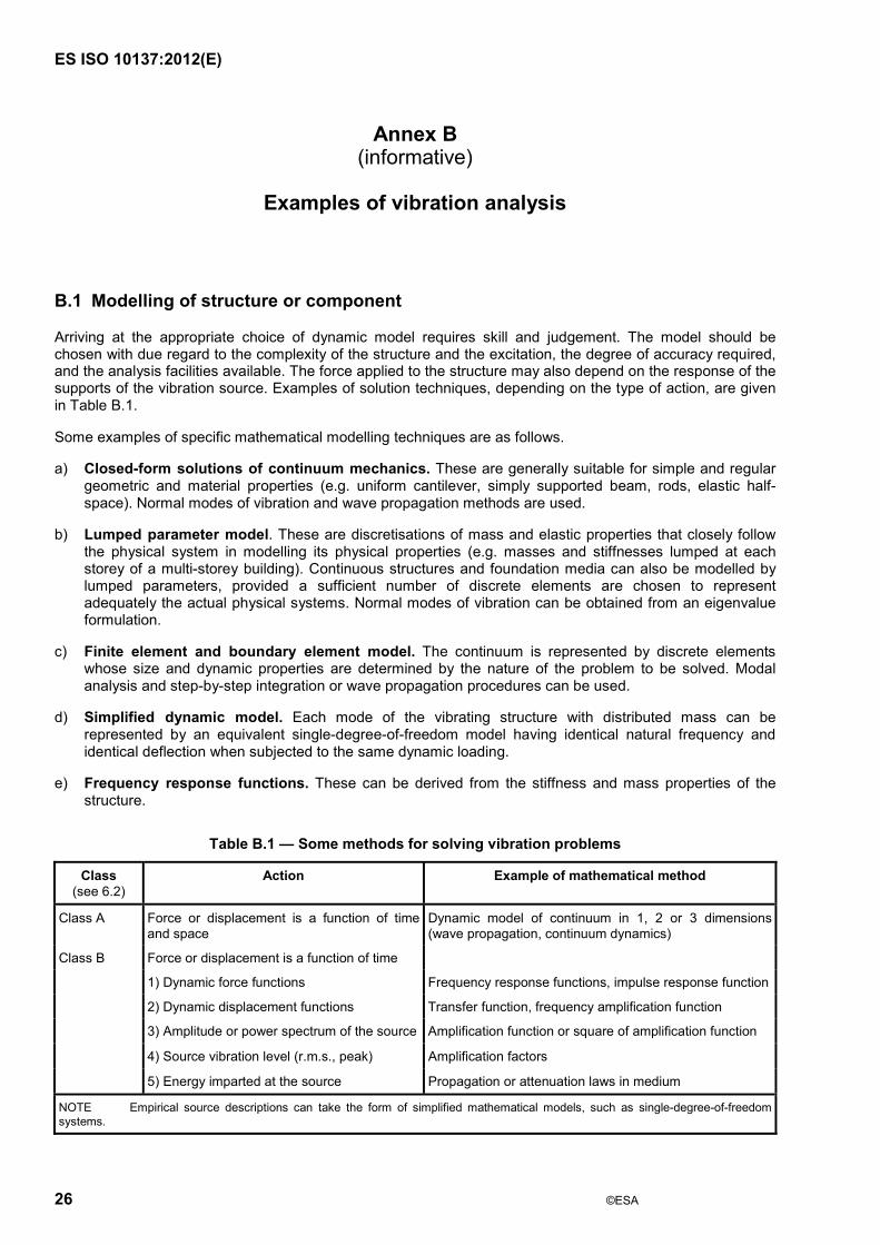
Table B.1 �— Some methods for solving vibration problems
Class (see 6.2)
Action Example of mathematical method
Class A Force or displacement is a function of time and space
Dynamic model of continuum in 1, 2 or 3 dimensions (wave propagation, continuum dynamics)
Force or displacement is a function of time
1) Dynamic force functions Frequency response functions, impulse response function
2) Dynamic displacement functions Transfer function, frequency amplification function
3) Amplitude or power spectrum of the source Amplification function or square of amplification function
4) Source vibration level (r.m.s., peak) Amplification factors
Class B
5) Energy imparted at the source Propagation or attenuation laws in medium
NOTE Empirical source descriptions can take the form of simplified mathematical models, such as single-degree-of-freedom systems.

ISO 10137:20 (E)
27
B.2 Determination of structural response by calculation
A number of methods for calculating the structural response are available. These include the following methods.
a) Closed-form solution of the equations of motion.
b) Step-by-step integration procedure for an oscillator subjected to a specific excitation. This can be performed in the time domain by the convolution integral (Duhamel integral) or numerical integration procedures, or in the frequency domain by Fourier or Laplace transform techniques.
c) Response spectrum or shock spectrum method. This gives the peak response for an oscillator of given frequency (or period) of vibration and damping when subjected to a given disturbance. For multi-mode response, an appropriate method of adding the individual modal responses has to be chosen.
d) Random vibration methods. These give the response of an oscillator to a disturbance having certain statistical properties. Both stationary and non-stationary procedures are available. Transfer functions or dynamic admittance properties of the structure are generally required.
e) Impulse response calculation. This gives the response of an oscillator whose natural period is large compared to the duration of the pulse. Peak initial velocity can be determined by this method.
f) Empirical procedures. These can provide satisfactory results for some classes of problems. Such procedures are derived either from experimental data or from approximations to the pertinent mathematical models. They can incorporate aspects of the actions and the criteria, but are often limited in their scope of applicability.
B.3 Vibration analysis of specific structures or elements
B.3.1 Entire building structure
B.3.1.1 Amplification of vibrations throughout a building
Where vibrations are determined at the basement wall or at the foundations, the amplifications inside the building to the location of the receiver need to be considered. Where detailed prediction of vibration effects is justified, the vibration levels may be calculated by step-by-step numerical methods, by response spectrum techniques or determined by measurements.
For steady-state vibrations, the amplifications from the source to receiver are given by the frequency response function. The frequency response function can be obtained by analysis or by experiment. For transient vibrations, the time variation of the vibrations can be found by numerical integration.
Since damping is an important parameter in the dynamic response of structures, care needs to be exercised in choosing values that are appropriate to the type of structure and the amplitude of response. Values of damping should be based on measurements, wherever possible. Some suggested damping ratios used for the calculation of response to wind, for example, are 0,01 for steel-frame buildings and 0,02 for concrete-frame buildings. Other bare structures may require lower values. See also ISO 4354.
B.3.2 Building components
B.3.2.1 Foundations
The dynamic behaviour of foundation elements or entire structures resting on soil, and the interaction between the structure and the soil, need to be considered in the evaluation of vibration problems that involve the ground as a transmission medium.

ISO 10137:20 (E)
28
B.3.2.2 Beams and floors
The response of a building component to persons walking or running depends on the structural characteristics and on the force produced by the person or persons. Perceptible and annoying floor vibrations have been observed mainly in floors with intermediate span lengths, i.e. from about 3 m to 20 m. For shorter spans, the damping and stiffness characteristics generally preclude vibrations at noticeable magnitudes, and for longer spans the total mass becomes large so that the floor response becomes small. Nevertheless, annoying vibrations can still be generated when resonance occurs between the steps and the floor modes. Vibrations can also be transmitted to adjacent floors or storeys, depending on the excitation intensity and the dynamic properties of the structure. Examples of dynamic actions produced by people are given in Annex A. Methods of analysis for design and assessment of floors are given in Allen et al. (1999), Murray et al. (1997), Wyatt (1989), and Ohlsson (1988).
B.3.2.2.1 Dynamic properties of floors
For the prediction of vibrations of beams and floors, the modes of vibration and the associated frequencies and damping values are required. Examples of damping values for some floors are given in Table B.2.
For purposes of calculating the dynamic response and for assessment against applicable serviceability criteria, floors commonly encountered in buildings can be categorized as
a) low-frequency floors with a fundamental natural frequency f0 less than approximately 8 to 10 Hz , and
b) high-frequency floors with f0 greater than approximately 8 to 10 Hz.
B.3.2.2.2 Floor response due to walking and running
Floor vibrations from walking or running can be calculated from the force variation and geometric and dynamic properties of the floor by the convolution or Duhamel integral. The action of more than one person needs to be considered if coordinated walking, running or marching to music or a regular beat, or other synchronized movements will occur. For well-coordinated groups, the total vibration effect is the sum of the individual contributions; this will yield an upper limit to the predicted vibration levels. For larger groups, a reduction factor C(N) can be applied as presented in Annex A. For persons traversing a floor, the limited duration of excitation should be considered in evaluating the response. An upper bound solution can be obtained by considering the excitation to be continuous.
For uncoordinated walking or running by a group of people, the forces on the floor can be estimated as outlined in Annex A with the aid of the coordination factor C(N) given by Equation A.3.
B.3.2.2.3 Evaluation of floor vibrations from coordinated activities
A number of persons walking, running or jumping in a coordinated manner, often accompanied by a musical beat, can excite a floor to substantial vibration levels. For uniformly distributed loading, the acceleration max at midspan of a beam-like structure can be determined from methods presented by Murray et al. (1997) and Wyatt (1989).
Examples of values of design parameters for various activities are given in Table A.1.
The addition of the contributions from the various harmonics of the excitation force should be considered in arriving at the total vibration amplitudes.

ISO 10137:20 ( )
29
Table B.2 �— Examples of damping values for the fundamental mode of floors in buildings
Damping ratio
% of critical Type of floor
Range of spans for damping ratios
given m Typical
range Extreme
range Values for preliminary design of bare floors
Steel joist/concrete slab simply supported 9 to 15 0,8 to 3,0 0,6 to 7,4 1,3
Steel joist/concrete slab, continuous slab construction across walls
4 to 8 1,0 to 5,0 0,8 to 8,6 1,5
Fully composite steel beams with shear connectors to concrete slab
6 to 20 1,5 to 5,0 0,5 to 8,0 1,8
Prestressed concrete, precast 2 to 15 0,8 to 3,0 0,5 to 6,5 1,3
Reinforced concrete, monolithic 5 to 15 1,0 to 3,0 0,6 to 5,0 1,5
Wood joist floors 2 to 9 1,5 to 4,0 1,0 to 5,5 2,0
NOTE Damping ratios depend on the type of construction, material, presence of non-structural elements, age, quality of construction, and amplitude and frequency of vibration. For concrete structures, the presence or absence of cracks is also significant. For any form of construction, the type of joint and the type of bearing employed play an important role in damping. For floors, the presence of some floor and ceiling finishes and partitions can increase the damping considerably.
When the critical point of vibration perception is not at the centre of a simply supported span of uniform mass and stiffness, as is assumed in the above calculation, then the limiting acceleration amax can be multiplied by
sin( x/L), for simply supported structures,
[6(x/L)2 4(x/L)3 + (x/L)4]/3, for cantilevers, or
0,5[1 cos(2 x/L)], for fixed-end structures,
where
x is the distance of vibration perception from support;
L is the span length.
Special attention needs to be paid to the prediction of vibration amplitudes for floors on flexible supports or for those having multi-span structural configurations. It is recommended that a full modal approach be taken or at least that approximate account be taken of the various flexibilities, as for example with a Rayleigh-Ritz method or the Southwell-Dunkerley approximation.
B.3.2.2.4 Floor response to single pulses
For cases where pulse loading needs to be considered, the response of a floor system to a single impulse can be calculated by
a) the Duhamel integral,
b) the Fourier transform,
c) impulse response approximation, or
d) other numerical methods.

ISO 10137:20 (E)
30
B.3.2.2.5 Approximate procedures for pulses
Approximate procedures for calculating the response to human impacts consist of applying to the equivalent modal mass of the floor an impulse equal to the area under the force/time curve for the impact under consideration. This is reasonably accurate for floors with frequencies above 1/(2td), where td pulse duration. Otherwise, a correction for the response of the floor system to pulses of various durations has to be applied.
Force/time variations for objects hitting a floor are not generally available. Approximate impact theories or, preferably, experimentally measured values should be employed for such predictions of vibration response of floors.
B.3.2.3 Walkways
Walkways, or bridges used mainly or entirely for pedestrian traffic, are subjected to excitation forces from persons walking, running or jumping, and also to the actions from wind and ground vibrations. Although walkways often can be considered analogous to a beam, the possibility of torsional vibrations also needs to be considered, either coupled or uncoupled from horizontal or vertical deflection components.
The vibration amplitudes resulting from one person or a few persons acting in unison may be calculated from principles of structural dynamics using the applicable actions. See Annex A for examples of forcing functions. For a simply supported beam structure, the acceleration produced may be calculated by the method outlined in B.3.2.2.3. For multi-span construction with continuity, appropriate changes in the stiffness and the equivalent modal mass are required.
For walkways with horizontal natural frequencies less than approximately 1,3 Hz, the effect of horizontal vibrations induced by walkers or runners needs to be considered. See, for example, Nakamura (2003). In the absence of more precise data, the values of damping for vertical vibrations given in Table B.3 can be used.
Table B.3 �— Examples of values of damping for vertical vibrations of walkways
Type of superstructure Damping ratio
% of critical
Steel with asphalt or epoxy surfacing
Composite steel/concrete
Prestressed and reinforced concrete
0,5
0,6
0,8
B.3.3 Propagation of vibrations in the ground
B.3.3.1 General remarks
The propagation of vibrations in the ground is a complex phenomenon, and from a practical viewpoint, only few cases can be solved by analytical treatment alone. Thus, empirical procedures are generally employed, usually in combination with analysis and measurement procedures.
In general, the vibrations with amplitude a emanating from a source having reference amplitude ao can be described by the product of a geometric attenuation term C and a material damping term D:
a ao C D (B.1)
The function C depends on the type of wave (shear waves, compressional waves, surface waves, etc.) and on the geometry of the source (point source, line source). The material damping term D may assume various forms of frequency and amplitude dependence.

ISO 10137:20 (E)
31
A class of propagation problems in a homogeneous half-space where the source can be considered stationary in space and the material properties are frequency- and amplitude-independent has the following characteristics:
C (ro/r)n (B.2)
D exp [ 2 (r ro)/ ] (B.3)
where
is the material damping ratio of the propagating medium;
r is the distance from the source;
is the wavelength of vibrations;
ro is the reference distance from the source.
For a point source of vertical forces at the surface of an elastic half-space:
n 0,5 for Rayleigh waves;
n 2 for body waves (compressional and shear) along the surface;
n 1 for body waves away from the vicinity of the surface.
For a line source of vertical forces at the surface of an elastic half-space:
n 0 for Rayleigh waves;
n 1,5 for body waves (compressional and shear) along the surface.
In practice, however, a homogeneous half-space with respect to wave propagation almost never exists, even in the absence of layering or a groundwater table. Possible exceptions may be certain rock formations or highly overconsolidated cohesive soils. Therefore, the above equations should be considered as averaging relations. Locally, however, considerable deviations may occur.
The material damping ratio decreases with decreasing amplitudes of vibration, is usually frequency dependent, and has to be determined experimentally.
B.3.3.2 Vibrations induced by vehicular traffic
Because of the many complexities in source and transmission, traffic-induced vibrations are usually treated by empirical methods. Such procedures generally incorporate the action as part of the vibration prediction model; these procedures have been developed in a number of countries. Since they were derived from experience, they tend to reflect the predominant conditions in that particular location, among them the traffic conditions, construction methods, soil conditions, etc. Thus, the methods may not be universally applicable.
B.3.3.3 Vibrations induced by trains
In principle, vibrations generated by trains can be treated by methods of transfer function and amplitude/distance relationships. In practice, however, this is not generally realizable and is still in the development stage. Consequently, empirical procedures are employed, together with measurement programmes for calibration of empirical constants.
ISO 10137:20 (E)
32
B.3.3.4 Vibrations from machine foundations
Machine foundations constitute part of the transmission path from the source (the operating machine) to the receiver. The foundations of the machine need to be designed to provide a vibration level which complies with the requirements for industrial environments, and the foundations of the building which houses the machinery should sufficiently isolate the source from adjoining domestic dwellings to satisfy the applicable vibration criteria (e.g. those presented in Annex C). For vibration sources outside a building that affect occupants or machinery inside, likewise, applicable vibration criteria should be used to take account of the exposure of the occupants to the vibration regime. Elastomeric mountings can be used to isolate the source of the vibration; see Annex E.
B.3.3.5 Vibrations induced in the ground by construction activity
Construction activity can give rise to ground vibrations that are transmitted through the foundation to all parts of the building. The determination of vibration levels is frequently carried out by reference to previous experience, empirical methods, and measurements of vibration levels before and during the construction activity. Among construction activity that can give rise to building vibrations are blasting, pile driving, excavation machinery and operation of machinery near the building. Examples of methods of assessing vibrations from construction activity are presented in Dowding (1996).
B.3.3.6 Transmission of vibrations from the ground to the building
The vibrations arriving at the building foundation are transmitted to the points of interest within the building, either amplified or attenuated. Because of the complexity of the process, empirical prediction procedures and vibration monitoring are frequently employed.
ISO 10137:20 (E)
33
Annex C (informative)
Examples of vibration criteria
C.1 Human occupancy
C.1.1 Buildings
C.1.1.1 General remarks
The acceptable vibration levels for human occupancies vary with the individual, the person's activity and orientation, the surroundings or �“atmosphere�” and the person's expectation of felt vibrations; they undoubtedly also have a cultural component. For participants in a social event, for example, larger vibration amplitudes are generally tolerated than for people attending a business meeting.
C.1.1.2 Acceleration criteria
When vibration serviceability is assessed, the usual variable to measure is acceleration. However, acceptable vibration levels vary with the frequency of the motion, hence it is necessary to filter the acceleration. The appropriate filters or frequency weighting parameters are given in ISO 2631-1 for situations where the critical vibration direction is specified or ISO 2631-2 if the critical direction is unknown. ISO 2631-1 also describes how suitable values of r.m.s. acceleration can be determined from the filtered acceleration. ISO 2631-2:2003 no longer provides guidance on the acceptance criteria, as the range of potential applications is too widespread for that standard. Although ISO 2631-2:1989, Evaluation of human exposure to whole-body vibration �— Part 2: Continuous and shock-induced vibrations in buildings (1 to 80 Hz) has been withdrawn, portions of it are still relevant as criteria for building vibrations and they are reproduced here in a revised format in Table C.1. The multiplying factors for r.m.s. acceleration in Table C.1 are applied to the base curves presented in Figures C.1, C.2 and C.3.
Criteria for wind-induced vibrations in buildings are presented in Annex D.
C.1.1.3 Vibration Dose Values (VDV)
If the ratio of the peak value to the r.m.s. value of the filtered acceleration (taken for the full period of vibration exposure which it is desired to assess) is greater than 6, the r.m.s. acceptance criteria may not be appropriate and here Vibration Dose Values (VDV), which are based upon a root-mean-quad (r.m.q.) evaluation, can be used. The derived VDV values can then be compared with the acceptance criteria presented in Table C.2. See ISO 2631-1 or ISO 8041 for definitions of r.m.s. and VDV, and ISO 2631-2:1989, Annex B for the definition of r.m.q.

ISO 10137:20 (E)
34
Table C.1 �— Multiplying factors used in several countries to specify satisfactory magnitudes of building vibration with respect to human response
Multiplying factors to base curve (Figures C.1, C.2 and C.3) a Place Time Continuous vibration and
intermittent vibration b Impulsive vibration excitation with
several occurrences per day
Day 1 1 Critical working areas (e.g. some hospital operating-theatres, some precision laboratories, etc.) Night 1 1c
Day 2 to 4 d 30 to 90 d, e, f Residential (e.g. flats, homes, hospitals)
Night 1,4 1,4 to 20
Day 2 60 to 128 g Quiet office, open plan
Night 2 60 to 128
Day 4 60 to 128 g General office (e.g. schools, offices)
Night 4 60 to 128
Day 8 90 to 128 g Workshops h
Night 8 90 to 128
NOTE 1 For evaluating the effects of a vibration signal containing two or more discrete frequency components, the root-mean-quad (r.m.q.) method can be employed (see ISO 2631-2:1989, Annex B).
NOTE 2 This Table has been adapted from ISO 2631-2:1989, Annex A.
a These factors lead to magnitudes of vibration below which the probability of adverse comments is low (any acoustic noise caused by structural vibration is not considered).
b Doubling the suggested vibration magnitudes can result in adverse comments and this can increase significantly if the magnitudes are quadrupled (where available, dose/response curves may be consulted). �“Continuous vibrations�” are those with a duration of more than 30 min per 24 h; �“intermittent vibrations�” are those of more than 10 events per 24 h.
c Magnitudes of impulsive shock in hospital operating-theatres and critical working places pertain to periods of time when operations are in progress or critical work is being performed. At other times, magnitudes as high as those for residences are satisfactory provided there is due agreement and warning.
d Within residential areas, people exhibit wide variations of vibration tolerance. Specific values are dependent upon social and cultural factors, psychological attitudes and expected degree of intrusion.
e The �“trade off�” between number of events per day, their magnitudes and durations is not well established. In the case of blasting, and for more than three events per day, the following provisional relationship can be used to modify the factors for residences in column 4. This involves further multiplying by the factor
F 1,7N 0.5T
d
where
N is the number of events in a 16 h day;
T is the duration of the impulse and decay signal for an event, in seconds;
(The duration of an event can be estimated from the 10 % ( 20 dB) points of the motion/time histories);
d is zero for T less than 1 s.
For short-duration stimuli, there is evidence that for human response for wooden floors d = 0,32, and for concrete floors d = 1,22.
This �“trade off�” equation does not apply when values lower than those given by the factors for continuous vibration result.
f In hard-rock excavation, where underground disturbances cause higher frequency vibration, a factor of up to 128 has been found to be satisfactory for residential properties in some countries. Factors lower than 60 would only apply to fragile structures or sensitive areas.
g The magnitudes for impulsive shock excitation in offices and workshop areas should not be increased without considering the possibility of significant disruption of working activity.
h Vibration acting on operators of certain processes such as drop forges or crushers, which vibrate working places, may be in a separate category from the workshop areas considered in Table C.1. The vibration magnitudes specified in ISO 2631-1 would then apply to the operators of the exciting processes.
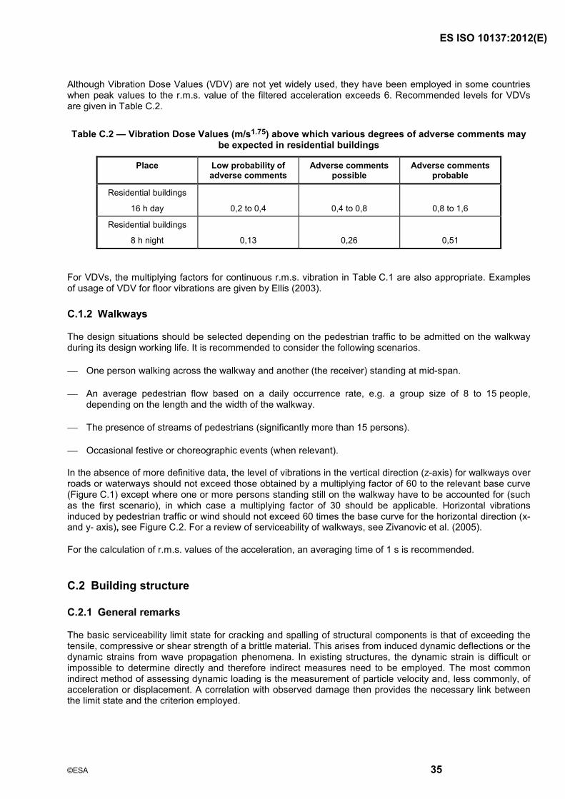
ISO 10137:20 (E)
35
Although Vibration Dose Values (VDV) are not yet widely used, they have been employed in some countries when peak values to the r.m.s. value of the filtered acceleration exceeds 6. Recommended levels for VDVs are given in Table C.2.
Table C.2 �— Vibration Dose Values (m/s1.75) above which various degrees of adverse comments may be expected in residential buildings
Place Low probability of adverse comments
Adverse comments possible
Adverse comments probable
Residential buildings
16 h day
0,2 to 0,4
0,4 to 0,8
0,8 to 1,6
Residential buildings
8 h night
0,13
0,26
0,51
For VDVs, the multiplying factors for continuous r.m.s. vibration in Table C.1 are also appropriate. Examples of usage of VDV for floor vibrations are given by Ellis (2003).
C.1.2 Walkways
The design situations should be selected depending on the pedestrian traffic to be admitted on the walkway during its design working life. It is recommended to consider the following scenarios.
One person walking across the walkway and another (the receiver) standing at mid-span.
An average pedestrian flow based on a daily occurrence rate, e.g. a group size of 8 to 15 people, depending on the length and the width of the walkway.
The presence of streams of pedestrians (significantly more than 15 persons).
Occasional festive or choreographic events (when relevant).
In the absence of more definitive data, the level of vibrations in the vertical direction (z-axis) for walkways over roads or waterways should not exceed those obtained by a multiplying factor of 60 to the relevant base curve (Figure C.1) except where one or more persons standing still on the walkway have to be accounted for (such as the first scenario), in which case a multiplying factor of 30 should be applicable. Horizontal vibrations induced by pedestrian traffic or wind should not exceed 60 times the base curve for the horizontal direction (x- and y- axis), see Figure C.2. For a review of serviceability of walkways, see Zivanovic et al. (2005).
For the calculation of r.m.s. values of the acceleration, an averaging time of 1 s is recommended.
C.2 Building structure
C.2.1 General remarks
The basic serviceability limit state for cracking and spalling of structural components is that of exceeding the tensile, compressive or shear strength of a brittle material. This arises from induced dynamic deflections or the dynamic strains from wave propagation phenomena. In existing structures, the dynamic strain is difficult or impossible to determine directly and therefore indirect measures need to be employed. The most common indirect method of assessing dynamic loading is the measurement of particle velocity and, less commonly, of acceleration or displacement. A correlation with observed damage then provides the necessary link between the limit state and the criterion employed.
ISO 10137:20 (E)
36
Occasionally it may be possible to determine the material strain directly, in which case the measured values should be compared with critical strains. Both for the direct and the indirect method, the dynamic strain is additive to the existing state of strain, the latter being largely an unknown quantity. Consequently, considerable variability exists in the levels of induced dynamic strain (or particle velocity) that correspond to the onset of cracking of the material. Thus there is always a small but finite chance that cracking will occur even for very small levels of dynamic loading, i.e. levels that are lower than those specified in various criteria. For this reason, before undertaking work that may result in significant building vibrations, the person responsible for the project is advised to carry out pre-inspection of potentially vulnerable buildings and document any existing cracks so that these can be discounted from possible damage claims that may result from the work performed.
C.2.2 Vibration criteria for building structure
Since buildings differ greatly in configuration, materials, age, type of foundation and many other factors, sustainable vibrations have largely been specified by empirical rules that vary from country to country and with the type of excitation. Since building construction differs in various countries such rules cannot be expected to apply universally. Damage description and classification of buildings according to their tolerance to vibration effects is presented in ISO 4866. For critical or sensitive situations, special investigations based on structural dynamic principles and on-site trial tests may have to be carried out. Guidance is given in Dowding (1996).
C.2.3 Stadiums and floors of assembly halls
Sustained vibrations of stand structures induced by rhythmic movements of the audience may occur during open air concerts as well as during sports events. The evaluation of the effects on individuals has to distinguish between passive and active persons. For a passive person, i.e. the person who does not participate in the event, relatively small vibration amplitudes are perceptible, while vibration amplitudes have to be large to be perceived by active persons.
Two vibration criteria should be considered. The first criterion is the comfort of the passive part of the audience. The acceptable level of accelerations may be biased by uncontrollable and/or unpredictable parameters like the weather conditions, noisiness of the environment and the general quality of the performance. In the absence of more definitive data, the maximum vibration limit for comfort for a passive person for vertical vibrations may be obtained as the base curve in Figure C.1 with a multiplying factor of 200.
Secondly, the safety of the audience has to be considered. Large vibration amplitudes may alarm both passive and active persons and in extreme cases can result in panic. The limit vibration levels for panic may be higher than for comfort but in any case, vibration amplitudes with a multiplying factor of 400 to the base curve should not be exceeded. Guidance for design of grandstands is given by the Institution of Structural Engineers (2001).
For the calculation of r.m.s.-values from measurements, an averaging time of 10 s is recommended for the comfort criterion, and 1 s for the panic criterion.
C.3 Building contents
C.3.1 General remarks
Buildings contain a great variety of items, from furniture, machinery and computers to highly sophisticated instruments, and their susceptibility to vibrations also varies greatly. Therefore a case-by-case approach needs to be followed. Most common articles in buildings, such as furniture and operating machinery, have a high tolerance to vibrations before they cease to fulfil their intended function. On the other hand, highly sensitive to vibrations are, for example, optical instruments, crystal growing and computer chip manufacturing facilities. Most computers are only moderately sensitive to vibrations. In general, the vibration criteria for satisfactory performance need to be provided by the manufacturer of the equipment.
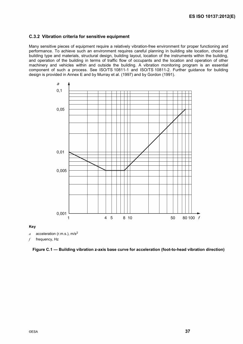
ISO 10137:20 (E)
37
C.3.2 Vibration criteria for sensitive equipment
Many sensitive pieces of equipment require a relatively vibration-free environment for proper functioning and performance. To achieve such an environment requires careful planning in building site location, choice of building type and materials, structural design, building layout, location of the instruments within the building, and operation of the building in terms of traffic flow of occupants and the location and operation of other machinery and vehicles within and outside the building. A vibration monitoring program is an essential component of such a process. See ISO/TS 10811-1 and ISO/TS 10811-2. Further guidance for building design is provided in Annex E and by Murray et al. (1997) and by Gordon (1991).
Key
a acceleration (r.m.s.), m/s2 f frequency, Hz
Figure C.1 �— Building vibration z-axis base curve for acceleration (foot-to-head vibration direction)
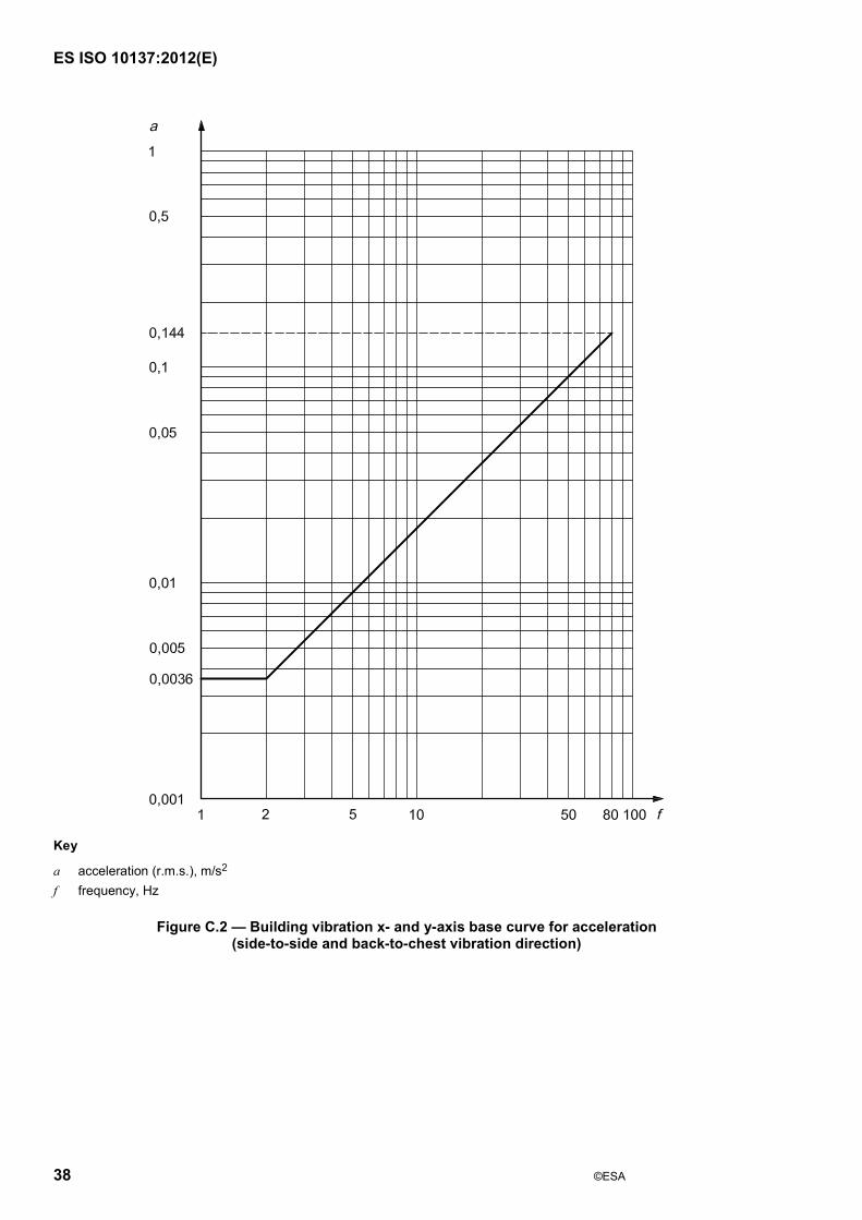
ISO 10137:20 (E)
38
Key
a acceleration (r.m.s.), m/s2 f frequency, Hz
Figure C.2 �— Building vibration x- and y-axis base curve for acceleration (side-to-side and back-to-chest vibration direction)

ISO 10137:20 (E)
39
Key
a acceleration (r.m.s.), m/s2 f frequency, Hz
Figure C.3 �— Building vibration combined direction (x-, y-, z- axis) acceleration base curve
ISO 10137:20 (E)
40
Annex D (informative)
Guidance for human response to wind-induced motions in buildings
D.1 Basic concepts
D.1.1 General remarks
From the viewpoint of keeping within acceptable limits, daily living conditions with respect to human response to relatively ordinary motions of buildings, and horizontal accelerations of building with a one-year return period are applied to the evaluation of habitability.
Other return periods may be adopted, taking into consideration more severe motions due to stronger storms and/or hurricanes that can occur at intervals of several years or decades. For this, multiplying factors other than those used here would apply. The guidance provided applies to regular office and residential occupancy in buildings.
D.1.2 Evaluation curves for acceptable horizontal motions
The evaluation curve for acceptable horizontal motions for �“office�” is specified with peak accelerations at the first natural frequencies in the principal structural directions of the building (normally, along-wind and cross-wind) and in torsion. This is derived from examinations of data for many actual buildings in general use.
The level of the evaluation curve for �“residence�” comes to 2/3 of the curve for office. The resultant curve for residence is close to the 90 % level of the perception probability (Tamura, 2003).
The evaluation curves for acceptable horizontal motions are shown in Figure D.1.
D.1.3 Evaluation of peak building accelerations
Peak building accelerations should be evaluated according to ISO 4354.
D.2 Criteria
D.2.1 Basic rule
The peak accelerations of the target floor, with a one-year return period in the structural directions of the building (normally, along-wind and crosswind) and in torsion should not exceed the basic evaluation curve for the respective occupancy in Figure D.1, in which f0 stands for the first natural frequency in a structural direction of the building and in torsion. Here, the acceleration in torsion stands for the equivalent translational acceleration defined as r A (t), in which r stands for the distance from the centre of torsion to the objective point and A (t), the angular acceleration of the torsional vibration. In more complex situations, a combination of modal responses may be required.

ISO 10137:20 (E)
Key
A peak acceleration, m/s2 f0 first natural frequency in a structural direction of a building and in torsion, Hz
1 offices 2 residences
Figure D.1 �— Evaluation curves for wind-induced vibrations in buildings in a horizontal (x, y) direction for a one-year return period

ISO 10137:20 (E)
42
Annex E (informative)
Methods of vibration mitigation
E.1 Examples of vibration mitigation
The following are some measures that can be employed for reducing vibrations in structures:
a) shift resonance frequency of the transmitting structure or the receiver (change mass or stiffness);
b) add damping to reduce response at resonances (frictional or hydraulic dampers, tuned mass dampers);
c) control the dynamic properties of the source (shift rotational frequency of operation, balance rotating machinery, control traffic speed or route of vehicles, improve surface or subsurface properties of roadway or railway, etc.);
d) isolate the vibration source, such as introduction of barriers to vibration transmission (trenches or piles for ground-transmitted vibrations, proper techniques and air blast control for blasting in the ground);
e) isolate structure by active or passive vibration isolation (servo-controlled mass or reactions, seismic or pneumatic isolation of instruments, spring isolation of building components or of the entire structure).
Care needs to be exercised so that the changes made do not unintentionally deteriorate the vibration levels due to amplifications of hitherto dormant modes of vibration. In general, it is preferable to apply vibration mitigation in the design stages, rather than as a remedial measure after the building is completed and occupied.
E.2 Guidelines for design of buildings that house vibration-sensitive items
E.2.1 General remarks
Quantitative prediction of low vibration levels is often difficult or at least uncertain. Certain strategies may be adopted which should result in diminished vibration levels in buildings. The following can be considered as options in the design process.
E.2.2 Site selection
The location of a new facility should be chosen with a view towards an appropriately low level of vibration. Sources of vibration, such as road or rail traffic, heavy manufacturing processes and quarries should be sufficiently far removed from the site. The existing vibration level in the ground should be monitored for a representative time period and compared with required levels. Both horizontal and vertical levels should be measured. (See ISO 4866.)
E.2.3 Type of foundation and structure
In general, a structure founded on rock will be subject to more high-frequency background vibrations than one founded on soil, but the low-frequency vibration amplitudes will likely be smaller. This may influence the design decision whether to excavate the entire foundation soil to bedrock, employ a foundation on soil, or carry only a pier foundation to the rock or add isolation pads or adopt other vibro-isolation measures.
ISO 10137:20 (E)
43
The type of building structure chosen should provide appropriate rigidity so that internally and externally generated vibrations remain within tolerable levels. Flexible floor construction generates vibrations from walking and other forms of locomotion (wagons, elevators) and from stationary machinery. Mechanical equipment should be located away from the most sensitive areas and adequately isolated against vibration. Wind may induce horizontal vibrations in upper storeys of multi-storey structures. The amplification of vibrations from the foundation to any point of interest in the structure should be considered.
E.2.4 Instrumentation piers
Piers used to support sensitive instruments or processes should be carried to a firm soil layer or rock, and be isolated from rigid contact with the remainder of the building. The main parameters to be considered are
natural frequency of the pier, taking account of the foundation flexibility and elasticity of the material,
natural frequency of the instrument,
frequencies and amplitudes of excitation, and
vibration criteria for the instrument or equipment.
E.2.5 Internal layout of building
Most vibration-sensitive instruments or processes should be located on a slab on grade, or on a pier to bedrock. Service roads or vehicle ramps should be as far removed from the sensitive areas as possible and de-coupled from the building. The use of vibration-isolation devices should be considered where the vibration environment is inadequate. The instrument characteristics (natural frequency, damping, physical dimensions) should be considered in choosing the most appropriate form of isolation (pneumatic, seismic, etc.). Both horizontal and vertical vibrations should be examined and angular or linear motion amplification of tables or other supports taken into account. The sources of vibration internal to the building (persons walking, doors closing, operator movements, auxiliary machinery, changes in air pressure due to door openings, etc.) should be addressed.
E.2.6 Remedial measures
Where vibration levels exceed the recommended levels or where they interfere with satisfactory operation, modifications to the structure or methods of vibration isolation of individual instruments or group of instruments may be required. Some available options are described in E.1.

ISO 10137:20 (E)
44
Bibliography
[1] ALLEN, D.E., ONYSKO, D.M., and MURRAY, T.M. Minimizing Floor Vibration. ATC Design Guide 1, Applied Technology Council, Redwood City, CA, USA, 1999, 49 pp.
[2] BISHOP, N.W.M., WILLFORD, M. and PUMPHREY, R. Human induced loading of flexible staircases. Safety Science 18 (1995), pp. 261 �– 276
[3] DALLARD, P. et al. The London Millennium Bridge. The Structural Engineer 9/22, Nov. 2001
[4] DOWDING, C.H. Construction Vibrations. Prentice-Hall, Upper Saddle River, NJ, USA, 1996, 610 pp.
[5] ELLIS, B.R. The influence of crowd size on floor vibrations induced by walking. The Structural Engineer, 18 March 2003, pp. 20 �– 27
[6] GORDON, C.G. Generic criteria for vibration-sensitive equipment. SPIE, vol.1619, 1991, San Jose CA, USA, pp. 71-85
[7] Institution of Structural Engineers. Dynamic performance requirements for permanent grandstands subject to crowd action - Interim guidance on assessment and design. The Institution of Structural Engineers London, UK, November 2001
[8] KANDA, J., TAMURA, Y., NAKAMURA, O., and UESU, K., Probabilistic criteria for serviceability limit of wind response, Int�’l Colloquium on Structural Serviceability of Building, Goteborg, Sweden, IABSE Reports, Vol. 69, 1993, pp. 59-66
[9] LANGEFORS, V. and KIHLSTROM, B. The Modem Technique of Rock Blasting. John Wiley, New York, USA, 1976
[10] MELBOURNE, W.H. and PALMER, T.R. Accelerations and comfort criteria for buildings and undergoing complex motions, Journal of Wind Engineering and Industrial Aerodynamics, 41-44, 1992, pp. 105-116
[11] MURRAY, T.M., ALLEN, D.E. and UNGAR, E.E. Floor Vibrations due to Human Activity, Steel Design Guide Series 11, American Institute of Steel Construction, Chicago IL, USA, 1997, 69 pp.
[12] NAKAMURA, S-I. Field measurements of lateral vibration on a pedestrian suspension bridge. The Structural Engineer, 18 November 2003, pp. 22 �– 26
[13] OHLSSON, S. Springiness and Human Induced Floor Vibrations �— A Design Guide. Swedish Council for Building Research, Stockholm, Sweden, 1988, 139 pp. (Document D12)
[14] TAMURA, Y. Design issues for tall buildings from accelerations to damping, The 11th International Conference on Wind Engineering, Lubbock, Texas, June, 2003
[15] WYATT, T.A. Design guide on the vibration of floors. SCI Publication 076. The Steel Construction Institute, Berkshire. UK, 1989, 32 pp.
[16] ZIVANOVIC, S., PAVIC, A., and REYNOLDS, P. Vibration serviceability of footbridges under human-induced excitation: a literature review. J. Sound and Vibration, 279 (1-2), 2005, pp. 1 �– 74

The Head Office of ESA is at Addis Ababa.
011-‐ 646 06 85, 011-‐ 646 05 65 011-‐646 08 80 2310 Addis Ababa, Ethiopia
E-‐mail: [email protected], Website: www.ethiostandards.org
Organization and Objectives
The Ethiopian Standards Agency (ESA) is the national standards body of Ethiopia established in 2010 based on regulation No. 193/2010.ESA is established due to the restructuring of Quality and Standards Authority of Ethiopia (QSAE) which was established in 1970.
ESA’s objectives are:-
Develop Ethiopian standards and establish a system that enable to check weather goods and services are in compliance with the required standards, Facilitate the country’s technology transfer through the use of standards, Develop national standards for local products and services so as to make them competitive in the international market.
Ethiopian Standards
The Ethiopian Standards are developed by national technical committees which are composed of different stakeholders consisting of educational Institutions, research institutes, government organizations, certification, inspection, and testing organizations, regulatory bodies, consumer association etc. The requirements and/ or recommendations contained in Ethiopian Standards are consensus based that reflects the interest of the TC representatives and also of comments received from the public and other sources. Ethiopian Standards are approved by the National Standardization Council and are kept under continuous review after publication and updated regularly to take account of latest scientific and technological changes. Orders for all Ethiopian Standards, International Standard and ASTM standards, including electronic versions, should be addressed to the Documentation and Publication Team at the Head office and Branch (Liaisons) offices. A catalogue of Ethiopian Standards is also available freely and can be accessed in from our website.
ESA has the copyright of all its publications. No part of these publications may be reproduced in any form without the prior permission in writing of ESA. International Involvement ESA, representing Ethiopia, is a member of the International Organization for Standardization (ISO), and Codex Alimentarius Commission (CODEX). It also maintains close working relations with the international Electro-technical Commission (IEC) and American Society for Testing and Materials (ASTM).It is a founding member of the African Regional Organization for standardization (ARSO).
More Information?
Contact us at the following address.
Standard Mark
Eth
iopi
an S
tand
ards
Age
ncy
DRAFT

ISO 10137:2007(E)
ICS 91.080.01; 91.120.25 Price based on 44 pages
© ISO 2007 �– All rights reserved
DRAFT


