20
Application Edition 03/05 ET200S FC Start-up ET200S FC

Application Edition 03/05
ET200S FC Start-up ET200S FC

Copyright Edition 03/05
2 ET200S FC Application MM4Appl_014_ET200S FC Startup
Copyright
The reproduction, transmission or use of this document or its contents is not permitted without express written authority. Offenders will be liable for damages. All rights, including rights created by patent grant or registration of a utility model or design, are reserved.

Edition 03/05 Definitions and Warnings
ET200S FC Application 3 MM4Appl_014_ET200S FC Startup
Definitions and Warnings
Qualified personnel In the sense of this documentation qualified personnel are those who are knowledgeable and qualified to install, mount, commission, operate and service/maintain the products to be used, e.g. they are:
Trained and authorized to energize and de-energize, ground and tag circuits and equipment according to applicable safety standards.
Trained or instructed according to the latest safety standards in the care and use of the appropriate safety equipment.
Trained in rendering first aid.
There is no explicit warning information in this documentation. However, reference is made to warning information and instructions in the Operating Instructions for the particular product.
User group Only qualified personnel may use the application software and the application example.
If this is incorrectly used, this can result in the plant or system being destroyed and/or injury to personnel.
Please also note the Chapters „Safety informations and instructions“ and „Important informations and instructions“ of the Operating Instructions and „Important Notes“ of the List Manuel, of the Frequency Converter ET200S FC.
Information regarding trademarks SIMATIC ® is a Siemens trademark ET200S FC ® is a Siemens trademark
Contents Edition 03/05
4 ET200S FC Application MM4Appl_014_ET200S FC Startup
Contents
1 Functional scope .................................................................................................... 3
2 Hardware prerequisites.......................................................................................... 3
3 Software prerequisites ........................................................................................... 3
4 Installing the program example............................................................................. 3 4.1 Integrating the program example.............................................................................. 3 4.2 Adapting the program example to your HW Config .................................................. 3
5 Controlling the ET200S FC via variable tables .................................................... 3 5.1 Variable table "Step 1, control signals"..................................................................... 3 5.2 Variable table "Step 2, control signals"..................................................................... 3 5.3 Variable table "Step 3, read parameters" ................................................................. 3 5.4 Variable table "Step 4, write parameter"................................................................... 3

Edition 03/05 Functional scope
ET200S FC Application 5 MM4Appl_014_ET200S FC Startup
1 Functional scope Using a specific program example, these instructions explain how an ET200S FC frequency converter is controlled using the FB100. You will learn about the individual FB100 functions step-by-step using several variable tables.
This program example will not discuss the parameterization of the ET200S FC using the "Starter" commissioning software. An ET200S FC frequency converter that has already been commissioned is required for the program example.

Hardware prerequisites Edition 03/05
6 ET200S FC Application MM4Appl_014_ET200S FC Startup
2 Hardware prerequisites The following hardware components are required to operate the ET200S FC:
- SIMATIC S7-300 or SIMATIC S7-400 with integrated Profibus-DP interface. As an alternative, you can also use an ET200S IM151-7 CPU.
- ET200S system with IM151 interface module and PM-D power module when using the ICU24 (standard converter) or power module PM-D FX1 or PM-D F Profisafe when using the ICU24 F (fail-safe frequency converter).
- ET200S FC frequency converter, comprising an ICU24 or ICU24 F control unit and IPM25 power module with the appropriate terminal modules.

Edition 03/05 Software prerequisites
ET200S FC Application 7 MM4Appl_014_ET200S FC Startup
3 Software prerequisites - STEP 7 from version 5.2, service pack 1 or higher plus the Hardware
Support Package (HSP). It is downloaded into STEP 7 directly from HW Config. The correct link is pre-set there.
- When using the Powermodul “PM-D F PROFIsave”, in addition, the "S7 Distributed Safety V5.2" software package is required.

Installing the program example Edition 03/05
8 ET200S FC Application MM4Appl_014_ET200S FC Startup
4 Installing the program example
4.1 Integrating the program example
- Generate a new project using the SIMATIC Manager.
- Enter a hardware configuration corresponding to the hardware that you are using. For more detailed information, please refer to the ET200S FC Operating Instructions in Chapter "Connection to SIMATIC S7“, "Creating the hardware configuration in the SIMATIC Manager“.
- In the SIMATIC Manager open the "ET200S_FC_Startup“ project via "File", "Open", "Sample projects" – and copy all of the blocks from the "Blocks" folder into the "Blocks" folder of your project.

Edition 03/05 Installing the program example
ET200S FC Application 9 MM4Appl_014_ET200S FC Startup
4.2 Adapting the program example to your HW Config
- Open the HW Config of your program and read-out the starting address of the ET200S FC ICU. In this example, it is 256.
- Convert this address into the hexadecimal notation. In the example, this results in an address of 100 HEX.
Installing the program example Edition 03/05
10 ET200S FC Application MM4Appl_014_ET200S FC Startup
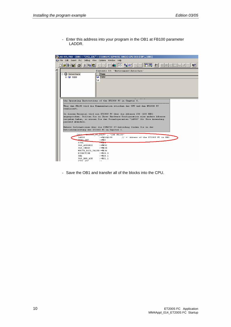
- Enter this address into your program in the OB1 at FB100 parameter LADDR.
- Save the OB1 and transfer all of the blocks into the CPU.
Edition 03/05 Controlling the ET200S FC via variable tables
ET200S FC Application 11 MM4Appl_014_ET200S FC Startup
5 Controlling the ET200S FC via variable tables When you copy the blocks from the program example, you also transfer four variable tables. Using these variable tables, you will now get to know how to control the ET200S FC using the FB100. With the experience that you then gain, you should be in a position to integrate the FB100 into your user program and use it to control the ET200S FC.
In this program example, the FB100 is controlled using flag bits. For your infomations, in the following description, in addition to the flag bits in brackets, there are also the actual parameters of the FB100.

Controlling the ET200S FC via variable tables Edition 03/05
12 ET200S FC Application MM4Appl_014_ET200S FC Startup
5.1 Variable table "Step 1, control signals"
In this variable table, the control signals of the ET200S FC are supplied via the FB100 and the status signals of the ET200S FC are displayed via the FB100.
The variable table is structured as follows:
Upper section (control signals):
- You can enter the setpoint (target) frequency via MW2 (FREQ_SET). By entering the HEX value W#16#4000 the motor rotates with 100 % of the reference frequency that was entered using p2000. When entering the W#16#1000, then the motor rotates with 25 % of the reference frequency.
- The motor is started and stopped using the MW6 (CTRL). The motor is started by enter the HEX value W#16#047F. The motor is stopped by enter the HEX value W#16#047E .
Center section (status signals):
- The actual motor frequency is displayed at MW12 (FREQ). The values should be interpreted the same as the setpoint (target) frequency. This means that the value W#16#4000 corresponds to 100 % of the reference frequency (p2000).
- In addition, all of the status signals that are read-out from FB100 in the ET200S FC are available in MD14 (STAT). To make it easier to understand, the most important status signals (M17.0 to M17.7), which are contained in MD14 (STAT), are listed. Please refer to the ET200S FC List

Edition 03/05 Controlling the ET200S FC via variable tables
ET200S FC Application 13 MM4Appl_014_ET200S FC Startup
Manual, Chapter 2, Function charts, function chart 2710 for the additional status signals.
Lower section (fault messages/signals):
Two different types of fault messages/signals are output via the FB100.
- M20.1 (ERR_NO_VALID) and MW26 (ERR_NO): M20.1 indicates that the ET200S FC has a fault condition. The appropriate fault number can be taken from the MW26. For more detailed information about the fault, please refer to the ET200S FC List Manual, from Chapter “Faults and Alarms” onwards.
- You can acknowledge this fault via the M7.7. For example, if the ET200S FC has more than one Error, the first acknowledgement does not cancel any existing error. It is only displays the second error in FB100. All existing errors of ET200S FC are reset with the second acknowledgement.
- M20.0 (SFC_ERR), MW22 (SFC_ERR_RD) and MW24 (SFC_ERR_WR): M20.0 signals to you that an error has occurred in the Profibus coupling between the PLC and the ET200S FC via the standard SFC14 or SFC15 blocks. For more detailed information about the faults/errors, please refer to the Tables “Error numbers for SFC_ERR_RD” and “Error numbers for SFC_ERR_WR” in Chapter “Connection to SIMATIC S7” of the ET200S FC Operating Instructions.

Controlling the ET200S FC via variable tables Edition 03/05
14 ET200S FC Application MM4Appl_014_ET200S FC Startup
5.2 Variable table "Step 2, control signals"
This variable table should be considered as a continuation of the previous variable table. However, the difference to the previous one is the fact that control word (MD4) is broken-down with the most important control signals. Please refer to the ET200S FC List Manual, Chapter “Function charts, function chart 2700” for the additional control signals.
The variable table is structured as follows:
Upper section (control signals):
- Just as in the previous variable table, also here, you have the possibility of entering the setpoint (target) frequency via the MW2 (FREQ_SET). By entering the HEX value W#16#4000 the motor rotates with 100 % of the reference frequency that was entered using p2000. When entering the value W#16#1000, then the motor rotates with 25 % of the reference frequency.

Edition 03/05 Controlling the ET200S FC via variable tables
ET200S FC Application 15 MM4Appl_014_ET200S FC Startup
- The control word MD4 (CTRL) is, in this variable table, broken-down into the most important control bits. The function of the control bits used is shown below:
o M6.2: From Version V2.2 of the FB100, it is no longer necessary to set this bit to signal 1. FB100 automatically set this bit.
o M7.1 to M7.6: Signal 1 for all control bits switches the ET200S FC into the "Drive ready" state (M17.0).
o M7.0: Signal 1 starts the motor. If these control signal is used, then M6.0 (JOG right) and M6.1 (JOG left) must have the signal 0.
o M6.3: Setpoint reversal (the motor direction of rotation is reversed).
o M6.0 or M6.1: The JOG frequency for right (p1058) or left (p1059) is controlled using these two control bits. If these control signals are used, then M7.0 must have the signal 0.
Lower section (status signals):
- The actual motor frequency is displayed at MW12 (FREQ). The values should be interpreted the same as the setpoint (target) frequency. This means that the value W#16#4000 corresponds to 100 % of the reference frequency (p2000).
- Further, all of the status signals that are read-out from FB100 in the ET200S FC are available in MD14 (STAT). In order to obtain a better understanding, the most important status signals (M17.0 to M17.7), which are contained in MD14, are listed. Please refer to the ET200S FC List Manual, Chapter “Function charts, function chart 2710” for the additional status signals.

Controlling the ET200S FC via variable tables Edition 03/05
16 ET200S FC Application MM4Appl_014_ET200S FC Startup
5.3 Variable table "Step 3, read parameters"
In this variable table, the control signals to read parameters from the ET200S FC are supplied via the FB100 and possible error messages when reading parameters, are displayed.
The variable table is structured as follows:
Upper section (read parameters):
- Enter the number of the parameter that you wish to read-out of the ET200S FC using MW32 (PAR_ADRESS) and the index of the parameter using MB34 (PAR_INDEX).
- In order to read parameters, you must assign signal 0 to M30.0 (DIRECTION).
- The read operation is started with a signal edge at M30.1 (REQ). While reading, the M30.2 (BUSY) changes from signal 0 to signal 1. Once the read operation has been completed, M30.2 (BUSY) changes back to signal 0 and the value of the read parameter is output via the MD40 (READ_DATA_VALUE).
- Please take the format of the value (DEC or FLOATING-POINT) from the ET200S FC List Manuel, Chapter “Parameter Description” (header line of the parameter, data type, U16 or U32 = DEC, Float = FLOATING-POINT).
Lower section (error when reading/writing into parameters):
- If an error occurred when reading a parameter (e.g. a parameter was to be read that does not exist), the status of M31.0 (PAR_ERR) changes from

Edition 03/05 Controlling the ET200S FC via variable tables
ET200S FC Application 17 MM4Appl_014_ET200S FC Startup
signal 0 to signal 1. You can then read-out the corresponding error number in MB44 (PAR_ERR_NO). More detailed information on the cause of the error can be taken from the error number in Table “Parameterizing error numbers” in Chapter “Connection to SIMATIC S7” of the ET200S FC Operating Instructions.
- You can acknowledge the error message using M31.1 (PAR_ERR_ACK).

Controlling the ET200S FC via variable tables Edition 03/05
18 ET200S FC Application MM4Appl_014_ET200S FC Startup
5.4 Variable table "Step 4, write parameter"
In this variable table, the control signals to write into parameters of the ET200S FC are supplied via the FB100 and possible error messages when writing into the parameters are displayed.
The variable table is structured as follows:
Upper section (write to parameter):
- Enter the number of the parameter that you wish to write into the ET200S FC using MW32 (PAR_ADRESS) and the index of the parameter using MB34 (PAR_INDEX).
- Enter the value of the parameter to be written into using the MD36 (WRITE_DATA_VALUE).
- Please take the format of the value (DEC or FLOATING-POINT) from the ET200S FC List Manuel, Chapter “Parameter Description” (header line of the parameter, data type, U16 or U32 = DEC, Float = FLOATING-POINT).
- In order to write into parameters you must assign the signal 1 to M30.0
(DIRECTION).
- The write operation is started with a signal edge at M30.1 (REQ). While writing, M30.2 (BUSY) changes from signal 0 to signal 1. Once the write operation has been completed, M30.2 (BUSY) changes back to signal 0.
Lower section (error when reading/writing into parameters):
- If an error occurred when writing into a parameter (e.g. a parameter was to be changed that cannot be changed in the current operating state of the ET200S FC), then the status of the M31.0 (PAR_ERR) changes from

Edition 03/05 Controlling the ET200S FC via variable tables
ET200S FC Application 19 MM4Appl_014_ET200S FC Startup
signal 0 to signal 1. You can then read-out the corresponding error number in MB44 (PAR_ERR_NO). More detailed information on the cause of the error can be taken from the error number in Table “Parameterizing error numbers” in Chapter “Connection to SIMATIC S7” of the ET200S FC Operating Instructions.
- You can acknowledge the error message using M31.1 (PAR_ERR_ACK).

Siemens AG
Automation and Drives
Standard Drives
Postfach 3269, D – 91050 Erlangen
Republic of Germany
www.ad.siemens.de
© Siemens AG 2005 We reserve the right to make changes
MM4Appl_014_ET200S FC Startup


![Et200s 2ao u St Manual en-US[1]](https://static.documents.pub/doc/80x56/577dac241a28ab223f8d7aa9/et200s-2ao-u-st-manual-en-us1.jpg)


![Et200s Im151 1 Basic Manual en-US en-US[1]](https://static.documents.pub/doc/80x56/55378db44a795967228b4dd6/et200s-im151-1-basic-manual-en-us-en-us1.jpg)


