81
ETAS XETK-S30.0 Emulator Probe for Infineon AURIX MCU Family User Guide

ETAS XETK-S30.0 Emulator Probe for Infineon AURIX MCU Family
User Guide

Copyright
The data in this document may not be altered or amended without special noti-fication from ETAS GmbH. ETAS GmbH undertakes no further obligation in relation to this document. The software described in it can only be used if the customer is in possession of a general license agreement or single license. Using and copying is only allowed in concurrence with the specifications stipu-lated in the contract.
Under no circumstances may any part of this document be copied, reproduced, transmitted, stored in a retrieval system or translated into another language without the express written permission of ETAS GmbH.
© Copyright 2021 ETAS GmbH, Stuttgart
The names and designations used in this document are trademarks or brands belonging to the respective owners.
XETK-S30.0 - User Guide R14 EN - 06.2021

ETAS Contents
Contents
XETK-S30.0 - User Guide 3
1 About this Document . . . . . . . . . . . . . . . . . . . . . . . . . . . . . . . . . . . . . . . . . . . . . . . . . . . 71.1 Classification of Safety Messages . . . . . . . . . . . . . . . . . . . . . . . . . . . . . . . . . . . . . . . . . . 7
1.2 Presentation of Instructions . . . . . . . . . . . . . . . . . . . . . . . . . . . . . . . . . . . . . . . . . . . . . . . 7
1.3 Typographical Conventions . . . . . . . . . . . . . . . . . . . . . . . . . . . . . . . . . . . . . . . . . . . . . . . . 8
1.4 Presentation of Supporting Information . . . . . . . . . . . . . . . . . . . . . . . . . . . . . . . . . . . . . 8
2 Basic Safety Notices . . . . . . . . . . . . . . . . . . . . . . . . . . . . . . . . . . . . . . . . . . . . . . . . . . . 92.1 General Safety Information . . . . . . . . . . . . . . . . . . . . . . . . . . . . . . . . . . . . . . . . . . . . . . . . 9
2.2 Requirements for Users and Duties for Operators . . . . . . . . . . . . . . . . . . . . . . . . . . . . 9
2.3 Intended Use. . . . . . . . . . . . . . . . . . . . . . . . . . . . . . . . . . . . . . . . . . . . . . . . . . . . . . . . . . . . . 9
2.4 Identifications on the Product . . . . . . . . . . . . . . . . . . . . . . . . . . . . . . . . . . . . . . . . . . . . . 12
2.5 Taking the Product Back and Recycling . . . . . . . . . . . . . . . . . . . . . . . . . . . . . . . . . . . . 13
2.6 Declaration of Conformity . . . . . . . . . . . . . . . . . . . . . . . . . . . . . . . . . . . . . . . . . . . . . . . . 132.6.1 CE Declaration of Conformity (European Union) . . . . . . . . . . . . . . . . . . . . 132.6.2 UKCA Declaration of Conformity (Great Britain) . . . . . . . . . . . . . . . . . . . . 14
2.7 RoHS Conformity . . . . . . . . . . . . . . . . . . . . . . . . . . . . . . . . . . . . . . . . . . . . . . . . . . . . . . . . 142.7.1 European Union . . . . . . . . . . . . . . . . . . . . . . . . . . . . . . . . . . . . . . . . . . . . . . . . 142.7.2 People’s Republic of China. . . . . . . . . . . . . . . . . . . . . . . . . . . . . . . . . . . . . . . 14
2.8 Declarable Substances . . . . . . . . . . . . . . . . . . . . . . . . . . . . . . . . . . . . . . . . . . . . . . . . . . . 14
2.9 Use of Open Source Software . . . . . . . . . . . . . . . . . . . . . . . . . . . . . . . . . . . . . . . . . . . . . 14
3 Introduction. . . . . . . . . . . . . . . . . . . . . . . . . . . . . . . . . . . . . . . . . . . . . . . . . . . . . . . . . 153.1 Applications . . . . . . . . . . . . . . . . . . . . . . . . . . . . . . . . . . . . . . . . . . . . . . . . . . . . . . . . . . . . 15
3.2 Features. . . . . . . . . . . . . . . . . . . . . . . . . . . . . . . . . . . . . . . . . . . . . . . . . . . . . . . . . . . . . . . . 16
4 Hardware Description . . . . . . . . . . . . . . . . . . . . . . . . . . . . . . . . . . . . . . . . . . . . . . . . 174.1 Architecture. . . . . . . . . . . . . . . . . . . . . . . . . . . . . . . . . . . . . . . . . . . . . . . . . . . . . . . . . . . . . 17
4.2 ECU Interface . . . . . . . . . . . . . . . . . . . . . . . . . . . . . . . . . . . . . . . . . . . . . . . . . . . . . . . . . . . 19
4.3 XETK Ethernet Interface . . . . . . . . . . . . . . . . . . . . . . . . . . . . . . . . . . . . . . . . . . . . . . . . . . 20
4.4 Power Supply . . . . . . . . . . . . . . . . . . . . . . . . . . . . . . . . . . . . . . . . . . . . . . . . . . . . . . . . . . . 21
4.5 ECU Voltage Supervisor . . . . . . . . . . . . . . . . . . . . . . . . . . . . . . . . . . . . . . . . . . . . . . . . . . 22
4.6 Data Emulation and Data Measurement . . . . . . . . . . . . . . . . . . . . . . . . . . . . . . . . . . . . 234.6.1 Page Switching. . . . . . . . . . . . . . . . . . . . . . . . . . . . . . . . . . . . . . . . . . . . . . . . . 23
4.7 DAP Interface . . . . . . . . . . . . . . . . . . . . . . . . . . . . . . . . . . . . . . . . . . . . . . . . . . . . . . . . . . . 25
4.8 Trigger Modes: Overview . . . . . . . . . . . . . . . . . . . . . . . . . . . . . . . . . . . . . . . . . . . . . . . . . 26
4.9 Pinless Triggering . . . . . . . . . . . . . . . . . . . . . . . . . . . . . . . . . . . . . . . . . . . . . . . . . . . . . . . 264.9.1 Startup Handshake . . . . . . . . . . . . . . . . . . . . . . . . . . . . . . . . . . . . . . . . . . . . . 264.9.2 XETK Trigger Generation . . . . . . . . . . . . . . . . . . . . . . . . . . . . . . . . . . . . . . . . 26
4.10 Timer Triggering. . . . . . . . . . . . . . . . . . . . . . . . . . . . . . . . . . . . . . . . . . . . . . . . . . . . . . . . . 27
4.11 Reset . . . . . . . . . . . . . . . . . . . . . . . . . . . . . . . . . . . . . . . . . . . . . . . . . . . . . . . . . . . . . . . . . . 27
4.12 Pull CalWakeUp until Startup Handshake . . . . . . . . . . . . . . . . . . . . . . . . . . . . . . . . . . . 27
Contents

ETAS Contents
XETK-S30.0 - User Guide 4
5 Installation . . . . . . . . . . . . . . . . . . . . . . . . . . . . . . . . . . . . . . . . . . . . . . . . . . . . . . . . . 285.1 Connection to the ECU . . . . . . . . . . . . . . . . . . . . . . . . . . . . . . . . . . . . . . . . . . . . . . . . . . . 28
5.2 Wiring . . . . . . . . . . . . . . . . . . . . . . . . . . . . . . . . . . . . . . . . . . . . . . . . . . . . . . . . . . . . . . . . . . 305.2.1 XETK Ethernet Interface . . . . . . . . . . . . . . . . . . . . . . . . . . . . . . . . . . . . . . . . . 305.2.2 Power Supply . . . . . . . . . . . . . . . . . . . . . . . . . . . . . . . . . . . . . . . . . . . . . . . . . . 31
6 XETK Configuration . . . . . . . . . . . . . . . . . . . . . . . . . . . . . . . . . . . . . . . . . . . . . . . . . . 326.1 Overview . . . . . . . . . . . . . . . . . . . . . . . . . . . . . . . . . . . . . . . . . . . . . . . . . . . . . . . . . . . . . . . 32
6.2 Configuration Parameter . . . . . . . . . . . . . . . . . . . . . . . . . . . . . . . . . . . . . . . . . . . . . . . . . 33
7 Technical Data . . . . . . . . . . . . . . . . . . . . . . . . . . . . . . . . . . . . . . . . . . . . . . . . . . . . . . 347.1 System Requirements. . . . . . . . . . . . . . . . . . . . . . . . . . . . . . . . . . . . . . . . . . . . . . . . . . . . 34
7.1.1 ETAS Compatible Hardware . . . . . . . . . . . . . . . . . . . . . . . . . . . . . . . . . . . . . 347.1.2 PC with one Ethernet Interface . . . . . . . . . . . . . . . . . . . . . . . . . . . . . . . . . . . 347.1.3 Software Support . . . . . . . . . . . . . . . . . . . . . . . . . . . . . . . . . . . . . . . . . . . . . . . 35
7.2 Data Emulation and Measurement Memory. . . . . . . . . . . . . . . . . . . . . . . . . . . . . . . . . 367.2.1 Data Emulation Memory and Microcontroller Support . . . . . . . . . . . . . . . 367.2.2 Measurement Data Memory . . . . . . . . . . . . . . . . . . . . . . . . . . . . . . . . . . . . . 36
7.3 Configuration . . . . . . . . . . . . . . . . . . . . . . . . . . . . . . . . . . . . . . . . . . . . . . . . . . . . . . . . . . . 36
7.4 XETK Ethernet Interface . . . . . . . . . . . . . . . . . . . . . . . . . . . . . . . . . . . . . . . . . . . . . . . . . 37
7.5 Environmental Conditions . . . . . . . . . . . . . . . . . . . . . . . . . . . . . . . . . . . . . . . . . . . . . . . . 37
7.6 Power Supply . . . . . . . . . . . . . . . . . . . . . . . . . . . . . . . . . . . . . . . . . . . . . . . . . . . . . . . . . . . 38
7.7 Microcontroller Interface . . . . . . . . . . . . . . . . . . . . . . . . . . . . . . . . . . . . . . . . . . . . . . . . . 39
7.8 Test Characteristics . . . . . . . . . . . . . . . . . . . . . . . . . . . . . . . . . . . . . . . . . . . . . . . . . . . . . 39
7.9 DAP Timing Characteristics. . . . . . . . . . . . . . . . . . . . . . . . . . . . . . . . . . . . . . . . . . . . . . . 407.9.1 DAP Timing Diagram. . . . . . . . . . . . . . . . . . . . . . . . . . . . . . . . . . . . . . . . . . . . 407.9.2 DAP Timing Diagram DAP Timing Parameter . . . . . . . . . . . . . . . . . . . . . . 40
7.10 Electrical Characteristics . . . . . . . . . . . . . . . . . . . . . . . . . . . . . . . . . . . . . . . . . . . . . . . . . 417.10.1 ECU Interface Connector . . . . . . . . . . . . . . . . . . . . . . . . . . . . . . . . . . . . . . . . 41
7.11 Pin Assignment . . . . . . . . . . . . . . . . . . . . . . . . . . . . . . . . . . . . . . . . . . . . . . . . . . . . . . . . . 427.11.1 XETK-S30.0 Interface Location . . . . . . . . . . . . . . . . . . . . . . . . . . . . . . . . . . . 427.11.2 XETK Ethernet Interface Connector CON1 . . . . . . . . . . . . . . . . . . . . . . . . . 427.11.3 ECU Interface Connector CON2 . . . . . . . . . . . . . . . . . . . . . . . . . . . . . . . . . . 437.11.4 VDDSTBY_SENSE Connector CON3. . . . . . . . . . . . . . . . . . . . . . . . . . . . . . . 437.11.5 Power Supply Connector CON4 . . . . . . . . . . . . . . . . . . . . . . . . . . . . . . . . . . 44
7.12 Mechanical Dimensions . . . . . . . . . . . . . . . . . . . . . . . . . . . . . . . . . . . . . . . . . . . . . . . . . . 457.12.1 Top View . . . . . . . . . . . . . . . . . . . . . . . . . . . . . . . . . . . . . . . . . . . . . . . . . . . . . . 457.12.2 Side View . . . . . . . . . . . . . . . . . . . . . . . . . . . . . . . . . . . . . . . . . . . . . . . . . . . . . . 46
8 Cables and Accessories . . . . . . . . . . . . . . . . . . . . . . . . . . . . . . . . . . . . . . . . . . . . . . 478.1 Overview and Classification. . . . . . . . . . . . . . . . . . . . . . . . . . . . . . . . . . . . . . . . . . . . . . . 47
8.2 Requirements for failsafe Operation . . . . . . . . . . . . . . . . . . . . . . . . . . . . . . . . . . . . . . . 47
8.3 CBAM230 Cable . . . . . . . . . . . . . . . . . . . . . . . . . . . . . . . . . . . . . . . . . . . . . . . . . . . . . . . . . 488.3.1 Usage . . . . . . . . . . . . . . . . . . . . . . . . . . . . . . . . . . . . . . . . . . . . . . . . . . . . . . . . . 488.3.2 Mechanical Dimensions . . . . . . . . . . . . . . . . . . . . . . . . . . . . . . . . . . . . . . . . . 488.3.3 Panel Cut-Out . . . . . . . . . . . . . . . . . . . . . . . . . . . . . . . . . . . . . . . . . . . . . . . . . . 488.3.4 Assembling . . . . . . . . . . . . . . . . . . . . . . . . . . . . . . . . . . . . . . . . . . . . . . . . . . . . 488.3.5 Temperature Range. . . . . . . . . . . . . . . . . . . . . . . . . . . . . . . . . . . . . . . . . . . . . 49

ETAS Contents
XETK-S30.0 - User Guide 5
8.3.6 Ordering Information . . . . . . . . . . . . . . . . . . . . . . . . . . . . . . . . . . . . . . . . . . . . 498.4 CBAM240 Cable . . . . . . . . . . . . . . . . . . . . . . . . . . . . . . . . . . . . . . . . . . . . . . . . . . . . . . . . . 50
8.4.1 Usage . . . . . . . . . . . . . . . . . . . . . . . . . . . . . . . . . . . . . . . . . . . . . . . . . . . . . . . . . 508.4.2 Mechanical Dimensions . . . . . . . . . . . . . . . . . . . . . . . . . . . . . . . . . . . . . . . . . 508.4.3 Mounting Proposal with an EMC safe Cable Gland. . . . . . . . . . . . . . . . . . 508.4.4 Temperature Range. . . . . . . . . . . . . . . . . . . . . . . . . . . . . . . . . . . . . . . . . . . . . 518.4.5 Ordering Information . . . . . . . . . . . . . . . . . . . . . . . . . . . . . . . . . . . . . . . . . . . . 51
8.5 CBAM271 Cable . . . . . . . . . . . . . . . . . . . . . . . . . . . . . . . . . . . . . . . . . . . . . . . . . . . . . . . . . 528.5.1 Usage . . . . . . . . . . . . . . . . . . . . . . . . . . . . . . . . . . . . . . . . . . . . . . . . . . . . . . . . . 528.5.2 Mechanical Dimensions . . . . . . . . . . . . . . . . . . . . . . . . . . . . . . . . . . . . . . . . . 528.5.3 Mounting . . . . . . . . . . . . . . . . . . . . . . . . . . . . . . . . . . . . . . . . . . . . . . . . . . . . . . 528.5.4 Temperature Range. . . . . . . . . . . . . . . . . . . . . . . . . . . . . . . . . . . . . . . . . . . . . 528.5.5 Ordering Information . . . . . . . . . . . . . . . . . . . . . . . . . . . . . . . . . . . . . . . . . . . . 52
8.6 ETAM2 ECU Adapter . . . . . . . . . . . . . . . . . . . . . . . . . . . . . . . . . . . . . . . . . . . . . . . . . . . . . 538.6.1 Pin Assignment . . . . . . . . . . . . . . . . . . . . . . . . . . . . . . . . . . . . . . . . . . . . . . . . 538.6.2 ECU Signals. . . . . . . . . . . . . . . . . . . . . . . . . . . . . . . . . . . . . . . . . . . . . . . . . . . . 538.6.3 Ordering Information . . . . . . . . . . . . . . . . . . . . . . . . . . . . . . . . . . . . . . . . . . . . 53
8.7 ETAM3 ECU Adapter . . . . . . . . . . . . . . . . . . . . . . . . . . . . . . . . . . . . . . . . . . . . . . . . . . . . . 548.7.1 Usage . . . . . . . . . . . . . . . . . . . . . . . . . . . . . . . . . . . . . . . . . . . . . . . . . . . . . . . . . 548.7.2 Mechanical Dimensions . . . . . . . . . . . . . . . . . . . . . . . . . . . . . . . . . . . . . . . . . 548.7.3 Pin Assignment . . . . . . . . . . . . . . . . . . . . . . . . . . . . . . . . . . . . . . . . . . . . . . . . 548.7.4 ECU Signals. . . . . . . . . . . . . . . . . . . . . . . . . . . . . . . . . . . . . . . . . . . . . . . . . . . . 558.7.5 Temperature Range. . . . . . . . . . . . . . . . . . . . . . . . . . . . . . . . . . . . . . . . . . . . . 558.7.6 Ordering Information . . . . . . . . . . . . . . . . . . . . . . . . . . . . . . . . . . . . . . . . . . . . 55
8.8 ETAM5 ECU Adapter . . . . . . . . . . . . . . . . . . . . . . . . . . . . . . . . . . . . . . . . . . . . . . . . . . . . . 568.8.1 Usage . . . . . . . . . . . . . . . . . . . . . . . . . . . . . . . . . . . . . . . . . . . . . . . . . . . . . . . . . 568.8.2 Mechanical Dimensions . . . . . . . . . . . . . . . . . . . . . . . . . . . . . . . . . . . . . . . . . 568.8.3 Connectors and Positions . . . . . . . . . . . . . . . . . . . . . . . . . . . . . . . . . . . . . . . 568.8.4 ECU Signals. . . . . . . . . . . . . . . . . . . . . . . . . . . . . . . . . . . . . . . . . . . . . . . . . . . . 578.8.5 Temperature Range. . . . . . . . . . . . . . . . . . . . . . . . . . . . . . . . . . . . . . . . . . . . . 578.8.6 Ordering Information . . . . . . . . . . . . . . . . . . . . . . . . . . . . . . . . . . . . . . . . . . . . 57
8.9 ETAM9 ECU Adapter . . . . . . . . . . . . . . . . . . . . . . . . . . . . . . . . . . . . . . . . . . . . . . . . . . . . . 588.9.1 Usage . . . . . . . . . . . . . . . . . . . . . . . . . . . . . . . . . . . . . . . . . . . . . . . . . . . . . . . . . 588.9.2 ECU Signals. . . . . . . . . . . . . . . . . . . . . . . . . . . . . . . . . . . . . . . . . . . . . . . . . . . . 588.9.3 Temperature Range. . . . . . . . . . . . . . . . . . . . . . . . . . . . . . . . . . . . . . . . . . . . . 588.9.4 Ordering Information . . . . . . . . . . . . . . . . . . . . . . . . . . . . . . . . . . . . . . . . . . . . 58
8.10 ETAM10 ECU Adapter . . . . . . . . . . . . . . . . . . . . . . . . . . . . . . . . . . . . . . . . . . . . . . . . . . . . 598.10.1 Usage . . . . . . . . . . . . . . . . . . . . . . . . . . . . . . . . . . . . . . . . . . . . . . . . . . . . . . . . . 598.10.2 Mechanical Dimensions . . . . . . . . . . . . . . . . . . . . . . . . . . . . . . . . . . . . . . . . . 598.10.3 ECU Signals. . . . . . . . . . . . . . . . . . . . . . . . . . . . . . . . . . . . . . . . . . . . . . . . . . . . 598.10.4 Temperature Range. . . . . . . . . . . . . . . . . . . . . . . . . . . . . . . . . . . . . . . . . . . . . 608.10.5 Ordering Information . . . . . . . . . . . . . . . . . . . . . . . . . . . . . . . . . . . . . . . . . . . . 60
8.11 ETAM12 ECU Adapter . . . . . . . . . . . . . . . . . . . . . . . . . . . . . . . . . . . . . . . . . . . . . . . . . . . . 618.11.1 Usage . . . . . . . . . . . . . . . . . . . . . . . . . . . . . . . . . . . . . . . . . . . . . . . . . . . . . . . . . 618.11.2 Mechanical Dimensions . . . . . . . . . . . . . . . . . . . . . . . . . . . . . . . . . . . . . . . . . 618.11.3 ECU Signals. . . . . . . . . . . . . . . . . . . . . . . . . . . . . . . . . . . . . . . . . . . . . . . . . . . . 618.11.4 Temperature Range. . . . . . . . . . . . . . . . . . . . . . . . . . . . . . . . . . . . . . . . . . . . . 628.11.5 Ordering Information . . . . . . . . . . . . . . . . . . . . . . . . . . . . . . . . . . . . . . . . . . . . 62
8.12 CBE200 Cable. . . . . . . . . . . . . . . . . . . . . . . . . . . . . . . . . . . . . . . . . . . . . . . . . . . . . . . . . . . 638.12.1 Usage . . . . . . . . . . . . . . . . . . . . . . . . . . . . . . . . . . . . . . . . . . . . . . . . . . . . . . . . . 638.12.2 Ordering Information . . . . . . . . . . . . . . . . . . . . . . . . . . . . . . . . . . . . . . . . . . . . 63
8.13 CBAE200 Cable . . . . . . . . . . . . . . . . . . . . . . . . . . . . . . . . . . . . . . . . . . . . . . . . . . . . . . . . . 64

ETAS Contents
XETK-S30.0 - User Guide 6
8.13.1 Usage . . . . . . . . . . . . . . . . . . . . . . . . . . . . . . . . . . . . . . . . . . . . . . . . . . . . . . . . . 648.13.2 Mechanical Dimensions . . . . . . . . . . . . . . . . . . . . . . . . . . . . . . . . . . . . . . . . . 648.13.3 Tightness . . . . . . . . . . . . . . . . . . . . . . . . . . . . . . . . . . . . . . . . . . . . . . . . . . . . . . 648.13.4 Temperature Range. . . . . . . . . . . . . . . . . . . . . . . . . . . . . . . . . . . . . . . . . . . . . 648.13.5 Ordering Information . . . . . . . . . . . . . . . . . . . . . . . . . . . . . . . . . . . . . . . . . . . . 64
8.14 CBE230 Cable. . . . . . . . . . . . . . . . . . . . . . . . . . . . . . . . . . . . . . . . . . . . . . . . . . . . . . . . . . . 658.14.1 Usage . . . . . . . . . . . . . . . . . . . . . . . . . . . . . . . . . . . . . . . . . . . . . . . . . . . . . . . . . 658.14.2 Mechanical Dimensions . . . . . . . . . . . . . . . . . . . . . . . . . . . . . . . . . . . . . . . . . 658.14.3 Tightness . . . . . . . . . . . . . . . . . . . . . . . . . . . . . . . . . . . . . . . . . . . . . . . . . . . . . . 658.14.4 Temperature Range. . . . . . . . . . . . . . . . . . . . . . . . . . . . . . . . . . . . . . . . . . . . . 658.14.5 Ordering Information . . . . . . . . . . . . . . . . . . . . . . . . . . . . . . . . . . . . . . . . . . . . 65
8.15 CBAE330 Cable . . . . . . . . . . . . . . . . . . . . . . . . . . . . . . . . . . . . . . . . . . . . . . . . . . . . . . . . . 668.15.1 Usage . . . . . . . . . . . . . . . . . . . . . . . . . . . . . . . . . . . . . . . . . . . . . . . . . . . . . . . . . 668.15.2 Mechanical Dimensions . . . . . . . . . . . . . . . . . . . . . . . . . . . . . . . . . . . . . . . . . 668.15.3 Temperature Range. . . . . . . . . . . . . . . . . . . . . . . . . . . . . . . . . . . . . . . . . . . . . 668.15.4 Ordering Information . . . . . . . . . . . . . . . . . . . . . . . . . . . . . . . . . . . . . . . . . . . . 66
8.16 CBAM270 Cable . . . . . . . . . . . . . . . . . . . . . . . . . . . . . . . . . . . . . . . . . . . . . . . . . . . . . . . . . 678.16.1 Usage . . . . . . . . . . . . . . . . . . . . . . . . . . . . . . . . . . . . . . . . . . . . . . . . . . . . . . . . . 678.16.2 Mechanical Dimensions . . . . . . . . . . . . . . . . . . . . . . . . . . . . . . . . . . . . . . . . . 678.16.3 Mounting . . . . . . . . . . . . . . . . . . . . . . . . . . . . . . . . . . . . . . . . . . . . . . . . . . . . . . 688.16.4 Wiring . . . . . . . . . . . . . . . . . . . . . . . . . . . . . . . . . . . . . . . . . . . . . . . . . . . . . . . . . 688.16.5 Temperature Range. . . . . . . . . . . . . . . . . . . . . . . . . . . . . . . . . . . . . . . . . . . . . 698.16.6 Ordering Information . . . . . . . . . . . . . . . . . . . . . . . . . . . . . . . . . . . . . . . . . . . . 69
8.17 K70.1 Cable. . . . . . . . . . . . . . . . . . . . . . . . . . . . . . . . . . . . . . . . . . . . . . . . . . . . . . . . . . . . . 708.17.1 Usage . . . . . . . . . . . . . . . . . . . . . . . . . . . . . . . . . . . . . . . . . . . . . . . . . . . . . . . . . 708.17.2 Mechanical Dimensions . . . . . . . . . . . . . . . . . . . . . . . . . . . . . . . . . . . . . . . . . 708.17.3 Wiring . . . . . . . . . . . . . . . . . . . . . . . . . . . . . . . . . . . . . . . . . . . . . . . . . . . . . . . . . 708.17.4 Temperature Range. . . . . . . . . . . . . . . . . . . . . . . . . . . . . . . . . . . . . . . . . . . . . 718.17.5 Ordering Information . . . . . . . . . . . . . . . . . . . . . . . . . . . . . . . . . . . . . . . . . . . . 71
8.18 KA50 Cable . . . . . . . . . . . . . . . . . . . . . . . . . . . . . . . . . . . . . . . . . . . . . . . . . . . . . . . . . . . . . 728.18.1 Usage . . . . . . . . . . . . . . . . . . . . . . . . . . . . . . . . . . . . . . . . . . . . . . . . . . . . . . . . . 728.18.2 Mechanical Dimensions . . . . . . . . . . . . . . . . . . . . . . . . . . . . . . . . . . . . . . . . . 728.18.3 Wiring . . . . . . . . . . . . . . . . . . . . . . . . . . . . . . . . . . . . . . . . . . . . . . . . . . . . . . . . . 728.18.4 Ordering Information . . . . . . . . . . . . . . . . . . . . . . . . . . . . . . . . . . . . . . . . . . . . 73
9 Ordering Information . . . . . . . . . . . . . . . . . . . . . . . . . . . . . . . . . . . . . . . . . . . . . . . . . 749.1 XETK-S30.0 . . . . . . . . . . . . . . . . . . . . . . . . . . . . . . . . . . . . . . . . . . . . . . . . . . . . . . . . . . . . . 74
9.2 Cables and Adapter . . . . . . . . . . . . . . . . . . . . . . . . . . . . . . . . . . . . . . . . . . . . . . . . . . . . . 74
9.3 XETK - ECU Adapter . . . . . . . . . . . . . . . . . . . . . . . . . . . . . . . . . . . . . . . . . . . . . . . . . . . . . 749.3.1 ECU Adapter Cables . . . . . . . . . . . . . . . . . . . . . . . . . . . . . . . . . . . . . . . . . . . . 759.3.2 Combined ECU Adapter and Power Supply Cables . . . . . . . . . . . . . . . . . . 759.3.3 Ethernet Cables . . . . . . . . . . . . . . . . . . . . . . . . . . . . . . . . . . . . . . . . . . . . . . . . 759.3.4 Power Supply Cables. . . . . . . . . . . . . . . . . . . . . . . . . . . . . . . . . . . . . . . . . . . . 76
9.4 Power Supply . . . . . . . . . . . . . . . . . . . . . . . . . . . . . . . . . . . . . . . . . . . . . . . . . . . . . . . . . . . 76
10 Contact Information. . . . . . . . . . . . . . . . . . . . . . . . . . . . . . . . . . . . . . . . . . . . . . . . . . 77
Figures . . . . . . . . . . . . . . . . . . . . . . . . . . . . . . . . . . . . . . . . . . . . . . . . . . . . . . . . . . . . 78
Index . . . . . . . . . . . . . . . . . . . . . . . . . . . . . . . . . . . . . . . . . . . . . . . . . . . . . . . . . . . . . . 80

ETAS About this Document
XETK-S30.0 - User Guide 7
1 About this Document
1.1 Classification of Safety MessagesThe safety messages used here warn of dangers that can lead to personal injury or damage to property:
1.2 Presentation of InstructionsThe target to be achieved is defined in the heading. The necessary steps for this are in a step-by-step guide:
Target definition1. Step 1
2. Step 2
3. Step 3
> Result
DANGERindicates a hazardous situation with a high risk of death or serious injury if not avoided
WARNINGindicates a hazardous situation of medium risk which could result in death or serious injury if not avoided.
CAUTIONindicates a hazardous situation of low risk which may result in minor or moder-ate injury if not avoided.
NOTICEindicates a situation which may result in damage to property if not avoided.

ETAS About this Document
XETK-S30.0 - User Guide 8
1.3 Typographical Conventions
Software
Hardware
1.4 Presentation of Supporting Information
OCI_CANTxMessage msg0 = Code snippets are presented on a gray back-ground and in the Courier font.Meaning and usage of each command are ex-plained by means of comments. The comments are enclosed by the usual syntax for comments.
Choose File Open. Menu commands are shown in boldface.Click OK. Buttons are shown in boldface.Press <ENTER>. Keyboard commands are shown in angled
brackets.The "Open File" dialog box is displayed.
Names of program windows, dialog boxes, fields, etc. are shown in quotation marks.
Select the file setup.exe. Text in drop-down lists on the screen, pro-gram code, as well as path- and file names are shown in the Courier font.
A distribution is always a one-dimensional table of sample points.
General emphasis and new terms are set in italics.
Bold Menu commands, buttons, labels of the productItalic Emphasis on content and newly introduced terms
NOTEContains additional supporting information.

ETAS Basic Safety Notices
XETK-S30.0 - User Guide 9
2 Basic Safety NoticesThis chapter contains information about the following topics:
• General Safety Information . . . . . . . . . . . . . . . . . . . . . . . . . . . . . . . . . . . . . . 9
• Requirements for Users and Duties for Operators . . . . . . . . . . . . . . . . . . 9
• Intended Use . . . . . . . . . . . . . . . . . . . . . . . . . . . . . . . . . . . . . . . . . . . . . . . . . . 9
• Identifications on the Product. . . . . . . . . . . . . . . . . . . . . . . . . . . . . . . . . . . 12
• Taking the Product Back and Recycling . . . . . . . . . . . . . . . . . . . . . . . . . . 13
• Declaration of Conformity . . . . . . . . . . . . . . . . . . . . . . . . . . . . . . . . . . . . . . 13
• RoHS Conformity . . . . . . . . . . . . . . . . . . . . . . . . . . . . . . . . . . . . . . . . . . . . . 14
• Declarable Substances. . . . . . . . . . . . . . . . . . . . . . . . . . . . . . . . . . . . . . . . . 14
• Use of Open Source Software. . . . . . . . . . . . . . . . . . . . . . . . . . . . . . . . . . . 14
2.1 General Safety InformationPlease observe the Product Safety Notices ("ETAS Safety Notice") and the fol-lowing safety notices to avoid health issues or damage to the device.
ETAS GmbH does not assume any liability for damages resulting from improper handling, unintended use or non-observance of the safety precau-tions.
2.2 Requirements for Users and Duties for OperatorsThe product may be assembled, operated and maintained only if you have the necessary qualification and experience for this product. Improper use or use by a user without sufficient qualification can lead to damages or injuries to one's health or damages to property. The safety of systems using the product is the responsibility of the system inte-grator.
General Safety at WorkThe existing regulations for safety at work and accident prevention must be followed. All applicable regulations and statutes regarding operation must be strictly followed when using this product.
2.3 Intended UseAn ETK is an electronic component that is installed in a vehicle control unit (ECU) to read data from the ECU or write data to the ECU.
NOTECarefully read the documentation (Product Safety Advice and this User Guide) that belongs to the product prior to the startup.

ETAS Basic Safety Notices
XETK-S30.0 - User Guide 10
Application Area of the ProductThis product was developed and approved for automotive applications. For use in other application areas, please contact your ETAS contact partner.
Requirements for OperationThe following requirements are necessary for safe operation of the product:
• Use the product only according to the specifications in the correspond-ing User Guide. With any deviating operation, the product safety is no longer ensured.
• Observe the regulations applicable at the operating location concerning electrical safety as well as the laws and regulations concerning work safety!
• Do not apply any voltages to the connections of the product that do not correspond to the specifications of the respective connection.
• Connect only current circuits with safety extra-low voltage in accordance with EN 61140 (degree of protection III) to the connections of the prod-uct.
• The power supply for the product must be safely disconnected from the supply voltage. For example, use a car battery or a suitable lab power supply.
• Use only lab power supplies with double protection to the supply system.
• Ensure that the connections of the power supply are easily accessible.
• The module does not have an operating voltage switch.
– Switch on the product by connecting the power supply cable with the power supply or by switching on the power supply.
– Switch off the product by disconnecting it from the power supply or by switching off the power supply.
DANGERConnect the power cord only with a vehicle battery or with a lab power sup-ply! A connection to power outlets is prohibited.Route the power cord in such a way that it is protected against abrasion, damages, deformation and kinking. Do not place any objects on the power cord.Never apply force to insert a plug into a socket. Ensure that there is no con-tamination in and on the connection, that the plug fits the socket, and that you correctly aligned the plugs with the connection.Do not use the product in a wet or damp environment.Do not use the product in potentially explosive atmospheres.Keep the surfaces of the product clean and dry.

ETAS Basic Safety Notices
XETK-S30.0 - User Guide 11
Potential Equalization
Requirements for the technical State of the ProductThe product is designed in accordance with state-of-the-art technology and recognized safety rules. The product may be operated only in a technically flaw-less condition and according to the intended purpose and with regard to safety and dangers as stated in the respective product documentation. If the product is not used according to its intended purpose, the protection of the product may be impaired.
Maintenance and CleaningThe product is maintenance-free. Use a lightly moistened, soft, lint-free cloth for cleaning the product. Ensure that no moisture can enter. Never spray clean-ing agents directly onto the product. Do not user any sprays, solvents or abra-sive cleaners which could damage the product.
Transport and Installation
CAUTIONDanger from inadvertent current flow! Depending on the design, the shield of the Ethernet cables can be connected with the housing of the module. Install the products only on components with the same electrical potential or isolate the products from the components.
CAUTIONThe ETK can be damaged or destroyed!Some components of the ETK board may be damaged or destroyed by elec-trostatic discharges. Please keep the ETK in its storage package until it is installed. The board should only be taken from its package, configured, and installed at a work place that is protected against static discharge.
CAUTIONDuring installation and removal, ECU and ETK must be in a de-eenergized state!
CAUTIONRisk of short circuiting the internal signals of the ETK!When you mount the ETK to the ECU, you must ensure that the screws and washers used will not penetrate the ETK printed circuit board.

ETAS Basic Safety Notices
XETK-S30.0 - User Guide 12
CablingUse exclusively ETAS cables at the connections of the product! Adhere to the maximum permissible cable lengths! Observe the assignment of the cables to the connectors! Detailed information about cabling is located in the ETK User Guides.
2.4 Identifications on the Product
Fig. 2-1 Adhesive Label (Example: Label for XETK-S14.0)
The following symbols are used for identifications of the product:
CAUTIONDifferences in case ground potentials can cause high currents to flow through the shields of the cables that connect various system modules.Ensure that the module mounting surfaces are at the same electrical poten-tial or insulate the modules from their mounting surfaces.
Symbol DescriptionThe User Guide must be read prior to the startup of the product!
WEEE symbol, see chapter 2.5 on page 13
CE conformity symbol (European Union), see chapter 2.6.1 on page 13
UKCA conformity symbol (Great Britain), see chapter 2.6.2 on page 14)
RoHS symbol (People’s Republic of China), see chapter 2.7.2 on page 14
RoHS symbol (People’s Republic of China), see chapter 2.7.2 on page 14
Symbol for electrostatic sensitive components

ETAS Basic Safety Notices
XETK-S30.0 - User Guide 13
2.5 Taking the Product Back and RecyclingThe European Union has passed a directive called Waste Electrical and Elec-tronic Equipment, or WEEE for short, to ensure that systems are setup through-out the EU for the collection, treating and recycling of electronic waste.
This ensures that the devices are recycled in a resource-saving way represent-ing no danger to health or the environment.
Fig. 2-2 WEEE-Symbol
The WEEE symbol (see Fig. 2-2 on page 13) on the product or its packaging shows that the product must not be disposed of as residual garbage.
The user is obliged to collect the old devices separately and return them to the WEEE take-back system for recycling. The WEEE directive concerns all ETAS devices but not external cables or batteries.
For more information on the ETAS GmbH Recycling software, contact the ETAS sales and service locations.
2.6 Declaration of Conformity
2.6.1 CE Declaration of Conformity (European Union)With the CE mark attached to the product or its packaging, ETAS confirms that the product corresponds to the applicable product-specific European Direc-tives. The CE Declaration of Conformity for the product is available upon request.
XETK-S14.0A Product designation (example)F 00K 110 722 Order number of the product (example)SN: yyxxxxx Serial number (7-digit)XXXX/YY Product versionZZZZ Year of manufacturingETAS GmbH, PO Box 300220, 70442 Stuttgart, Germany
Manufacturer's address
NOTEFor symbols and product information one or several adhesive labels can be used.
Symbol Description

ETAS Basic Safety Notices
XETK-S30.0 - User Guide 14
2.6.2 UKCA Declaration of Conformity (Great Britain)With the UKCA mark attached to the product or its packaging, ETAS confirms that the product corresponds to the product-specific, applicable standards and directives of Great Britain. The UKCA declaration of conformity for the product is available on request.
2.7 RoHS Conformity
2.7.1 European UnionThe EU Directive 2011/65/EU limits the use of certain dangerous materials for electrical and electronic devices (RoHS conformity).
This product does not contain any of the restricted substances specified in the EU Directive 2011/65/EU or exceeds the maximum concentrations stipulated therein. For individual electronic components used in our products, there are currently no equivalent alternative substances, which is why we make use of the exceptions 7A and 7C-I in Annex III of this Directive.
ETAS confirms that the product corresponds to this directive which is applica-ble in the European Union.
2.7.2 People’s Republic of ChinaETAS confirms that the product meets the product-specific applicable guide-lines of the China RoHS (Management Methods for Controlling Pollution. Caused by Electronic Information Products Regulation) applicable in China with the China RoHS marking affixed to the product or its packaging.
2.8 Declarable SubstancesSome products from ETAS GmbH (e.g. modules, boards, cables) use compo-nents with substances that are subject to declaration in accordance with the REACH regulation (EU) no.1907/2006. Detailed information is located in the ETAS download center in the customer information "REACH Declaration" (www.etas.com/Reach). This information is continuously being updated.
2.9 Use of Open Source SoftwareThe product uses Open Source Software (OSS). This software is installed in the product at the time of delivery and does not have to be installed or updated by the user. Reference shall be made to the use of the software in order to fulfill OSS licensing terms. Additional information is available in the document "OSS Attributions List" at the ETAS website www.etas.com.

ETAS Introduction
XETK-S30.0 - User Guide 15
3 IntroductionThis chapter contains information about the following topics:
• Applications . . . . . . . . . . . . . . . . . . . . . . . . . . . . . . . . . . . . . . . . . . . . . . . . . . 15
• Features . . . . . . . . . . . . . . . . . . . . . . . . . . . . . . . . . . . . . . . . . . . . . . . . . . . . . 16
3.1 ApplicationsThe XETK-S30.0 Interface Board is an emulator test probe (ETK) for the Infineon AURIX microcontroller family. It is a typical serial XETK.
Fig. 3-1 XETK-S30.0
The XETK-S30.0 supports the standard full duplex 100Base-T Ethernet inter-face and can be connected directly or via ES59x/ES600/ES8xx modules to the PC. No additional ETAS modules are required for the access to the ECU. The XETK-S30.0 can be used for rapid prototyping applications (bypass) as well as for measurement and calibration applications. In addition it is possible to use the XETK-S30.0 as an debugger interface.
NOTEFor supported Infineon AURIX microcontrollers, refer to chapter 7.1.3 on page 35.
XETK-S30.0XETK ECU interface connector 10 pin SAMTECXETK power supply connector 6 pin MOLEXPower supply for ED devices (VDDS-BRAM)
min. 1.25 V
SBRAM sense Yes, on board or external sensePinless triggering YesTimer triggering Yes

ETAS Introduction
XETK-S30.0 - User Guide 16
3.2 Features• Measurement interface:
– DAP1 mode (2-pin DAP) useable only– 3.3 V DAP output levels, 5.0 V tolerant DAP input– Configurable DAP interface clock speed: 50 MHz, 100 MHz– Pinless startup protocol for XETK recognition and data acquisition
triggering• Calibration:
– Microcontroller capability of internal Flash emulation can be used– XETK powers Emulation Device RAM (for calibration purpose)– Supports “Start on Any Page”
• Supports special coldstart mechanism (“Calibration Wake Up”):
– Calibration Wake Up: Wake up mechanism to wake up the power sup-ply of the ECU via the Calibration Wake up pin
– Pull CalWakeUp until Startup Handshake: duration of the Wake up mechanism is configurable
• ECU flashing via XETK
– Braindead flashing under ProF control• Permanent storage of configuration in EEPROM
• Fast Ethernet Interface:
– Direct connection to PC– Open XCP on Ethernet Protocol– Supports a variety of standard applications
• “ETK Drivers and Tools” update to support ETAS software tools (INCA, XCT)
• Firmware update (programming of the logic device) through HSP soft-ware service packs; removal of XETK or ECU is not necessary
• Mounting possibilities inside or on top of ECU
• Temperature range suitable for automotive application
For more technical data on the XETK-S30.0 consult the chapter “Technical Data” on page 34.
ETAS Hardware Description
XETK-S30.0 - User Guide 17
4 Hardware DescriptionThis chapter contains information about the following topics:
• Architecture . . . . . . . . . . . . . . . . . . . . . . . . . . . . . . . . . . . . . . . . . . . . . . . . . . 17
• ECU Interface . . . . . . . . . . . . . . . . . . . . . . . . . . . . . . . . . . . . . . . . . . . . . . . . . 19
• XETK Ethernet Interface. . . . . . . . . . . . . . . . . . . . . . . . . . . . . . . . . . . . . . . . 20
• Power Supply . . . . . . . . . . . . . . . . . . . . . . . . . . . . . . . . . . . . . . . . . . . . . . . . . 21
• ECU Voltage Supervisor . . . . . . . . . . . . . . . . . . . . . . . . . . . . . . . . . . . . . . . . 22
• Data Emulation and Data Measurement. . . . . . . . . . . . . . . . . . . . . . . . . . 23
• DAP Interface. . . . . . . . . . . . . . . . . . . . . . . . . . . . . . . . . . . . . . . . . . . . . . . . . 25
• Trigger Modes: Overview . . . . . . . . . . . . . . . . . . . . . . . . . . . . . . . . . . . . . . . 26
• Pinless Triggering . . . . . . . . . . . . . . . . . . . . . . . . . . . . . . . . . . . . . . . . . . . . . 26
• Timer Triggering . . . . . . . . . . . . . . . . . . . . . . . . . . . . . . . . . . . . . . . . . . . . . . 27
• Reset . . . . . . . . . . . . . . . . . . . . . . . . . . . . . . . . . . . . . . . . . . . . . . . . . . . . . . . . 27
• Pull CalWakeUp until Startup Handshake. . . . . . . . . . . . . . . . . . . . . . . . . 27
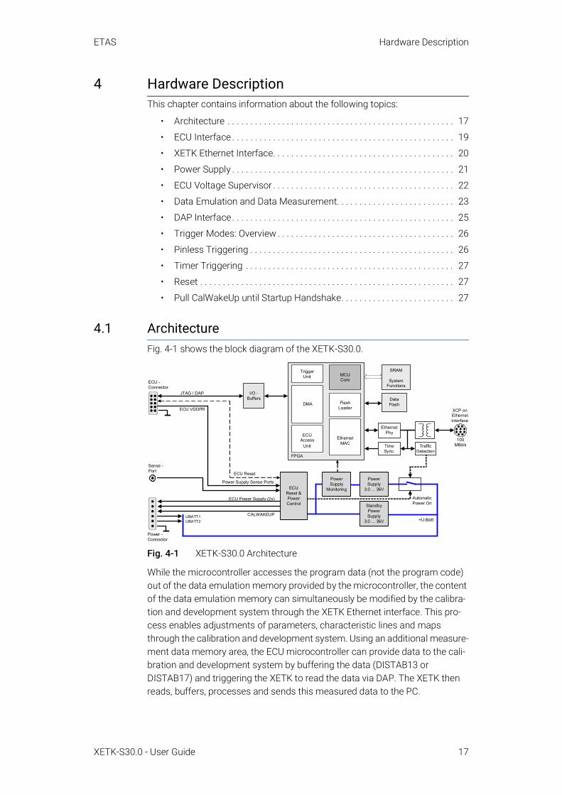
4.1 ArchitectureFig. 4-1 shows the block diagram of the XETK-S30.0.
Fig. 4-1 XETK-S30.0 Architecture
While the microcontroller accesses the program data (not the program code) out of the data emulation memory provided by the microcontroller, the content of the data emulation memory can simultaneously be modified by the calibra-tion and development system through the XETK Ethernet interface. This pro-cess enables adjustments of parameters, characteristic lines and maps through the calibration and development system. Using an additional measure-ment data memory area, the ECU microcontroller can provide data to the cali-bration and development system by buffering the data (DISTAB13 or DISTAB17) and triggering the XETK to read the data via DAP. The XETK then reads, buffers, processes and sends this measured data to the PC.
XCP onEthernetInterface
SRAM
SystemFunctions
TriggerUnit
100MBit/s
Automatic Power On
Power Supply Sense Ports
ECU Reset
DMA
MCUCore
EthernetMAC
FlashLoader
ECUAccess
Unit
DataFlash
ECU -Connector
TimeSync.
TrafficDetection
EthernetPhy
I/O -Buffers
FPGA
Power -Connector
Sense -Port
JTAG / DAP
ECU VDDPR
ECUReset & Power Control
Power Supply
Monitoring
Power Supply
3.0 ... 36V
StandbyPower Supply
3.0 ... 36V +U-BattUBATT1UBATT2
ECU Power Supply (2x)
CALWAKEUP

ETAS Hardware Description
XETK-S30.0 - User Guide 18
If no additional measurement data memory is available, the XETK-S30.0 can alternatively read the data to be measured directly from the microcontroller’s memory. This process is Triggered Direct Measurement (TDM) with DISTAB13 or DISTAB17.
The 100 Mbit/s XETK Ethernet interface provides communication with the PC.
ETK Connector DescriptionCON1 XETK Ethernet interface (ETAS module or PC)CON2 ECU InterfaceCON3 ECU EDRAM Sense portCON4 Power supply
ETAS Hardware Description
XETK-S30.0 - User Guide 19
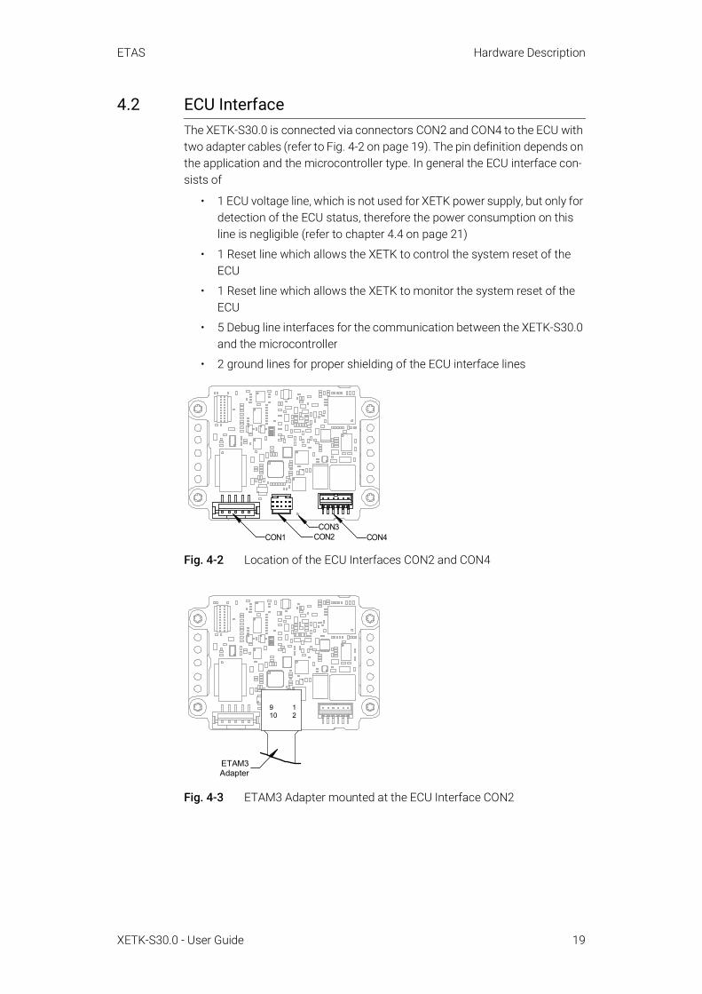
4.2 ECU InterfaceThe XETK-S30.0 is connected via connectors CON2 and CON4 to the ECU with two adapter cables (refer to Fig. 4-2 on page 19). The pin definition depends on the application and the microcontroller type. In general the ECU interface con-sists of
• 1 ECU voltage line, which is not used for XETK power supply, but only for detection of the ECU status, therefore the power consumption on this line is negligible (refer to chapter 4.4 on page 21)
• 1 Reset line which allows the XETK to control the system reset of the ECU
• 1 Reset line which allows the XETK to monitor the system reset of the ECU
• 5 Debug line interfaces for the communication between the XETK-S30.0 and the microcontroller
• 2 ground lines for proper shielding of the ECU interface lines
Fig. 4-2 Location of the ECU Interfaces CON2 and CON4
Fig. 4-3 ETAM3 Adapter mounted at the ECU Interface CON2
CON4CON1 CON2CON3
ETAM3Adapter
910
12

ETAS Hardware Description
XETK-S30.0 - User Guide 20
4.3 XETK Ethernet InterfaceThe XETK Ethernet interface can be directly connected to the PC via CON1 (refer to Fig. 4-4). No additional ETAS module is required for the access to the ECU.
The interface is a standard full duplex 100Base-TX Ethernet interface using the XCP protocol. The XETK Ethernet interface is integrated in the ETAS IP world with automatic IP management and supports the open automotive "Universal Measurement and Calibration" standard "XCP on Ethernet" (TCP/IP, UDP/IP). The open XCP on Ethernet interface allows for connecting to the XETK-S30.0 with third party application software.
Fig. 4-4 Location of the XETK Ethernet Interface connector (CON1)
NOTEThe XETK Ethernet interface is not compatible with the ETK interfaces in modules like e.g. ES910, ES590, ES591, ES592, ES593-D, ES595, ES1232-A. The XETK Ethernet interface is compatible with the ECU interface of the ES910 module and the Ethernet interfaces of the ES51x/ ES592/ ES593-D/ ES595/ ES600 modules.
NOTEPlease see chapter 7.1.2 on page 34 for additional information regarding PC requirements for the Ethernet interface.
CON1

ETAS Hardware Description
XETK-S30.0 - User Guide 21
4.4 Power SupplyThe XETK-S30.0 requires a permanent power supply. It is typically powered directly from the car battery. The input voltage may vary between 4.3 V and 36 V. In case of higher input voltages to the XETK, additional voltage protection is required. The XETK-S30.0 will also accept voltage dips down to 3 V, for a maximum duration of 15 ms (for additional details of low voltage operation, see ISO standard 16750)
From the input battery voltage, switch-mode power supplies provide all neces-sary voltages on the XETK-S30.0. The power supply of the ECU is not affected by the XETK-S30.0. An automatic switch ensures that the power supply of the XETK-S30.0 is automatically switched on and off when the XETK enters and leaves its standby (sleep) mode.
The XETK-S30.0 is supplied with power through the connector CON4.
Fig. 4-5 Location of the XETK-S30.0 Power Supply Connectors
CON4

ETAS Hardware Description
XETK-S30.0 - User Guide 22
4.5 ECU Voltage SupervisorThe ECU voltage (VDDP) is monitored by the XETK to recognize whether the ECU is switched on or off. Additionally the ECU RAM standby voltage (VDDS-BRAM) is monitored to determine if the standby RAM content is still valid. These two signals are only used for monitoring therefore the load current is negligible.
The XETK-S30.0 provides two possibilities to supply and supervise the ECU RAM standby voltage:
• The XETK-S30.0 monitors the VDDSBRAM supply on board the XETK. The microcontroller’s standby power supply pin must be connected to the XETK pin VDDSBRAM.
• At the through-hole solder pad CON3 the XETK-S30.0 can additionally monitor the VDDSBRAMsense voltage if it is provided by the ECU. The microcontroller’s standby power supply pin must be connected to the XETK pin VDDSBRAMsense. The microntroller’s standby power supply may be provided by the ECU or by the XETK.
NOTEThe XETK-S30.0 only allows switching between reference page and working page if there is a valid voltage at the sense pin and the working page has been initialized by the calibration and development system.

ETAS Hardware Description
XETK-S30.0 - User Guide 23
4.6 Data Emulation and Data MeasurementThe XETK-S30.0 is a serial XETK using DAP as the primary microcontroller interface. Typical of all serial (X)ETKs, the RAM used for data emulation and data measurement is not accessible by the XETK until the microcontroller is powered up and the startup handshake is performed.
Serial XETKs use the ETAS two page concept, consisting of both a Reference and a Working page.
The Reference Page is located in the ECU flash and can not be modified by a simple write access. All changes to the Reference Page must be done via Flash programming.
The Working Page is located within the microcontroller's ED RAM. The Working Page may be a portion of or the entire size of the ED RAM. The ED RAM used for the emulation of calibration data must not be used by the ECU software directly as general purpose RAM. It is recommended that the ED RAM is perma-nently powered by the XETK or ECU. The XETK/INCA has the complete control over the RAM used as Working Page and it's contents. When enabling data emulation, the XETK establishes a basic start-up configuration of the data in the Working Page by copying the corresponding data in the Flash to the emula-tion space.
4.6.1 Page SwitchingTo enable calibration, the Working Page must be activated. The process of switching from the Reference Page to the Working Page and vice versa is known as page switching. The XETK-S30.0 supports two methods of page switching; however one method is only available for certain controllers.
The XETK-S30.0 can access both the Reference Page and the Working Page, regardless of which is active from the microcontroller's point of view and which page switch method is used. The two types page switching methods are described next.
4.6.1.1 Protocol Based page switchingThe XETK-S30.0 supports Protocol Based page switching for all supported microcontrollers. Page switching is implemented in microcontroller software by switching the overlay memory on (Working Page) and off (Reference Page) using microcontroller overlay registers. The XETK-S30.0 does not directly con-trol the microcontroller overlay registers. Instead, the XETK-S30.0 and micro-controller software use a simple communication method with a shared mailbox in RAM. The XETK uses this mailbox to request and monitor page
NOTEWith serial ETK's such as the XETK-S30.0, there is an important restriction that no access to the memory is possible, while the ECU is not running. To enable a cold start measurement (measurement during ECU power-up) in spite of this restriction, the cold start measurement procedure is defined to give the user the feeling of a parallel XETK. Please inquire further if you would like additional details for the cold start measurement procedure.

ETAS Hardware Description
XETK-S30.0 - User Guide 24
switching; the microcontroller software is responsible to service this mailbox and perform the page switches. Using an overlay modification description, also in RAM, the XETK provides the necessary information of how the overlay regis-ters need to be modified to realize the page switch which is requested.
4.6.1.2 Direct Register Access page switchingThe XETK-S30.0 supports Direct Register Access page switching for microcon-trollers which provide additional internal registers for page switching. Switch-ing between the Reference Page and Working Page is done in microcontroller hardware by redirecting accesses to calibration data between either the Flash (Reference Page) or the RAM (Working Page) using microcontroller internal registers. The XETK-S30.0 has direct access to control these registers.
To use Direct Register Access page switching, the microcontroller software could initialize the necessary registers; however, it must not change the values after the XETK startup handshake has taken place.
NOTEThe XETK-S30.0 can use the Direct Register Access page switch method only with the TC39x-ED (B-Step) variant of the Aurix microcontrollers. Additional Aurix microcontrollers can be supported on request.
ETAS Hardware Description
XETK-S30.0 - User Guide 25
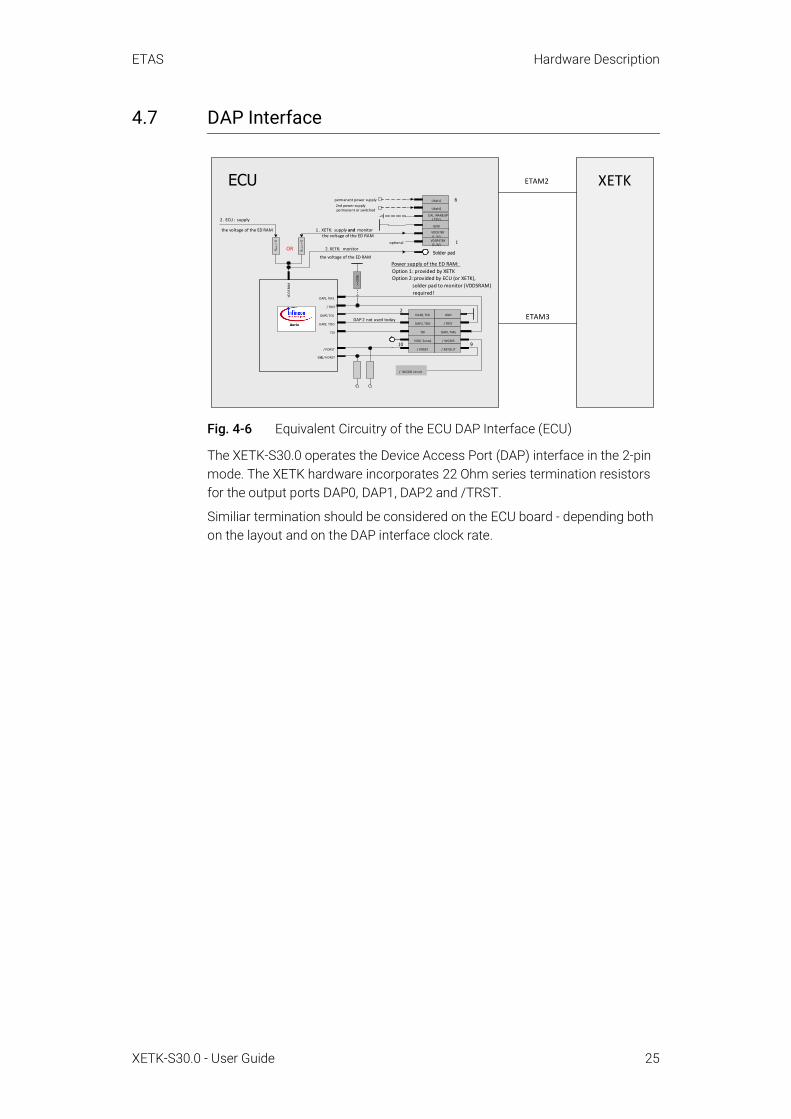
4.7 DAP Interface
Fig. 4-6 Equivalent Circuitry of the ECU DAP Interface (ECU)
The XETK-S30.0 operates the Device Access Port (DAP) interface in the 2-pin mode. The XETK hardware incorporates 22 Ohm series termination resistors for the output ports DAP0, DAP1, DAP2 and /TRST.
Similiar termination should be considered on the ECU board - depending both on the layout and on the DAP interface clock rate.
XETK
ETAM3
ETAM2
Aurix
/ TRST
DAP1, TMS
>=1
00k
Ubatt1
CAL WAKEUP(12V)
GND
ECU
DAP2; TDO / TRST
/ WGDIS
DAP0,TCK
TDI
DAP2, TDO
GND
DAP1,TMS
/ PORST
VDD ( Sense)
/ RSTOUT
DAP0,TCK
ESR0,/ HDRST
1
2
910
VDDSRA
M
TDI
the voltage of the ED RAM
RXET
K=0
RECU=0
the voltage of the ED RAM
OR
permanent power supply
the voltage of the ED RAM
Power supply of the ED RAM:
Option 1: provided by XETK
Option 2:provided by ECU (or XETK),
solder pad to monitor (VDDSRAM)
required!
Solder pad
/ WGDIS circuit
/ PORST
VDDSTBY
(1 ,3V)VDDPSTBY (3 ,3V)
Ubatt22nd power supplypermanent or switched
6
optional
DAP 2 not used today Aurix
2 . ECU: supply
1 . XETK: supply and monitor
2. XETK: monitor

ETAS Hardware Description
XETK-S30.0 - User Guide 26
4.8 Trigger Modes: OverviewThe XETK-S30.0 supports the following trigger modes:
• Pinless triggering
• Timer triggering
The trigger mode "Pinless Triggering" uses the microcontroller’s internal Devel-opment Trigger Semaphore (DTS) for triggering. See also chapter “Pinless Trig-gering” on page 26.
The trigger mode "Timer Triggering" uses four internal timers of the XETK for triggering. See also chapter “Timer Triggering” on page 27.
4.9 Pinless Triggering
4.9.1 Startup HandshakeThe COMDATA trigger register is used to generate an ETK startup handshake. The ECU must ensure that all memory ECC initializations have been completed prior to the start-up handshake.
4.9.2 XETK Trigger Generation
InitializationAfter the startup handshake and measurement is enabled, the XETK is waiting for triggers from the ECU software.
Application runningTo generate triggers, the ECU software sets bits in the trigger register "CBS_TRIG" by writing the associated bits in the trigger setting register "CBS_TRIGS".
Each bit of the trigger setting register "CBS_TRIGS" corresponds to a bit in the same position in the trigger register "CBS_TRIG", each of them corresponding to an XETK hardware trigger.
The XETK periodically polls the trigger register "CBS_TRIG" via IO_READ_TRIG for detecting triggers. The polling rate is determined by the fastest measure-ment raster and is configurable with a 50 µs default.
Active bits in trigger register "CBS_TRIG" are automatically cleared by the CPU when the register is read by the XETK-S30.0 via IO_READ_TRIG.For generating triggers, the ECU software sets bits in the trigger register "CBS_TRIG" by writing the associated bits in the trigger setting register "CBS_TRIGS".

ETAS Hardware Description
XETK-S30.0 - User Guide 27
4.10 Timer TriggeringThe trigger mode "Timer Triggering" uses four internal timers of the XETK-S30.0 for triggering. A fixed configurable period is used for triggering.
The time intervals between trigger events are in accordance with the config-ured timer values. This values and their resolution have to be defined in the A2L file. Available settings are:
• Minimum time interval 100 µs
• Maximum period duration 1 s
• Timer resolution 1 µs
The timers work in an asynchronous manner to the ECU.
4.11 ResetThe requirement for the XETK-S30.0 reset mechanism is to ensure that power-up and power-down behavior of ECU is clean and smooth.
The XETK-S30.0 normally drives /PORST low during XETK power up or upon INCA request. The signals /PORST and /ESR0 of the microcontroller are used by the XETK-S30.0 to detect when the ECU is in reset.
The XETK-S30.0 senses the switched ECU power supply. This allows it to detect when the ECU is off and forward this information to INCA. In addition, it allows the XETK to enter the power save mode with the calibration system unplugged.
4.12 Pull CalWakeUp until Startup HandshakeThe XETK has the ability to wake up the ECU by applying voltage to the Cal-WakeUp pin of the ECU connector. This allows the XETK to configure a mea-surement while the ECU is off.
When waking up the ECU via the CalWakeUp pin, it can be configured if the pin is driven high until the microcontroller core voltage (VDDP) is high or if the pin should be driven high until the start-up handshake between ECU and XETK is complete.

ETAS Installation
XETK-S30.0 - User Guide 28
5 InstallationThis chapter contains information about the following topics:
• Connection to the ECU . . . . . . . . . . . . . . . . . . . . . . . . . . . . . . . . . . . . . . . . . 28
• Wiring . . . . . . . . . . . . . . . . . . . . . . . . . . . . . . . . . . . . . . . . . . . . . . . . . . . . . . . 30
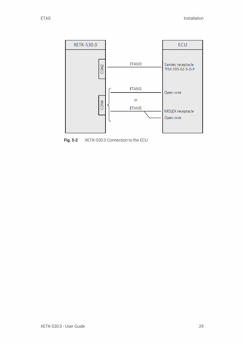
5.1 Connection to the ECU
For connecting the XETK-S30.0 to the ECU two XETK adapter cables are rec-ommended:
• at CON2 adapter ETAM3
• at CON4 adapter ETAM2 or ETAM5
Adapter cables ETAM2, ETAM5, ETAM9, ETAM10, and ETAM12 are also avail-able. The adapter cables are to be ordered separately (refer chapter “Ordering Information” on page 74).
The suitable connectors SAMTEC-10 (CON2) and MOLEX-6 (CON4) should have been populated onto the ECU PCB for adapters ETAM3 and ETAM2/ ETAM5 (see Fig. 5-2 for additional connector details).
Fig. 5-1 XETK-S30.0 Connection to the ECU
CAUTIONSome components of the interface board may be damaged or destroyed by electrostatic discharges. Please keep the board in its storage package until it is installed. The board should only be taken from its package, configured, and installed at a work place that is protected against static discharge.
CAUTIONRisk of short circuiting the internal signals of the XETK!When you mount the XETK to the ECU, you must ensure that the screws and washers used will not penetrate the XETK printed circuit board.
ETAM2/ ETAM5
XETK-S30.0
ETAM3
ETAS Installation
XETK-S30.0 - User Guide 29
Fig. 5-2 XETK-S30.0 Connection to the ECU

ETAS Installation
XETK-S30.0 - User Guide 30
5.2 Wiring
5.2.1 XETK Ethernet Interface
Fig. 5-3 Wiring - XETK Ethernet Interface
The XETK Ethernet interface can be directly connected to the PC. No additional ETAS module is required for the access to the ECU.
NOTEThe XETK Ethernet interface is compatible with the Ethernet interfaces of the ES51x/ES59x/ES600/ES8xx/ES910 module.
PC
ES910
PC
C B E 200 -3
C B AE 200 .2-1 m20
C B AE 330 .2-0 m5
Lem o10 (f)
Lem o10 ( f)
Lem o10 ( f) R J45
Lem o8 (m )
Lem o10 (m) R J45
ES51x
ES51 x
C B E 230 .1 -3C B E 230 .1 -8
Lem o10 (m )
Lem o10 (m )XETK
C B AM 230 .1-0m 38C B A M 240 .1-0 m6C B A M 270 .1-0 m5C B A M 271 .1-0 m5
ES5 9x
ES600
ES89x

ETAS Installation
XETK-S30.0 - User Guide 31
5.2.2 Power Supply The XETK-S30.0 needs a permanent power supply (refer chapter “Power Sup-ply” on page 21). Refer to figures Fig. 5-4, Fig. 5-5, or Fig. 5-6 for recommenda-tions on permanent power supply connection.
Permanent Power Supply inside ECU available
Fig. 5-4 Permanent Power Supply inside ECU available
Permanent Power Supply inside ECU not available
Fig. 5-5 Permanent Power Supply inside ECU not available
Isolated Power Supply inside ECUThe XETK-S30.0 does not require a galvanically isolated power supply. For spe-cial applications ETAS offers the isolated power supply ETP2.
Fig. 5-6 Isolated Power Supply inside ECU
ECU
12V
ECU GND
Permanent Supply
ECUConnector
ETK
ca.
36 V
Power Supply Connector
Vehicle
Battery
Vehicle Wiring
Cable ETAM2
ECU
Ignition Key
12V
ECU GND
Permanent Supply
12V
ECUConnector
Cable K70
ETK
ca.
36 V
Power Supply Connector
Vehicle
Battery
Vehicle Wiring
Cable KA50 or CBAM270 (power line)
Cable ETAM2
ECU
12V
Permanent Supply
ECUConnector
4,8V… 36V
Input
Output
12 V-
++
-
ETK
ca.
36 V
Power Supply Connector
Vehicle
Battery
Vehicle Wiring
CableETAM2
andCBM200
Cable ETAM2
Isolated Power Supply

ETAS XETK Configuration
XETK-S30.0 - User Guide 32
6 XETK ConfigurationThis chapter contains information about the following topics:
• Overview . . . . . . . . . . . . . . . . . . . . . . . . . . . . . . . . . . . . . . . . . . . . . . . . . . . . . 32
• Configuration Parameter . . . . . . . . . . . . . . . . . . . . . . . . . . . . . . . . . . . . . . . 33
6.1 OverviewAs already mentioned in previous chapters, some project-specific adjustments are necessary. Configuration data is stored permanently in a serial Flash.
Generating a valid configuration data set is supported by the "(X)ETK Configu-ration Tool" (XCT Tool). The XCT Tool contains information on all available XETKs. The user is supported through a graphical interface.
The configuration is done in two steps:
1. Generation of the special address offset for the emulation and measurement data memory.
The location of data areas, measured data output areas, trig-ger segment addresses etc. are familiar to the ECU software developer, or can be generated automatically. If an ECU description database (ASAP, ...) with the corresponding input exists, these inputs can be downloaded from this database. If necessary, a plausibility check is performed.
2. Connection of the XETK to the ECU.
The ECU hardware developer defines the connection of the XETK to the ECU. The corresponding signals usually have to be adjusted for each microcontroller. All inputs are checked for plausibility, to make sure that a valid configuration is gener-ated.
The "(X)ETK Configuration Tool" can create the following output:
• Direct XETK configuration
• Storage of the configuration in a data file
• The corresponding ASAP2 input
The most important outputs are the entries for the ASAP2 file. All A2L defini-tions necessary for configuring an ETK will be created. These are:
• Overlay Region definitions
• Memory Segment definitions
• XETK configuration features
• Raster definitions
If these parameters are entered correctly in the corresponding ECU description file, it guarantees that every time the calibration system is started, the XETK is checked for the appropriate configuration. If necessary, the XETK will be con-figured appropriately to the corresponding project.

ETAS XETK Configuration
XETK-S30.0 - User Guide 33
6.2 Configuration ParameterThe XCT Tool provides support concerning hardware configuration parameters and their possible values.
They are described for the different (X)ETK types in the help document of the "(X)ETK Configuration Tool".
Starting the "XCT Tool" help 1. Start the XCT Tool.
The main window of the XCT tool opens.
2. Select in the menu bar ? Contents.
The XCT Tool help window opens.
3. Choose Reference to User Interface (X)ETK Hardware Configuration Parameters.
4. Choose the topic XETK-S30.0.
> The topic XETK-S30.0 contains information about the XETK-S30.0 hardware configuration parameters and their possible values.

ETAS Technical Data
XETK-S30.0 - User Guide 34
7 Technical DataThis chapter contains information about the following topics:
• System Requirements . . . . . . . . . . . . . . . . . . . . . . . . . . . . . . . . . . . . . . . . . 34
• Data Emulation and Measurement Memory . . . . . . . . . . . . . . . . . . . . . . 36
• Configuration . . . . . . . . . . . . . . . . . . . . . . . . . . . . . . . . . . . . . . . . . . . . . . . . . 36
• XETK Ethernet Interface . . . . . . . . . . . . . . . . . . . . . . . . . . . . . . . . . . . . . . . 37
• Environmental Conditions . . . . . . . . . . . . . . . . . . . . . . . . . . . . . . . . . . . . . . 37
• Power Supply . . . . . . . . . . . . . . . . . . . . . . . . . . . . . . . . . . . . . . . . . . . . . . . . 38
• Microcontroller Interface . . . . . . . . . . . . . . . . . . . . . . . . . . . . . . . . . . . . . . . 39
• Test Characteristics . . . . . . . . . . . . . . . . . . . . . . . . . . . . . . . . . . . . . . . . . . . 39
• DAP Timing Characteristics . . . . . . . . . . . . . . . . . . . . . . . . . . . . . . . . . . . . 40
• Electrical Characteristics . . . . . . . . . . . . . . . . . . . . . . . . . . . . . . . . . . . . . . . 41
• Pin Assignment . . . . . . . . . . . . . . . . . . . . . . . . . . . . . . . . . . . . . . . . . . . . . . . 42
• Mechanical Dimensions. . . . . . . . . . . . . . . . . . . . . . . . . . . . . . . . . . . . . . . . 45
7.1 System Requirements
7.1.1 ETAS Compatible HardwareES592, ES593-D, ES595, ES600, ES8xx, ES910
7.1.2 PC with one Ethernet InterfaceA PC with one open Ethernet interface (1 Gbit/s or 100 Mbit/s, full duplex) with RJ-45 connection is required. Ethernet interfaces that are implemented with an additional network card in the PC must feature a 32-bit data bus.
Requirement to ensure successful Initialization of the Module
To deactivate the Power saving ModeChoose in Windows System Control Center / Device Manager / Network Adapter the used network adapter by double-click. Deactivate the "Allow the computer to turn off this device to save power" option in the "Power Manage-ment" register. Confirm your configuration. The manufacturers of network adapter have different names for this function.
NOTEHalf Duplex mode and Half Duplex Ethernet interfaces are not supported.
NOTEIt is imperative you disable the function which automatically switches to power-saving mode on your PC network adapter when there is no data traffic on the Ethernet interface!

ETAS Technical Data
XETK-S30.0 - User Guide 35
Example:
• "Link down Power saving"
• "Allow the computer to turn off this device to save power"
7.1.3 Software SupportYou need following software versions to support the XETK-S30.0:
7.1.3.1 Use case: Measurement & Calibration, ECU Flash Programming
7.1.3.2 Use case: Rapid Prototyping
NOTEOperating the XETK-S30.0 with older software versions is not possible.
Microcontroller HSP INCA INCA-MCE ETK ToolsTC23x-PD V11.10.0 V7.2.10 V7.2.10 V4.1.11TC26x-PD V11.2.0 V7.2.2 V2.0 V4.1.3TC26x-ED V11.2.0 V7.2.2 V2.0 V4.1.3TC27x-PD V11.2.0 V7.2.2 V2.0 V4.1.3TC27x-ED V10.9.0 V7.1.9 V2.0 V4.0.5TC29x-ED V10.9.0 V7.1.9 V2.0 V4.0.5TC29x-PD V11.8.0 V7.2.8 V7.2.8 V4.1.9TC33x-PD V12.0.0 V7.3.0 V7.3.0 V4.2.0TC36x-PD V11.15.0 V7.2.15 V7.2.15 V4.1.16TC37x-ED V11.12.0 V7.2.12 V7.2.12 V4.1.13TC37x-PD V11.15.0 V7.2.15 V7.2.15 V4.1.16TC38x-PD V11.8.0 V7.2.8 V7.2.8 V4.1.9TC39x-ED (A-Step) V11.2.1 V7.2.2 V2.0 V4.1.3TC39x-ED (B-Step) V11.8.0 V7.2.8 V7.2.8 V4.1.9TC37x-XX V12.3.0 V7.3.3 V7.3.3 V4.2.3TC39x-XX V12.3.0 V7.3.3 V7.3.3 V4.2.3
Îtem DescriptionSupported microcontroller All microcontrollers listed in chapter
7.1.3.1 on page 35ASCET-RP V6.4INTECRIO V4.6Supported Bypass methods Service Based Bypass SBB V2.1
NOTEThe XETK-S30.0 supports the bypass procedure with DISTAB17. Classical Hook Based Bypass (HBB) method is not supported. This can be realized via "Hooked Service Points" (with the help of a SBB Service Point and DISTAB17).

ETAS Technical Data
XETK-S30.0 - User Guide 36
7.2 Data Emulation and Measurement Memory
7.2.1 Data Emulation Memory and Microcontroller SupportThe XETK-S30.0 uses a portion of or up to the entire size of the ED RAM, to emulate data in internal flash. The following table lists the supported microcon-trollers, the size of the ED RAM, and states if the ED RAM is capable of being powered using a standby supply.
7.2.2 Measurement Data Memory
7.3 Configuration
Microcontroller Max. ED RAM Standby poweredTC26x-ED 0.5 MByte YesTC27x-ED 1 MByte YesTC29x-ED 2 MByte YesTC37x-ED 4 MByte YesTC39x-ED 4 MByte Yes
Item CharacteristicsLocation Typically located within the emulation
memory when using DISTAB13 or DISTAB17 hooks. Measurement data memory can be located in internal RAM if the entire ED RAM is needed for calibration.
Item CharacteristicsConfiguration Typically located within the emulation
memory when using DISTAB13 hooks. Measurement data memory can be located in internal RAM if EMEM is needed for calibration.
Update Logic devices updated using HSP software

ETAS Technical Data
XETK-S30.0 - User Guide 37
7.4 XETK Ethernet Interface
7.5 Environmental Conditions
Item CharacteristicsConnection • 100 Mbit/s Ethernet, Full Duplex
• PC Card 32 bitProtocol XCP on TCP/IP or UDP/IPIP address • Dynamic (standard, for INCA) or
• Static (e.g. for Rapid Prototyping) by using the XETK Configuration Tool (default IP address: 192.168.40.16)
Cable length max. 30 m / 100 ftEthernet Interface DC decoupling
NOTETo ensure successful initialization of the network card of your PC, refer to chapter 7.1.2 on page 34
Item CharacteristicsTemperature range (operation) - 40 °C to +110 °C/ - 40 °F to +230 °FTemperature range (storage) 0 °C to +50 °C/ - 18 °F to +122 °FRelative humidity (non-condensing) 0 to 95%Operating altitude max. 5000 m/ 16400 ftContamination level 2Degree of protection Determined by installation in ECUOvervoltage category (AC mains supply)
II

ETAS Technical Data
XETK-S30.0 - User Guide 38
7.6 Power Supply
Parameter Symbol Condition Min Typ Max UnitPermanent power supply (car battery)
UBatt Vehicle usage 1) 4.3 12 36 V[all values ±0%]
Cranking voltage UBatt < 3 seconds 3 VStandby current ISTBY UBatt = 12 V;
ECU off; no load from ECU; T = 20 °C
15 28 40 mA
Operating current IBatt UBatt = 12 V; no load from ECU; T = 20 °C
70 135 250 mA
Power dissipation PBatt UBatt = 12 V; I = 0 mA at pin ECU_SBRAM; T = 20 °C
1.62 W
Power dissipation PBatt UBatt = 12 V; I = 500 mA at pin VDDSTBY; I = 80 mA at pin VDDPSTBY; T = 20 °C
3 W
1) The XETK-S30.0 implements reverse voltage protection in the same range and may be used only with central load dump protection. 24 V vehicles require UBatt disturbing pulse reduction to 12 V vehicle system. 12 V vehicles don’t require special disturbing pulse reductions.
NOTEThe XETK-S30.0 will accept permanent power supply voltage dips (for addi-tional details of 3 V low voltage operation, see ISO standard 16750).

ETAS Technical Data
XETK-S30.0 - User Guide 39
7.7 Microcontroller Interface
7.8 Test Characteristics
Symbol Condition Min Typ Max UnitECU Standby RAM Output Volt-age
VDDSTBY max 500 mA load 1.23 1.3 1.34 V
VDDPSTBY Output Voltage
VDDP-STBY
max 80 mA load 3.14 3.3 3.46 V
Cal_Wakeup Output Voltage
CAL_WAKEUP
UBatt = 6 - 36 V; load = 0 - 50 mA
UBatt-1V UBatt V
ECU Power Sup-ply Supervision Voltage (3.3 V selected)
VDDP ECU on 2.48 2.58 2.68 VECU off 2.33 2.43 2.53 V
IDDP VDDP 3.3 V 200 A
ECU Power Sup-ply Supervision Voltage (5.0 V selected)
VDDP ECU on 2.98 3.08 3.18 VECU off 2.83 2.93 3.03 V
IDDP VDDP 5.0 V 300 A
ECU Standby RAM Supervision Voltage
VDDSTBY /VDDST-BY_SENSE
VDDSTBY 1.02 1.12 1.22 VVDDSTBY 1 1.1 1.2 V
IDDSTBY VDDSTBY 1.30 V 77 A
Parameter Symbol Condition Min Typ Max UnitReset delay 1 1) tReset1 UBatt = 12 V
VDDP = 0 V 3.3 V/5.0 V without transferring FPGA
17 33 ms
Reset delay 2 2) tReset2 UBatt = 0 V 12 V transfer FPGA
200 340 ms
1) Delay of ECU reset through ETK without transferring the FPGA (UBatt present, VDDP will be switched on)2) max. delay of ECU reset through ETK (UBatt and VDDP will be switched on)

ETAS Technical Data
XETK-S30.0 - User Guide 40
7.9 DAP Timing CharacteristicsThe following diagrams show the timings the XETK-S30.0 can process.
7.9.1 DAP Timing Diagram
7.9.2 DAP Timing Diagram DAP Timing Parameter
NOTEDAP timing parameters in this chapter refer to the DAP interface (CON2) of the XETK-S30.0. The DAP wiring to the ECU (ETAM2) must be taken account additionally. All timings are measured at a reference level of 1.5 V. Output signals are mea-sured with 20 pF to ground and 50 to 1.5 V.
Parameter Symbol Value [ns] CommentDAP0 Clock Period (ETK --> Target)
tCLK 10 100 MHz DAP Clock Fre-quency
20 50 MHz DAP Clock Fre-quency
DAP1 Set-Up Time (ETK --> Target)
tSU 4
DAP1 Hold Time (ETK --> Target)
tH 2
DAP1 Clock-to-Out Time (Target --> ETK)
tCO ~ Undetermined, ETK auto-matically determines optimum sampling point
DAP1 Valid Window (Target --> ETK)
tValid 8
DAP0_(ETK)
DAP1_(ETK)
DAP1_(ECU)
tSU tH
tValid
tCLK
tCO

ETASTechnical Data
XETK-S30.0 - User Guide
41
7.10 Electrical Characteristics
7.10.1 ECU Interface Connector
Signal Pin Type VOL (max) [V]
VOH (min) [V]
VOH (max) [V]
VIL (max) [ V]
VIH (min) [V]
VIH (max) [V]
Leakage current (min) / (max) [A]
Additional load by ETK 1) (typ) [pF]
DAP0 XO 2) 0.7 2.3 3.3 - - - +3340 / +2360 15DAP1 IXO 2) 0.7 2.3 3.3 0.8 2 5.5 +3340 / +2360 15DAP2 IXO 2) 0.7 2.3 3.3 0.8 2 5.5 +40 / -40 15Reserved XO 2) 0.7 2.3 3.3 - - - +20 / -20 10/TRST XO 2) 0.7 2.3 3.3 - - - +20 / -20 10/ESR0 IXOD 3) 0.7 - - 0.8 2 5.5 +25 / -20 22/PORST IXOD 3) 0.7 - - 0.8 2 5.5 +25 / -20 22WGDIS XO 2) 0.7 2.3 3.3 - - - +20 / -20 10 Pin Type: I: Input, X: Tristate, O: Output, OD: Open Drain
1) Adapter cable and Samtec connector not considered; PCB 1 pF/cm 2) max 12 mA 3) max 0.2 A

ETAS Technical Data
XETK-S30.0 - User Guide 42
7.11 Pin Assignment
7.11.1 XETK-S30.0 Interface Location
Fig. 7-1 XETK-S30.0 Interface Location
7.11.2 XETK Ethernet Interface Connector CON1
Fig. 7-2 XETK Ethernet Interface Connector CON1 Location
The interface is a standard full duplex 100Base-TX Ethernet interface using the XCP protocol.
CON4CON1 CON2CON3
CON1

ETAS Technical Data
XETK-S30.0 - User Guide 43
7.11.3 ECU Interface Connector CON2
Fig. 7-3 ECU Interface Connector CON2 Location
7.11.4 VDDSTBY_SENSE Connector CON3
Fig. 7-4 VDDSTBY_SENSE Connector CON3 Location
Pin Signal Direction Comment1 DAP0 Output DAP signal2 GND Power Signal Ground3 /TRST Output DAP signal4 DAP2 Bidir DAP signal5 WDGIS Output Watchdog disable Signal6 DAP1 Bidir DAP signal7 RESERVED Output DAP signal8 VDDP (Sense) Input Sense for Switched power supply of
ECU (ignition)9 /ESR0 Bidir ECU Reset signal (open drain) for Reset
assertion and supervision10 /PORST Bidir ECU Power On Reset signal (open drain)
for Reset assertion and supervision
Pin Signal Direction Comment1 VDDSTBY_-
SENSEInput ECU EDRAM Sense Pin
CON2
CON3

ETAS Technical Data
XETK-S30.0 - User Guide 44
7.11.5 Power Supply Connector CON4
Fig. 7-5 Power Supply Connector CON4 Location
Pin Signal Direction Comment1 VDDPSTBY
(3.3 V supply)Output Permanent power supply of ECU DAP
Interface, 3.3 V2 VDDSTBY
(1.30 V supply)Output Permanent power supply of ECU
EDRAM, 1.30 V3 GND Input Power GND4 CalWakeup Output Switch to Ubatt. ECU wake-up signal
(for measurement preparation)5 Ubatt2 Input Vehicle battery6 Ubatt1 Input Vehicle Battery
NOTEVDDSTBY may not be used as power supply of the microcontroller core. VDDSTBY is permanently available and must be used as power supply of the EDRAM, only.
CON4

ETAS Technical Data
XETK-S30.0 - User Guide 45
7.12 Mechanical DimensionsThe reference measure for all drawings is millimeters.
7.12.1 Top View
Fig. 7-6 XETK-S30.0 Dimensions - Top View (1)
Item Dimension [Millimeters]
Tolerance [Millimeters]
Dimension [Inches]
Tolerance [Inches]
A 45.00 +/- 0.20 1.772 +/- 0.008B 36.90 +/- 0.20 1.453 +/- 0.008C 23.30 +/- 0.20 0.917 +/- 0.008D 7.10 +/- 0.20 0.280 +/- 0.008E 48.25 +/- 0.20 1.900 +/- 0.008F 51.00 +/- 0.20 2.008 +/- 0.008G 3.25 +/- 0.10 0.128 +/- 0.004H 6.00 +/- 0.20 0.236 +/- 0.008I 3.50 +/- 0.10 0.138 +/- 0.004J 6.75 +/- 0.20 0.266 +/- 0.008K 10.00 +/- 0.20 0.394 +/- 0.008L 30.00 +/- 0.20 1.181 +/- 0.008M 33.25 +/- 0.20 1.309 +/- 0.008N 36.50 +/- 0.20 1.437 +/- 0.008P 40.00 +/- 0.20 1.575 +/- 0.008

ETAS Technical Data
XETK-S30.0 - User Guide 46
Fig. 7-7 XETK-S30.0 Dimensions - Top View (2)
7.12.2 Side View
Fig. 7-8 XETK-S30.0 Dimensions - Side View
Item Dimension [Millimeters]
Tolerance [Millimeters]
Dimension [Inches]
Tolerance [Inches]
A 48.25 +/- 0.20 1.900 +/- 0.008B 51.00 +/- 0.20 2.008 +/- 0.008C 3.25 +/- 0.10 0.128 +/- 0.004D 6.00 +/- 0.20 0.236 +/- 0.008E 3.50 +/- 0.10 1.900 +/- 0.004F 6.75 +/- 0.20 0.266 +/- 0.008G 12.25 +/- 0.20 0.482 +/- 0.008H 15.85 +/- 0.20 0.624 +/- 0.008I 20.00 +/- 0.20 0.787 +/- 0.008J 23.95 +/- 0.20 0.943 +/- 0.008K 27.55 +/- 0.20 1.085 +/- 0.008L 33.25 +/- 0.20 1.309 +/- 0.008M 36.50 +/- 0.20 1.437 +/- 0.008N 40.00 +/- 0.20 1.575 +/- 0.008
Item Dimension [Millimeters]
Tolerance [Millimeters]
Dimension [Inches]
Tolerance [Inches]
A 3.70 +/- 0.10 0.146 +/- 0.004B 1.50 +/- 0.16 0.059 +/- 0.006C 6.60 +/- 0.10 0.260 +/- 0.004

ETAS Cables and Accessories
XETK-S30.0 - User Guide 47
8 Cables and Accessories
8.1 Overview and ClassificationThis chapter contains information about the following cables and accessor
• Overview and Classification . . . . . . . . . . . . . . . . . . . . . . . . . . . . . . . . . . . . 47
• Requirements for failsafe Operation . . . . . . . . . . . . . . . . . . . . . . . . . . . . 47
• CBAM230 Cable . . . . . . . . . . . . . . . . . . . . . . . . . . . . . . . . . . . . . . . . . . . . . . 48
• CBAM240 Cable . . . . . . . . . . . . . . . . . . . . . . . . . . . . . . . . . . . . . . . . . . . . . . 50
• CBAM271 Cable . . . . . . . . . . . . . . . . . . . . . . . . . . . . . . . . . . . . . . . . . . . . . . 52
• ETAM2 ECU Adapter. . . . . . . . . . . . . . . . . . . . . . . . . . . . . . . . . . . . . . . . . . . 53
• ETAM3 ECU Adapter. . . . . . . . . . . . . . . . . . . . . . . . . . . . . . . . . . . . . . . . . . . 54
• ETAM5 ECU Adapter. . . . . . . . . . . . . . . . . . . . . . . . . . . . . . . . . . . . . . . . . . . 56
• ETAM9 ECU Adapter. . . . . . . . . . . . . . . . . . . . . . . . . . . . . . . . . . . . . . . . . . . 58
• ETAM10 ECU Adapter . . . . . . . . . . . . . . . . . . . . . . . . . . . . . . . . . . . . . . . . . 59
• ETAM12 ECU Adapter . . . . . . . . . . . . . . . . . . . . . . . . . . . . . . . . . . . . . . . . . 61
• CBE200 Cable . . . . . . . . . . . . . . . . . . . . . . . . . . . . . . . . . . . . . . . . . . . . . . . . 63
• CBAE200 Cable . . . . . . . . . . . . . . . . . . . . . . . . . . . . . . . . . . . . . . . . . . . . . . . 64
• CBE230 Cable . . . . . . . . . . . . . . . . . . . . . . . . . . . . . . . . . . . . . . . . . . . . . . . . 65
• CBAE330 Cable . . . . . . . . . . . . . . . . . . . . . . . . . . . . . . . . . . . . . . . . . . . . . . . 66
• CBAM270 Cable . . . . . . . . . . . . . . . . . . . . . . . . . . . . . . . . . . . . . . . . . . . . . . 67
• K70.1 Cable . . . . . . . . . . . . . . . . . . . . . . . . . . . . . . . . . . . . . . . . . . . . . . . . . . 70
• KA50 Cable. . . . . . . . . . . . . . . . . . . . . . . . . . . . . . . . . . . . . . . . . . . . . . . . . . . 72
8.2 Requirements for failsafe Operation
NOTESee chapter “Connection to the ECU” on page 28 for details on wiring the ECU interface adapters.
NOTEWe recommend to use ETAS cables or any other cables certified by the stan-dards for the application. Adhere to the maximum permissible cable lengths!
NOTEApplication-specific cables are available from ETAS. Please contact your ETAS contact partner or e-mail [email protected].
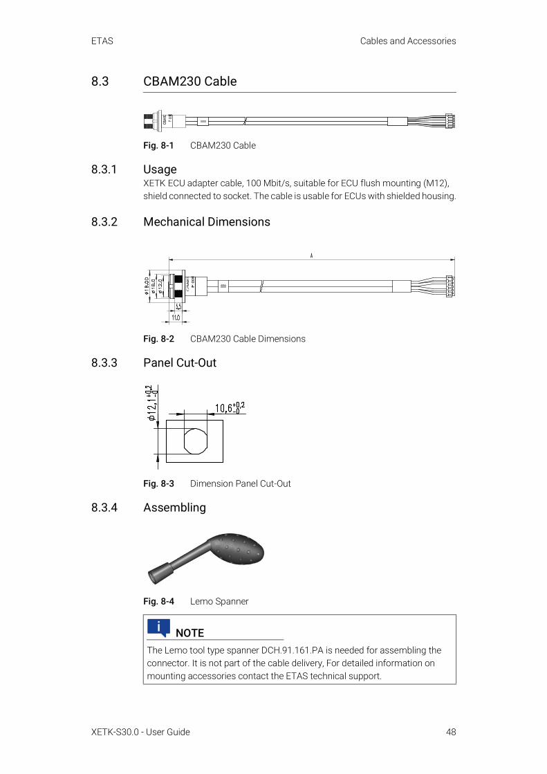
ETAS Cables and Accessories
XETK-S30.0 - User Guide 48
8.3 CBAM230 Cable
Fig. 8-1 CBAM230 Cable
8.3.1 UsageXETK ECU adapter cable, 100 Mbit/s, suitable for ECU flush mounting (M12), shield connected to socket. The cable is usable for ECUs with shielded housing.
8.3.2 Mechanical Dimensions
Fig. 8-2 CBAM230 Cable Dimensions
8.3.3 Panel Cut-Out
Fig. 8-3 Dimension Panel Cut-Out
8.3.4 Assembling
Fig. 8-4 Lemo Spanner
NOTEThe Lemo tool type spanner DCH.91.161.PA is needed for assembling the connector. It is not part of the cable delivery, For detailed information on mounting accessories contact the ETAS technical support.

ETAS Cables and Accessories
XETK-S30.0 - User Guide 49
8.3.5 Temperature Range
8.3.6 Ordering Information
Condition Temperature RangeOperating temperature -40 °C to +125 °C
Order Name Short Name Order NumberXETK ECU Adapter Cable, 100 Mbit/s, Shield on ECU-Housing, Lemo 1B HME - JST PHE (10fc-5fc), 0m38
CBAM230.1-0m38
F 00K 105 791

ETAS Cables and Accessories
XETK-S30.0 - User Guide 50
8.4 CBAM240 Cable
Fig. 8-5 CBAM240 Cable
8.4.1 UsageXETK ECU adapter cable, 100 MBit/s, shield connected to ECU housing (lead-through diameter for cable: 10 mm), 0.6 m length, shield bare for cable gland, isolated to the XETK. The cable is usable for ECUs with shielded housing.
8.4.2 Mechanical Dimensions
Fig. 8-6 CBAM240 Cable Dimensions
8.4.3 Mounting Proposal with an EMC safe Cable Gland
Fig. 8-7 Long Thread

ETAS Cables and Accessories
XETK-S30.0 - User Guide 51
Fig. 8-8 Short Thread
8.4.4 Temperature Range
8.4.5 Ordering Information
Remark in Fig. 8-7,Remark in Fig. 8-8
Mounting Material
*1 SKINTOP compact screwing; Manufacturer: Lapp; Description: MS-SC 11; Order-No.: 5311 2320 (long thread) or 5311 2220 (short thread)
*2 Nut for compact screwing; Manufacturer: Lapp; Descrip-tion: SM-PE 11; Order-No.: 5210 3220
NOTECable glands are not part of the CBAM240 cable delivery.
Condition Temperature RangeOperating temperature -40 °C to +125 °C
Order Name Short Name Order NumberXETK ECU Adapter cable, 100 Mbit/s, Lemo 1B HME - JST PHE (10fc-5fc), 0m6
CBAM240.1-0m6 F 00K 105 792

ETAS Cables and Accessories
XETK-S30.0 - User Guide 52
8.5 CBAM271 Cable
Fig. 8-9 CBAM271 Cable
8.5.1 Usage100 Mbit/s XETK ECU adapter cable, pre-assembled into PG9 screwing, shield on ECU housing, Lemo 1B PHE - JST PHR (10fc-5fc), 0m50
8.5.2 Mechanical Dimensions
Fig. 8-10 CBAM271 Cable Dimensions
8.5.3 Mounting
8.5.4 Temperature Range
8.5.5 Ordering Information
NOTEFor mounting the CBAM271 cable, cut a PG9 thread into the ECU housing. For thin walled housings use a nut SM-PE 9. Available from Lapp, Order number: 52103210.
NOTECable glands are not part of the CBAM271 cable delivery.
Condition Temperature RangeOperating temperature -40 °C to +125 °C
Order Name Short Name Order NumberXETK ECU Adapter Cable, pre-assembled into PG9 screwing, shield on ECU- Hous-ing, Lemo 1B PHE - JST PHR (10fc-5fc), 0m50
CBAM271.0-0m5 F 00K 107 867

ETAS Cables and Accessories
XETK-S30.0 - User Guide 53
8.6 ETAM2 ECU Adapter
Fig. 8-11 FETK/ XETK - ECU Adapter ETAM2
8.6.1 Pin Assignment
Fig. 8-12 ETAM2 Connector
8.6.2 ECU Signals
8.6.3 Ordering Information
Pin Color Signal Description1 Blue VDDPSTBY
(Supply)Permanent power to supply ECU interface (optional)
2 Yellow VDDSTBY (Supply)
Permanent power to supply ECU ED-RAM
3 Brown GND Power ground4 Green CAL_Wakeup Switch to Ubatt. ECU wake-up signal (for
measurement preparation)5 Red SGUBATT2 Car battery6 Red SGUBATT1 Car battery
Order Name Short Name Order NumberETAM2 XETK/FETK ECU Adapter, MOLEX - open wires (6fc - 6c), 0m25
ETAM2 F 00K 109 306

ETAS Cables and Accessories
XETK-S30.0 - User Guide 54
8.7 ETAM3 ECU Adapter
Fig. 8-13 ETAM3 ECU Adapter
8.7.1 UsageThe ETAM3 adapts a ECU with an 10 pin SAMTEC TFM-105 connector to an ETK. The ETABR3 cable requires on the ECU side an 10 pin SAMTEC connector (e.g. TFM-105-02-S-D-P).
8.7.2 Mechanical Dimensions
Fig. 8-14 ETAM3 Adapter (top view)
Fig. 8-15 ETAM3 Adapter (side view)
8.7.3 Pin Assignment
Fig. 8-16 ETAM3 Adapter (pin numbering)
NOTEPlease note that the ETAM3 flex foil has an minimum bending radius of 3 mm.

ETAS Cables and Accessories
XETK-S30.0 - User Guide 55
8.7.4 ECU Signals
8.7.4.1 JTAG and DAP Mode
/TRST Signal CharacteristicsA buffer in the /TRST line increases the signal-noise ratio in this line. It is sup-plied by the VDD(Sense) voltage.
/TRST Buffer Supply
/TRST Output Signal
8.7.5 Temperature Range
8.7.6 Ordering Information
NOTELFAST mode is not possible with the ETAM3 adapter.
Pin JTAG Mode DAP Mode1 GND GND2 TCK DAP03 /TRST /TRST4 TDO DAP25 TMS DAP16 TDI -7 WDGDIS WDGDIS8 VDD (Sense) VDD (Sense)9 /RESETOUT /RESETOUT10 /PORESET /PORESET
Signal Condition VIHmin VIHmaxVDD(Sense) ECU on 3.0V 5.5V
Signal Condition VOHmin VOHmax VOLmax/TRST VDD(Sense) = 3 V,
IOH = 4mA2.34 V VDD(Sense) 0.52 V
/TRST VDD(Sense) = 4.5 V,IOH = 8mA
3.66 V VDD(Sense) 0.52 V
Condition Temperature RangeOperating temperature -40 °C to +110 °C
Order Name Short Name Order NumberETAM3 XETK/FETK ECU Adapter, SAM-TEC FFSD - SAMTEC SFM (10fc - 10fc), 0m11
ETAM3 F 00K 109 673

ETAS Cables and Accessories
XETK-S30.0 - User Guide 56
8.8 ETAM5 ECU Adapter
Fig. 8-17 FETK/ XETK - ECU Adapter ETAM5
8.8.1 UsageThe ETAM5 adapts the XETK / FETK power signals (Molex 6 pin connector) to an ECU with a 5 pin Molex Pico Spox connector. The ECU connector is available as Vertical SMT Header [87437-0543] or Right Angle SMT Header [87438-0543]. The red open wire cable is an additional FETK Ubatt input. This wire can connect to an CBAMXXX cable with Ubatt input or to a K50 Ubatt adapter.
8.8.2 Mechanical Dimensions
Fig. 8-18 FETK/ XETK - ECU Adapter ETAM5
8.8.3 Connectors and Positions
Molex Housing Wire 5 mm stripped and signed
Molex Housing
87439-0600 PTFE-5Y 87439-0500
Molex Terminal
87421-0000
Side A Side B Side C
1 Blue 12 Yellow 23 Brown 34 Green 45 Red 56 Red Open wire

ETAS Cables and Accessories
XETK-S30.0 - User Guide 57
8.8.4 ECU Signals
8.8.5 Temperature Range
8.8.6 Ordering Information
Pin Color Signal Description1 Blue VDDPSTBY
(Supply)Permanent power supply of ECU interface
2 Yellow VDDSTBY(Supply)
Permanent power supply of ECU ED RAM
3 Brown Ground Power ground4 Green Cal_Wakeup Switch to Ubatt. ECU wake-up signal (for
measurement preparation)5 Red SGUBATT1 Car battery
Condition Temperature RangeOperating temperature -40 °C to +110 °C
Order Name Short Name Order NumberETAM5 FETK ECU Adapter, MOLEX - MOLEX (6fc - 5fc+1c), 0m136
ETAM5 F 00K 110 101

ETAS Cables and Accessories
XETK-S30.0 - User Guide 58
8.9 ETAM9 ECU Adapter
Fig. 8-19 FETK/ XETK - ECU Adapter ETAM9
8.9.1 UsageThe ETAM9 adapts the FETK/ XETK power signals (Molex 6 pin connector) to the ECU with an 5 pin Molex Pico Spox connector.
The ETAM9 cable requires on the ECU side an Vertical SMT Header connector [87437-0543] or an Right Angle SMT Header connector [87438-0543].
8.9.2 ECU Signals
8.9.3 Temperature Range
8.9.4 Ordering Information
Pin Color Signal Description1 Blue VDDPSTBY
(Supply)Permanent power supply of ECU interface
2 Yellow VDDSTBY(Supply)
Permanent power supply of ECU ED RAM
3 Brown GND Power ground4 Green Cal_Wakeup Switch to Ubatt. ECU wake-up signal (for
measurement preparation)5 Red SGUBATT1 Car battery6 - - No Connect
Condition Temperature RangeOperating temperature -40 °C to +110 °C
Order Name Short Name Order NumberETAM9 F/XETK-S ECU Adapter, MOLEX - MOLEX (6fc - 5fc), 0m136
ETAM9 F 00K-111-043

ETAS Cables and Accessories
XETK-S30.0 - User Guide 59
8.10 ETAM10 ECU Adapter
Fig. 8-20 FETK/ XETK - ECU Adapter ETAM10
8.10.1 UsageThe ETAM10 adapts the ETK power signals (Molex 6 pin connector) to an ECU with an 6 pin Molex Pico Spox connector. The ECU connector is available as Vertical SMT Header [87437-0643] or Right Angle SMT Header [87438-0643].
8.10.2 Mechanical Dimensions
Fig. 8-21 ETAM10 Adapter Dimensions
8.10.3 ECU Signals
Pin Color Signal Description1 Blue VDDPSTBY
(Supply)Permanent power supply of ECU interface
2 Yellow VDDSTBY(Supply)
Permanent power supply of ECU ED RAM
3 Brown Ground Power ground4 Green Cal_Wakeup Switch to Ubatt. ECU wake-up signal (for
measurement preparation)5 Red SGUBATT2 Car battery6 Red SGUBATT1 Car battery

ETAS Cables and Accessories
XETK-S30.0 - User Guide 60
8.10.4 Temperature Range
8.10.5 Ordering Information
Condition Temperature RangeOperating temperature -40 °C to +110 °C
Order Name Short Name Order NumberETAM10 F/XETK-S ECU Adapter, MOLEX - MOLEX (6fc - 6fc), 0m07
ETAM10 F 00K-111-814

ETAS Cables and Accessories
XETK-S30.0 - User Guide 61
8.11 ETAM12 ECU Adapter
Fig. 8-22 FETK / XETK - ECU Adapter ETAM12
8.11.1 UsageThe ETAM12 adapts FETK and XETK power signals (Molex 6 pin connector) to an ECU with an 6 pin Molex connector.
8.11.2 Mechanical Dimensions
Fig. 8-23 ETAM12 Adapter Dimensions
8.11.3 ECU SignalsThe ETAM12 adapts the ETK power signals (Molex 6pin connector) to an ECU with an 6 pin Molex Pico Spox connector. The ECU connector is available as Vertical SMT Header [87437-0643] or Right Angle SMT Header [87438-0643].
Pin Color Signal Description1 Blue VDDPSTBY
(Supply)Permanent power supply of ECU interface
2 Yellow VDDSTBY(Supply)
Permanent power supply of ECU ED RAM
3 Brown Ground Power ground4 Green Cal_Wakeup Switch to Ubatt. ECU wake-up signal (for
measurement preparation)5 Red SGUBATT2 Car battery6 Red SGUBATT1 Car battery

ETAS Cables and Accessories
XETK-S30.0 - User Guide 62
8.11.4 Temperature Range
8.11.5 Ordering Information
Condition Temperature RangeOperating temperature -40 °C to +110 °C
Order Name Short Name Order NumberMOLEX - MOLEX (6fc - 6fc) adapter cable ETAM12 (0,1 m / 0,33 ft) for connecting an F/XETK to the ECU
ETAM12 F 00K-112-457

ETAS Cables and Accessories
XETK-S30.0 - User Guide 63
8.12 CBE200 Cable
Fig. 8-24 CBE200 Cable
8.12.1 UsageXETK Ethernet to HOST (PC) connection cable, 1 Gbit/s
8.12.2 Ordering Information
Order Name Short Name Order NumberEthernet PC Connection Cable 1GBit/s, Lemo 1B FGE - RJ45 (10mc-8mc), 3 m
CBE200-3 F 00K 104 373
Ethernet PC Connection Cable 1GBit/s, Lemo 1B FGE - RJ45 (10mc-8mc), 8 m
CBE200-8 F 00K 104 374
CBE200-x F 00K 104 37xGigabit Ethernet 0000

ETAS Cables and Accessories
XETK-S30.0 - User Guide 64
8.13 CBAE200 Cable
Fig. 8-25 CBAE200 Cable
8.13.1 UsageCable adapter to connect the CBE230 cable to the PC over an RJ45 connector. The CBAE200 cable supports Gigabit Ethernet.
8.13.2 Mechanical Dimensions
Fig. 8-26 CBAE200 Cable Dimensions
8.13.3 Tightness
8.13.4 Temperature Range
8.13.5 Ordering Information
Condition Protection ClassLemo connector IP65
Condition Temperature RangeOperating temperature -40 °C to +105 °C
Order Name Short Name Order NumberEthernet Connection Adapter Cable 1 GBit/s, Lemo 1B PHE - RJ45 (10fc- 8mc), 1m2
CBAE200-1m20 F 00K 105 760

ETAS Cables and Accessories
XETK-S30.0 - User Guide 65
8.14 CBE230 Cable
Fig. 8-27 CBE230 Cable
8.14.1 UsageGigabit Ethernet cable with power supply for ETAS devices.
8.14.2 Mechanical Dimensions
Fig. 8-28 CBE230 Cable Dimensions
8.14.3 Tightness
8.14.4 Temperature Range
8.14.5 Ordering Information
Condition Protection ClassLemo connector IP67
Condition Temperature RangeOperating temperature -40 °C to +125 °C
Order Name Short Name Order NumberEthernet Connection Cable 1 GBit/s, Lemo 1B FGE - Lemo 1B FGE (10mc- 10mc), 3 m
CBE230.1-3 F 00K 105 757
Ethernet Connection Cable 1 GBit/s, Lemo 1B FGE - Lemo 1B FGE (10mc- 10mc), 8 m
CBE230.1-8 F 00K 105 758

ETAS Cables and Accessories
XETK-S30.0 - User Guide 66
8.15 CBAE330 Cable
Fig. 8-29 CBAE330 Cable
8.15.1 UsageGigabit Ethernet to 100 MBit/s Ethernet adapter to connect the CBE230 cable to the ES600 module.
Power supply from ETAS modules as like as the ES600 through the CBAE330 cable adapter is not supported.
8.15.2 Mechanical Dimensions
Fig. 8-30 CBAE330 Cable Dimensions
8.15.3 Temperature Range
8.15.4 Ordering Information
Condition Temperature RangeOperating temperature -40 °C to +125 °C
Order Name Short Name Order NumberEthernet Connection Adapter Cable 1 GBit/s to 100 MBit/s, Lemo 1B PHE - Lemo 1B FGF (10fc-8mc), 0m5
CBAE330.2-0m5 F 00K 105 759
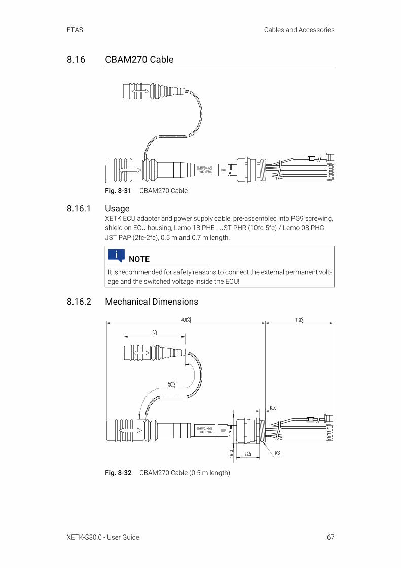
ETAS Cables and Accessories
XETK-S30.0 - User Guide 67
8.16 CBAM270 Cable
Fig. 8-31 CBAM270 Cable
8.16.1 UsageXETK ECU adapter and power supply cable, pre-assembled into PG9 screwing, shield on ECU housing, Lemo 1B PHE - JST PHR (10fc-5fc) / Lemo 0B PHG - JST PAP (2fc-2fc), 0.5 m and 0.7 m length.
8.16.2 Mechanical Dimensions
Fig. 8-32 CBAM270 Cable (0.5 m length)
NOTEIt is recommended for safety reasons to connect the external permanent volt-age and the switched voltage inside the ECU!

ETAS Cables and Accessories
XETK-S30.0 - User Guide 68
Fig. 8-33 CBAM270 Cable (0.7 m length)
8.16.3 Mounting
8.16.4 Wiring
Fig. 8-34 Wiring: Permanent Power Supply inside ECU not available
NOTEFor using the cable with an ETK with solder pad, cut the plug and solder the wire direct to the solder pad.
NOTEFor mounting the cable, cut a PG9 thread into the ECU housing. For thin walled housings use a nut SM-PE 9. Available from Lapp, Order number: 52103210.
ECU
Ignition Key
12V
ECU GND
Permanent Supply 12V
ECUConnector
Cable K70
ETK
Pad for Power Supplyor additional
Power Connector
Power Supply Connector
Vehicle
Battery
VehicleWiring
Serial ETK InterfaceConnector
Cable CBAM270.0
E.g. Cable CBE200
Cable Gland
Cable CBAM270.0

ETAS Cables and Accessories
XETK-S30.0 - User Guide 69
8.16.5 Temperature Range
8.16.6 Ordering Information
Condition Temperature RangeOperating temperature -40 °C to +125 °C
Order Name Short Name Order NumberXETK ECU Adapter and Power Supply Cable, pre-assembled into PG9 screwing, shield on ECU-Housing, Lemo 1B PHE - JST PHR (10fc-5fc) / Lemo 0B PHG - JST PAP (2fc-2fc), 0m50
CBAM270.0-0m5 F 00K 107 866
XETK ECU Adapter and Power Supply Cable, pre-assembled into PG9 screwing, shield on ECU-Housing, Lemo 1B PHE - JST PHR (10fc-5fc) / Lemo 0B PHG - JST PAP (2fc-2fc), 0m70
CBAM270.0-0m7 F 00K 108 479

ETAS Cables and Accessories
XETK-S30.0 - User Guide 70
8.17 K70.1 Cable
Fig. 8-35 K70.1 Cable
8.17.1 UsageExternal power supply cable for ETKs. It is used for ETKs without permanent power supply inside the ECU. Counterpart is the KA50 or several ETK Ethernet pig tails with external power supply, mounted inside the ECU.
8.17.2 Mechanical Dimensions
Fig. 8-36 K70.1 Cable Dimensions
8.17.3 Wiring
8.17.3.1 Wiring using K70.1 with KA50 Cable
Fig. 8-37 Wiring using K70.1 Cable with KA50 Cable
NOTEIt is recommended for safety reasons to connect the external permanent volt-age and the switched voltage inside the ECU !
Dimension Millimeters InchesA 2000 78.74
ECU
Ignition Key
12V
ECU GND
ECUConnector
ETK
Pad , Cable or Connector for Power
Supply
Power Supply Connector
Vehicle
Battery
VehicleWiring
Cable ETV 2
Serial ETK InterfaceConnector
(X) ETK Ethernet Cable
Cable Gland
Permanent Supply 12V
Cable K 70.1 KA 50

ETAS Cables and Accessories
XETK-S30.0 - User Guide 71
8.17.3.2 Wiring using ETK Pig Tail
Fig. 8-38 Wiring using K70.1 Cable with ETK Pig Tail (external Power Supply)
8.17.4 Temperature Range
8.17.5 Ordering Information
Condition Temperature RangeOperating temperature -40 °C to +120 °C,
litz wire up to 150 °C
Order Name Short Name Order NumberExternal Power Supply Cable for ETKs, Lemo 0B FGG - open wire (2mc-1c), 2m
K70.1 F 00K 109 270
ECU
Ignition Key
12V
ECU GND
Permanent Supply 12V
ECUConnector
Cable K 70.1
ETK
Pad , Cable or Connector for Power
Supply
Power Supply Connector
Vehicle
Battery
VehicleWiring
Cable ETV 2
Serial ETK InterfaceConnector
(X) ETK Ethernetpig tail
(X ) ETK Ethernet Cable
Cable Gland(X) ETK Ethernet
pig tail

ETAS Cables and Accessories
XETK-S30.0 - User Guide 72
8.18 KA50 Cable
Fig. 8-39 KA50 Power Supply Cable
8.18.1 UsageExternal power supply cable for ETKs. It is used for ETKs without permanent power supply inside the ECU. Counterpart is the K70 cable. Using the cable with an ETK with solder pad for the additional UBat input, cut the power connector and solder the wire direct to the solder pad.
8.18.2 Mechanical Dimensions
Fig. 8-40 KA50 Cable Dimensions
8.18.3 Wiring
Fig. 8-41 Wiring using K50 Cable with K70.1 Cable
NOTEFor safety reasons it is recommended to connect the external permanent voltage and the switched voltage inside the ECU.
Dimension Millimeters InchesA 200 7.87B 50 1.97
A
B
ECU
Ignition Key
12V
ECU GND
ECUConnector
ETK
Pad for Power Supplyor additional Power
Connector
Power Supply Connector
Vehicle
Battery
VehicleWiring
Cable ETV2
Serial ETK InterfaceConnector
Cable CBM150
Cable Gland
PermanentSupply 12V
Cable K70 KA50

ETAS Cables and Accessories
XETK-S30.0 - User Guide 73
8.18.4 Ordering Information
Order Name Short Name Order NumberXETK Power Supply Cable for External Supply, with Filter Coil, Lemo 0B EGG - open wire (2fc-1c), 0m2
KA50 F 00K 000 940

ETAS Ordering Information
XETK-S30.0 - User Guide 74
9 Ordering Information
9.1 XETK-S30.0
9.2 Cables and Adapter
Please contact your local ETAS representative for further cable information.
9.3 XETK - ECU Adapter
Order Name Short Name Order NumberXETK-S30.0C Emulator Probe for the Infineon AURIX MCU family
XETK-S30.0C F 00K 109 303
Package Contents• XETK-S30.0C Emulator Probe for the
Infineon AURIX MCU family,• List "Content of this Package",• ETK Safety Advice, including China
RoHS leaflet
NOTEWe recommend to use ETAS cables or any other cables certified by the stan-dards for the application. Adhere to the maximum permissible cable lengths!
NOTEApplication-specific cables are available from ETAS. Please contact your ETAS contact partner or e-mail [email protected].
Order Name Short Name Order NumberETAM2 XETK/FETK ECU Adapter, MOLEX - open wires (6fc - 6c), 0m25
ETAM2 F 00K 109 306
ETAM3 XETK/FETK ECU Adapter, SAM-TEC FFSD - SAMTEC SFM (10fc - 10fc), 0m11
ETAM3 F 00K 109 673
ETAM5 FETK ECU Adapter, MOLEX - MOLEX (6fc - 5fc+1c), 0m136
ETAM5 F 00K 110 101
ETAM9 F/XETK-S ECU Adapter, MOLEX - MOLEX (6fc - 5fc), 0m136
ETAM9 F 00K-111-043
ETAM10 F/XETK-S ECU Adapter, MOLEX - MOLEX (6fc - 6fc), 0m07
ETAM10 F 00K-111-814
MOLEX - MOLEX (6fc - 6fc) adapter cable ETAM12 (0,1 m / 0,33 ft) for connecting an F/XETK to the ECU
ETAM12 F 00K-112-457
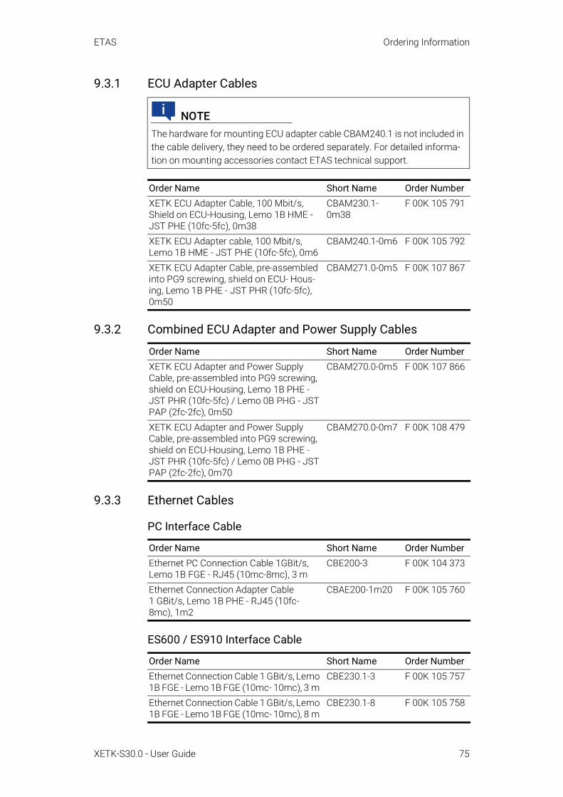
ETAS Ordering Information
XETK-S30.0 - User Guide 75
9.3.1 ECU Adapter Cables
9.3.2 Combined ECU Adapter and Power Supply Cables
9.3.3 Ethernet Cables
PC Interface Cable
ES600 / ES910 Interface Cable
NOTEThe hardware for mounting ECU adapter cable CBAM240.1 is not included in the cable delivery, they need to be ordered separately. For detailed informa-tion on mounting accessories contact ETAS technical support.
Order Name Short Name Order NumberXETK ECU Adapter Cable, 100 Mbit/s, Shield on ECU-Housing, Lemo 1B HME - JST PHE (10fc-5fc), 0m38
CBAM230.1-0m38
F 00K 105 791
XETK ECU Adapter cable, 100 Mbit/s, Lemo 1B HME - JST PHE (10fc-5fc), 0m6
CBAM240.1-0m6 F 00K 105 792
XETK ECU Adapter Cable, pre-assembled into PG9 screwing, shield on ECU- Hous-ing, Lemo 1B PHE - JST PHR (10fc-5fc), 0m50
CBAM271.0-0m5 F 00K 107 867
Order Name Short Name Order NumberXETK ECU Adapter and Power Supply Cable, pre-assembled into PG9 screwing, shield on ECU-Housing, Lemo 1B PHE - JST PHR (10fc-5fc) / Lemo 0B PHG - JST PAP (2fc-2fc), 0m50
CBAM270.0-0m5 F 00K 107 866
XETK ECU Adapter and Power Supply Cable, pre-assembled into PG9 screwing, shield on ECU-Housing, Lemo 1B PHE - JST PHR (10fc-5fc) / Lemo 0B PHG - JST PAP (2fc-2fc), 0m70
CBAM270.0-0m7 F 00K 108 479
Order Name Short Name Order NumberEthernet PC Connection Cable 1GBit/s, Lemo 1B FGE - RJ45 (10mc-8mc), 3 m
CBE200-3 F 00K 104 373
Ethernet Connection Adapter Cable 1 GBit/s, Lemo 1B PHE - RJ45 (10fc- 8mc), 1m2
CBAE200-1m20 F 00K 105 760
Order Name Short Name Order NumberEthernet Connection Cable 1 GBit/s, Lemo 1B FGE - Lemo 1B FGE (10mc- 10mc), 3 m
CBE230.1-3 F 00K 105 757
Ethernet Connection Cable 1 GBit/s, Lemo 1B FGE - Lemo 1B FGE (10mc- 10mc), 8 m
CBE230.1-8 F 00K 105 758

ETAS Ordering Information
XETK-S30.0 - User Guide 76
ES600 Interface Adapter Cable
9.3.4 Power Supply Cables
9.4 Power Supply
Order Name Short Name Order NumberEthernet Connection Adapter Cable 1 GBit/s to 100 MBit/s, Lemo 1B PHE - Lemo 1B FGF (10fc-8mc), 0m5
CBAE330.2-0m5 F 00K 105 759
Order Name Short Name Order NumberExternal Power Supply Cable for ETKs, Lemo 0B FGG - open wire (2mc-1c), 2m
K70.1 F 00K 109 270
XETK Power Supply Cable for External Supply, with Filter Coil, Lemo 0B EGG - open wire (2fc-1c), 0m2
KA50 F 00K 000 940
Order Name Short Name Order NumberIsolated Power Supply Interface for XETK ETP2 F 00K 104 010

ETAS Contact Information
XETK-S30.0 - User Guide 77
10 Contact Information
ETAS HeadquartersETAS GmbH
ETAS Subsidiaries and Technical SupportFor details of your local sales office as well as your local technical support team and product hotlines, take a look at the ETAS website:
Borsigstraße 24 Phone: +49 711 3423-070469 Stuttgart Fax: +49 711 3423-2106Germany Internet: www.etas.com
ETAS subsidiaries Internet: www.etas.com/en/contact.phpETAS technical support Internet: www.etas.com/en/hotlines.php

ETAS Figures
XETK-S30.0 - User Guide 78
FiguresFig. 2-1 Adhesive Label (Example: Label for XETK-S14.0) . . . . . . . . . . . . . . . . . . . . . . . . .12
Fig. 2-2 WEEE-Symbol . . . . . . . . . . . . . . . . . . . . . . . . . . . . . . . . . . . . . . . . . . . . . . . . . . . . . . . .13
Fig. 3-1 XETK-S30.0 . . . . . . . . . . . . . . . . . . . . . . . . . . . . . . . . . . . . . . . . . . . . . . . . . . . . . . . . . .15
Fig. 4-1 XETK-S30.0 Architecture . . . . . . . . . . . . . . . . . . . . . . . . . . . . . . . . . . . . . . . . . . . . . .17
Fig. 4-2 Location of the ECU Interfaces CON2 and CON4 . . . . . . . . . . . . . . . . . . . . . . . . . .19
Fig. 4-3 ETAM3 Adapter mounted at the ECU Interface CON2 . . . . . . . . . . . . . . . . . . . . .19
Fig. 4-4 Location of the XETK Ethernet Interface connector (CON1) . . . . . . . . . . . . . . . .20
Fig. 4-5 Location of the XETK-S30.0 Power Supply Connectors . . . . . . . . . . . . . . . . . . . .21
Fig. 4-6 Equivalent Circuitry of the ECU DAP Interface (ECU) . . . . . . . . . . . . . . . . . . . . . . .25
Fig. 5-1 XETK-S30.0 Connection to the ECU . . . . . . . . . . . . . . . . . . . . . . . . . . . . . . . . . . . . .28
Fig. 5-2 XETK-S30.0 Connection to the ECU . . . . . . . . . . . . . . . . . . . . . . . . . . . . . . . . . . . . .29
Fig. 5-3 Wiring - XETK Ethernet Interface . . . . . . . . . . . . . . . . . . . . . . . . . . . . . . . . . . . . . . . .30
Fig. 5-4 Permanent Power Supply inside ECU available . . . . . . . . . . . . . . . . . . . . . . . . . . .31
Fig. 5-5 Permanent Power Supply inside ECU not available . . . . . . . . . . . . . . . . . . . . . . . .31
Fig. 5-6 Isolated Power Supply inside ECU . . . . . . . . . . . . . . . . . . . . . . . . . . . . . . . . . . . . . .31
Fig. 7-1 XETK-S30.0 Interface Location . . . . . . . . . . . . . . . . . . . . . . . . . . . . . . . . . . . . . . . . .42
Fig. 7-2 XETK Ethernet Interface Connector CON1 Location . . . . . . . . . . . . . . . . . . . . . . .42
Fig. 7-3 ECU Interface Connector CON2 Location . . . . . . . . . . . . . . . . . . . . . . . . . . . . . . . .43
Fig. 7-4 VDDSTBY_SENSE Connector CON3 Location . . . . . . . . . . . . . . . . . . . . . . . . . . . .43
Fig. 7-5 Power Supply Connector CON4 Location . . . . . . . . . . . . . . . . . . . . . . . . . . . . . . . .44
Fig. 7-6 XETK-S30.0 Dimensions - Top View (1) . . . . . . . . . . . . . . . . . . . . . . . . . . . . . . . . . .45
Fig. 7-7 XETK-S30.0 Dimensions - Top View (2) . . . . . . . . . . . . . . . . . . . . . . . . . . . . . . . . . .46
Fig. 7-8 XETK-S30.0 Dimensions - Side View . . . . . . . . . . . . . . . . . . . . . . . . . . . . . . . . . . . .46
Fig. 8-1 CBAM230 Cable . . . . . . . . . . . . . . . . . . . . . . . . . . . . . . . . . . . . . . . . . . . . . . . . . . . . . .48
Fig. 8-2 CBAM230 Cable Dimensions . . . . . . . . . . . . . . . . . . . . . . . . . . . . . . . . . . . . . . . . . . .48
Fig. 8-3 Dimension Panel Cut-Out . . . . . . . . . . . . . . . . . . . . . . . . . . . . . . . . . . . . . . . . . . . . . .48
Fig. 8-4 Lemo Spanner . . . . . . . . . . . . . . . . . . . . . . . . . . . . . . . . . . . . . . . . . . . . . . . . . . . . . . . .48
Fig. 8-5 CBAM240 Cable . . . . . . . . . . . . . . . . . . . . . . . . . . . . . . . . . . . . . . . . . . . . . . . . . . . . . .50
Fig. 8-6 CBAM240 Cable Dimensions . . . . . . . . . . . . . . . . . . . . . . . . . . . . . . . . . . . . . . . . . . .50
Fig. 8-7 Long Thread . . . . . . . . . . . . . . . . . . . . . . . . . . . . . . . . . . . . . . . . . . . . . . . . . . . . . . . . .50
Fig. 8-8 Short Thread . . . . . . . . . . . . . . . . . . . . . . . . . . . . . . . . . . . . . . . . . . . . . . . . . . . . . . . .51
Fig. 8-9 CBAM271 Cable . . . . . . . . . . . . . . . . . . . . . . . . . . . . . . . . . . . . . . . . . . . . . . . . . . . . . .52
Fig. 8-10 CBAM271 Cable Dimensions . . . . . . . . . . . . . . . . . . . . . . . . . . . . . . . . . . . . . . . . . . .52
Fig. 8-11 FETK/ XETK - ECU Adapter ETAM2 . . . . . . . . . . . . . . . . . . . . . . . . . . . . . . . . . . . . .53
Fig. 8-12 ETAM2 Connector . . . . . . . . . . . . . . . . . . . . . . . . . . . . . . . . . . . . . . . . . . . . . . . . . . . .53
Fig. 8-13 ETAM3 ECU Adapter . . . . . . . . . . . . . . . . . . . . . . . . . . . . . . . . . . . . . . . . . . . . . . . . . .54

ETAS Figures
XETK-S30.0 - User Guide 79
Fig. 8-14 ETAM3 Adapter (top view) . . . . . . . . . . . . . . . . . . . . . . . . . . . . . . . . . . . . . . . . . . . . .54
Fig. 8-15 ETAM3 Adapter (side view) . . . . . . . . . . . . . . . . . . . . . . . . . . . . . . . . . . . . . . . . . . . .54
Fig. 8-16 ETAM3 Adapter (pin numbering) . . . . . . . . . . . . . . . . . . . . . . . . . . . . . . . . . . . . . . . .54
Fig. 8-17 FETK/ XETK - ECU Adapter ETAM5 . . . . . . . . . . . . . . . . . . . . . . . . . . . . . . . . . . . . .56
Fig. 8-18 FETK/ XETK - ECU Adapter ETAM5 . . . . . . . . . . . . . . . . . . . . . . . . . . . . . . . . . . . . .56
Fig. 8-19 FETK/ XETK - ECU Adapter ETAM9 . . . . . . . . . . . . . . . . . . . . . . . . . . . . . . . . . . . . .58
Fig. 8-20 FETK/ XETK - ECU Adapter ETAM10 . . . . . . . . . . . . . . . . . . . . . . . . . . . . . . . . . . . .59
Fig. 8-21 ETAM10 Adapter Dimensions . . . . . . . . . . . . . . . . . . . . . . . . . . . . . . . . . . . . . . . . . .59
Fig. 8-22 FETK / XETK - ECU Adapter ETAM12 . . . . . . . . . . . . . . . . . . . . . . . . . . . . . . . . . . . .61
Fig. 8-23 ETAM12 Adapter Dimensions . . . . . . . . . . . . . . . . . . . . . . . . . . . . . . . . . . . . . . . . . .61
Fig. 8-24 CBE200 Cable . . . . . . . . . . . . . . . . . . . . . . . . . . . . . . . . . . . . . . . . . . . . . . . . . . . . . . . .63
Fig. 8-25 CBAE200 Cable . . . . . . . . . . . . . . . . . . . . . . . . . . . . . . . . . . . . . . . . . . . . . . . . . . . . . . .64
Fig. 8-26 CBAE200 Cable Dimensions . . . . . . . . . . . . . . . . . . . . . . . . . . . . . . . . . . . . . . . . . . .64
Fig. 8-27 CBE230 Cable . . . . . . . . . . . . . . . . . . . . . . . . . . . . . . . . . . . . . . . . . . . . . . . . . . . . . . . .65
Fig. 8-28 CBE230 Cable Dimensions . . . . . . . . . . . . . . . . . . . . . . . . . . . . . . . . . . . . . . . . . . . . .65
Fig. 8-29 CBAE330 Cable . . . . . . . . . . . . . . . . . . . . . . . . . . . . . . . . . . . . . . . . . . . . . . . . . . . . . . .66
Fig. 8-30 CBAE330 Cable Dimensions . . . . . . . . . . . . . . . . . . . . . . . . . . . . . . . . . . . . . . . . . . .66
Fig. 8-31 CBAM270 Cable . . . . . . . . . . . . . . . . . . . . . . . . . . . . . . . . . . . . . . . . . . . . . . . . . . . . . .67
Fig. 8-32 CBAM270 Cable (0.5 m length) . . . . . . . . . . . . . . . . . . . . . . . . . . . . . . . . . . . . . . . . .67
Fig. 8-33 CBAM270 Cable (0.7 m length) . . . . . . . . . . . . . . . . . . . . . . . . . . . . . . . . . . . . . . . . .68
Fig. 8-34 Wiring: Permanent Power Supply inside ECU not available . . . . . . . . . . . . . . . . .68
Fig. 8-35 K70.1 Cable . . . . . . . . . . . . . . . . . . . . . . . . . . . . . . . . . . . . . . . . . . . . . . . . . . . . . . . . . .70
Fig. 8-36 K70.1 Cable Dimensions . . . . . . . . . . . . . . . . . . . . . . . . . . . . . . . . . . . . . . . . . . . . . . .70
Fig. 8-37 Wiring using K70.1 Cable with KA50 Cable . . . . . . . . . . . . . . . . . . . . . . . . . . . . . . .70
Fig. 8-38 Wiring using K70.1 Cable with ETK Pig Tail (external Power Supply) . . . . . . . .71
Fig. 8-39 KA50 Power Supply Cable . . . . . . . . . . . . . . . . . . . . . . . . . . . . . . . . . . . . . . . . . . . . .72
Fig. 8-40 KA50 Cable Dimensions . . . . . . . . . . . . . . . . . . . . . . . . . . . . . . . . . . . . . . . . . . . . . . .72
Fig. 8-41 Wiring using K50 Cable with K70.1 Cable . . . . . . . . . . . . . . . . . . . . . . . . . . . . . . . .72

XETK-S30.0 - User Guide 80
ETAS Index
Index
AAccident prevention . . . . . . . . . . . . . . . . . .9Adapter
ETAM10 . . . . . . . . . . . . . . . . . . . . . . . .59ETAM12 . . . . . . . . . . . . . . . . . . . . . . . .61ETAM2 . . . . . . . . . . . . . . . . . . . . . 53, 56ETAM3 . . . . . . . . . . . . . . . . . . . . . . . . .54ETAM5 . . . . . . . . . . . . . . . . . . . . . . . . .56ETAM9 . . . . . . . . . . . . . . . . . . . . . . . . .58
Applications . . . . . . . . . . . . . . . . . . . . . . . .15Architecture . . . . . . . . . . . . . . . . . . . . . . . .17BBlockdiagram . . . . . . . . . . . . . . . . . . . . . . .17CCable
CBAE330 . . . . . . . . . . . . . . . . . . . . . . .66CBAM230 . . . . . . . . . . . . . . . . . . . . . .48CBAM240 . . . . . . . . . . . . . . . . . . . . . .50CBAM270 . . . . . . . . . . . . . . . . . . . . . .67CBAM271 . . . . . . . . . . . . . . . . . . . . . .52CBE200-x . . . . . . . . . . . . . . . . . . . . . . .63CBE230 . . . . . . . . . . . . . . . . . . . . . . . .65Overview and Classification . . . . . . .47Power Supply . . . . . . . . . . . . . . . 75, 76
Configuration . . . . . . . . . . . . . . . . . . . . . . .36Parameter . . . . . . . . . . . . . . . . . . . . . .33
ConnectorPower Supply . . . . . . . . . . . . . . . . . . .21XETK Ethernet Interface . . . . . . . . . .20
DDAP Interface . . . . . . . . . . . . . . . . . . . . . . .25Data
Emulation . . . . . . . . . . . . . . . . . . . . . .23Emulation Memory . . . . . . . . . . . . . .36Measurement . . . . . . . . . . . . . . . . . . .23Measurement Memory . . . . . . . . . . .36
Documentation . . . . . . . . . . . . . . . . . . . . . .9EECU Interface . . . . . . . . . . . . . . . . . . . . . . .19ECU Voltage Supervisor . . . . . . . . . . . . . .22Electrical Characteristics . . . . . . . . . . . . .41Emulation Data . . . . . . . . . . . . . . . . . . . . .23Environmental Conditions . . . . . . . . . . . .37Ethernet Interface . . . . . . . . . . . . . . . . . . .20ETK Configuration . . . . . . . . . . . . . . . . . . .32FFeatures . . . . . . . . . . . . . . . . . . . . . . . . . . .16HHardware Description . . . . . . . . . . . . . . . .17IIdentifications on the Product . . . . . . . . .12
InterfaceECU . . . . . . . . . . . . . . . . . . . . . . . . . . . .19
Introduction . . . . . . . . . . . . . . . . . . . . . . . .15Isolated Power Supply . . . . . . . . . . . . . . .31LLED . . . . . . . . . . . . . . . . . . . . . . . . . . . . . . . .23MMeasurement
Data . . . . . . . . . . . . . . . . . . . . . . . . . . .23Data Memory . . . . . . . . . . . . . . . . . . .36
Mechanical Dimension . . . . . . . . . . . . . . .45OOrdering Information . . . . . . . . . . . . . . . .74PParameter
Configuration . . . . . . . . . . . . . . . . . . .33PC Network Adapter . . . . . . . . . . . . . . . . .34Pin Assignment . . . . . . . . . . . . . . . . . . . . .42Power Supply . . . . . . . . . . . . 21, 22, 31, 76
Cable . . . . . . . . . . . . . . . . . . . . . . 75, 76Connector . . . . . . . . . . . . . . . . . . . . . .21
ProductExclusion of Liability . . . . . . . . . . . . . . 9
Product Back . . . . . . . . . . . . . . . . . . . . . . .13QQualification, required . . . . . . . . . . . . . . . . 9RREACH Regulation (EU) . . . . . . . . . . . . . .14Recycling . . . . . . . . . . . . . . . . . . . . . . . . . .13Reset . . . . . . . . . . . . . . . . . . . . . . . . . . . . . .27RoHS conformity
China . . . . . . . . . . . . . . . . . . . . . . . . . .14European Union . . . . . . . . . . . . . . . . .14
SSafety at Work . . . . . . . . . . . . . . . . . . . . . . . 9Safety precautions . . . . . . . . . . . . . . . . . . . 9Software Support . . . . . . . . . . . . . . . . . . .35Status LED . . . . . . . . . . . . . . . . . . . . . . . . .23System Requirements . . . . . . . . . . . . . . .34TTest Characteristics . . . . . . . . . . . . . . . . .39UUKCA conformity . . . . . . . . . . . . . . . . . . .14Use, intended . . . . . . . . . . . . . . . . . . . . . . . . 9VVoltage Supervisor . . . . . . . . . . . . . . . . . .22WWaste Electrical and Electronic Equipment
. . . . . . . . . . . . . . . . . . . . . . . . . . . .13

XETK-S30.0 - User Guide 81
ETAS Index
WEEE . . . . . . . . . . . . . . . . . . . . . . . . . . . . . .13WEEE take-back system . . . . . . . . . . . . .13XXETK Ethernet Interface . . . . . . . . . . . . . .20


