88
| Date post: | 22-Oct-2015 |
| Category: |
Documents |
| Upload: | amirbahram |
| View: | 280 times |
| Download: | 7 times |


���� ��� �� ������ � �� � ���
ETERNUS DX80 S2/DX90 S2 Disk storage system OverviewCopyright 2012 FUJITSU LIMITED P3AM-4812-06ENZ0
3
Preface
Fujitsu would like to thank you for purchasing our ETERNUS DX80 S2/DX90 S2 Disk storage system.The ETERNUS DX80 S2/DX90 S2 Disk storage system is designed to be connected to Fujitsu(PRIMEQUEST or PRIMERGY) or non-Fujitsu servers.This manual describes the basic knowledge that is required to use the ETERNUS DX80 S2/DX90 S2Disk storage system.This manual is intended for use of ETERNUS DX80 S2/DX90 S2 Disk storage system in regions otherthan Japan.Please carefully review the information outlined in this manual.
Sixth EditionAugust 2012
All SPARC trademarks are used under license and are trademarks or registered trademarks of SPARCInternational, Inc. in the United States and other countries.UNIX is a registered trademark of The Open Group in the United States and other countries.Microsoft, Windows, and Windows Server are either registered trademarks or trademarks of MicrosoftCorporation in the United States and/or other countries.Oracle and Java are registered trademarks of Oracle and/or its affiliates.HP-UX is a trademark of Hewlett-Packard Company in the U.S. and other countries.Linux is a trademark or registered trademark of Linus Torvalds in the U.S. and other countries.Red Hat, PRM, and all Red Hat-based trademarks and logos are trademarks or registered trademarksof Red Hat, Inc. in the USA and other countries.SUSE is a registered trademark of SUSE Linux AG., a subsidiary of Novell, Inc.AIX is a trademark of IBM Corp.VMware, VMware logos, Virtual SMP, and VMotion are either registered trademarks or trademarks ofVMware, Inc. in the U.S. and/or other countries.The company names, product names and service names mentioned in this document are registeredtrademarks or trademarks of their respective companies.
About this Manual
Organization
This manual is composed of the following six chapters:
● Chapter 1 Overview
This chapter provides an overview and describes the features of the ETERNUS DX80 S2/DX90 S2Disk storage system.
● Chapter 2 Specifications
This chapter describes the specifications, the function specifications, and the operating environmentof the ETERNUS DX80 S2/DX90 S2 Disk storage system.
● Chapter 3 Connection Configurations
This chapter describes the different types of interfaces that can be used for connecting theETERNUS DX80 S2/DX90 S2 Disk storage system.
● Chapter 4 System Configuration
This chapter describes the basic knowledge required for RAID, the types and capacity of drives thatcan be used, and hot spares.
● Chapter 5 Basic Functions
This chapter provides an overview of the basic functions that are installed in the ETERNUS DX80S2/DX90 S2 Disk storage system.
● Chapter 6 Optional Functions
This chapter provides an overview of the optional functions that require license registration.
ETERNUS DX80 S2/DX90 S2 Disk storage system OverviewCopyright 2012 FUJITSU LIMITED P3AM-4812-06ENZ0
4
About this Manual
Naming Conventions
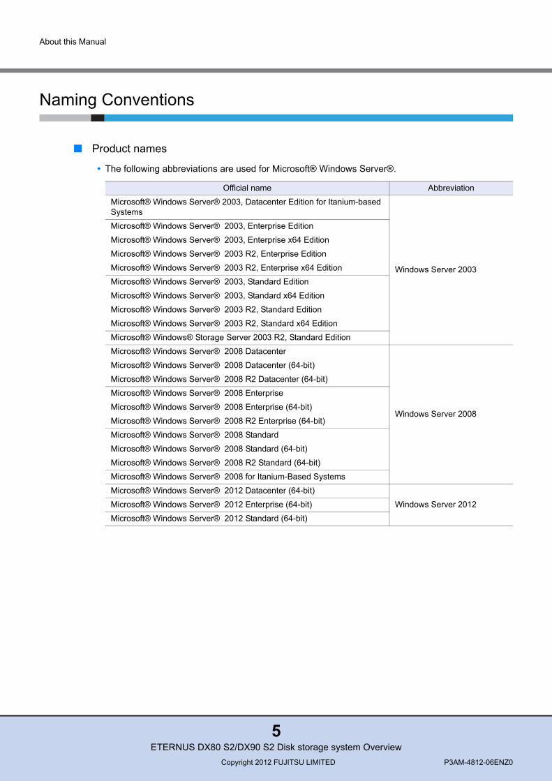
■ Product names
• The following abbreviations are used for Microsoft® Windows Server®.
Official name Abbreviation
Microsoft® Windows Server® 2003, Datacenter Edition for Itanium-based Systems
Windows Server 2003
Microsoft® Windows Server® 2003, Enterprise Edition
Microsoft® Windows Server® 2003, Enterprise x64 Edition
Microsoft® Windows Server® 2003 R2, Enterprise Edition
Microsoft® Windows Server® 2003 R2, Enterprise x64 Edition
Microsoft® Windows Server® 2003, Standard Edition
Microsoft® Windows Server® 2003, Standard x64 Edition
Microsoft® Windows Server® 2003 R2, Standard Edition
Microsoft® Windows Server® 2003 R2, Standard x64 Edition
Microsoft® Windows® Storage Server 2003 R2, Standard Edition
Microsoft® Windows Server® 2008 Datacenter
Windows Server 2008
Microsoft® Windows Server® 2008 Datacenter (64-bit)
Microsoft® Windows Server® 2008 R2 Datacenter (64-bit)
Microsoft® Windows Server® 2008 Enterprise
Microsoft® Windows Server® 2008 Enterprise (64-bit)
Microsoft® Windows Server® 2008 R2 Enterprise (64-bit)
Microsoft® Windows Server® 2008 Standard
Microsoft® Windows Server® 2008 Standard (64-bit)
Microsoft® Windows Server® 2008 R2 Standard (64-bit)
Microsoft® Windows Server® 2008 for Itanium-Based Systems
Microsoft® Windows Server® 2012 Datacenter (64-bit)
Windows Server 2012Microsoft® Windows Server® 2012 Enterprise (64-bit)
Microsoft® Windows Server® 2012 Standard (64-bit)
ETERNUS DX80 S2/DX90 S2 Disk storage system OverviewCopyright 2012 FUJITSU LIMITED P3AM-4812-06ENZ0
5
About this Manual
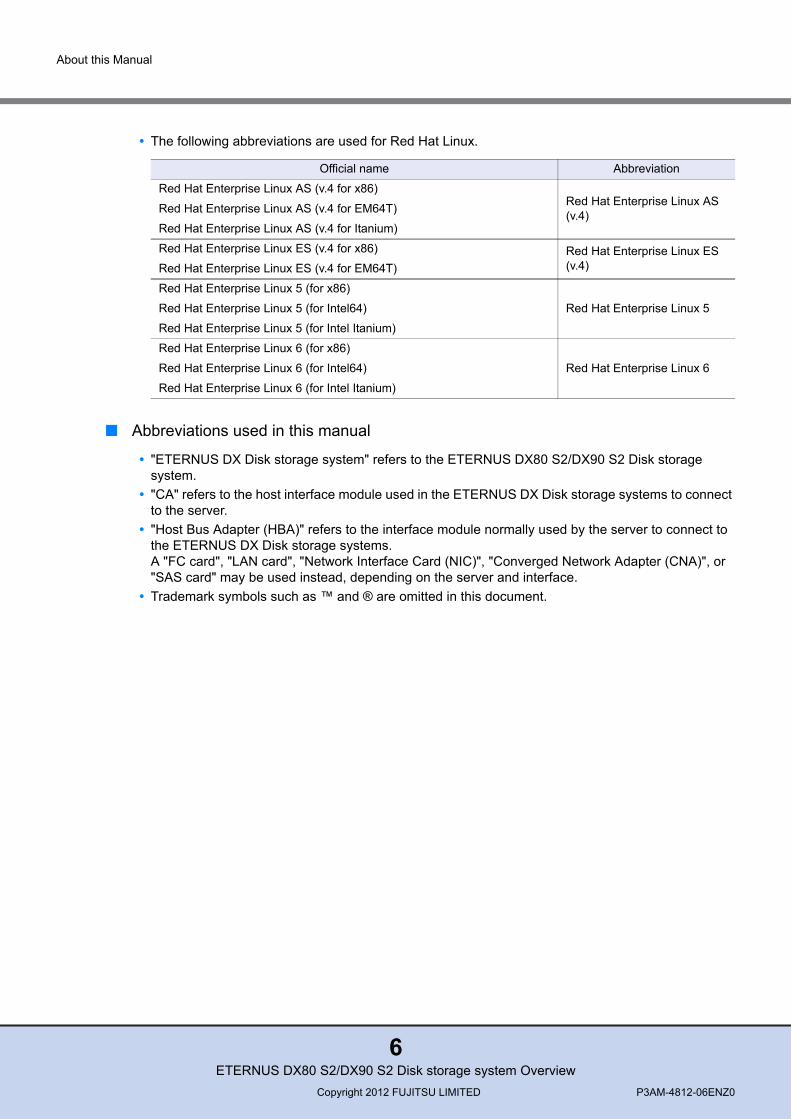
• The following abbreviations are used for Red Hat Linux.
■ Abbreviations used in this manual
• "ETERNUS DX Disk storage system" refers to the ETERNUS DX80 S2/DX90 S2 Disk storage system.
• "CA" refers to the host interface module used in the ETERNUS DX Disk storage systems to connect to the server.
• "Host Bus Adapter (HBA)" refers to the interface module normally used by the server to connect to the ETERNUS DX Disk storage systems. A "FC card", "LAN card", "Network Interface Card (NIC)", "Converged Network Adapter (CNA)", or "SAS card" may be used instead, depending on the server and interface.
• Trademark symbols such as ™ and ® are omitted in this document.
Official name Abbreviation
Red Hat Enterprise Linux AS (v.4 for x86)Red Hat Enterprise Linux AS (v.4)Red Hat Enterprise Linux AS (v.4 for EM64T)
Red Hat Enterprise Linux AS (v.4 for Itanium)
Red Hat Enterprise Linux ES (v.4 for x86) Red Hat Enterprise Linux ES (v.4)Red Hat Enterprise Linux ES (v.4 for EM64T)
Red Hat Enterprise Linux 5 (for x86)
Red Hat Enterprise Linux 5Red Hat Enterprise Linux 5 (for Intel64)
Red Hat Enterprise Linux 5 (for Intel Itanium)
Red Hat Enterprise Linux 6 (for x86)
Red Hat Enterprise Linux 6Red Hat Enterprise Linux 6 (for Intel64)
Red Hat Enterprise Linux 6 (for Intel Itanium)
ETERNUS DX80 S2/DX90 S2 Disk storage system OverviewCopyright 2012 FUJITSU LIMITED P3AM-4812-06ENZ0
6

Warning Notations
Warning signs are shown throughout this manual in order to prevent injury to the user and/or materialdamage. These signs are composed of a symbol and a message describing the recommended level ofcaution. The following explains the symbol, its level of caution, and its meaning as used in this manual
How Warnings are Presented in this Manual
A message is written beside the symbol indicating the caution level. This message is marked with avertical ribbon in the left margin, to distinguish this warning from ordinary descriptions.An example is shown here.
CAUTIONThis symbol indicates the possibility of minor or moderate personal injury, as well as damage to the ETERNUS DX Disk storage system and/or to other users and their property, if the ETERNUS DX Disk storage system is not used properly.
Warning Level Indicator
Warning Type Indicator
Warning Details
To avoid damaging the ETERNUS DX Disk storage system, pay attention to the following points when cleaning the ETERNUS DX Disk storage system:
- Make sure to disconnect the power when cleaning.- Be careful that no liquid seeps into the ETERNUS DX Disk storage
system when using cleaners, etc.- Do not use alcohol or other solvents to clean the ETERNUS DX Disk
storage system.
Warning Layout Ribbon
Example Warning
ETERNUS DX80 S2/DX90 S2 Disk storage system OverviewCopyright 2012 FUJITSU LIMITED P3AM-4812-06ENZ0
7

Table of Contents
Chapter 1 Overview 12
Chapter 2 Specifications 16
2.1 ETERNUS DX Disk Storage System Specifications ................................................. 162.1.1 ETERNUS DX80 S2 Specifications ..................................................................................................... 162.1.2 ETERNUS DX90 S2 Specifications ..................................................................................................... 17
2.2 Function Specifications ............................................................................................. 18
2.3 Supported OSes ....................................................................................................... 21
Chapter 3 Connection Configurations 27
3.1 Host Connections (SAN) ........................................................................................... 27
3.2 Remote Connections (SAN/WAN) ............................................................................ 28
3.3 LAN ........................................................................................................................... 29
3.4 Power Synchronization ............................................................................................. 29
Chapter 4 System Configuration 30
4.1 RAID Levels .............................................................................................................. 30
4.2 RAID Groups ............................................................................................................ 35
4.3 Volumes .................................................................................................................... 37
4.4 Drives ........................................................................................................................ 384.4.1 User Capacity of Drives ....................................................................................................................... 404.4.2 User Capacity for Each RAID Level ..................................................................................................... 414.4.3 Drive Installation .................................................................................................................................. 41
4.5 Hot Spares ................................................................................................................ 444.5.1 Hot Spare Types .................................................................................................................................. 444.5.2 Number of Hot Spares for Installation .................................................................................................. 44
Chapter 5 Basic Functions 46
5.1 Data Protection ......................................................................................................... 465.1.1 Data Block Guard ................................................................................................................................ 46
ETERNUS DX80 S2/DX90 S2 Disk storage system OverviewCopyright 2012 FUJITSU LIMITED P3AM-4812-06ENZ0
8

Table of Contents
5.1.2 Disk Patrol ........................................................................................................................................... 475.1.3 Redundant Copy .................................................................................................................................. 485.1.4 Rebuild/Copyback ................................................................................................................................ 49
5.2 Security ..................................................................................................................... 505.2.1 Account Management .......................................................................................................................... 505.2.2 User Authentication ............................................................................................................................. 515.2.3 Host Affinity .......................................................................................................................................... 535.2.4 Data Encryption ................................................................................................................................... 54
5.3 Volume Configuration Optimization .......................................................................... 565.3.1 RAID Migration .................................................................................................................................... 585.3.2 Logical Device Expansion .................................................................................................................... 605.3.3 LUN Concatenation ............................................................................................................................. 625.3.4 Wide Striping ....................................................................................................................................... 63
5.4 Burden Reduction on Environment ........................................................................... 645.4.1 Eco-mode ............................................................................................................................................ 645.4.2 Power Consumption Visualization ....................................................................................................... 65
5.5 Operation Monitoring ................................................................................................ 655.5.1 Operation Management Interface ........................................................................................................ 655.5.2 Event Notification ................................................................................................................................. 665.5.3 Performance Information Management ............................................................................................... 675.5.4 Assigned CMs ...................................................................................................................................... 685.5.5 Connection Operation Mode ................................................................................................................ 685.5.6 Device Time Synchronization .............................................................................................................. 705.5.7 Remote Power Operation (Wake On LAN) .......................................................................................... 71
5.6 Data Migration .......................................................................................................... 725.6.1 Storage Migration ................................................................................................................................ 72
Chapter 6 Optional Functions 73
6.1 Streamlined Operations in the Virtual Environment .................................................. 736.1.1 Thin Provisioning ................................................................................................................................. 736.1.2 Flexible Tier (Automatic Storage Layering) ......................................................................................... 74
6.2 Backup (Advanced Copy) ......................................................................................... 766.2.1 Local Copy ........................................................................................................................................... 786.2.2 Remote Copy ....................................................................................................................................... 806.2.3 Available Advanced Copy Combinations ............................................................................................. 83
ETERNUS DX80 S2/DX90 S2 Disk storage system OverviewCopyright 2012 FUJITSU LIMITED P3AM-4812-06ENZ0
9
ETERNUS DX80 S2/DX90 S2 Disk storage system OverviewCopyright 2012 FUJITSU LIMITED P3AM-4812-06ENZ0
10
List of Figures
Figure 1.1 External view ..................................................................................................................................... 12Figure 3.1 Connection configuration ................................................................................................................... 27Figure 4.1 RAID0 concept................................................................................................................................... 31Figure 4.2 RAID1 concept................................................................................................................................... 31Figure 4.3 RAID1+0 concept .............................................................................................................................. 32Figure 4.4 RAID5 concept................................................................................................................................... 32Figure 4.5 RAID5+0 concept .............................................................................................................................. 33Figure 4.6 RAID6 concept................................................................................................................................... 34Figure 4.7 Example of a RAID group .................................................................................................................. 35Figure 4.8 Volume concept ................................................................................................................................. 37Figure 4.9 Drive combination 1 ........................................................................................................................... 42Figure 4.10 Drive combination 2 ........................................................................................................................... 42Figure 4.11 Drive combination 3 ........................................................................................................................... 43Figure 4.12 Hot spares ......................................................................................................................................... 44Figure 5.1 Data block guard function .................................................................................................................. 46Figure 5.2 Disk check ......................................................................................................................................... 47Figure 5.3 Redundant Copy function .................................................................................................................. 48Figure 5.4 Rebuild/Copyback function ................................................................................................................ 49Figure 5.5 Account management........................................................................................................................ 50Figure 5.6 Host affinity ........................................................................................................................................ 53Figure 5.7 Data encryption.................................................................................................................................. 56Figure 5.8 Example of RAID Migration 1 ............................................................................................................ 58Figure 5.9 Example of RAID Migration 2 ............................................................................................................ 59Figure 5.10 Example of Logical Device Expansion 1............................................................................................ 60Figure 5.11 Example of Logical Device Expansion 2............................................................................................ 61Figure 5.12 Example of LUN Concatenation ........................................................................................................ 62Figure 5.13 Wide Striping ..................................................................................................................................... 63Figure 5.14 Eco-mode mechanism ....................................................................................................................... 64Figure 5.15 Power consumption visualization....................................................................................................... 65Figure 5.16 Event notification ............................................................................................................................... 67Figure 5.17 Assigned CM ..................................................................................................................................... 68Figure 5.18 Host response (connection operation mode)..................................................................................... 69Figure 5.19 Device time synchronization .............................................................................................................. 70Figure 5.20 Power control using Wake On LAN ................................................................................................... 71Figure 5.21 Storage Migration .............................................................................................................................. 72Figure 6.1 Example of Thin Provisioning ............................................................................................................ 74Figure 6.2 Flexible Tier (automatic storage layering).......................................................................................... 75Figure 6.3 Example of Advanced Copy .............................................................................................................. 76Figure 6.4 REC ................................................................................................................................................... 80Figure 6.5 Restore OPC ..................................................................................................................................... 83Figure 6.6 EC or REC Reverse........................................................................................................................... 83Figure 6.7 Multiple copy...................................................................................................................................... 84Figure 6.8 Multiple copy (including SnapOPC+)................................................................................................. 84Figure 6.9 Multiple copy (using the Consistency mode) ..................................................................................... 85Figure 6.10 Cascade copy .................................................................................................................................... 85Figure 6.11 Cascade copy (using three copy sessions) ....................................................................................... 86
ETERNUS DX80 S2/DX90 S2 Disk storage system OverviewCopyright 2012 FUJITSU LIMITED P3AM-4812-06ENZ0
11
List of Tables
Table 2.1 ETERNUS DX80 S2 specifications.................................................................................................... 16Table 2.2 ETERNUS DX90 S2 specifications.................................................................................................... 17Table 2.3 ETERNUS DX80 S2/DX90 S2 function specifications....................................................................... 18Table 2.4 Supported servers and OSes (FC interface) ..................................................................................... 21Table 2.5 Supported servers and OSes (iSCSI interface) ................................................................................. 24Table 2.6 Supported servers and OSes (FCoE interface) ................................................................................. 25Table 2.7 Supported servers and OSes (SAS interface) ................................................................................... 26Table 4.1 User capacity for each RAID level ..................................................................................................... 34Table 4.2 Recommended number of drives per RAID group............................................................................. 35Table 4.3 RAID configurations that can be registered in a Thin Provisioning Pool or a Flexible Tier Pool ....... 36Table 4.4 Volumes that can be created ............................................................................................................. 37Table 4.5 Drive characteristics .......................................................................................................................... 39Table 4.6 User capacity per drive ...................................................................................................................... 40Table 4.7 Formula for calculating user capacity for each RAID level ................................................................ 41Table 4.8 Recommended number of hot spares for each drive type................................................................. 44Table 4.9 Hot spare selection ............................................................................................................................ 45Table 5.1 Type of client public key .................................................................................................................... 51Table 5.2 Host affinity function specifications.................................................................................................... 54Table 5.3 Data encryption function specifications ............................................................................................. 55Table 6.1 Controlling software ........................................................................................................................... 77Table 6.2 List of functions (copy methods) ........................................................................................................ 77Table 6.3 REC data transfer mode .................................................................................................................... 80Table 6.4 Available cascade copy combinations ............................................................................................... 86
Chapter 1
OverviewThis chapter provides an overview and describes the features of the ETERNUS DX Disk storagesystem.
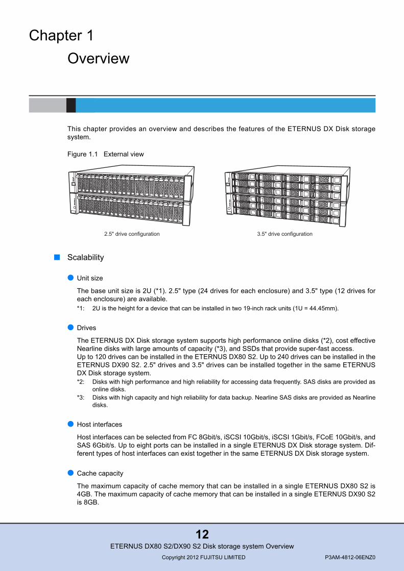
Figure 1.1 External view
■ Scalability
● Unit size
The base unit size is 2U (*1). 2.5" type (24 drives for each enclosure) and 3.5" type (12 drives foreach enclosure) are available. *1: 2U is the height for a device that can be installed in two 19-inch rack units (1U = 44.45mm).
● Drives
The ETERNUS DX Disk storage system supports high performance online disks (*2), cost effectiveNearline disks with large amounts of capacity (*3), and SSDs that provide super-fast access.Up to 120 drives can be installed in the ETERNUS DX80 S2. Up to 240 drives can be installed in theETERNUS DX90 S2. 2.5" drives and 3.5" drives can be installed together in the same ETERNUSDX Disk storage system. *2: Disks with high performance and high reliability for accessing data frequently. SAS disks are provided as
online disks.*3: Disks with high capacity and high reliability for data backup. Nearline SAS disks are provided as Nearline
disks.
● Host interfaces
Host interfaces can be selected from FC 8Gbit/s, iSCSI 10Gbit/s, iSCSI 1Gbit/s, FCoE 10Gbit/s, andSAS 6Gbit/s. Up to eight ports can be installed in a single ETERNUS DX Disk storage system. Dif-ferent types of host interfaces can exist together in the same ETERNUS DX Disk storage system.
● Cache capacity
The maximum capacity of cache memory that can be installed in a single ETERNUS DX80 S2 is4GB. The maximum capacity of cache memory that can be installed in a single ETERNUS DX90 S2is 8GB.
2.5" drive configuration 3.5" drive configuration
ETERNUS DX80 S2/DX90 S2 Disk storage system OverviewCopyright 2012 FUJITSU LIMITED P3AM-4812-06ENZ0
12
Chapter 1 Overview
● Model upgrade
As a support for system scalability after installation, an ETERNUS DX Disk storage system can beupgraded to a higher-end model. The ETERNUS DX80 S2 can be upgraded to the ETERNUS DX90S2. The ETERNUS DX80 S2/DX90 S2 can be upgraded to the ETERNUS DX410 S2/DX440 S2.
■ High reliability
● RAID levels
The ETERNUS DX Disk storage system supports RAID5+0 that is superior to RAID5 in reliabilityand performance, and RAID6 that responds to the double failure of disks, as well as RAID1,RAID1+0, and RAID5.
● Redundant configurations
Important components are duplicated to maintain high fault tolerance. This allows hot swapping offailed components without interrupting operations.
● Data protection against power failure
Since data is saved from the cache memory to the non-volatile memory in the controller when apower failure occurs, data can be retained indefinitely.
● Data integrity
The ETERNUS DX Disk storage system adds check codes to all data that is saved. The data isverified at multiple checkpoints on transmission paths to ensure data integrity.
● Monitoring for signs of failure
When a possible sign of drive failure is detected, the data of the suspect drive is restored to the hotspare and the suspect drive is switched while maintaining data redundancy.
● Data Encryption
The ETERNUS DX Disk storage system has the ability to encrypt data as it is being written. Encryp-tion with firmware is supported by default. Together with the world standard 128bit AES method (*4),Fujitsu's own high performance encryption method is also supported.In addition, Self Encrypting Drives (SEDs) are available. Since each drive performs self encryptioninstead of the firmware, loads that are usually caused by encryption using firmware are removedand data can be encrypted without reducing performance. SEDs use the 256bit AES method.*4: Advanced Encryption Standard: Federal Information Processing Standards method
ETERNUS DX80 S2/DX90 S2 Disk storage system OverviewCopyright 2012 FUJITSU LIMITED P3AM-4812-06ENZ0
13
Chapter 1 Overview
■ Operability
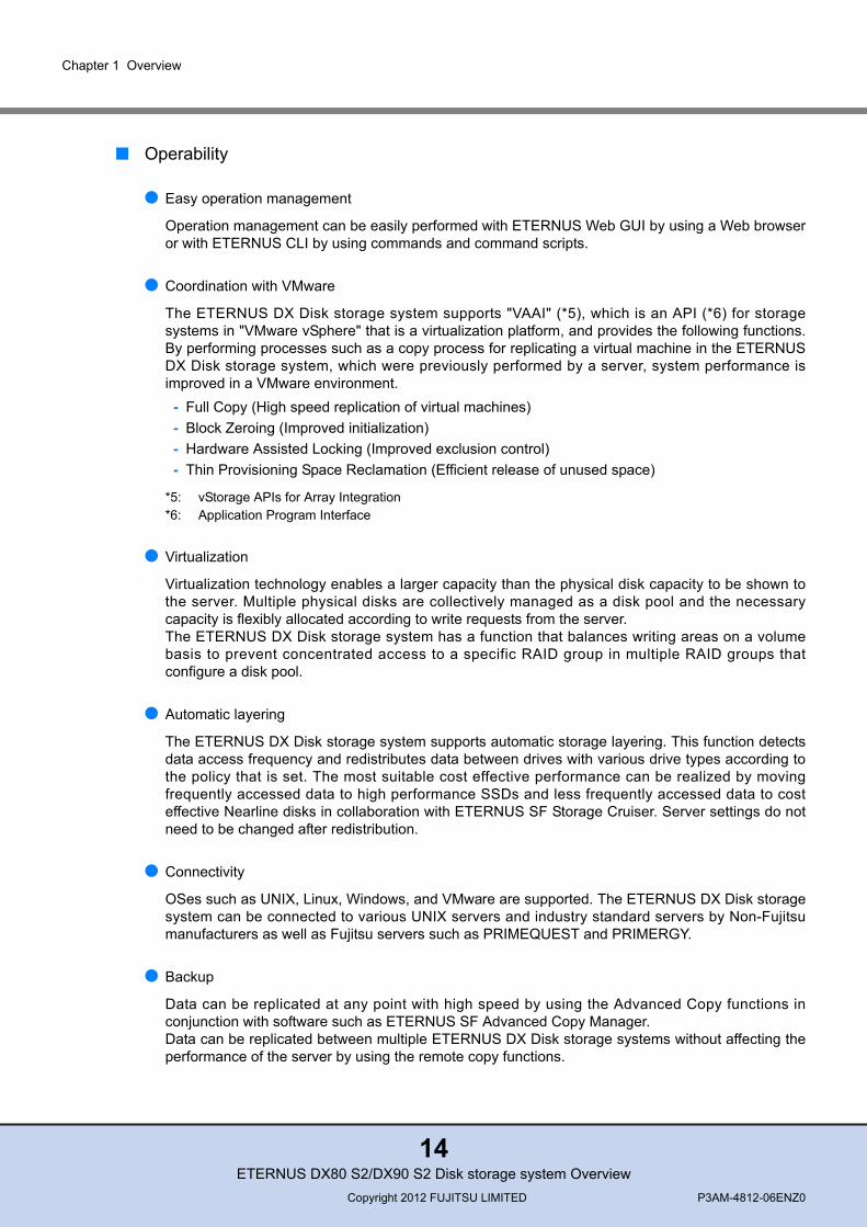
● Easy operation management
Operation management can be easily performed with ETERNUS Web GUI by using a Web browseror with ETERNUS CLI by using commands and command scripts.
● Coordination with VMware
The ETERNUS DX Disk storage system supports "VAAI" (*5), which is an API (*6) for storagesystems in "VMware vSphere" that is a virtualization platform, and provides the following functions.By performing processes such as a copy process for replicating a virtual machine in the ETERNUSDX Disk storage system, which were previously performed by a server, system performance isimproved in a VMware environment.
- Full Copy (High speed replication of virtual machines)- Block Zeroing (Improved initialization)- Hardware Assisted Locking (Improved exclusion control)- Thin Provisioning Space Reclamation (Efficient release of unused space)
*5: vStorage APIs for Array Integration*6: Application Program Interface
● Virtualization
Virtualization technology enables a larger capacity than the physical disk capacity to be shown tothe server. Multiple physical disks are collectively managed as a disk pool and the necessarycapacity is flexibly allocated according to write requests from the server.The ETERNUS DX Disk storage system has a function that balances writing areas on a volumebasis to prevent concentrated access to a specific RAID group in multiple RAID groups thatconfigure a disk pool.
● Automatic layering
The ETERNUS DX Disk storage system supports automatic storage layering. This function detectsdata access frequency and redistributes data between drives with various drive types according tothe policy that is set. The most suitable cost effective performance can be realized by movingfrequently accessed data to high performance SSDs and less frequently accessed data to costeffective Nearline disks in collaboration with ETERNUS SF Storage Cruiser. Server settings do notneed to be changed after redistribution.
● Connectivity
OSes such as UNIX, Linux, Windows, and VMware are supported. The ETERNUS DX Disk storagesystem can be connected to various UNIX servers and industry standard servers by Non-Fujitsumanufacturers as well as Fujitsu servers such as PRIMEQUEST and PRIMERGY.
● Backup
Data can be replicated at any point with high speed by using the Advanced Copy functions inconjunction with software such as ETERNUS SF Advanced Copy Manager.Data can be replicated between multiple ETERNUS DX Disk storage systems without affecting theperformance of the server by using the remote copy functions.
ETERNUS DX80 S2/DX90 S2 Disk storage system OverviewCopyright 2012 FUJITSU LIMITED P3AM-4812-06ENZ0
14
Chapter 1 Overview
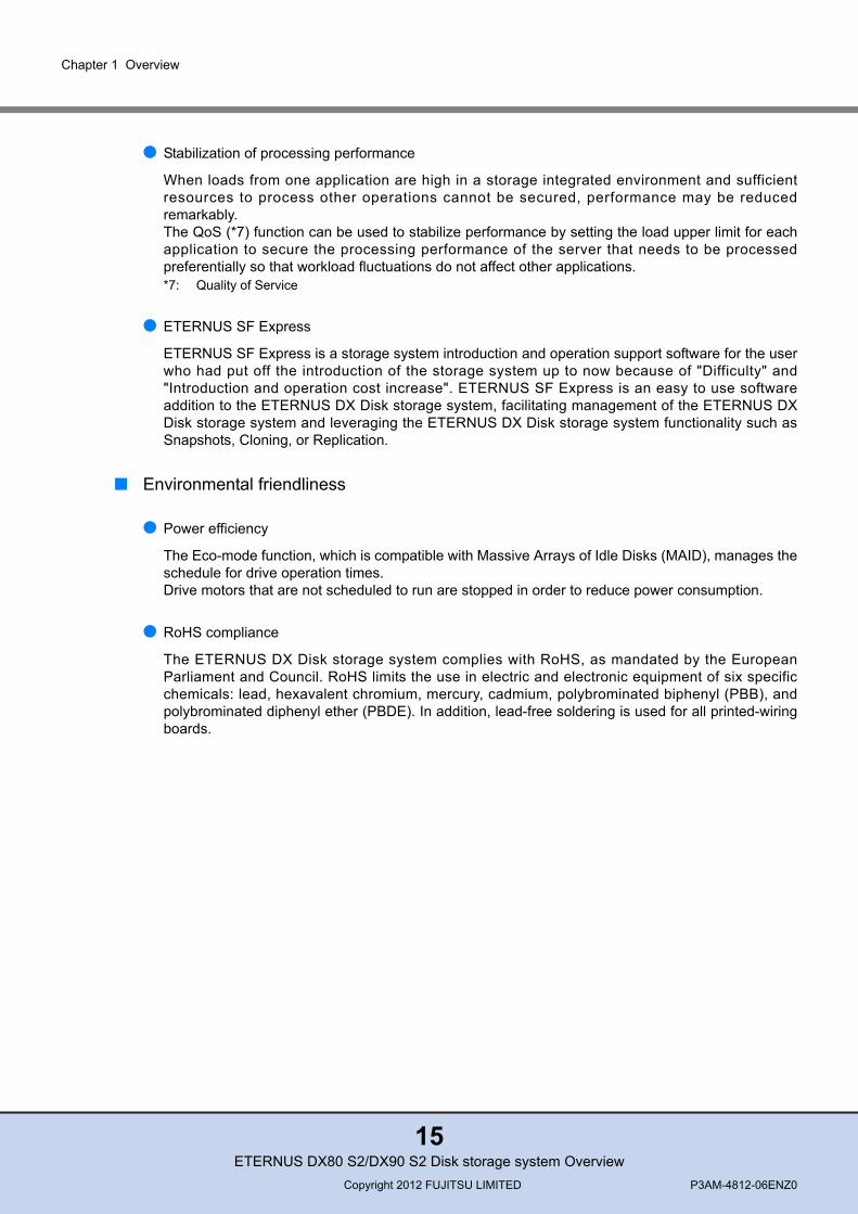
● Stabilization of processing performance
When loads from one application are high in a storage integrated environment and sufficientresources to process other operations cannot be secured, performance may be reducedremarkably.The QoS (*7) function can be used to stabilize performance by setting the load upper limit for eachapplication to secure the processing performance of the server that needs to be processedpreferentially so that workload fluctuations do not affect other applications. *7: Quality of Service
● ETERNUS SF Express
ETERNUS SF Express is a storage system introduction and operation support software for the userwho had put off the introduction of the storage system up to now because of "Difficulty" and"Introduction and operation cost increase". ETERNUS SF Express is an easy to use softwareaddition to the ETERNUS DX Disk storage system, facilitating management of the ETERNUS DXDisk storage system and leveraging the ETERNUS DX Disk storage system functionality such asSnapshots, Cloning, or Replication.
■ Environmental friendliness
● Power efficiency
The Eco-mode function, which is compatible with Massive Arrays of Idle Disks (MAID), manages theschedule for drive operation times. Drive motors that are not scheduled to run are stopped in order to reduce power consumption.
● RoHS compliance
The ETERNUS DX Disk storage system complies with RoHS, as mandated by the EuropeanParliament and Council. RoHS limits the use in electric and electronic equipment of six specificchemicals: lead, hexavalent chromium, mercury, cadmium, polybrominated biphenyl (PBB), andpolybrominated diphenyl ether (PBDE). In addition, lead-free soldering is used for all printed-wiringboards.
ETERNUS DX80 S2/DX90 S2 Disk storage system OverviewCopyright 2012 FUJITSU LIMITED P3AM-4812-06ENZ0
15
Chapter 2
SpecificationsThis chapter explains the specifications and the operating environment for the ETERNUS DX Diskstorage systems.
2.1 ETERNUS DX Disk Storage System Specifications
This section describes ETERNUS DX Disk storage system specifications.
2.1.1 ETERNUS DX80 S2 Specifications
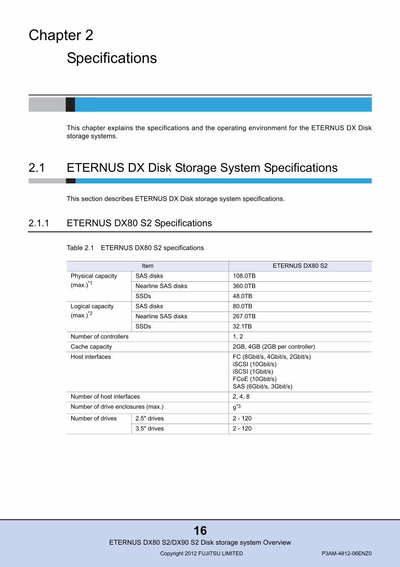
Table 2.1 ETERNUS DX80 S2 specifications
Item ETERNUS DX80 S2
Physical capacity (max.)*1
SAS disks 108.0TB
Nearline SAS disks 360.0TB
SSDs 48.0TB
Logical capacity (max.)*2
SAS disks 80.0TB
Nearline SAS disks 267.0TB
SSDs 32.1TB
Number of controllers 1, 2
Cache capacity 2GB, 4GB (2GB per controller)
Host interfaces FC (8Gbit/s, 4Gbit/s, 2Gbit/s)iSCSI (10Gbit/s)iSCSI (1Gbit/s)FCoE (10Gbit/s)SAS (6Gbit/s, 3Gbit/s)
Number of host interfaces 2, 4, 8
Number of drive enclosures (max.) 9*3
Number of drives 2.5" drives 2 - 120
3.5" drives 2 - 120
ETERNUS DX80 S2/DX90 S2 Disk storage system OverviewCopyright 2012 FUJITSU LIMITED P3AM-4812-06ENZ0
16
Chapter 2 Specifications 2.1 ETERNUS DX Disk Storage System Specifications
*1: Physical capacity is calculated based on the assumption that 1TB=1,000GB and 1GB=1,000MB.*2: Logical capacity is calculated based on the assumption that 1TB=1,024GB, 1GB=1,024MB and that drives
are formatted in a RAID5 configuration. The available capacity depends on the RAID configuration.*3: 3.5" type and 2.5" type drive enclosures can be installed together. *4: Two ports for each controller*5: One port for each controller. Power synchronization is performed via a power synchronized unit.
2.1.2 ETERNUS DX90 S2 Specifications
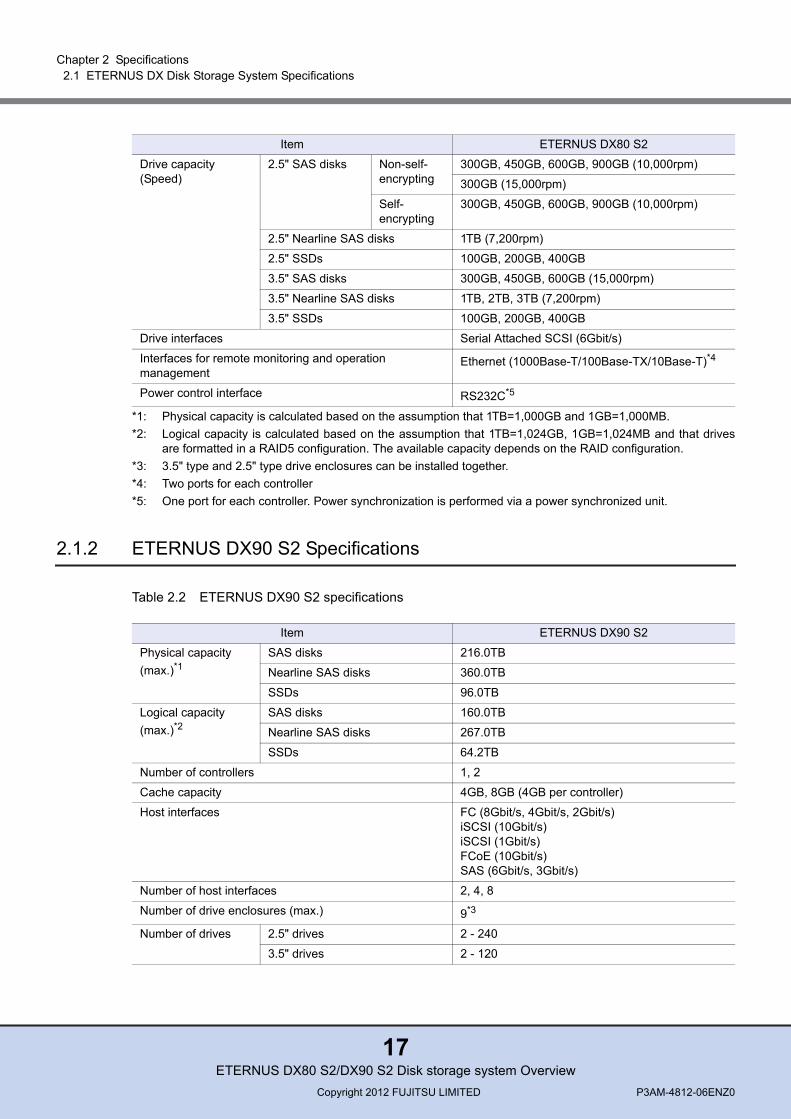
Table 2.2 ETERNUS DX90 S2 specifications
Drive capacity(Speed)
2.5" SAS disks Non-self-encrypting
300GB, 450GB, 600GB, 900GB (10,000rpm)
300GB (15,000rpm)
Self-encrypting
300GB, 450GB, 600GB, 900GB (10,000rpm)
2.5" Nearline SAS disks 1TB (7,200rpm)
2.5" SSDs 100GB, 200GB, 400GB
3.5" SAS disks 300GB, 450GB, 600GB (15,000rpm)
3.5" Nearline SAS disks 1TB, 2TB, 3TB (7,200rpm)
3.5" SSDs 100GB, 200GB, 400GB
Drive interfaces Serial Attached SCSI (6Gbit/s)
Interfaces for remote monitoring and operation management
Ethernet (1000Base-T/100Base-TX/10Base-T)*4
Power control interface RS232C*5
Item ETERNUS DX80 S2
Item ETERNUS DX90 S2
Physical capacity (max.)*1
SAS disks 216.0TB
Nearline SAS disks 360.0TB
SSDs 96.0TB
Logical capacity (max.)*2
SAS disks 160.0TB
Nearline SAS disks 267.0TB
SSDs 64.2TB
Number of controllers 1, 2
Cache capacity 4GB, 8GB (4GB per controller)
Host interfaces FC (8Gbit/s, 4Gbit/s, 2Gbit/s)iSCSI (10Gbit/s)iSCSI (1Gbit/s)FCoE (10Gbit/s)SAS (6Gbit/s, 3Gbit/s)
Number of host interfaces 2, 4, 8
Number of drive enclosures (max.) 9*3
Number of drives 2.5" drives 2 - 240
3.5" drives 2 - 120
ETERNUS DX80 S2/DX90 S2 Disk storage system OverviewCopyright 2012 FUJITSU LIMITED P3AM-4812-06ENZ0
17

Chapter 2 Specifications 2.2 Function Specifications
*1: Physical capacity is calculated based on the assumption that 1TB=1,000GB and 1GB=1,000MB.*2: Logical capacity is calculated based on the assumption that 1TB=1,024GB, 1GB=1,024MB and that drives
are formatted in a RAID5 configuration. The available capacity depends on the RAID configuration.*3: 3.5" type and 2.5" type drive enclosures can be installed together. *4: Two ports for each controller*5: One port for each controller. Power synchronization is performed via a power synchronized unit.
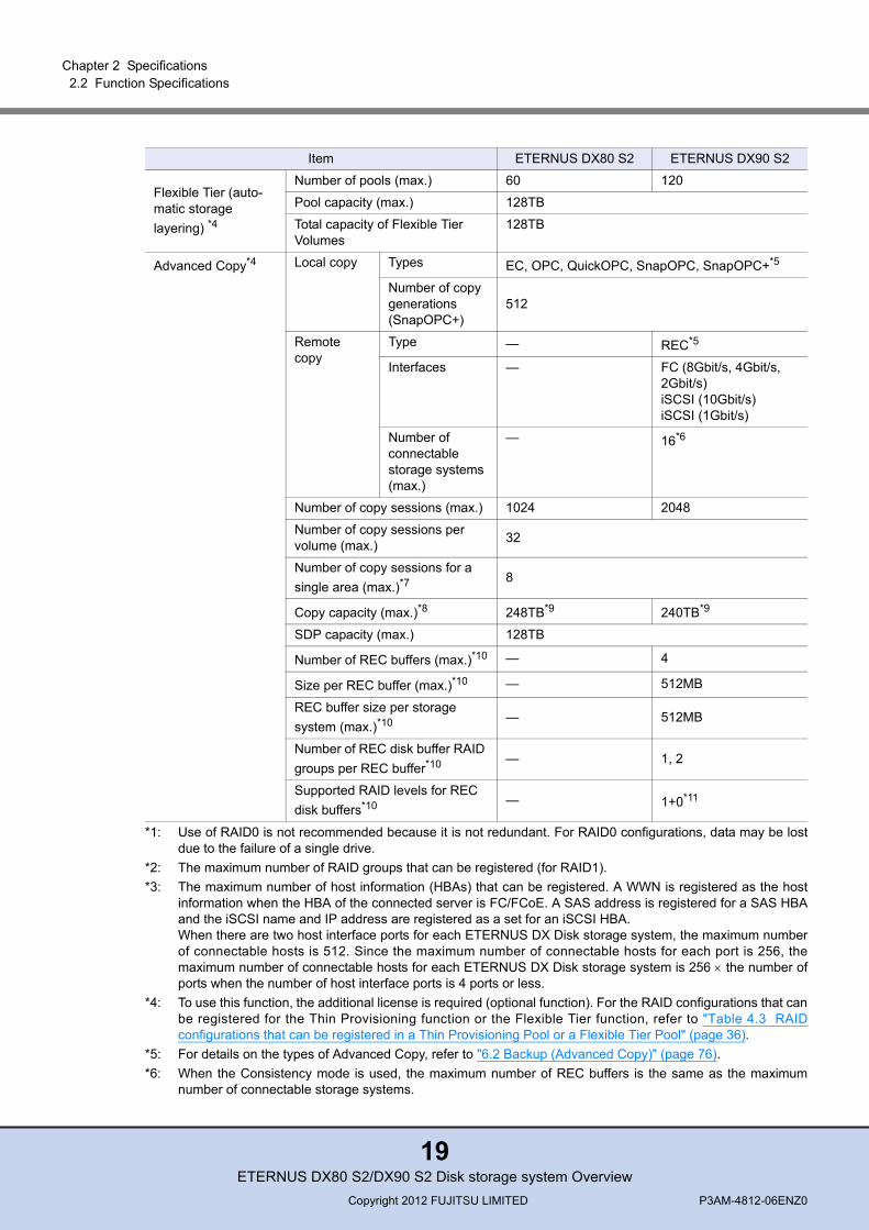
2.2 Function Specifications
This section contains the specifications of the functions for the ETERNUS DX Disk storage system.
Table 2.3 ETERNUS DX80 S2/DX90 S2 function specifications
Drive capacity(Speed)
2.5" SAS disks Non-self-encrypting
300GB, 450GB, 600GB, 900GB (10,000rpm)
300GB (15,000rpm)
Self-encrypting
300GB, 450GB, 600GB, 900GB (10,000rpm)
2.5" Nearline SAS disks 1TB (7,200rpm)
2.5" SSDs 100GB, 200GB, 400GB
3.5" SAS disks 300GB, 450GB, 600GB (15,000rpm)
3.5" Nearline SAS disks 1TB, 2TB, 3TB (7,200rpm)
3.5" SSDs 100GB, 200GB, 400GB
Drive interfaces Serial Attached SCSI (6Gbit/s)
Interfaces for remote monitoring and operation management
Ethernet (1000Base-T/100Base-TX/10Base-T)*4
Power control interface RS232C*5
Item ETERNUS DX90 S2
Item ETERNUS DX80 S2 ETERNUS DX90 S2
Supported RAID levels 0*1, 1, 1+0, 5, 5+0, 6
RAID groups Number of RAID groups (max.)*2 60 120
Number of volumes per RAID group 128
Volumes Number of volumes (max.) 2048 4096
Volume capacity (max.) 128TB
Number of connectable hosts (max.)*3
per storage system 1024
per port 256
Thin Provisioning*4 Number of pools (max.) 60 120
Pool capacity (max.) 128TB
Total capacity of Thin Provisioning Volumes
128TB
ETERNUS DX80 S2/DX90 S2 Disk storage system OverviewCopyright 2012 FUJITSU LIMITED P3AM-4812-06ENZ0
18
Chapter 2 Specifications 2.2 Function Specifications
*1: Use of RAID0 is not recommended because it is not redundant. For RAID0 configurations, data may be lostdue to the failure of a single drive.
*2: The maximum number of RAID groups that can be registered (for RAID1).*3: The maximum number of host information (HBAs) that can be registered. A WWN is registered as the host
information when the HBA of the connected server is FC/FCoE. A SAS address is registered for a SAS HBAand the iSCSI name and IP address are registered as a set for an iSCSI HBA.When there are two host interface ports for each ETERNUS DX Disk storage system, the maximum numberof connectable hosts is 512. Since the maximum number of connectable hosts for each port is 256, themaximum number of connectable hosts for each ETERNUS DX Disk storage system is 256 × the number ofports when the number of host interface ports is 4 ports or less.
*4: To use this function, the additional license is required (optional function). For the RAID configurations that canbe registered for the Thin Provisioning function or the Flexible Tier function, refer to "Table 4.3 RAIDconfigurations that can be registered in a Thin Provisioning Pool or a Flexible Tier Pool" (page 36).
*5: For details on the types of Advanced Copy, refer to "6.2 Backup (Advanced Copy)" (page 76).*6: When the Consistency mode is used, the maximum number of REC buffers is the same as the maximum
number of connectable storage systems.
Flexible Tier (auto-matic storage layering) *4
Number of pools (max.) 60 120
Pool capacity (max.) 128TB
Total capacity of Flexible Tier Volumes
128TB
Advanced Copy*4 Local copy Types EC, OPC, QuickOPC, SnapOPC, SnapOPC+*5
Number of copy generations(SnapOPC+)
512
Remote copy
Type — REC*5
Interfaces — FC (8Gbit/s, 4Gbit/s, 2Gbit/s)iSCSI (10Gbit/s)iSCSI (1Gbit/s)
Number of connectable storage systems (max.)
— 16*6
Number of copy sessions (max.) 1024 2048
Number of copy sessions per volume (max.) 32
Number of copy sessions for a single area (max.)*7
8
Copy capacity (max.)*8 248TB*9 240TB*9
SDP capacity (max.) 128TB
Number of REC buffers (max.)*10 — 4
Size per REC buffer (max.)*10 — 512MB
REC buffer size per storage system (max.)*10 — 512MB
Number of REC disk buffer RAID groups per REC buffer*10 — 1, 2
Supported RAID levels for REC disk buffers*10 — 1+0*11
Item ETERNUS DX80 S2 ETERNUS DX90 S2
ETERNUS DX80 S2/DX90 S2 Disk storage system OverviewCopyright 2012 FUJITSU LIMITED P3AM-4812-06ENZ0
19

Chapter 2 Specifications 2.2 Function Specifications
*7: For details on the maximum number of copy sessions for a single area, refer to the multiple copy section in"6.2.3 Available Advanced Copy Combinations" (page 83).
*8: This value is the total capacity of data that can be copied simultaneously. The copy capacity differs depend-ing on the settings and the copy conditions. The following formula can be used to calculate the copy capacity:Executable copy capacity [GB] = (S[MB] × 1024 ÷ 8[KB] − N) × M ÷ 2 (round down the result)S: copy table size, N: the number of sessions, M: bitmap ratioFor details about the setting, refer to "ETERNUS Web GUI User’s Guide".
*9: This value was calculated when:- The maximum copy table size was set for the ETERNUS DX Disk storage system.- The maximum bitmap ratio was set for the ETERNUS DX Disk storage system. - The maximum number of the sessions was set for the ETERNUS DX Disk storage system. - Restore OPC was not used.
*10: For details on REC buffers and REC disk buffers, refer to the Consistency mode section in "6.2.2 RemoteCopy" (page 80).
*11: Four (2+2) or eight (4+4) drives are required as configuration drives.
ETERNUS DX80 S2/DX90 S2 Disk storage system OverviewCopyright 2012 FUJITSU LIMITED P3AM-4812-06ENZ0
20

Chapter 2 Specifications 2.3 Supported OSes
2.3 Supported OSes
This section explains the operating environment that is required for the ETERNUS DX Disk storagesystem operation.
Servers and OSes that are supported by the ETERNUS DX Disk storage system are shown below.For the possible combinations of servers, Host Bus Adapters (HBAs), and driver software that can beused, refer to "Server Support Matrix" by accessing the URL that is described in "README" on theDocumentation CD provided with the ETERNUS DX Disk storage system.
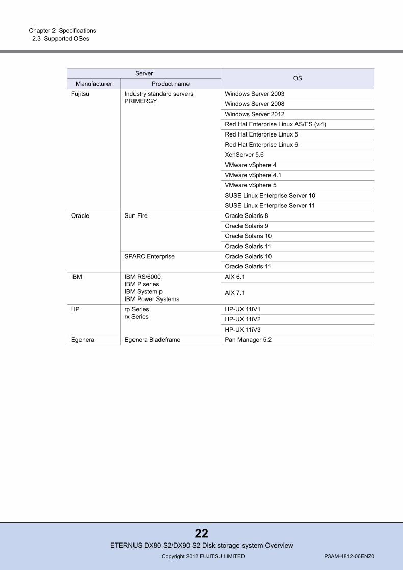
■ FC interface
Table 2.4 Supported servers and OSes (FC interface)
ServerOS
Manufacturer Product name
Fujitsu Mission critical IA serversPRIMEQUEST400/500/500A series
Windows Server 2003
Windows Server 2008
Red Hat Enterprise Linux AS (v.4)
Red Hat Enterprise Linux 5
Mission critical IA serversPRIMEQUEST 1000 series
Windows Server 2003
Windows Server 2008
Windows Server 2012
Red Hat Enterprise Linux 5
Red Hat Enterprise Linux 6
VMware vSphere 4
VMware vSphere 4.1
VMware vSphere 5
UNIX serversSPARC Enterprise
Oracle Solaris 10
Oracle Solaris 11
UNIX serversPRIMEPOWERSun Fire
Oracle Solaris 8
Oracle Solaris 9
Oracle Solaris 10
ETERNUS DX80 S2/DX90 S2 Disk storage system OverviewCopyright 2012 FUJITSU LIMITED P3AM-4812-06ENZ0
21
Chapter 2 Specifications 2.3 Supported OSes
Fujitsu Industry standard serversPRIMERGY
Windows Server 2003
Windows Server 2008
Windows Server 2012
Red Hat Enterprise Linux AS/ES (v.4)
Red Hat Enterprise Linux 5
Red Hat Enterprise Linux 6
XenServer 5.6
VMware vSphere 4
VMware vSphere 4.1
VMware vSphere 5
SUSE Linux Enterprise Server 10
SUSE Linux Enterprise Server 11
Oracle Sun Fire Oracle Solaris 8
Oracle Solaris 9
Oracle Solaris 10
Oracle Solaris 11
SPARC Enterprise Oracle Solaris 10
Oracle Solaris 11
IBM IBM RS/6000IBM P seriesIBM System pIBM Power Systems
AIX 6.1
AIX 7.1
HP rp Seriesrx Series
HP-UX 11iV1
HP-UX 11iV2
HP-UX 11iV3
Egenera Egenera Bladeframe Pan Manager 5.2
ServerOS
Manufacturer Product name
ETERNUS DX80 S2/DX90 S2 Disk storage system OverviewCopyright 2012 FUJITSU LIMITED P3AM-4812-06ENZ0
22
Chapter 2 Specifications 2.3 Supported OSes
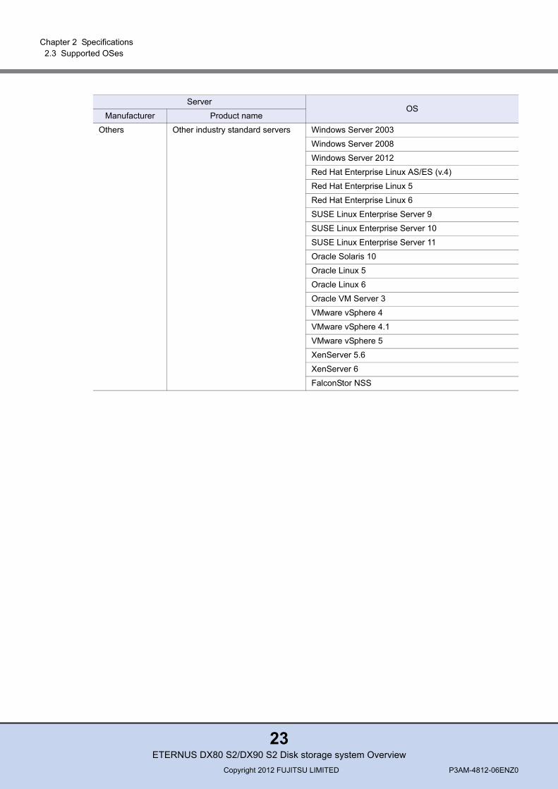
Others Other industry standard servers Windows Server 2003
Windows Server 2008
Windows Server 2012
Red Hat Enterprise Linux AS/ES (v.4)
Red Hat Enterprise Linux 5
Red Hat Enterprise Linux 6
SUSE Linux Enterprise Server 9
SUSE Linux Enterprise Server 10
SUSE Linux Enterprise Server 11
Oracle Solaris 10
Oracle Linux 5
Oracle Linux 6
Oracle VM Server 3
VMware vSphere 4
VMware vSphere 4.1
VMware vSphere 5
XenServer 5.6
XenServer 6
FalconStor NSS
ServerOS
Manufacturer Product name
ETERNUS DX80 S2/DX90 S2 Disk storage system OverviewCopyright 2012 FUJITSU LIMITED P3AM-4812-06ENZ0
23
Chapter 2 Specifications 2.3 Supported OSes
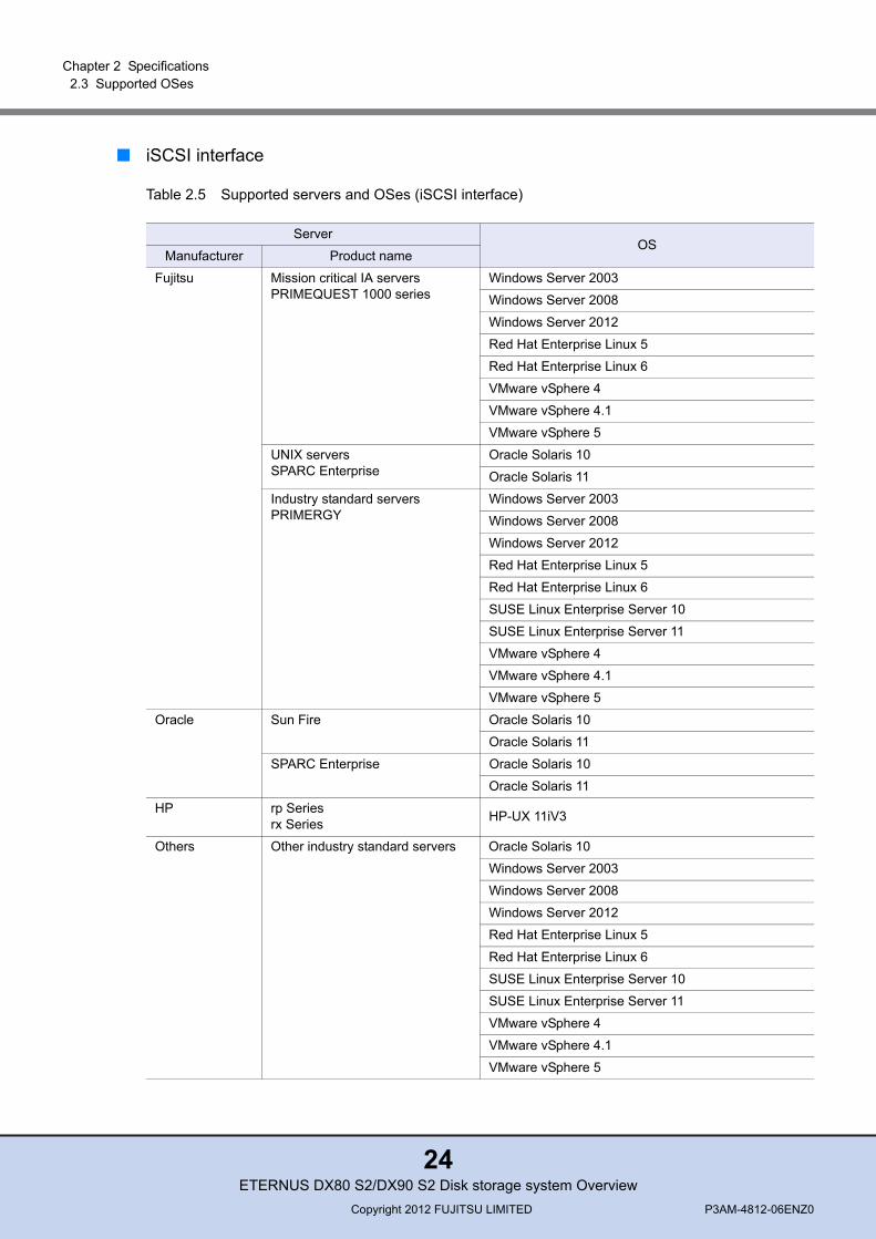
■ iSCSI interface
Table 2.5 Supported servers and OSes (iSCSI interface)
ServerOS
Manufacturer Product name
Fujitsu Mission critical IA serversPRIMEQUEST 1000 series
Windows Server 2003
Windows Server 2008
Windows Server 2012
Red Hat Enterprise Linux 5
Red Hat Enterprise Linux 6
VMware vSphere 4
VMware vSphere 4.1
VMware vSphere 5
UNIX serversSPARC Enterprise
Oracle Solaris 10
Oracle Solaris 11
Industry standard serversPRIMERGY
Windows Server 2003
Windows Server 2008
Windows Server 2012
Red Hat Enterprise Linux 5
Red Hat Enterprise Linux 6
SUSE Linux Enterprise Server 10
SUSE Linux Enterprise Server 11
VMware vSphere 4
VMware vSphere 4.1
VMware vSphere 5
Oracle Sun Fire Oracle Solaris 10
Oracle Solaris 11
SPARC Enterprise Oracle Solaris 10
Oracle Solaris 11
HP rp Seriesrx Series HP-UX 11iV3
Others Other industry standard servers Oracle Solaris 10
Windows Server 2003
Windows Server 2008
Windows Server 2012
Red Hat Enterprise Linux 5
Red Hat Enterprise Linux 6
SUSE Linux Enterprise Server 10
SUSE Linux Enterprise Server 11
VMware vSphere 4
VMware vSphere 4.1
VMware vSphere 5
ETERNUS DX80 S2/DX90 S2 Disk storage system OverviewCopyright 2012 FUJITSU LIMITED P3AM-4812-06ENZ0
24
Chapter 2 Specifications 2.3 Supported OSes
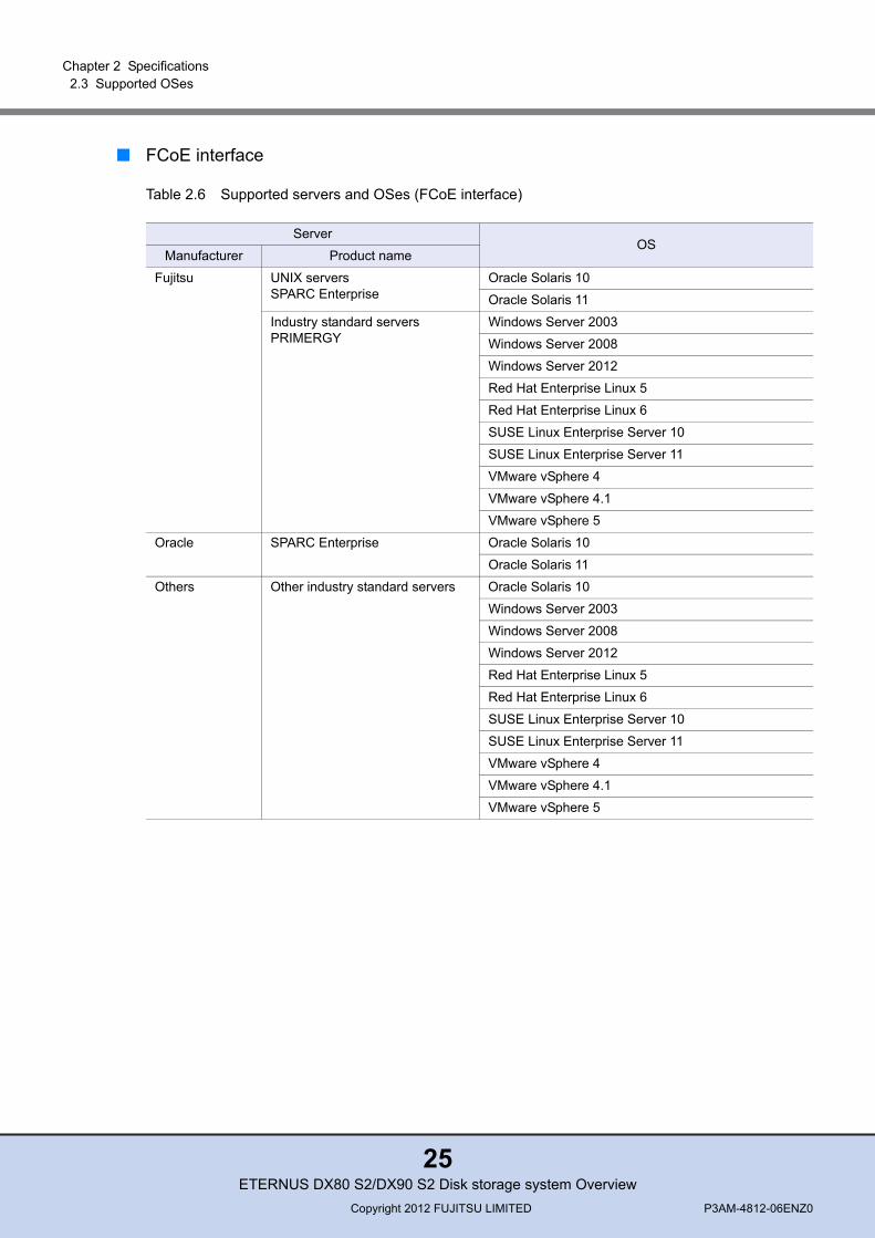
■ FCoE interface
Table 2.6 Supported servers and OSes (FCoE interface)
ServerOS
Manufacturer Product name
Fujitsu UNIX serversSPARC Enterprise
Oracle Solaris 10
Oracle Solaris 11
Industry standard serversPRIMERGY
Windows Server 2003
Windows Server 2008
Windows Server 2012
Red Hat Enterprise Linux 5
Red Hat Enterprise Linux 6
SUSE Linux Enterprise Server 10
SUSE Linux Enterprise Server 11
VMware vSphere 4
VMware vSphere 4.1
VMware vSphere 5
Oracle SPARC Enterprise Oracle Solaris 10
Oracle Solaris 11
Others Other industry standard servers Oracle Solaris 10
Windows Server 2003
Windows Server 2008
Windows Server 2012
Red Hat Enterprise Linux 5
Red Hat Enterprise Linux 6
SUSE Linux Enterprise Server 10
SUSE Linux Enterprise Server 11
VMware vSphere 4
VMware vSphere 4.1
VMware vSphere 5
ETERNUS DX80 S2/DX90 S2 Disk storage system OverviewCopyright 2012 FUJITSU LIMITED P3AM-4812-06ENZ0
25
Chapter 2 Specifications 2.3 Supported OSes
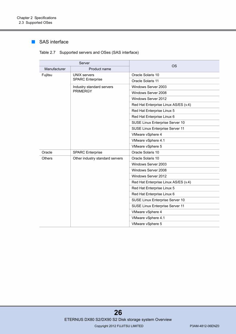
■ SAS interface
Table 2.7 Supported servers and OSes (SAS interface)
ServerOS
Manufacturer Product name
Fujitsu UNIX serversSPARC Enterprise
Oracle Solaris 10
Oracle Solaris 11
Industry standard serversPRIMERGY
Windows Server 2003
Windows Server 2008
Windows Server 2012
Red Hat Enterprise Linux AS/ES (v.4)
Red Hat Enterprise Linux 5
Red Hat Enterprise Linux 6
SUSE Linux Enterprise Server 10
SUSE Linux Enterprise Server 11
VMware vSphere 4
VMware vSphere 4.1
VMware vSphere 5
Oracle SPARC Enterprise Oracle Solaris 10
Others Other industry standard servers Oracle Solaris 10
Windows Server 2003
Windows Server 2008
Windows Server 2012
Red Hat Enterprise Linux AS/ES (v.4)
Red Hat Enterprise Linux 5
Red Hat Enterprise Linux 6
SUSE Linux Enterprise Server 10
SUSE Linux Enterprise Server 11
VMware vSphere 4
VMware vSphere 4.1
VMware vSphere 5
ETERNUS DX80 S2/DX90 S2 Disk storage system OverviewCopyright 2012 FUJITSU LIMITED P3AM-4812-06ENZ0
26
Chapter 3
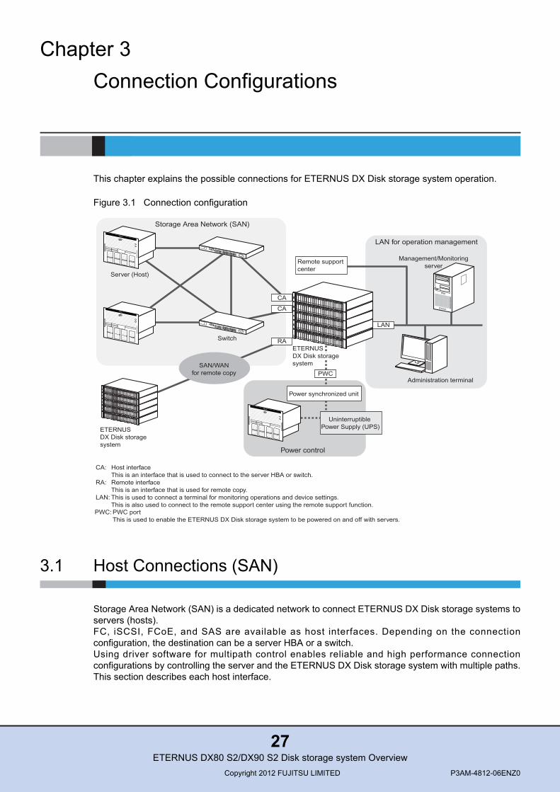
Connection ConfigurationsThis chapter explains the possible connections for ETERNUS DX Disk storage system operation.
Figure 3.1 Connection configuration
3.1 Host Connections (SAN)
Storage Area Network (SAN) is a dedicated network to connect ETERNUS DX Disk storage systems toservers (hosts).FC, iSCSI, FCoE, and SAS are available as host interfaces. Depending on the connectionconfiguration, the destination can be a server HBA or a switch.Using driver software for multipath control enables reliable and high performance connectionconfigurations by controlling the server and the ETERNUS DX Disk storage system with multiple paths.This section describes each host interface.
Administration terminal
Management/Monitoringserver
LAN
LAN for operation management
Remote supportcenter
CA
CA
RA
SAN/WANfor remote copy
Storage Area Network (SAN)
Server (Host)
ETERNUSDX Disk storagesystem
Switch
Host interfaceThis is an interface that is used to connect to the server HBA or switch.Remote interfaceThis is an interface that is used for remote copy.This is used to connect a terminal for monitoring operations and device settings.This is also used to connect to the remote support center using the remote support function.
CA:
RA:
LAN:
PWC
Power synchronized unit
Power control
Uninterruptible Power Supply (UPS)
ETERNUSDX Disk storagesystem
PWC portThis is used to enable the ETERNUS DX Disk storage system to be powered on and off with servers.
PWC:
ETERNUS DX80 S2/DX90 S2 Disk storage system OverviewCopyright 2012 FUJITSU LIMITED P3AM-4812-06ENZ0
27
Chapter 3 Connection Configurations 3.2 Remote Connections (SAN/WAN)
● FC (Fibre Channel)
FC enables high speed data transfer over long distances by using optical fibers and coaxial cables.FC is used for database servers where enhanced scalability and high performance are required.
● iSCSI
iSCSI is a communication protocol that transfers SCSI commands by encapsulating them in IPpackets over Ethernet. Since iSCSI can be installed at a lower cost and the network configuration iseasier to change than FC, iSCSI is commonly used by divisions of large companies and by smalland medium-sized companies where scalability and cost-effectiveness are valued overperformance.
● FCoE
Since Fibre Channel over Ethernet (FCoE) encapsulates FC frames and transfers them overEthernet, a LAN environment and an FC-SAN environment can be integrated. When there arenetworks for multiple I/O interfaces (e.g. in a data center), the networks can be integrated andmanaged.
● SAS
SAS (Serial Attached SCSI) is a serial transfer host interface that is as reliable as the normal(parallel) SCSI interface.SAS is commonly used for small-sized systems where performance and cost-effectiveness arevalued over scalability.
3.2 Remote Connections (SAN/WAN)
Data backup (remote copy) can be performed without using servers by connecting ETERNUS DX Diskstorage systems. Remote copy is a function that is used to mirror drive data, create a snapshot, andback up data between separate ETERNUS DX Disk storage systems.Remote copy supports FC and iSCSI interfaces. SAN and WAN (wide area network) are used totransfer data between ETERNUS DX Disk storage systems.This section describes each remote interface.
● FC (Fibre Channel)
Data can be copied and operated by taking advantage of the high speed and reliability of FC. Bycompressing the data that is to be transferred using a network device, data can be transferred athigh speeds.
● iSCSI
Remote copy can be performed without FCIP converters when an IP line is used.
ETERNUS DX80 S2/DX90 S2 Disk storage system OverviewCopyright 2012 FUJITSU LIMITED P3AM-4812-06ENZ0
28
Chapter 3 Connection Configurations 3.3 LAN
3.3 LAN
For ETERNUS DX Disk storage systems, operations such as RAID configuration, operationmanagement, and system maintenance are performed via the LAN.The functions of the management/monitoring server on the LAN, which include SNMP (devicemonitoring), SMTP (sending e-mails), NTP (time correction), syslog (sending logs), and RADIUS (userauthentication), can also be used.Any errors that occur in the ETERNUS DX Disk storage system are notified to the remote supportcenter when remote support is used.
3.4 Power Synchronization
Powering the ETERNUS DX Disk storage system on and off can be automatically controlled with aserver.
● Power synchronized unit
A power synchronized unit detects changes in the AC power output of the Uninterruptible PowerSupply (UPS) unit that is connected to the server and automatically turns on and off the ETERNUSDX Disk storage system.
ETERNUS DX80 S2/DX90 S2 Disk storage system OverviewCopyright 2012 FUJITSU LIMITED P3AM-4812-06ENZ0
29
Chapter 4
System ConfigurationThis chapter explains points to note before configuring a system using the ETERNUS DX Disk storagesystem.
4.1 RAID Levels
This section explains RAID group configuration and the supported RAID levels and usage (RAID levelselection criteria).
■ Supported RAID levels and mechanismThe ETERNUS DX Disk storage system supports the following RAID levels.
• RAID0 (striping)• RAID1 (mirroring)• RAID1+0 (striping of pairs of drives for mirroring)• RAID5 (striping with distributed parity blocks)• RAID5+0 (double striping with distributed parity)• RAID6 (striping with distributed double parity blocks)
CAUTIONDo
• Remember that a RAID0 configuration is not redundant. This means that if a RAID0 drive fails, the data will not be recoverable.Therefore, using a RAID1, RAID1+0, RAID5, RAID5+0, or RAID6 configuration is recommended.
ETERNUS DX80 S2/DX90 S2 Disk storage system OverviewCopyright 2012 FUJITSU LIMITED P3AM-4812-06ENZ0
30

Chapter 4 System Configuration 4.1 RAID Levels
Each RAID level description is shown below.
● RAID0 (striping)
Data is split in unit of blocks and stored across multiple drives.
Figure 4.1 RAID0 concept
● RAID1 (mirroring)
RAID1 stores the same data on two duplicated drives at the same time.If one drive fails, other drive continues operation.
Figure 4.2 RAID1 concept
AC
BD
Data writing request
HDD0 HDD1
A B C D
AB
CD
A B C D
Data writing request
AB
CD
HDD0 HDD1
ETERNUS DX80 S2/DX90 S2 Disk storage system OverviewCopyright 2012 FUJITSU LIMITED P3AM-4812-06ENZ0
31
Chapter 4 System Configuration 4.1 RAID Levels
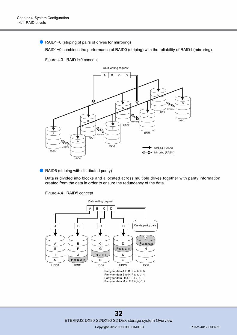
● RAID1+0 (striping of pairs of drives for mirroring)
RAID1+0 combines the performance of RAID0 (striping) with the reliability of RAID1 (mirroring).
Figure 4.3 RAID1+0 concept
● RAID5 (striping with distributed parity)
Data is divided into blocks and allocated across multiple drives together with parity informationcreated from the data in order to ensure the redundancy of the data.
Figure 4.4 RAID5 concept
HDD3
HDD7
D
D’
HDD2
HDD6
C
C’
HDD1
HDD5
B
B’
HDD0
HDD4
A
A’
Striping (RAID0)
Mirroring (RAID1)
Data writing request
A B C D
Mirroring
Mirroring
Mirroring
Mirroring
AE
IM
A B C D
Data writing request
BF
JP M, N, O, P
CG
P I, J, K, L
N
DP E, F, G, H
KO
H
LP
Create parity data
P A, B, C, D
A B DC
HDD0 HDD1 HDD2 HDD3 HDD4
Parity for data A to D:Parity for data E to H:Parity for data I to L:Parity for data M to P:
P A, B, C, DP E, F, G, HP I, J, K, LP M, N, O, P
ETERNUS DX80 S2/DX90 S2 Disk storage system OverviewCopyright 2012 FUJITSU LIMITED P3AM-4812-06ENZ0
32
Chapter 4 System Configuration 4.1 RAID Levels
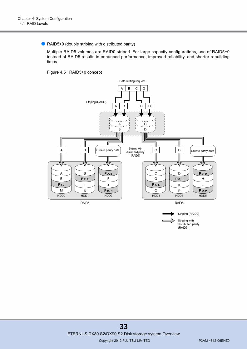
● RAID5+0 (double striping with distributed parity)
Multiple RAID5 volumes are RAID0 striped. For large capacity configurations, use of RAID5+0instead of RAID5 results in enhanced performance, improved reliability, and shorter rebuildingtimes.
Figure 4.5 RAID5+0 concept
Striping withdistributed parity(RAID5)
Striping (RAID0)
AE
B
I
FP A, B
P M, N
CG H
P C, D
P O, P
HDD0 HDD1 HDD2 HDD3 HDD4 HDD5
D
KP K, L
Striping (RAID0)
Striping withdistributed parity
(RAID5)
J L
M N O P
P E, F
P I, J
P G, H
RAID5 RAID5
A B Create parity data D Create parity dataC
Data writing request
AB
CD
A B C D
A B C D
ETERNUS DX80 S2/DX90 S2 Disk storage system OverviewCopyright 2012 FUJITSU LIMITED P3AM-4812-06ENZ0
33
Chapter 4 System Configuration 4.1 RAID Levels
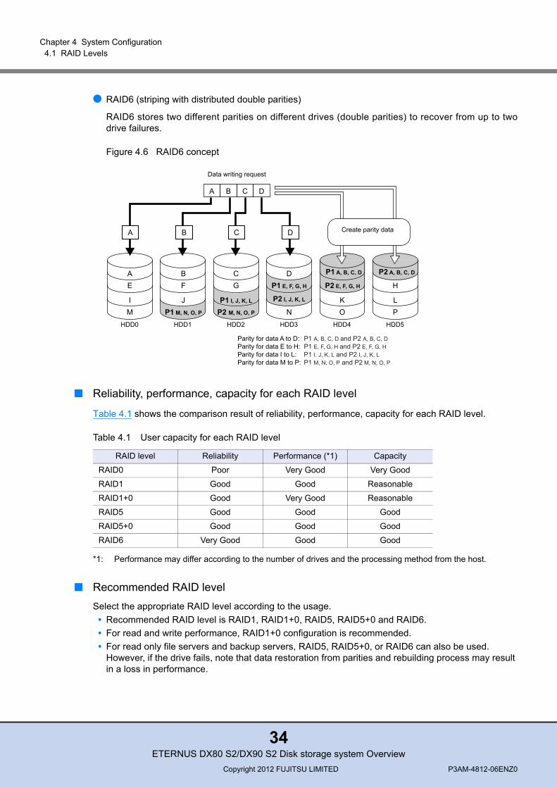
● RAID6 (striping with distributed double parities)
RAID6 stores two different parities on different drives (double parities) to recover from up to twodrive failures.
Figure 4.6 RAID6 concept
■ Reliability, performance, capacity for each RAID level
Table 4.1 shows the comparison result of reliability, performance, capacity for each RAID level.
Table 4.1 User capacity for each RAID level
*1: Performance may differ according to the number of drives and the processing method from the host.
■ Recommended RAID levelSelect the appropriate RAID level according to the usage.
• Recommended RAID level is RAID1, RAID1+0, RAID5, RAID5+0 and RAID6.• For read and write performance, RAID1+0 configuration is recommended.• For read only file servers and backup servers, RAID5, RAID5+0, or RAID6 can also be used.
However, if the drive fails, note that data restoration from parities and rebuilding process may result in a loss in performance.
P2 M, N, O, P
P2 I, J, K, L
AE
IM
A B C D
Data writing request
BF
JP1 M, N, O, P
CG
P1 I, J, K, L
DP1 E, F, G, H P2 E, F, G, H
NKO
P1 A, B, C, D
H
LP
P2 A, B, C, D
A B DC Create parity data
HDD0 HDD1 HDD2 HDD3 HDD4 HDD5
Parity for data A to D:Parity for data E to H:Parity for data I to L:Parity for data M to P:
P1 A, B, C, D and P2 A, B, C, DP1 E, F, G, H and P2 E, F, G, HP1 I, J, K, L and P2 I, J, K, LP1 M, N, O, P and P2 M, N, O, P
RAID level Reliability Performance (*1) Capacity
RAID0 Poor Very Good Very Good
RAID1 Good Good Reasonable
RAID1+0 Good Very Good Reasonable
RAID5 Good Good Good
RAID5+0 Good Good Good
RAID6 Very Good Good Good
ETERNUS DX80 S2/DX90 S2 Disk storage system OverviewCopyright 2012 FUJITSU LIMITED P3AM-4812-06ENZ0
34

Chapter 4 System Configuration 4.2 RAID Groups
4.2 RAID Groups
This section explains RAID groups.
A RAID group is a group of drives. It is a unit that configures RAID. Multiple RAID groups with the sameRAID level or multiple RAID groups with different RAID levels can be set together in the ETERNUS DXDisk storage system. After a RAID group is created, RAID levels can be changed and drives can beadded.The same size drives (2.5", 3.5") and the same kind of drives (SAS, Nearline SAS, SSD, or SED) mustbe used to configure a RAID group.
Figure 4.7 Example of a RAID group
Table 4.2 shows the recommended number of drives that configure a RAID group.
Table 4.2 Recommended number of drives per RAID group
*1: D = Data, M = Mirror, P = Parity
RAID level Number of configuration drives Recommended number of drives (*1)
RAID1 2 2(1D+1M)
RAID1+0 4 to 32 4(2D+2M), 6(3D+3M), 8(4D+4M), 10(5D+5M)
RAID5 3 to 16 3(2D+1P), 4(3D+1P), 5(4D+1P), 6(5D+1P)
RAID5+0 6 to 32 3(2D+1P) × 2, 4(3D+1P) × 2, 5(4D+1P) × 2, 6(5D+1P) × 2
RAID6 5 to 16 5(3D+2P), 6(4D+2P), 7(5D+2P)
RAID group 1 RAID group 2
SAS600GB
SAS600GB
SAS600GB
SAS600GB
SAS600GB
SSD200GB
SSD200GB
SSD200GB
SSD200GB
ETERNUS DX80 S2/DX90 S2 Disk storage system OverviewCopyright 2012 FUJITSU LIMITED P3AM-4812-06ENZ0
35

Chapter 4 System Configuration 4.2 RAID Groups
Table 4.3 RAID configurations that can be registered in a Thin Provisioning Pool or a Flexible Tier Pool
An assigned CM is allocated to each RAID group. For details, refer to "5.5.4 Assigned CMs" (page 68).
• Sequential access performance hardly varies with the number of drives for the RAID group.• Random access performance tends to be proportional to the number of drives for the RAID group.• Use of higher capacity drives will increase the time required for the drive rebuild process to
complete.• The higher the number of drives in a RAID5, RAID5+0, or RAID6 configuration, the longer the
period of time for data restoration and rebuilding processes from parities.• To use the Thin Provisioning function or the Flexible Tier function, the drive area of the virtual
volume is managed using a pool.The following table shows the RAID configurations that can be registered in a Thin Provisioning Pool or a Flexible Tier Pool.
RAID level Number of configuration drives
RAID0 (*1) 4(4D)
RAID1 2(1D+1M)
RAID1+0 4(2D+2M), 8(4D+4M), 16(8D+8M), 24(12D+12M)
RAID5 4(3D+1P), 5(4D+1P), 8(7D+1P), 9(8D+1P), 13(12D+1P)
RAID6 6(4D+2P), 8(6D+2P), 10(8D+2P)
*1: Use of RAID0 is not recommended because it is not redundant. For RAID0 configurations, data may belost due to the failure of a single drive.
For details about the Thin Provisioning function, refer to "6.1.1 Thin Provisioning" (page 73). For details about the Flexible Tier function, refer to "6.1.2 Flexible Tier (Automatic Storage Layering)" (page 74).
ETERNUS DX80 S2/DX90 S2 Disk storage system OverviewCopyright 2012 FUJITSU LIMITED P3AM-4812-06ENZ0
36

Chapter 4 System Configuration 4.3 Volumes
4.3 Volumes
This section explains volumes.Logical drive areas in RAID groups are called volumes.A volume is the basic RAID unit that can be recognized by the server.
Figure 4.8 Volume concept
A volume may be up to 128TB. However, the maximum capacity of volume varies depending on the OSof the server.A volume can be expanded or moved if required. Multiple volumes can be concatenated and treated asa single volume.
The types of volumes that are listed in the table below can be created in the ETERNUS DX Diskstorage system.
Table 4.4 Volumes that can be created
Type Usage Maximum capacity
Standard/Open This volume is used for normal usage, such as file systems and databases. The server recognizes it as a single logical unit.
128TB (*1)
Snap Data Volume (SDV) The area of this volume is used as the copy destination for SnapOPC/SnapOPC+. There is a SDV for each copy destination.
Approximately 0.1% of the SDV virtual capacity
Snap Data Pool Volume (SDPV)
This volume is used to configure the Snap Data Pool (SDP) area. The SDP capacity equals the total capacity of the SDPVs.A volume is supplied from a SDP when the amount of updates exceeds the capacity of the SDV.
2TB
Thin Provisioning Volume (TPV)
This virtual volume is created in a Thin Provisioning Pool area. 128TB (*2)
Flexible Tier Volume (FTV) This volume is a target volume for layering. Data is automatically redistributed in small block units according to the access frequency. An FTV belongs to a Flexible Tier Pool.
128TB (*2)
RAID group 1 RAID group 2
Volume 1
Volume 2Volume 3
ETERNUS DX80 S2/DX90 S2 Disk storage system OverviewCopyright 2012 FUJITSU LIMITED P3AM-4812-06ENZ0
37

Chapter 4 System Configuration 4.4 Drives
*1: When multiple volumes are concatenated using the LUN Concatenation function, the maximum capacity isalso 128TB.
*2: The maximum total capacity of volumes and the maximum pool capacity in the ETERNUS DX Disk storagesystem are also 128TB.
After a volume is created, formatting automatically starts. A server can access the volume while it isbeing formatted. Wait for the format to complete if high performance access is required for the volume.
4.4 Drives
The ETERNUS DX Disk storage system supports the latest drives that have the high-speed SerialAttached SCSI (6Gbit/s) interface.
SAS disks, Nearline SAS disks, and SSDs can be installed in the ETERNUS DX Disk storage system.Some drive types have a data encryption function.2.5" and 3.5" drive sizes are available.Since 2.5" drives are lighter and require less power than 3.5" drives, the total weight and powerconsumption when 2.5" drives are installed is less than when the same number of 3.5" drives isinstalled.When the data I/O count is compared based on the number of drives in an enclosure (2.5" drives: 24,3.5" drives: 12), the Input Output Per Second (IOPS) performance for each enclosure in a 2.5" driveconfiguration is superior to a 3.5" drive configuration since more 2.5" drives can be installed in anenclosure than 3.5" drives.
Wide Striping Volume (WSV)
This volume is created by concatenating distributed areas in from 2 to 64 RAID groups. Processing speed is fast because data access is distributed.
128TB
ODX Buffer This volume is a dedicated volume that is required to use the Offloaded Data Transfer (ODX) function of Windows Server 2012. When data is updated while a copy is being processed, this area is used to save the source data. The volume type is Standard/Open, TPV, or FTV.
1TB
Volumes have different stripe sizes that depend on the RAID level and the stripe depth parameter.The available user capacity can be fully utilized if an exact multiple of the stripe size is set for the volume size.If an exact multiple of the stripe size is not set for the volume size, unusable areas may remain.Refer to "ETERNUS Web GUI User's Guide" for details about the stripe size.
Type Usage Maximum capacity
ETERNUS DX80 S2/DX90 S2 Disk storage system OverviewCopyright 2012 FUJITSU LIMITED P3AM-4812-06ENZ0
38
Chapter 4 System Configuration 4.4 Drives
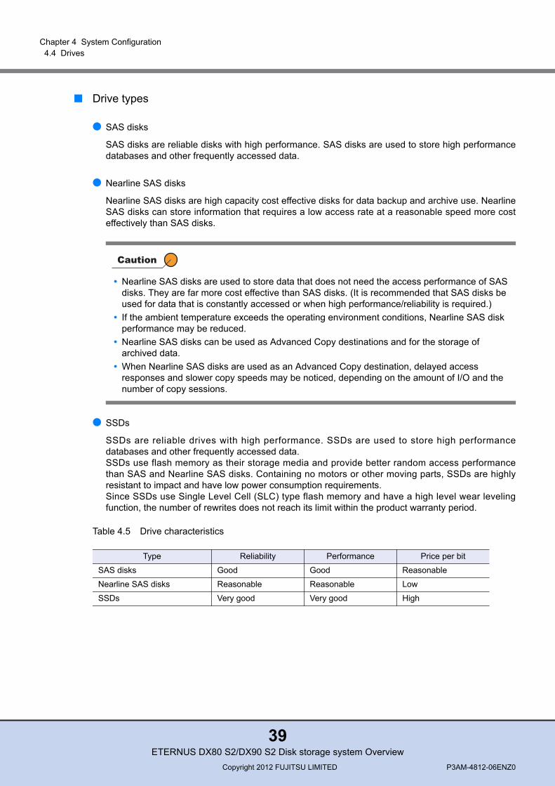
■ Drive types
● SAS disks
SAS disks are reliable disks with high performance. SAS disks are used to store high performancedatabases and other frequently accessed data.
● Nearline SAS disks
Nearline SAS disks are high capacity cost effective disks for data backup and archive use. NearlineSAS disks can store information that requires a low access rate at a reasonable speed more costeffectively than SAS disks.
● SSDs
SSDs are reliable drives with high performance. SSDs are used to store high performancedatabases and other frequently accessed data.SSDs use flash memory as their storage media and provide better random access performancethan SAS and Nearline SAS disks. Containing no motors or other moving parts, SSDs are highlyresistant to impact and have low power consumption requirements.Since SSDs use Single Level Cell (SLC) type flash memory and have a high level wear levelingfunction, the number of rewrites does not reach its limit within the product warranty period.
Table 4.5 Drive characteristics
• Nearline SAS disks are used to store data that does not need the access performance of SAS disks. They are far more cost effective than SAS disks. (It is recommended that SAS disks be used for data that is constantly accessed or when high performance/reliability is required.)
• If the ambient temperature exceeds the operating environment conditions, Nearline SAS disk performance may be reduced.
• Nearline SAS disks can be used as Advanced Copy destinations and for the storage of archived data.
• When Nearline SAS disks are used as an Advanced Copy destination, delayed access responses and slower copy speeds may be noticed, depending on the amount of I/O and the number of copy sessions.
Type Reliability Performance Price per bit
SAS disks Good Good Reasonable
Nearline SAS disks Reasonable Reasonable Low
SSDs Very good Very good High
ETERNUS DX80 S2/DX90 S2 Disk storage system OverviewCopyright 2012 FUJITSU LIMITED P3AM-4812-06ENZ0
39

Chapter 4 System Configuration 4.4 Drives
■ Encryption-compliantSelf Encrypting Drives (SEDs) are offered for the 2.5" SAS disks.
● Self Encrypting Drives (SEDs)
Each SED has the encryption function and stores an encryption key. Each ETERNUS DX Diskstorage system generates and has its own authentication key to access data.Only one type of authentication key can be registered in the ETERNUS DX Disk storage system forall of the installed SEDs.
4.4.1 User Capacity of Drives
Table 4.6 shows the user capacity for each drive.
Table 4.6 User capacity per drive
Some functions cannot be used with some types of drives.• Eco-mode cannot be set for SSDs.• Do not use different types of drives in a RAID group. Use the same type of drives when adding
capacity to a RAID group (RAID Migration, Logical Device Expansion).For details on each function, refer to "Chapter 5 Basic Functions" (page 46).
When using SEDs, the firmware version of the ETERNUS DX Disk storage system must be V10L20 or later. If the firmware version is earlier than V10L20, SED access performance may be reduced.The current firmware version can be checked via ETERNUS Web GUI or ETERNUS CLI. When upgrading firmware is required, contact your sales representative.
Product name (*1) User capacity
100GB SSD 92,672MB
200GB SSD 186,624MB
400GB SSD 374,528MB
300GB SAS disk 279,040MB
450GB SAS disk 419,072MB
600GB SAS disk 559,104MB
900GB SAS disk 839,168MB
1TB Nearline SAS disk 937,728MB
2TB Nearline SAS disk 1,866,240MB
3TB Nearline SAS disk 2,799,872MB
ETERNUS DX80 S2/DX90 S2 Disk storage system OverviewCopyright 2012 FUJITSU LIMITED P3AM-4812-06ENZ0
40
Chapter 4 System Configuration 4.4 Drives
*1: The capacity that is listed above for the product names of the drives is based on the assumption that 1MB =1,0002 bytes, while the user capacity per drive is based on the assumption that 1MB = 1,0242 bytes.Furthermore, OS file management overhead will reduce the actual usable capacity.The user capacity does not change even when the drive sizes (2.5"/3.5") are different, or whether or not thedrive is encryption-compliant (SED).
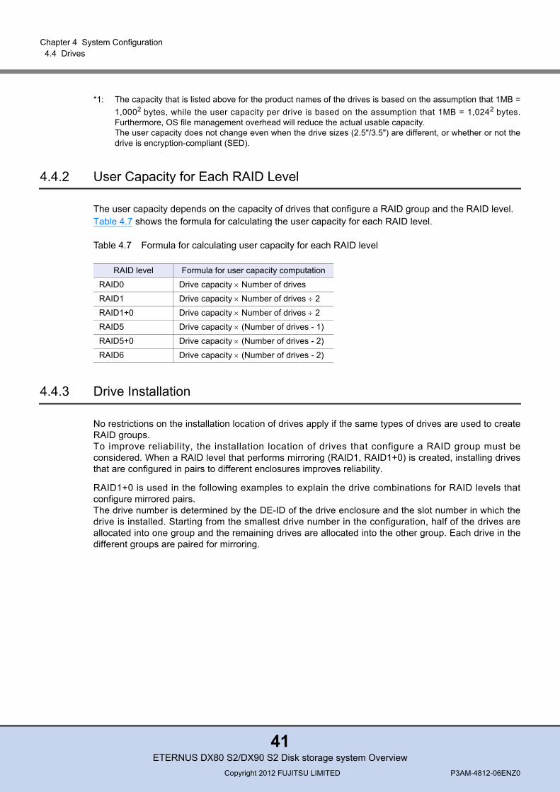
4.4.2 User Capacity for Each RAID Level
The user capacity depends on the capacity of drives that configure a RAID group and the RAID level.Table 4.7 shows the formula for calculating the user capacity for each RAID level.
Table 4.7 Formula for calculating user capacity for each RAID level
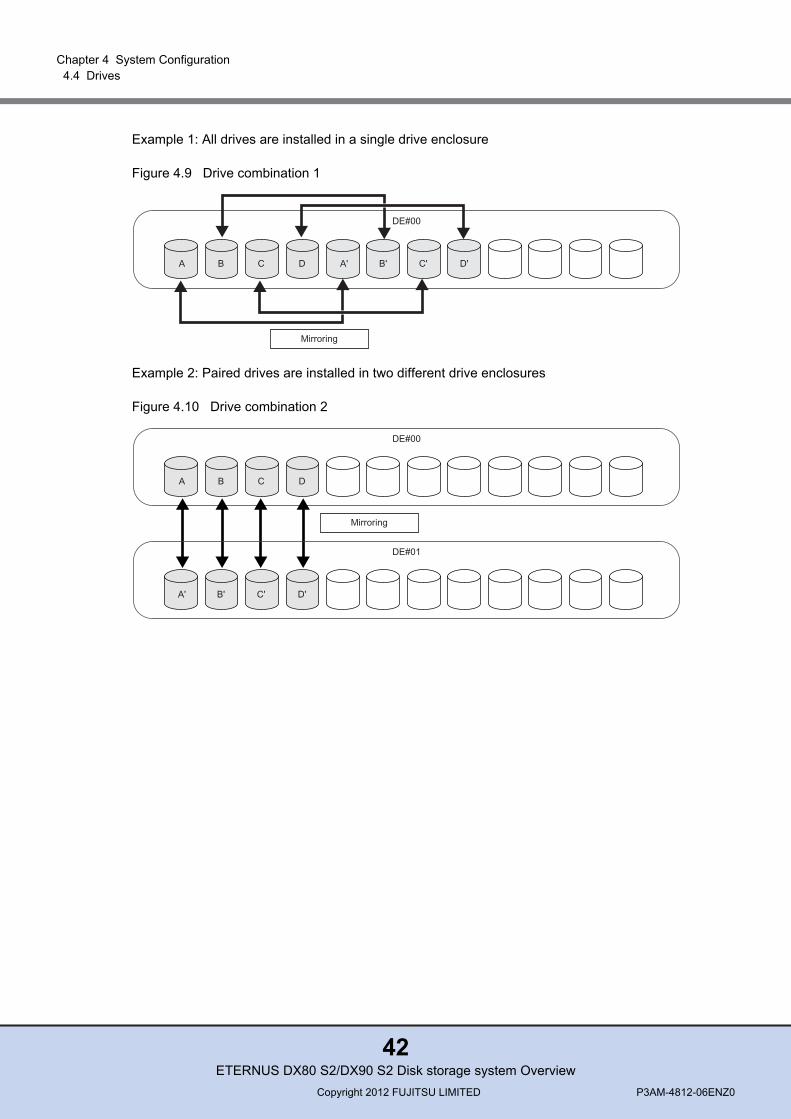
4.4.3 Drive Installation
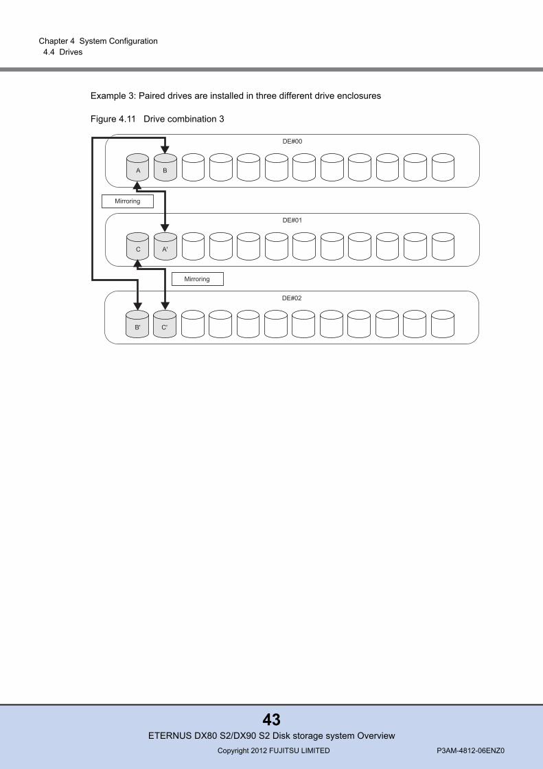
No restrictions on the installation location of drives apply if the same types of drives are used to createRAID groups.To improve reliability, the installation location of drives that configure a RAID group must beconsidered. When a RAID level that performs mirroring (RAID1, RAID1+0) is created, installing drivesthat are configured in pairs to different enclosures improves reliability.
RAID1+0 is used in the following examples to explain the drive combinations for RAID levels thatconfigure mirrored pairs.The drive number is determined by the DE-ID of the drive enclosure and the slot number in which thedrive is installed. Starting from the smallest drive number in the configuration, half of the drives areallocated into one group and the remaining drives are allocated into the other group. Each drive in thedifferent groups are paired for mirroring.
RAID level Formula for user capacity computation
RAID0 Drive capacity × Number of drives
RAID1 Drive capacity × Number of drives ÷ 2
RAID1+0 Drive capacity × Number of drives ÷ 2
RAID5 Drive capacity × (Number of drives - 1)
RAID5+0 Drive capacity × (Number of drives - 2)
RAID6 Drive capacity × (Number of drives - 2)
ETERNUS DX80 S2/DX90 S2 Disk storage system OverviewCopyright 2012 FUJITSU LIMITED P3AM-4812-06ENZ0
41
Chapter 4 System Configuration 4.4 Drives
Example 1: All drives are installed in a single drive enclosure
Figure 4.9 Drive combination 1
Example 2: Paired drives are installed in two different drive enclosures
Figure 4.10 Drive combination 2
DE#00
Mirroring
A B C D A' B' C' D'
DE#00
Mirroring
A B C D
DE#01
A' B' C' D'
ETERNUS DX80 S2/DX90 S2 Disk storage system OverviewCopyright 2012 FUJITSU LIMITED P3AM-4812-06ENZ0
42
Chapter 4 System Configuration 4.4 Drives
Example 3: Paired drives are installed in three different drive enclosures
Figure 4.11 Drive combination 3
DE#02
B' C'
DE#01
Mirroring
C A'
DE#00
Mirroring
A B
ETERNUS DX80 S2/DX90 S2 Disk storage system OverviewCopyright 2012 FUJITSU LIMITED P3AM-4812-06ENZ0
43
Chapter 4 System Configuration 4.5 Hot Spares
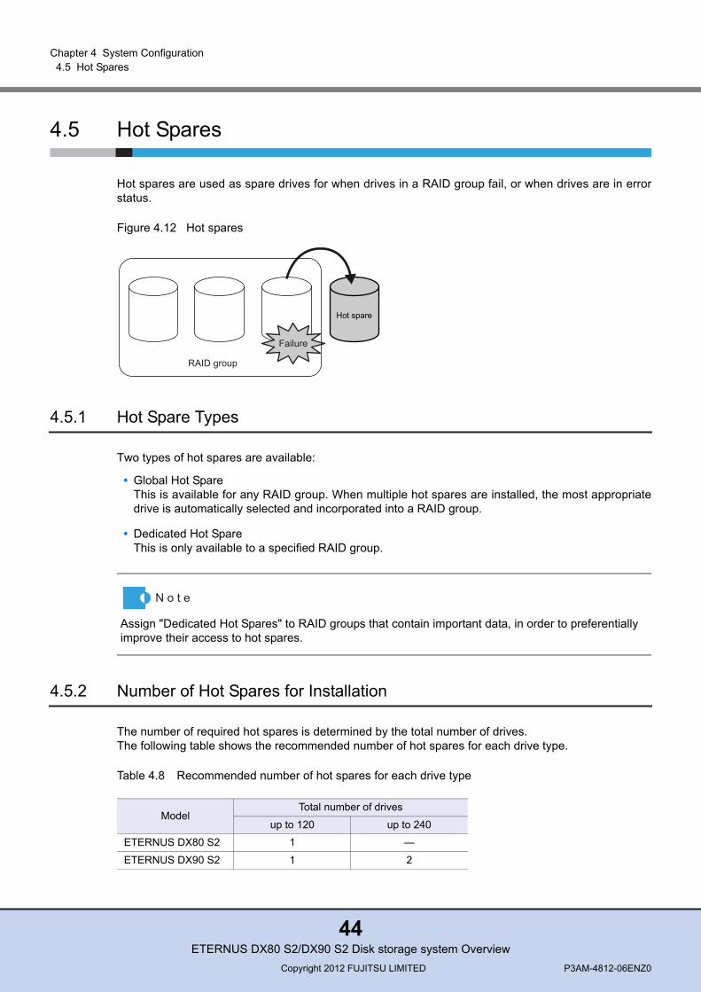
4.5 Hot Spares
Hot spares are used as spare drives for when drives in a RAID group fail, or when drives are in errorstatus.
Figure 4.12 Hot spares
4.5.1 Hot Spare Types
Two types of hot spares are available:
• Global Hot SpareThis is available for any RAID group. When multiple hot spares are installed, the most appropriatedrive is automatically selected and incorporated into a RAID group.
• Dedicated Hot SpareThis is only available to a specified RAID group.
4.5.2 Number of Hot Spares for Installation
The number of required hot spares is determined by the total number of drives. The following table shows the recommended number of hot spares for each drive type.
Table 4.8 Recommended number of hot spares for each drive type
Hot spare
Failure
RAID group
Assign "Dedicated Hot Spares" to RAID groups that contain important data, in order to preferentially improve their access to hot spares.
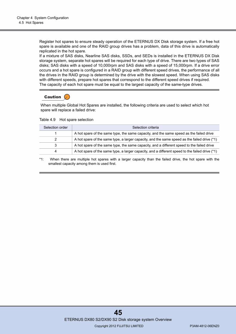
ModelTotal number of drives
up to 120 up to 240
ETERNUS DX80 S2 1 —
ETERNUS DX90 S2 1 2
ETERNUS DX80 S2/DX90 S2 Disk storage system OverviewCopyright 2012 FUJITSU LIMITED P3AM-4812-06ENZ0
44
Chapter 4 System Configuration 4.5 Hot Spares
Register hot spares to ensure steady operation of the ETERNUS DX Disk storage system. If a free hotspare is available and one of the RAID group drives has a problem, data of this drive is automaticallyreplicated in the hot spare. If a mixture of SAS disks, Nearline SAS disks, SSDs, and SEDs is installed in the ETERNUS DX Diskstorage system, separate hot spares will be required for each type of drive. There are two types of SASdisks; SAS disks with a speed of 10,000rpm and SAS disks with a speed of 15,000rpm. If a drive erroroccurs and a hot spare is configured in a RAID group with different speed drives, the performance of allthe drives in the RAID group is determined by the drive with the slowest speed. When using SAS diskswith different speeds, prepare hot spares that correspond to the different speed drives if required. The capacity of each hot spare must be equal to the largest capacity of the same-type drives.
Table 4.9 Hot spare selection
*1: When there are multiple hot spares with a larger capacity than the failed drive, the hot spare with thesmallest capacity among them is used first.
When multiple Global Hot Spares are installed, the following criteria are used to select which hot spare will replace a failed drive:
Selection order Selection criteria
1 A hot spare of the same type, the same capacity, and the same speed as the failed drive
2 A hot spare of the same type, a larger capacity, and the same speed as the failed drive (*1)
3 A hot spare of the same type, the same capacity, and a different speed to the failed drive
4 A hot spare of the same type, a larger capacity, and a different speed to the failed drive (*1)
ETERNUS DX80 S2/DX90 S2 Disk storage system OverviewCopyright 2012 FUJITSU LIMITED P3AM-4812-06ENZ0
45

Chapter 5
Basic FunctionsThis chapter explains the basic functions of ETERNUS DX Disk storage systems.
5.1 Data Protection
The ETERNUS DX Disk storage system has functions to securely protect user data when an erroroccurs.
5.1.1 Data Block Guard
When the ETERNUS DX Disk storage system receives data from the server (when data is written fromthe server), the Data Block Guard function adds eight bytes check codes to each block (every 512bytes) of the user data and verifies the user data at multiple checkpoints to ensure data consistency.This function can detect a data error when data is destroyed or data corruption occurs. When theETERNUS DX Disk storage system sends data to the server (when data is read from the server), thecheck codes are removed after the check, ensuring that data consistency is verified in the wholestorage system.If an error is detected while data is being written, the data is read again from the data that is duplicatedin the cache memory. This data is checked for consistency and then written.If an error is detected while data is being read from a drive, the data is restored using RAIDredundancy.
Figure 5.1 Data block guard function
Cache memory
2
1
2
3
Controller
Write
1 Check Code append
2 Check Code confirmation
3 Check Code confirmation & removal
A0 CC A1 CC A2 CC
A0 A1 A2User data
A0 CC A1 CC A2 CC
A0 A1 A2User data
CC: Check Code
Read
Eight bytes check code isappended to every 512bytes’ user data.
Written data
A0 CC A1 CC A2 CC
ETERNUS DX80 S2/DX90 S2 Disk storage system OverviewCopyright 2012 FUJITSU LIMITED P3AM-4812-06ENZ0
46
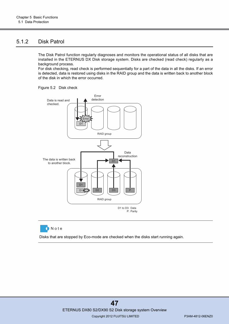
Chapter 5 Basic Functions 5.1 Data Protection
5.1.2 Disk Patrol
The Disk Patrol function regularly diagnoses and monitors the operational status of all disks that areinstalled in the ETERNUS DX Disk storage system. Disks are checked (read check) regularly as abackground process.For disk checking, read check is performed sequentially for a part of the data in all the disks. If an erroris detected, data is restored using disks in the RAID group and the data is written back to another blockof the disk in which the error occurred.
Figure 5.2 Disk check
Disks that are stopped by Eco-mode are checked when the disks start running again.
RAID group
D1
Data is read and checked.
D1
Datareconstruction
D1
D2 D3 P
RAID group
Errordetection
The data is written back to another block.
Error
D1 to D3: P:
DataParity
D1
ETERNUS DX80 S2/DX90 S2 Disk storage system OverviewCopyright 2012 FUJITSU LIMITED P3AM-4812-06ENZ0
47
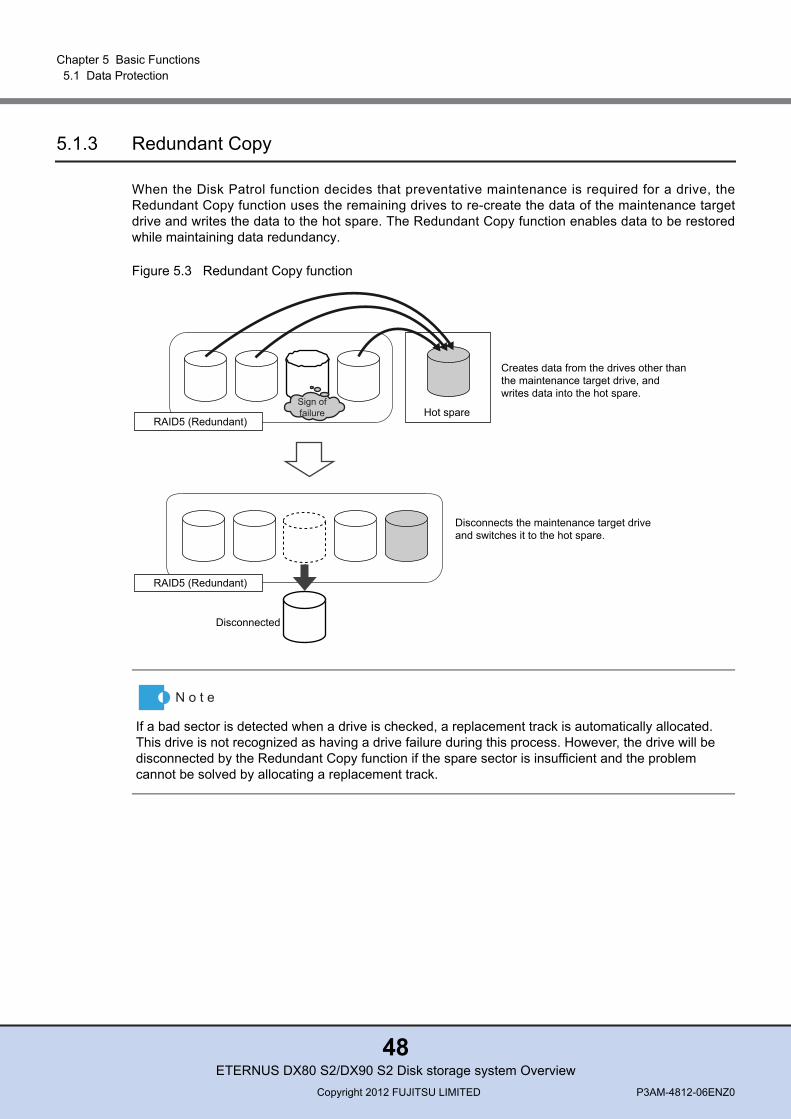
Chapter 5 Basic Functions 5.1 Data Protection
5.1.3 Redundant Copy
When the Disk Patrol function decides that preventative maintenance is required for a drive, theRedundant Copy function uses the remaining drives to re-create the data of the maintenance targetdrive and writes the data to the hot spare. The Redundant Copy function enables data to be restoredwhile maintaining data redundancy.
Figure 5.3 Redundant Copy function
If a bad sector is detected when a drive is checked, a replacement track is automatically allocated. This drive is not recognized as having a drive failure during this process. However, the drive will be disconnected by the Redundant Copy function if the spare sector is insufficient and the problem cannot be solved by allocating a replacement track.
Hot spare
Creates data from the drives other thanthe maintenance target drive, andwrites data into the hot spare.
Disconnects the maintenance target drive and switches it to the hot spare.
Disconnected
RAID5 (Redundant)
Sign offailure
RAID5 (Redundant)
ETERNUS DX80 S2/DX90 S2 Disk storage system OverviewCopyright 2012 FUJITSU LIMITED P3AM-4812-06ENZ0
48

Chapter 5 Basic Functions 5.1 Data Protection
5.1.4 Rebuild/Copyback
When a drive fails and RAID group redundancy is broken, Rebuild/Copyback restores the drive statusback to normal status as a background process. If a free hot spare is available when one of the RAIDgroup drives has a problem, data of this drive is automatically replicated in the hot spare. This ensuresdata redundancy.
Figure 5.4 Rebuild/Copyback function
Hot spare
Hot spare
Creates data from the drives other thanthe failed drive and writes the data intothe hot spare.
After replacing has been completed,copies the data from the hot spareto the new drive.
Replaces the failed drive with the new drive.
Failure
Rebuild
Copyback
RAID5 (Redundant)
RAID5 (No Redundancy)
RAID5 (Redundant)
RAID5 (Redundant)
ETERNUS DX80 S2/DX90 S2 Disk storage system OverviewCopyright 2012 FUJITSU LIMITED P3AM-4812-06ENZ0
49
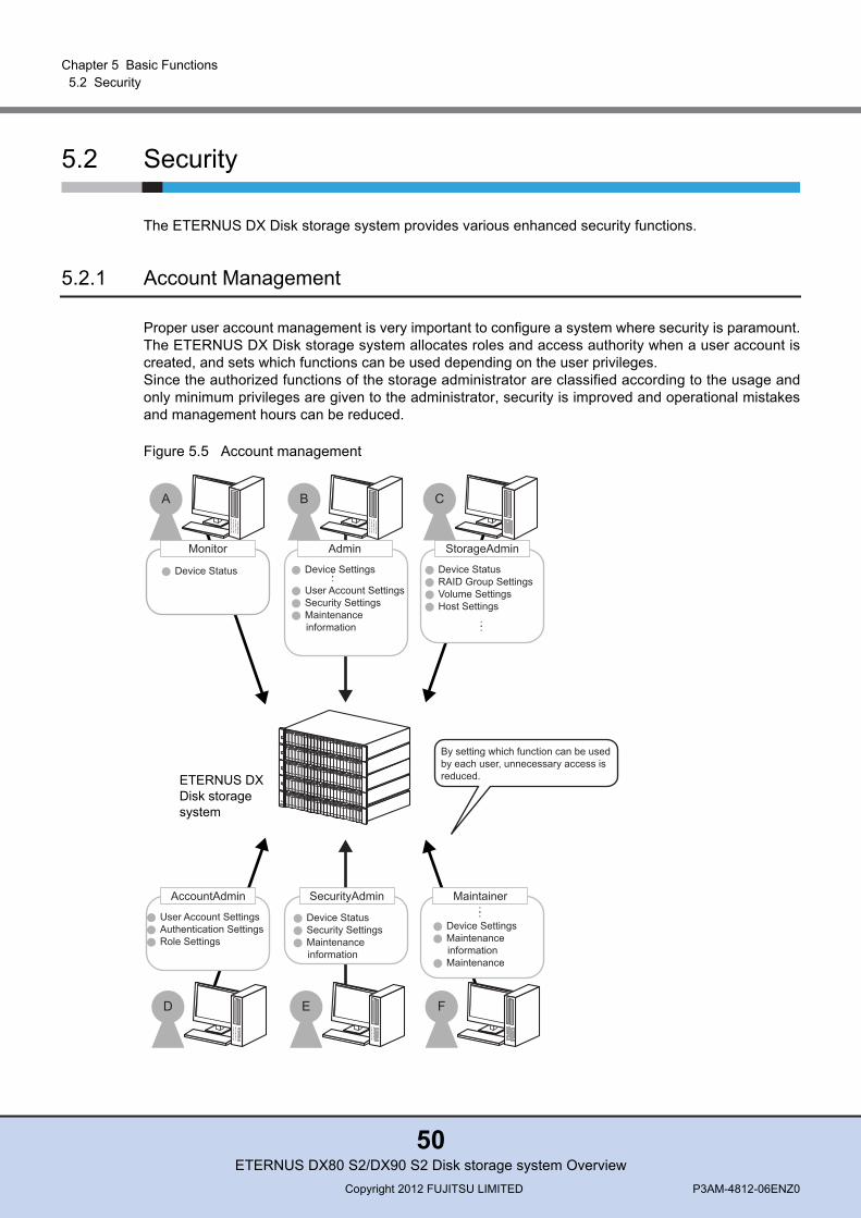
Chapter 5 Basic Functions 5.2 Security
5.2 Security
The ETERNUS DX Disk storage system provides various enhanced security functions.
5.2.1 Account Management
Proper user account management is very important to configure a system where security is paramount.The ETERNUS DX Disk storage system allocates roles and access authority when a user account iscreated, and sets which functions can be used depending on the user privileges.Since the authorized functions of the storage administrator are classified according to the usage andonly minimum privileges are given to the administrator, security is improved and operational mistakesand management hours can be reduced.
Figure 5.5 Account management
Monitor
Device Status
Admin
Device Settings : : User Account Settings Security Settings Maintenance
information
StorageAdmin
Device Status RAID Group Settings Volume Settings Host Settings
Maintainer : :
Device Settings Maintenance
information Maintenance
SecurityAdmin
Device Status Security Settings Maintenance
information
AccountAdmin
User Account Settings Authentication Settings Role Settings
A B C
D E F
By setting which function can be used by each user, unnecessary access is reduced. ETERNUS DX
Disk storage system
::
ETERNUS DX80 S2/DX90 S2 Disk storage system OverviewCopyright 2012 FUJITSU LIMITED P3AM-4812-06ENZ0
50
Chapter 5 Basic Functions 5.2 Security
5.2.2 User Authentication
Internal Authentication and External Authentication are available as logon authentication methods.RADIUS authentication can be used for External Authentication.
■ Internal AuthenticationInternal Authentication is performed using the authentication function of the ETERNUS DX Diskstorage system.The following authentication functions are available when the ETERNUS DX Disk storage system isconnected via a LAN using operation management software.
● User account authentication
User account authentication uses the user account information that is registered in the ETERNUSDX Disk storage system to verify user logins. Up to 64 user accounts can be set.
● SSL authentication
ETERNUS Web GUI supports https connections using SSL/TLS. Since data on the network isencrypted, security can be ensured. Server certifications that are required for connection areobtained by installing authenticated certifications or by being automatically created in the ETERNUSDX Disk storage system.
● SSH authentication
Since ETERNUS CLI supports SSH connections, data on the network can be encrypted and sent/received. The server key for SSH varies depending on the ETERNUS DX Disk storage system.When the server certification is updated, the server key is updated as well.Password authentication and client public key authentication are available as authenticationmethods for SSH connections.The following table shows the supported client public keys.
Table 5.1 Type of client public key
The following iSCSI authentication is available for a host connection and remote copy.
● iSCSI authentication
The Challenge Handshake Authentication Protocol (CHAP) is supported for iSCSI connections. ForCHAP Authentication, unidirectional CHAP or bidirectional CHAP can be selected. Whenunidirectional CHAP is used, the target authenticates the initiator to prevent fraudulent access.When bidirectional CHAP is used, the target authenticates the initiator to prevent fraudulent accessand the initiator authenticates the target to prevent impersonation. CHAP is supported by hostconnections (iSCSI-CA) and REC connections (iSCSI-RA). In addition, Internet Storage NameService (iSNS) is supported as the iSCSI name solution.
Type of public key Complexity (bits)
OpenSSH style RSA for SSH v1 1024, 2048, 4096
IETF style DSA for SSH v2 1024, 2048, 4096
IETF style RSA for SSH v2 1024, 2048, 4096
ETERNUS DX80 S2/DX90 S2 Disk storage system OverviewCopyright 2012 FUJITSU LIMITED P3AM-4812-06ENZ0
51
Chapter 5 Basic Functions 5.2 Security
■ External AuthenticationExternal Authentication uses the user account information (user name, password, and role name) thatis registered on an external authentication server.
● RADIUS authentication
Use of the Remote Authentication Dial-In User Service (RADIUS) protocol enables the consolidationof authentication information for remote access.An authentication request is sent to the RADIUS authentication server that is outside the ETERNUSsystem network. The authentication method can be selected from CHAP and PAP. Two RADIUSauthentication servers can be connected to balance user account information and to create aredundant configuration.The RADIUS server authenticates the user and responds with the ETERNUS DX Disk storagesystem role(s) identified by the Vendor Specific Attribute (VSA).
ETERNUS DX80 S2/DX90 S2 Disk storage system OverviewCopyright 2012 FUJITSU LIMITED P3AM-4812-06ENZ0
52
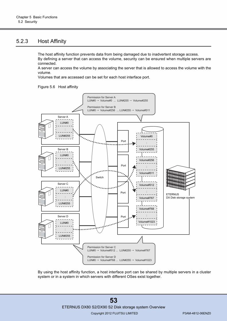
Chapter 5 Basic Functions 5.2 Security
5.2.3 Host Affinity
The host affinity function prevents data from being damaged due to inadvertent storage access. By defining a server that can access the volume, security can be ensured when multiple servers areconnected. A server can access the volume by associating the server that is allowed to access the volume with thevolume.Volumes that are accessed can be set for each host interface port.
Figure 5.6 Host affinity
By using the host affinity function, a host interface port can be shared by multiple servers in a clustersystem or in a system in which servers with different OSes exist together.
Server A
LUN#0
:
LUN#255
Server B
LUN#0
:
LUN#255
Server C
LUN#0
:
LUN#255
Volume#0
:
Volume#255
Volume#256
:
Volume#511
Server D
LUN#0
:
LUN#255
Volume#512
:
Volume#767
Volume#768
Volume#1023
:
Permission for Server ALUN#0 Volume#0 ... LUN#255 Volume#255
Permission for Server BLUN#0 Volume#256 ... LUN#255 Volume#511
Permission for Server CLUN#0 Volume#512 ... LUN#255 Volume#767
Permission for Server DLUN#0 Volume#768 ... LUN#255 Volume#1023
Switch
Port
Port
Port
Port
ETERNUS DX Disk storage system
ETERNUS DX80 S2/DX90 S2 Disk storage system OverviewCopyright 2012 FUJITSU LIMITED P3AM-4812-06ENZ0
53
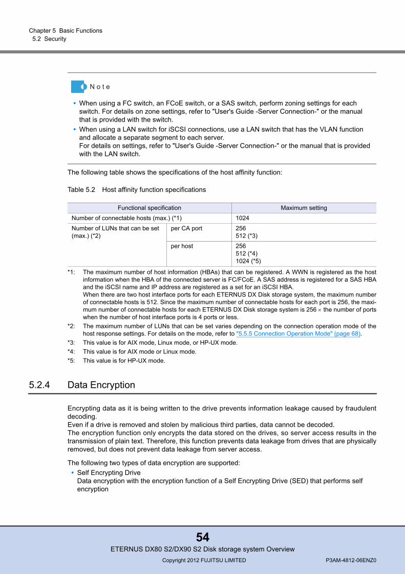
Chapter 5 Basic Functions 5.2 Security
The following table shows the specifications of the host affinity function:
Table 5.2 Host affinity function specifications
*1: The maximum number of host information (HBAs) that can be registered. A WWN is registered as the hostinformation when the HBA of the connected server is FC/FCoE. A SAS address is registered for a SAS HBAand the iSCSI name and IP address are registered as a set for an iSCSI HBA.When there are two host interface ports for each ETERNUS DX Disk storage system, the maximum numberof connectable hosts is 512. Since the maximum number of connectable hosts for each port is 256, the maxi-mum number of connectable hosts for each ETERNUS DX Disk storage system is 256 × the number of portswhen the number of host interface ports is 4 ports or less.
*2: The maximum number of LUNs that can be set varies depending on the connection operation mode of thehost response settings. For details on the mode, refer to "5.5.5 Connection Operation Mode" (page 68).
*3: This value is for AIX mode, Linux mode, or HP-UX mode.*4: This value is for AIX mode or Linux mode.*5: This value is for HP-UX mode.
5.2.4 Data Encryption
Encrypting data as it is being written to the drive prevents information leakage caused by fraudulentdecoding.Even if a drive is removed and stolen by malicious third parties, data cannot be decoded.The encryption function only encrypts the data stored on the drives, so server access results in thetransmission of plain text. Therefore, this function prevents data leakage from drives that are physicallyremoved, but does not prevent data leakage from server access.
The following two types of data encryption are supported: • Self Encrypting Drive
Data encryption with the encryption function of a Self Encrypting Drive (SED) that performs self encryption
• When using a FC switch, an FCoE switch, or a SAS switch, perform zoning settings for each switch. For details on zone settings, refer to "User's Guide -Server Connection-" or the manual that is provided with the switch.
• When using a LAN switch for iSCSI connections, use a LAN switch that has the VLAN function and allocate a separate segment to each server.For details on settings, refer to "User's Guide -Server Connection-" or the manual that is provided with the LAN switch.
Functional specification Maximum setting
Number of connectable hosts (max.) (*1) 1024
Number of LUNs that can be set (max.) (*2)
per CA port 256512 (*3)
per host 256512 (*4)1024 (*5)
ETERNUS DX80 S2/DX90 S2 Disk storage system OverviewCopyright 2012 FUJITSU LIMITED P3AM-4812-06ENZ0
54

Chapter 5 Basic Functions 5.2 Security
• Volume conversion encryptionData encryption with the encryption function of the firmware for the ETERNUS DX Disk storage system on a volume basis
Encryption using SEDs is recommended because SEDs do not affect system performance.
Table 5.3 Data encryption function specifications
*1: AES (Advanced Encryption Standard: Federal Information Processing Standards) method*2: Federal Information Processing Standard (FIPS)
The Fujitsu original encryption method uses a Fujitsu original algorithm that has been specificallycreated for ETERNUS DX Disk storage systems.
The following section describes the features of each encryption function.
■ Self Encrypting DriveEach SED has the encryption function and data can be encrypted by controlling the encryption functionof a SED from the controller. A SED uses an encryption key when encrypting and writing data. Thisencryption key cannot be read from a SED.The controller performs authentication using the authentication key that is saved in the controller andaccesses the drives. An authentication key is automatically created in the ETERNUS DX Disk storagesystem by the setting in ETERNUS Web GUI or ETERNUS CLI. Each ETERNUS DX Disk storagesystem has its own authentication key. Only one type of authentication key can be registered in theETERNUS DX Disk storage system.
■ Volume conversion encryption
This function converts a volume to an encrypted volume in the ETERNUS DX Disk storage system.Encryption is performed when data is written from the cache memory to the drive.When encrypted data is read, the data is decrypted in the cache memory.For Standard/Open volumes, SDVs, and SDPVs, encryption is performed for each volume. For ThinProvisioning Volumes and Flexible Tier Volumes (FTVs), encryption is performed for each pool.The Fujitsu original method has practically the same security level as AES128. The time that is requiredfor conversion is shorter than AES. The Fujitsu original encryption method is recom-mended for useunless a standard encryption method is required.
Functional specification Self Encrypting Drive (SED) Volume conversion encryption
Type of key Authentication key Encryption key
Encryption unit Drive Volume, Pool (RAID group)
Encryption method AES256 AES128 (*1)/Fujitsu original
FIPS authentication (*2) FIPS 140 N/A
ETERNUS DX80 S2/DX90 S2 Disk storage system OverviewCopyright 2012 FUJITSU LIMITED P3AM-4812-06ENZ0
55

Chapter 5 Basic Functions 5.3 Volume Configuration Optimization
Figure 5.7 Data encryption
5.3 Volume Configuration Optimization
This section explains the functions that optimize volume configurations.Drives and drive enclosures can be added during system operation in an ETERNUS DX Disk storagesystem according to changes in the operation load and performance conditions. The ETERNUS DX Disk storage system allows for the expansion of volumes and RAID groupcapacities, migration among RAID groups, and the changing of RAID levels when the volumes aredefined. Exact details depend on the desired operation. Select from the following procedures.
■ Expansion of logical volume capacity
• RAID Migration (with increased migration destination capacity)When volume capacity is insufficient, a volume can be moved to a RAID group that has enough free space. This function is recommended for use when the desired free space is available in the destination.
• LUN ConcatenationAdds areas of free space to an existing volume to expand its capacity. This uses existing free space to efficiently expand the volume.
■ Expansion of RAID group capacity
• Logical Device ExpansionAdds new drives to an existing RAID group to expand the RAID group capacity. This is used to expand the existing RAID group capacity instead of adding a new RAID group to add the volumes.
123 123 123
123 123 123
??? ??? ???
??? ??? ???
ETERNUS DX Diskstorage system
Encrypted
Unencrypted
Setting and management of encryption
Server
Server
Server
???
Prevention of information leakage
? ? ?
ETERNUS DX80 S2/DX90 S2 Disk storage system OverviewCopyright 2012 FUJITSU LIMITED P3AM-4812-06ENZ0
56
Chapter 5 Basic Functions 5.3 Volume Configuration Optimization
■ Migration among RAID groups
• RAID MigrationIf the performance of the current RAID groups is not satisfactory due to conflicting volumes, RAID Migration may be used to improve the performance by redistributing the RAID group configuration.
■ Changing the RAID level
• RAID Migration (to a RAID group with a different RAID level)Migrating to a RAID group with a different RAID level changes the RAID level of volumes. This is used to convert a given volume to a different RAID level.
• Logical Device Expansion (and changing RAID levels when adding the new drives)The RAID level may also be changed when adding new drives to a RAID group. This is used to convert the RAID level of all the volumes belonging to a given RAID group.
■ Striping for multiple RAID groups
• Wide StripingDistributing a single volume to multiple RAID groups makes I/O access from the server more efficient and improves the performance.
For details on the above procedures, refer to "ETERNUS Web GUI User’s Guide" and "ETERNUS CLIUser’s Guide".
ETERNUS DX80 S2/DX90 S2 Disk storage system OverviewCopyright 2012 FUJITSU LIMITED P3AM-4812-06ENZ0
57
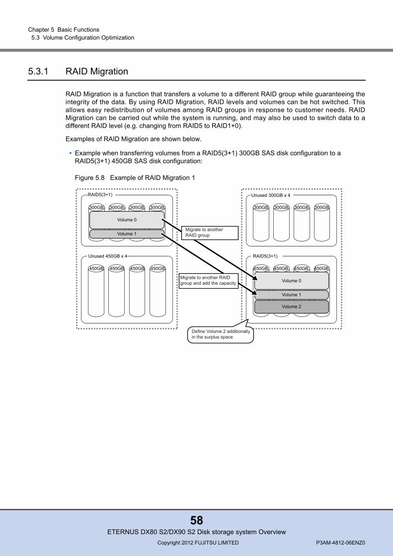
Chapter 5 Basic Functions 5.3 Volume Configuration Optimization
5.3.1 RAID Migration
RAID Migration is a function that transfers a volume to a different RAID group while guaranteeing theintegrity of the data. By using RAID Migration, RAID levels and volumes can be hot switched. Thisallows easy redistribution of volumes among RAID groups in response to customer needs. RAIDMigration can be carried out while the system is running, and may also be used to switch data to adifferent RAID level (e.g. changing from RAID5 to RAID1+0).
Examples of RAID Migration are shown below.
• Example when transferring volumes from a RAID5(3+1) 300GB SAS disk configuration to a RAID5(3+1) 450GB SAS disk configuration:
Figure 5.8 Example of RAID Migration 1
RAID5(3+1)
Unused 450GB x 4 RAID5(3+1)
300GB 300GB 300GB 300GB
450GB 450GB 450GB 450GB 450GB 450GB 450GB 450GB
300GB 300GB 300GB 300GB
Unused 300GB x 4
Volume 2
Volume 1
Volume 0
Volume 1
Define Volume 2 additionallyin the surplus space
Migrate to another RAIDgroup and add the capacity
Migrate to anotherRAID group
Volume 0
ETERNUS DX80 S2/DX90 S2 Disk storage system OverviewCopyright 2012 FUJITSU LIMITED P3AM-4812-06ENZ0
58
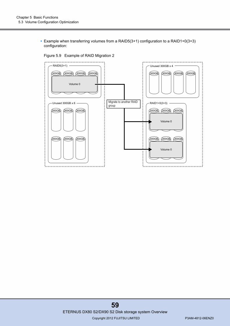
Chapter 5 Basic Functions 5.3 Volume Configuration Optimization
• Example when transferring volumes from a RAID5(3+1) configuration to a RAID1+0(3+3) configuration:
Figure 5.9 Example of RAID Migration 2
300GB 300GB 300GB300GB
300GB 300GB300GB
300GB 300GB300GB
Volume 0
Volume 0
RAID1+0(3+3)
300GB 300GB300GB
300GB 300GB300GB
Unused 300GB x 6
300GB 300GB 300GB300GB
Volume 0
RAID5(3+1)
Migrate to another RAID group
Unused 300GB x 4
ETERNUS DX80 S2/DX90 S2 Disk storage system OverviewCopyright 2012 FUJITSU LIMITED P3AM-4812-06ENZ0
59
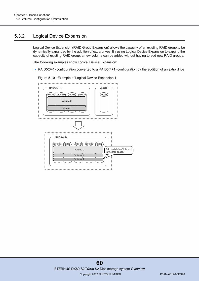
Chapter 5 Basic Functions 5.3 Volume Configuration Optimization
5.3.2 Logical Device Expansion
Logical Device Expansion (RAID Group Expansion) allows the capacity of an existing RAID group to bedynamically expanded by the addition of extra drives. By using Logical Device Expansion to expand thecapacity of existing RAID group, a new volume can be added without having to add new RAID groups.
The following examples show Logical Device Expansion:
• RAID5(3+1) configuration converted to a RAID5(4+1) configuration by the addition of an extra drive
Figure 5.10 Example of Logical Device Expansion 1
300GB
Unused
300GB 300GB 300GB 300GB
Volume 0
Volume 1
RAID5(3+1)
300GB 300GB 300GB 300GB 300GB
Volume 0
Volume 1
Volume 2
RAID5(4+1)
Add and define Volume 2in the free space.
ETERNUS DX80 S2/DX90 S2 Disk storage system OverviewCopyright 2012 FUJITSU LIMITED P3AM-4812-06ENZ0
60
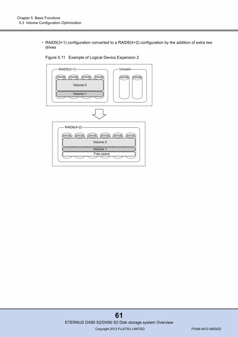
Chapter 5 Basic Functions 5.3 Volume Configuration Optimization
• RAID5(3+1) configuration converted to a RAID6(4+2) configuration by the addition of extra two drives
Figure 5.11 Example of Logical Device Expansion 2
300GB
300GB
Unused
300GB 300GB 300GB 300GB
Volume 0
Volume 1
RAID5(3+1)
300GB 300GB 300GB 300GB 300GB
Volume 0
Volume 1Free space
RAID6(4+2)
300GB
ETERNUS DX80 S2/DX90 S2 Disk storage system OverviewCopyright 2012 FUJITSU LIMITED P3AM-4812-06ENZ0
61

Chapter 5 Basic Functions 5.3 Volume Configuration Optimization
5.3.3 LUN Concatenation
LUN Concatenation is a function that is used to add new area to a volume for expanding the volumecapacity available to the server. This function enables the reuse of free area in a RAID group and canbe used to solve capacity shortages. The maximum capacity of a volume that is expanded by LUNConcatenation is 128TB.The following example shows the concatenation of an unused area of a different RAID group into Vol-ume 2 in order to expand the capacity of Volume 2.
Figure 5.12 Example of LUN Concatenation
LUN Concatenation cannot be performed when the drive type for the RAID group to which the concatenation source volume belongs and the drive type to which the concatenation destination volume belongs do not match.
• When the concatenation source volume is configured with SAS disks or Nearline SAS disks, volumes that are configured with SAS disks or Nearline SAS disks can be concatenated.
• When the concatenation source volume is configured with SSDs, volumes that are configured with SSDs can be concatenated.
• When the concatenation source volume is configured with SEDs, volumes that are configured with SEDs can be concatenated.
300GB 300GB 300GB 300GB
Volume 0
Volume 2
RAID5(3+1)
300GB 300GB 300GB 300GB
Unused area
Volume 1
RAID5(3+1)
300GB 300GB 300GB 300GB
Volume 0
RAID5(3+1)
300GB 300GB 300GB 300GB
Volume 1
RAID5(3+1)
Volume 2
ETERNUS DX80 S2/DX90 S2 Disk storage system OverviewCopyright 2012 FUJITSU LIMITED P3AM-4812-06ENZ0
62
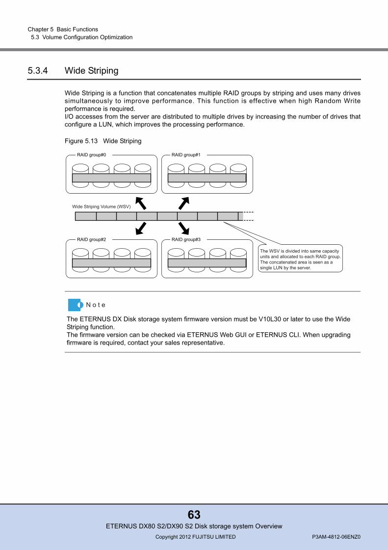
Chapter 5 Basic Functions 5.3 Volume Configuration Optimization
5.3.4 Wide Striping
Wide Striping is a function that concatenates multiple RAID groups by striping and uses many drivessimultaneously to improve performance. This function is effective when high Random Writeperformance is required.I/O accesses from the server are distributed to multiple drives by increasing the number of drives thatconfigure a LUN, which improves the processing performance.
Figure 5.13 Wide Striping
The ETERNUS DX Disk storage system firmware version must be V10L30 or later to use the Wide Striping function. The firmware version can be checked via ETERNUS Web GUI or ETERNUS CLI. When upgrading firmware is required, contact your sales representative.
RAID group#0 RAID group#1
RAID group#2 RAID group#3
Wide Striping Volume (WSV)
The WSV is divided into same capacity units and allocated to each RAID group.The concatenated area is seen as a single LUN by the server.
ETERNUS DX80 S2/DX90 S2 Disk storage system OverviewCopyright 2012 FUJITSU LIMITED P3AM-4812-06ENZ0
63
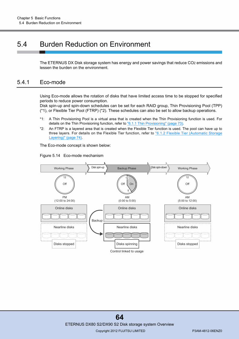
Chapter 5 Basic Functions 5.4 Burden Reduction on Environment
5.4 Burden Reduction on Environment
The ETERNUS DX Disk storage system has energy and power savings that reduce CO2 emissions andlessen the burden on the environment.
5.4.1 Eco-mode
Using Eco-mode allows the rotation of disks that have limited access time to be stopped for specifiedperiods to reduce power consumption.Disk spin-up and spin-down schedules can be set for each RAID group, Thin Provisioning Pool (TPP)(*1), or Flexible Tier Pool (FTRP) (*2). These schedules can also be set to allow backup operations.
*1: A Thin Provisioning Pool is a virtual area that is created when the Thin Provisioning function is used. Fordetails on the Thin Provisioning function, refer to "6.1.1 Thin Provisioning" (page 73).
*2: An FTRP is a layered area that is created when the Flexible Tier function is used. The pool can have up tothree layers. For details on the Flexible Tier function, refer to "6.1.2 Flexible Tier (Automatic StorageLayering)" (page 74).
The Eco-mode concept is shown below:
Figure 5.14 Eco-mode mechanism
Online disks
Nearline disks
Online disks
Nearline disks
Online disks
Nearline disks
Disks spinning Disks stoppedDisks stopped
Control linked to usage
Working Phase Working PhaseDisk spin-up Disk spin-downBackup Phase
Backup
AM(0:00 to 5:00)
5
PM(12:00 to 24:00)
12
Off
12
OffOff
12
On
AM(5:00 to 12:00)
ETERNUS DX80 S2/DX90 S2 Disk storage system OverviewCopyright 2012 FUJITSU LIMITED P3AM-4812-06ENZ0
64
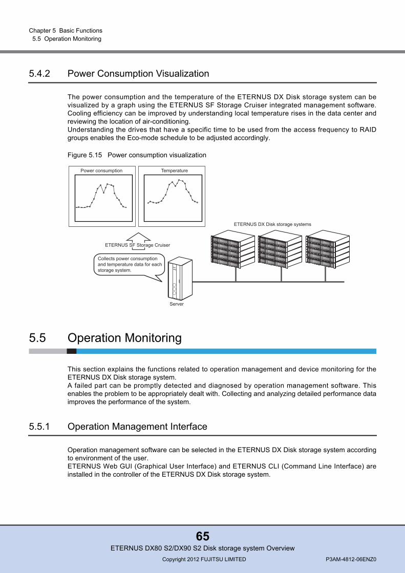
Chapter 5 Basic Functions 5.5 Operation Monitoring
5.4.2 Power Consumption Visualization
The power consumption and the temperature of the ETERNUS DX Disk storage system can bevisualized by a graph using the ETERNUS SF Storage Cruiser integrated management software.Cooling efficiency can be improved by understanding local temperature rises in the data center andreviewing the location of air-conditioning.Understanding the drives that have a specific time to be used from the access frequency to RAIDgroups enables the Eco-mode schedule to be adjusted accordingly.
Figure 5.15 Power consumption visualization
5.5 Operation Monitoring
This section explains the functions related to operation management and device monitoring for theETERNUS DX Disk storage system.A failed part can be promptly detected and diagnosed by operation management software. Thisenables the problem to be appropriately dealt with. Collecting and analyzing detailed performance dataimproves the performance of the system.
5.5.1 Operation Management Interface
Operation management software can be selected in the ETERNUS DX Disk storage system accordingto environment of the user.ETERNUS Web GUI (Graphical User Interface) and ETERNUS CLI (Command Line Interface) areinstalled in the controller of the ETERNUS DX Disk storage system.
Power consumption
Collects power consumption and temperature data for each storage system.
ETERNUS DX Disk storage systems
Server
Temperature
ETERNUS SF Storage Cruiser
ETERNUS DX80 S2/DX90 S2 Disk storage system OverviewCopyright 2012 FUJITSU LIMITED P3AM-4812-06ENZ0
65

Chapter 5 Basic Functions 5.5 Operation Monitoring
■ ETERNUS Web GUIETERNUS Web GUI is a program for settings and operation management that is installed in theETERNUS DX Disk storage system and accessed by using a web browser via http or https.ETERNUS Web GUI has an easy-to-use design that makes intuitive operation possible.The settings that are required for the ETERNUS DX Disk storage system initial installation can beeasily performed by following the wizard and inputting the parameters for the displayed setting items.
■ ETERNUS CLI
ETERNUS CLI supports Telnet or SSH connections. The ETERNUS DX Disk storage system can beset and monitored using commands and command scripts.Most of the functions that can be executed using ETERNUS Web GUI can be executed.
■ ETERNUS SF
"ETERNUS SF" Storage Foundation Software can manage an "ETERNUS series" centered storageenvironment. Since the complicated storage configuration designing and setting operations can beperformed with an easy-to-use GUI, a storage system can be installed easily without needing to havehigh level skills.ETERNUS SF ensures stable operation by managing the entire storage system.
■ SMI-SStorage systems can be managed collectively using the general storage management application thatsupports Version 1.4 of Storage Management Initiative Specification (SMI-S). SMI-S is a storagemanagement interface standard developed and maintained by the Storage Network IndustryAssociation (SNIA). SMI-S can monitor the device status and change configurations such as RAIDgroups, volumes, and Advanced Copy (EC/REC/SnapOPC+).
5.5.2 Event Notification
When an error occurs in the ETERNUS DX Disk storage system, this function notifies the eventinformation to the administrator. The administrator can realize an error occurred without monitoring thescreen all the time.The methods to notify an event are e-mail, SNMP Trap, syslog, remote support, and host sense.The notification methods and levels can be set as required.
• E-mailWhen an event occurs, an e-mail is sent to the specified e-mail address.
• SNMP TrapUsing the SNMP agent function, management information is sent to the SNMP manager (monitoringserver). SNMP v1/v2c/v3 is supported.
• syslogBy registering the syslog destination server in the ETERNUS DX Disk storage system, variousevents that are detected by the ETERNUS DX Disk storage system are sent to the syslog server asevent logs.
ETERNUS DX80 S2/DX90 S2 Disk storage system OverviewCopyright 2012 FUJITSU LIMITED P3AM-4812-06ENZ0
66
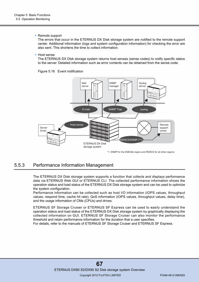
Chapter 5 Basic Functions 5.5 Operation Monitoring
• Remote supportThe errors that occur in the ETERNUS DX Disk storage system are notified to the remote supportcenter. Additional information (logs and system configuration information) for checking the error arealso sent. This shortens the time to collect information.
• Host senseThe ETERNUS DX Disk storage system returns host senses (sense codes) to notify specific statusto the server. Detailed information such as error contents can be obtained from the sense code.
Figure 5.16 Event notification
5.5.3 Performance Information Management
The ETERNUS DX Disk storage system supports a function that collects and displays performancedata via ETERNUS Web GUI or ETERNUS CLI. The collected performance information shows theoperation status and load status of the ETERNUS DX Disk storage system and can be used to optimizethe system configuration.Performance information can be collected such as host I/O information (IOPS values, throughputvalues, respond time, cache hit rate), QoS information (IOPS values, throughput values, delay time),and the usage information of CMs (CPUs) and drives.
ETERNUS SF Storage Cruiser or ETERNUS SF Express can be used to easily understand theoperation status and load status of the ETERNUS DX Disk storage system by graphically displaying thecollected information on GUI. ETERNUS SF Storage Cruiser can also monitor the performancethreshold and retain performance information for the duration that a user specifies. For details, refer to the manuals of ETERNUS SF Storage Cruiser and ETERNUS SF Express.
SNMPmanager
Mailserver
Syslogserver
ETERNUS DX Diskstorage system
Remotesupportcenter
REMCS/SNMP (*1)
Host senseServer(host)
syslogSNMP TrapE-mail
*1: SNMP for the EMEA&I region and REMCS for all other regions
ETERNUS DX80 S2/DX90 S2 Disk storage system OverviewCopyright 2012 FUJITSU LIMITED P3AM-4812-06ENZ0
67
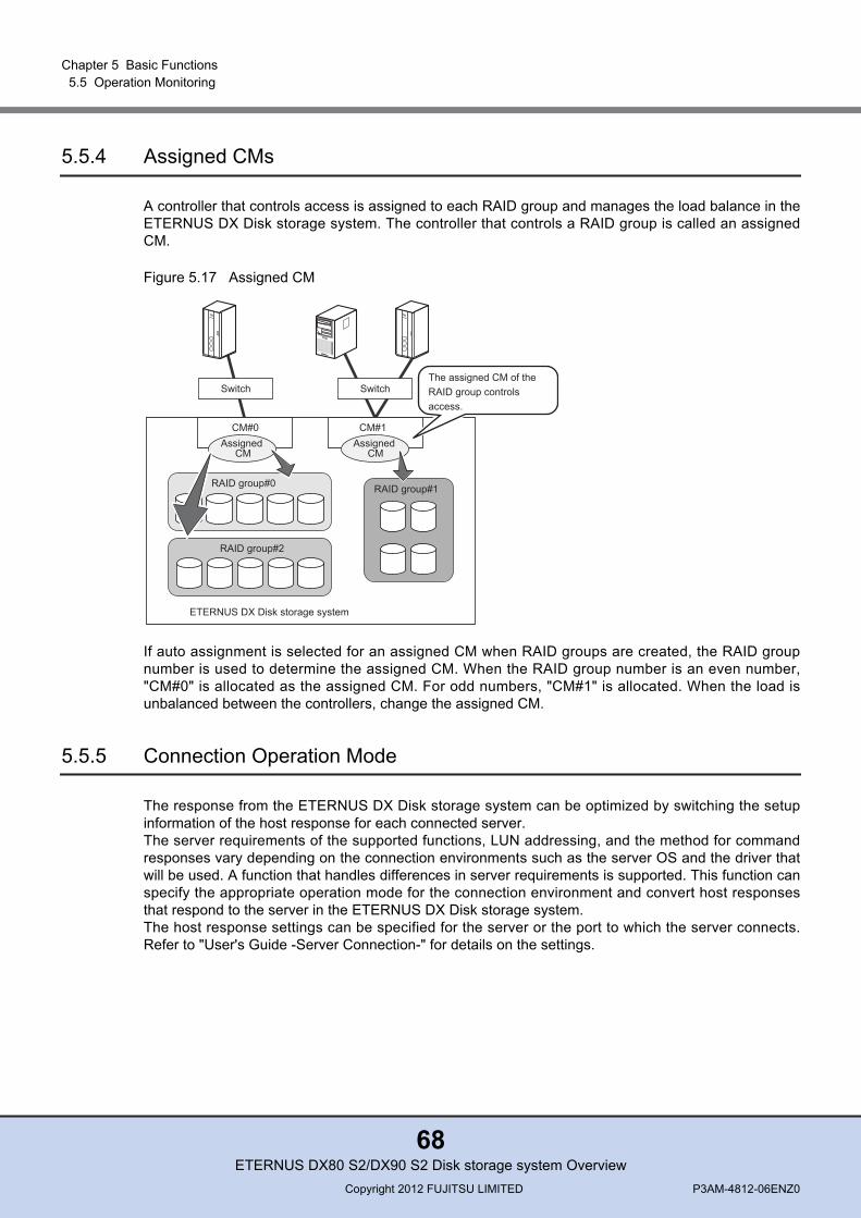
Chapter 5 Basic Functions 5.5 Operation Monitoring
5.5.4 Assigned CMs
A controller that controls access is assigned to each RAID group and manages the load balance in theETERNUS DX Disk storage system. The controller that controls a RAID group is called an assignedCM.
Figure 5.17 Assigned CM
If auto assignment is selected for an assigned CM when RAID groups are created, the RAID groupnumber is used to determine the assigned CM. When the RAID group number is an even number,"CM#0" is allocated as the assigned CM. For odd numbers, "CM#1" is allocated. When the load isunbalanced between the controllers, change the assigned CM.
5.5.5 Connection Operation Mode
The response from the ETERNUS DX Disk storage system can be optimized by switching the setupinformation of the host response for each connected server.The server requirements of the supported functions, LUN addressing, and the method for commandresponses vary depending on the connection environments such as the server OS and the driver thatwill be used. A function that handles differences in server requirements is supported. This function canspecify the appropriate operation mode for the connection environment and convert host responsesthat respond to the server in the ETERNUS DX Disk storage system. The host response settings can be specified for the server or the port to which the server connects.Refer to "User's Guide -Server Connection-" for details on the settings.
ETERNUS DX Disk storage system
Switch
CM#1
RAID group#1RAID group#0
Switch
RAID group#2
CM#0Assigned
CM
The assigned CM of theRAID group controls access.
Assigned CM
ETERNUS DX80 S2/DX90 S2 Disk storage system OverviewCopyright 2012 FUJITSU LIMITED P3AM-4812-06ENZ0
68

Chapter 5 Basic Functions 5.5 Operation Monitoring
Figure 5.18 Host response (connection operation mode)
• If the host response settings are not set correctly, a volume may not be recognized or the desired performance may not be possible. Make sure to select appropriate host response settings.
• The maximum number of volumes (number of LUNs that are set) that can be recognized by the server varies depending on the connection operation mode of the host response settings. The vol-ume settings to allow each server to access the volume can be performed in the host response settings. For details on the function, refer to "5.2.3 Host Affinity" (page 53).
Monitoring time .....
Response status .....
Conversion pattern .....
AIX mode
Convert
Command response
Monitoring time .....
Response status .....
Conversion pattern .....
Command response
Host response settings (for Server A)
Server B Server C
ETERNUS DX Disk storage system
Monitoring time .....
Response status .....
Conversion pattern .....
HP-UX mode
Convert
Command response
Monitoring time .....
Response status .....
Conversion pattern .....
Command response
Host response settings (for Server B)
Monitoring time .....
Response status .....
Conversion pattern .....
AIX mode
Convert
Command response
Monitoring time .....
Response status .....
Conversion pattern .....
Command response
Host response settings (for Server A)
Server A
ETERNUS DX80 S2/DX90 S2 Disk storage system OverviewCopyright 2012 FUJITSU LIMITED P3AM-4812-06ENZ0
69
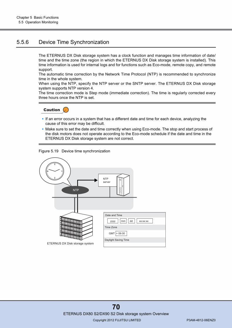
Chapter 5 Basic Functions 5.5 Operation Monitoring
5.5.6 Device Time Synchronization
The ETERNUS DX Disk storage system has a clock function and manages time information of date/time and the time zone (the region in which the ETERNUS DX Disk storage system is installed). Thistime information is used for internal logs and for functions such as Eco-mode, remote copy, and remotesupport.The automatic time correction by the Network Time Protocol (NTP) is recommended to synchronizetime in the whole system.When using the NTP, specify the NTP server or the SNTP server. The ETERNUS DX Disk storagesystem supports NTP version 4.The time correction mode is Step mode (immediate correction). The time is regularly corrected everythree hours once the NTP is set.
Figure 5.19 Device time synchronization
• If an error occurs in a system that has a different date and time for each device, analyzing the cause of this error may be difficult.
• Make sure to set the date and time correctly when using Eco-mode. The stop and start process of the disk motors does not operate according to the Eco-mode schedule if the date and time in the ETERNUS DX Disk storage system are not correct.
NTPserver
ETERNUS DX Disk storage systemDaylight Saving Time
Date and Time
Time Zone
yyyy mm dd xx:xx:xx
GMT + 09.00
NTP
ETERNUS DX80 S2/DX90 S2 Disk storage system OverviewCopyright 2012 FUJITSU LIMITED P3AM-4812-06ENZ0
70
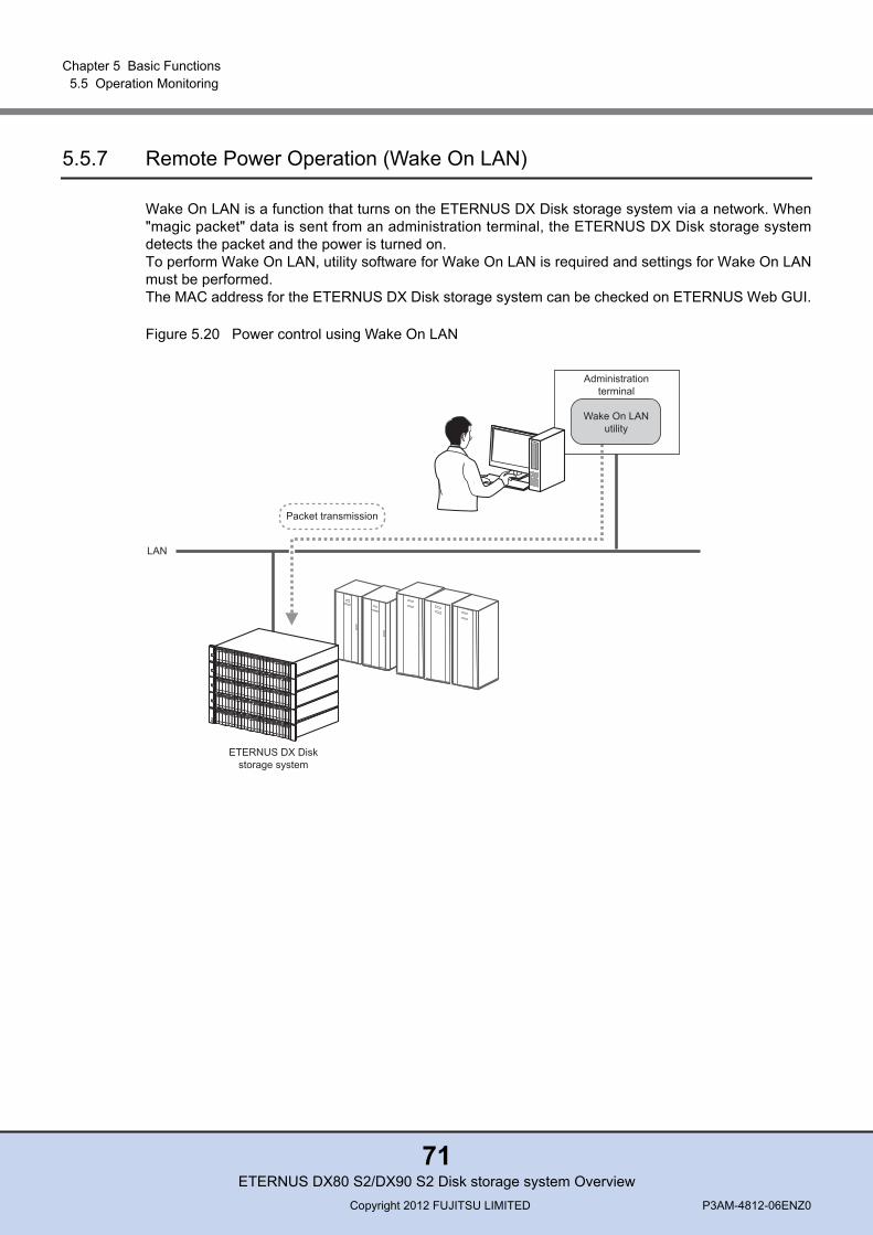
Chapter 5 Basic Functions 5.5 Operation Monitoring
5.5.7 Remote Power Operation (Wake On LAN)
Wake On LAN is a function that turns on the ETERNUS DX Disk storage system via a network. When"magic packet" data is sent from an administration terminal, the ETERNUS DX Disk storage systemdetects the packet and the power is turned on.To perform Wake On LAN, utility software for Wake On LAN is required and settings for Wake On LANmust be performed.The MAC address for the ETERNUS DX Disk storage system can be checked on ETERNUS Web GUI.
Figure 5.20 Power control using Wake On LAN
LAN
Packet transmission
Administrationterminal
Wake On LANutility
ETERNUS DX Diskstorage system
ETERNUS DX80 S2/DX90 S2 Disk storage system OverviewCopyright 2012 FUJITSU LIMITED P3AM-4812-06ENZ0
71
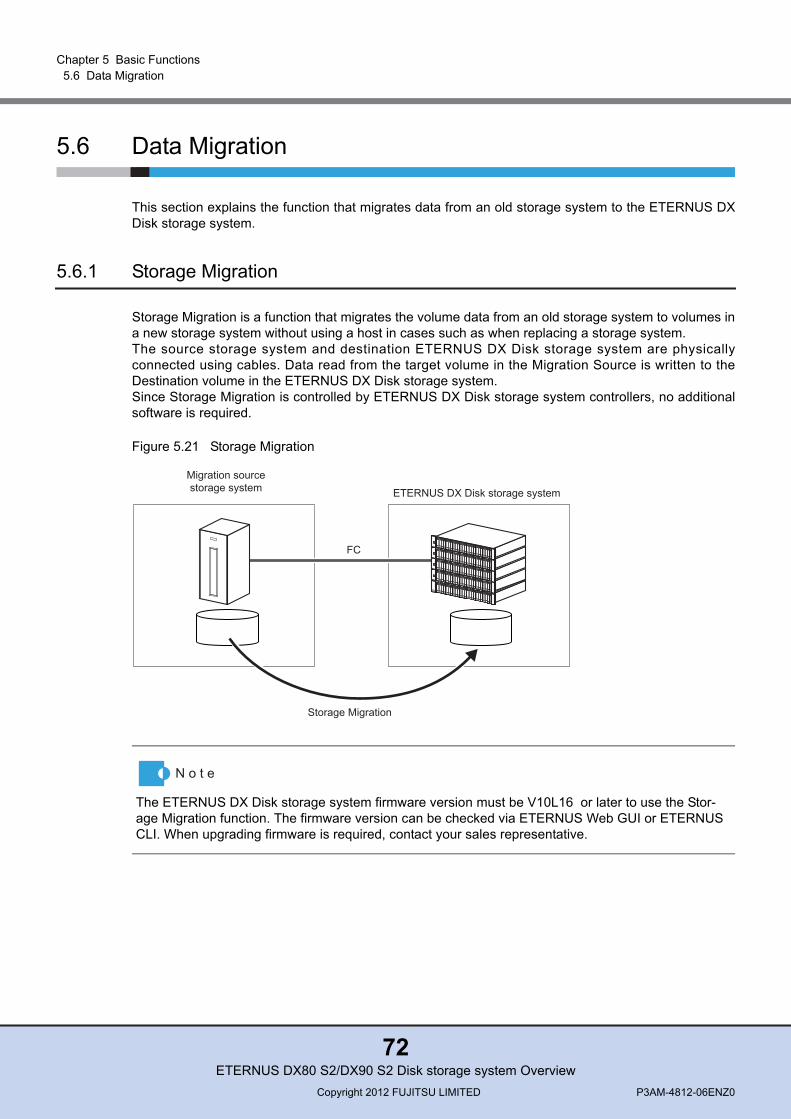
Chapter 5 Basic Functions 5.6 Data Migration
5.6 Data Migration
This section explains the function that migrates data from an old storage system to the ETERNUS DXDisk storage system.
5.6.1 Storage Migration
Storage Migration is a function that migrates the volume data from an old storage system to volumes ina new storage system without using a host in cases such as when replacing a storage system.The source storage system and destination ETERNUS DX Disk storage system are physicallyconnected using cables. Data read from the target volume in the Migration Source is written to theDestination volume in the ETERNUS DX Disk storage system.Since Storage Migration is controlled by ETERNUS DX Disk storage system controllers, no additionalsoftware is required.
Figure 5.21 Storage Migration
The ETERNUS DX Disk storage system firmware version must be V10L16 or later to use the Stor-age Migration function. The firmware version can be checked via ETERNUS Web GUI or ETERNUS CLI. When upgrading firmware is required, contact your sales representative.
ETERNUS DX Disk storage system
Migration sourcestorage system
Storage Migration
FC
ETERNUS DX80 S2/DX90 S2 Disk storage system OverviewCopyright 2012 FUJITSU LIMITED P3AM-4812-06ENZ0
72

Chapter 6
Optional FunctionsThis chapter explains the optional functions of the ETERNUS DX Disk storage system. "Thin Provisioning", "Flexible Tier (automatic storage layering)", and "Advanced Copy" are available asoptional functions. The relevant license must be purchased to use these optional functions.
6.1 Streamlined Operations in the Virtual Environment
The Thin Provisioning function and the Flexible Tier (automatic storage layering) function create virtualdisks to optimize the usability of physical capacity. These functions reduce both the initial investmentand the power consumption requirements since fewer drives have to be installed. A "Thin Provisioning Feature License" is required to use the Thin Provisioning function or the FlexibleTier function.
6.1.1 Thin Provisioning
The Thin Provisioning function virtualizes and allocates storage capacity. This reduces physical storagecapacity and efficiently uses unused capacity.
The user can start ETERNUS DX Disk storage system operation with a small disk capacity, byallocating large virtual disks. Physical disks can be added according to the required capacity withoutaffecting the server.In order to avoid physical disk capacity shortages, thresholds are monitored and physical capacitychange is visualized. This enables the user to know when the storage capacity is insufficient andadditional physical disks can be added to prevent operations being stopped.By using the Thin Provisioning balancing function, the physical allocated capacity of the ThinProvisioning Volume (TPV) can be balanced between RAID groups, and the I/O access to the TPV canbe reallocated to the RAID groups in the pool.
For a single-controller type, the Thin Provisioning function cannot be used.
ETERNUS DX80 S2/DX90 S2 Disk storage system OverviewCopyright 2012 FUJITSU LIMITED P3AM-4812-06ENZ0
73

Chapter 6 Optional Functions 6.1 Streamlined Operations in the Virtual Environment
Figure 6.1 Example of Thin Provisioning
6.1.2 Flexible Tier (Automatic Storage Layering)
The automatic storage layering function automatically redistributes data in the ETERNUS DX Diskstorage system according to access frequency in order to optimize performance and reduce operationcost. Storage layering is performed by moving frequently accessed data to high speed drives such asSSDs and less frequently accessed data to cost effective disks with large capacities. Data can bemoved in blocks that are smaller than the volume capacity.Data is redistributed based on the performance information that is monitored and obtained byETERNUS SF Storage Cruiser. Using Nearline SAS disks can reduce the startup cost of an ETERNUSDX Disk storage system without reducing ETERNUS DX Disk storage system performance.
Although disk usage is based on each volume, freearea in a volume cannot be shared.
Used area
Free area
Vol.1
Vol.1 to Vol.3Used area
Free area
Vol.2 Vol.3
The physical disk can be managed by a pool,and unused capacity is shared with virtualvolumes that belong to the pool.
Conventional way Thin Provisioning
Free area in the physicaldisk is shared with eachvolume.
SAS disks, Nearline SAS disks, SSDs, and SEDs can be used for the Flexible Tier function. Note that the firmware version of the ETERNUS DX Disk storage system must be V10L30 or later to use SEDs with the Flexible Tier function. The firmware version can be checked via ETERNUS Web GUI or ETERNUS CLI. When upgrading firmware is required, contact your sales representative.
ETERNUS DX80 S2/DX90 S2 Disk storage system OverviewCopyright 2012 FUJITSU LIMITED P3AM-4812-06ENZ0
74
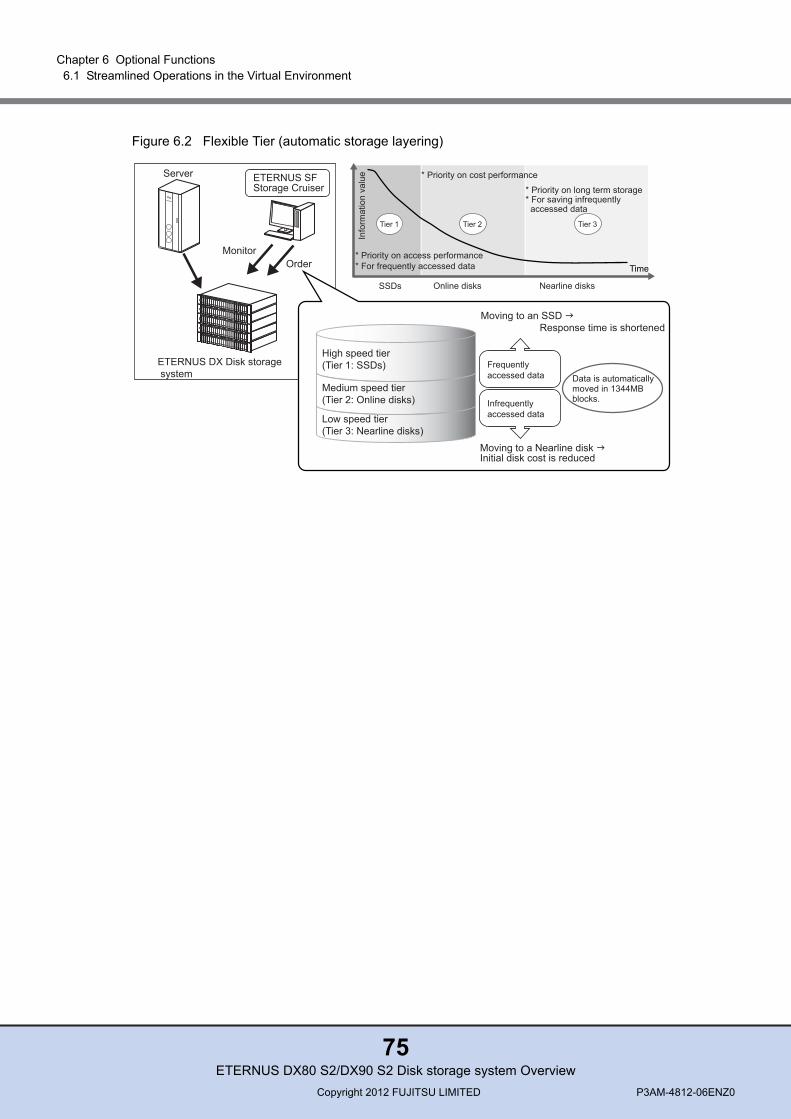
Chapter 6 Optional Functions 6.1 Streamlined Operations in the Virtual Environment
Figure 6.2 Flexible Tier (automatic storage layering)
ETERNUS DX Disk storage system
ETERNUS SF Storage Cruiser
High speed tier(Tier 1: SSDs)
Medium speed tier(Tier 2: Online disks)
Low speed tier(Tier 3: Nearline disks)
Server
Frequently accessed data
Infrequently accessed data
Moving to a Nearline disk Initial disk cost is reduced
Moving to an SSD Response time is shortened
Data is automatically moved in 1344MB blocks.
OrderMonitor
Info
rmat
ion
valu
e
Online disks Nearline disks
Time
SSDs
* Priority on cost performance
* Priority on access performance* For frequently accessed data
* Priority on long term storage* For saving infrequently accessed data
Tier 1 Tier 2 Tier 3
ETERNUS DX80 S2/DX90 S2 Disk storage system OverviewCopyright 2012 FUJITSU LIMITED P3AM-4812-06ENZ0
75

Chapter 6 Optional Functions 6.2 Backup (Advanced Copy)
6.2 Backup (Advanced Copy)
The Advanced Copy function (high-speed copying function) enables data backup (data replication) atany point without stopping the operations of the ETERNUS DX Disk storage system.For the ETERNUS DX Disk storage system backup operation, data can be replicated without takingserver resources. The replication process for large amounts of data can be performed by controlling thetiming and business access so that data protection can be considered separate from operationprocesses.
The following figure shows an example of an Advanced Copy operation using ETERNUS SFAdvancedCopy Manager.
Figure 6.3 Example of Advanced Copy
There are two types of Advanced Copy: a local copy that is performed within a single ETERNUS DXDisk storage system and a remote copy that is performed between ETERNUS DX Disk storagesystems.The methods that are available for the local copy function are "One Point Copy (OPC)", "QuickOPC","SnapOPC", "SnapOPC+", and "Equivalent Copy (EC)". "Remote Equivalent Copy (REC)" is availablefor the remote copy function.
Volume Backup Volume
Tape
Reduction of Backup Time Using Advanced Copy
Time
OperationOperation
Time
OperationOperationBackup Process (System Down Time)
System Down Time
Reduce the system down time by using the high-speed backup with Advanced Copyfunction.
Backup Software
Volume
Tape
Conventional Backup
ETERNUS SF AdvancedCopy Manager
Disk Backup Function Tape Backup Function
ETERNUS DX80 S2/DX90 S2 Disk storage system OverviewCopyright 2012 FUJITSU LIMITED P3AM-4812-06ENZ0
76

Chapter 6 Optional Functions 6.2 Backup (Advanced Copy)
The following table shows the types of controlling software that are used for Advanced Copy functions:
Table 6.1 Controlling software
*1: To use the Advanced Copy functions in a VSS environment, "ETERNUS VSS Hardware Provider" must bedownloaded and installed on the server. For details of "ETERNUS VSS Hardware Provider" and how to installit, refer to the following web-site:
http://www.fujitsu.com/global/services/computing/storage/eternus/tools/vsshp.html
The following table shows the copy functions (copy methods) that are available by registering thelicense:
Table 6.2 List of functions (copy methods)
*1: When an Advanced Copy Feature License is not purchased, up to eight SnapOPC+/QuickOPC sessions canbe used. Try using the Advanced Copy functions to evaluate them before purchase or to plan for their useafter purchase.
Controlling software Features
ETERNUS Web GUI or ETERNUS CLI Copy functions are available without needing any optional software.
Volume Shadow copy Service (VSS) (*1)
VSS can meet various requirements such as data backup in a live data environment, due to its ability to link with ISV backup software or ISV business applications that support the Microsoft Windows Server VSS function.
ETERNUS SF AdvancedCopy Manager(ACM)
ACM supports various OSes and ISV applications. All Advanced Copy functions are available. This also allows data backup in a live data environment via links with Oracle, SQL Server, Exchange Server, and Symfoware Server software.
ETERNUS SF Express ETERNUS SF Express makes it easier to manage the ETERNUS DX Disk storage system and to backup data.
"ETERNUS SF AdvancedCopy Manager", "ETERNUS SF Express", or a VSS environment is required to use the Advanced Copy functions with other operations.
Copy License Model Number of usable
sessions
Controlling software
ETERNUS Web GUI or ETERNUS
CLI
VSS ETERNUS SF Advanced
Copy Manager
ETERNUS SF Express
No license DX80 S2DX90 S2
8 (*1) SnapOPC+ SnapOPC+QuickOPC
– SnapOPC+
License
DX80 S2 1024 SnapOPC+ SnapOPC+QuickOPC
SnapOPC SnapOPC+QuickOPC
OPCEC
SnapOPC SnapOPC+QuickOPC
OPCEC
DX90 S2 2048 SnapOPC+ SnapOPC+QuickOPC
SnapOPC SnapOPC+QuickOPC
OPCEC
REC
SnapOPC SnapOPC+QuickOPC
OPCEC
REC
ETERNUS DX80 S2/DX90 S2 Disk storage system OverviewCopyright 2012 FUJITSU LIMITED P3AM-4812-06ENZ0
77
Chapter 6 Optional Functions 6.2 Backup (Advanced Copy)
Copying is performed for each LUN. Copying can also be performed for each logical disk (such as thepartit ion and volume (the name differs depending on the OS)) when using ETERNUS SFAdvancedCopy Manager.
6.2.1 Local Copy
The Advanced Copy functions offer the following copy methods: "Mirror Suspend", "Background Copy",and "Copy-on-Write". The "Equivalent Copy (EC)" function uses the "Mirror Suspend" method, the "OnePoint Copy (OPC)" function uses the "Background Copy" method, and the "SnapOPC" function usesthe "Copy-on-Write" method.There is also a "QuickOPC" function for the OPC method, which only copies data that has beenupdated since the previous update. The SnapOPC+ function only copies data that is to be updated andperforms generation management of the copy source volume.
● OPC (One Point Copy)
One Point Copy (OPC) is a function that copies data in the volume to another volume in theETERNUS DX Disk storage system at a specific point in time.OPC is suitable for the following usages:
- Performing a backup- Performing system test data replication- Restoring backup data (restoration after replacing a disk when the copy source disk has failed)
● QuickOPC
QuickOPC copies all data as initial copy in the same way as OPC. After the initial copy hascompleted, only updated data (differential data) is copied. QuickOPC is suitable for the followingusages:
- Performing a backup of data that is not updated regularly- Performing system test data replication- Restoration from a backup
• When a volume is copied on a per LUN basis, RAID Migration that expands the migration destination capacity cannot be performed. When RAID Migration is performed for a volume to expand the migration destination capacity, the volume cannot be copied on a per LUN basis.
• For volumes with a copy session, restrictions apply to volume capacity expansion, such as LUN Concatenation and Thin Provisioning volume capacity expansion.For details, refer to "ETERNUS Web GUI User’s Guide".
ETERNUS DX80 S2/DX90 S2 Disk storage system OverviewCopyright 2012 FUJITSU LIMITED P3AM-4812-06ENZ0
78
Chapter 6 Optional Functions 6.2 Backup (Advanced Copy)
● SnapOPC/SnapOPC+ (*1)
As updates occur in the source data, SnapOPC/SnapOPC+ saves the data prior to change to thecopy destination (Snap Data Volume (SDV)). Prepare a Snap Data Pool (SDP) before performingSnapOPC/SnapOPC+. When an amount of data that exceeds the SDV capacity is saved, volumesare supplied from a SDP. SnapOPC/SnapOPC+ is suitable for the following usages:
- Performing temporary backup for tape backup- Performing a backup of data that is not updated regularly (generation management is available
for SnapOPC+)
*1: The difference between SnapOPC and SnapOPC+ is that SnapOPC+ manages the history of updateddata as opposed to SnapOPC. While SnapOPC manages the updated data in units of sessions andsaves the same data redundantly, SnapOPC+ has updated data as history information and canprovide multiple generation-backups.
● EC (Equivalent Copy)
EC makes a mirror copy of the copy source to the copy destination beforehand, and then suspendsthe copy and treats all data as independent data.When copying is resumed, only updated data in the copy source is copied to the copy destination. Ifthe copy destination data has been changed, copy the copy source data again. EC is suitable for thefollowing usages:
- Performing a backup- Performing system test data replication
• Prepare an encrypted SDP when an encrypted SDV is used.• If the SDP capacity is insufficient, a copy cannot be performed. In order to avoid this situation, an
operation that notifies the operation administrator of event information according to the remaining SDP capacity is recommended. For more details on event notification, refer to "5.5.2 Event Notification" (page 66).
ETERNUS DX80 S2/DX90 S2 Disk storage system OverviewCopyright 2012 FUJITSU LIMITED P3AM-4812-06ENZ0
79
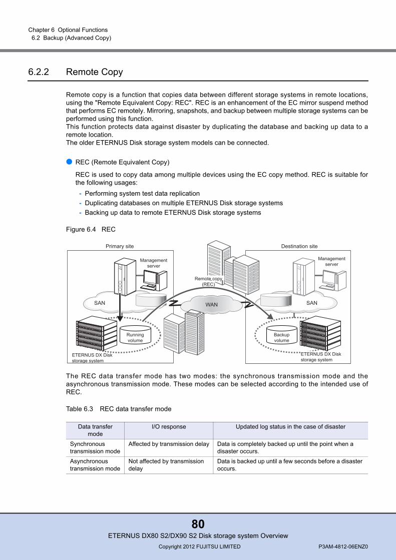
Chapter 6 Optional Functions 6.2 Backup (Advanced Copy)
6.2.2 Remote Copy
Remote copy is a function that copies data between different storage systems in remote locations,using the "Remote Equivalent Copy: REC". REC is an enhancement of the EC mirror suspend methodthat performs EC remotely. Mirroring, snapshots, and backup between multiple storage systems can beperformed using this function.This function protects data against disaster by duplicating the database and backing up data to aremote location.The older ETERNUS Disk storage system models can be connected.
● REC (Remote Equivalent Copy)
REC is used to copy data among multiple devices using the EC copy method. REC is suitable forthe following usages:
- Performing system test data replication- Duplicating databases on multiple ETERNUS Disk storage systems- Backing up data to remote ETERNUS Disk storage systems
Figure 6.4 REC
The REC data transfer mode has two modes: the synchronous transmission mode and theasynchronous transmission mode. These modes can be selected according to the intended use ofREC.
Table 6.3 REC data transfer mode
Data transfer mode
I/O response Updated log status in the case of disaster
Synchronous transmission mode
Affected by transmission delay Data is completely backed up until the point when a disaster occurs.
Asynchronous transmission mode
Not affected by transmission delay
Data is backed up until a few seconds before a disaster occurs.
Destination site
Backupvolume
SAN
Managementserver
Runningvolume
SAN
Managementserver
Primary site
WAN
ETERNUS DX Diskstorage system
ETERNUS DX Diskstorage system
Remote copy(REC)
ETERNUS DX80 S2/DX90 S2 Disk storage system OverviewCopyright 2012 FUJITSU LIMITED P3AM-4812-06ENZ0
80

Chapter 6 Optional Functions 6.2 Backup (Advanced Copy)
■ Synchronous transmission modeData that is updated in a copy source is immediately copied to the copy destination. Write completionsignals to write requests for the server are only returned after both the write to the copy source and thecopy to the copy destination have been done. Synchronizing the data copy with the copy source writeguarantees the contents of the copy source and copy destination at the time of completion.
■ Asynchronous transmission modeData that is updated in a copy source is copied to the copy destination after a completion signal to thewrite request is returned. Therefore, transmission delays in the WAN do not effect REC operation. Asynchronous transmission mode has two sub-modes, the Stack mode and the Consistency mode.Selection of mode will depend on usage pattern. There is also Through mode that is used to finalizedata transfer for the other two modes.
• Stack modeOnly updated block positions are recorded before returning the completion signal to the server, sowaiting-for-response affects on the server are small. Actual transfer of the recorded blocks can beperformed by an independent transfer process.This mode can be used even when the available line bandwidth is small. Therefore, this mode ismainly used for remote backup.
• Consistency modeThis mode guarantees the sequential transmission of updates to the remote copy destination devicein the same order as the writes occurred. Even if a problem occurs with the data transfer order dueto a transmission delay in the WAN, the update order in the copy destination is maintained.This is useful when mirroring databases and copies of multiple connected areas.This mode uses part of the cache memory as a buffer (REC buffer). A Copy via the REC bufferstores multiple REC session I/Os in the REC buffer for a certain period of time. Data for these I/Os iscopied in blocks.When a capacity shortage for the REC buffer occurs, the REC disk buffer can also be used. A RECdisk buffer is used as a temporary destination to save copy data.
• Through modeAfter an I/O response is returned, this mode copies updated data as an extension of the process.This mode is not used for normal transfers. When STOPping or SUSPENDing the Stack mode or theConsistency mode, this mode is used to change the transfer mode to transfer all data that has notbeen transferred or to resume transfers.
ETERNUS DX80 S2/DX90 S2 Disk storage system OverviewCopyright 2012 FUJITSU LIMITED P3AM-4812-06ENZ0
81
Chapter 6 Optional Functions 6.2 Backup (Advanced Copy)
• When REC is performed over a WAN, a bandwidth of at least 50Mbit/s is required if data is not compressed on the line. When data is compressed, a 50Mbit/s or less bandwidth is sufficient.
• When REC is performed over a WAN, the round-trip time of data transmission must be 50ms or less for the synchronous transmission mode and 100ms or less for the asynchronous transmission mode. A setup in which the round-trip time is 10ms or less is recommended for the synchronous transmission mode.
• When a concurrent firmware update is performed, copy sessions must be suspended.• When the REC Consistency mode is used between different storage system models, an equal or
larger number of controllers than the copy source storage system is recommended for the copy destination storage system.
• When the number of controllers in the copy source storage system is eight (*1) and the number of controllers in the copy destination storage system is two or less, the REC Consistency mode cannot be used.
• The ETERNUS DX90 S2, the ETERNUS DX410 S2/DX440 S2, the ETERNUS DX410/DX440, the ETERNUS DX8100 S2/DX8700 S2, and the ETERNUS DX8100/DX8400/DX8700 support REC disk buffers.
• When an older ETERNUS Disk storage system is used as the copy destination, REC cannot be performed between encrypted volumes and unencrypted volumes.*1: The maximum number of controllers that can be installed in the ETERNUS DX8700/DX8700 S2 and
the ETERNUS8000 models 2100 and 2200
ETERNUS DX80 S2/DX90 S2 Disk storage system OverviewCopyright 2012 FUJITSU LIMITED P3AM-4812-06ENZ0
82

Chapter 6 Optional Functions 6.2 Backup (Advanced Copy)
6.2.3 Available Advanced Copy Combinations
Different Advanced Copy types can be combined and used together.
● Restore OPC
For OPC, QuickOPC, SnapOPC, and SnapOPC+, restoration of the copy source from the copydestination is complete immediately upon request.
Figure 6.5 Restore OPC
● EC or REC Reverse
Restoration of the copy source from the copy destination is possible by switching the EC or RECcopy source and destination.
Figure 6.6 EC or REC Reverse
Copy source Copy destination
OPC, QuickOPC,SnapOPC, or SnapOPC+
Restoration from the copy destination to the copy source (Restore OPC)
Copy source Copy destination
EC or REC
EC or REC
Copy destination Copy source
Reverse
ETERNUS DX80 S2/DX90 S2 Disk storage system OverviewCopyright 2012 FUJITSU LIMITED P3AM-4812-06ENZ0
83

Chapter 6 Optional Functions 6.2 Backup (Advanced Copy)
● Multiple copy
Multiple copy destinations can be set for a single copy source area to obtain multiple backups. Up toeight OPC, QuickOPC, SnapOPC, EC, or REC sessions can be set for a multiple copy.
Figure 6.7 Multiple copy
Up to 256 SnapOPC+ copy session generations can be set for a single copy source area whenseven or less multiple copy sessions are already set.
Figure 6.8 Multiple copy (including SnapOPC+)
Copy destination 1
Copy source
Copy destination 2
Copy destination 3
Copy destination 4 Copy destination 5
Copy destination 6
Copy destination 7
Copy destination 8
ETERNUS DX Disk storage systemETERNUS DX Disk storage system
ETERNUS DX Disk storage system
ETERNUS DX Disk storage system
Copy destination 1
Copy destination 2
Copy destination 3
Copy destination 4
Copy destination 5
Copy destination 6
Copy destination 7
ETERNUS DX Disk storage system
ETERNUS DX Disk storage system
Copy source
Copy destination (from one to 256 SnapOPC+ generations)
ETERNUS DX80 S2/DX90 S2 Disk storage system OverviewCopyright 2012 FUJITSU LIMITED P3AM-4812-06ENZ0
84
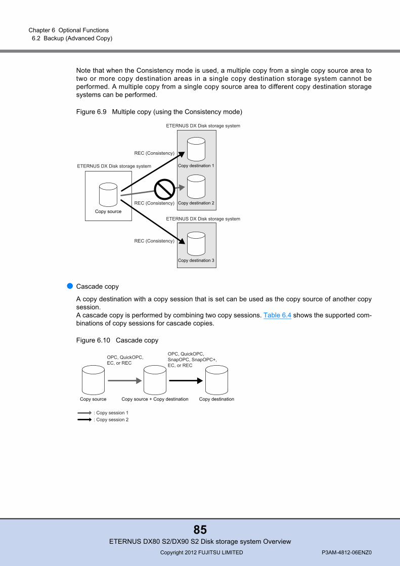
Chapter 6 Optional Functions 6.2 Backup (Advanced Copy)
Note that when the Consistency mode is used, a multiple copy from a single copy source area totwo or more copy destination areas in a single copy destination storage system cannot beperformed. A multiple copy from a single copy source area to different copy destination storagesystems can be performed.
Figure 6.9 Multiple copy (using the Consistency mode)
● Cascade copy
A copy destination with a copy session that is set can be used as the copy source of another copysession.A cascade copy is performed by combining two copy sessions. Table 6.4 shows the supported com-binations of copy sessions for cascade copies.
Figure 6.10 Cascade copy
Copy source
Copy destination 1
Copy destination 2
Copy destination 3
ETERNUS DX Disk storage system
ETERNUS DX Disk storage system
ETERNUS DX Disk storage system
REC (Consistency)
REC (Consistency)
REC (Consistency)
Copy source Copy source + Copy destination Copy destination
OPC, QuickOPC, EC, or REC
OPC, QuickOPC,SnapOPC, SnapOPC+,EC, or REC
: Copy session 1: Copy session 2
ETERNUS DX80 S2/DX90 S2 Disk storage system OverviewCopyright 2012 FUJITSU LIMITED P3AM-4812-06ENZ0
85
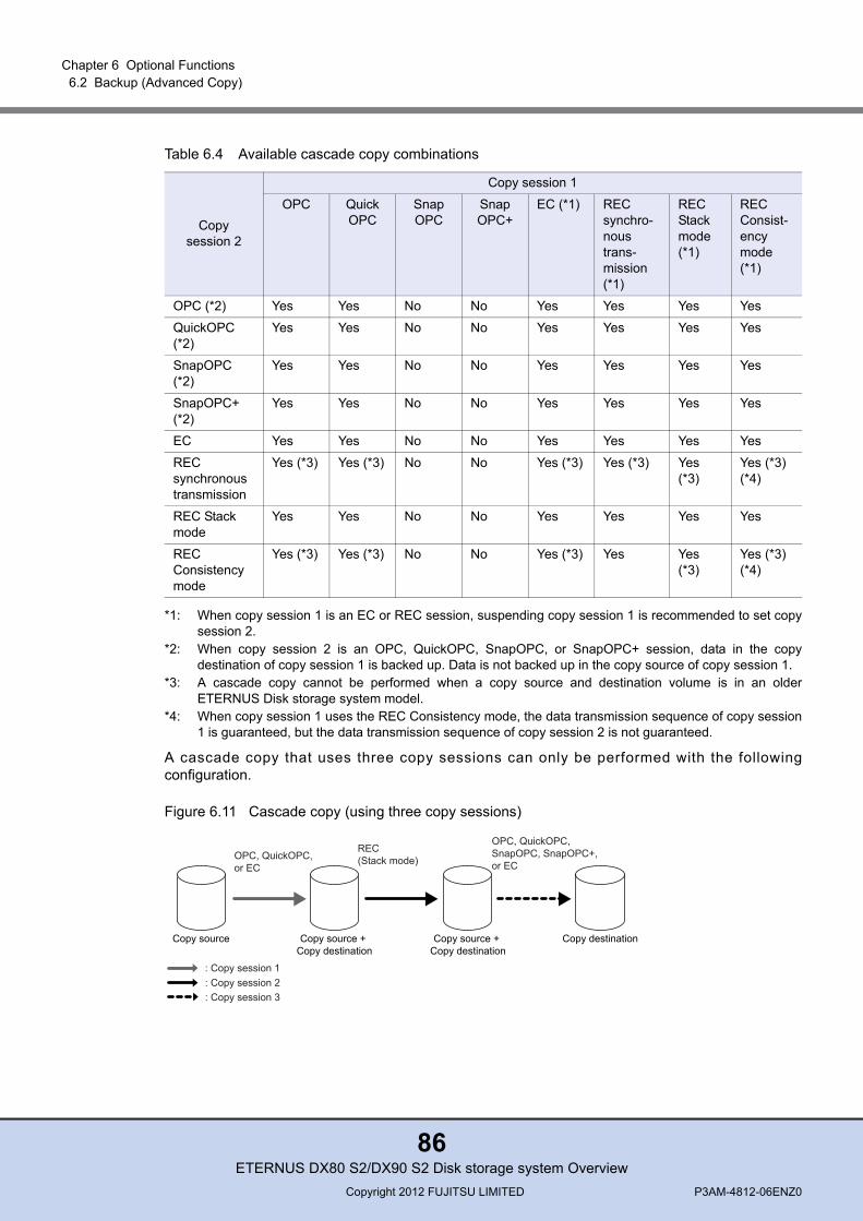
Chapter 6 Optional Functions 6.2 Backup (Advanced Copy)
Table 6.4 Available cascade copy combinations
*1: When copy session 1 is an EC or REC session, suspending copy session 1 is recommended to set copysession 2.
*2: When copy session 2 is an OPC, QuickOPC, SnapOPC, or SnapOPC+ session, data in the copydestination of copy session 1 is backed up. Data is not backed up in the copy source of copy session 1.
*3: A cascade copy cannot be performed when a copy source and destination volume is in an olderETERNUS Disk storage system model.
*4: When copy session 1 uses the REC Consistency mode, the data transmission sequence of copy session1 is guaranteed, but the data transmission sequence of copy session 2 is not guaranteed.
A cascade copy that uses three copy sessions can only be performed with the followingconfiguration.
Figure 6.11 Cascade copy (using three copy sessions)
Copy session 2
Copy session 1
OPC QuickOPC
SnapOPC
SnapOPC+
EC (*1) REC synchro-nous trans-mission (*1)
REC Stack mode (*1)
REC Consist-ency mode (*1)
OPC (*2) Yes Yes No No Yes Yes Yes Yes
QuickOPC (*2)
Yes Yes No No Yes Yes Yes Yes
SnapOPC (*2)
Yes Yes No No Yes Yes Yes Yes
SnapOPC+ (*2)
Yes Yes No No Yes Yes Yes Yes
EC Yes Yes No No Yes Yes Yes Yes
REC synchronous transmission
Yes (*3) Yes (*3) No No Yes (*3) Yes (*3) Yes (*3)
Yes (*3) (*4)
REC Stack mode
Yes Yes No No Yes Yes Yes Yes
REC Consistency mode
Yes (*3) Yes (*3) No No Yes (*3) Yes Yes (*3)
Yes (*3) (*4)
Copy source Copy source + Copy destination
Copy source + Copy destination
OPC, QuickOPC, or EC
REC(Stack mode)
OPC, QuickOPC, SnapOPC, SnapOPC+,or EC
Copy destination
: Copy session 1 : Copy session 2 : Copy session 3
ETERNUS DX80 S2/DX90 S2 Disk storage system OverviewCopyright 2012 FUJITSU LIMITED P3AM-4812-06ENZ0
86

ETERNUS DX80 S2/DX90 S2 Disk storage system Overview
P3AM-4812-06ENZ0
Date of issuance: August 2012Issuance responsibility: FUJITSU LIMITED
• The content of this manual is subject to change without notice.• This manual was prepared with the utmost attention to detail.
However, Fujitsu shall assume no responsibility for any operational problems as the result of errors, omissions, or the use of information in this manual.
• Fujitsu assumes no liability for damages to third party copyrights or other rights arising from the use of any information in this manual.
• The content of this manual may not be reproduced or distributed in part or in its entirety without prior permission from Fujitsu.


![Cisco DX80 Data Sheet - evideo.com.auevideo.com.au/app/uploads/2014/07/dx80.pdf · A high-quality audio system for speakerphone ... (standard-definition [SD] card speed Class 4 or](https://static.documents.pub/doc/80x56/6011ff724a6b8b5d6d2b6a9d/cisco-dx80-data-sheet-a-high-quality-audio-system-for-speakerphone-standard-definition.jpg)


