Published: October 19, 2011 r2011 American Chemical Society 4977 dx.doi.org/10.1021/ef201127y | Energy Fuels 2011, 25, 4977–4985 ARTICLE pubs.acs.org/EF Ethanol Blends and Engine Operating Strategy Effects on Light-Duty Spark-Ignition Engine Particle Emissions James P. Szybist,* ,† Adam D. Youngquist, † Teresa L. Barone, † John M. Storey, † Wayne R. Moore, ‡ Matthew Foster, ‡ and Keith Confer ‡ † Fuels, Engines, and Emissions Research Center, Oak Ridge National Laboratory, NTRC Building, 2360 Cherahala Boulevard, Knoxville, Tennessee 37932, United States ‡ Advanced Powertrain, Delphi Automotive Systems, 3000 University Drive, Auburn Hills, Michigan 48326, United States ABSTRACT: Spark-ignition (SI) engines with direct-injection (DI) fueling can improve fuel economy and vehicle power beyond that of port fuel injection (PFI). Despite this distinct advantage, DI fueling often increases particle number emissions, such that SI exhaust may be subject to future particle emissions regulations. In this study, ethanol blends and engine operating strategy are evaluated for their effectiveness in reducing particle emissions in DI engines. The investigated fuels include a baseline emissions certification gasoline, a blend of 20 vol % ethanol with gasoline (E20), and a blend of 85 vol % ethanol with gasoline (E85). The operating strategies investigated reflect the versatility of emerging cam-based variable valve actuation technology capable of unthrottled operation with either early or late intake valve closing (EIVC or LIVC). Particle emissions are characterized in this study by the particle number size distribution as measured with a scanning mobility particle sizer (SMPS) and by the filter smoke number (FSN). Particle emissions for PFI fueling are very low and comparable for all fuels and breathing conditions. When DI fueling is used for gasoline and E20, the particle number emissions are increased by 1 2 orders of magnitude compared to PFI fueling, depending upon the fuel injection timing. In contrast, when DI fueling is used with E85, the particle number emissions remain low and comparable to PFI fueling. Thus, by using E85, the efficiency and power advantages of DI fueling can be gained without generating the increase in particle emissions observed with gasoline and E20. ’ INTRODUCTION The Energy Independence and Security Act of 2007 (EISA) requires a fuel economy improvement from the 2007 current corporate average fuel economy (CAFE) of 24.1 miles per gallon (mpg) to a CAFE of 35 mpg in the year 2020. 1 In response to a presidential memorandum, the United States Environmental Protection Agency (U.S. EPA) and the National Highway Traffic Safety Administration (NHTSA) have accelerated the timeline by requiring a combined car and light truck fleet average CO 2 emissions of 250 g/mile by 2016, 2 which is approximately equivalent to a combined fleet fuel economy 35.5 mpg. With these regulations as the impetus, technologies designed to improve fuel economy have begun to be incorporated into production vehicles. These technologies include hybrid electric technology, cylinder deactivation, variable valve actuation, and gasoline direct-injection (DI) fueling. DI fueling for gasoline engines is an enabling technology for the development of vehicles with better fuel economy. In combination with turbocharging, gasoline DI fueling significantly improves engine power, which allows the engine displacement volume to be reduced for a given application (downsizing), even while the engine performance improves. 3 When the engine is downsized, the engine friction is reduced and the engine operates at higher engine loads for a larger fraction of the operating map, as quantified by the brake mean effective pressure (BMEP), which results in more efficient operation. In addition, gasoline DI fueling reduces the tendency of a fuel to knock because of enhanced charge cooling, allowing the compression ratio to be increased for higher efficiency. As a result, fuel economy can be increased for vehicles with DI fueling compared to engines with port fuel injection (PFI) technology. DI gasoline engines are being rapidly incorporated into new vehicles in the United States. PFI technology has been nearly ubiquitous in light-duty vehicles over the past 2 decades, accounting for over 99% of all light-duty vehicles sold in the United States each year between 1996 and 2007. 4 Since that time, gasoline DI fueling has begun to emerge, accounting for 2.3% of light-duty gasoline vehicles in 2008 and rising to 8.5% in 2010. 4 The percentage of vehicles with gasoline DI technology in the United States is expected to continue increasing rapidly, with a projection of 60% of all new vehicles by 2016. 5 While gasoline DI technology is beneficial for fuel economy, it produces an increase in particulate matter emissions in comparison to PFI engines. Aakko and Nylund 6 reported that the particle mass emissions for a gasoline DI vehicle were an order of magnitude higher than for a PFI vehicle for the European 70/220/EEC drive cycle. Similarly, the particle number emissions reported by Aikawa et al. 7 were roughly a factor of 5 higher for the DI vehicle than for the PFI vehicle, although direct comparison of these is difficult because different vehicle drive cycles were used. A report issued by the California Air Quality Board 5 estimates that, on average, particle mass emissions are increased somewhere between 2 and 20 times for gasoline DI engines compared to PFI. Received: July 29, 2011 Revised: October 18, 2011
Transcript
Published: October 19, 2011
r 2011 American Chemical Society 4977 dx.doi.org/10.1021/ef201127y | Energy Fuels 2011, 25, 4977–4985
ARTICLE
pubs.acs.org/EF
Ethanol Blends and Engine Operating Strategy Effects on Light-DutySpark-Ignition Engine Particle EmissionsJames P. Szybist,*,† Adam D. Youngquist,† Teresa L. Barone,† John M. Storey,† Wayne R. Moore,‡
Matthew Foster,‡ and Keith Confer‡
†Fuels, Engines, and Emissions Research Center, Oak Ridge National Laboratory, NTRC Building, 2360 Cherahala Boulevard,Knoxville, Tennessee 37932, United States‡Advanced Powertrain, Delphi Automotive Systems, 3000 University Drive, Auburn Hills, Michigan 48326, United States
ABSTRACT: Spark-ignition (SI) engines with direct-injection (DI) fueling can improve fuel economy and vehicle power beyondthat of port fuel injection (PFI). Despite this distinct advantage, DI fueling often increases particle number emissions, such that SIexhaust may be subject to future particle emissions regulations. In this study, ethanol blends and engine operating strategy areevaluated for their effectiveness in reducing particle emissions in DI engines. The investigated fuels include a baseline emissionscertification gasoline, a blend of 20 vol % ethanol with gasoline (E20), and a blend of 85 vol % ethanol with gasoline (E85). Theoperating strategies investigated reflect the versatility of emerging cam-based variable valve actuation technology capable ofunthrottled operation with either early or late intake valve closing (EIVC or LIVC). Particle emissions are characterized in this studyby the particle number size distribution as measured with a scanning mobility particle sizer (SMPS) and by the filter smoke number(FSN). Particle emissions for PFI fueling are very low and comparable for all fuels and breathing conditions.WhenDI fueling is usedfor gasoline and E20, the particle number emissions are increased by 1�2 orders of magnitude compared to PFI fueling, dependingupon the fuel injection timing. In contrast, when DI fueling is used with E85, the particle number emissions remain low andcomparable to PFI fueling. Thus, by using E85, the efficiency and power advantages of DI fueling can be gained without generatingthe increase in particle emissions observed with gasoline and E20.
’ INTRODUCTION
The Energy Independence and Security Act of 2007 (EISA)requires a fuel economy improvement from the 2007 currentcorporate average fuel economy (CAFE) of 24.1 miles per gallon(mpg) to a CAFE of 35 mpg in the year 2020.1 In response to apresidential memorandum, the United States EnvironmentalProtection Agency (U.S. EPA) and the National Highway TrafficSafety Administration (NHTSA) have accelerated the timelineby requiring a combined car and light truck fleet average CO2
emissions of 250 g/mile by 2016,2 which is approximatelyequivalent to a combined fleet fuel economy 35.5 mpg. Withthese regulations as the impetus, technologies designed toimprove fuel economy have begun to be incorporated intoproduction vehicles. These technologies include hybrid electrictechnology, cylinder deactivation, variable valve actuation, andgasoline direct-injection (DI) fueling.
DI fueling for gasoline engines is an enabling technology forthe development of vehicles with better fuel economy. Incombination with turbocharging, gasoline DI fueling significantlyimproves engine power, which allows the engine displacementvolume to be reduced for a given application (downsizing), evenwhile the engine performance improves.3 When the engine isdownsized, the engine friction is reduced and the engine operatesat higher engine loads for a larger fraction of the operating map,as quantified by the brake mean effective pressure (BMEP),which results in more efficient operation. In addition, gasoline DIfueling reduces the tendency of a fuel to knock because ofenhanced charge cooling, allowing the compression ratio to beincreased for higher efficiency. As a result, fuel economy can be
increased for vehicles with DI fueling compared to engines withport fuel injection (PFI) technology.
DI gasoline engines are being rapidly incorporated into newvehicles in the United States. PFI technology has been nearlyubiquitous in light-duty vehicles over the past 2 decades,accounting for over 99% of all light-duty vehicles sold in theUnited States each year between 1996 and 2007.4 Since that time,gasoline DI fueling has begun to emerge, accounting for 2.3% oflight-duty gasoline vehicles in 2008 and rising to 8.5% in 2010.4
The percentage of vehicles with gasoline DI technology in theUnited States is expected to continue increasing rapidly, with aprojection of 60% of all new vehicles by 2016.5
While gasoline DI technology is beneficial for fuel economy, itproduces an increase in particulate matter emissions in comparisonto PFI engines. Aakko and Nylund6 reported that the particle massemissions for a gasoline DI vehicle were an order of magnitudehigher than for a PFI vehicle for the European 70/220/EEC drivecycle. Similarly, the particle number emissions reported by Aikawaet al.7 were roughly a factor of 5 higher for the DI vehicle than forthe PFI vehicle, although direct comparison of these is difficultbecause different vehicle drive cycles were used. A report issued bytheCalifornia AirQuality Board5 estimates that, on average, particlemass emissions are increased somewhere between 2 and 20 timesfor gasoline DI engines compared to PFI.
Reductions in particle emissions from DI engines are beingpursued with a number of different strategies. Moore et al.8 showthat increased charge motion achieved through deactivation ofone of the intake valves is effective in reducing soot emissions, asquantified by the filter smoke number (FSN). Hedge et al.9 showthat exhaust gas recirculation (EGR) is effective at reducingparticle emissions at part-load operation while simultaneouslyimproving fuel consumption, likely through a reduction in throt-tling losses. Additionally, Iyer and Yi10 showed that improvementscan be made in the targeting of the fuel spray to reduce sootemissions. With DI fueling strategies being relatively new toproduction engines, further improvements to fuel injection hard-ware and engine operating strategies may allow for further reduc-tions in particle emissions.
However, solving the issue of increased particle emissionsfrom gasoline DI engines may be complicated by the fact that thefuel diversity in the marketplace is increasing. The same EISAlegislation that requires improved fuel economy also requiresthat the amount of bio-derived fuels increase more than 7-foldfrom their 2007 levels by 2020.1 Although there will be a varietyof different fuel types that contribute, ethanol is expected tocomprise the overwhelming majority of the bio-derived fuel.
A number of investigations have examined the effect of ethanolcontent on particle emissions in vehicles. Storey et al.11 foundthat blends of 10 and 20% ethanol in gasoline (E10 and E20)decreased particle number emissions during vehicle drive cycles,with the 20% blend decreasing particles by about 40% during thehigh-load US06 vehicle drive cycle. In comparison to gasoline,He et al.12 found a 20% reduction in particle emissions with E20but no change with E10. Khalek and Bougher13 showed that E10increased particle emissions compared to two different gasolineformulations, both with higher volatility than the E10. This workshowed the importance of the hydrocarbon fraction of the E10blend and suggests that the heavier hydrocarbons used to controlvapor pressure of E10 may also increase particulate emissions.Aakko and Nylund6 found that the particle mass emissions from85% ethanol (E85) were comparable to those with gasoline in aPFI vehicle but that DI fueling with gasoline produced particleemissions that were an order of magnitude higher.
The previous studies investigating the effect of ethanol fuelson particle emissions have operated production engines in theiroriginal equipment manufacturer (OEM) configurations andcalibrations. There have also been a number of additional recentresearch efforts to optimize engine efficiency for high concentra-tions of ethanol to reduce the fuel economy penalty associatedwith the lower energy density of ethanol.14�18 In addition to theuse of DI fueling, each of these research efforts represents
departures from how spark-ignition (SI) engines are convention-ally operated, particularly in regard to engine breathing strategiesand compression ratio. The purpose of this investigation isto elucidate the effects of fuel type, fueling strategy, and enginebreathing strategy on particle emissions in a flexible SI enginethat was designed for optimization with ethanol.
’EXPERIMENTAL METHODOLOGIES
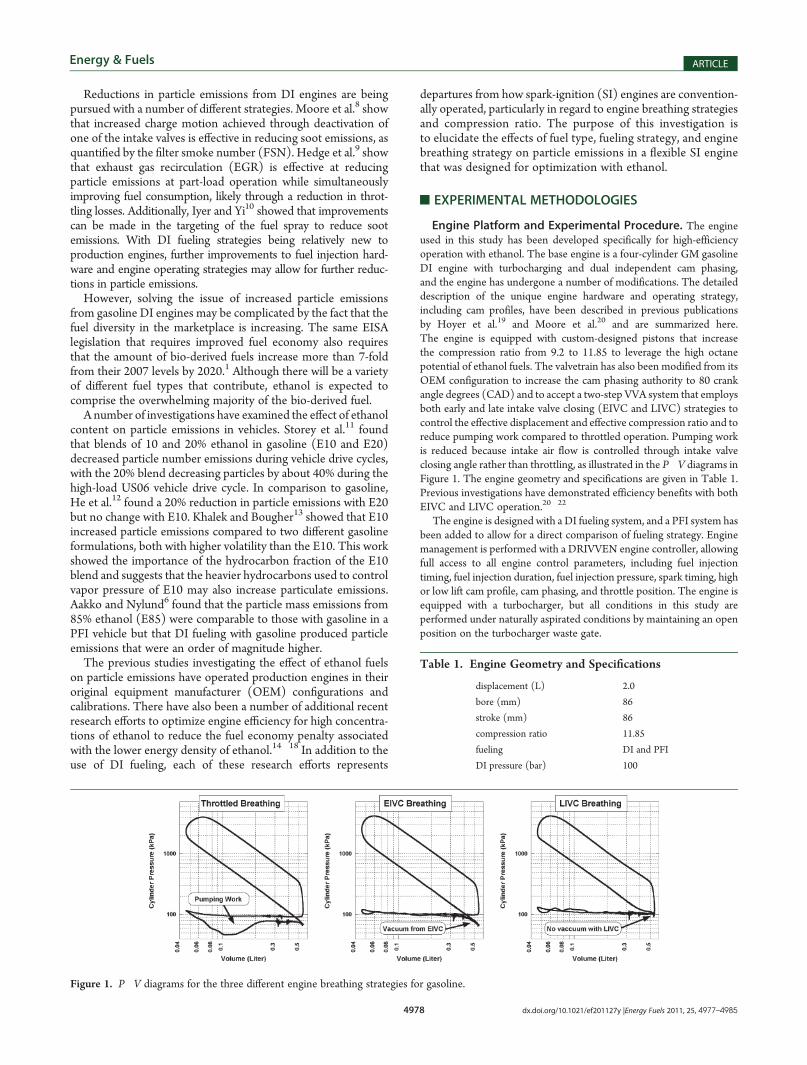
Engine Platform and Experimental Procedure. The engineused in this study has been developed specifically for high-efficiencyoperation with ethanol. The base engine is a four-cylinder GM gasolineDI engine with turbocharging and dual independent cam phasing,and the engine has undergone a number of modifications. The detaileddescription of the unique engine hardware and operating strategy,including cam profiles, have been described in previous publicationsby Hoyer et al.19 and Moore et al.20 and are summarized here.The engine is equipped with custom-designed pistons that increasethe compression ratio from 9.2 to 11.85 to leverage the high octanepotential of ethanol fuels. The valvetrain has also been modified from itsOEM configuration to increase the cam phasing authority to 80 crankangle degrees (CAD) and to accept a two-step VVA system that employsboth early and late intake valve closing (EIVC and LIVC) strategies tocontrol the effective displacement and effective compression ratio and toreduce pumping work compared to throttled operation. Pumping workis reduced because intake air flow is controlled through intake valveclosing angle rather than throttling, as illustrated in the P�V diagrams inFigure 1. The engine geometry and specifications are given in Table 1.Previous investigations have demonstrated efficiency benefits with bothEIVC and LIVC operation.20�22
The engine is designed with a DI fueling system, and a PFI system hasbeen added to allow for a direct comparison of fueling strategy. Enginemanagement is performed with a DRIVVEN engine controller, allowingfull access to all engine control parameters, including fuel injectiontiming, fuel injection duration, fuel injection pressure, spark timing, highor low lift cam profile, cam phasing, and throttle position. The engine isequipped with a turbocharger, but all conditions in this study areperformed under naturally aspirated conditions by maintaining an openposition on the turbocharger waste gate.
Table 1. Engine Geometry and Specifications
displacement (L) 2.0
bore (mm) 86
stroke (mm) 86
compression ratio 11.85
fueling DI and PFI
DI pressure (bar) 100
Figure 1. P�V diagrams for the three different engine breathing strategies for gasoline.
Cylinder pressure and fuel injection command signals are acquired atthe shaft encoder resolution of 0.2 CAD. The cylinder pressure isrecorded from each of the four cylinders using piezoelectric pressuretransducers side-mounted in the engine block. The signals are acquiredusing National Instruments data acquisition hardware and analyzedusing the DRIVVEN combustion analysis toolkit (microDCAT).
Gaseous engine emissions are measured using a standard emissionsbench. NOx and hydrocarbon (HC) emissions are measured directlyfrom the hot exhaust using a chemiluminescence analyzer and a flameionization detector (FID), respectively. Exhaust gas is chilled to con-dense water in the exhaust prior to measurements of CO and CO2 usinginfrared analyzers and for oxygen using a paramagnetic analyzer.
Particulate emissions from the engine are measured using an AVLFSN instrument as well as a scanning mobility particle sizer (SMPS).FSN is an industry standard that has long been used to provide rapid andrepeatable measurements of smoke emissions for diesel engine researchand development. The measurement principle is based on a change infilter paper reflectivity and is intended to be proportional to particulatemass collected on the paper.23 The sensitivity of the FSN instrument islimited at the lowest particle emission levels with both PFI and DIfueling, but it has proven to be a useful measure at many engineconditions for previous gasoline engine studies with DI fueling in thepast.8,24 FSN ismeasured from the raw exhaust downstream of the three-way catalyst.
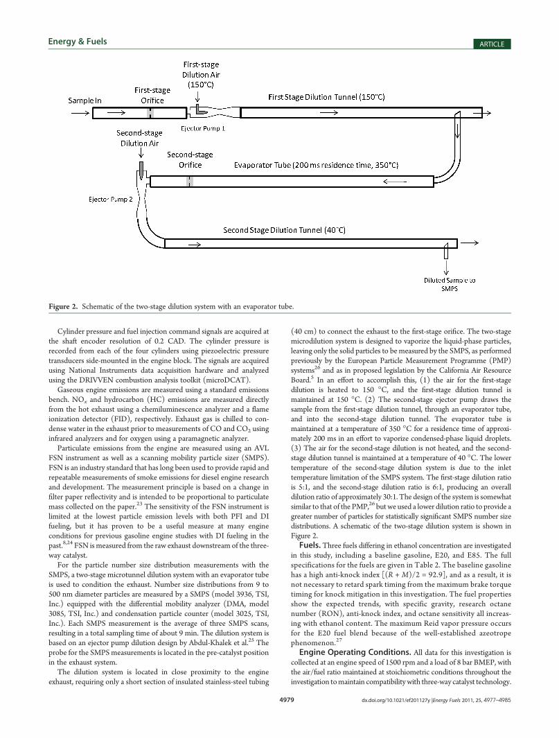
For the particle number size distribution measurements with theSMPS, a two-stage microtunnel dilution system with an evaporator tubeis used to condition the exhaust. Number size distributions from 9 to500 nm diameter particles are measured by a SMPS (model 3936, TSI,Inc.) equipped with the differential mobility analyzer (DMA, model3085, TSI, Inc.) and condensation particle counter (model 3025, TSI,Inc.). Each SMPS measurement is the average of three SMPS scans,resulting in a total sampling time of about 9 min. The dilution system isbased on an ejector pump dilution design by Abdul-Khalek et al.25 Theprobe for the SMPSmeasurements is located in the pre-catalyst positionin the exhaust system.
The dilution system is located in close proximity to the engineexhaust, requiring only a short section of insulated stainless-steel tubing
(40 cm) to connect the exhaust to the first-stage orifice. The two-stagemicrodilution system is designed to vaporize the liquid-phase particles,leaving only the solid particles to bemeasured by the SMPS, as performedpreviously by the European Particle Measurement Programme (PMP)systems26 and as in proposed legislation by the California Air ResourceBoard.5 In an effort to accomplish this, (1) the air for the first-stagedilution is heated to 150 �C, and the first-stage dilution tunnel ismaintained at 150 �C. (2) The second-stage ejector pump draws thesample from the first-stage dilution tunnel, through an evaporator tube,and into the second-stage dilution tunnel. The evaporator tube ismaintained at a temperature of 350 �C for a residence time of approxi-mately 200 ms in an effort to vaporize condensed-phase liquid droplets.(3) The air for the second-stage dilution is not heated, and the second-stage dilution tunnel is maintained at a temperature of 40 �C. The lowertemperature of the second-stage dilution system is due to the inlettemperature limitation of the SMPS system. The first-stage dilution ratiois 5:1, and the second-stage dilution ratio is 6:1, producing an overalldilution ratio of approximately 30:1. The design of the system is somewhatsimilar to that of the PMP,26 but we used a lower dilution ratio to provide agreater number of particles for statistically significant SMPS number sizedistributions. A schematic of the two-stage dilution system is shown inFigure 2.Fuels. Three fuels differing in ethanol concentration are investigated
in this study, including a baseline gasoline, E20, and E85. The fullspecifications for the fuels are given in Table 2. The baseline gasolinehas a high anti-knock index [(R + M)/2 = 92.9], and as a result, it isnot necessary to retard spark timing from the maximum brake torquetiming for knock mitigation in this investigation. The fuel propertiesshow the expected trends, with specific gravity, research octanenumber (RON), anti-knock index, and octane sensitivity all increas-ing with ethanol content. The maximum Reid vapor pressure occursfor the E20 fuel blend because of the well-established azeotropephenomenon.27
Engine Operating Conditions. All data for this investigation iscollected at an engine speed of 1500 rpm and a load of 8 bar BMEP, withthe air/fuel ratio maintained at stoichiometric conditions throughout theinvestigation tomaintain compatibility with three-way catalyst technology.
Figure 2. Schematic of the two-stage dilution system with an evaporator tube.
In the past, it has been particularly challenging to achieve low particleemission levels at this engine condition.8 For each of the three fuels, theengine is operated at the desired engine speed and load using three enginebreathing conditions: conventional throttled operation, unthrottled withEIVC, and unthrottled with LIVC. For each fuel and breathing condition,the engine is operated with three different fueling strategies: singleinjection DI (sDI), multiple injection DI (mDI), and PFI. For the sDIand mDI fueling strategies, a start of injection timing sweep is performed,whereas only a single point is performed for the PFI strategy.
Gaseous emissions, FSN, and engine performance metrics arerecorded at each engine operating point. Particle number size distribu-tion measurements with the SMPS are collected at each of the PFIconditions but collected only at three fuel injection timings during thesDI and mDI timing sweeps.
’RESULTS
Fuel and Operating Strategy Effects on Gaseous Emis-sions and Efficiency. Efficiency and gaseous emissions differ-ences between the engine breathing strategies, fueling strategies,and fuel type follow established trends, as illustrated in Figure 3.To summarize, EIVC and LIVC operation result in increasedefficiency as well as a reduction of NOx emissions for a given fuel.The reduction in NOx emissions is attributed to a reduction inthe effective compression ratio and, thus, a lower in-cylindertemperature at the end of compression. Efficiency and emissionsare also functions of fuel injection timing with the sDI and mDIfuel injection strategies. When injection timing is retarded fromthe maximum efficiency point, a decrease in efficiency is accom-panied by increases in CO and HC emissions because of areduction in available mixing time. When injection timing isadvanced from the maximum efficiency point, the efficiencydecrease is accompanied by an increase in HC emissions, likelybecause of fuel impingement on combustion chamber surfaces.The trends with injection timing are consistent with the studyperformed by Moore et al.8
Efficiency and gaseous emissions for PFI fueling with gasolineare illustrated by the dashed lines in Figure 3. In all cases, gaseousemissions and efficiency for PFI fueling are comparable to the
sDI fueling strategy. This result is expected given that DI fuelingstrategies allow for higher power, downsizing, and higher com-pression ratio, but the efficiency remains approximately the sameat a specific engine operating point. Gaseous emissions andefficiency from the mDI injection strategy (not shown) do notdiffer substantially from the sDI fueling strategy.The effect of ethanol content shown in Figure 3 is consistent
with established trends reported previously. HC and NOx
emissions are comparable for gasoline and E20 but are reducedfor E85, similar to the findings by Moore et al.20 Also, brakeefficiency is observed to increase with an increasing ethanolcontent. Higher thermal efficiency with E85 has been reported inprevious literature for both engine dynamometer studies21,28,29
and vehicle studies.30,31
Thus, the effects of engine breathing strategy, fueling strategy,and fuel type on engine efficiency and emissions follow trends thathave been previously reported in the literature. The EIVC andLIVC breathing strategies both serve to increase engine efficiencyand reduce NOx emissions. For the DI fueling strategies, there is afuel injection timing for maximum efficiency because of trade-offsbetween fuel spray impingement and fuel�air mixing time. Incomparison to gasoline, E85 reduces NOx and HC emissions inaddition to producing an increase in efficiency.Gasoline Particle Emissions. FSN emissions are given as a
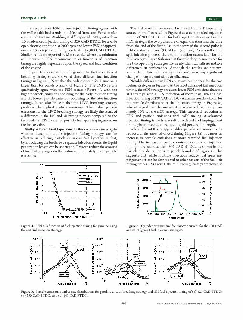
function of fuel injection timing and breathing strategy inFigure 4. The dependence of FSN emissions upon fuel injectiontiming is similar for all three breathing strategies, with advancedtiming producing the highest FSN emissions and intermediatetiming having little effect. For the most retarded injection timing,a slight rise in FSN emissions is produced for the throttledcondition but not for the other breathing strategies.
Figure 3. Efficiency and gaseous emissions for sDI gasoline operationunder the throttled, EIVC and LIVC breathing strategies, throttled sDIoperation with E20 and E85, and throttled PFI operation with gasoline.
This response of FSN to fuel injection timing agrees withthe well-established trends in published literature. For a similarengine architecture, Worlding et al.24 reported FSN greater than1.0 at advanced injection timing of 320 CAD BTDCf for a wideopen throttle condition at 2000 rpm and lower FSN of approxi-mately 0.3 as injection timing is retarded to 300 CAD BTDCf.Similar trends are reported byMoore et al.,8 where the minimumand maximum FSN measurements as functions of injectiontiming are highly dependent upon the speed and load conditionof the engine.The particle size distributions for gasoline for the three different
breathing strategies are shown at three different fuel injectiontimings in Figure 5. Note that the ordinate scale for Figure 5a islarger than for panels b and c of Figure 5. The SMPS resultsqualitatively agree with the FSN results (Figure 4), with thehighest particle emissions occurring for the early injection timingand the lowest particle emissions occurring for the later injectiontimings. It can also be seen that the LIVC breathing strategyproduces the highest particle emissions. The higher particleemissions for the LIVC breathing strategy are likely the result ofa difference in the fuel and air mixing process compared to thethrottled and EIVC cases or possibly fuel spray impingement onthe intake valve.MultipleDirect Fuel Injections. In this section, we investigate
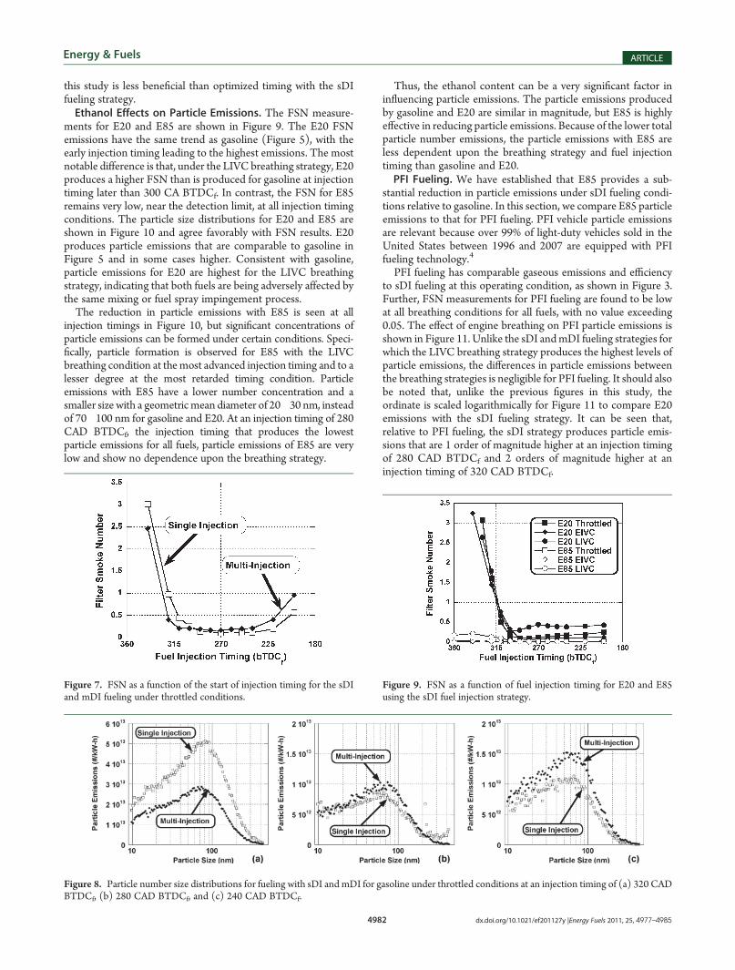
whether using a multiple injection fueling strategy can beeffective in reducing particle emissions. We hypothesize that,by introducing the fuel in two separate injection events, the liquidpenetration length can be shortened. This can reduce the amountof fuel that impinges on the piston and ultimately lower particleemissions.
The fuel injection command for the sDI and mDI operatingstrategies are illustrated in Figure 6 at a commanded injectiontiming of 280 CAD BTDC for both injection strategies. For themDI strategy, the two pulses are of equal duration and the timefrom the end of the first pulse to the start of the second pulse isheld constant at 1 ms (9 CAD at 1500 rpm). As a result of thesplit injection process, the end of injection occurs later for themDI strategy. Figure 6 shows that the cylinder pressure traces forthe two operating strategies are nearly identical with no notabledifferences in performance. Although the results are not pre-sented here, this mDI strategy does not cause any significantchanges in engine emissions or efficiency.Notable differences in FSN emissions can be seen for the two
fueling strategies in Figure 7. At the most advanced fuel injectiontiming, the mDI strategy produces lower FSN emissions than thesDI strategy, with a FSN reduction of more than 50% at a fuelinjection timing of 320 CADBTDCf. A similar trend is shown forthe particle distributions at this injection timing in Figure 8a,where the peak particle concentration is also reduced by approxi-mately 50% for the mDI strategy. This successful reduction inFSN and particle emissions with mDI fueling at advancedinjection timing is likely a result of reduced fuel impingementon the piston because of reduced liquid penetration length.While the mDI strategy enables particle emissions to be
reduced at the most advanced timing (Figure 8a), it causes anincrease in particle emissions at more retarded fuel injectiontiming. The increase in particle emissions occurs for injectiontiming more retarded than 300 CAD BTDCf, as shown in theparticle size distributions in panels b and c of Figure 8. Thissuggests that, while multiple injections reduce fuel spray im-pingement, it can be detrimental to other aspects of the fuel�airmixing process. As a result, the mDI fueling strategy employed in
Figure 5. Particle emission number size distributions for gasoline at each breathing strategy and sDI fuel injection timing of (a) 320 CAD BTDCf,(b) 280 CAD BTDCf, and (c) 240 CAD BTDCf.
Figure 6. Cylinder pressure and fuel injector current for the sDI (red)and mDI (green) fuel injection strategies.
Figure 4. FSN as a function of fuel injection timing for gasoline usingthe sDI fuel injection strategy.
this study is less beneficial than optimized timing with the sDIfueling strategy.Ethanol Effects on Particle Emissions. The FSN measure-
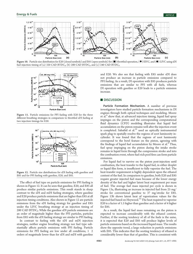
ments for E20 and E85 are shown in Figure 9. The E20 FSNemissions have the same trend as gasoline (Figure 5), with theearly injection timing leading to the highest emissions. The mostnotable difference is that, under the LIVC breathing strategy, E20produces a higher FSN than is produced for gasoline at injectiontiming later than 300 CA BTDCf. In contrast, the FSN for E85remains very low, near the detection limit, at all injection timingconditions. The particle size distributions for E20 and E85 areshown in Figure 10 and agree favorably with FSN results. E20produces particle emissions that are comparable to gasoline inFigure 5 and in some cases higher. Consistent with gasoline,particle emissions for E20 are highest for the LIVC breathingstrategy, indicating that both fuels are being adversely affected bythe same mixing or fuel spray impingement process.The reduction in particle emissions with E85 is seen at all
injection timings in Figure 10, but significant concentrations ofparticle emissions can be formed under certain conditions. Speci-fically, particle formation is observed for E85 with the LIVCbreathing condition at themost advanced injection timing and to alesser degree at the most retarded timing condition. Particleemissions with E85 have a lower number concentration and asmaller size with a geometric mean diameter of 20�30 nm, insteadof 70�100 nm for gasoline and E20. At an injection timing of 280CAD BTDCf, the injection timing that produces the lowestparticle emissions for all fuels, particle emissions of E85 are verylow and show no dependence upon the breathing strategy.
Thus, the ethanol content can be a very significant factor ininfluencing particle emissions. The particle emissions producedby gasoline and E20 are similar in magnitude, but E85 is highlyeffective in reducing particle emissions. Because of the lower totalparticle number emissions, the particle emissions with E85 areless dependent upon the breathing strategy and fuel injectiontiming than gasoline and E20.PFI Fueling. We have established that E85 provides a sub-
stantial reduction in particle emissions under sDI fueling condi-tions relative to gasoline. In this section, we compare E85 particleemissions to that for PFI fueling. PFI vehicle particle emissionsare relevant because over 99% of light-duty vehicles sold in theUnited States between 1996 and 2007 are equipped with PFIfueling technology.4
PFI fueling has comparable gaseous emissions and efficiencyto sDI fueling at this operating condition, as shown in Figure 3.Further, FSN measurements for PFI fueling are found to be lowat all breathing conditions for all fuels, with no value exceeding0.05. The effect of engine breathing on PFI particle emissions isshown in Figure 11. Unlike the sDI andmDI fueling strategies forwhich the LIVC breathing strategy produces the highest levels ofparticle emissions, the differences in particle emissions betweenthe breathing strategies is negligible for PFI fueling. It should alsobe noted that, unlike the previous figures in this study, theordinate is scaled logarithmically for Figure 11 to compare E20emissions with the sDI fueling strategy. It can be seen that,relative to PFI fueling, the sDI strategy produces particle emis-sions that are 1 order of magnitude higher at an injection timingof 280 CAD BTDCf and 2 orders of magnitude higher at aninjection timing of 320 CAD BTDCf.
Figure 8. Particle number size distributions for fueling with sDI and mDI for gasoline under throttled conditions at an injection timing of (a) 320 CADBTDCf, (b) 280 CAD BTDCf, and (c) 240 CAD BTDCf.
Figure 9. FSN as a function of fuel injection timing for E20 and E85using the sDI fuel injection strategy.
Figure 7. FSN as a function of the start of injection timing for the sDIand mDI fueling under throttled conditions.
The effect of fuel type on particle emissions for PFI fueling isshown in Figure 12. It can be seen that gasoline, E20, and E85 allproduce similar particle emissions. This result stands in sharpcontrast to the sDI and mDI fueling strategies, where gasolineand E20 produce particle emissions that are higher than E85 at allinjection timing conditions. Also shown in Figure 12 are particleemissions from the sDI fueling strategy for gasoline and E85under the LIVC breathing strategy at an injection timing of280 CAD BTDCf. While the gasoline sDI particle emissions arean order of magnitude higher than the PFI particles, particlesfrom E85 with the sDI fueling strategy are similar to PFI fueling.In contrast to fueling with the sDI and mDI injection
strategies, neither engine breathing strategy nor fuel type sub-stantially affects particle emissions with PFI fueling. Particleemissions for PFI fueling are low under all conditions, 1�2orders of magnitude lower than for sDI and mDI with gasoline
and E20. We also see that fueling with E85 under sDI doesnot produce an increase in particle emissions compared toPFI fueling. As a result, DI operation with E85 produces particleemissions that are similar to PFI with all fuels, whereasDI operation with gasoline or E20 leads to a particle emissionincrease.
’DISCUSSION
Particle Formation Mechanism. A number of previousinvestigators have studied particle formation mechanisms in DIengines through both optical techniques and modeling. Mooreet al.8 show that, at advanced injection timing, liquid fuel sprayimpinges on the piston and the corresponding computationalfluid dynamics (CFD) modeling illustrates that liquid fuelaccumulation on the piston remains well after the injection eventis completed. Sabathil et al.32 used an optically instrumentedspark plug to spatially resolve the regions of soot luminosity in-cylinder. It was found that the regions of soot luminositycorrespond to the bowl feature on the piston, agreeing withthe findings of liquid fuel accumulation by Moore et al.8 Thus,fuel spray impinging on the piston during the intake strokeremains in liquid form through the compression stroke and intothe combustion event, where fuel-rich pool fires can form particleemissions.For liquid fuel to survive on the piston post-injection until
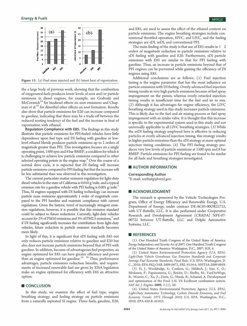
combustion, the heat transfer to the liquid fuel, in either dropletor liquid film form, is insufficient to fully vaporize the fuel. Theheat-transfer requirement is highly dependent upon the ethanolcontent of the fuel. In comparison to gasoline, both E20 and E85require greater injected fuel mass because of the lower energydensity of the fuel and higher latent heat requirement per massof fuel. The average fuel mass injected per cycle is shown inFigure 13a, illustrating an increase in injected fuel from 25 mg/stroke for conventional gasoline to 37 mg/stroke for E85.Figure 13b shows latent heat of vaporization values for theinjected fuel based on Heywood.33 The heat required to vaporizeE20 is a factor of 1.5 higher than gasoline and a factor of 4 higherfor E85.As a result, the liquid fuel mass remaining on the piston is
expected to increase considerably with the ethanol content.Further, if the sooting tendency of all of the fuels is the same,it is expected that E20 and E85 will produce higher levels ofparticle emissions based on the increased liquid mass. The resultsshow the opposite trend, a large reduction in particle emissionswith E85. This indicates that the sooting tendency of ethanol isconsiderably lower than that of gasoline. This is consistent with
Figure 10. Particle size distribution for E20 (closed symbols) and E85 (open symbols) for (9) throttled operation, ([) EIVC, and (b) LIVC using sDIfuel injection timing of (a) 320 CAD BTDCf, (b) 280 CAD BTDCf, and (c) 240 CAD BTDCf.
Figure 11. Particle emissions for PFI fueling with E20 for the threedifferent breathing strategies in comparison to throttled sDI fueling attwo injection timings for E20.
Figure 12. Particle size distributions for sDI fueling with gasoline andE85 and for PFI fueling with gasoline, E20, and E85.
the a large body of previous work, showing that the combustionof oxygenated fuels produces lower levels of soot and/or particleemissions in diesel engines, for example, see Graboski andMcCormick34 for biodiesel effects on soot emissions and Chap-man et al.35 for dimethyl ether effects on soot formation. Resultsalso show that particle emissions for E20 can increase comparedto gasoline, indicating that there may be a trade-off between thereduced sooting tendency of the fuel and the increase in heat ofvaporization with ethanol.Regulation Compliance with E85. The findings in this study
illustrate that particle emissions for PFI-fueled vehicles have littledependence upon fuel type and DI fueling with gasoline or low-level ethanol blends produces particle emissions up to 2 orders ofmagnitude greater than PFI. This investigation focuses on a singleoperating point, 1500 rpm and8 bar BMEP, a condition forwhich itis challenging to achieve low particle emissions compared to otherselected operating points in the engine map.8 Over the course of anormal drive cycle, it is expected that DI fueling will increaseparticle emissions compared to PFI fueling but that the increase willbe less substantial than was observed in this investigation.The current particulate matter emission regulation for light-duty
diesel vehicles in the state of California is 0.010 g/mile, and a typicalemission rate for a gasoline vehicle with PFI fueling is 0.001 g/mile.5
Thus, SI engines equipped with DI fueling technology can increaseparticle mass emissions approximately 1 order of magnitude com-pared to the PFI baseline and maintain compliance with currentregulations. Given the historic trend of increasingly stringent emis-sion regulations, however, it is possible that this emission standardcould be subject to future reductions. Currently, light-duty vehiclesaccount for 2%of PM10 emissions and 3%of PM2.5 emissions,5 andif DI fueling significantly increases the contribution from light-dutyvehicles, future reduction in particle emission standards becomesmore likely.In light of this, it is significant that sDI fueling with E85 not
only reduces particle emissions relative to gasoline and E20 butalso does not increase particle emissions beyond that of PFI withgasoline. In addition, because of advantageous fuel properties, anengine optimized for E85 can have greater efficiency and powerthan an engine optimized for gasoline.14�18 Thus, performanceadvantages, particle emissions reduction benefits, and require-ments of increased renewable fuel use given by EISA legislationmake an engine optimized for efficiency with E85 an attractiveoption.
’CONCLUSION
In this study, we examine the effect of fuel type, enginebreathing strategy, and fueling strategy on particle emissionsfrom a naturally aspirated SI engine. Three fuels, gasoline, E20,
and E85, are used to assess the effect of the ethanol content onparticle emissions. The engine breathing strategies include con-ventional throttled operation, EIVC, and LIVC, and the fuelingstrategies are sDI, mDI, and conventional PFI.
The main finding of the study is that use of E85 results in 1�2orders of magnitude reduction in particle emissions relative tosDI fueling with gasoline and E20. Furthermore, sDI particleemissions with E85 are similar to that for PFI fueling withgasoline. Thus, an increase in particle emissions beyond that ofPFI engines can be prevented while gaining the efficiency of DIengines using E85.
Additional conclusions are as follows: (1) Fuel injectiontiming is the engine parameter that has the most influence onparticle emissions with DI fueling. Overly advanced fuel injectiontiming results in very high particle emissions because of fuel sprayimpingement on the piston, whereas overly retarded injectiontiming results in insufficient time for the fuel and air to mix.(2) Although it has advantages for engine efficiency, the LIVCbreathing strategy used in this study increases particle emissions.This is likely due to the fuel and air mixing process or fuel sprayimpingement with an intake valve. It is thought that this increaseis specific to the experimental system used in this study and notuniversally applicable to all LIVC breathing strategies. (3) Whilethe mDI fueling strategy employed here is effective in reducingparticles at overly advanced injection timing, this strategy resultsin higher particle emissions than the sDI strategy at more optimalinjection timing conditions. (4) The PFI fueling strategy pro-duces very low levels of particle emissions at 1500 rpm and 8 barBMEP. Particle emissions for PFI fueling are found to be similarfor all fuels and breathing strategies investigated.
The research is sponsored by the Vehicle Technologies Pro-gram, Office of Energy Efficiency and Renewable Energy, U.S.Department of Energy, under contract DE-AC05-00OR22725,with UT-Battelle, LLC. It is also performed under CooperativeResearch and Development Agreement (CRADA) NFE-07-00722 between UT-Battelle, LLC and Delphi AutomotiveSystems, LLC.
’REFERENCES
(1) One Hundred Tenth Congress of the United States of America.Energy Independence and Security Act of 2007; OneHundredTenthCongressof the United States of America: Washington, D.C., 2007; H.R. 6.
(2) United States Environmental Protection Agency (U.S. EPA).Light-Duty Vehicle Greenhouse Gas Emission Standards and CorporateAverage Fuel Economy Standards; Final Rule; U.S. EPA: Washington, D.C., 2010; EPA-HQ-OAR-2009-0472, FRL-9134-6, NHTSA-2009-0059.
(3) Yi, J.; Wooldridge, S.; Coulson, G.; Hilditch, J.; Iyer, C. O.;Moilanen, P.; Papaioannou, G.; Reiche, D.; Shelby, M.; VanDerWege,B.; Weaver, C.; Xu, Z.; Davis, G.; Hinds, B.; Schamel, A. Developmentand optimization of the Ford 3.5L V6 EcoBoost combustion system.SAE Int. J. Engines 2009, 2 (1), 20.
(4) United States Environmental Protection Agency (U.S. EPA).Light-Duty Automotive Technology, Carbon Dioxide Emissions, and FuelEconomy Trends: 1975 Through 2010; U.S. EPA: Washington, D.C.,2010; EPA-420-R-10-023.
Figure 13. (a) Fuel mass injected and (b) latent heat of vaporization.
(5) State of California Air Resources Board. Preliminary DiscussionPaper—Proposed Amendments to California’s Low-Emission Vehicle Reg-ulations—Particulate Matter Mass, Ultrafine Solid Particle Number, andBlack Carbon Emissions; State of California Air Resources Board:Sacramento, CA, 2010; http://www.arb.ca.gov/msprog/levprog/leviii/meetings/051810/pm_disc_paper-v6.pdf.(6) Aakko, P.; Nylund, N.-O. Particle emissions at moderate and
cold temperatures using different fuels. SAE [Tech. Pap.] 2003, DOI:10.4271/2003-01-3285.(7) Aikawa, K.; Sakurai, T.; Jetter, J. J. Development of a predictive
model for gasoline vehicle particulatematter emissions. SAE [Tech. Pap.]2010, DOI: 10.4271/2010-01-2115.(8) Moore, W.; Foster, M.; Lai, M.-C.; Xie, X.-B.; Zheng, Y.;
Matsumoto, A. Charge motion benefits of valve deactivation to reducefuel consumption and emissions in a GDi, VVA engine. SAE [Tech. Pap.]2011, DOI: 10.4271/2011-01-1221.(9) Hedge, M.; Weber, P.; Gingrich, J.; Alger, T.; Khalek, I. A. Effect
of EGR on particle emissions from aGDI engine. SAE [Tech. Pap.] 2011,DOI: 10.4271/2011-01-0636.(10) Iyer, C. O.; Yi, J. Spray pattern optimization for the Duratec 3.5L
effects on direct-injection spark-ignition gasoline vehicle particulatematter emissions. SAE Int. J. Engines 2010, 3 (2), 650–659.(12) He, X.; Ireland, J. C.; Zigler, B. T.; Ratcliff, M. A.; Knoll, K. E.;
Alleman, T. L.; Tester, J. T. The impacts of mid-level biofuel content ingasoline on SIDI engine-out and tailpipe particulate matter emissions.SAE [Tech. Pap.] 2010, DOI: 10.4271/2010-01-2125.(13) Khalek, I. A.; Bougher, T. Particle emissions from a 2009
gasoline direct injection engine using different commercially availablefuels. SAE [Tech. Pap.] 2010, DOI: 10.4271/2010-01-2117.(14) Wu, K.-J. The Use of Exhaust Gas Recirculation to Optimize Fuel
Economy and Minimize Emissions in Engines Operating on E85 Fuel; U.S.Department of Energy: Washington, D.C., 2009; Vehicle TechnologiesAnnual Merit Review, Fuels Technologies Review FT-10.(15) Kilmurray, P.DoE Optimally Controlled Flexible Fuel Powertrain
System; U.S. Department of Energy: Washington, D.C., 2009; VehicleTechnologies Annual Merit Review, Fuels Technologies Review FT-11.(16) Yilmaz, H. DOE Merit Review—Flex Fuel Vehicle Systems; U.S.
through Boosting, Spray Optimized GDi, VCR and Variable Valvetrain;U.S. Department of Energy: Washington, D.C., 2009; Vehicle Technol-ogies Annual Merit Review, Fuels Technologies Review FT-14.(18) Agarwal, A.; Whitaker, P. E85 Optimized Engine; U.S. Depart-
ment of Energy: Washington, D.C., 2009; Vehicle Technologies AnnualMerit Review, Fuels Technologies Review FT-12.(19) Hoyer, K.;Moore,W.; Confer, K. A simulationmethod to guide
DISI engine redesign for increased efficiency using alcohol fuel blends.SAE [Tech. Pap.] 2010, DOI: 10.4271/2010-01-1203.(20) Moore, W.; Foster, M.; Hoyer, K. Engine efficiency improve-
ments enabled by ethanol fuel blends in a GDi VVA flex fuel engine. SAE[Tech. Pap.] 2011, DOI: 10.4271/2011-01-0900.(21) Szybist, J.; Youngquist, A.; Wagner, R.; Foster, M.; Moore, W.;
Confer, K. Investigation of knock limited compression ratio of ethanolgasoline blends. SAE [Tech. Pap.] 2010, DOI: 10.4271/2010-01-0619.(22) Cleary, D.; Silvas, G. Unthrottled engine operation with vari-
able intake valve lift, duration, and timing. SAE [Tech. Pap.] 2007, DOI:10.4271/2007-01-1282.(23) AVL List GmbH. AVL 415S Variable Smoke Meter Operating
Manual, AT1240E, Rev. 05; AVL List GmbH: Graz, Austria, 2005.(24) Woldring, D.; Landenfeld, T.; Christiem, M. J. DI boost:
Application of a high performance gasoline direct injection concept.SAE [Tech. Pap.] 2007, DOI: 10.4271/2007-01-1410.(25) Abdul-Khalek, I. S.; Kittleson, D. B.; Graskow, B. R.; Wei, Q.
(26) Giechaskiel, B.; Dilara, P.; Sandbach, E.; Andersson, J. Particlemeasurement programme (PMP) light-duty inter-laboratory exercise:Comparison of different particle number measurement systems. Meas.Sci. Technol. 2008, 19, 9.
(27) Bechtold, R.; Thomas, J. F.; Huff, S. P.; Szybist, J.; Theiss, T.;West, B.; Goodman, M.; Timbario, T. A. Technical Issues Associated withthe Use of Intermediate Ethanol Blends (>E10) in the U.S. Legacy Fleet:Assessment of Prior Studies; Oak Ridge National Laboratory: Knoxville,TN, 2007; ORNL/TM-2007/37, https://portal.ornl.gov/sites/apps/PTS/PtsDocs/Publication%207767.pdf.
(28) Nakama, K.; Kusaka, J.; Daisho, Y. Effect of ethanol on knock inspark ignition gasoline engines. SAE [Tech. Pap.] 2008, DOI: 10.4271/2008-32-0200.
(29) Nakata, K.; Utsumi, S.; Ota, A.; Kawatake, K.; Kawai, T.;Tsunooka, T. The effect of ethanol fuel on a spark ignition engine.SAE [Tech. Pap.] 2006, DOI: 10.4271/2006-01-3380.
(30) West, B.; Lopez, A.; Theiss, T.; Graves, R.; Storey, J.; Lewis, S.Fuel economy and emissions of the ethanol-optimized Saab 9-5 bio-power. SAE [Tech. Pap.] 2007, DOI: 10.4271/2007-01-3994.
(31) Datta, R.; Maher, M.; Jones, C.; Brinker, R. Ethanol—Theprimary renewable liquid fuel. J. Chem. Technol. Biotechnol. 2011,86, 473–480.
(32) Sabathil, D.; Koenigstein, A.; Schaffner, P.; Fritzsche, J.; Doehler,A. The influence of DISI engine operating parameters on particle numberemissions. SAE [Tech. Pap.] 2011, DOI: 10.4271/2011-01-0143.
(33) Heywood, J. B. Internal Combustion Engine Fundamentals;McGraw-Hill Book Company: New York, 1988; p 930.
(34) Graboski, M. S.; McCormick, R. L. Combustion of fat andvegetable oil derived fuels in diesel engines. Prog. Energy Combust. Sci.1998, 24, 125–164.
(35) Chapman, E.M.; Boehman, A. L.; Tijm, P.;Waller, F. Emissionscharacteristics of a Navistar 7.3L turbodiesel fueled with blends ofdimethyl ether and diesel fuel. SAE [Tech. Pap.] 2001, DOI: 10.4271/2001-01-3626.