EtherCAT for S300/S400/S600/S700 Communication Profile Fieldbus Interface Translation of the original manual Edition 12/2010 Keep the manual as a product component during the life span of the product. Pass the manual to future users / owners of the product. Datei srethercat_e.***
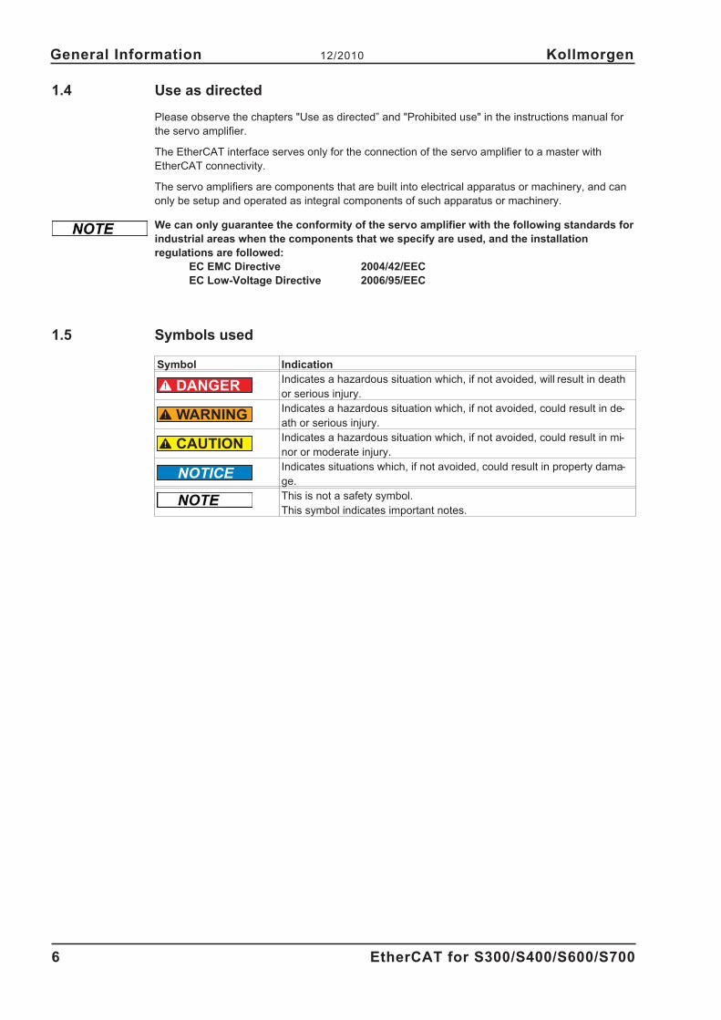
Transcript
EtherCAT for S300/S400/S600/S700
Communication Profile
Fieldbus Interface
Translation of the original manual
Edition 12/2010
Keep the manual as a product component
during the life span of the product.
Pass the manual to future users / owners
of the product.
Datei srethercat_e.***
Record of revisions :
Edition Remarks
10/2007 First edition
12/2009 S700 with EC onboard, symbols acc. to ANSI Z535.6B, randing, several minor corrections
12/2010 Company name
SERVOSTAR is a registered trademark of Kollmorgen Corporation
EtherCAT is a registered trademark of EtherCAT Technology Group
Technical changes which improve the performance of the equipment may be made without prior notice !
Printed in the Federal Republic of Germany
All rights reserved. No part of this work may be reproduced in any form (by photocopying, microfilm or any
other method) or stored, processed, copied or distributed by electronic means without the written permission of
AL Control Event 0x204 0 r/w rActivation of AL control event for phase
run-up
- 0x204 1 r/w r ReservedDC Distributed
Clock0x204 2 r/w r
Activation of distributed clock (DC) interrupts
for entire communication
- 0x204 3...7 r/w r Reserved
Mail Out Event 0x205 0 r/w rActivation of output event mailbox (SDO,
Sync Manager 0) for object channel.
Mail In Event 0x205 1 r/w rActivation of input event mailbox (SDO, Sync
Manager 1) for object channel.
Pro Out Event 0x205 2 r/w rActivation of output event process data
(PDO, card's cyclical setpoints)
Pro In Event 0x205 3 r/w rActivation of input event process data (PDO,
servo amplifier's cyclical actual values)
- 0x205 4...7 r/w r Reserved
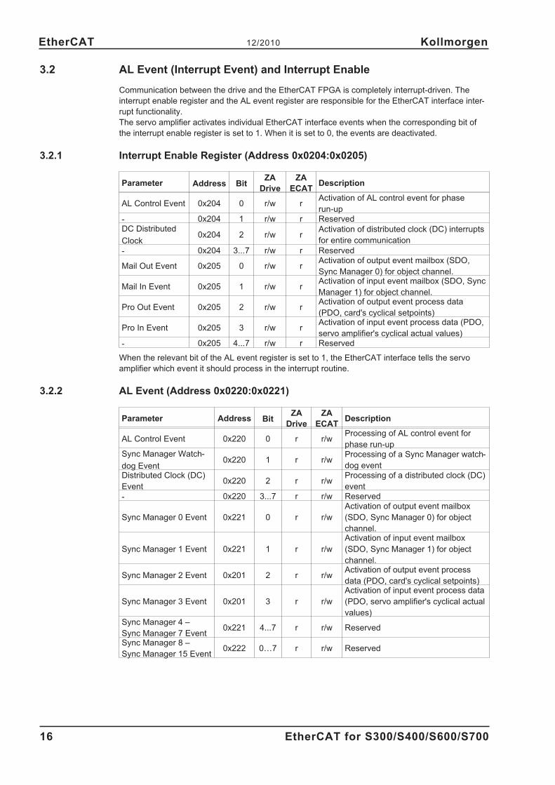
When the relevant bit of the AL event register is set to 1, the EtherCAT interface tells the servo
amplifier which event it should process in the interrupt routine.
3.2.2 AL Event (Address 0x0220:0x0221)
Parameter Address BitZA
Drive
ZA
ECATDescription
AL Control Event 0x220 0 r r/wProcessing of AL control event for
phase run-upSync Manager Watch-
dog Event0x220 1 r r/w
Processing of a Sync Manager watch-
dog eventDistributed Clock (DC)
Event0x220 2 r r/w
Processing of a distributed clock (DC)
event
- 0x220 3...7 r r/w Reserved
Sync Manager 0 Event 0x221 0 r r/w
Activation of output event mailbox
(SDO, Sync Manager 0) for object
channel.
Sync Manager 1 Event 0x221 1 r r/w
Activation of input event mailbox
(SDO, Sync Manager 1) for object
channel.
Sync Manager 2 Event 0x201 2 r r/wActivation of output event process
data (PDO, card's cyclical setpoints)
Sync Manager 3 Event 0x201 3 r r/w
Activation of input event process data
(PDO, servo amplifier's cyclical actual
values)Sync Manager 4 –
Sync Manager 7 Event0x221 4...7 r r/w Reserved
Sync Manager 8 –
Sync Manager 15 Event0x222 0…7 r r/w Reserved
16 EtherCAT for S300/S400/S600/S700
EtherCAT 12/2010 Kollmorgen
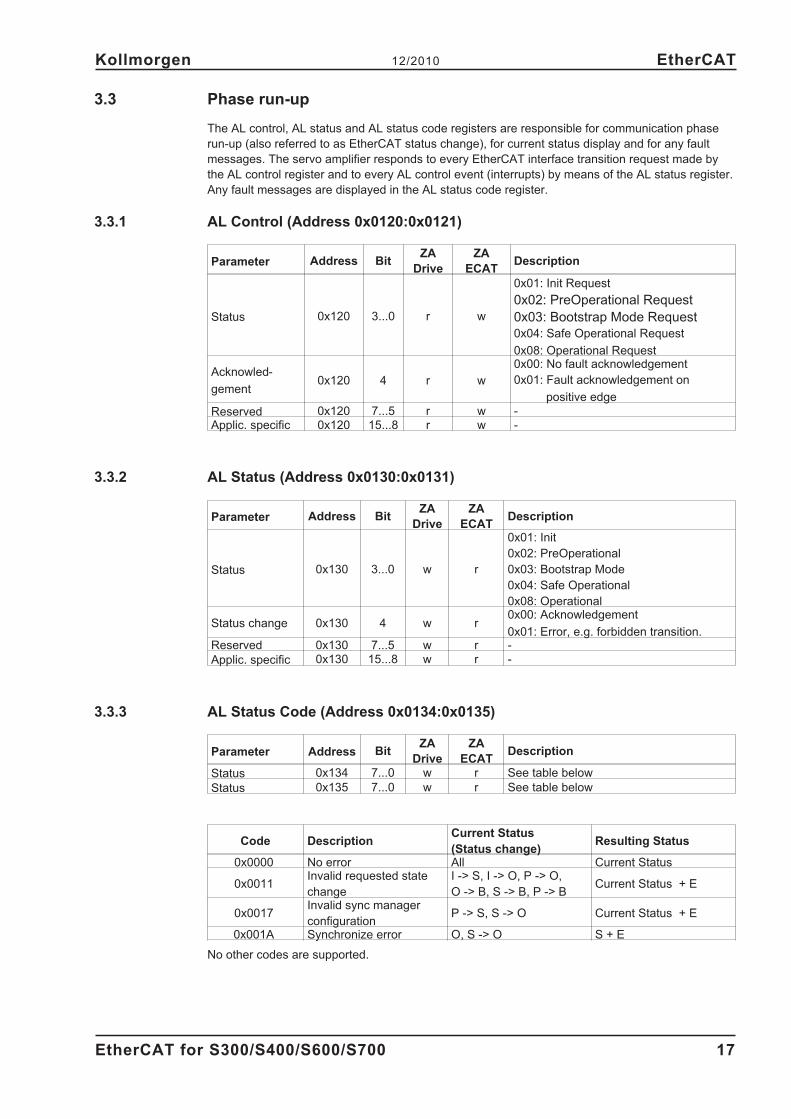
3.3 Phase run-up
The AL control, AL status and AL status code registers are responsible for communication phase
run-up (also referred to as EtherCAT status change), for current status display and for any fault
messages. The servo amplifier responds to every EtherCAT interface transition request made by
the AL control register and to every AL control event (interrupts) by means of the AL status register.
Any fault messages are displayed in the AL status code register.
3.3.1 AL Control (Address 0x0120:0x0121)
Parameter Address BitZA
Drive
ZA
ECATDescription
Status 0x120 3...0 r w
0x01: Init Request
0x02: PreOperational Request
0x03: Bootstrap Mode Request
0x04: Safe Operational Request
0x08: Operational Request
Acknowled-
gement0x120 4 r w
0x00: No fault acknowledgement
0x01: Fault acknowledgement on
positive edge
Reserved 0x120 7...5 r w -Applic. specific 0x120 15...8 r w -
3.3.2 AL Status (Address 0x0130:0x0131)
Parameter Address BitZA
Drive
ZA
ECATDescription
Status 0x130 3...0 w r
0x01: Init
0x02: PreOperational
0x03: Bootstrap Mode
0x04: Safe Operational
0x08: Operational
Status change 0x130 4 w r0x00: Acknowledgement
0x01: Error, e.g. forbidden transition.Reserved 0x130 7...5 w r -
Applic. specific 0x130 15...8 w r -
3.3.3 AL Status Code (Address 0x0134:0x0135)
Parameter Address BitZA
Drive
ZA
ECATDescription
Status 0x134 7...0 w r See table below
Status 0x135 7...0 w r See table below
Code DescriptionCurrent Status
(Status change)Resulting Status
0x0000 No error All Current Status
0x0011Invalid requested state
change
I -> S, I -> O, P -> O,
O -> B, S -> B, P -> BCurrent Status + E
0x0017Invalid sync manager
configurationP -> S, S -> O Current Status + E
0x001A Synchronize error O, S -> O S + E
No other codes are supported.
EtherCAT for S300/S400/S600/S700 17
Kollmorgen 12/2010 EtherCAT
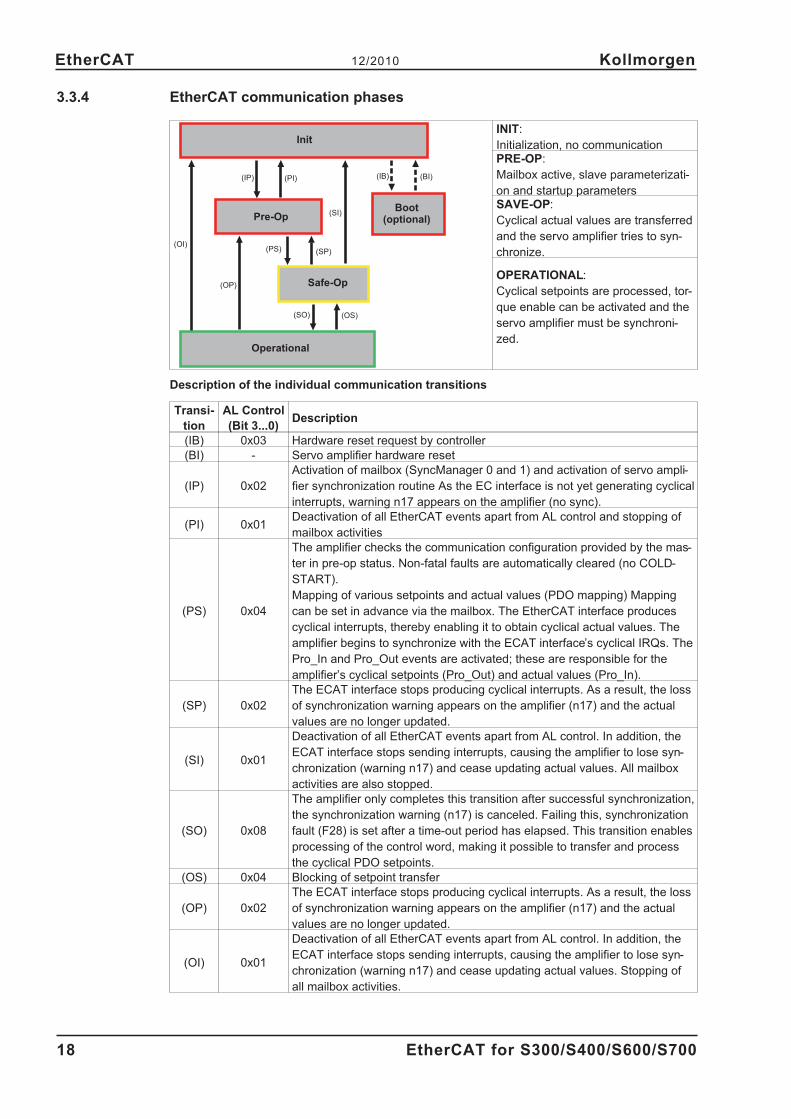
3.3.4 EtherCAT communication phases
INIT:
Initialization, no communicationPRE-OP:
Mailbox active, slave parameterizati-
on and startup parametersSAVE-OP:
Cyclical actual values are transferred
and the servo amplifier tries to syn-
chronize.
OPERATIONAL:
Cyclical setpoints are processed, tor-
que enable can be activated and the
servo amplifier must be synchroni-
zed.
Description of the individual communication transitions
Transi-
tion
AL Control
(Bit 3...0)Description
(IB) 0x03 Hardware reset request by controller
(BI) - Servo amplifier hardware reset
(IP) 0x02
Activation of mailbox (SyncManager 0 and 1) and activation of servo ampli-
fier synchronization routine As the EC interface is not yet generating cyclical
interrupts, warning n17 appears on the amplifier (no sync).
(PI) 0x01Deactivation of all EtherCAT events apart from AL control and stopping of
mailbox activities
(PS) 0x04
The amplifier checks the communication configuration provided by the mas-
ter in pre-op status. Non-fatal faults are automatically cleared (no COLD-
START).
Mapping of various setpoints and actual values (PDO mapping) Mapping
can be set in advance via the mailbox. The EtherCAT interface produces
cyclical interrupts, thereby enabling it to obtain cyclical actual values. The
amplifier begins to synchronize with the ECAT interface’s cyclical IRQs. The
Pro_In and Pro_Out events are activated; these are responsible for the
amplifier’s cyclical setpoints (Pro_Out) and actual values (Pro_In).
(SP) 0x02
The ECAT interface stops producing cyclical interrupts. As a result, the loss
of synchronization warning appears on the amplifier (n17) and the actual
values are no longer updated.
(SI) 0x01
Deactivation of all EtherCAT events apart from AL control. In addition, the
ECAT interface stops sending interrupts, causing the amplifier to lose syn-
chronization (warning n17) and cease updating actual values. All mailbox
activities are also stopped.
(SO) 0x08
The amplifier only completes this transition after successful synchronization,
the synchronization warning (n17) is canceled. Failing this, synchronization
fault (F28) is set after a time-out period has elapsed. This transition enables
processing of the control word, making it possible to transfer and process
the cyclical PDO setpoints.
(OS) 0x04 Blocking of setpoint transfer
(OP) 0x02
The ECAT interface stops producing cyclical interrupts. As a result, the loss
of synchronization warning appears on the amplifier (n17) and the actual
values are no longer updated.
(OI) 0x01
Deactivation of all EtherCAT events apart from AL control. In addition, the
ECAT interface stops sending interrupts, causing the amplifier to lose syn-
chronization (warning n17) and cease updating actual values. Stopping of
all mailbox activities.
18 EtherCAT for S300/S400/S600/S700
EtherCAT 12/2010 Kollmorgen
(IP) (PI) (IB) (BI)
(OI)
(OP)
(PS) (SP)
(SI)
(SO) (OS)
Init
Pre-OpBoot
(optional)
Safe-Op
Operational
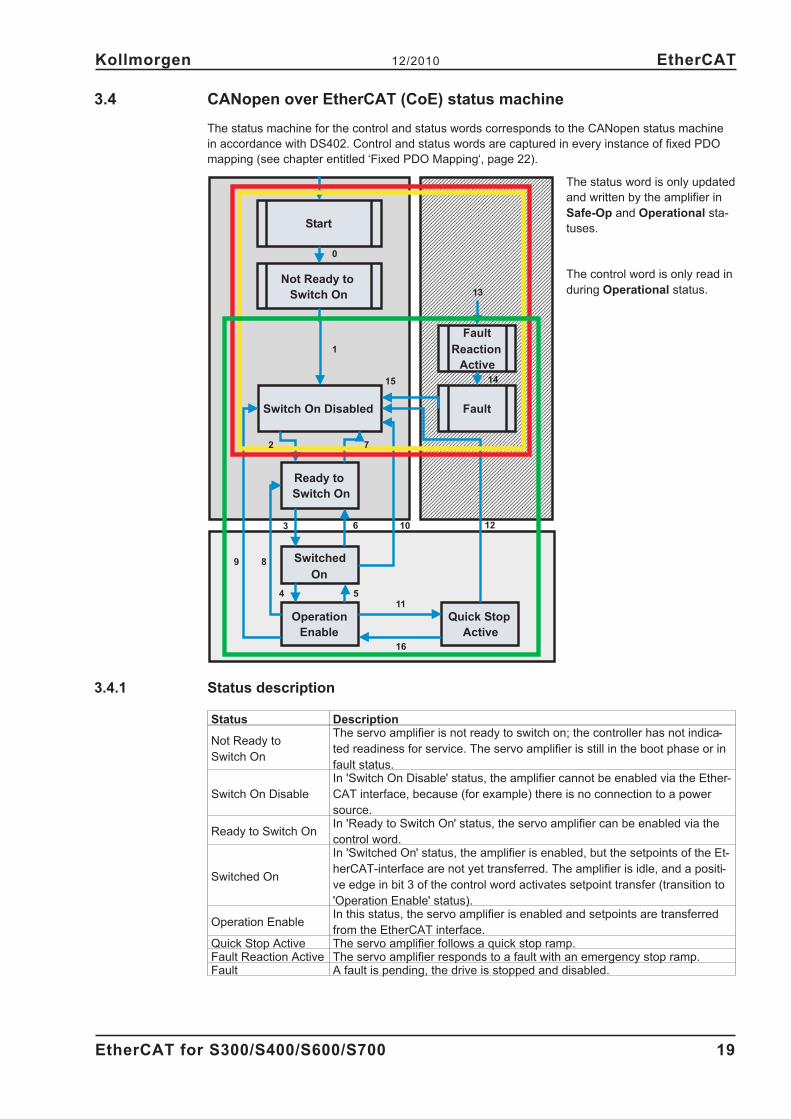
3.4 CANopen over EtherCAT (CoE) status machine
The status machine for the control and status words corresponds to the CANopen status machine
in accordance with DS402. Control and status words are captured in every instance of fixed PDO
mapping (see chapter entitled ‘Fixed PDO Mapping‘, page 22).
The status word is only updated
and written by the amplifier in
Safe-Op and Operational sta-
tuses.
The control word is only read in
during Operational status.
3.4.1 Status description
Status Description
Not Ready to
Switch On
The servo amplifier is not ready to switch on; the controller has not indica-
ted readiness for service. The servo amplifier is still in the boot phase or in
fault status.
Switch On Disable
In 'Switch On Disable' status, the amplifier cannot be enabled via the Ether-
CAT interface, because (for example) there is no connection to a power
source.
Ready to Switch OnIn 'Ready to Switch On' status, the servo amplifier can be enabled via the
control word.
Switched On
In 'Switched On' status, the amplifier is enabled, but the setpoints of the Et-
herCAT-interface are not yet transferred. The amplifier is idle, and a positi-
ve edge in bit 3 of the control word activates setpoint transfer (transition to
'Operation Enable' status).
Operation EnableIn this status, the servo amplifier is enabled and setpoints are transferred
from the EtherCAT interface.Quick Stop Active The servo amplifier follows a quick stop ramp.Fault Reaction Active The servo amplifier responds to a fault with an emergency stop ramp.Fault A fault is pending, the drive is stopped and disabled.
EtherCAT for S300/S400/S600/S700 19
Kollmorgen 12/2010 EtherCAT
Start
Not Ready to
Switch On
Switch On Disabled
Ready to
Switch On
Switched
On
Operation
Enable
Quick Stop
Active
Fault
Reaction
Active
Fault
0
1
2 7
4 5
6
89
11
12
13
14
103
16
15
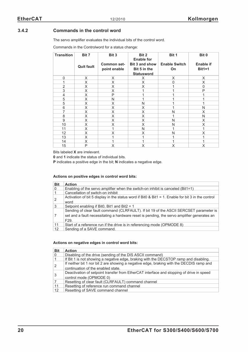
3.4.2 Commands in the control word
The servo amplifier evaluates the individual bits of the control word.
Commands in the Controlword for a status change:
Transition Bit 7 Bit 3 Bit 2 Bit 1 Bit 0
Quit faultCommon set-
point enable
Enable for
Bit 3 and show
Bit 5 in the
Statusword
Enable Switch
On
Enable if
Bit1=1
0 X X X X X1 X X X 0 X2 X X X 1 03 X X 1 1 P4 X P 1 1 15 X N 1 1 15 X X N 1 16 X X X 1 N7 X X X N X8 X X X 1 N9 X X X N X10 X X X N X11 X 1 N 1 112 X X X N X13 X 1 1 1 114 X 1 1 1 115 P X X X X
Bits labeled X are irrelevant.
0 and 1 indicate the status of individual bits.
P indicates a positive edge in the bit; N indicates a negative edge.
Actions on positive edges in control word bits:
Bit Action0 Enabling of the servo amplifier when the switch-on inhibit is canceled (Bit1=1)1 Cancellation of switch-on inhibit
2Activation of bit 5 display in the status word if Bit0 & Bit1 = 1. Enable for bit 3 in the control
word3 Setpoint enabling if Bit0, Bit1 and Bit2 = 1
7
Sending of clear fault command (CLRFAULT). If bit 19 of the ASCII SERCSET parameter is
set and a fault necessitating a hardware reset is pending, the servo amplifier generates an
F29.11 Start of a reference run if the drive is in referencing mode (OPMODE 8)12 Sending of a SAVE command.
Actions on negative edges in control word bits:
Bit Action0 Disabling of the drive (sending of the DIS ASCII command)1 If Bit 1 is not showing a negative edge, braking with the DECSTOP ramp and disabling.
2If neither bit 1 nor bit 2 are showing a negative edge, braking with the DECDIS ramp and
continuation of the enabled state.
3Deactivation of setpoint transfer from EtherCAT interface and stopping of drive in speed
control mode (OPMODE 0)7 Resetting of clear fault (CLRFAULT) command channel11 Resetting of reference run command channel12 Resetting of SAVE command channel
20 EtherCAT for S300/S400/S600/S700
EtherCAT 12/2010 Kollmorgen
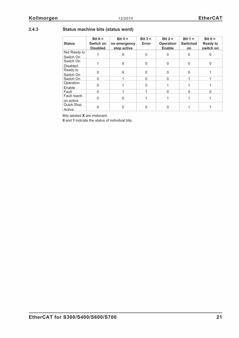
3.4.3 Status machine bits (status word)
Status
Bit 6 =
Switch on
Disabled
Bit 5 =
no emergency
stop active
Bit 3 =
Error
Bit 2 =
Operation
Enable
Bit 1 =
Switched
on
Bit 0 =
Ready to
switch onNot Ready to
Switch On1 X 0 0 0 0
Switch On
Disabled1 X 0 0 0 0
Ready to
Switch On0 X 0 0 0 1
Switch On 0 1 0 0 1 1Operation
Enable0 1 0 1 1 1
Fault 0 1 1 0 0 0Fault reacti-
on active0 0 1 1 1 1
Quick Stop
Active0 0 0 0 1 1
Bits labeled X are irrelevant.
0 and 1 indicate the status of individual bits.
EtherCAT for S300/S400/S600/S700 21
Kollmorgen 12/2010 EtherCAT
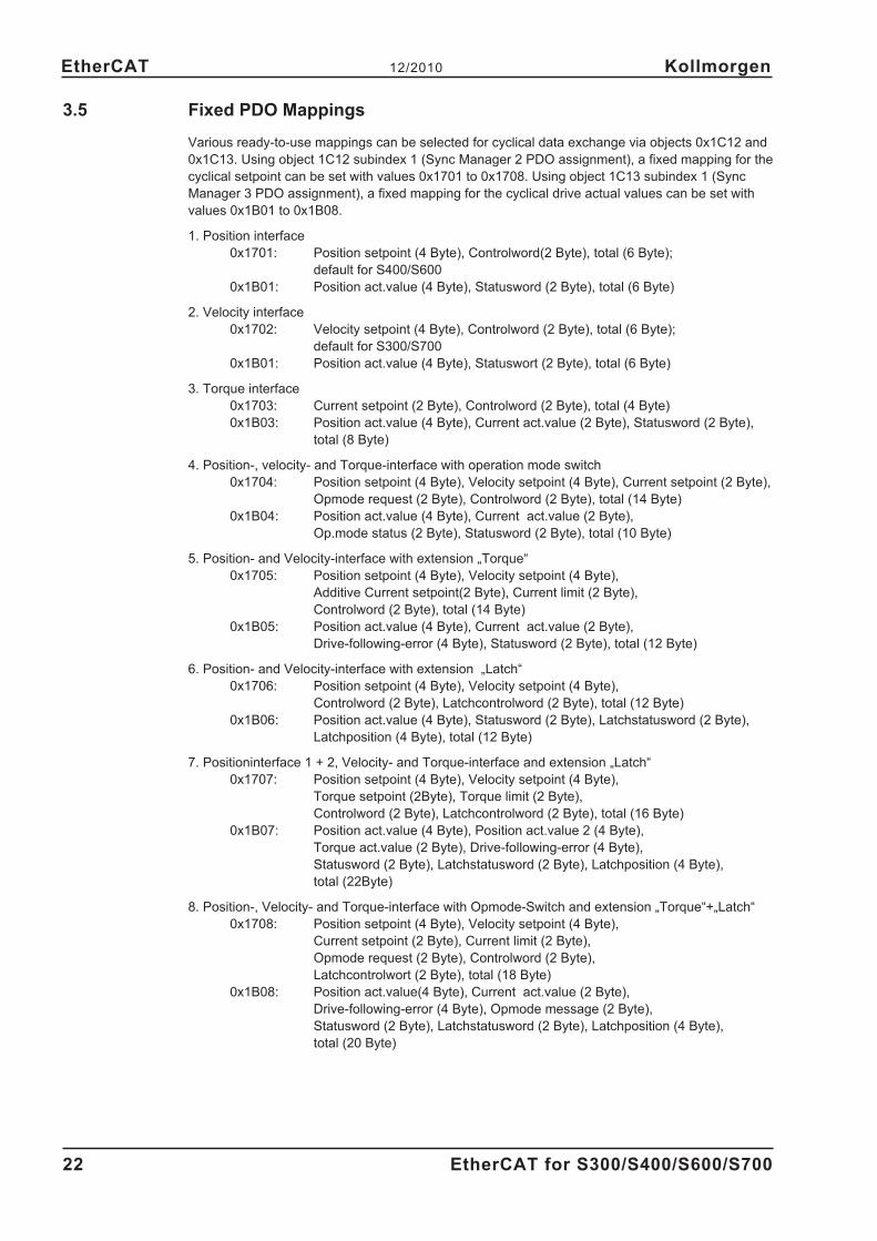
3.5 Fixed PDO Mappings
Various ready-to-use mappings can be selected for cyclical data exchange via objects 0x1C12 and
0x1C13. Using object 1C12 subindex 1 (Sync Manager 2 PDO assignment), a fixed mapping for the
cyclical setpoint can be set with values 0x1701 to 0x1708. Using object 1C13 subindex 1 (Sync
Manager 3 PDO assignment), a fixed mapping for the cyclical drive actual values can be set with
values 0x1B01 to 0x1B08.
1. Position interface
0x1701: Position setpoint (4 Byte), Controlword(2 Byte), total (6 Byte);
default for S400/S600
0x1B01: Position act.value (4 Byte), Statusword (2 Byte), total (6 Byte)
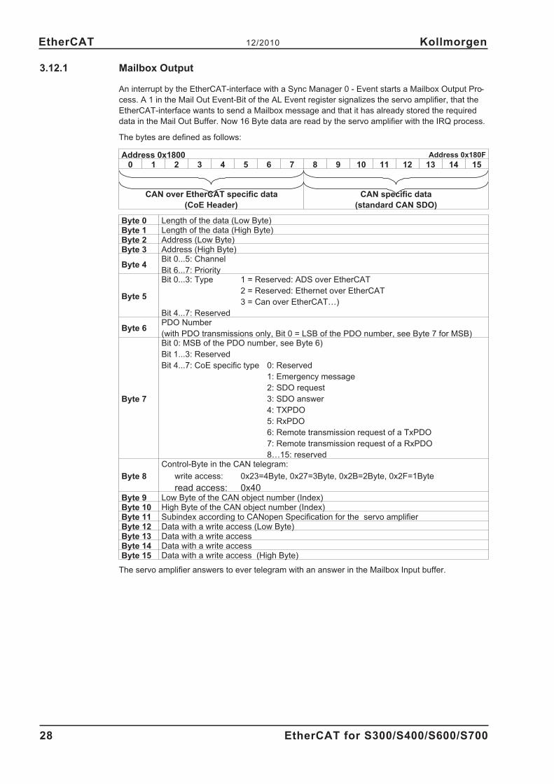
read access: 0x40Byte 9 Low Byte of the CAN object number (Index)Byte 10 High Byte of the CAN object number (Index)Byte 11 Subindex according to CANopen Specification for the servo amplifierByte 12 Data with a write access (Low Byte)Byte 13 Data with a write accessByte 14 Data with a write accessByte 15 Data with a write access (High Byte)
The servo amplifier answers to ever telegram with an answer in the Mailbox Input buffer.
28 EtherCAT for S300/S400/S600/S700
EtherCAT 12/2010 Kollmorgen
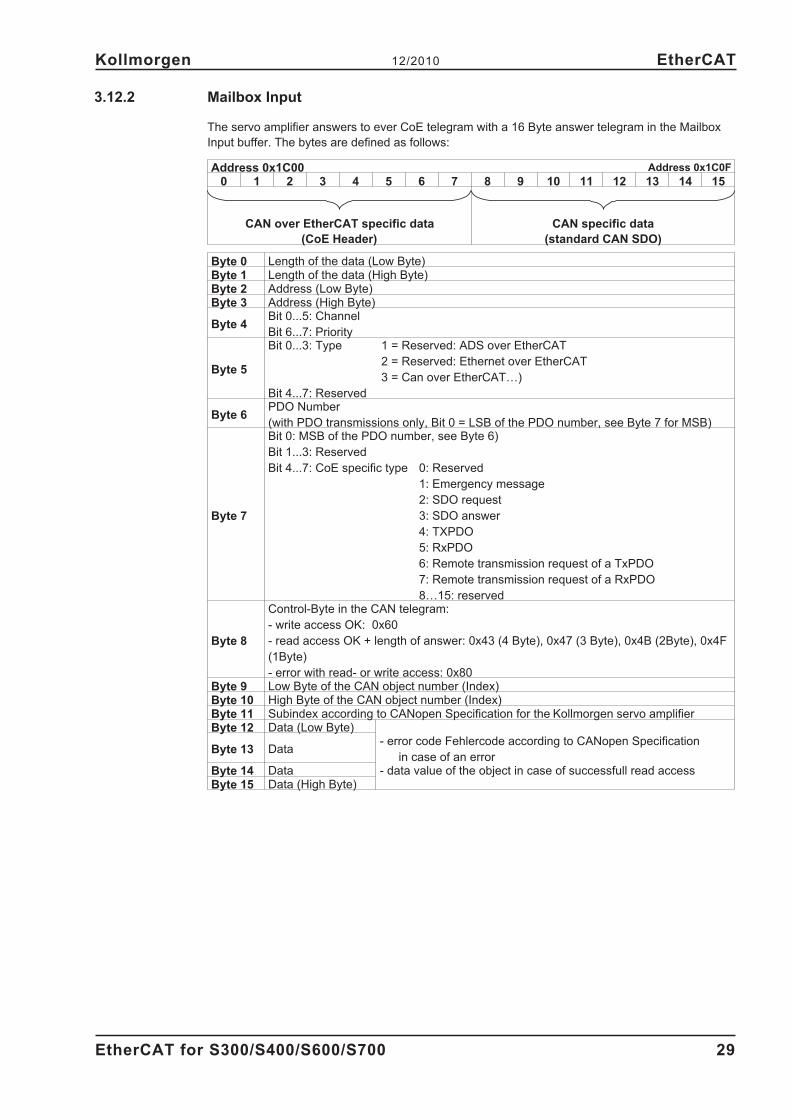
3.12.2 Mailbox Input
The servo amplifier answers to ever CoE telegram with a 16 Byte answer telegram in the Mailbox
Input buffer. The bytes are defined as follows:
Address 0x1C00 Address 0x1C0F
0 1 2 3 4 5 6 7 8 9 10 11 12 13 14 15
CAN over EtherCAT specific data
(CoE Header)
CAN specific data
(standard CAN SDO)
Byte 0 Length of the data (Low Byte)Byte 1 Length of the data (High Byte)Byte 2 Address (Low Byte)Byte 3 Address (High Byte)
Byte 4Bit 0...5: Channel
Bit 6...7: Priority
Byte 5
Bit 0...3: Type 1 = Reserved: ADS over EtherCAT
2 = Reserved: Ethernet over EtherCAT
3 = Can over EtherCAT…)
Bit 4...7: Reserved
Byte 6PDO Number
(with PDO transmissions only, Bit 0 = LSB of the PDO number, see Byte 7 for MSB)
Byte 7
Bit 0: MSB of the PDO number, see Byte 6)
Bit 1...3: Reserved
Bit 4...7: CoE specific type 0: Reserved
1: Emergency message
2: SDO request
3: SDO answer
4: TXPDO
5: RxPDO
6: Remote transmission request of a TxPDO
7: Remote transmission request of a RxPDO
8…15: reserved
Byte 8
Control-Byte in the CAN telegram:
- write access OK: 0x60
- read access OK + length of answer: 0x43 (4 Byte), 0x47 (3 Byte), 0x4B (2Byte), 0x4F
(1Byte)
- error with read- or write access: 0x80Byte 9 Low Byte of the CAN object number (Index)Byte 10 High Byte of the CAN object number (Index)Byte 11 Subindex according to CANopen Specification for the Kollmorgen servo amplifierByte 12 Data (Low Byte)
Byte 13 Data- error code Fehlercode according to CANopen Specification
in case of an errorByte 14 Data - data value of the object in case of successfull read accessByte 15 Data (High Byte)
EtherCAT for S300/S400/S600/S700 29
Kollmorgen 12/2010 EtherCAT
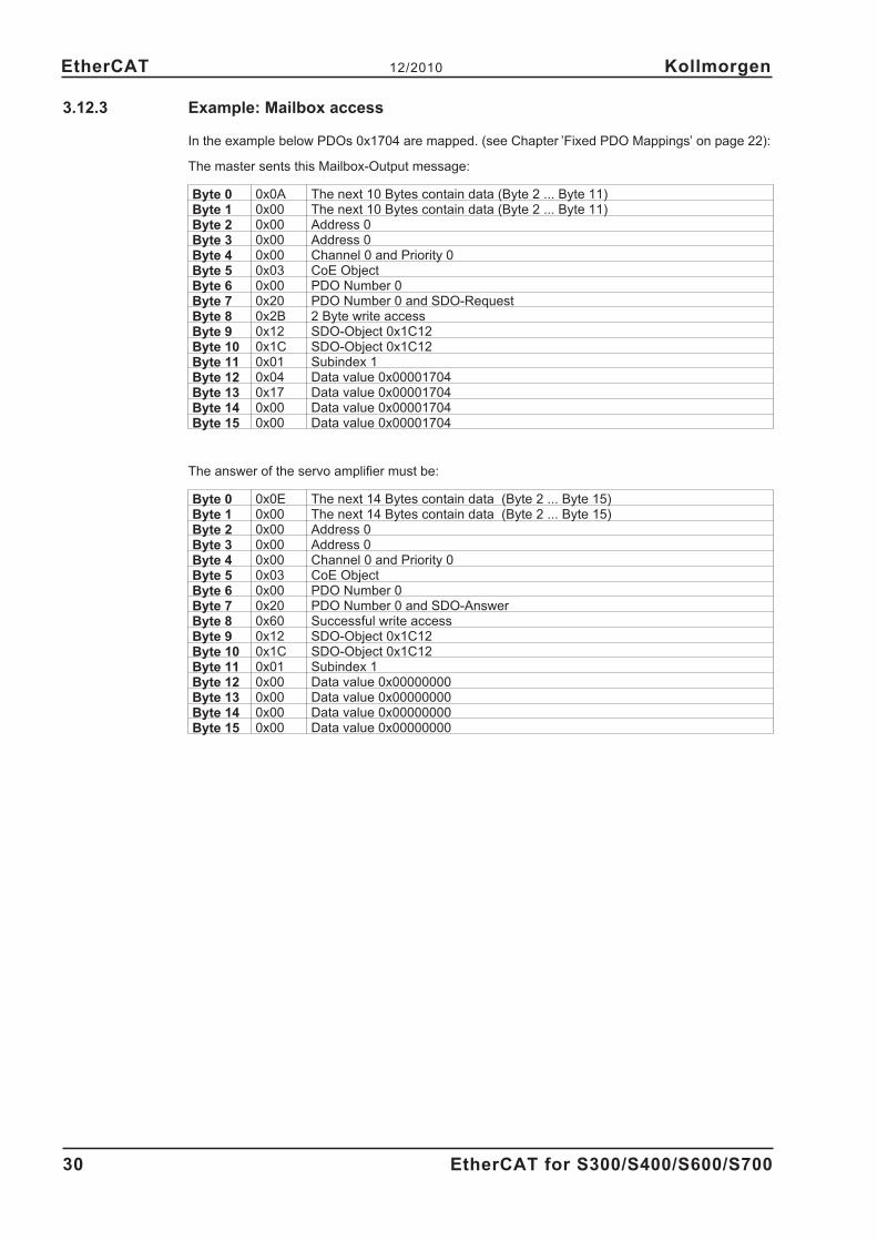
3.12.3 Example: Mailbox access
In the example below PDOs 0x1704 are mapped. (see Chapter ’Fixed PDO Mappings’ on page 22):
The master sents this Mailbox-Output message:
Byte 0 0x0A The next 10 Bytes contain data (Byte 2 ... Byte 11)Byte 1 0x00 The next 10 Bytes contain data (Byte 2 ... Byte 11)Byte 2 0x00 Address 0Byte 3 0x00 Address 0Byte 4 0x00 Channel 0 and Priority 0Byte 5 0x03 CoE ObjectByte 6 0x00 PDO Number 0Byte 7 0x20 PDO Number 0 and SDO-RequestByte 8 0x2B 2 Byte write accessByte 9 0x12 SDO-Object 0x1C12Byte 10 0x1C SDO-Object 0x1C12Byte 11 0x01 Subindex 1Byte 12 0x04 Data value 0x00001704Byte 13 0x17 Data value 0x00001704Byte 14 0x00 Data value 0x00001704Byte 15 0x00 Data value 0x00001704
The answer of the servo amplifier must be:
Byte 0 0x0E The next 14 Bytes contain data (Byte 2 ... Byte 15)Byte 1 0x00 The next 14 Bytes contain data (Byte 2 ... Byte 15)Byte 2 0x00 Address 0Byte 3 0x00 Address 0Byte 4 0x00 Channel 0 and Priority 0Byte 5 0x03 CoE ObjectByte 6 0x00 PDO Number 0Byte 7 0x20 PDO Number 0 and SDO-AnswerByte 8 0x60 Successful write accessByte 9 0x12 SDO-Object 0x1C12Byte 10 0x1C SDO-Object 0x1C12Byte 11 0x01 Subindex 1Byte 12 0x00 Data value 0x00000000Byte 13 0x00 Data value 0x00000000Byte 14 0x00 Data value 0x00000000Byte 15 0x00 Data value 0x00000000
30 EtherCAT for S300/S400/S600/S700
EtherCAT 12/2010 Kollmorgen
4 Appendix
4.1 Index
EtherCAT for S300/S400/S600/S700 31
Kollmorgen 12/2010 Appendix
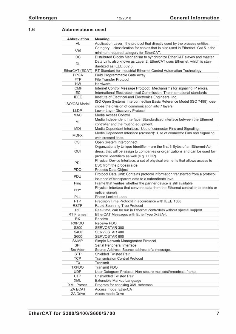
A Abbreviations. . . . . . . . . . . . . 7
AL control . . . . . . . . . . . . . . 17
AL event . . . . . . . . . . . . . . 16
AL status . . . . . . . . . . . . . . 17
AL status code . . . . . . . . . . . 17
Assembly. . . . . . . . . . . . . . . 9
C CoE . . . . . . . . . . . . . . . . . 19
Communication Phases. . . . . . . 18
Control word . . . . . . . . . . . . 20
Cycle time, adjustment . . . . . . . 25
Cycle time, suggested . . . . . . . 25
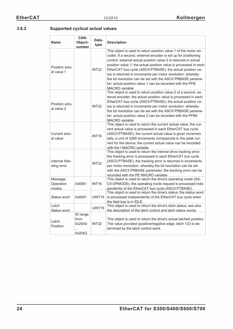
cyclical actual values . . . . . . . . 24
cyclical setpoint values . . . . . . . 23
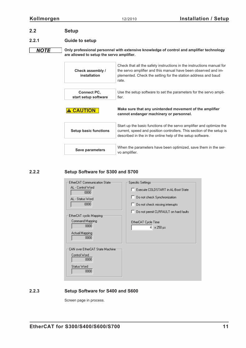
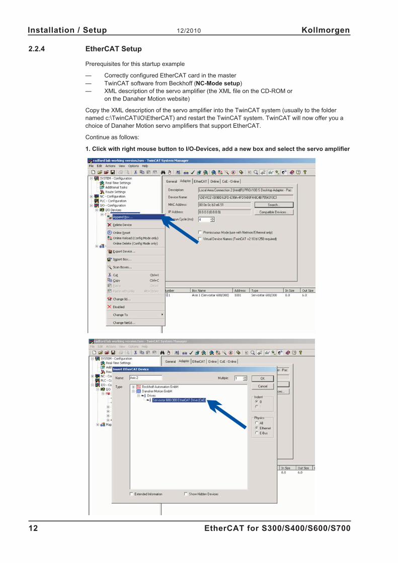
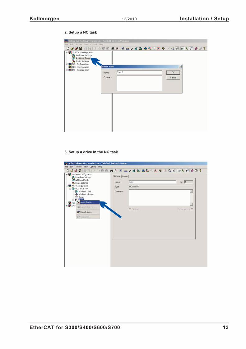
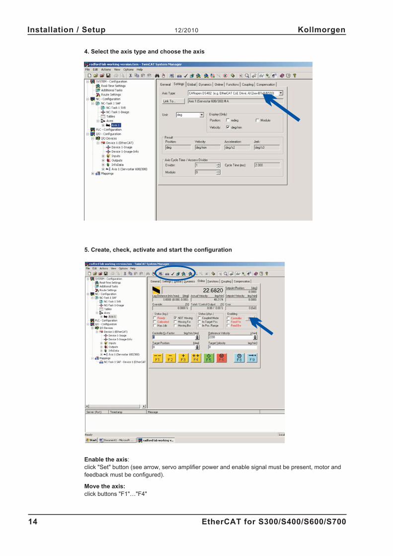
E EtherCat Setup . . . . . . . . . . . 12
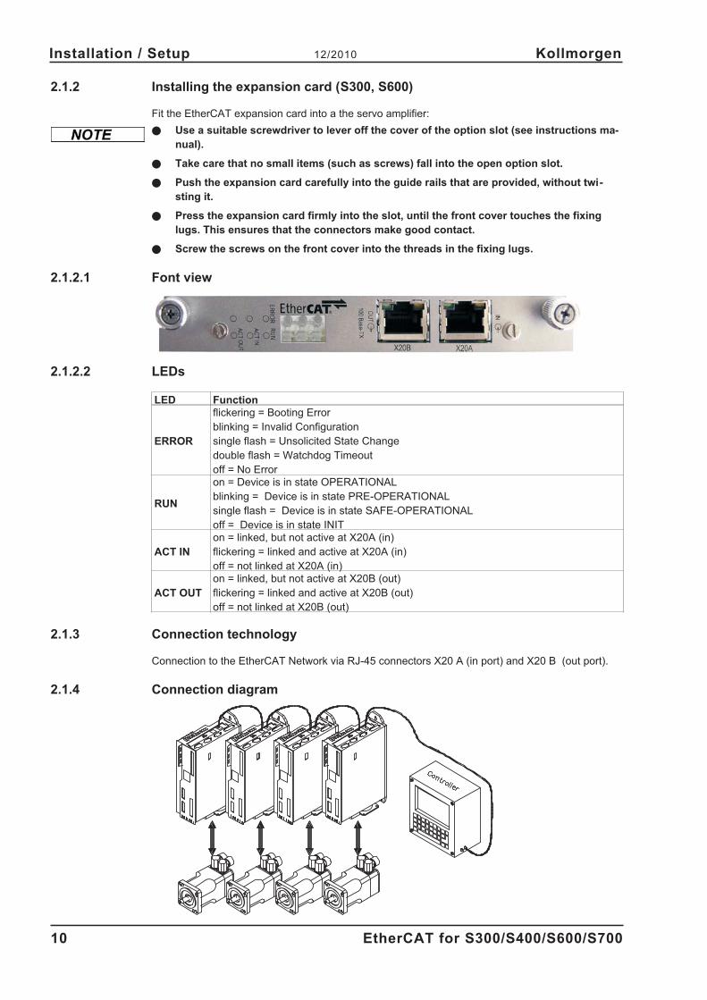
Expansion card . . . . . . . . . . . 10
I Installation . . . . . . . . . . . . . . 9
Interrupt Enable. . . . . . . . . . . 16
Interrupt Event . . . . . . . . . . . 16
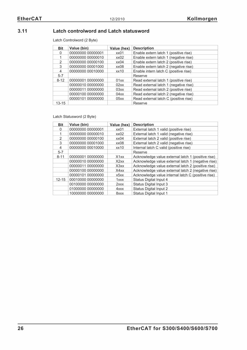
L Latch controlword . . . . . . . . . . 26
Latch statusword . . . . . . . . . . 26
M Mailbox . . . . . . . . . . . . . . . 27
O Operation modes . . . . . . . . . . 25
P PDO Mappings . . . . . . . . . . . 22
Phase run-up . . . . . . . . . . . . 17
S Setup . . . . . . . . . . . . . . . . 11
Slave Register . . . . . . . . . . . 15
Status machine . . . . . . . . . . . 21
Symbols . . . . . . . . . . . . . . . 6
Synchronization. . . . . . . . . . . 25
T Target group . . . . . . . . . . . . . 5
U Use as directed. . . . . . . . . . . . 6
Service
We are committed to quality customer service. In order to serve in the most effective way,
please contact your local sales representative for assistance.
If you are unaware of your local sales representative, please contact the Customer Support.