24
CS144, Stanford University CS144 An Introduction to Computer Networks Ethernet and CSMA/CD Nick McKeown Professor of Electrical Engineering and Computer Science, Stanford University
CS144, Stanford University
CS144An Introduction to Computer Networks
Ethernet and CSMA/CD
Nick McKeownProfessor of Electrical Engineering and Computer Science, Stanford University
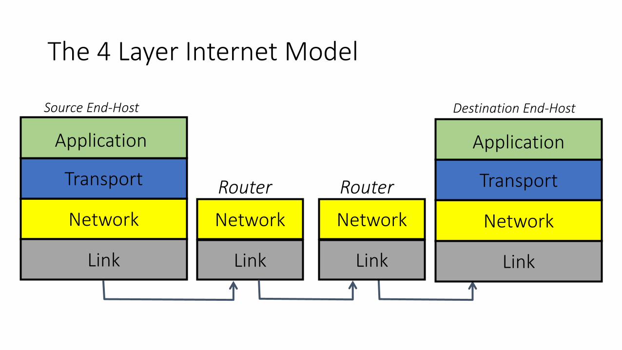
The 4 Layer Internet Model
Network
Link
Network
Link
Transport
Application
Router
Source End-Host
Network
Link
Transport
Application
Destination End-Host
Network
Link
Router
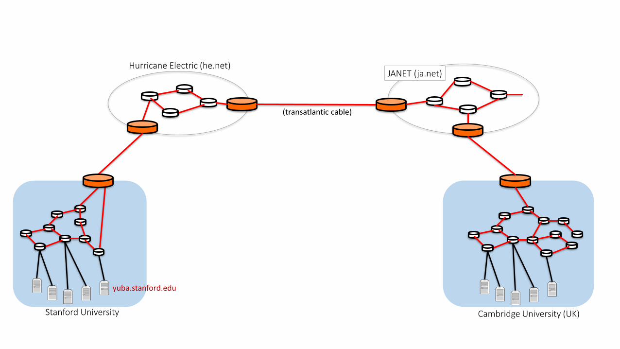
Cambridge University (UK)
Hurricane Electric (he.net)JANET (ja.net)
(transatlantic cable)
Stanford University
yuba.stanford.edu

Stanford University
yuba.stanford.edu
Ethernet switches

Ethernet switch
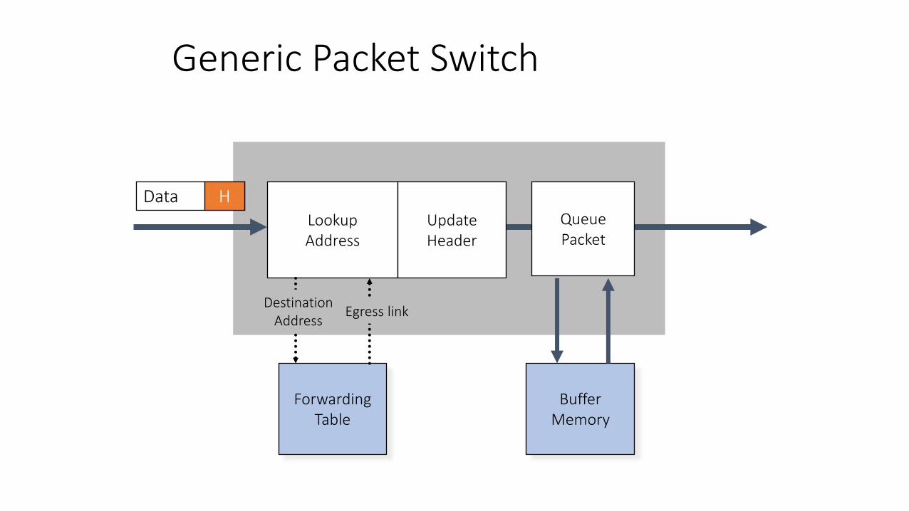
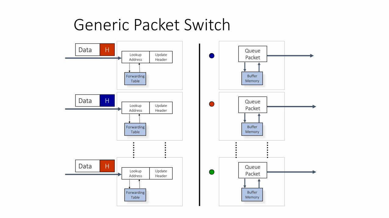
Generic Packet Switch
LookupAddress
Data H
DestinationAddress
ForwardingTable
Egress link
QueuePacket
BufferMemory
UpdateHeader
Generic Packet Switch
LookupAddress
UpdateHeader
ForwardingTable
LookupAddress
UpdateHeader
ForwardingTable
LookupAddress
UpdateHeader
ForwardingTable
QueuePacket
BufferMemory
QueuePacket
BufferMemory
QueuePacket
BufferMemory
Data H
Data H
Data H
8
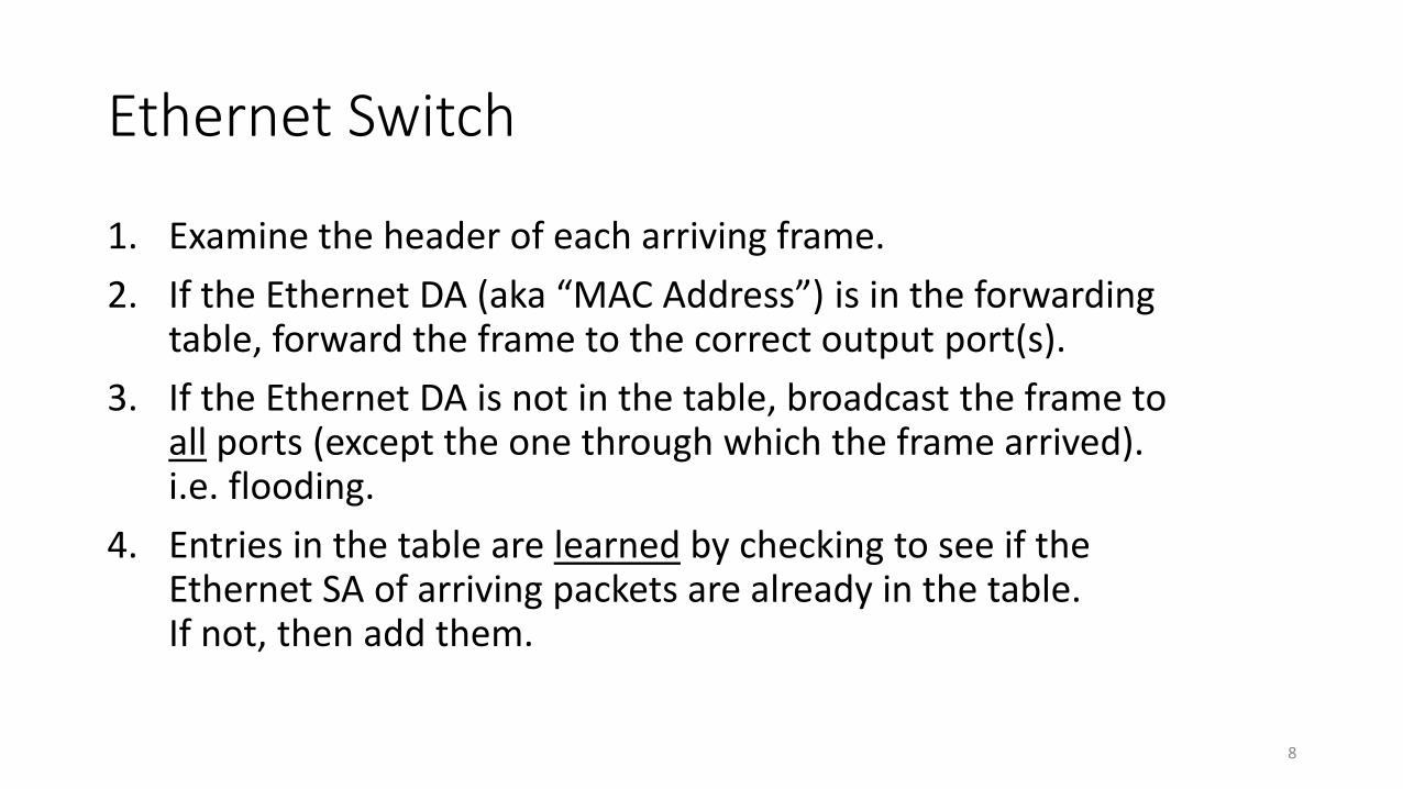
Ethernet Switch
1. Examine the header of each arriving frame.
2. If the Ethernet DA (aka “MAC Address”) is in the forwarding table, forward the frame to the correct output port(s).
3. If the Ethernet DA is not in the table, broadcast the frame to all ports (except the one through which the frame arrived). i.e. flooding.
4. Entries in the table are learned by checking to see if the Ethernet SA of arriving packets are already in the table. If not, then add them.
9
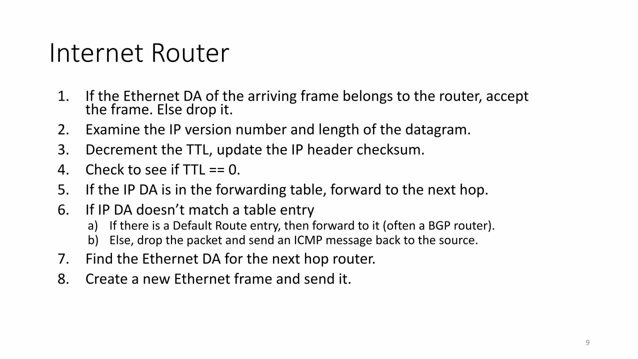
Internet Router
1. If the Ethernet DA of the arriving frame belongs to the router, accept the frame. Else drop it.
2. Examine the IP version number and length of the datagram.
3. Decrement the TTL, update the IP header checksum.
4. Check to see if TTL == 0.
5. If the IP DA is in the forwarding table, forward to the next hop.
6. If IP DA doesn’t match a table entrya) If there is a Default Route entry, then forward to it (often a BGP router).b) Else, drop the packet and send an ICMP message back to the source.
7. Find the Ethernet DA for the next hop router.
8. Create a new Ethernet frame and send it.
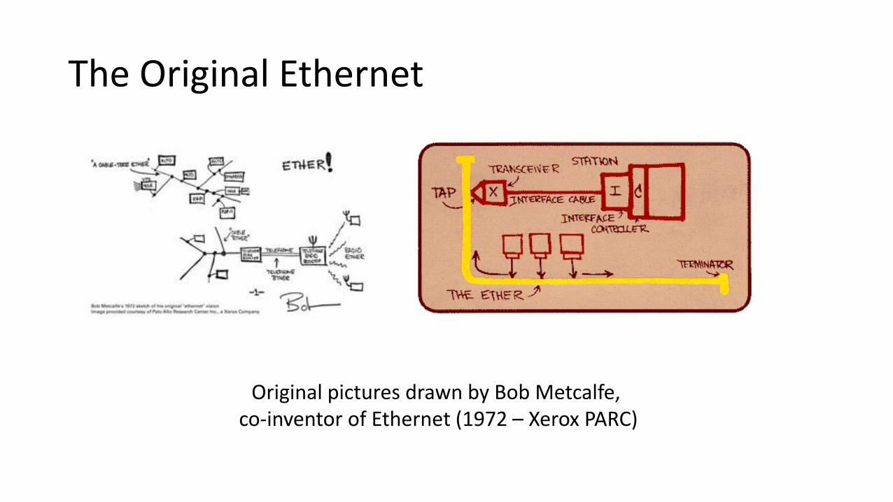
The Original Ethernet
Original pictures drawn by Bob Metcalfe, co-inventor of Ethernet (1972 – Xerox PARC)
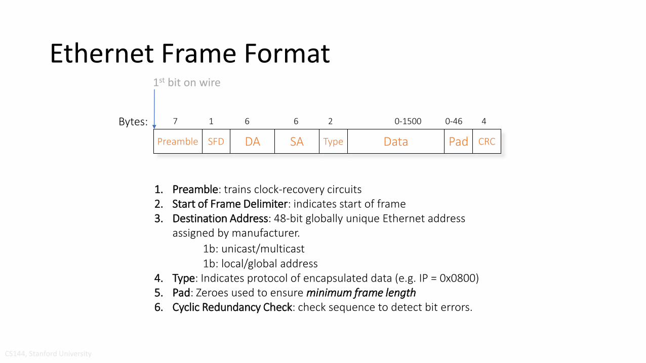
Ethernet Frame Format
Preamble SFD DA SA Type Data Pad CRC
7 1 6 6 2 0-1500 0-46 4
1. Preamble: trains clock-recovery circuits2. Start of Frame Delimiter: indicates start of frame3. Destination Address: 48-bit globally unique Ethernet address
assigned by manufacturer.
1b: unicast/multicast1b: local/global address
4. Type: Indicates protocol of encapsulated data (e.g. IP = 0x0800)5. Pad: Zeroes used to ensure minimum frame length6. Cyclic Redundancy Check: check sequence to detect bit errors.
Bytes:
CS144, Stanford University
1st bit on wire
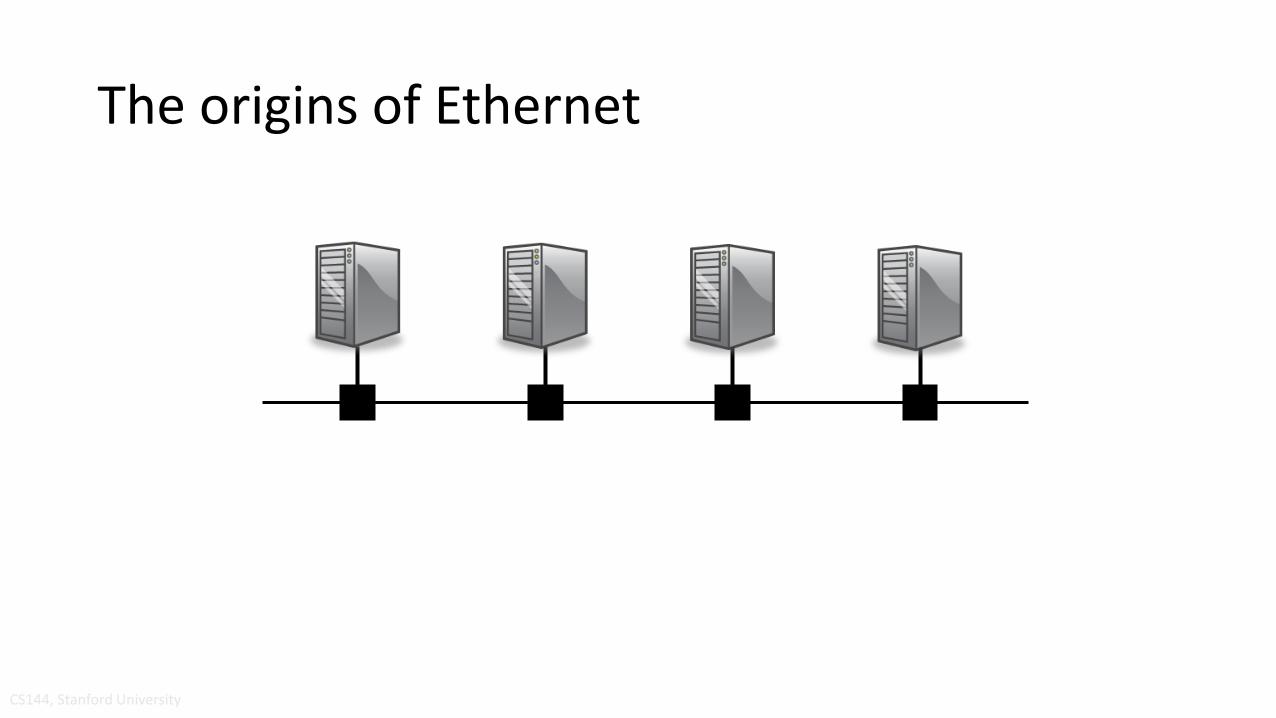
The origins of Ethernet
CS144, Stanford University
Sharing a “medium”
• Ethernet is, or at least was originally, an example of multiple hosts sharing a common cable (“medium”).
• To share the medium, we need to decide who gets to send, and when.
• There is a general class of “Medium Access Control Protocols”, or MAC Protocols. Hence the name “MAC address”.
• Ethernet uses a MAC protocol called “CSMA/CD”.
CS144, Stanford University

CSMA/CD Protocol
All hosts transmit & receive on one channelPackets are of variable size.
When a host has a packet to transmit:1. Carrier Sense: Check if the line is quiet before transmitting.2. Collision Detection: Detect collision as soon as possible.
If a collision is detected, stop transmitting; wait a random time, then return to step 1.
binary exponential backoff
CS144, Stanford University
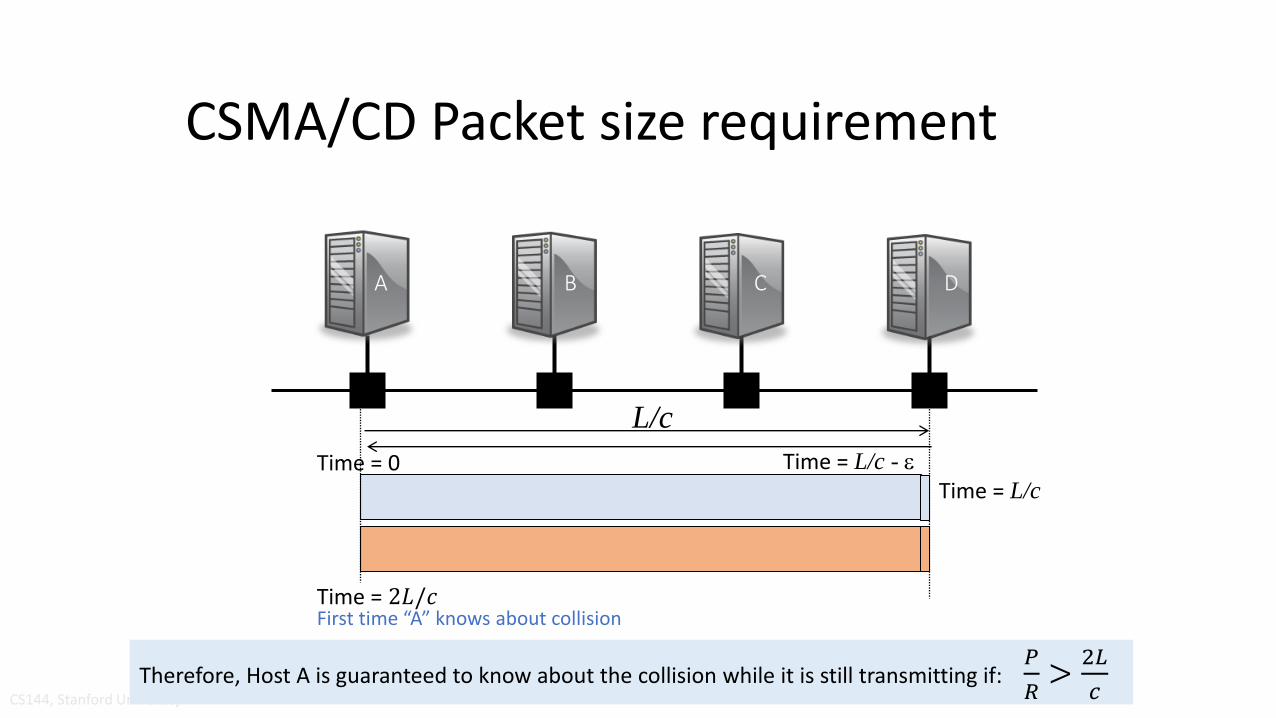
CSMA/CD Packet size requirement
CS144, Stanford University
A B C D
L/c
Time = 0 Time = L/c - e
Time = L/c
Time = 2𝐿/𝑐First time “A” knows about collision
Therefore, Host A is guaranteed to know about the collision while it is still transmitting if:𝑃
𝑅>
2𝐿
𝑐

CSMA/CD Packet size requirement
CS144, Stanford University
A B C D
L/c
For an end host to detect a collision before it finishes transmitting a packet, we require:
where P is the size of a packet.
R
𝑃
𝑅>2𝐿
𝑐
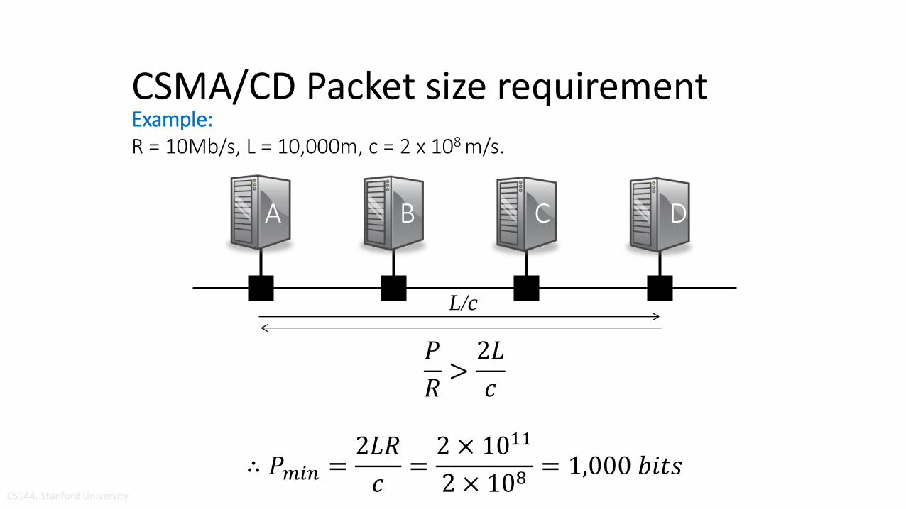
CSMA/CD Packet size requirement
CS144, Stanford University
A B C D
Example: R = 10Mb/s, L = 10,000m, c = 2 x 10⁸ m/s.
L/c
𝑃
𝑅>2𝐿
𝑐
∴ 𝑃𝑚𝑖𝑛 =2𝐿𝑅
𝑐=2 × 10¹¹
2 × 108= 1,000 𝑏𝑖𝑡𝑠
Ethernet evolution
• Early 1980s: Ethernet was a 10Mb/s shared medium. Literally a thick coaxial cable that snaked around the floor into which every computer was plugged.
• Late 1980s: Ethernet “10baseT” used the twisted-pair phone cables already installed in buildings. Used a star topology. Ethernet hubs connected end hosts together with one big collision domain.
• Early 1990s: Ethernet Switches were invented. Dedicated cable between the switch and the end host carrying packets in both directions simultaneously. No collisions any more!
• Since then: 100Mb/s Ethernet, 1GE, 10GE, 100GE, 400GE, …
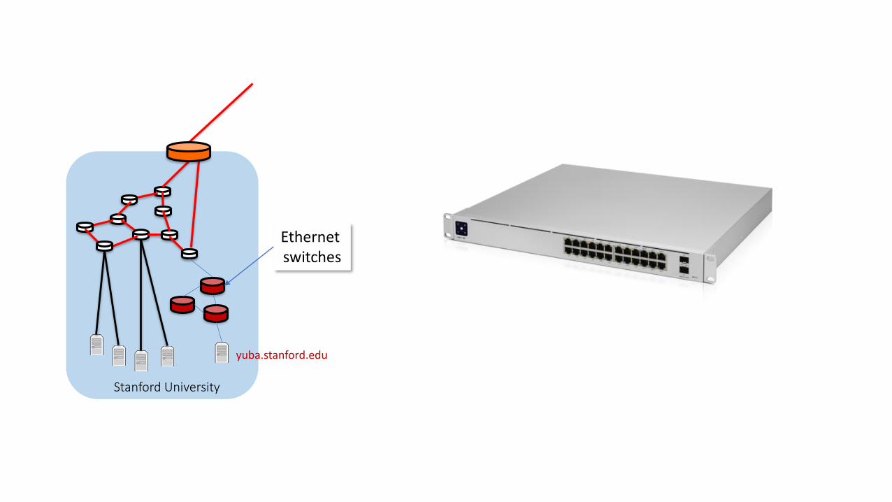
Stanford University
yuba.stanford.edu
Ethernet switches
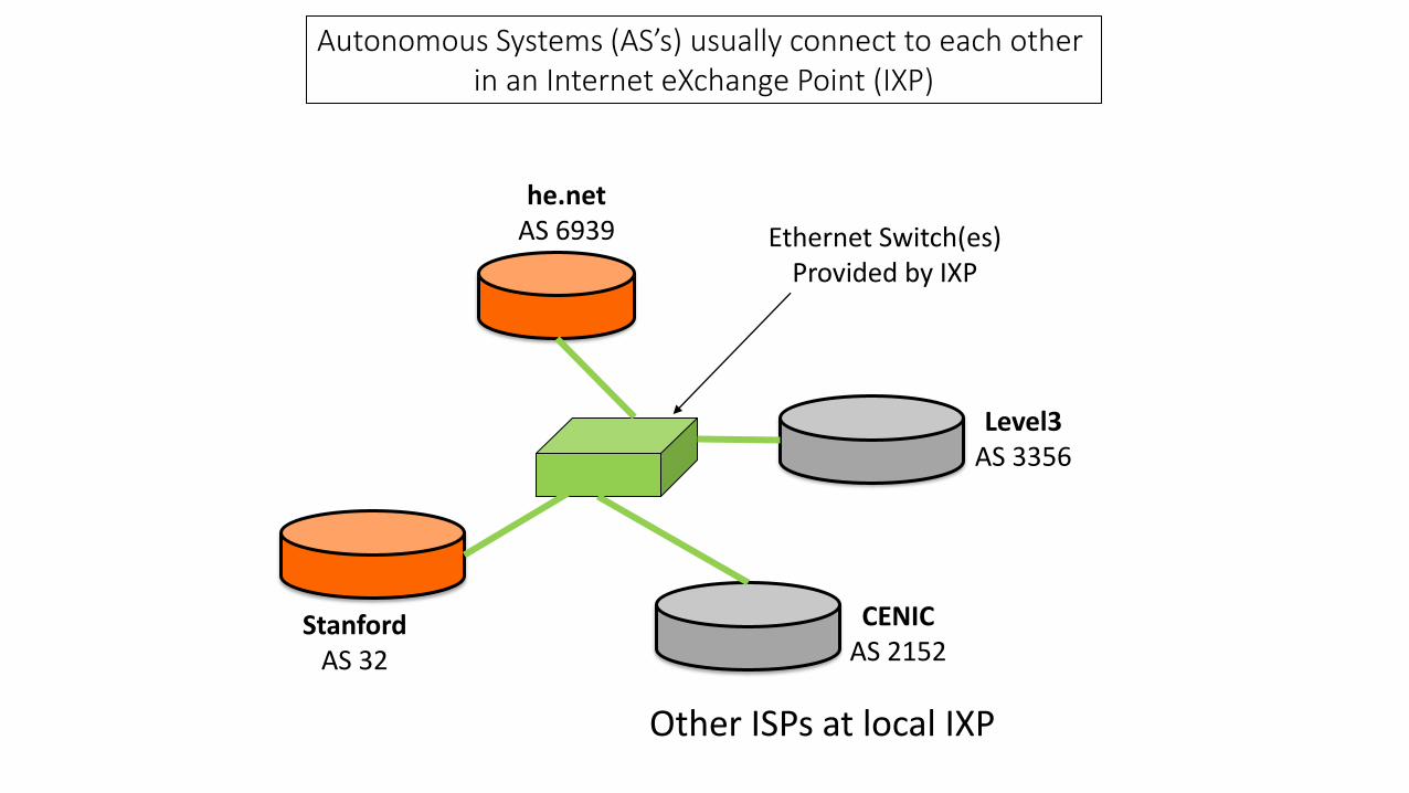
Autonomous Systems (AS’s) usually connect to each other in an Internet eXchange Point (IXP)
StanfordAS 32
he.netAS 6939
CENICAS 2152
Level3AS 3356
Other ISPs at local IXP
Ethernet Switch(es)Provided by IXP

The 4 Layer Internet Model
Network
Link
Network
Link
Transport
Application
Router
Source End-Host
Network
Link
Transport
Application
Destination End-Host
Network
Link
Router
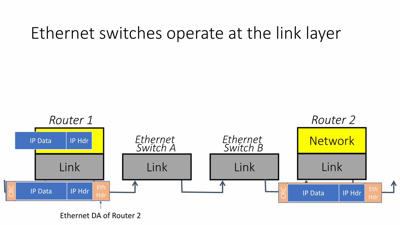
Ethernet switches operate at the link layer
Network
Link
Router 1
Network
Link
Router 2
Link Link
Ethernet Switch A
Ethernet Switch B
Eth HdrC
RC
IP Data IP Hdr
Ethernet DA of Router 2
Eth HdrC
RC
IP Data IP Hdr Eth HdrC
RC
IP Data IP Hdr
Why an IXP uses Ethernet switches…
• The IXP doesn’t need to maintain routing tables
• The IXP doesn’t need to exchange routing entries with its customers
• The IXP doesn’t need to decide how packets are routed
• It merely provides “Link Layer” connectivity among its customers.
Ethernet in use today
• Almost all enterprises and campuses use Ethernet as a simple, quick, cheap, easy-to-manage way to interconnect hosts and WiFi APs inside a building. Routers are typically use to connect buildings together.
• Data-centers typically use an Ethernet switch to connect 48-64 servers together in each rack. Called “Top of Rack” or ToRswitches. Routing is typically used to connect racks together.


![CSMA/CCA: A Modified CSMA/CA Protocol Mitigating the ...cheung/Courses/558/Syllabus/Papers/CSMA … · The medium access control (MAC) ... (MACA) protocol [3], ... MACAW [4]. The](https://static.documents.pub/doc/80x56/5b5b7a167f8b9a302a8e0f8a/csmacca-a-modified-csmaca-protocol-mitigating-the-cheungcourses558syllabuspaperscsma.jpg)


