EtherNet/IP Interface Option Unit FR-A8NEIP ENG, Version A, 19072013 Safety Information For qualified staff only This manual is only intended for use by properly trained and qualified electri- cal technicians who are fully acquainted with automation technology safety standards. All work with the hardware described, including system design, installation, setup, maintenance, service and testing, may only be performed by trained electrical technicians with approved qualifications who are fully acquainted with the applicable automation technology safety standards and regulations. Proper use of equipment The frequency inverters of the FR-A800 series are only intended for the specific applications explicitly described in this manual and the manuals listed below. Please take care to observe all the installation and operating parameters spec- ified in the manuals. Only accessories and peripherals specifically approved by MITSUBISHI ELECTRIC may be used. Any other use or application of the pro- ducts is deemed to be improper. Relevant safety regulations All safety and accident prevention regulations relevant to your specific appli- cation must be observed in the system design, installation, setup, mainte- nance, servicing and testing of these products. In this manual special warnings that are important for the proper and safe use of the products are clearly identified as follows: Further Information The following manuals contain further information about the devices: ● Instruction manual of the frequency inverter FR-A800 ● Instruction manual of the plug-in option A8NEIP_2P ● Beginner’s Guide of the frequency inverter FR-A800 ● Installation Guide of the frequency inverter FR-A800 These manuals are available free of charge through the internet: ● www.mitsubishi-automation.com (EU) ● www.MEAU.com (Americas) If you have any questions concerning the programming and operation of the equipment described in this manual, please contact your relevant sales office or department. General Description With the EtherNet/IP interface adapter, the FR-A800 series frequency inverter can be connected to an EtherNet/IP network by using an RJ45 connector. Important Information Please observe all the following warnings and information to ensure that the option unit is installed correctly. Installing Of The Plug-in Option The following operation steps describe the physical installation of the option unit. You will find a detailed description how to mount the interface option unit in the A8NEIP_2P instruction manual and the FR-A800 frequency inverter instruction manual. Unfasten the lower screws on the front of the inverter and remove the front lower cover. Remove the front top cover in the same manner. Secure board spacers to upper right and lower left corners of the option unit. Position the option unit and fasten it with the screws in the lower right and upper left corners. Please note that the option unit can only be installed in position . Install PE plate as shown in the picture below. Please note that the plate is fastened to the right with the same screw as the option unit lower right corner. Connect the EtherNet/IP cable(s) to the network connector(s) on the option unit. Cut off the hooks on the rear of the inverter front cover with a nipper etc., and remove the lid. Place the EtherNet/IP LED cover in the empty position. Reinstall the front covers, giving safe passage for the network cables. The option unit is now installed and ready for configuration. Attach power cable and supply power to configure the inverter and the option unit. Package Contents Frequency Inverters m DANGER: Personnel health and injury warnings. Failure to observe the precautions described here can result in serious health and injury hazards. b CAUTION: Equipment and property damage warnings. Failure to observe the precautions described here can result in serious damage to the equipment or other property. m DANGER ● Cut off all phases of the power source externally before starting the in- stallation or wiring work, thus avoiding electric shock or damages to the product. ● After disconnecting the power wait for at least 10 minutes before in- stalling option units to allow the power capacitors in the inverter time to discharge to a safe level. ● The inverter must be grounded with a proper earth connector con- forming to all national and local safety regulations and standards (JIS, NEC Section 250, IEC 536 Class 1 and other standards). ● Do not remove any components unless explicitly instructed to do so in this manual. Failure to observe this warning can result in damage to the inverter. b CAUTION ● Only operate the inverter and the option units within the environmen- tal parameters specified in the inverter manual. Take steps to ensure that neither the inverter nor the option units are exposed to dust, oil spray, corrosive and flammable gases, intense vibrations and physical shocks, high temperatures, condensation or damp. ● When drilling screw holes or wiring, cutting chips or wire chips should not enter ventilation slits. Such an accident may cause fire, failure or malfunction. ● Do not touch any of the inverter‘s live components, such as the connec- tion terminals or plug connectors. ● The inverter housing gets very hot during operation. To avoid burns do not touch the inverter when it is turned on and wait for a short peri- od after its power supply has been switched off before touching the housing. Printed board Spacers EtherNet/IP cables PE plate Lower right screw for fixing PE plate and option unit Hooks Hooks NOTE The EtherNet/IP Interface Option Unit FR-A8NEIP fulfils the requirements of the Common Industrial Protocol (CIP) EtherNet/IP specification. For full perfor- mance only use EtherNet/IP compliant Industrial Ethernet Cables. Item No. of pieces PCB board 1 M3 x 6 mm screw 3 Board spacer 2 LED cover 1 PE plate 1 Opening in the top front cover Placement of the EtherNet/IP LED cover Mitsubishi Electric Europe B.V. /// FA - European Business Group /// Germany /// Tel.: +49(0)2102-4860 /// Fax: +49(0)2102-4861120 /// www.mitsubishi-automation.com MITSUBISHI ELECTRIC AUTOMATION, Inc. /// FA - Americas /// USA /// Phone: +1 (847) 478-2100 /// Fax: +1 (847) 478-0328 /// www.MEAU.com
Transcript
EtherNet/IP Interface Option UnitFR-A8NEIP
ENG, Version A, 19072013
Safety Information
For qualified staff onlyThis manual is only intended for use by properly trained and qualified electri-cal technicians who are fully acquainted with automation technology safetystandards. All work with the hardware described, including system design,installation, setup, maintenance, service and testing, may only be performedby trained electrical technicians with approved qualifications who are fullyacquainted with the applicable automation technology safety standards andregulations.
Proper use of equipmentThe frequency inverters of the FR-A800 series are only intended for the specificapplications explicitly described in this manual and the manuals listed below.Please take care to observe all the installation and operating parameters spec-ified in the manuals. Only accessories and peripherals specifically approved byMITSUBISHI ELECTRIC may be used. Any other use or application of the pro-ducts is deemed to be improper.
Relevant safety regulationsAll safety and accident prevention regulations relevant to your specific appli-cation must be observed in the system design, installation, setup, mainte-nance, servicing and testing of these products. In this manual special warnings that are important for the proper and safe useof the products are clearly identified as follows:
Further InformationThe following manuals contain further information about the devices:● Instruction manual of the frequency inverter FR-A800● Instruction manual of the plug-in option A8NEIP_2P● Beginner’s Guide of the frequency inverter FR-A800● Installation Guide of the frequency inverter FR-A800
These manuals are available free of charge through the internet:● www.mitsubishi-automation.com (EU)● www.MEAU.com (Americas)
If you have any questions concerning the programming and operation of theequipment described in this manual, please contact your relevant sales officeor department.
General DescriptionWith the EtherNet/IP interface adapter, the FR-A800 series frequency invertercan be connected to an EtherNet/IP network by using an RJ45 connector.
Important InformationPlease observe all the following warnings and information to ensure that theoption unit is installed correctly.
Installing Of The Plug-in OptionThe following operation steps describe the physical installation of the optionunit. You will find a detailed description how to mount the interface optionunit in the A8NEIP_2P instruction manual and the FR-A800 frequency inverterinstruction manual.� Unfasten the lower screws on the front of the inverter and remove the front
lower cover.� Remove the front top cover in the same manner.� Secure board spacers to upper right and lower left corners of the option
unit.
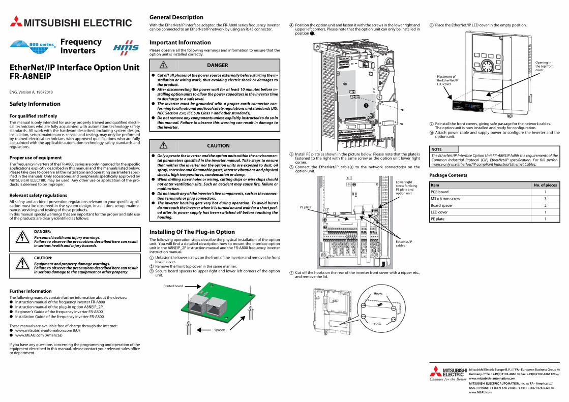
� Position the option unit and fasten it with the screws in the lower right andupper left corners. Please note that the option unit can only be installed inposition �.
� Install PE plate as shown in the picture below. Please note that the plate isfastened to the right with the same screw as the option unit lower rightcorner.
� Connect the EtherNet/IP cable(s) to the network connector(s) on theoption unit.
Cut off the hooks on the rear of the inverter front cover with a nipper etc.,and remove the lid.
Place the EtherNet/IP LED cover in the empty position.
� Reinstall the front covers, giving safe passage for the network cables.The option unit is now installed and ready for configuration.
� Attach power cable and supply power to configure the inverter and theoption unit.
Package Contents
FrequencyInverters
mDANGER:
Personnel health and injury warnings.Failure to observe the precautions described here can resultin serious health and injury hazards.
bCAUTION:
Equipment and property damage warnings.Failure to observe the precautions described here can resultin serious damage to the equipment or other property.
m DANGER
● Cut off all phases of the power source externally before starting the in-stallation or wiring work, thus avoiding electric shock or damages tothe product.
● After disconnecting the power wait for at least 10 minutes before in-stalling option units to allow the power capacitors in the inverter timeto discharge to a safe level.
● The inverter must be grounded with a proper earth connector con-forming to all national and local safety regulations and standards (JIS,NEC Section 250, IEC 536 Class 1 and other standards).
● Do not remove any components unless explicitly instructed to do so inthis manual. Failure to observe this warning can result in damage tothe inverter.
b CAUTION
● Only operate the inverter and the option units within the environmen-tal parameters specified in the inverter manual. Take steps to ensurethat neither the inverter nor the option units are exposed to dust, oilspray, corrosive and flammable gases, intense vibrations and physicalshocks, high temperatures, condensation or damp.
● When drilling screw holes or wiring, cutting chips or wire chips shouldnot enter ventilation slits. Such an accident may cause fire, failure ormalfunction.
● Do not touch any of the inverter‘s live components, such as the connec-tion terminals or plug connectors.
● The inverter housing gets very hot during operation. To avoid burnsdo not touch the inverter when it is turned on and wait for a short peri-od after its power supply has been switched off before touching thehousing.
Printed board
Spacers
�
EtherNet/IP cables
PE plate
Lower right screw for fixing PE plate and option unit
Hooks
Hooks
NOTE
The EtherNet/IP Interface Option Unit FR-A8NEIP fulfils the requirements of theCommon Industrial Protocol (CIP) EtherNet/IP specification. For full perfor-mance only use EtherNet/IP compliant Industrial Ethernet Cables.
Item No. of pieces
PCB board 1
M3 x 6 mm screw 3
Board spacer 2
LED cover 1
PE plate 1
Opening in the top front cover
Placement of the EtherNet/IP LED cover
Mitsubishi Electric Europe B.V. /// FA - European Business Group ///Germany /// Tel.: +49(0)2102-4860 /// Fax: +49(0)2102-4861120 /// www.mitsubishi-automation.com
MITSUBISHI ELECTRIC AUTOMATION, Inc. /// FA - Americas /// USA /// Phone: +1 (847) 478-2100 /// Fax: +1 (847) 478-0328 ///www.MEAU.com
EtherNet/IP-SchnittstelleOptionseinheit FR-A8NEIP
GER, Version A, 19072013
Sicherheitshinweise
Nur für qualifizierte ElektrofachkräfteDiese Installationsanleitung richtet sich ausschließlich an anerkannt ausgebil-dete Elektrofachkräfte, die mit den Sicherheitsstandards der Automatisie-rungstechnik vertraut sind. Projektierung, Installation, Inbetriebnahme,Wartung und Prüfung der Geräte dürfen nur von einer anerkannt ausgebilde-ten Elektrofachkraft, die mit den Sicherheitsstandards der Automatisierungs-technik vertraut ist, durchgeführt werden.
Bestimmungsgemäßer GebrauchDie Frequenzumrichter der Serie FR-A800 sind nur für die Einsatzbereiche vor-gesehen, die in der vorliegenden Installationsanleitung oder den unten aufge-führten Handbüchern beschrieben sind. Achten Sie auf die Einhaltung aller inden Handbüchern angegebenen Kenndaten. Es dürfen nur von MITSUBISHIELECTRIC empfohlene Zusatz- bzw. Erweiterungsgeräte verwendet werden.Jede andere darüber hinausgehende Verwendung oder Benutzung gilt alsnicht bestimmungsgemäß.
Sicherheitsrelevante VorschriftenBei der Projektierung, Installation, Inbetriebnahme, Wartung und Prüfung derGeräte müssen die für den spezifischen Einsatzfall gültigen Sicherheits- undUnfallverhütungsvorschriften beachtet werden.In dieser Installationsanleitung befinden sich Hinweise, die für den sachge-rechten und sicheren Umgang mit dem Gerät wichtig sind. Die einzelnen Hin-weise haben folgende Bedeutung:
Weitere InformationenDie folgenden Handbücher enthalten weitere Informationen zu den Geräten:● Bedienungsanleitung zum Frequenzumrichter FR-A800● Bedienungsanleitung zu der Optionseinheit A8NEIP_2P● Einsteigerhandbuch zum Frequenzumrichter FR-A800● Installationsbeschreibung zum Frequenzumrichter FR-A800
Diese Handbücher stehen Ihnen im Internet kostenlos zur Verfügung:● www.mitsubishi-automation.com (EU)● www.MEAU.com (Nord-, Mittel- und Südamerika)
Sollten sich Fragen bezüglich Installation und Betrieb der in dieser Installati-onsanleitung beschriebenen Geräte ergeben, zögern Sie nicht, Ihr zuständigesVerkaufsbüro oder einen Ihrer Vertriebspartner zu kontaktieren.
Allgemeine BeschreibungNach Einbau des EtherNet/IP-Schnittstellenadapters können die Frequenzum-richter der Serie FR-A800 über den RJ45-Anschluss mit dem EtherNet/IP-Netz-werk verbunden werden.
InstallationshinweiseBitte beachten Sie die folgenden Installationshinweise, um sicherzustellen,dass die Option korrekt eingesetzt wird.
Einbau der OptionseinheitDie folgenden Schritte beschreiben die Vorgehensweise zum physikalischenEinbau der Optionseinheit. Eine detaillierte Montaganleitung finden Sie in derBedienungsanleitung der Optionseinheit A8NEIP_2P und des Frequenzum-richters FR-A800.� Lösen Sie die Schrauben an der Frontseite des Frequenzumrichters und
entfernen Sie die untere Frontabdeckung.� Entfernen Sie die obere Frontabdeckung in der gleichen Weise.� Befestigen Sie die Abstandhalter für die Printplatte in den Bohrungen an
der oberen rechten und unteren linken Ecke der Optionseinheit.
� Setzen Sie die Optionseinheit ein und befestigen Sie diese an der unterenrechten und oberen linken Ecke mit den Schrauben. Beachten Sie, dassdiese Optionseinheit nur auf der Position � montiert werden kann.
� Befestigen Sie die Erdungsschiene (PE), wie in der unteren Abbildung dar-gestellt. Beachten Sie, dass die rechte Seite der Schiene zusammen mit derunteren rechten Ecke der Optionseinheit befestigt wird.
� Stecken Sie das (die) EtherNet/IP-Kabel in die Anschlussbuchse(n) der Opti-onseinheit ein.
Durchtrennen Sie die Haltenasen auf der Innenseite der Frequenzumrich-terfrontabdeckung mit einer Zange o. Ä. und entfernen Sie die Abdeckungdes Frontausschnitts.
Setzen Sie die EtherNet/IP-LED-Frontblende in den offenen Ausschnitt ein.
� Bringen Sie die Frontabdeckungen wieder an und achten Sie auf eine ord-nungsgemäße Kabelführung. Die Optionseinheit ist nun montiert undkann konfiguriert werden.
� Stellen Sie alle Verbindungen zur Spannungsversorgung wieder her, umFrequenzumrichter und Optionseinheit zu konfigurieren.
Verpackungsinhalt
Frequenz-umrichter
mGEFAHR:
Warnung vor einer Gefährdung des AnwendersNichtbeachtung der angegebenen Vorsichtsmaßnahmenkann zu einer Gefahr für das Leben oder die Gesundheit desAnwenders führen.
bACHTUNG:
Warnung vor einer Gefährdung von GerätenNichtbeachtung der angegebenen Vorsichtsmaßnahmenkann zu schweren Schäden am Gerät oder anderen Sachwer-ten führen.
m GEFAHR
● Schalten Sie vor der Installation die Versorgungsspannung des Fre-quenzumrichters und andere externe Spannungen aus.
● Bevor Sie mit der Installation beginnen, halten Sie eine Wartezeit vonmindestens 10 Minuten ein, damit sich die Kondensatoren nach demAbschalten der Netzspannung auf einen ungefährlichen Spannungs-wert entladen können.
● Der Frequenzumrichter muss geerdet werden. Die Erdung muss dennationalen und lokalen Sicherheitsbestimmungen und Richtlinien fol-gen (JIS, NEC Abschnitt 250, IEC 536 Klasse 1 und andere Standards).
● Deinstallieren Sie keine Teile, deren Deinstallation nicht in dieser An-leitung beschrieben ist. Andernfalls kann der Frequenzumrichter be-schädigt werden.
b ACHTUNG
● Betreiben Sie den Frequenzumrichter und die Optionseinheit nur unterden Umgebungsbedingungen, die in der Bedienungsanleitung desFrequenzumrichters aufgeführt sind. Der Frequenzumrichter und dieOptionseinheit dürfen keinem Staub, Ölnebel, keinen ätzenden oderentzündlichen Gasen, starken Vibrationen oder Schlägen, hohen Tem-peraturen und keiner Kondensation oder Feuchtigkeit ausgesetztwerden.
● Achten Sie bei der Montage darauf, dass keine Bohrspäne oder Draht-reste durch die Lüftungsschlitze in den Frequenzumrichter gelangenund so einen Kurzschluss verursachen können.
● Berühren Sie keine spannungsführenden Teile des Frequenzumrich-ters, wie z. B. die Anschlussklemmen oder Steckverbindungen.
● Berühren Sie den Frequenzumrichter weder wenn er eingeschaltet istnoch kurz nach dem Ausschalten der Spannungsversorgung. DieOberfläche kann sehr heiß sein und es besteht Verbrennungsgefahr.
Printplatte
Abstandhalter
�
EtherNet/IP- Kabel
Erdungs-schiene
Untere rechte Schraube zur Befestigung von Erdungs-schiene und Printplatte
Haltenasen
Haltenasen
HINWEIS
Die EtherNet/IP-Schnittstellenoptionseinheit FR-A8NEIP erfüllt die Anforderun-gen der CIP- (Common Industrial Protocol) und der EtherNet/IP-Spezifikation.Zum Erreichen der vollen Leistungsfähigkeit sollten nur Ethernet-Kabel fürindustriellen Einsatz verwendet werden, die für EtherNet/IP zertifiziert sind.
Teil Stückzahl
Printplatte 1
Schraube M3 x 6 mm 3
Abstandhalter für Printplatte 2
LED-Frontblende 1
Erdungsschiene 1
Ausschnitt in der oberen Frontab-deckung
Einsetzen der EtherNet/IP-LED-Frontblende
Mitsubishi Electric Europe B.V. /// FA - European Business Group ///Germany /// Tel.: +49(0)2102-4860 /// Fax: +49(0)2102-4861120 /// www.mitsubishi-automation.com
MITSUBISHI ELECTRIC AUTOMATION, Inc. /// FA - Americas /// USA /// Phone: +1 (847) 478-2100 /// Fax: +1 (847) 478-0328 ///www.MEAU.com
Interface EtherNet/IP Unité optionnelle FR-A8NEIP
FRA, Version A, 19072013
Informations de sécurité
Groupe cibleCe manuel est destiné uniquement à des électriciens qualifiés et ayant reçusune formation reconnue par l'état et qui se sont familiarisés avec les standardsde sécurité de la technique d'automatisation. Tout travail avec le matérieldécrit, y compris la planification, l'installation, la configuration, la mainte-nance, l'entretien et les tests doivent être réalisés uniquement par des électri-ciens formés et qui se sont familiarisés avec les standards et prescriptions desécurité de la technique d'automatisation applicable.
Utilisation correcteLes variateurs de fréquence de la série FR-A800 ont été conçus pour une utili-sation dans les secteurs mentionnés dans le présent manuel d'installation oudans les manuels indiqués ci-dessous. Toutes les données caractéristiquesindiquées dans les manuels doivent être respectées. Seuls les appareils auxi-liaires et d’extension recommandés par MITSUBISHI ELECTRIC doivent être uti-lisés. Tout autre usage sera considéré comme non conforme.
Prescriptions de sécurité importantesToutes les prescriptions de sécurité et de prévention d'accident importantespour votre application spécifique doivent être respectées lors de la planifica-tion, l'installation, la configuration, la maintenance, l'entretien et les tests deces produits.Dans ce manuel, les avertissements spéciaux importants pour l'utilisation cor-recte et sûre des produits sont indentifiés clairement comme suit :
Autres informationsLes manuels suivants comportent d'autres informations sur les modules :● Manuel d'utilisation du variateur de fréquence FR-A800● Manuel d'utilisation de l'unité optionnelle A8NEIP_2P● Guide de prise en main du variateur de fréquence FR-A800● Notice d'installation du variateur de fréquence FR-A800
Ces manuels sont disponibles gratuitement sur :● www.mitsubishi-automation.com (EU)● www.MEAU.com (Americas)
Si vous avez des questions concernant la programmation et le fonctionne-ment du matériel décrit dans ce manuel, contactez votre bureau de vente res-ponsable ou votre distributeur.
Description généraleL'adaptateur d'interface EtherNet/IP permet aux variateurs de fréquence de lasérie FR-A800 de se connecter au réseau EtherNet/IP via le port RJ45.
Informations d’installationVeuillez respecter les informations d’installation suivantes afin de garantir uneimplantation correcte du module optionnel.
Montage du module optionnelLes étapes suivantes décrivent le montage de l'unité optionnelle. Vous trouvezune notice détaillée pour le montage dans le manuel d'utilisation de l'unitéoptionnelle A8NEIP_2P ainsi que dans celui du variateur de fréquence FR-A800.� Desserrez les vis sur la face avant du variateur de fréquence puis retirez le
couvercle inférieur.� Retirez le couvercle supérieur de la même manière.� Fixez l'entretoise pour la carte dans les perçages en haut à droite et en bas
à gauche de l'unité optionnelle.
� Placez l'unité optionnelle puis fixez celleci en bas à droite et en haut á gaucheavec les vis. Notez que l'unité optionnelle ne se monte qu'à la position �.
� Fixez le rail de mise à la terre (PE) comme illustré dans le schéma cidessous.Assurezvous que le côté droit du rail est bien fixé avec le coin inférieur basde l'unité optionnelle.
� Raccordez le(s) câble(s) EtherNet/IP dans la/les prise(s) de l'unité optionnelle.
Détachez les crochets à l'arrière de la face intérieure du variateur à l'aided'une pince, puis retirez le couvercle.
Placez la LED EtherNet/IP dans le logement vide.
� Remettez les couvercles avant en vous assurant du bon passage des câbles.L'unité optionnelle est montée et vous pouvez la configurer.
� Raccordez tous les câbles pour l'alimentation électrique afin de configurerle variateur de fréquence et l'unité optionnelle.
Contenu de l'emballage
Variateurde fréquence
PDANGER :
Avertissements de dommage corporel.Le non-respect des précautions décrites ici peut entraînerdes dommages corporels et des risques de blessure.
EATTENTION :
Avertissements d'endommagement du matériel et desbiens. Le non-respect des précautions décrites ici peutentraîner de graves endommagements du matériel oud'autres biens.
P DANGER
● Coupez toutes les phases de l’alimentation externe avant l’installa-tion ou le câblage pour éviter tout risque d’électrocution et toute dété-rioration du produit.
● Avant de commencer l’installation, respectez un temps d’attente d’aumoins 10 minutes afin que les condensateurs puissent se déchargerà une tension non dangereuse après la mise hors circuit de la tensiondu secteur.
● Le variateur de fréquence doit être mis à la terre. La mise à la terre doitrépondre aux prescriptions nationales et locales de sécurité ainsiqu’aux directives (JIS, NEC paragraphe 250, CEI 536 classe 1 et autresnormes).
● Ne désinstallez aucune pièce dont la désinstallation n’est pas décritedans ce manuel. Sinon, le variateur de fréquence peut être endommagé.
E ATTENTION
● Utilisez le variateur de fréquence et le module optionnel uniquementsous les conditions environnantes mentionnées dans le manuel d’uti-lisation du variateur de fréquence. Ne pas exposer le variateur de fré-quence et le module optionnel à la poussière, au brouillard d’huile,aux gaz corrosifs ou inflammables, aux fortes vibrations ou chocs, auxtempératures élevées, à la condensation ou à l’humidité.
● Faites attention lors du montage à ce qu'aucun copeau de forage oureste de câble ne pénètre dans les fentes d'aération, cela pourrait si-non provoquer un court-circuit.
● Ne touchez pas les pièces sous tension du variateur de fréquencecomme par ex. les bornes ou les fiches de raccordement.
● Ne touchez pas le variateur de fréquence, que ce soit lorsqu’il est enmarche ou peu de temps après la mise hors circuit de l’alimentation encourant. La surface peut être brûlante et présente un risque de brûlure.
Circuit imprimé
Entretoise
�
Câbles EtherNet/IP
Rail PE
Vis inférieure basse pour fixer le rail PE et le cir-cuit imprimé.
Crochets
Crochets
REMARQUE
L'unité optionnelle FR-A8NEIP pour l'interface EtherNet/IP est conforme aux exi-gences du CIP (Common Industrial Protocol) et de la spécification EtherNet/IP.Pour une performance maximale, utilisez uniquement des câbles compatiblesavec le réseau Ether-Net/IP.
Pièce Quantité
Circuit imprimé 1
Vis M3 x 6 mm 3
Entretoise pour le circuit imprimé 2
Couvercle de la LED 1
Rail PE 1
Logement dans le cou-vercle avant
Remettez le cou-vercle de la LED PROFINET
Mitsubishi Electric Europe B.V. /// FA - European Business Group ///Germany /// Tel.: +49(0)2102-4860 /// Fax: +49(0)2102-4861120 /// www.mitsubishi-automation.com
MITSUBISHI ELECTRIC AUTOMATION, Inc. /// FA - Americas /// USA /// Phone: +1 (847) 478-2100 /// Fax: +1 (847) 478-0328 ///www.MEAU.com