86
Machine Automation Controller NJ-series EtherNet/IP TM Connection Guide OMRON Corporation CJ2-series Controller P568-E1-01

Machine Automation Control ler NJ-series
EtherNet/IPT M Connection Guide
OMRON CorporationCJ2-series Controller
P568-E1-01

About Intellectual Property Rights and Trademarks
Microsoft product screen shots reprinted with permission from Microsoft Corporation.
Windows is a registered trademark of Microsoft Corporation in the USA and other countries.
ODVA and EtherNet/IPTM are trademarks of ODVA.
EtherCAT® is registered trademark and patented technology, licensed by Beckhoff Automation
GmbH, Germany.
Sysmac is a trademark or registered trademark of OMRON Corporation in Japan and other
countries for OMRON factory automation products.
Company names and product names in this document are the trademarks or registered
trademarks of their respective companies.

Table of Contents
1. Related Manuals ........................................................................................ 1
2. Terms and Definitions ............................................................................... 2
3. Precautions................................................................................................ 3
4. Overview .................................................................................................... 4
5. Applicable Devices and Device Configuration ....................................... 5
5.1. Applicable Devices............................................................................. 5
5.2. Device Configuration.......................................................................... 6
6. EtherNet/IP Settings .................................................................................. 8
6.1. EtherNet/IP Communications Parameters ......................................... 8
6.2. Allocating the Tag Data Links............................................................. 8
7. EtherNet/IP Connection Procedure.......................................................... 9
7.1. Work Flow ........................................................................................ 10
7.2. Setting Up the PLC ...........................................................................11
7.3. Setting Up the Controller.................................................................. 21
7.4. Setting Up the Network .................................................................... 28
7.5. Checking the EtherNet/IP Communications ..................................... 32
8. Initialization Method................................................................................ 38
8.1. Initializing the Controller................................................................... 38
8.2. Initializing the PLC ........................................................................... 41
9. Appendix 1 Detailed Settings of the Tag Data Links ............................ 43
9.1. Global Variable Table ....................................................................... 43
9.2. Relationship between Destination Device and Global Variables ...... 43
9.3. Associating the Tag Data Links ........................................................ 44
10. Appendix 2 Setting the Tag Data Links Using the Software............. 45
10.1. Overview of Setting Tag Data Links ................................................. 45
10.2. Work Flow of "Procedure for Setting Parameters from the Beginning" ................ 46
10.3. Setting Up the Controller without the Configuration Files................. 48
10.4. Setting Up the Network Using the Software ..................................... 59
11. Revision History .................................................................................. 81
1. Related Manuals
1
1. Related Manuals
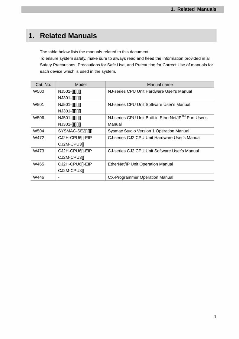
The table below lists the manuals related to this document.
To ensure system safety, make sure to always read and heed the information provided in all
Safety Precautions, Precautions for Safe Use, and Precaution for Correct Use of manuals for
each device which is used in the system.
Cat. No. Model Manual name
W500 NJ501-[][][][]
NJ301-[][][][]
NJ-series CPU Unit Hardware User's Manual
W501 NJ501-[][][][]
NJ301-[][][][]
NJ-series CPU Unit Software User's Manual
W506 NJ501-[][][][]
NJ301-[][][][]
NJ-series CPU Unit Built-in EtherNet/IPTM Port User's
Manual
W504 SYSMAC-SE2[][][] Sysmac Studio Version 1 Operation Manual
W472 CJ2H-CPU6[]-EIP
CJ2M-CPU3[]
CJ-series CJ2 CPU Unit Hardware User's Manual
W473 CJ2H-CPU6[]-EIP
CJ2M-CPU3[]
CJ-series CJ2 CPU Unit Software User's Manual
W465 CJ2H-CPU6[]-EIP
CJ2M-CPU3[]
EtherNet/IP Unit Operation Manual
W446 - CX-Programmer Operation Manual

2. Terms and Definitions
2
2. Terms and Definitions
Term Explanation and Definition
Node Controllers and devices are connected to the EtherNet/IP network via the
EtherNet/IP ports. The EtherNet/IP recognizes each EtherNet/IP port
connected to the network as one node.
When a device with two EtherNet/IP ports is connected to the
EtherNet/IP network, the EtherNet/IP recognizes this device as two
nodes.
The EtherNet/IP achieves the communications between controllers or the
communications between controllers and devices by exchanging data
between these nodes connected to the network.
Tag A minimum unit of the data that is exchanged on the EtherNet/IP network
is called a tag. The tag is defined as a network variable or as a physical
address, and it is allocated to the memory area of each device.
Tag set In the EtherNet/IP network, a data unit that consists of two or more tags
can be exchanged. The data unit consisting of two or more tags for the
data exchange is called a tag set. Up to eight tags can be configured per
tag set for OMRON controllers.
Tag data link In the EtherNet/IP, the tag and tag set can be exchanged cyclically
between nodes without using the user program. This standard feature on
the EtherNet/IP is called a tag data link.
Connection A connection is used to exchange data as a unit within which data
concurrency is maintained. The connection consists of tags or tag sets.
Creating the concurrent tag data link between the specified nodes is
called a "connection establishment ". When the connection is
established, the tags or tag sets that configure the connection are
exchanged between the specified nodes concurrently.
Originator and
Target
To perform tag data links, one node requests the opening of a
communications line called a "connection".
The node that requests opening the connection is called "originator", and
the node that receives the request is called a "target".
Tag data link
parameter
The tag data link parameter is the setting data to perform the tag data
link. It includes the data to set tags, tag sets, and connections.

3. Precautions
3
3. Precautions
(1) Understand the specifications of devices which are used in the system. Allow some
margin for ratings and performance. Provide safety measures, such as installing safety
circuit in order to ensure safety and minimize risks of abnormal occurrence.
(2) To ensure system safety, always read and heed the information provided in all Safety
Precautions, Precautions for Safe Use, and Precaution for Correct Use of manuals for
each device used in the system.
(3) The user is encouraged to confirm the standards and regulations that the system must
conform to.
(4) It is prohibited to copy, to reproduce, and to distribute a part or the whole of this
document without the permission of OMRON Corporation.
(5) The information contained in this document is current as of September 2013. It is subject
to change without notice for improvement.
The following notation is used in this document.
Indicates a potentially hazardous situation which, if not avoided, will result in minor or moderate injury, or may result in serious injury or death.Additionally there may be significant property damage.
Precautions for Safe Use
Precautions on what to do and what not to do to ensure safe usage of the product.
Precautions for Correct Use
Precautions on what to do and what not to do to ensure proper operation and performance.
Additional Information
Additional information to read as required. This information is provided to increase understanding or make operation easier.
Symbol
4. Overview
4
4. Overview
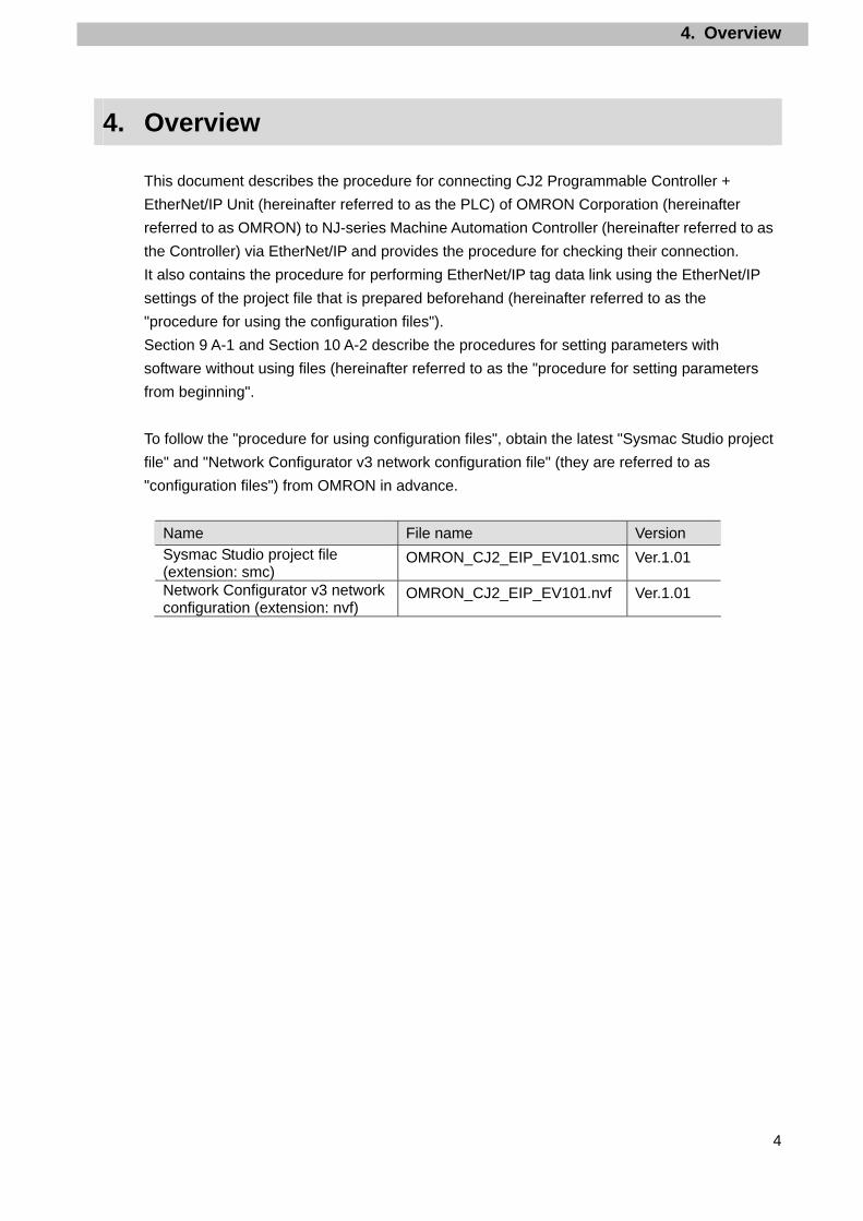
This document describes the procedure for connecting CJ2 Programmable Controller +
EtherNet/IP Unit (hereinafter referred to as the PLC) of OMRON Corporation (hereinafter
referred to as OMRON) to NJ-series Machine Automation Controller (hereinafter referred to as
the Controller) via EtherNet/IP and provides the procedure for checking their connection.
It also contains the procedure for performing EtherNet/IP tag data link using the EtherNet/IP
settings of the project file that is prepared beforehand (hereinafter referred to as the
"procedure for using the configuration files").
Section 9 A-1 and Section 10 A-2 describe the procedures for setting parameters with
software without using files (hereinafter referred to as the "procedure for setting parameters
from beginning".
To follow the "procedure for using configuration files", obtain the latest "Sysmac Studio project
file" and "Network Configurator v3 network configuration file" (they are referred to as
"configuration files") from OMRON in advance.
Name File name Version Sysmac Studio project file (extension: smc)
OMRON_CJ2_EIP_EV101.smc Ver.1.01
Network Configurator v3 network configuration (extension: nvf)
OMRON_CJ2_EIP_EV101.nvf Ver.1.01

5. Applicable Devices and Device Configuration
5
5. Applicable Devices and Device Configuration
5.1. Applicable Devices
The applicable devices are as follows:
Manufacturer Name Model OMRON NJ-series CPU Unit NJ501-[][][][]
NJ301-[][][][] OMRON CJ2 CPU Unit CJ2[]-CPU[][]
OMRON EtherNet/IP Unit CJ1W-EIP21 CJ2H-CPU6[]-EIP CJ2M-CPU3[]
Precautions for Correct Use
As applicable devices above, the devices with the models and versions listed in Section 5.2.
are actually used in this document to describe the procedure for connecting devices and
checking the connection.
You cannot use devices with versions lower than the versions listed in Section 5.2.
To use the above devices with versions not listed in Section 5.2 or versions higher than those
listed in Section 5.2, check the differences in the specifications by referring to the manuals
before operating the devices.
Additional Information This document describes the procedure to establish the network connection. Except for the
connection procedure, it does not provide information on operation, installation or wiring
method. It also does not describe the functionality or operation of the devices. Refer to the
manuals or contact your OMRON representative.

5. Applicable Devices and Device Configuration
6
5.2. Device Configuration
The hardware components to reproduce the connection procedure of this document are as
follows:
Manufacturer
Name Model Version
OMRON NJ-series CPU Unit (Built-in EtherNet/IP port)
NJ501-1500 Ver.1.05
OMRON Power Supply Unit NJ-PA3001 OMRON Switching Hub W4S1-05C Ver.1.00 OMRON Sysmac Studio SYSMAC-SE2[][][] Ver.1.06 OMRON Network-Configurator (Included in Sysmac Studio.) Ver.3.55 OMRON Sysmac Studio project file OMRON_CJ2_EIP_EV101.smc Ver.1.01 OMRON Network Configurator v3 network
configuration file OMRON_CJ2_EIP_EV101.nvf Ver.1.01
- Personal computer (OS: Windows7)
-
- USB cable (USB 2.0 type B connector)
-
- LAN cable (STP (shielded, twisted-pair) cable of Ethernet category 5 or higher)
-
OMRON PLC CPU Unit (Built-in EtherNet/IP port)
CJ2M-CPU32 (Built-in CJ2M-EIP21)
Ver.2.0 (Ver.2.1)
OMRON Power Supply Unit CJ1W-PA202
OMRON CX-One CXONE-AL[][]C-V4
/AL[][]D-V4
Ver.4.[][]
OMRON CX-Programmer (Included in CX-One.) Ver.9.43
Personal computer (Sysmac Studio and CX-One installed, OS: Windows 7)
USB cable
LAN cable
NJ501-1500 (Built-in EtherNet/IP port)
Switching Hub W4S1-05C
CJ2M-CPU32 (Built-in EtherNet/IP port)
USB cable

5. Applicable Devices and Device Configuration
7
Precautions for Correct Use
Prepare the latest "Sysmac Studio project file" and "Network Configurator v3 network
configuration file" from OMRON in advance.
(To obtain the files, contact your OMRON representative.)
Precautions for Correct Use
Update the Sysmac Studio and CX-Programmer to the versions specified in this section or
higher versions using the auto update function.
If a version not specified in this section is used, the procedures described in Section 7 and
subsequent sections may not be applicable. In that case, use the equivalent procedures
described in the Sysmac Studio Version 1 Operation Manual (Cat. No. W504), Network
Configurator Online Help and CX-Programmer Operation Manual (Cat. No. W466).
Additional Information The system configuration in this document uses USB for the connection to the Controller. For
information on how to install a USB driver, refer to A-1 Driver Installation for Direct USB Cable
Connection of the Sysmac Studio Version 1 Operation Manual (Cat. No. W504).
Additional Information The system configuration in this document uses USB for the connection between the
personal computer and PLC. For information on how to install the USB driver, refer to A-5
Installing the USB Driver of the CJ-series CJ2 CPU Unit Hardware User's Manual (Cat. No.
W472).

6. EtherNet/IP Settings
8
6. EtherNet/IP Settings
This section describes the specifications such as communication parameters and tag data link
that are defined in this document.
Hereinafter, the PLC is referred to as the "destination device" in some descriptions.
6.1. EtherNet/IP Communications Parameters
The communications parameters required to connect the Controller and the destination device
via EtherNet/IP are given below.
Controller (Node 1) PLC (Node 2)
IP address 192.168.250.1 192.168.250.2
Subnet mask 255.255.255.0 255.255.255.0
6.2. Allocating the Tag Data Links
The data in the tag data links of the destination device are allocated to the global variables of
the Controller. The relationship between the device data and the global variables is shown
below.
The following global variables are defined in the "Configuration file".
■Output area (Controller → PLC)
Offset Destination device data Global variable Data type Retained
+0 to +9 PLC D10100 onwards
(20byte) EIP002_D10100_OUT WORD[10]
Retained
■Input area (Controller ← PLC)
Offset Destination device data Global variable Data type Retained
+0 to +9 PLC D10000 onwards
(20byte) EIP002_D10000_IN WORD[10]
Retained
Additional Information With the Sysmac Studio, two methods can be used to specify an array for a data type. After
specifying, (1) is converted to (2) and the data type is always displayed as (2).
(1)WORD[3]/(2)ARRAY[0..2]OF WORD
In this document, the data type is simplified by displaying WORD[3].
(The example above means a WORD data type with three array elements.)

7. EtherNet/IP Connection Procedure
9
Personal computer
Destination
device
Controller
7. EtherNet/IP Connection Procedure
This section describes the procedure for connecting the PLC and the Controller via
EtherNet/IP using the "procedure for using configuration files".
This document explains the procedures for setting up the Controller and the PLC from the
factory default setting. For the initialization, refer to Section 8 Initialization Method.
■Setting Overview
The following figure shows the relationship between the processes to operate the
EtherNet/IP tag data link using the "procedure for using configuration files".
Precautions for Correct Use
Prepare the latest "Sysmac Studio project file" and "Network Configurator v3 network
configuration file" from OMRON in advance.
(To obtain the files, contact your OMRON representative.)
Transferring the project data
Importing the project file
Transferring the tag data link parameters
Reading the network configuration file
Sysmac Studio project file
Network Configurator v3 network configuration file
Configuration file
Network Configurator Sysmac Studio

7. EtherNet/IP Connection Procedure
10
7.1. Work Flow
Take the following steps to operate the tag data link for EtherNet/IP.
7.2. Setting Up the PLC Set up the PLC.
↓ 7.2.1. Hardware Settings Set the hardware switches on the PLC and wire
the network. ↓
7.2.2. Starting the CX-Programmer
and Connecting Online with the
PLC
Start the CX-Programmer and connect online with the PLC.
↓ 7.2.3. Parameter Settings Create the I/O table for the PLC and set the IP
address. ↓
7.3. Setting Up the Controller Set up the Controller.
↓ 7.3.1. Starting the Sysmac Studio and
Importing the Project File
Start the Sysmac Studio and import the Sysmac Studio project file.
↓ 7.3.2. Connecting Online and
Transferring the Project Data
Connect online with the Sysmac Studio and transfer the project data to the Controller.
↓
7.4. Setting Up the Network Set the tag data links for the EtherNet/IP.
↓ 7.4.1. Opening the Network
Configuration File and
Connecting Online
Open the Network Configurator v3 network configuration file and connect online with the Controller.
↓ 7.4.2. Transferring the Tag Data Link
Parameters
Transfer the tag data link parameters to the Controller.
↓
7.5. Checking EtherNet/IP
Communications
Confirm that the EtherNet/IP tag data links are operated normally.
↓ 7.5.1 Checking the Connection Status Check the connection status of EtherNet/IP.
↓ 7.5.2 Checking the Data that are Sent
and Received
Confirm that the correct data are sent and received.

7. EtherNet/IP Connection Procedure
11
7.2. Setting Up the PLC
Set up the PLC.
7.2.1. Hardware Settings Set the hardware switches on the PLC and wire the network.
Precautions for Correct Use
Make sure that the power supply is OFF when you perform the setting up.
1 Make sure that the power supply
to the PLC is OFF.
*If the power supply is turned
ON, settings may not be
applicable as described in the
following procedure.
2 Check the hardware switches
located on the front panel of the
EtherNet/IP Unit by referring to
the right figure.
3 Set the unit number setting
switch to 0.
The unit number is used to identify individual CPU Bus Units when more thanone CPU Bus Unit is mounted to the same PLC. Use a small screwdriver to make the setting, taking care not to damage the rotary switch. The unit number is factory-set to 0.
4 Set the node address setting
switches as follows:
[NODE No.x161]: 0
[NODE No.x160]: 2
IP address: 192.168.250.2
*By default, the first to third
octets of the local IP address
are fixed to 192.168.250. The
fourth octet is the values that
were set with the node address
setting switches.
With the FINS communications service, when there are multiple EtherNet/IP Units connected to the Ethernet network, the EtherNet/IP Units are identified by node addresses. Use the node address switches to set the node address between 01 and FE hexadecimal (1 to 254 decimal).Do not set a number that has already been set for another node on the same network.
The left switch sets the sixteens digit (most significant digit) and the right switch sets the ones digit (least significant digit).The node address is factory-set to 01. Default IP address = 192.168.250.node address With the factory-default node address setting of 01, the default IP address is 192.168.250.1.

7. EtherNet/IP Connection Procedure
12
5 Connect the LAN cable to the
EtherNet/IP port of the PLC, and
connect the USB cable to the
USB port. Connect the personal
computer, Switching Hub and
PLC as shown in 5.2. Device
Configuration.
6 Turn ON the power supply to the
PLC.
The set IP address is displayed
on the seven-segment LED
indicators from right to left.
Afterwards, the rightmost 8 bits
of the IP address are displayed
in hexadecimal during normal
operation.
USB cable
LAN cable
Switching HubPLC
CPU Unit
Power Supply Unit

7. EtherNet/IP Connection Procedure
13
7.2.2. Starting the CX-Programmer and Connecting Online with the PLC Start the CX-Programmer and connect online with the PLC.
Install the CX-One and USB driver in the personal computer beforehand.
1 Start the CX-Programmer.
2 Select Auto Online - Direct
Online from the PLC Menu.
3 The Direct Online Dialog Box is
displayed. Select the USB
Connection Option for
Connection Type and click the
Connect Button.
4 The dialog box on the right is
displayed. Check the contents
and click the No Button.

7. EtherNet/IP Connection Procedure
14
5 The dialog box on the right is
displayed, and the
CX-Programmer and the PLC is
automatically connected.
6 Confirm that the
CX-Programmer and the PLC
are normally connected online.
*The icon is pressed down during online connection.
Additional Information If the CX-Programmer and PLC are not connected online, please check the connection of the
cable.
Or, return to step 2, check the settings and repeat each step.
Refer to Connecting Directly to a CJ2 CPU Unit Using a USB Cable in Chapter 3
Communications in PART 3: CX-Server Runtime of the CX-Programmer Operation Manual
(Cat. No. W466) for details.
Additional Information The dialogs explained in the following procedures may not be displayed depending on the
environmental setting of CX-Programmer.
For details on the environmental setting, refer to Options and Preferences in Chapter 3
Project Reference in PART 1: CX-Programmer of the CX-Programmer Operation Manual
(Cat. No. W466). This document explains the setting procedure when the Confirm all
operations affecting the PLC Check Box is selected.

7. EtherNet/IP Connection Procedure
15
7.2.3. Parameter Settings Create the I/O table for the PLC and set the IP address.
1 If the operating mode of the PLC is RUN Mode or Monitor Mode, change it to Program Mode by following the steps below. (1)Select Operating Mode -
Program from the PLC Menu of the CX-Programmer.
(2)The dialog box on the right is
displayed. Confirm that there is no problem and click the Yes Button.
*Refer to Additional Information on the previous page for the settings concerning the dialog display.
(3)Confirm that Stop/Program
Mode is displayed on the right of the PLC model in the project workspace of the CX-Programmer.
(Project workspace)

7. EtherNet/IP Connection Procedure
16
2 Select Edit - I/O Table and Unit
Setup from the PLC Menu of the
CX-Programmer.
The PLC IO Table Window is
displayed.
3 Select Create from the Options
Menu of the PLC IO Table
Window.
The dialog box on the right is
displayed. Confirm that there is
no problem and click the Yes
Button.
The dialog box on the right is
displayed. Confirm that there is
no problem and click the Yes
Button.

7. EtherNet/IP Connection Procedure
17
4 The Transfer from PLC Dialog
Box is displayed. Select the I/O
Table Check Box and the SIO
Unit Parameters Check Box,
and click the Transfer Button.
When the transfer is completed,
the Transfer Results Dialog Box
is displayed.
Confirm that the transfer was
normally executed by referring
to the message in the dialog
box.
When the I/O table is created
normally, the dialog box shows
the following,
Transfer Success: 1 Unit
Transfer Unsuccessful: 0 Unit
Click the OK Button.

7. EtherNet/IP Connection Procedure
18
5 On the PLC IO Table Window, click + to the left of Built-in Port/Inner Board to display CJ2M-EIP21. *The right figure displays the CPU Unit (built-in EtherNet/IP port) specified in 5.2. Device Configuration. When you use an EtherNet/IP Unit not specified in 5.1. Applicable Devices, the display position and name are different from this figure.
Right-click CJ2M-EIP21 and select Unit Setup.
6 The Edit Parameters Dialog Box
is displayed. Select the TCP/IP
Tab.
Make the following settings in
the IP Address Field.
•Use the following address:
Select
•IP address: 192.168.250.2
•Subnet mask: 255.255.255.0
Click the Transfer [PC to Unit]
Button.

7. EtherNet/IP Connection Procedure
19
7 The dialog box on the right is
displayed. Confirm that there is
no problem and click the Yes
Button.
Confirm that parameters were
normally transferred to the Unit,
and click the OK Button.
8 A dialog box on the right is
displayed. Check the contents
and click the Yes Button.
When restarting the Unit is
executed, a dialog box shown
on the right is displayed. Check
the contents and click the OK
Button

7. EtherNet/IP Connection Procedure
20
9 To confirm that the IP address
was correctly changed, click the
Compare Button.
10 After confirming that parameters
match, click the OK Button.
11 Click the OK Button on the Edit
Parameters Dialog Box.

7. EtherNet/IP Connection Procedure
21
7.3. Setting Up the Controller
Set up the Controller.
7.3.1. Starting the Sysmac Studio and Importing the Project File Start the Sysmac Studio and import the Sysmac Studio project file.
Install the Sysmac Studio and USB driver in the personal computer beforehand.
1 Connect the LAN cable to the
built-in EtherNet/IP port
(PORT1) of the Controller and
connect the USB cable to the
peripheral (USB) port. Then
connect the personal computer,
Switching Hub, and Controller
by referring to 5.2. Device
Configuration.
Turn ON the power supply to the
Controller.
2 Start the Sysmac Studio.
Click the Import Button.
*If a confirmation dialog box for
an access right is displayed at
start, select to start.
3 The Import File Dialog Box is
displayed. Select
OMRON_CJ2_EIP_EV101.smc
(Sysmac Studio project file) and
click the Open Button.
*Obtain the Sysmac Studio
project file from OMRON.
USB cable
CPU Unit
End Cover
Power Supply Unit
LAN cable
Switching Hub
Controller

7. EtherNet/IP Connection Procedure
22
4 The OMRON_CJ2_EIP_EV101
project is displayed.
The left pane is called Multiview
Explorer, the right pane is called
Toolbox and the middle pane is
called Edit Pane.
*If an error message is
displayed stating "Failed to
Load Descendants", change
the version of the Sysmac
Studio to the version specified
in 5.2. Device Configuration or
higher version.
5 Select Check All Programs
from the Project Menu.
6 The Build Tab Page is displayed
in the Edit Pane.
Confirm that "0 Errors" and "0
Warnings" are displayed.
7 Select Rebuild Controller from
the Project Menu.
8 A confirmation dialog box is
displayed. Confirm that there is
no problem and click the Yes
Button.
9 Confirm that "0 Errors" and "0
Warnings" are displayed in the
Build Tab Page.
Multiview Explorer
Edit Pane Edit Pane Toolbox

7. EtherNet/IP Connection Procedure
23
7.3.2. Connecting Online and Transferring the Project Data Connect online with the Sysmac Studio and transfer the project data to the Controller.
Always confirm safety at the destination node before you transfer a user
program, configuration data, setup data, device variables, or values in memory
used for CJ-series Units from the Sysmac Studio.
The devices or machines may perform unexpected operation regardless of the
operating mode of the CPU Unit.
1 Select Change Device from the
Controller Menu.
2 The Change Device Dialog Box
is displayed.
Confirm that Device and Version
to use are set as shown on the
right.
*If the settings are different,
select the setting items from the
pull-down list.
Click the OK Button.
3 If the settings were changed in
step 2, the Build Dialog Box is
displayed. Check the contents
and click the Yes Button.
4 Select Communications Setup from the Controller Menu.

7. EtherNet/IP Connection Procedure
24
5 The Communications Setup
Dialog Box is displayed.
Select the Direct connection via
USB Option for Connection
Type.
Click the OK Button.
6 Select Online from the
Controller Menu.
*If the dialog box on the right is
displayed, the model or version
of the Controller does not
match that of the project file.
Match the Controller model and
version by changing the device
settings of the project file, and
then repeat the procedure from
step 1 in this section. Close the
dialog box by clicking the OK
Button.
*The model and version
displayed on the confirmation
dialog box differ depending on
the Controller used and the
device setting of the project file.
Close the dialog box by clicking
the OK Button.
*Example of confirmation dialog box
7. EtherNet/IP Connection Procedure
25
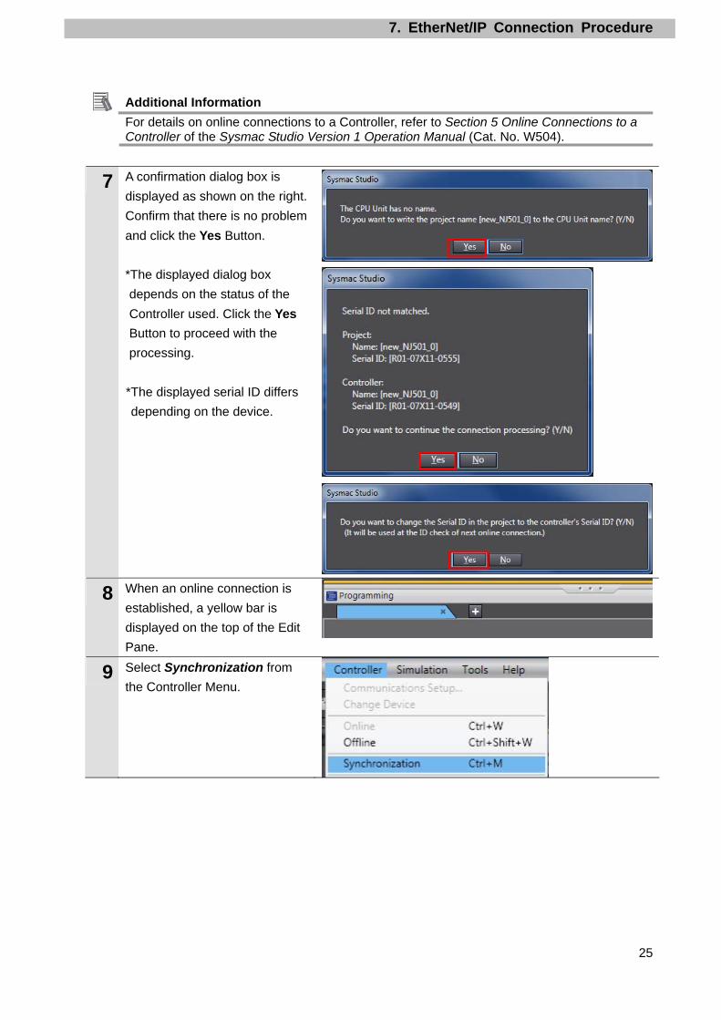
Additional Information For details on online connections to a Controller, refer to Section 5 Online Connections to a Controller of the Sysmac Studio Version 1 Operation Manual (Cat. No. W504).
7 A confirmation dialog box is
displayed as shown on the right.
Confirm that there is no problem
and click the Yes Button.
*The displayed dialog box
depends on the status of the
Controller used. Click the Yes
Button to proceed with the
processing.
*The displayed serial ID differs
depending on the device.
8 When an online connection is
established, a yellow bar is
displayed on the top of the Edit
Pane.
9 Select Synchronization from
the Controller Menu.

7. EtherNet/IP Connection Procedure
26
10 The Synchronization Dialog Box
is displayed.
Confirm that the data to transfer
(NJ501 in the right dialog box) is
selected. Then, click the
Transfer To Controller Button.
*After executing Transfer To Controller, the Sysmac Studio data is transferred to the Controller and the data are compared.
11 A confirmation dialog box is
displayed. Confirm that there is
no problem and click the Yes
Button.
A screen stating "Synchronizing"
is displayed.
A confirmation dialog box is
displayed. Confirm that there is
no problem and click the No
Button.
*Be sure not to return it to "RUN
mode".
7. EtherNet/IP Connection Procedure
27
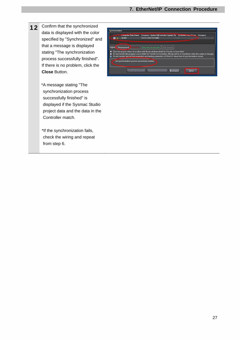
12 Confirm that the synchronized
data is displayed with the color
specified by "Synchronized" and
that a message is displayed
stating "The synchronization
process successfully finished".
If there is no problem, click the
Close Button.
*A message stating "The
synchronization process
successfully finished" is
displayed if the Sysmac Studio
project data and the data in the
Controller match.
*If the synchronization fails,
check the wiring and repeat
from step 6.

7. EtherNet/IP Connection Procedure
28
7.4. Setting Up the Network
Set the tag data links for EtherNet/IP.
7.4.1. Opening the Network Configuration File and Connecting Online Start up the Network Configurator, open the Network Configurator v3 network configuration
file, and connect online with the Controller.
Precautions for Correct Use
Please confirm that the LAN cable is connected before performing the following procedure.
When it is not connected, turn OFF the power supply to each device and then connect the
LAN cable.
1 Start the Network Configurator.
2 Select Open from the File Menu.
3 The Open Dialog Box is
displayed. Select
OMRON_CJ2_EIP_EV101.nvf
(Network Configurator v3
network configuration file) and
click the Open Button.
*Obtain the Network
Configurator v3 network
configuration file from OMRON.
Network Configuration Hardware List

7. EtherNet/IP Connection Procedure
29
4 The following devices are
displayed in the Network
Configuration Pane as shown in
the right figure.
IP address of node
1:192.168.250.1
IP address of node
2192.168.250.2
5 Select Select Interface - NJ
Series USB Port from the
Option Menu.
6 Select Connect from the
Network Menu.
7 The Select Connect Network
Port Dialog Box is displayed.
Select TCP:2.
Click the OK Button.

7. EtherNet/IP Connection Procedure
30
8 The Select Connected Network
Dialog Box is displayed. Check
the contents and click the OK
Button.
9 When an online connection is
established normally, the color
of the icon on the right figure
changes to blue.
Additional Information If an online connection cannot be made to the Controller, check the cable connection. Or,
return to step 5, check the settings and repeat each step.
For details, refer to 7-2-8 Connecting the Network Configurator to the Network in Section 7
Tag Data Link Functions of the NJ-series CPU Unit Built-in EtherNet/IP Port User's Manual
(Cat. No. W506).

7. EtherNet/IP Connection Procedure
31
7.4.2. Transferring the Tag Data Link Parameters Transfer the tag data link parameters to the Controller.
1 Select Download from the
Network Menu.
The dialog box on the right is
displayed. Confirm that there is
no problem and click the Yes
Button.
2 Tag data link parameters are
downloaded from the Network
Configurator to the Controller.
3 The dialog box on the right is
displayed. Check the contents
and click the OK Button.

7. EtherNet/IP Connection Procedure
32
7.5. Checking the EtherNet/IP Communications
Confirm that the EtherNet/IP tag data links are operated normally.
7.5.1. Checking the Connection Status Check the connection status of EtherNet/IP.
1 Confirm that the tag data links are
normally in operation by checking
the LED indicators on each device.
•Controller (Built-in EtherNet/IP port)
LED indicators in normal status:
[NET RUN]: Lit green
[NET ERR]: Not lit
[LINK/ACT]: Flashing yellow
(Flashing while packets are being
sent and received)
•PLC (EtherNet/IP Unit)
LED indicators in normal status:
[MS]: Lit green
[NS]: Lit green
[COMM]: Lit yellow
[100M] or [10M]: Lit yellow
(Controller)
(EtherNet/IP Unit)
2 Confirm that the tag data links are
normally in operation by checking
the status information on the Device
Monitor Window of the Network
Configurator.
Right-click the device icon of node 1
on the Network Configuration Pane
and select Monitor.

7. EtherNet/IP Connection Procedure
33
3 The dialog box on the right displays
the Status 1 Tab Page of the Device
Monitor Dialog Box.
When the same items in the right
dialog box are selected, the data
links are normally in operation.
Click the Close Button.
4 Select Disconnect from the
Network Menu to go offline. The
color of the icon on the figure
changes from blue.
Select Exit from the File Menu to
exit the Network Configurator.
Number: Node number
Blue: Connection normal

7. EtherNet/IP Connection Procedure
34
7.5.2. Checking the Data that are Sent and Received Confirm that the correct data are sent and received.
Always confirm safety at the destination node before you transfer a user
program, configuration data, setup data, device variables, or values in memory
used for CJ-series Units from the Sysmac Studio.
The devices or machines may perform unexpected operation regardless of the
operating mode of the CPU Unit.
1 Select Watch Tab Page from the
View Menu.
2 The Watch Window1 Tab Page is
displayed in the lower section of the
Edit Pane.
3 The following names are entered in
the Watch Window1 Tab Page for
monitoring. EIP002_D10100_OUT[0] EIP002_D10100_OUT[1] EIP002_D10000_IN[0] EIP002_D10000_IN[1]
4 Enter 1234 in the Modify Column of
EIP002_D10100_OUT[0].
After entering the value, press the
Enter Key. The online value of
EIP002_D10100_OUT[0] changes
to 1234.
Enter 5678 in the Modify Column of
EIP002_ D10100_OUT[1] in the
same way.
The online value changes to 5678.

7. EtherNet/IP Connection Procedure
35
5 Display the CX-Programmer.
Confirm that the PLC is in
PROGRAM mode.
*If the CX-Programmer is online and
the PLC is not in PROGRAM
mode, change to PROGRAM mode
by following Section 7.3.2.
6 Select Edit - Memory from the PLC
Menu.
7 The PLC Memory Window is
displayed.
Double-click D from a list in the PLC
Memory Window.

7. EtherNet/IP Connection Procedure
36
8 The D Window is displayed.
Enter 10100 in the Start Address
Field.
9 Select Display - Hexadecimal from
the View Menu.
10 Select Monitor from the Online
Menu.
11 The Monitor Memory Areas Dialog
Box is displayed.
Select the D Check Box and click
the Monitor Button.
12 The values from D10100 are
displayed.
You can confirm that D10100 is
1234 and D10101 is 5678 as set in
step 4.
13 Enter 10000 in the Start Address
Field.

7. EtherNet/IP Connection Procedure
37
14 Select D10000 and click the
SetValue Button.
15 The Set Value Dialog Box is
displayed. Enter 9876 in the Value
Field.
Click the OK Button.
16 Confirm that the value of D10000 is
9876.
17 Change D10001 to 5432 in the
same way as steps 14 to 16.
18 Display the Sysmac Studio.
Confirm that the online values of
EIP002_D10000_IN[0] and
EIP002_D10000_IN[0] are 9876
and 5432.
You can confirm that the values are
the same as the ones set in steps
14 to 17.

8. Initialization Method
38
8. Initialization Method
This document explains the setting procedure from the factory default setting.
Some settings may not be applicable as described in this document unless you use the
devices with the factory default setting.
8.1. Initializing the Controller
To initialize the Controller, it is necessary to initialize the CPU Unit and EtherNet/IP port.
Change to PROGRAM Mode before the initialization.
8.1.1. EtherNet/IP port Delete the connection information and tag information that are set for the EtherNet/IP port.
Follow the procedure below to set blank connection information and blank tag information
and delete them using the Network Configurator.
(1)Deleting connection information
In the Connections Tab Page of the Edit Device Parameters Dialog Box, move all devices
registered in the Register Device List to the Unregister Device List.
If a confirmation dialog box is displayed when you remove devices from the registration list,
click the Yes Button.
No registered
devices

8. Initialization Method
39
(2)Deleting tag information
In the Tag Sets Tab Page of the Edit Parameters Dialog Box, click the Delete all of unused
Tag Sets Button.
If a confirmation dialog box is displayed when deleting, click the Yes Button.
(3)Download
Right-click the Controller and select Parameter - Download from the menu that is
displayed.
No registered
tags

8. Initialization Method
40
8.1.2. CPU Unit To initialize the settings of the CPU Unit, select Clear All Memory from the Controller
Menu of the Sysmac Studio. The Clear All Memory Dialog Box is displayed. Check the
contents and click the OK Button.

8. Initialization Method
41
8.2. Initializing the PLC
To initialize the settings of the PLC, it is necessary to initialize the CPU Unit and the
EtherNet/IP Unit. Change to PROGRAM mode before the initialization.
8.2.1. EtherNet/IP Unit (1)Select Edit - I/O Table and Unit Setup from the PLC Menu of the CX-Programmer.
Right-click the EtherNet/IP Unit on the PLC IO Table Window and select Unit Setup from the
menu.
(2)Click the Restart Button on the Edit Parameters Dialog Box.
(3)A dialog box is displayed confirming the execution. Confirm that there is no problem and
click the Yes Button. Then, on the Restart Unit Dialog Box, select the Return to out-of-box
configuration, and then emulate cycling power Option, and click the OK Button. A dialog box
is displayed indicating the execution is completed. Check the contents and click the OK
Button.

8. Initialization Method
42
8.2.2. CPU Unit To initialize the settings of the CPU Unit, select Clear All Memory Areas from the PLC
Menu of the CX-Programmer. On the Confirm All Memory Area Clear Dialog Box, select
the Initialize Option and click the OK Button.

9. Appendix 1 Detailed Settings of the Tag Data Links
43
9. Appendix 1 Detailed Settings of the Tag Data Links
This section provides the detailed settings necessary to execute tag data links which are set in
this document.
9.1. Global Variable Table
The Controller accesses the data in tag data links as global variables. The following are the
settings of the global variables. Use the Sysmac Studio to register a global variable table.
Name Data type RetainedNetwork publish
Destination device allocation
EIP002_D10100_OUT WORD[10] Retained Output PLC D10100~
(20byte)
EIP002_D10000_IN WORD[10] Retained Input PLC D10000~
(20byte)
Additional Information With the Sysmac Studio, two methods can be used to specify an array for a data type. After
specifying, (1) is converted to (2) and the data type is always displayed as (2).
(1)WORD[3]/(2)ARRAY[0..2]OF WORD
In this document, the data type is simplified by displaying WORD[3].
(The example above means a WORD data type with three array elements.)
9.2. Relationship between Destination Device and Global Variables
Global variables need to be arranged in offset order of the destination device before setting
the tag data link parameters.
The relationship between the memory allocation of the destination device and the global
variables is shown below.
■Output area (Controller → PLC)
Offset Destination device data Global variable Data type Retained
+0 to +9 PLC D10100 onwards
(20byte) EIP002_D10100_OUT WORD[10]
Retained
■Input area (Controller ← PLC)
Offset Destination device data Global variable Data type Retained
+0 to +9 PLC D10000 onwards
(20byte) EIP002_D10000_IN WORD[10]
Retained

9. Appendix 1 Detailed Settings of the Tag Data Links
44
9.3. Associating the Tag Data Links
Tag data link parameters are required to perform tag data links with a destination device.
Follow the procedures below to associate the tag data links.
(1)Use the Sysmac Studio to define the global variables to publish on the network.
Store the created global variables in a CSV file to use in the Network Configurator.
(2)Read the CSV file (tag list) created in step 1 to the Network Configurator.
(3)Make a single tag set that includes the tag lists.
(4)Link the tag set with the destination device information and create tag data link
parameters.
The numbers shown in the tables below correspond to the steps above.
■Output area (Controller → PLC) Controller setting (Set with Sysmac Studio.)
Data link table setting (Set with Network Configurator.)
Destination device information
(1)
Tag set: EIP002_OUT
20byte (4)
← D10100-[20Byte]
Global variable (3) Tag list EIP002_D10100_OUT
WORD [10]
→(2)
EIP002_D10100_OUT
(20byte)
*Refer to 9.2 for details.
■Input area (Controller ← PLC) Controller setting (Set with Sysmac Studio.)
Data link table setting (Set with Network Configurator.)
Destination device information
(1)
Tag set: EIP002_IN
20byte (4)
← D10000-[20Byte]
Global variable (3) Tag list EIP002_D10000_IN
WORD [10]
→(2)
EIP002_D10000_IN
(20byte)
*Refer to 9.2 for details.

10. Appendix 2 Setting the Tag Data Links Using the Software
45
Personal computer
Global variable
(CSV file)
Destination
device
Controller
10. Appendix 2 Setting the Tag Data Links Using the
Software
This section describes the procedure for setting the Controller without the configuration files
(Procedure for setting parameters from the beginning).
You can also refer to this section when you want to change the parameters of the
configuration files.
10.1. Overview of Setting Tag Data Links
The following is the relationship between the processes to operate the tag data links using the
"procedure for setting parameters from the beginning".
Settings made with Sysmac Studio •Setting parameters (IP address, etc.)
•Setting global variables (name, network setting and task setting, etc.)
•Exporting global variables •Building
Transferring the Project Data
Transferring tag data link parameters
Settings made with Network Configurator •Uploading network configuration •Importing CSV file (tag name) •Tag registration •Connection setting (associating tags)
Network Configurator Sysmac Studio

10. Appendix 2 Setting the Tag Data Links Using the Software
46
10.2. Work Flow of "Procedure for Setting Parameters from the Beginning"
Take the following steps to make the tag data link settings for EtherNet/IP using the
"procedure for setting parameters from the beginning"
This section describes the detailed procedures for 10.3. Setting Up the Controller Using the
Software and 10.4. Setting Up the Network Using the Software (in red frames below).
The procedures for 7.3 Setting Up the PLC and 7.6 Checking the EtherNet/IP
Communications" are the same as the "procedure for using the configuration files". Refer to
the procedures in Section 7.
7.2. Setting Up the PLC Set up the PLC.
↓ 7.2.1. Hardware Settings Set the hardware switches on the PLC and wire the
network. ↓
7.2.2. Starting the CX-Programmer
and Connecting Online with the
PLC
Start the CX-Programmer and connect online with the PLC.
↓ 7.2.3. Parameter Settings Create the I/O table for the PLC and set the IP
address. ↓
10.3. Setting Up the Controller Using
the Software
Set up the Controller using the software.
↓ 10.3.1. Starting the Sysmac Studio and
Setting the Parameters for the
Controller
Start the Sysmac Studio and set the parameters for the Controller.
↓ 10.3.2. Setting the Global Variables Set the global variables to use for the tag data links.
↓ 10.3.3. Exporting the Global Variables Export the global variables in a CSV file to use as
tags in the Network Configurator. ↓
10.3.4. Connecting Online and
Transferring the Project Data
Connect online with the Sysmac Studio and transfer the project data to the Controller.
↓ 10.3.5. Settings in the Watch Tab Page To check data that is sent and received, make
settings in the Watch Tab Page. ↓

10. Appendix 2 Setting the Tag Data Links Using the Software
47
10.4. Setting Up the Network Using the
Software
Set the tag data links for EtherNet/IP using the software.
↓ 10.4.1. Connecting Online and
Uploading Configuration
Start the Network Configurator, connect online with the Controller, and upload the network configuration.
↓
10.4.2. Setting the Tags and Tag Sets Set the tags and tag sets of the send area and receive area of the PLC.
↓ 10.4.3. Importing the File, Registering
the Tags and Setting the Tag
Sets
Import the CSV file that was saved, register tags of the originator's send area and receive area, and set the tag sets.
↓ 10.4.4. Setting the Connection Associate the tags of the target device with the tags
of the originator. ↓
10.4..5 Transferring the Tag Data Link
Parameters
Transfer the set tag data link parameters to the Controller.
↓
7.5. Checking EtherNet/IP
Communications
Confirm that the EtherNet/IP tag data links are operated normally.
↓ 7.5.1 Checking the Connection Status Check the connection status of EtherNet/IP.
↓ 7.5.2 Checking the Data that are Sent
and Received
Confirm that the correct data are sent and received.
10. Appendix 2 Setting the Tag Data Links Using the Software
48
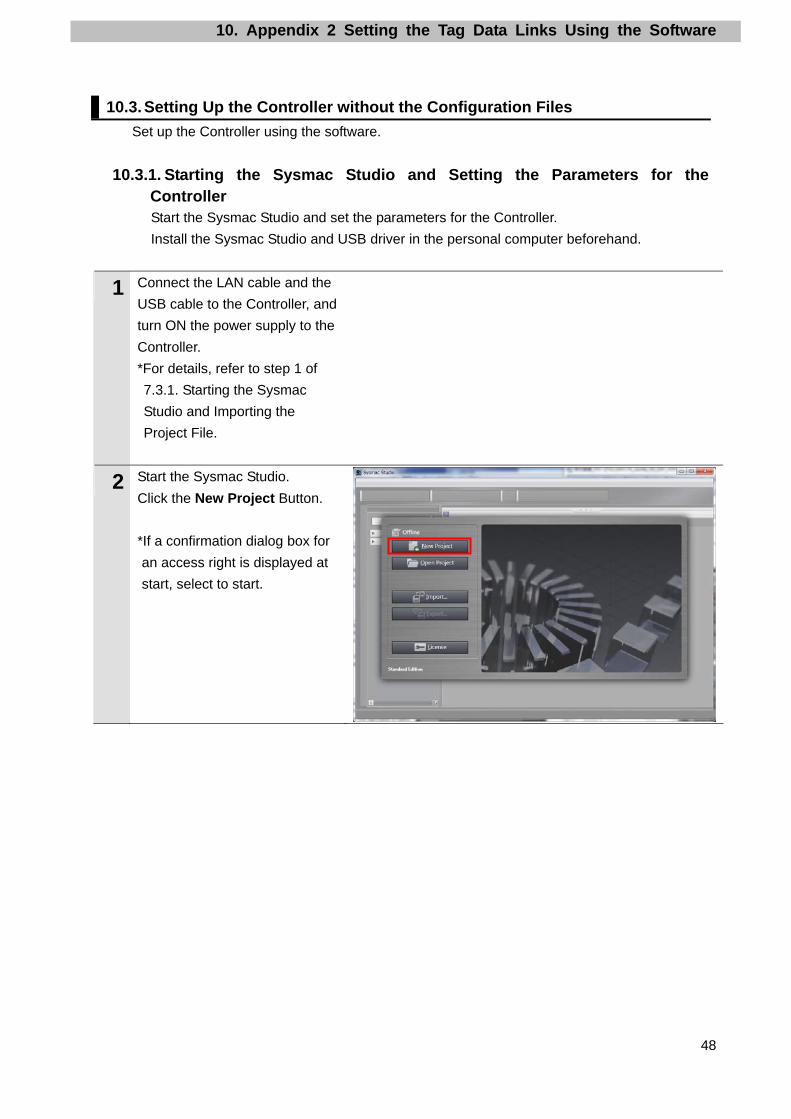
10.3. Setting Up the Controller without the Configuration Files
Set up the Controller using the software.
10.3.1. Starting the Sysmac Studio and Setting the Parameters for the Controller Start the Sysmac Studio and set the parameters for the Controller.
Install the Sysmac Studio and USB driver in the personal computer beforehand.
1 Connect the LAN cable and the
USB cable to the Controller, and
turn ON the power supply to the
Controller.
*For details, refer to step 1 of
7.3.1. Starting the Sysmac
Studio and Importing the
Project File.
2 Start the Sysmac Studio.
Click the New Project Button.
*If a confirmation dialog box for
an access right is displayed at
start, select to start.

10. Appendix 2 Setting the Tag Data Links Using the Software
49
3 The Project Properties Dialog Box is displayed. *In this document, New Project is set as the project name.
Confirm that Category and Device that you use are set in the Select Device Field. Select version 1.05 from the pull-down list of Version. *Although 1.05 is selected in this document, select the version you actually use.
4 Click the Create Button.
5 The New Project is displayed.
The left pane is called Multiview
Explorer, the right pane is called
Toolbox and the middle pane is
called Edit Pane.
Edit Pane ToolboxMultiview Explorer

10. Appendix 2 Setting the Tag Data Links Using the Software
50
6 Double-click Built-in
EtherNet/IP Port Settings
under Configurations and
Setup - Controller Setup in the
Multiview Explorer.
7 The Built-in EtherNet/IP Port
Settings Tab Page is displayed
in the Edit Pane.
Click the TCP/IP Setting Button,
select the Fixed Setting Check
Box in the IP Address Field, and
make the following settings.
IP address: 192.168.250.1
Subnet mask: 255.255.255.0

10. Appendix 2 Setting the Tag Data Links Using the Software
51
10.3.2. Setting the Global Variables Set the global variables to use for the tag data links.
1 Double-click Global Variables
under Programming - Data in
the Multiview Explorer.
2 The Global Variables Tab Page
is displayed in the Edit Pane.
Click a column under the Name
Column to enter a new variable.
Enter EIP002_D10100_OUT in
the Name Column.
Enter WORD[10] in the Data
Type Column.
*After entering, the value
changes to ARRAY[0..9] OF
WORD as shown on the right.
Select the Retain Check Box to
retain the value.
Select Output from the Network
Publish Menu.

10. Appendix 2 Setting the Tag Data Links Using the Software
52
3 After entering, right-click and
select Create New from the
menu.
4 Enter the following data in the new columns in the same way as steps 2 and 3.
•Name: EIP002_D10000_IN Data type: WORD[10] Retained: Retained Network Publish: Input
5 Double-click Task Settings
under Configurations and
Setup in the Multiview Explorer.
The Task Settings Tab Page is
displayed in the Edit Pane. Click
the Settings for Exclusive
Control Variables in Tasks
Button.
Click the + Button.
6 Click the Down Button under
Variable to be refreshed. The
variables set in steps 2 to 4 are
displayed.
Select EIP002_D10100_OUT.
8 Click the + Button and select a
variable to be refreshed.
*The data types are displayed
automatically, and you do not
have to set them.
Add all variables set in step 4 as
shown in the right figure.

10. Appendix 2 Setting the Tag Data Links Using the Software
53
10.3.3. Exporting the Global Variables Export the global variables in a CSV file to use as tags in the Network Configurator.
1 Double-click Global Variables
under Programming - Data in
the Multiview Explorer.
2 The Global Variables Tab Page
is displayed in the Edit Pane.
Right-click on the pane and
Select Select All.
All the selected variables are
highlighted.
3 Select Export Global Variables
- Network Configurator from
the Tools Menu.
4 The Save As Dialog Box is
displayed. Enter EIP002 in the
File name Field.
Click the Save Button.

10. Appendix 2 Setting the Tag Data Links Using the Software
54
10.3.4. Connecting Online and Transferring the Project Data Connect online with the Sysmac Studio and transfer the project data to the Controller.
Always confirm safety at the destination node before you transfer a user
program, configuration data, setup data, device variables, or values in memory
used for CJ-series Units from the Sysmac Studio.
The devices or machines may perform unexpected operation regardless of the
operating mode of the CPU Unit.
1 Select Check All Programs from the Project Menu.
2 The Build Tab Page is displayed
in the Edit Pane.
Confirm that "0 Errors" and "0
Warnings" are displayed.
3 Select Rebuild Controller from the Project Menu.
4 A confirmation dialog box is
displayed. Check the contents
and click the Yes Button.
5 Confirm that "0 Errors" and "0
Warnings" are displayed in the
Build Tab Page.
6 Select Communications Setup
from the Controller Menu.

10. Appendix 2 Setting the Tag Data Links Using the Software
55
7 The Communications Setup
Dialog Box is displayed.
Select the Direct connection via
USB Option for Connection
Type.
Click the OK Button.
8 Select Online from the
Controller Menu.
A confirmation dialog box is
displayed. Check the contents
and click the Yes Button.
*The displayed dialog box
depends on the status of the
Controller used. Check the
contents and click the Yes
Button to proceed with the
processing.
9 When an online connection is
established, a yellow bar is
displayed on the top of the Edit
Pane.
Additional Information
For details on online connections to a Controller, refer to Section 5 Online Connections to a Controller of the Sysmac Studio Version 1 Operation Manual (Cat. No. W504).
10 Select Synchronization from
the Controller Menu.

10. Appendix 2 Setting the Tag Data Links Using the Software
56
11 The Synchronization Dialog Box
is displayed.
Confirm that the data to transfer
(NJ501 in the right dialog box) is
selected. Then, click the
Transfer To Controller Button.
*After executing Transfer To
Controller, the Sysmac Studio
data is transferred to the
Controller and the data are
compared.
12 A confirmation dialog box is
displayed. Confirm that there is
no problem and click the Yes
Button.
A screen stating "Synchronizing"
is displayed.
A confirmation dialog box is
displayed. Confirm that there is
no problem and click the No
Button.
*Be sure not to return it to "RUN
mode".

10. Appendix 2 Setting the Tag Data Links Using the Software
57
13 Confirm that the synchronized
data is displayed with the color
specified by "Synchronized" and
that a message is displayed
stating "The synchronization
process successfully finished".
If there is no problem, click the
Close Button.
*A message stating "The
synchronization process
successfully finished" is
displayed if the Sysmac Studio
project data and the data in the
Controller match.
*If the synchronization fails,
check the wiring and repeat
from step 1.
10. Appendix 2 Setting the Tag Data Links Using the Software
58
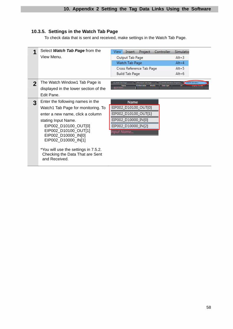
10.3.5. Settings in the Watch Tab Page To check data that is sent and received, make settings in the Watch Tab Page.
1 Select Watch Tab Page from the
View Menu.
2 The Watch Window1 Tab Page is
displayed in the lower section of the
Edit Pane.
3 Enter the following names in the
Watch1 Tab Page for monitoring. To
enter a new name, click a column
stating Input Name. EIP002_D10100_OUT[0] EIP002_D10100_OUT[1] EIP002_D10000_IN[0] EIP002_D10000_IN[1]
*You will use the settings in 7.5.2. Checking the Data That are Sent and Received.

10. Appendix 2 Setting the Tag Data Links Using the Software
59
10.4. Setting Up the Network Using the Software
Set the tag data links for EtherNet/IP using the software.
10.4.1. Connecting Online and Uploading Configuration Start the Network Configurator, connect online with the Controller, and upload the network
configuration.
Precautions for Correct Use
Please confirm that the LAN cable is connected before performing the following procedure.
When it is not connected, turn OFF the power supply to each device and then connect the
LAN cable.
1 Start the Network Configurator.
2 Select Select Interface - NJ
Series USB Port from the
Option Menu.
3 Select Connect from the
Network Menu.
Network Configuration Pane Hardware List

10. Appendix 2 Setting the Tag Data Links Using the Software
60
4 The Select Connect Network
Port Dialog Box is displayed.
Select TCP:2.
Click the OK Button.
5 The Select Connected Network
Dialog Box is displayed. Check
the contents and click the OK
Button.
6 When an online connection is
established normally, the color
of the icon on the right figure
changes to blue.

10. Appendix 2 Setting the Tag Data Links Using the Software
61
Additional Information If an online connection cannot be made to the Controller, check the cable connection. Or,
return to step 1, check the settings and repeat each step.
For details, refer to 7-2-8 Connecting the Network Configurator to the Network in Section 7
Tag Data Link Functions of the NJ-series CPU Unit Built-in EtherNet/IPTM Port User's Manual
(Cat. No. W506).
7 Select Upload from the Network
Menu to upload the device
information on the network.
8 The dialog box on the right is
displayed. Confirm that there is
no problem and click the Yes
Button.
9 The Target Device Dialog Box is
displayed.
Select the192.168.250.1
Checkbox and the
192.168.250.2 Checkbox, and
click the OK Button.
*If 192.168.250.1 or
192.168.250.2 is not displayed
on the dialog box, click the Add
Button to add the address.
*The displayed addresses
depend on the status of the
Network Configurator.

10. Appendix 2 Setting the Tag Data Links Using the Software
62
10 The device parameters are
uploaded. When uploading is
completed, the dialog box on the
right is displayed.
Check the contents and click the
OK Button.
11 After uploading is completed,
confirm that the Network
Configuration Pane shows the
updated IP addresses of the
devices.
IP address of node 1:
192.168.250.1
IP address of node 2:
192.168.250.2

10. Appendix 2 Setting the Tag Data Links Using the Software
63
10.4.2. Setting the Tags and Tag Sets Set the tags and tag sets of the send area and receive area of the PLC.
1 Right-click the node 2 device
and select Parameter - Edit.
2 The Edit Device Parameters
Dialog Box is displayed.
Click the Tab Sets Tab.
3 Click the In - Consume Tab.
Click the New Button.
4 A confirmation dialog box is
displayed. Click the Yes Button.

10. Appendix 2 Setting the Tag Data Links Using the Software
64
5 The Edit Tags Dialog Box is
displayed. Select the In -
Consume Tab and click the
New Button.
6 The Edit Tag Dialog Box is
displayed.
Set the following values and
click the Regist Button.
Name: D10100
Size: 20 bytes

10. Appendix 2 Setting the Tag Data Links Using the Software
65
7 Click the Close Button.
8 The Edit Tag Dialog Box is
displayed.
Confirm that D10100 and
20Byte are displayed.
9 Select the Out-Produce Tab.
Click the New Button.

10. Appendix 2 Setting the Tag Data Links Using the Software
66
10 The Edit Tag Dialog Box is
displayed.
Set the following values and
click the Regist Button.
Name: D10000
Size: 20 Byte
11 Click the Close Button.
10. Appendix 2 Setting the Tag Data Links Using the Software
67
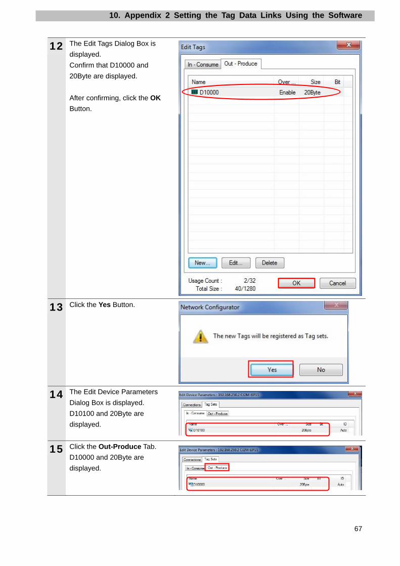
12 The Edit Tags Dialog Box is
displayed.
Confirm that D10000 and
20Byte are displayed.
After confirming, click the OK
Button.
13 Click the Yes Button.
14 The Edit Device Parameters
Dialog Box is displayed.
D10100 and 20Byte are
displayed.
15 Click the Out-Produce Tab.
D10000 and 20Byte are
displayed.
10. Appendix 2 Setting the Tag Data Links Using the Software
68
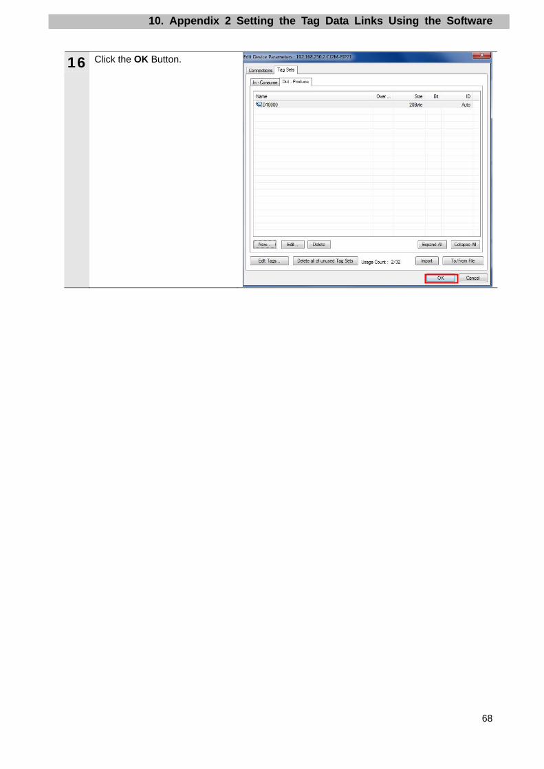
16 Click the OK Button.

10. Appendix 2 Setting the Tag Data Links Using the Software
69
10.4.3. Importing the File, Registering the Tags and Setting the Tag Sets Import the CSV file that was saved, register tags of the originator's send area and receive
area, and set the tag sets.
This section explains the receive settings and then send settings of the target node.
1 On the Network Configuration
Pane of the Network
Configurator, right-click the node
1 device and select Parameter -
Edit.
2 The Edit Device Parameters
Dialog Box is displayed.
Click the To/From File Button.
3 Select Import from File.

10. Appendix 2 Setting the Tag Data Links Using the Software
70
4 The Import Connection
Configuration Dialog Box is
displayed. Select EIP002.csv
and click the Open Button.
*In the Look in Field, specify the
folder in which the file was
saved in Section 10.3.3
Exporting the Global Variables.
5 The right dialog boxes may not
be displayed depending on the
status of the Controller and
software used. In such a case,
proceed to the next step.
The right dialog box is
displayed. Confirm that there is
no problem and click the Yes
Button.
The right dialog box is
displayed. Confirm that there is
no problem and click the No
Button.
Make sure that tag sets are not
created automatically.
6 The Edit Tags Dialog Box is
displayed again.
Click the Tag Sets Tab.

10. Appendix 2 Setting the Tag Data Links Using the Software
71
7 The data on the Tag Sets Tab is
displayed. Select the
In-Consume Tab and click the
Edit Tags.
Here, register an area (node 2
→ node 1) where node 1
receives data.
8 The Edit Tags Dialog Box is
displayed.
Select the In - Consume Tab.
The tab page shows the variable
name that was set in 10.3.2
Setting the Global Variables and
that is listed in 9.2. Relationship
between Destination Device and
Global Variables.

10. Appendix 2 Setting the Tag Data Links Using the Software
72
9 Select the Out-Produce Tab.
In the same way as the previous
step, the tab page shows the
variable name that was set in
10.3.2 Setting the Global
Variables and that is listed in
9.2. Relationship between
Destination Device and Global
Variables.
Click the OK Button.
10 The Edit Tags Dialog Box is
displayed again.
Click the New Button.

10. Appendix 2 Setting the Tag Data Links Using the Software
73
11 The Edit Tag Set Dialog Box is
displayed.
Select EIP002_D10000_IN from
the Candidate Tag List and click
the << Button.
12 EIP002_D10000_IN moves to
the Tag List.
Move all variables from the
Candidate Tag List to the Tag
List in the same way.
13 Enter EIP002_IN in the Name
Field.
Click the Regist Button.
14 The Edit Device Parameters
Dialog Box is displayed. Click
the Close Button.
15 The Edit Device Parameters
Dialog Box is displayed.
EIP002_IN and 20Byte are
displayed.

10. Appendix 2 Setting the Tag Data Links Using the Software
74
16 Select the Out-Produce Tab.
Click the New Button.
17 The Edit Tag Set Dialog Box is
displayed.
Move the variables from the
Candidate Tag List to the Tag
List in the same way as steps 11
and 12.
*Make sure that the data in the
Tag List is arranged in order of
offsets shown in 9.2.
Relationship between
Destination Device and Global
Variables.

10. Appendix 2 Setting the Tag Data Links Using the Software
75
18 Enter EIP002_OUT in the Name
Field.
Click the Regist Button.
19 The Edit Tag Set Dialog Box is
displayed. Click the Close
Button.
20 The Edit Tags Dialog Box is
displayed again.
EIP002_OUT and 20Byte are
displayed.
Select the Connections Tab.

10. Appendix 2 Setting the Tag Data Links Using the Software
76
10.4.4. Setting the Connection Associate the tags of the target device (that receives the open request) with the tags of the
originator (that requests opening).
1 Select 192.168.250.2 in the
Unregister Device List Field.
Click the Down Arrow that is
shown in the dialog box.
2 192.168.250.2 is registered in
the Register Device List.
Select 192.168.250.2 and click
the New Button.
3 The Edit Connection Dialog Box
is displayed. Select the following
values from the pull-down lists
for the settings in the Originator
Device Field and the Target
Device Field.
■Settings of connection
Connection allocation Setting value
Input Tag Set EIP002_IN - [20Byte] Originator device
Connection Type Multi-cast connection
Target Device Output Tag Set D10000 - [20Byte]

10. Appendix 2 Setting the Tag Data Links Using the Software
77
4 Confirm that the settings are
correct and click the Regist
Button.
5 The Edit Connection Dialog Box
is displayed again. Click the
Close Button.
6 The Edit Device Parameters
Dialog Box is displayed again.
Click the OK Button.
7 When the connection is
completely allocated, the
registration destination node
address is displayed under the
device icon of the destination
device on the Network
Configuration Pane.
8 Right-click the node 2 device
and select Parameter - Edit.

10. Appendix 2 Setting the Tag Data Links Using the Software
78
9 Select 192.168.250.1 in the
Unregister Device List Field.
Click the Down Arrow that is
shown in the dialog box.
10 192.168.250.1 is registered in
the Register Device List.
Select 192.168.250.1 and click
the New Button.
11 The Edit Connection Dialog Box
is displayed. Select the following
values from the pull-down lists
for the settings in the Originator
Device Field and the Target
Device Field.
■Settings of connection
Connection allocation Setting value
Input Tag Set D10100 - [20Byte] Originator device
Connection Type Multi-cast connection
Target Device Output Tag Set EIP002_OUT - [20Byte]
12 Confirm that the settings are
correct and click the Regist
Button.

10. Appendix 2 Setting the Tag Data Links Using the Software
79
13 The Edit Connection Dialog Box
is displayed again. Click the
Close Button.
14 The Edit Device Parameters
Dialog Box is displayed again.
Click the OK Button.
15 When the connection is
completely allocated, the
registration destination node
address is displayed under the
device icon of the destination
device on the Network
Configuration Pane.

10. Appendix 2 Setting the Tag Data Links Using the Software
80
10.4.5. Transferring the Tag Data Link Parameters Transfer the set tag data link parameters to the Controller.
1 Select Download from the
Network Menu.
The dialog box on the right is
displayed. Confirm that there is
no problem and click the Yes
Button.
2 Tag data link parameters are
downloaded from the Network
Configurator to the Controller.
3 The dialog box on the right is
displayed. Check the contents
and click the OK Button.

11. Revision History
81
11. Revision History
Revision
code
Date of revision Revision reason and revision page
01 Sep. 6, 2013 First edition

82

2013
0911(-)P568-E1-01


