59
Ethernut-GPIB Interface Manual Raymond Meng Gao Quantum Degenerate Gas Laboratory Prof. Kirk W. Madison Chem/Phys A015/023 UBC August 24, 2005 Version 1.1.21

Ethernut-GPIB Interface Manual
Raymond Meng GaoQuantum Degenerate Gas Laboratory
Prof. Kirk W. MadisonChem/Phys A015/023 UBC
August 24, 2005Version 1.1.21
Contents
1 About this Manual 2
2 Introduction 32.1 Architecture Overview . . . . . . . . . . . . . . . . . . 42.2 Introduction to Ethernut . . . . . . . . . . . . . . . . . 4
2.2.1 How Does the Ethernut Work? . . . . . . . . . 62.2.2 How Does Nut/OS Work? . . . . . . . . . . . . 72.2.3 How Does the FileSystem Work? . . . . . . . . 8
3 Tutorial 93.1 Installing and Loading the Ethernut . . . . . . . . . . . 93.2 Talking GPIB . . . . . . . . . . . . . . . . . . . . . . . 12
3.2.1 SSH Tunneling . . . . . . . . . . . . . . . . . . 123.2.2 Connecting to an Instrument . . . . . . . . . . 153.2.3 Ethernut-GPIB Commands . . . . . . . . . . . 16
3.3 Writing a Simple Program . . . . . . . . . . . . . . . . 173.3.1 Getting Java . . . . . . . . . . . . . . . . . . . 183.3.2 Sockets . . . . . . . . . . . . . . . . . . . . . . . 183.3.3 The Code . . . . . . . . . . . . . . . . . . . . . 203.3.4 Compiling and Running . . . . . . . . . . . . . 23
4 Hardware 254.1 Design . . . . . . . . . . . . . . . . . . . . . . . . . . . 25
4.1.1 NAT7210 . . . . . . . . . . . . . . . . . . . . . 264.1.2 Hooking up the CPU . . . . . . . . . . . . . . . 27
4.2 Configuring the Board . . . . . . . . . . . . . . . . . . 294.2.1 MMIO Address Jumpers . . . . . . . . . . . . . 294.2.2 Other Jumpers . . . . . . . . . . . . . . . . . . 31
4.3 Troubleshooting . . . . . . . . . . . . . . . . . . . . . . 314.3.1 Ethernut Fuse . . . . . . . . . . . . . . . . . . . 32
1
5 Software 335.1 Software Architecture . . . . . . . . . . . . . . . . . . . 335.2 The Firmware . . . . . . . . . . . . . . . . . . . . . . . 33
5.2.1 Start of Execution . . . . . . . . . . . . . . . . 345.2.2 GPIB Server . . . . . . . . . . . . . . . . . . . . 365.2.3 GPIB Interface Functions . . . . . . . . . . . . 385.2.4 NAT7210 and MMIO Programming . . . . . . . 39
5.3 Building with Nut/OS . . . . . . . . . . . . . . . . . . 405.3.1 Using AVR C Makefiles . . . . . . . . . . . . . 40
5.4 Tips for Embedded Coding . . . . . . . . . . . . . . . . 425.4.1 Embedded Programs: Where does it end? . . . 425.4.2 Using Flash ROM . . . . . . . . . . . . . . . . . 435.4.3 Heap or Garbage Pile? . . . . . . . . . . . . . . 43
5.5 Troubleshooting . . . . . . . . . . . . . . . . . . . . . . 445.5.1 Unresponsive DHCP client . . . . . . . . . . . . 445.5.2 Floating Point Variables . . . . . . . . . . . . . 45
6 To Do List 466.1 The Box . . . . . . . . . . . . . . . . . . . . . . . . . . 466.2 The Software . . . . . . . . . . . . . . . . . . . . . . . 466.3 The Wiki . . . . . . . . . . . . . . . . . . . . . . . . . 46
A List of References 47
B Ethernut-GPIB Commands 49
C Tutorial Code 50C.1 EGInterface.java . . . . . . . . . . . . . . . . . . . . . 50C.2 Main.java . . . . . . . . . . . . . . . . . . . . . . . . . 54
2

List of Figures
2.1 Classic GPIB Architecture from the NI7210 Manual . . 52.2 Ethernut-GPIB Architecture . . . . . . . . . . . . . . . 6
3.1 SSH Tunnel . . . . . . . . . . . . . . . . . . . . . . . . 133.2 Setting up Putty for a GPIB-Server tunnel . . . . . . . 143.3 Telnet to the GPIB-Server . . . . . . . . . . . . . . . . 17
4.1 Ethernut-GPIB Boards . . . . . . . . . . . . . . . . . . 254.2 The NAT7210 ASIC . . . . . . . . . . . . . . . . . . . 264.3 Common GPIB Interface Design from the NAT7210 Man-
ual . . . . . . . . . . . . . . . . . . . . . . . . . . . . . 274.4 The Original Ethernut-GPIB TestBoard . . . . . . . . 284.5 Ethernut-GPIB design with GPIO Lines . . . . . . . . 294.6 Components on the Ethernut-GPIB . . . . . . . . . . . 304.7 Filling the MMIO Address Jumpers . . . . . . . . . . . 31
5.1 Ethernut-GPIB Software Architecture . . . . . . . . . . 345.2 Ethernut-GPIB Firmware . . . . . . . . . . . . . . . . 36
1

Chapter 1
About this Manual
Symbols used in this Manual:
Side Note - Extra information
Caution - Important information that should notbe overlooked
Definition - Provides a quick definition of a termused
Acknowledgements:
My best regards to everyone in the QDG lab during my workterm: Paul,Swati, Tao, Peter, Aviv, Janelle.
Special thanks to Dr Kirk Madison and Dr Bruce Klappauf who not onlyoffered me this great job but helped me time and time again with allmy projects.
More thanks to all people in the UBC Electronic Shop who helpedbuild the Ethernut-GPIB: Richard, Tom, Gar, Marcel, and Stan.
And thanks to Kathy for drawing the Official Ethernut-GPIB icon. Allthe other note icons are Microsoft ClipArt.
Also thanks to the Egnite and the developers there for the helpfulemails.
2
Chapter 2
Introduction
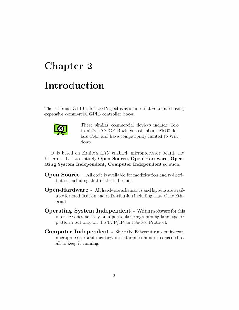
The Ethernut-GPIB Interface Project is as an alternative to purchasingexpensive commercial GPIB controller boxes.
These similar commercial devices include Tek-tronix’s LAN-GPIB which costs about $1600 dol-lars CND and have compatibility limited to Win-dows
It is based on Egnite’s LAN enabled, microprocessor board, theEthernut. It is an entirely Open-Source, Open-Hardware, Oper-ating System Independent, Computer Independent solution.
Open-Source - All code is available for modification and redistri-bution including that of the Ethernut.
Open-Hardware - All hardware schematics and layouts are avail-able for modification and redistribution including that of the Eth-ernut.
Operating System Independent - Writing software for thisinterface does not rely on a particular programming language orplatform but only on the TCP/IP and Socket Protocol.
Computer Independent - Since the Ethernut runs on its ownmicroprocessor and memory, no external computer is needed atall to keep it running.
3
2.1 Architecture Overview
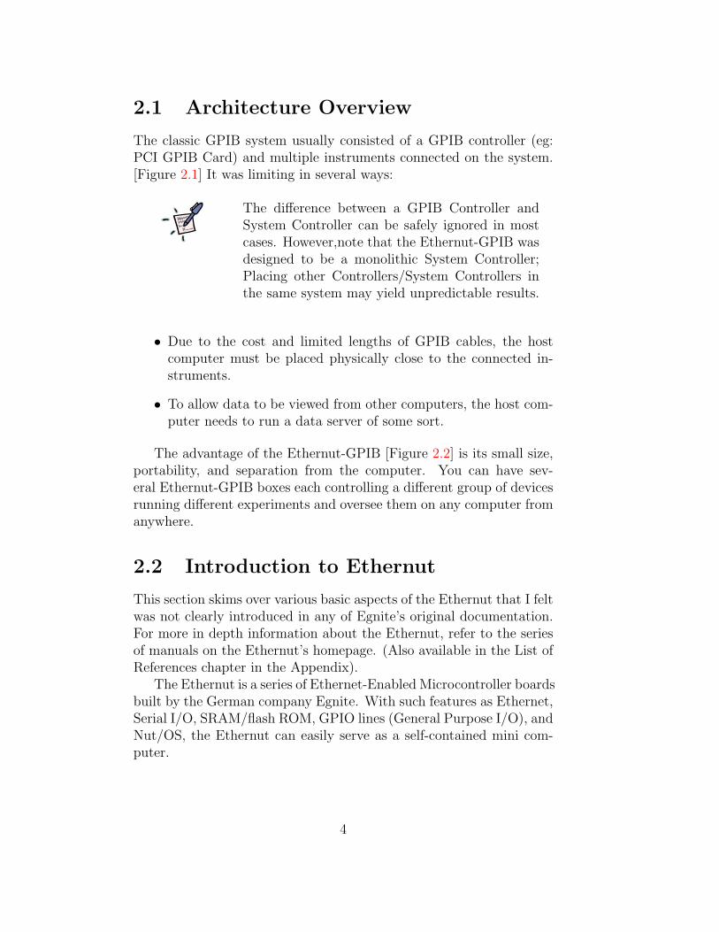
The classic GPIB system usually consisted of a GPIB controller (eg:PCI GPIB Card) and multiple instruments connected on the system.[Figure 2.1] It was limiting in several ways:
The difference between a GPIB Controller andSystem Controller can be safely ignored in mostcases. However,note that the Ethernut-GPIB wasdesigned to be a monolithic System Controller;Placing other Controllers/System Controllers inthe same system may yield unpredictable results.
• Due to the cost and limited lengths of GPIB cables, the hostcomputer must be placed physically close to the connected in-struments.
• To allow data to be viewed from other computers, the host com-puter needs to run a data server of some sort.
The advantage of the Ethernut-GPIB [Figure 2.2] is its small size,portability, and separation from the computer. You can have sev-eral Ethernut-GPIB boxes each controlling a different group of devicesrunning different experiments and oversee them on any computer fromanywhere.
2.2 Introduction to Ethernut
This section skims over various basic aspects of the Ethernut that I feltwas not clearly introduced in any of Egnite’s original documentation.For more in depth information about the Ethernut, refer to the seriesof manuals on the Ethernut’s homepage. (Also available in the List ofReferences chapter in the Appendix).
The Ethernut is a series of Ethernet-Enabled Microcontroller boardsbuilt by the German company Egnite. With such features as Ethernet,Serial I/O, SRAM/flash ROM, GPIO lines (General Purpose I/O), andNut/OS, the Ethernut can easily serve as a self-contained mini com-puter.
4

Figure 2.1: Classic GPIB Architecture from the NI7210 Manual
5

Figure 2.2: Ethernut-GPIB Architecture
The entire project was developed with the Ether-nut2.1. However, a new Ethernut3.0 is being de-veloped by Egnite using the ARM7 CPU. Its com-patibility with the current Ethernut-GPIB designis not known.
2.2.1 How Does the Ethernut Work?
It functions the same way as any computer:
1. Turn on Power
2. Begin Executing Instructions from Memory
3. Wait for User Input
4. Generate Output
The major difference is that the basic methods of input/output arenot your traditional keyboard/mouse/monitor but limited to Serialports, Ethernet and GPIO. The second notable difference is the types
6
of memory available on the Ethernut. Below is a brief description andcomparison.
There are 3 types of memory on the Ethernut:
Flash ROM For storing program code and read only data;analogous to a computer’s hard-disk.
SRAM Runtime memory; analogous to any kind of RAM in acomputer.
EEPROM For storing configuration data such as the MAC address;analogous to motherboard BIOS memory in a computer.
2.2.2 How Does Nut/OS Work?
The concept of operating system here is dramatically more primitivethan any OS we can find on a modern computer. When we think of anoperating system such as Windows or Linux, we might have a mislead-ing image of an OS simply being a program running on our computersproviding a basis of interaction between human and computer. How-ever, what is often overlooked is the operating system’s responsibilityof providing a programming interface to allow software control of thehardware. This is the essential duty of Nut/OS.
Counterintuitively, Nut/OS cannot ’run’ by itself on the Ethernut.Nut/OS is a collection of libraries written in AVR C. You need anapplication that implements these libraries to see Nut/OS in action.The simplest application possible on Nut/OS looks like this in AVRC.
#include <compiler.h>
int main(void) {
for (;;);
}
On the surface, this program runs in an endless loop doing noth-ing. However, since it included the directive, compiler.h, it is runningon along with Nut/OS background procedures as event handlers andtimers.
Furthermore, no real file system exists yet on Nut/OS. This meansthat there is no clear separation between operating system code (ker-nel) and application code, program instruction and data. You cannot
7
say, upload a new block of information onto the Ethernut’s memoryand ask Nut/OS to remember where it is, know how to retrieve it, ormodify it in a meaningful way. Thus, any structure about Nut/OSprogram, data or combination of these can only be modified exter-nally. And modification can be only be done as a whole. Everytimewe upload to the Ethernut, we are erasing its flash memoryentirely and rewriting Nut/OS.
What is AVR C? AVR C is a modified version ofC Language designed specifically for programmingAtmel’s line of AVR microcontrollers.
2.2.3 How Does the FileSystem Work?
We might ask, if there is no file system, then how is Nut/OS applica-tions capable of loading images and webpages etc? There is a mockfile system called ”UROM”. An application called ”crurom” can takea file and generate an array in C code containing the hex representa-tion of the file data. Thus, any required file data that we might needbecomes static variables in the program. Ie: below is the beginningof the converted data form of the Ethernut logo image; it goes on forseveral pages.
prog_char file1data[] = {
0x47,0x49,0x46,0x38,0x39,0x61,0xa8,0x00,0x39,0x00,0xf7,
0xff,0x00,0x00,0x00,0x00,0xc0,0xc0,0xc0,0xfe,0xfe,0xfe,
0xfd,0xfd,0xfd,0xfc,0xfc,0xfc,0xfa,0xfa,0xfa,0xf9,0xf9,
//...
}
8

Chapter 3
Tutorial
This is an quick start guide to using the Ethernut-GPIB including set-ting up the board, uploading the firmware and writing/compiling/runninga basic Ethernut-GPIB application in JavaTMon Windows and Linux.All the details here refer to EthernutV2.1 and ENUT-GPIBfirmware VR1.0. Since there is actually very little difference betweenthe Windows and Linux tutorial, I will not make a separate section foreach. My apologies to MAC users. I don’t know how to use one :-).
Windows specific details are in RedLinux specific sections are in Blue
3.1 Installing and Loading the Ethernut
If your Ethernut is new and isn’t already loaded with the ENUT-GPIB firmware, this section will take you through the steps of upload-ing it manually. If this is your first time, please follow throughthe ”Board Installation” tutorial in the Ethernut’s HardwareManual first.
What is firmware? Firmware is a low level pieceof software usually residing in flash memory of anembedded device. Here it refers to the softwaresitting on the Ethernut.
Before we can load our program onto the Ethernut, we need aninterface to transfer data from our computer. The Atmega128 (Ether-nut’s CPU) uses the JTAG interface (Joint Test Action Group) to loadprograms into its memory. The JTAG plug on the Ethernut is a 10
9

pin connector located beside the RS-485 screw terminal. The EthernutStarter Kit provides a Serial-JTAG/ISP programmer that connects tothe JTAG port on the Ethernut and a serial port on your computer.Due to the limited availability of serial ports on new computers, I usedUSB-Serial adapters instead. The problem with USB-Serial is thatthey come in so many brands and is difficult to find ones that havecompatible drivers with Linux.
Power on the Ethernut and Connect the Serial JTAG/ISPprogrammer to the Ethernut and the Computer; the greenpower LED should light up.
Note it doesn’t matter whether the GPIB con-troller board is attached or not during thisprocess. If you are using the Ethernut alone,it takes a 8-12V (˜400mA minimum) supply. Ifyou are using the Ethernut with the GPIB con-troller attached, the Ethernut will source powerfrom the GPIB board. The GPIB board requiresa 9V (˜600mA mimimum) power supply. DONOT attach power to both boards simul-taneously
The programmer provided by Egnite’s Starter Kituses the same connector for both JTAG and ISP(In System Programmin) interfaces. As warned inthe Ethernut’s Hardware Manual, NEVER plugthe ISP connector into Ethernut as it candamage the board. The best precaution is toeither tape it off or cut it off.
Next, we need a program to interface with the Serial-JTAG/ISPprogrammer. Download the Nut/OS package from Ethernut’shomepage and extract it. The tool we need is called ”UISP” and itsfound under the nut/tools/win32 or nut/tools/linux directory. Letsadd this directory to our system Path variable.
Under Windows XP, we can do this by going to Control Panel→System→Advanced→ Environment Variables and then appending the path(The Path of Ethernut Install)\nut\tools\win32 to the PATH variablewith a semi-colon separator.
Under Linux, we can edit local path variables by adding the line
10

PATH=$PATH:(The Path of Ethernut Install)/nut/tools/linux to .bash profilefile. If the line already exists, simply append the path to the end witha colon separator. To add the path to all users, we must have rootprivileges and append the path to etc/profile.
Now goto the directory with our precompiled firmware hex file,GPIB.hex and enter the following command. Make sure the serialport is connected and assigned to COM1.
uisp -dprog=stk500 -dserial=/dev/ttyS0 -dspeed=115200
-dpart=atmega128 --erase --upload if=GPIB.hex
What is a .hex file? A .hex file is the format thatAVR’s C compiler produces, a pure binary.
If we get a message like this:
Error: No such file or directory
-> /dev/ttyS0
make: *** [burn] Error 1
Then either the Serial-JTAG controller is not connected properly,or the serial port driver is not installed properly, or it is not assignedto serial port COM1. If the latter is the case, we can use any otherport we like by changing ttyS0 in the above command to ttySX whereis X-1 is COM port number.
If the procedure is successful, the Serial-JTAG LED will flash red/greenas it begins to write to memory.
Next, connect the Ethernut to the network and connectthe Ethernut’s serial port to the computer. (We can optionallydisconnect the serial cable used for the JTAG programmer.)
Now we need a terminal emulation program to communicate withthe Ethernut’s serial interface. For Windows, there is Hyperterminalor TeraTerm. For Linux, there is Minicom. Start the emulator withthe following settings:
baud: 38400
no parity
8 data bits + 1 stop bit
disable hardware flow control RTS/CTS
disable software flow control XON/XOFF
11

The Ethernut manual describes that the Ethernut’s serial interfaceis compatible with any speeds within 38400 and 115200 but for somereason I’ve never gotten it to work with rates other than 38400 so allthe baud rate variables written in my programs uses 38400 as well.
Hit the reset button on the Ethernut and we should see a messagein the terminal like this:
Ethernut-GPIB 1.1.21 Server Started
Initializing Drivers...
Server Configured with Address: 172.16.1.239
<<INIT SEQ COMPLETE>>
Using the serial terminal is basic method of determiningthe IP address of the Ethernut.
3.2 Talking GPIB
This section describes all the ways of communicating with a GPIB in-strument through the Ethernut-GPIB interface. However, this sectiondoes not explain the syntax of GPIB messages. Refer to GPIB tutori-als or instrument manuals (Some are available in the Appendix of thismanual). The GPIB.hex server program we just loaded in the previoussection is running two sets of server threads: one set serving webpageson Port 80 and the other is the main method of communication withGPIB instruments; running a custom-protocol server on Port 15000.We will refer to this as the GPIB-Server throughout this document.
A ”thread” in computer science is a task that canshare resources and run simultaneously with othertasks within a program
3.2.1 SSH Tunneling
If the Ethernut is connected on a local network (like on QDG) and wewant to access it from a outside computer, the easiest way is to create aSSH Tunnel [Figure 3.1] (provided that the server computer is runningan SSH server). This mini tutorial uses the example of connectingto an Ethernut’s GPIB-Server (address 172.16.1.239:15000) inside thenetwork hosted by the server computer QDG.
12

Figure 3.1: SSH Tunnel
13
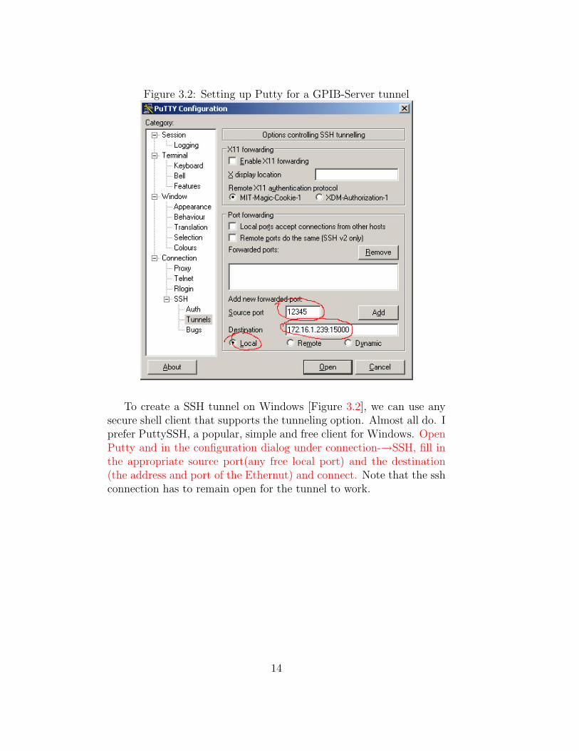
Figure 3.2: Setting up Putty for a GPIB-Server tunnel
To create a SSH tunnel on Windows [Figure 3.2], we can use anysecure shell client that supports the tunneling option. Almost all do. Iprefer PuttySSH, a popular, simple and free client for Windows. OpenPutty and in the configuration dialog under connection-→SSH, fill inthe appropriate source port(any free local port) and the destination(the address and port of the Ethernut) and connect. Note that the sshconnection has to remain open for the tunnel to work.
14
To create a SSH tunnel on linux, simply use the -L option with thessh command.
[-L port:host:hostport]
eg:
ssh qdg.physics.ubc.ca -L 12345:172.16.1.239:15000
This simply tells ssh to connect to the server qdg.physics.ubc.ca butat the same time forward our local port 12345 to the subnet address172.16.1.239:15000. Note that the ssh connection has to remain openfor the tunnel to work.
Now that we created the tunnel, the address localhost:(the tunnelport) becomes equivalent to 172.16.1.239:15000 if we were on a com-puter sitting inside the qdg network.
3.2.2 Connecting to an Instrument
The simplest way to see the Ethernut-GPIB in action is to open up ourfavourite web browser, hopefully Firefox ;-), and type in the addressof the Ethernut. Click on the GPIB Demo link and it will take usto a form that allows us to send commands to the GPIB instrumentconnected to GPIB Address 1. Connect a GPIB instrument, such asthe Tektronix scope, to the Ethernut-GPIB and set it to Address 1.Try typing GPIB messages to it.
There is no internal mechanism for GPIB instru-ments to detect address conflicts. If two deviceshave the same address, and we try to query thataddress for example, they will both try to talkback simultaneously, resulting in a convoluted re-sponse.
15
What is GPIB Address? It is a unique num-ber assigned to each GPIB instrument in the sys-tem. Usually, the controller will have address 0and the rest is arbitrary. GPIB Addresses canonly be changed physically on the instrument, notthrough software. Most systems are limited to 15instrument but 31 addresses are available.
Simply type in any command and the program will try to obtaina response from the instrument. Of course, only query commands willgenerate a response.
Due to the limited memory available on the Eth-ernut, the servers are set to allow very limitednumber of connections simultaneously. For exam-ple, currently 4 is limit for the GPIB-Server.
Using the browser, we connected to the Ethernut-GPIB’s webserveron Port 80. Now we can try connecting to the GPIB-Server on Port15000.
As an example, we can use telnet to do this. Telnet [Figure 3.3] isa classic TCP/IP command line protocol and program for sending rawtext messages over the network. Telnet is almost exactly the same onWindows and Linux, with the basic format that looks like this.
telnet [host] [port]
On the GPIB-Server, we can type messages to the GPIB instrumentexactly the same way as in the browser. The only difference is that wecan send Ethernut-GPIB commands.
3.2.3 Ethernut-GPIB Commands
Ethernut-GPIB Commands are a special type of message understoodonly by the Ethernut-GPIB. They allow the user to communicate withthe either the Ethernut itself, or the GPIB controller board, as opposedto GPIB instruments. The rules are simple:
- Ethernut-GPIB commands begin with the ’!’ character
- Ethernut-GPIB commands are always in capital letters
- All other messages are treated as GPIB messages and sent to the
instrument directly.
16

Figure 3.3: Telnet to the GPIB-Server
Do not confuse ’Ethernut-GPIB commands’ with’GPIB commands’. GPIB commands are a set ofcommands that all GPIB instruments must under-stand, as specified by IEEE488.2. They are alsoreferred to as ’Multiline Command Messages’.
For example, use the !SETIADDR command to change the ref-erence GPIB address, allowing us to communicate with multiple in-struments. [Figure 3.3] When we sent GPIB messages previously, wehave been sending them to the default address, 1. However, to talkto a different address, we need to change the reference address. Ie:!SETIADDR 19
Another command is !QUIT, this will simply disconnect us fromthe server. (We can also disconnect by sending an empty line) For alist of all Ethernut-GPIB commands, refer to the Appendix.
3.3 Writing a Simple Program
This section is a step by step tutorial on writing/compiling/running asimple program in Java that can communicate with a GPIB instrumentthrough the Ethernut-GPIB interface.
17
Why Java? Java is simple, clean and cross-platform.
3.3.1 Getting Java
All the resources mentioned here can be downloaded at java.sun.com.The sample code and sample program is available in the Appendix. Ifwe goto the downloads section and select the latest version, (I used1.5.0 for these examples) there will be several packages to select from.Here is what we need.
JRE Java Runtime Environment, required to run java programs
SDK Software Development Kit, required to compile and build javaprograms, already includes the JRE.
Netbeans an IDE (Integrated Development Environment), this tuto-rial will not cover how to use Netbeans, but most of it is self-explanatory after installing.
So we only need to download and install the SDK package. OnWindows, this is pretty straightforward. On Linux, the procedure isslightly different depending on the distribution. There are very helpfulinstallation instructions on the downloads page, so they will not becovered here.
A quick check to see if at least the JRE is installed:
java -version
3.3.2 Sockets
This section gives some brief theory of Sockets. This knowledge is notrequired to be able to program with Sockets but nonetheless is usefulinformation.
The concept of sockets is an universal idea in computer networking,not limited to Java. A socket simply consists of variables that containsthe IP address and port of the server/client that we are connecting to.A socket is a type of header for a packet, which is a representationfor groups of data being transferred over the network. As a real worldexample, consider a packet as a lettermail, and a socket as the part ofthe postage label containing the recipient’s address.
So what is IP address and Port? An IP (Internet Protocol) addressis a number that identifies a computer on a network (a LAN, WAN,
18

or the entire Internet). The most common type of IP address weencounter is in the form of uuu.uuu.uuu.uuu in decimal or xx:xx:xx:xxin hexadecimal. This is referred to an IPv4 address. The IPv4 protocolallows for 232 addresses. IPv6, an expanded address protocol thatallows for 2128 addresses, is slowly replacing IPv4.
The IPv4 address is divided into several ranges, or classes. Thefollowing tables illustrates some important classes and subclasses.
Table 3.1: Major IP ClassesClass Begin End Number of Networks Number of Addresses
A 10.0.0.0 127.255.255.255 128 16,777,214B 128.0.0.0 191.255.255.255 16,384 65,534C 192.0.0.0 223.255.255.255 2,097,152 256
The class divisions are assigned to accommodate different sizednetworks. As we can see from [Table 3.1], the Number of Networks inan address range increases as the Number of Addresses increase. Butthe purpose of these kind of divisions is not apparent. However, outthis concept developed ’netmasks’, in which smaller ranges of addresswithin these classes are used to create small private networks. [Table3.2]
Table 3.2: Familiar Classes of SubnetsSubClass of Begin End Number of Addresses
A 10.0.0.0 10.255.255.255 16,777,216B 172.16.0.0 172.31.255.255 1,048,576C 192.168.0.0 192.168.255.255 65,536
For example, by convention, seeing a computer with an IP addressof 192.168.xxx.xxx will instantly tell us the following information:
-The computer is part of a small network of < 65536 members
19
-The computer does not have an exclusive IP address outside of
this small network.
This allows each non-private IP address to host a network as largeas 16,777,216 computers. However, each computer must be ’routed’through the non-private address to access the rest of the Internet.
On a smaller scale, this concept of multiplexing a single IP intomany is exactly the idea of ’ports’. A port is a 16-bit integer repre-senting the communication between a client to a host over a uniqueprocess or program. Without ports, a computer with one networkcard would only be able to run a single network program at a time.Many common ports will often identify its program. For example, apacket header containing port 80 will tell us that the protocol of trans-fer is http and a web-browser was most likely involved in sending thispacket.
In Socket Programming, we will be dealing with the concepts ofcreating the socket (writing the address and making the package), con-necting the socket (checking to see if the recipient exists), and writ-ing/reading from the socket.
3.3.3 The Code
This section dives right into writing code in Java. If (OOP) Object-Oriented Programming or Java is new to you, thats okay, most of thecode shown here will be very procedural and understandable. But itsnever a bad idea to go through some basic Java tutorials on java.sun.com.
The purpose of this program is to connect to a Tektronix (3000series) scope and grab some graph data from it.
Source files used in this example (available in the appendix):
• Main.java
• EGInterface.java
EGInterface.java is a class that encapsulates some basic func-tions for communicating with the Ethernut-GPIB through sockets. Wecan use this file as a starting point for most GPIB programs.
20
What is class and object? A class is the funda-mental concept of Object-Oriented Programming.It is a template that lets the programmer designcustom variables, or objects. Think of a class asa cookie-cutter and the object as the cookie. Wemold the cookie-cutter into whatever shape once,then we can easily bake thousands of look-alikecookies. Yum.
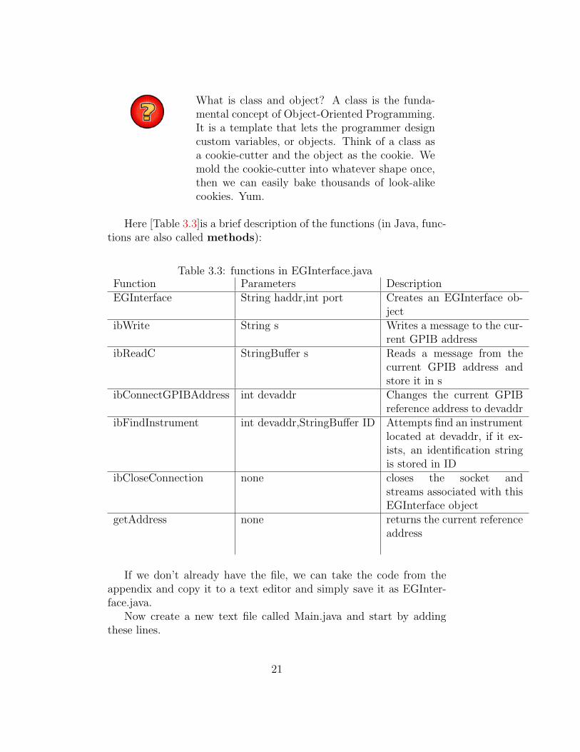
Here [Table 3.3]is a brief description of the functions (in Java, func-tions are also called methods):
Table 3.3: functions in EGInterface.javaFunction Parameters DescriptionEGInterface String haddr,int port Creates an EGInterface ob-
jectibWrite String s Writes a message to the cur-
rent GPIB addressibReadC StringBuffer s Reads a message from the
current GPIB address andstore it in s
ibConnectGPIBAddress int devaddr Changes the current GPIBreference address to devaddr
ibFindInstrument int devaddr,StringBuffer ID Attempts find an instrumentlocated at devaddr, if it ex-ists, an identification stringis stored in ID
ibCloseConnection none closes the socket andstreams associated with thisEGInterface object
getAddress none returns the current referenceaddress
If we don’t already have the file, we can take the code from theappendix and copy it to a text editor and simply save it as EGInter-face.java.
Now create a new text file called Main.java and start by addingthese lines.
21

public class Main {
public static void main(String[] args) {
}
}
This is the starting point for execution in a Java program. Eventhough the Main class here serves no purpose, Java requires that ALLinstructions in a program be encapsulated in a class, unlike C or otherprocedural languages.
Next we want to read the IP address and the port of Ethernut-GPIB from the command line. Add this code into main.
if(args.length!=2) {
System.err.println("Invalid Arguments");
return;
}
String IP = args[0];
int port = Integer.parseInt(args[1]);
Now we want to create a socket and connect to the Ethernut-GPIBon the given IP and port.
EGInterface eg = new EGInterface(IP,port);
Next, lets connect to address 1. Make sure the scope is physicallyconnected properly and its GPIB address set to 1.
To set the scope’s address, we need to gotoutility→System I/O→I/O→GPIB Talk/Listen→Talk/Listen Address and twiddle the knob besidethe ”select” and ”coarse” buttons.
eg.ibConnectGPIBAddress(1);
Notice that when a function is part of a class (such as EGInter-face) ,we need to use the ”dot notation” and say eg.myfunction(param1,param 2); as opposed to simply myfunction(param 1,param 2).
Next, lets write a couple of GPIB commands that tells the scopeto send us a waveform. These commands are specific to the Tektronixscopes and we can check the Tektronix Scope manual to see what theymean in detail.
22

eg.ibWrite("DATA:SOURCE CH1");
eg.ibWrite("DATA:ENCDG ASCII");
eg.ibWrite("DATA:START 1");
eg.ibWrite("DATA:STOP 500");
eg.ibWrite("CURVE?");
Note this will only grab 500 points from the current graph. If wewant the entire graph, we need to either set ”DATA:STOP” to 10000points or decrease the resolution to 500 points.
Next, lets read the response and print it out.
StringBuffer s = new StringBuffer();
eg.ibRead(s);
System.out.println("The Response is: " + s);
and finally, close the connection.
eg.ibCloseConnection();
Save this file as Main.java and make sure its in the same directoryas EGInterface.java.
3.3.4 Compiling and Running
To compile, we will use the javac program. For the system to knowwhere to find javac, we need to make sure the path jdk1.5.0 04\binis in the system path. This is done in the same way as we addedthe Ethernut’s tools folder to the system path in the ”Installing andLoading” section of the tutorial.
Compiling is the same for all platforms. Goto the directory of yoursource file and type.
javac Main.java
This will compile both Main.java and EGInterface.java as the Javacompiler is smart enough to automatically recognize the dependency.After the compile is complete (assuming no error messages), javac willgenerate two new files: Main.class and EGInterface.class. .class filesare to the Java Virtual Machine as executable binaries are to our com-puters.
Now to test our program giving it an IP and port.
java Main [Ethernut’s IP] 15000
23

We should get something like this.
The Response is:
-34,-33,-32,-33,-32,-33,-33,-32,-33,-32,-33,-32,-32,-33,-32,-32
......
24
Chapter 4
Hardware
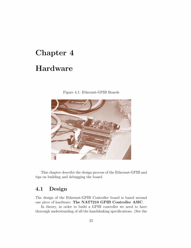
Figure 4.1: Ethernut-GPIB Boards
This chapter describe the design process of the Ethernut-GPIB andtips on building and debugging the board.
4.1 Design
The design of the Ethernut-GPIB Controller board is based aroundone piece of hardware: The NAT7210 GPIB Controller ASIC.
In theory, in order to build a GPIB controller we need to havethorough understanding of all the handshaking specifications. (See the
25

GPIB tutorial available in the Appendix) But since we live in an ageof cheap reusable silicon technology, the NAT7210 ASIC (ApplicationSpecific Integrated Circuit) takes care of all the details for us.
The 7210 is actually an older model chip for GPIBcontrollers but fully satisfies our purposes. Neweroptions include the 9914 or TNT series
4.1.1 NAT7210
Figure 4.2: The NAT7210 ASIC
This section summarize the functionalities of NAT7210 and focuson how it applies to the Ethernut-GPIB design. For an elaboratedescription of the chip itself, refer to the NAT7210 Manual (availablein the Appendix).
The NAT7210 is a 40pin programmable IC designed to performall the functions of IEEE 488.2 (GPIB) specifications. It is packagedwith a 8 bit data bus and a 3-bit address bus and designed to becontrolled by a CPU. The 7210 does not communicate directly withGPIB instruments but through 2 specific transceiver chips. [Figure 4.3]This is actually a common GPIB instrument design in the industry.
[Figure 4.3] shows the NAT7210 connected to the 75160 and 75162transceiver chips which then connects to a standard GPIB cable. Onemight question the purpose of the chips upon seeing that most of thelines seems to go in from one side and directly out on the other. Thesetransceiver chips serve two main purposes:
• Allows bidirectional data flow
• Buffers signal strength to meet IEEE488 specifications
26
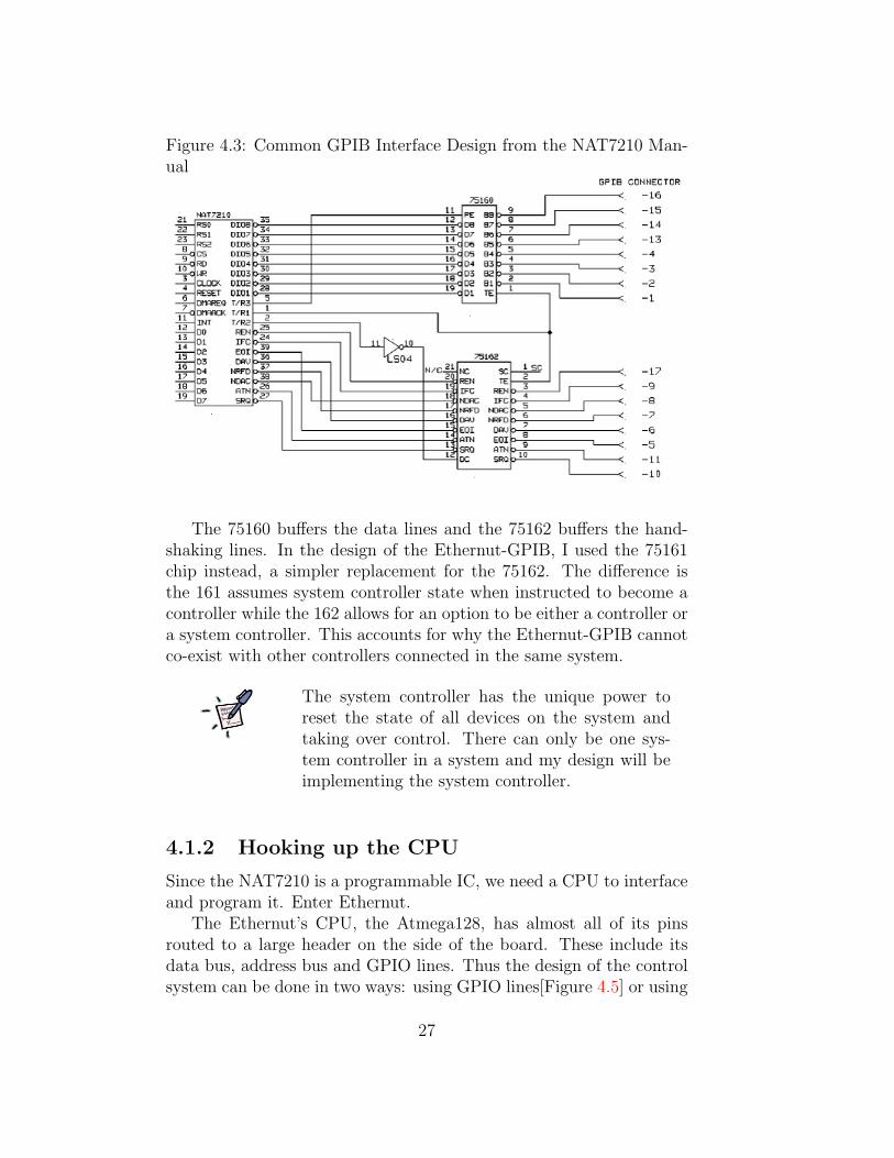
Figure 4.3: Common GPIB Interface Design from the NAT7210 Man-ual
The 75160 buffers the data lines and the 75162 buffers the hand-shaking lines. In the design of the Ethernut-GPIB, I used the 75161chip instead, a simpler replacement for the 75162. The difference isthe 161 assumes system controller state when instructed to become acontroller while the 162 allows for an option to be either a controller ora system controller. This accounts for why the Ethernut-GPIB cannotco-exist with other controllers connected in the same system.
The system controller has the unique power toreset the state of all devices on the system andtaking over control. There can only be one sys-tem controller in a system and my design will beimplementing the system controller.
4.1.2 Hooking up the CPU
Since the NAT7210 is a programmable IC, we need a CPU to interfaceand program it. Enter Ethernut.
The Ethernut’s CPU, the Atmega128, has almost all of its pinsrouted to a large header on the side of the board. These include itsdata bus, address bus and GPIO lines. Thus the design of the controlsystem can be done in two ways: using GPIO lines[Figure 4.5] or using
27

Figure 4.4: The Original Ethernut-GPIB TestBoard
Memory-Mapped I/O with the Atmega128’s data/address bus. Thefirst method I used in the testing stages [Figure 4.4] while the latterour electronic shop implemented in the finished product.
What is Memory-Mapped I/O? MMIO refersto the technique of the CPU directly address-ing/writing to a peripheral device by treating itas an address in memory. This is demonstratedlater in the Software section.
[Table 4.1] compares these methods.
Table 4.1: Pros and Cons of GPIO and MMIOPro Con
GPIO - Easy to debug, full control of all lines - Slower- Requires no hardware logic - More work to program
MMIO - Requires logic analyzers to debug since bus is shared - Faster- Requires multiplexing between data/address buses - Easy to program
Since MMIO is a cleaner solution and a standard concept of com-puter science, it was adopted in the end. The GPIO method wasconsidered as a viable solution too because the Ethernut-GPIB was asmall scale application and GPIB is a very slow protocol to begin with.
28
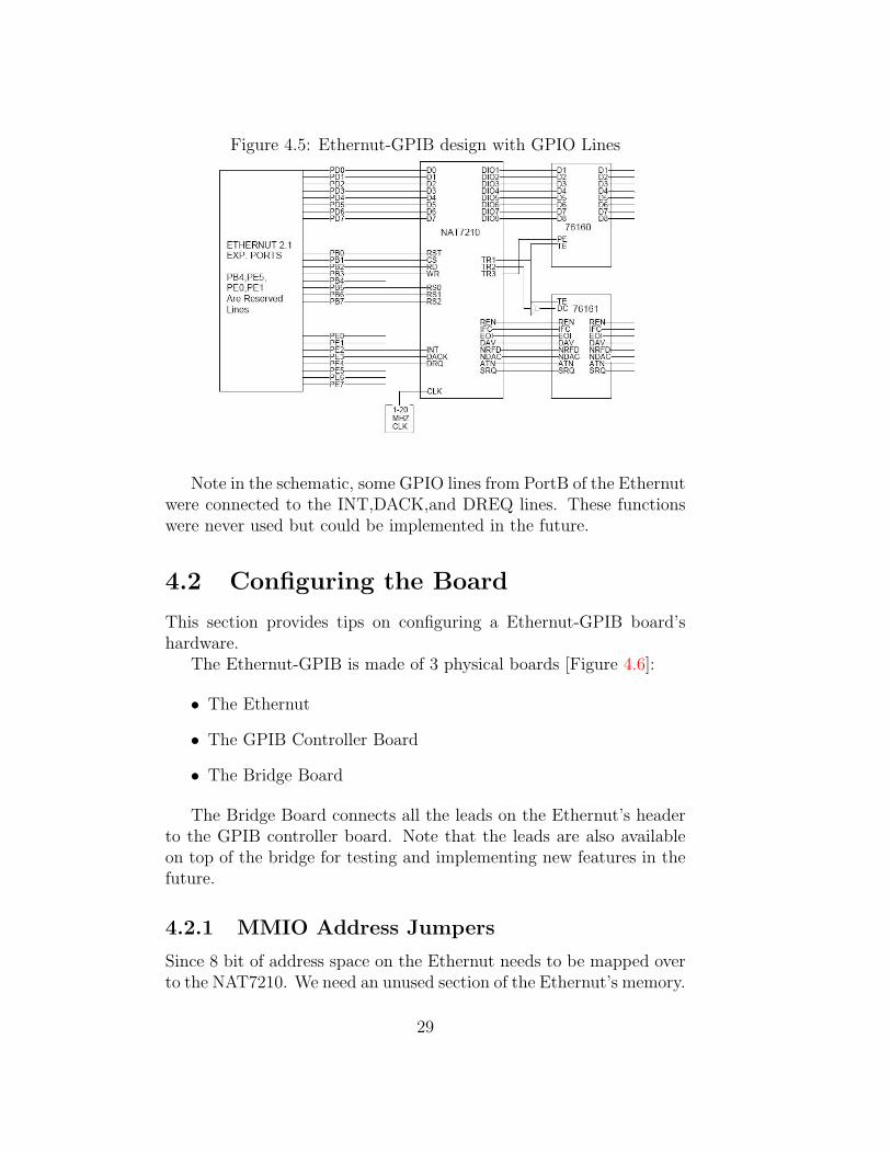
Figure 4.5: Ethernut-GPIB design with GPIO Lines
Note in the schematic, some GPIO lines from PortB of the Ethernutwere connected to the INT,DACK,and DREQ lines. These functionswere never used but could be implemented in the future.
4.2 Configuring the Board
This section provides tips on configuring a Ethernut-GPIB board’shardware.
The Ethernut-GPIB is made of 3 physical boards [Figure 4.6]:
• The Ethernut
• The GPIB Controller Board
• The Bridge Board
The Bridge Board connects all the leads on the Ethernut’s headerto the GPIB controller board. Note that the leads are also availableon top of the bridge for testing and implementing new features in thefuture.
4.2.1 MMIO Address Jumpers
Since 8 bit of address space on the Ethernut needs to be mapped overto the NAT7210. We need an unused section of the Ethernut’s memory.
29
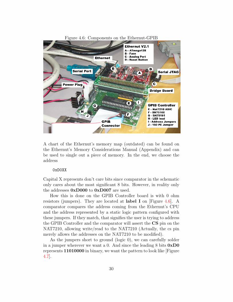
Figure 4.6: Components on the Ethernut-GPIB
A chart of the Ethernut’s memory map (outdated) can be found onthe Ethernut’s Memory Considerations Manual (Appendix) and canbe used to single out a piece of memory. In the end, we choose theaddress
0xD0XX
Capital X represents don’t care bits since comparator in the schematiconly cares about the most significant 8 bits. However, in reality onlythe addresses 0xD000 to 0xD007 are used.
How this is done on the GPIB Controller board is with 0 ohmresistors (jumpers). They are located at label I on [Figure 4.6]. Acomparator compares the address coming from the Ethernut’s CPUand the address represented by a static logic pattern configured withthese jumpers. If they match, that signifies the user is trying to addressthe GPIB Controller and the comparator will assert the CS pin on theNAT7210, allowing write/read to the NAT7210 (Actually, the cs pinmerely allows the addresses on the NAT7210 to be modified).
As the jumpers short to ground (logic 0), we can carefully solderin a jumper wherever we want a 0. And since the leading 8 bits 0xD0represents 11010000 in binary, we want the pattern to look like [Figure4.7].
30

Figure 4.7: Filling the MMIO Address Jumpers
4.2.2 Other Jumpers
Besides the MMIO address jumpers, there are 2 other jumpers on thecurrent version of the GPIB Controller board.
One is fairly obvious and that is the power LED lead at label Hon [Figure 4.6].
The other is the Pullup-Enable jumper for the 75160 chip locatedat label J on [Figure 4.6]. This jumper decides whether the Pullup-Enable function (Refer to the 75160 data sheet) is controlled on board(shorted to ground) or by the NAT7210 (can be programmed). In mostcases, this should be controlled by the NAT7210 but as PE is almostalways pulled low, shorting the jumper gives the option of keeping itlow.
4.3 Troubleshooting
The section describes known hardware problems with Ethernut-GPIBand should be kept open to additions. On way to resolve hardware
31
problems is to subscribe and write to egnite’s discussion mailing list.(I’ve already subscribed for qdg for the qdg physics account)
4.3.1 Ethernut Fuse
Symptoms:
The Ethernut blew up. The Ethernut died. The Ethernut is not
powering.
Known Solutions:
There is a fuse on the Ethernut located at label B on [Figure
\ref{components}] rated to blow at 1Amp but also protects against
overvoltage by a selfdestructing mechanism when the voltage across
shoots over 18 V. This problem concerns using the Ethernut
\textbf{without} the GPIB Controller board. (The Ethernut fuse is
bypassed since power is supplied from the GPIB Controller board).
The problem was that the Ethernut doesn’t come with a power supply
(not even the starter kit) and only specified that it requires an
input voltage between 8 and 12V. So we simply hoisted the nearest
radio shack 12V DC adapter and plugged in. Long and behold it works.
But occasionally it would blow the fuse because the standard power
supply sends noisy voltage spikes at instant you plug it in. We
measured the spikes on the scope and read levels up to 20 or 30 V,
which surely would have blown the fuse. The solution was filter the
power supply with one of the regulator circuits that Janelle Dongen
built. It provided voltage regulation at a stable 12V and filters
out RF noise with ferrite beads. The fuses are replaceable and
manufacture by Littlefuse with catalog number 0453 001.
32

Chapter 5
Software
The chapter describes the design of the software architecture for theEthernut-GPIB as well provide information on writing programs forthe Ethernut in AVR C. These sections assume some previousknowledge of writing programs in C.
5.1 Software Architecture
The main aim of the Ethernut-GPIB software was to ensure portability.If someone decides that they like writing programs for one particularoperating system, that is up to them. But it should be equally assimple for another person to write the same program for another OS.
The key to accomplishing this is using simple network protocols.For example, the GPIB server running on the Ethernut takes raw mes-sages coming from the user and passes them onto the GPIB instrumentverbatim. The concept is that all we need to know is how to use sock-ets and we can write programs in any language on any platform wewant. Note in [Figure 5.1] there is a different ”socket API” for everyprogramming language but the concept is universal.
5.2 The Firmware
This section describes some of the important components in the Ethernut-GPIB’s firmware (software on board the Ethernut) and how they work.
Here is a list of the files and their purposes in source code of thefirmware. [Table 5.1]
Since there are no classes in C language, here is the pretend hierar-chy chart of the Ethernut-GPIB firmware. [Figure 5.2] The dependen-
33

Figure 5.1: Ethernut-GPIB Software Architecture
cies of the files doesn’t look exactly like this but it outlines the idea Ihad in mind when designing.The next few subsections describe some of these modules in top downfashion.
5.2.1 Start of Execution
File: GPIBENUTKERNEL.c
Here the main function does several things:
• Initialize Ethernut Devices (LAN/Serial)
• Initialize the NAT7210
34
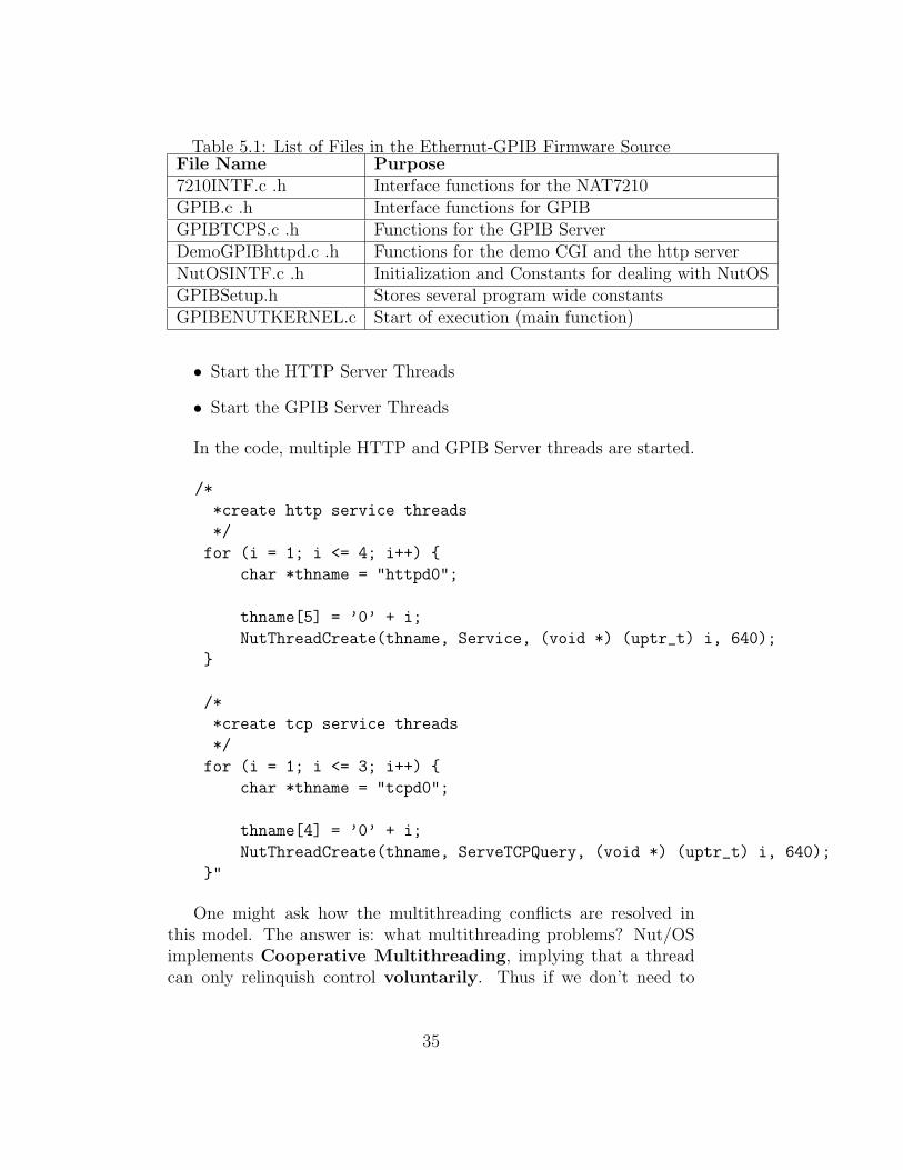
Table 5.1: List of Files in the Ethernut-GPIB Firmware SourceFile Name Purpose7210INTF.c .h Interface functions for the NAT7210GPIB.c .h Interface functions for GPIBGPIBTCPS.c .h Functions for the GPIB ServerDemoGPIBhttpd.c .h Functions for the demo CGI and the http serverNutOSINTF.c .h Initialization and Constants for dealing with NutOSGPIBSetup.h Stores several program wide constantsGPIBENUTKERNEL.c Start of execution (main function)
• Start the HTTP Server Threads
• Start the GPIB Server Threads
In the code, multiple HTTP and GPIB Server threads are started.
/*
*create http service threads
*/
for (i = 1; i <= 4; i++) {
char *thname = "httpd0";
thname[5] = ’0’ + i;
NutThreadCreate(thname, Service, (void *) (uptr_t) i, 640);
}
/*
*create tcp service threads
*/
for (i = 1; i <= 3; i++) {
char *thname = "tcpd0";
thname[4] = ’0’ + i;
NutThreadCreate(thname, ServeTCPQuery, (void *) (uptr_t) i, 640);
}"
One might ask how the multithreading conflicts are resolved inthis model. The answer is: what multithreading problems? Nut/OSimplements Cooperative Multithreading, implying that a threadcan only relinquish control voluntarily. Thus if we don’t need to
35

Figure 5.2: Ethernut-GPIB Firmware
worry about resource sharing,locks,semaphores and other PreemptiveMultithreading concepts.
What is Cooperative Multithreading? It is anold and simple approach to multithreading wherethreads can only voluntarily relinquish control. Itis simple to implement but can run into problemsvery easily as the OS becomes more complicated.Now it is still used in many embedded applicationssuch as the Ethernut.
5.2.2 GPIB Server
Files: GPIBTCPS.c GPIBTCPS.h
The GPIB Server uses Nut/OS TCP Socket API to create a serversocket listening on port 15000 for connections and uses socket I/O
36
streams to read and write data. It is important to note that data isreceived via the fgets() function.
fgets(buff, bufsize, instream);
fgets() is an old age C function that reads a single line of textfrom a file pointer. Due to this fact, all clients MUST terminatetheir messages with a newline characters. Otherwise, fgets() willblock and wait for the end of the line. When program our clients, wemust be aware that newlines are not the same on all operating systems.It is not sufficiently fool proof to use the C newline character ’\n’.A standard symbol CRLF should be used instead. This a CarriageReturn character followed immediately by a Linefeed character. Whenprogramming, the correct control sequence to use is:
"\x0D\x0A"
Note this is not always equivalent to:
\r\n
Message Processing
The GPIB Server sends all messages (anything that doesn’t begin witha ! character) to its message processor function. The message proces-sor basically passes off the message to the GPIB device,tries reads aresponse, and sends it back.Since the Ethernut has limited memory, some GPIB responses (such aswaveforms) are unreasonably large to store on the Ethernut even tem-porarily. Thus all the response data are streamed back to the client indiscrete packets of 254 bytes. The server then terminates its responseswith CRLF:
fprintf_P(outstream, PSTR("\x0D\x0A"));
Command Processing
The GPIB Server’s command processor is designed to take inputs offorms similar to unix commands. Ie: [Command] [-options] [ar-guments] It is also written to be flexible for implementing new com-mands. To add a new command XYZ, follow these steps:
37

A - Add a new command ID Add a new command identifier XYZto the enumeration string in GPIBTCPS.h.
enum {VERSION,SETIADDR,RESET,WRITE7210,READ7210,SENDCTRLCMD,XYZ};
B - Add the command string to comparator There is a list ofif statements in the beginning of the ProcessCommand function inGPIBTCPS.c. Their purpose is to match a string to a command.And a new else statement like this:
\\...
else if(strcmp(strupr(r),"XYZ")==0) {
newCommand.commandName = XYZ;
}
\\...
C - Add a new command handler There is a case statement thathandles commands near the end of the ProcessCommand functionin GPIBTCPS.c. Add a new case for the new command:
case XYZ:
//do something here
return;
break;
The commands options and parameters are stored in the newCom-mand structure. Its definition is in GPIBTCPS.h.
Note the command handlers could use separate functions, but sincethere aren’t many commands at this point, the case statement is sim-pler.
5.2.3 GPIB Interface Functions
Files: GPIB.c GPIB.h
The GPIB interface functions are all low level functions designedto communicate directly with the NAT7210. Thus most of these func-tions here involve register level programming, writing and reading in-teger values to registers, so understanding the code requires familiaritywith the NAT7210 reference manual. However, below describes someimportant features
38

Init Sequence
The initialization sequence for the NAT7210 is in the Init Sequencefunction. This function is called in the main function in GPIBE-NUTKERNEL.c. It contains calls to a set of macros defined inGPIB.h. These macros reflect the step by step initialization sequencedocumented in chapter 5 of the NAT7210 manual. Some of these stepsin the sequence may need to be modified to accommodate changes inhardware. For example, two macros in combination define the systemclock speed to be 20mhz, if the speed is ever changed, these macrosneed to be changed as well.
#define SET_ICR Write_7210(0x2A,5) //20mhz
#define SET_ICR2 Write_7210(0x50,5);Write_7210(0x81,3)
Timeout Constant
There is a timeout constant in GPIB.h, currently set to 10000.
#define TIMEOUT 10000
Many GPIB handshaking operations require some form of acknowl-edgement signal upon completion or failure. The NAT7210 does thisby toggling certain bits in the registers. Thus in the code we needloops to constantly check for the status of these bits before and/or af-ter certain operations. This timeout feature is implemented to keep theprogram from running into an infinite loop when an instrument is notresponding for whatever reason. However, some operations take longerthan others as GPIB is very slow, thus this timeout constant may needto be adjusted when implementing new GPIB interface functions.
5.2.4 NAT7210 and MMIO Programming
Files: 7210INTF.c 7210INTF.h
Being on the lowest point on the program hierarchy, the 7210 in-terface functions are actually the simplest. In face, it only comprisesreading and writing using memory-mapped IO.
//This is writing with MMIO
volatile unsigned int* p = (unsigned int*) (ADDR_OFFSET + addr);
*p = byte;
//This is reading with MMIO
volatile unsigned int* p = (unsigned int*) (ADDR_OFFSET + addr);
*byte = *p;
39
What is a volatile variable? The volatile keywordimplies that the value of a variable will NOTbe cached in the cpu registers for any reason.Caching in the registers allows for fast arithmeticoperations, but this isn’t what we want for MMIO.If we are writing to a memory-mapped location,we want that the value be written directly to thatlocation.
5.3 Building with Nut/OS
This section outlines how to install, build and compile programs underNut/OS
The first order of business is to install the Nut/OS package. It isalways best to download the latest version from the Ethernut’s Site.However, beware of the difference in versions. Many new changes areintroduced in each new version and may become inconsistent with de-tails in this manual. I used 3.9.5 but the latest available version as ofnow is 3.9.8. Luckily, all versions are available on Ethernut’s homepageand their CVS repository.To be able to compile programs with Nut/OS, we need to first buildthe libraries. The Nut/OS configurator is a nice graphical interface forselecting various options for different builds. Instructions for installingand building the Nut/OS package are available in the Ethernut’s Soft-ware Manual.
5.3.1 Using AVR C Makefiles
The makefiles for AVR C look exactly the same as conventional make-files for C. However, there are several common targets specific to build-ing Ethernut and/or AVR C programs.
Burn is the name of a target that uses the uisp program to uploadapplications to the Ethernut.
Webfile is the name of a target that uses the crurom program tocreate the ’urom’ source files from conventional webfiles such as htmldocuments or images.
40
Program is the name of a target used by makefiles under theWinAVR environment to upload applications with the avrdude pro-gram. This is equivalent of uisp.
The easiest way to create a makefile for Nut/OS programs is toplace our project folder under our build directory for Nut/OS and thensimply include the Makedefs and Makerules that came with Nut/OS.
include ../Makedefs
include ../Makerules
Now we can use some of the definitions such as $(LIBDIR) or$(SRCS:.c=.o).
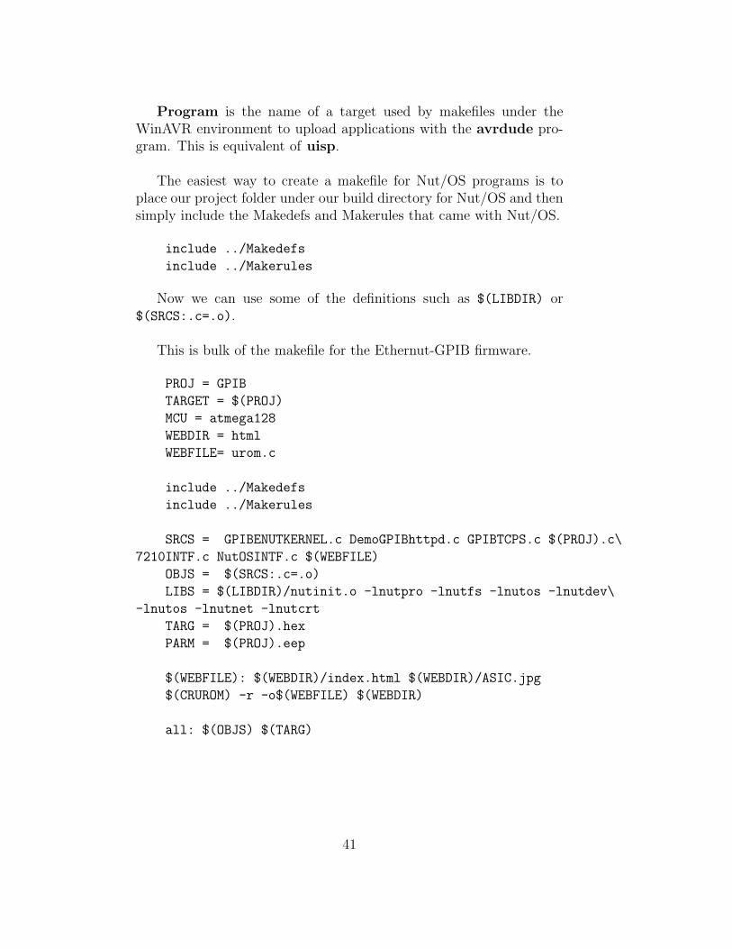
This is bulk of the makefile for the Ethernut-GPIB firmware.
PROJ = GPIB
TARGET = $(PROJ)
MCU = atmega128
WEBDIR = html
WEBFILE= urom.c
include ../Makedefs
include ../Makerules
SRCS = GPIBENUTKERNEL.c DemoGPIBhttpd.c GPIBTCPS.c $(PROJ).c\
7210INTF.c NutOSINTF.c $(WEBFILE)
OBJS = $(SRCS:.c=.o)
LIBS = $(LIBDIR)/nutinit.o -lnutpro -lnutfs -lnutos -lnutdev\
-lnutos -lnutnet -lnutcrt
TARG = $(PROJ).hex
PARM = $(PROJ).eep
$(WEBFILE): $(WEBDIR)/index.html $(WEBDIR)/ASIC.jpg
$(CRUROM) -r -o$(WEBFILE) $(WEBDIR)
all: $(OBJS) $(TARG)
41
5.4 Tips for Embedded Coding
This section will describe some important differences between writingnormal C code and embedded C code and guidelines for writing moreefficient code. The reference manuals Nut/OS Memory Consid-erations and Nut/OS Threads, Events, and Timers have muchmore elaborate information. Please read these as well if you wish tooptimize your programs.
5.4.1 Embedded Programs: Where does it end?
Unlike normal programs for computers, embedded programs can’t end.For example, consider the hello world program in C:
int main(void) {
printf("Hello World!");
return 0;
}
On a computer, this program will simply print hello world and exitwhen it reaches ’return 0’, which tells the operating system that theprogram is finished and safe to release its memory.On a microcontroller such as the Atmega128, the result of this programis catastrophe: might as well call it ’Goodbye World’ instead.The problem here is that what happens after the CPU has reachedthe end of its instructions is unknown and is inconsistent from onemicrocontroller to another. The Atmega128 has a Watchdog Timerto prevent fatal system crashes due to unterminated code.
What is a Watchdog Timer? A Watchdog Timeris a common failsafe system placed on microcon-trollers. It is simply a timer that will reset theentire system if it runs down to 0. Thus embed-ded compilers must always include instructions to”pet the dog” (reset the timer) at appropriate in-stances to keep it from exploding.
The simple solution to avoid this is to ALWAYS put an infiniteloop at the end of our programs.
int main(void) {
42

printf("Hello World from the Atmega128!");
while(1);
}
5.4.2 Using Flash ROM
Conserving memory is a large issue in embedded programming, muchlike normal programming when computers had 128k of RAM 15 yearsago. The Ethernut provides 512k of Flash ROM (in addition to theAtmega128’s 128k Flash ROM) to allow larger programs. However thismemory could also be used for storing static variables and long stringsof text. (As opposed to storing them in SRAM at runtime).
AVR-GCC recognizes special a special keyword for this purpose:prog char.
For example, storing html code for CGI is waste of SRAM, but wecan force it into Flash ROM like this:
static prog_char head[] =
"<HTML><HEAD><TITLE>Parameters</TITLE></HEAD><BODY><H1>Parameters</H1>";
Additionally, avr libc provides an extra set of functions ending in _P
as well as the macro PSTR() for putting static variables into flashrom.(Consult the avr libc manual for more details).
For example:
fprintf_P(outstream, PSTR("x Invalid Parameters\n"));
is much more conservative than:
fprintf(outstream, "x Invalid Parameters\n");
5.4.3 Heap or Garbage Pile?
The Ethernut’s software manual recommends extensive use of heapmemory. I think this point is important enough to be commented on.(Please read the section called ’Heap Management’ in the EthernutSoftware Manual)This refers to dynamically allocating memory using malloc and calloc
43
as opposed to declaring local variables. The Ethernut’s manual men-tions wasting memory by declaring local variables in threads. However,since the stack size for a thread is pre-allocated to a fix size, we arenot doing any harm by creating more local variables if the sum of thelocal variable sizes is well within this limit.Additionally, there is a conservative and wasteful way of dynami-cally allocating memory in threads. Consider this snippet from theEthernut-GPIB’s server thread:
THREAD(ServeTCPQuery,arg) {
//...
NutTcpAccept(sock, TCP_PORT);
//...
long bufsize = 255;
char* buff;
if( (buff = calloc(bufsize,sizeof(char))) == NULL)
printf("Out of Memory\n");
//...
}
The server thread blocks at the NutTcpAccept function and waitsfor connections. After a user connects, it will allocate a piece of heapmemory for its main stream buffer. Imagine if this allocation was donebefore the blocking call. Then the server will sit there with this hugechunk of memory already allocated doing nothing. Multiply the sizeof that buffer by the number of threads running and we have a wastedblock of memory equivalent to declaring the buffer as a local variable.The counter-argument is that allocating a heap at the beginning isfaster. This is true but it is up to the programmer to decide whetherspeed or memory is more important. The moral of the story is:heaps aren’t trivial either, think before you allocate them.
5.5 Troubleshooting
This section will document known software bugs and their solutions.The best way to solve software problems with AVR C programming isread/post on the forums of AVRFreaks.net. There is a large com-munity of AVR programmers (and freaks) there to help.
5.5.1 Unresponsive DHCP client
Symptoms:
44
Ethernut programs to refuse to obtain IP addresses assigned by the
DHCP server. But when we checked the server logs, there appears to
be corrupt packets coming from the Ethernut.
Known Solution:
Unfortunately, I still can’t conclude on this problem but it is most
likely a hardware problem with the LAN IC possibly caused by
ESD(electro static discharge). We ended up replacing the board.
5.5.2 Floating Point Variables
Symptoms:
Floating point related variables doesn’t work.
Known Solution:
Nut/OS does not need floating points and by default is not built to
use them. You need to enable floating points in the configurator and
rebuild Nut/OS. There is a tutorial on this on the Ethernut’s
homepage under ’documents’.
45

Chapter 6
To Do List
This section describes Ethernut-GPIB related projects that are unfin-ished or not started. This chapter should be updated along as theseprojects progress.
6.1 The Box
The rack mount container for the Ethernut-GPIB is an unfinishedproject currently being worked on by the UBC Electronic Shop. Ihave no details at this point.
6.2 The Software
The GPIB Interface does not fully satisfy all the functions of a normalGPIB controller. Ie: it cannot perform parallel and serial polls. Thesefunctions should be implemented in GPIB.c and GPIB.h in the sourcefile as needed.Also, the Ethernut-GPIB command set can be expanded to accommo-date more functionality as needed.
6.3 The Wiki
This is a future project to start a wiki webpage for the Ethernut-GPIBdepending on its popularity. The idea is to collect all the programsand libraries that people has written for the Ethernut-GPIB and tohave them available online.
46
Appendix A
List of References
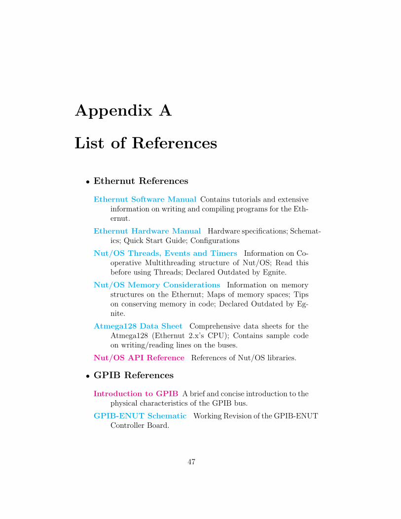
• Ethernut References
Ethernut Software Manual Contains tutorials and extensiveinformation on writing and compiling programs for the Eth-ernut.
Ethernut Hardware Manual Hardware specifications; Schemat-ics; Quick Start Guide; Configurations
Nut/OS Threads, Events and Timers Information on Co-operative Multithreading structure of Nut/OS; Read thisbefore using Threads; Declared Outdated by Egnite.
Nut/OS Memory Considerations Information on memorystructures on the Ethernut; Maps of memory spaces; Tipson conserving memory in code; Declared Outdated by Eg-nite.
Atmega128 Data Sheet Comprehensive data sheets for theAtmega128 (Ethernut 2.x’s CPU); Contains sample codeon writing/reading lines on the buses.
Nut/OS API Reference References of Nut/OS libraries.
• GPIB References
Introduction to GPIB A brief and concise introduction to thephysical characteristics of the GPIB bus.
GPIB-ENUT Schematic Working Revision of the GPIB-ENUTController Board.
47
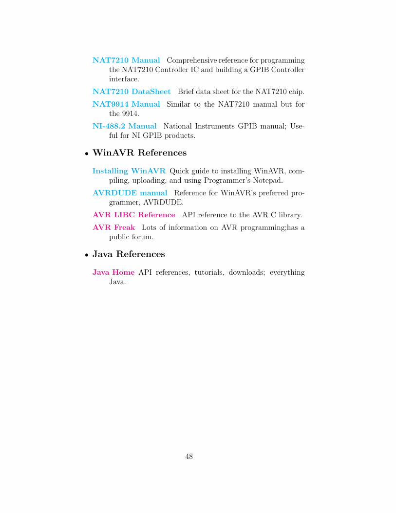
NAT7210 Manual Comprehensive reference for programmingthe NAT7210 Controller IC and building a GPIB Controllerinterface.
NAT7210 DataSheet Brief data sheet for the NAT7210 chip.
NAT9914 Manual Similar to the NAT7210 manual but forthe 9914.
NI-488.2 Manual National Instruments GPIB manual; Use-ful for NI GPIB products.
• WinAVR References
Installing WinAVR Quick guide to installing WinAVR, com-piling, uploading, and using Programmer’s Notepad.
AVRDUDE manual Reference for WinAVR’s preferred pro-grammer, AVRDUDE.
AVR LIBC Reference API reference to the AVR C library.
AVR Freak Lots of information on AVR programming;has apublic forum.
• Java References
Java Home API references, tutorials, downloads; everythingJava.
48
Appendix B
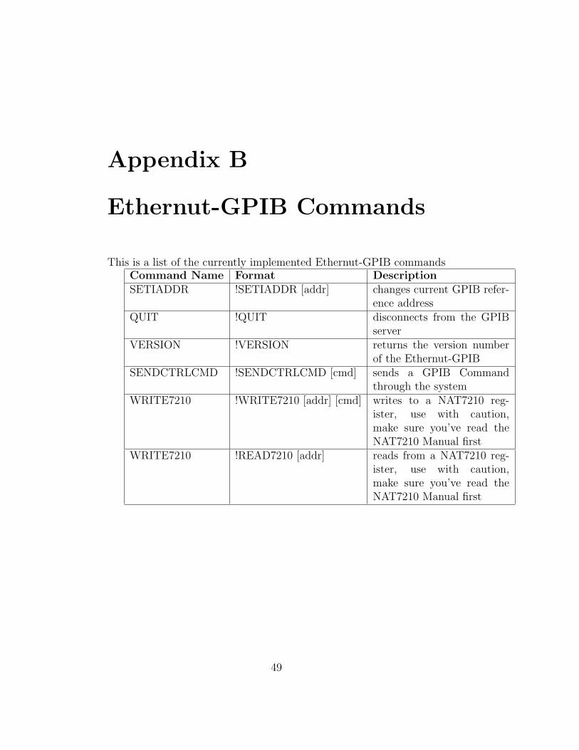
Ethernut-GPIB Commands
This is a list of the currently implemented Ethernut-GPIB commandsCommand Name Format DescriptionSETIADDR !SETIADDR [addr] changes current GPIB refer-
ence addressQUIT !QUIT disconnects from the GPIB
serverVERSION !VERSION returns the version number
of the Ethernut-GPIBSENDCTRLCMD !SENDCTRLCMD [cmd] sends a GPIB Command
through the systemWRITE7210 !WRITE7210 [addr] [cmd] writes to a NAT7210 reg-
ister, use with caution,make sure you’ve read theNAT7210 Manual first
WRITE7210 !READ7210 [addr] reads from a NAT7210 reg-ister, use with caution,make sure you’ve read theNAT7210 Manual first
49
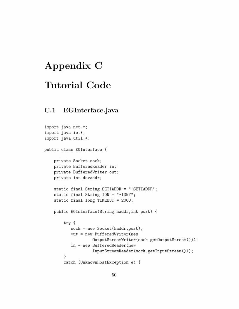
Appendix C
Tutorial Code
C.1 EGInterface.java
import java.net.*;
import java.io.*;
import java.util.*;
public class EGInterface {
private Socket sock;
private BufferedReader in;
private BufferedWriter out;
private int devaddr;
static final String SETIADDR = "!SETIADDR";
static final String IDN = "*IDN?";
static final long TIMEOUT = 2000;
public EGInterface(String haddr,int port) {
try {
sock = new Socket(haddr,port);
out = new BufferedWriter(new
OutputStreamWriter(sock.getOutputStream()));
in = new BufferedReader(new
InputStreamReader(sock.getInputStream()));
}
catch (UnknownHostException e) {
50

System.err.println("Trying to connect to unknown host: " + e);
}
catch (IOException e) {
System.err.println("IOException: " + e);
}
}
int getAddress() {
return this.devaddr;
}
int ibWrite(String s) {
if(!sock.isConnected()) {
System.err.println("Socket is not connected");
return -1;
}
try {
out.write(s,0,s.length());
out.newLine();
out.flush();
} catch (IOException e) {
System.err.println("IOException: " + e);
}
return 0;
}
int ibRead(StringBuffer s) {
if(!sock.isConnected()) {
System.err.println("Socket is not connected");
return -1;
}
try {
51
Date d = new Date();
long time = d.getTime();
while (!in.ready()) {
if( (new Date().getTime()-time) > TIMEOUT) {
System.err.println("Timed Out Waiting for Response");
return -1;
}
}
String t;
while( (t = in.readLine()).compareTo("")==0 );
s = s.insert(0,t);
} catch (IOException e) {
System.err.println("IOException: " + e);
}
return 0;
}
int ibConnectGPIBAddress(int devaddr) {
if(!sock.isConnected()) {
System.err.println("Socket is not connected");
return -1;
}
if(devaddr<0 || devaddr>31) {
System.err.println("Invalid Address Range");
return -1;
}
try {
Date d = new Date();
String s = new String(SETIADDR + " " + devaddr);
out.write(s,0,s.length());
out.newLine();
out.flush();
52

String responseLine;
long time = d.getTime();
while (!in.ready()) {
if( (new Date().getTime()-time) > TIMEOUT) {
System.err.println("Timed Out Waiting for Response");
return -1;
}
}
responseLine = in.readLine();
if(responseLine.charAt(0)==’x’) {
System.err.println("Error Trying to Change GPIB Address");
return -1;
}
} catch (IOException e) {
System.err.println("IOException: " + e);
}
this.devaddr = devaddr;
return 0;
}
int ibFindInstrument(int devaddr,StringBuffer ID) {
int tempAddr = this.devaddr;
if(this.ibConnectGPIBAddress(devaddr)!=0) {
System.err.println("Unable to Connect");
return -1;
}
try {
Date d = new Date();
out.write(IDN,0,IDN.length());
out.newLine();
out.flush();
long time = d.getTime();
while (!in.ready()) {
53
if( (new Date().getTime()-time) > TIMEOUT) {
System.err.println("Timed Out Waiting for Response");
return -1;
}
}
ID = ID.insert(0,in.readLine());
} catch (IOException e) {
System.err.println("IOException: " + e);
}
if(this.ibConnectGPIBAddress(tempAddr)!=0) {
System.err.println("Unable to Connect");
return -1;
}
return 0;
}
void ibCloseConnection() {
try {
out.close();
in.close();
sock.close();
} catch (UnknownHostException e) {
System.err.println("Trying to connect to unknown host: " + e);
} catch (IOException e) {
System.err.println("IOException: " + e);
}
}
}
C.2 Main.java
public class Main {
public static void main(String[] args) {
54
if(args.length!=2) {
System.err.println("Invalid Arguments");
return;
}
String IP = args[0];
int port = Integer.parseInt(args[1]);
EGInterface eg = new EGInterface(IP,port);
eg.ibConnectGPIBAddress(1);
StringBuffer s = new StringBuffer();
eg.ibWrite("DATA:SOURCE CH1");
eg.ibWrite("DATA:ENCDG ASCII");
eg.ibWrite("DATA:START 1");
eg.ibWrite("DATA:STOP 500");
eg.ibWrite("CURVE?");
eg.ibRead(s);
System.out.println("The Response is: " + s);
eg.ibCloseConnection();
}
}
55

Bibliography
[7210MANUAL] National Instruments Corporation, NAT7210 Refer-ence Manual June 1995 Edition,1994
[Ethernut] egnite Software GmbH, Ethernut: Embedded Ether-net,http://www.ethernut.de/,http://www.egnite.de/
[ENsoftware] egnite Software GmbH, Ethernut Software Manual:Manual Revision: 2.0,2004
[ENHardware] egnite Software GmbH, Ethernut Version 2.1 Hard-ware User‘s Manual: Manual Revision: 1.1,2004
[ENMem] Harald Kipp, Nut/OS Memory Considerations,2004,egnite Software GmbH
[HTTPserver] egnite Software GmbH, httpserv.c,2004
[WINAVR] Colin O’Flynn, Editor: Eric Weddington, Download-ing, Installing and Configuring WinAVR,2004
56


