Report No.: BSL008390302RF Page 2 of 44 FCC Part 15.247
TABLE OF CONTENTS1. GENERAL INFORMATION....................................................................................................................................31.1 PRODUCT DESCRIPTION FOR EQUIPMENT UNDER TEST (EUT).............................................................................. 31.2 EUT SETUP AND TESTMODE.................................................................................................................................51.3 TEST STANDARDS................................................................................................................................................... 51.4 TESTMETHODOLOGY............................................................................................................................................. 51.5 TEST FACILITY........................................................................................................................................................ 51.6 MEASUREMENT UNCERTAINTY...............................................................................................................................61.7 TEST EQUIPMENT LIST AND DETAILS.....................................................................................................................6
2. SUMMARY OF TEST RESULTS............................................................................................................................ 7
3. RF EXPOSURE.......................................................................................................................................................... 83.1 STANDARD APPLICABLE......................................................................................................................................... 83.2 TEST RESULT.......................................................................................................................................................... 8
4. ANTENNA REQUIREMENT................................................................................................................................... 94.1 STANDARD APPLICABLE......................................................................................................................................... 94.2 EVALUATION INFORMATION................................................................................................................................... 9
11. PSEUDORANDOM FREQUENCY HOPPING SEQUENCE...........................................................................25
12. BAND EDGE...........................................................................................................................................................26
15. TEST SETUP PHOTO...........................................................................................................................................43
Report No.: BSL008390302RF Page 3 of 44 FCC Part 15.247
1. GENERAL INFORMATION
1.1 Product Description for Equipment Under Test (EUT)
Applicant: LOWEX, LLC
Address of applicant: 739 NW 105th Pl, Miami, Florida 33172, USA
Manufacturer: LuZhou XinYu Communication Technology Co., LTD
Address of manufacturer: NO.19, Section 5, JiuGu Avenue, High Tech District, LuZhou City,SiChuan Provice, China
Product Name: feature phone
Model No.: F18
Test Model No: F18
Remark: All above models are identical in the same PCB layout, interior structure and electrical circuits. Thedifferences are color, appearance and model name for commercial purpose.
Quantity of tested samples 1
Serial No.: N/A
Description test modes: SIM 1 and SIM 2 is a chipset unit,the wors case is SIM1.
Hardware Version: DF600_PCB
Software Version: DF600_DF600E_HC
Operation Frequency: 2402MHz~2480MHz
Channel numbers: 79
Channel separation: 1MHz
Modulation type: GFSK, Pi/4 QPSK, 8DPSK
Antenna Type: Internal antenna
Antenna gain: 1.2dBi
Power supply: DC 3.7V by battery or DC 5V from adapter input AC 120V, 60Hz
BSL Testing Co.,LTD. Report No.: BSL008390306RF
Report No.: BSL008390302RF Page 4 of 44 FCC Part 15.247
Operation Frequency each of channel
Channel Frequency Channel Frequency Channel Frequency Channel Frequency
1 2402MHz 21 2422MHz 41 2442MHz 61 2462MHz
2 2403MHz 22 2423MHz 42 2443MHz 62 2463MHz
3 2404MHz 23 2424MHz 43 2444MHz 63 2464MHz
4 2405MHz 24 2425MHz 44 2445MHz 64 2465MHz
5 2406MHz 25 2426MHz 45 2446MHz 65 2466MHz
6 2407MHz 26 2427MHz 46 2447MHz 66 2467MHz
7 2408MHz 27 2428MHz 47 2448MHz 67 2468MHz
8 2409MHz 28 2429MHz 48 2449MHz 68 2469MHz
9 2410MHz 29 2430MHz 49 2450MHz 69 2470MHz
10 2411MHz 30 2431MHz 50 2451MHz 70 2471MHz
11 2412MHz 31 2432MHz 51 2452MHz 71 2472MHz
12 2413MHz 32 2433MHz 52 2453MHz 72 2473MHz
13 2414MHz 33 2434MHz 53 2454MHz 73 2474MHz
14 2415MHz 34 2435MHz 54 2455MHz 74 2475MHz
15 2416MHz 35 2436MHz 55 2456MHz 75 2476MHz
16 2417MHz 36 2437MHz 56 2457MHz 76 2477MHz
17 2418MHz 37 2438MHz 57 2458MHz 77 2478MHz
18 2419MHz 38 2439MHz 58 2459MHz 78 2479MHz
19 2420MHz 39 2440MHz 59 2460MHz 79 2480MHz
20 2421MHz 40 2441MHz 60 2461MHz
Note:
In section 15.31(m), regards to the operating frequency range over 10 MHz, the Lowest frequency, the middlefrequency, and the highest frequency of channel were selected to perform the test.
EUT Cable List and DetailsCable Description Length (M) Shielded/Unshielded With Core/Without Core
Earphone 1.0 Unshielded Without Ferrite
Auxiliary Equipment List and DetailsDescription Manufacturer Model Serial NumberAdapter JINFULIN A01 /
Special Cable List and DetailsCable Description Length (M) Shielded/Unshielded With Core/Without Core
/ / / /
BSL Testing Co.,LTD. Report No.: BSL008390306RF
Report No.: BSL008390302RF Page 5 of 44 FCC Part 15.247
1.2 EUT Setup and Test Mode
The EUT was operated in the engineering mode to fix the Tx frequency that was for the purpose of themeasurements. All testing shall be performed under maximum output power condition, and to measure its highestpossible emissions level.
Test Mode ListTest Mode Description Channel Frequency (MHz)
1 GFSK,CH1 2402CH40 2441CH79 2480
2 Pi/4 QPSKCH1 2402CH40 2441CH79 2480
3 8DPSKCH1 2402CH40 2441CH79 2480
1.3 Test Standards
The following report accordance with FCC Part 15, Subpart C, and section 15.203, 15.205, 15.207, 15.209 and15.247 of the Federal Communication Commissions rules.
1.4 Test Methodology
All measurements contained in this report were conducted with ANSI C63.10-2013, American National Standardfor Testing Unlicensed Wireless Devices, and ANSI C63.4-2014, American National Standard for Methods ofMeasurement of Radio-Noise Emissions from Low-Voltage Electrical and Electronic Equipment in the range of 9kHz to 40 GHz.
Report No.: BSL008390302RF Page 7 of 44 FCC Part 15.247
2. SUMMARYOFTEST RESULTS
Test Item Section in CFR 47 Result
RF Exposure (SAR)Part 1.1307
Part 2.1093
Pass*
(Please refer to
SAR Report)
Antenna Requirement 15.203/15.247 (c) Pass
AC Power Line ConductedEmission
15.207 Pass
Conducted Peak OutputPower
15.247 (b)(1) Pass
20dB Occupied Bandwidth 15.247 (a)(1) Pass
Carrier FrequenciesSeparation
15.247 (a)(1) Pass
Hopping Channel Number 15.247 (a)(1) Pass
Dwell Time 15.247 (a)(1) Pass
Pseudorandom FrequencyHopping Sequence
15.247(b)(4) Pass
Radiated Emission 15.205/15.209 Pass
Band Edge 15.247(d) Pass
Pass: The EUT complies with the essential requirements in the standard.
Remark: Test according to ANSI C63.10:2013
BSL Testing Co.,LTD. Report No.: BSL008390306RF
Report No.: BSL008390302RF Page 8 of 44 FCC Part 15.247
3. RF Exposure
3.1 Standard Applicable
According to§1.1307 and §2.1093, the portable transmitter must comply the RF exposure requirements.
3.2 Test Result
This product complied with the requirement of the RF exposure, please see the RF Exposure Report.
BSL Testing Co.,LTD. Report No.: BSL008390306RF
Report No.: BSL008390302RF Page 9 of 44 FCC Part 15.247
4. Antenna Requirement
4.1 Standard Applicable
According to FCC Part 15.203, an intentional radiator shall be designed to ensure that no antenna other than thatfurnished by the responsible party shall be used with the device. The use of a permanently attached antenna or ofan antenna that uses a unique coupling to the intentional radiator shall be considered sufficient to comply with theprovisions of this section.
4.2 Evaluation Information
This product has a internal permanent antenna(1.2dBi), fulfill the requirement of this section.
BSL Testing Co.,LTD. Report No.: BSL008390306RF
Report No.: BSL008390302RF Page 10 of 44 FCC Part 15.247
Quasi-peak Average0.15-0.5 66 to 56* 56 to 46*0.5-5 56 465-30 60 50
* Decreases with the logarithm of the frequency.
Test setup:
Test procedure: 1. The E.U.T and simulators are connected to the main power through aline impedance stabilization network (L.I.S.N.). This provides a50ohm/50uH coupling impedance for the measuring equipment.
2. The peripheral devices are also connected to the main power through aLISN that provides a 50ohm/50uH coupling impedance with 50ohmtermination. (Please refer to the block diagram of the test setup andphotographs).
3. Both sides of A.C. line are checked for maximum conductedinterference. In order to find the maximum emission, the relativepositions of equipment and all of the interface cables must be changedaccording to ANSI C63.10:2013 on conducted measurement.
Test Instruments: Refer to section 1.7 for details
Test mode: Refer to section 1.2 for details
Test results: Pass
BSL Testing Co.,LTD. Report No.: BSL008390306RF
Report No.: BSL008390302RF Page 11 of 44 FCC Part 15.247
Measurement data:Line:
BSL Testing Co.,LTD. Report No.: BSL008390306RF
Report No.: BSL008390302RF Page 12 of 44 FCC Part 15.247
Neutral:
BSL Testing Co.,LTD. Report No.: BSL008390306RF
Report No.: BSL008390302RF Page 13 of 44 FCC Part 15.247
6. Conducted Peak Output Power
Test Requirement: FCC Part15 C Section 15.247 (b)(3)
Test Method: ANSI C63.10:2013
Limit: 30dBm(for GFSK),20.97dBm(for EDR)
Test setup:
Test Instruments: Refer to section 1.7 for details
Test mode: Refer to section 1.2 for details
Test results: Pass
Measurement Data
Mode Test channelPeak Output Power
(dBm)Limit (dBm) Result
GFSK
Lowest 0.065
30.00 PassMiddle 0.652
Highest 0.958
Pi/4QPSK
Lowest -0.956
20.97 PassMiddle 0.068
Highest 0.095
8DPSK
Lowest -0.358
20.97 PassMiddle 0.352
Highest 0.245
BSL Testing Co.,LTD. Report No.: BSL008390306RF
Report No.: BSL008390302RF Page 14 of 44 FCC Part 15.247
7. 20dB Emission Bandwidth
Test Requirement: FCC Part15 C Section 15.247 (a)(2)
Test Method: ANSI C63.10:2013
Limit: N/A
Test setup:
Test Instruments: Refer to section 1.7 for details
Test mode: Refer to section 1.2 for details
Test results: Pass
Measurement Data
Mode Test channel20dB Emission Bandwidth
(MHz)Result
GFSK
Lowest 0.93
PassMiddle 0.93
Highest 0.93
Pi/4QPSK
Lowest 1.29
PassMiddle 1.29
Highest 1.28
8DPSK
Lowest 1.28
PassMiddle 1.28
Highest 1.28
BSL Testing Co.,LTD. Report No.: BSL008390306RF
Report No.: BSL008390302RF Page 15 of 44 FCC Part 15.247
Test plot as follows:
Test mode: GFSK mode
Lowest channel
Middle channel
Highest channel
BSL Testing Co.,LTD. Report No.: BSL008390306RF
Report No.: BSL008390302RF Page 16 of 44 FCC Part 15.247
Test mode: Pi/4QPSK mode
Lowest channel
Middle channel
Highest channel
BSL Testing Co.,LTD. Report No.: BSL008390306RF
Report No.: BSL008390302RF Page 17 of 44 FCC Part 15.247
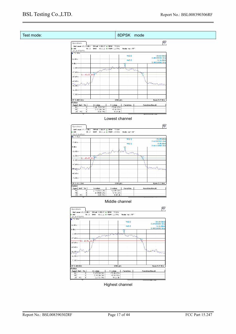
Test mode: 8DPSK mode
Lowest channel
Middle channel
Highest channel
BSL Testing Co.,LTD. Report No.: BSL008390306RF
Report No.: BSL008390302RF Page 18 of 44 FCC Part 15.247
8. Carrier Frequencies Separation
Test Requirement: FCC Part15 C Section 15.247 (a)(1)
Limit: 0.025MHz or 2/3 of the 20dB bandwidth (whichever is greater)
Test setup:
Test Instruments: Refer to section 1.7 for details
Test mode: Refer to section 1.2 for details
Test results: Pass
Measurement Data
Modulation type ChannelCarrier FrequenciesSeparation (MHz)
Limit (MHz) * Result
GFSK 39 1.00 ≥0.93 Pass
π/4DQPSK 39 1.00 ≥0.86 Pass
8DPSK 39 1.00 ≥0.85 Pass
Note:*: GFSK limit = The maximum 20 dB Bandwidth for GFSK modulation on the section 7.4.π/4DQPSK limit = 2/3 * The maximum 20 dB Bandwidth for π/4DQPSK modulation on the section 7.4.8DPSK limit = 2/3 * The maximum 20 dB Bandwidth for 8DPSK modulation on the section 7.4
BSL Testing Co.,LTD. Report No.: BSL008390306RF
Report No.: BSL008390302RF Page 19 of 44 FCC Part 15.247
Test plot as follows:Only show the worst case
GFSK
π/4DQPSK
8DPSK
BSL Testing Co.,LTD. Report No.: BSL008390306RF
Report No.: BSL008390302RF Page 20 of 44 FCC Part 15.247
9. Hopping Channel Number
Test Requirement: FCC Part15 C Section 15.247 (a)(1)
Test Method: ANSI C63.10:2013
Receiver setup: RBW=100kHz, VBW=300kHz, Frequency range=2400MHz-2483.5MHz,Detector=Peak
Limit: 15 channels
Test setup:
Test Instruments: Refer to section 1.7 for details
Test mode: Refer to section 1.2 for details
Test results: Pass
Measurement Data:
Mode Hopping channel numbers Limit Result
GFSK 79 15 Pass
Pi/4QPSK 79 15 Pass
8DPSK 79 15 Pass
BSL Testing Co.,LTD. Report No.: BSL008390306RF
Report No.: BSL008390302RF Page 21 of 44 FCC Part 15.247
GFSK
π/4DQPSK
8DPSK
BSL Testing Co.,LTD. Report No.: BSL008390306RF
Report No.: BSL008390302RF Page 22 of 44 FCC Part 15.247
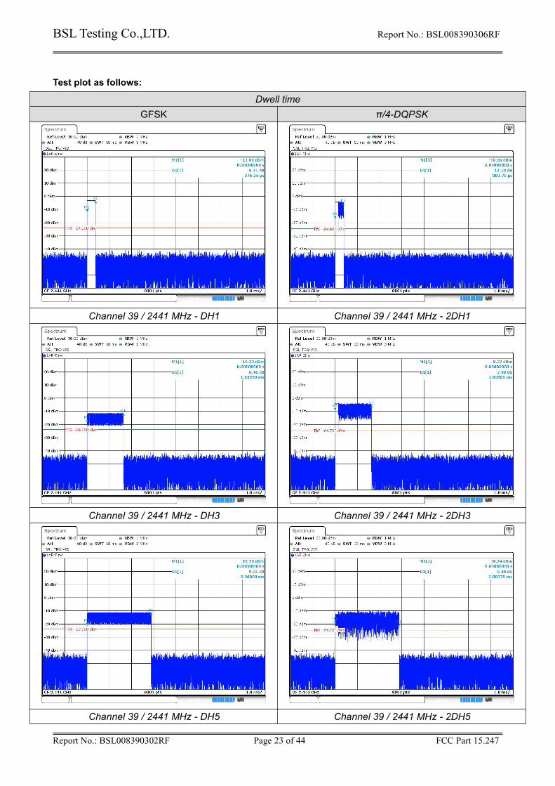
10. Dwell Time
Test Requirement: FCC Part15 C Section 15.247 (a)(1)
Report No.: BSL008390302RF Page 24 of 44 FCC Part 15.247
Dwell time8DPSK
Channel 39 / 2441 MHz - 3DH1
2 Channel 39 / 2441 MHz - 3DH3
Channel 39 / 2441 MHz - 3DH5
BSL Testing Co.,LTD. Report No.: BSL008390306RF
Report No.: BSL008390302RF Page 25 of 44 FCC Part 15.247
11. Pseudorandom Frequency Hopping Sequence
Test Requirement: FCC Part15 C Section 15.247 (a)(1) requirement:
Frequency hopping systems shall have hopping channel carrier frequencies separated by a minimum of25 kHz or the 20 dB bandwidth of the hopping channel, whichever is greater.
Alternatively. Frequency hopping systems operating in the 2400-2483.5 MHz band may have hoppingchannel carrier frequencies that are separated by 25 kHz or two-thirds of the 20 dB bandwidth of thehopping channel, whichever is greater, provided the systems operate with an output power no greaterthan 125 mW. The system shall hop to channel frequencies that are selected at the system hopping ratefrom a Pseudorandom ordered list of hopping frequencies. Each frequency must be used equally on theaverage by each transmitter. The system receivers shall have input bandwidths that match the hoppingchannel bandwidths of their corresponding transmitters and shall shift frequencies in synchronization withthe transmitted signals.
EUT Pseudorandom Frequency Hopping Sequence
The pseudorandom sequence may be generated in a nine-stage shift register whose 5th and 9th stageoutputs are added in a modulo-two addition stage. And the result is fed back to the input of the first stage.The sequence begins with the first ONE of 9 consecutive ONEs; i.e. the shift register is initialized with nineones.• Number of shift register stages: 9• Length of pseudo-random sequence: 29 -1 = 511 bits• Longest sequence of zeros: 8 (non-inverted signal)
An example of Pseudorandom Frequency Hopping Sequence as follow:
Each frequency used equally on the average by each transmitter.
The system receivers have input bandwidths that match the hopping channel bandwidths of theircorresponding transmitters and shift frequencies in synchronization with the transmitted signals.
BSL Testing Co.,LTD. Report No.: BSL008390306RF
Report No.: BSL008390302RF Page 26 of 44 FCC Part 15.247
Limit: In any 100 kHz bandwidth outside the frequency band in which the spreadspectrum intentional radiator is operating, the radio frequency power that isproduced by the intentional radiator shall be at least 20 dB below that in the100 kHz bandwidth within the band that contains the highest level of thedesired power, based on either an RF conducted or a radiatedmeasurement.
Test setup:
Test Instruments: Refer to section 1.7 for details
Test mode: Refer to section 1.2 for details
Test results: Pass
BSL Testing Co.,LTD. Report No.: BSL008390306RF
Report No.: BSL008390302RF Page 27 of 44 FCC Part 15.247
Test plot as follows:
GFSK Mode:
Test channel: Lowest channel
No-hopping mode Hopping mode
Test channel: Highest channel
No-hopping mode Hopping mode
BSL Testing Co.,LTD. Report No.: BSL008390306RF
Report No.: BSL008390302RF Page 28 of 44 FCC Part 15.247
Pi/4QPSK Mode:
Test channel: Lowest channel
No-hopping mode Hopping mode
Test channel: Highest channel
No-hopping mode Hopping mode
BSL Testing Co.,LTD. Report No.: BSL008390306RF
Report No.: BSL008390302RF Page 29 of 44 FCC Part 15.247
8DPSK Mode:
Test channel: Lowest channel
No-hopping mode Hopping mode
Test channel: Highest channel
No-hopping mode Hopping mode
BSL Testing Co.,LTD. Report No.: BSL008390306RF
Report No.: BSL008390302RF Page 30 of 44 FCC Part 15.247
Radiated Emission Method
Test Requirement: FCC Part15 C Section 15.209 and 15.205
Test Method: ANSI C63.10:2013
Test Frequency Range: All restriction band have been tested, and 2.31GHz to 2.5GHz band is the worsecase
Test site: Measurement Distance: 3m
Receiver setup: Frequency Detector RBW VBW Remark
Above 1GHzPeak 1MHz 3MHz Peak ValuePeak 1MHz 10Hz Average Value
Limit: Frequency Limit (dBuV/m @3m) Remark
Above 1GHz54.00 Average Value74.00 Peak Value
Test setup:
Test Procedure: 1. The EUT was placed on the top of a rotating table 1.5 meters above theground at a 3 meter camber. The table was rotated 360 degrees to determinethe position of the highest radiation.
2. The EUT was set 3 meters away from the interference-receiving antenna,which was mounted on the top of a variable-height antenna tower.
3. The antenna height is varied from one meter to four meters above the groundto determine the maximum value of the field strength. Both horizontal andvertical polarizations of the antenna are set to make the measurement.
4. For each suspected emission, the EUT was arranged to its worst case andthen the antenna was tuned to heights from 1 meter to 4 meters and the rotatable was turned from 0 degrees to 360 degrees to find the maximum reading.
5. The test-receiver system was set to Peak Detect Function and SpecifiedBandwidth with Maximum Hold Mode.
6. If the emission level of the EUT in peak mode was 10dB lower than the limitspecified, then testing could be stopped and the peak values of the EUT wouldbe reported. Otherwise the emissions that did not have 10dB margin would bere-tested one by one using peak, quasi-peak or average method as specifiedand then reported in a data sheet.
Test Instruments: Refer to section 1.7 for details
Test mode: Refer to section 1.2 for details
Test results: Pass
Remark: During the test, pre-scan the GFSK, Pi/4QPSK, 8DPSK modulation, and found the GFSK modulationwhich it is worse case.
BSL Testing Co.,LTD. Report No.: BSL008390306RF
Report No.: BSL008390302RF Page 31 of 44 FCC Part 15.247
Test channel: Lowest
Peak value:
Frequency(MHz)
Level (dBuV/m)Limit Line(dBuV/m)
Over Limit (dB) Polarization
2390.00 52.52 74.00 -21.48 Horizontal
2400.00 54.54 74.00 -19.46 Horizontal
2390.00 52.84 74.00 -21.16 Vertical
2400.00 55.68 74.00 -18.32 Vertical
Average value:
Frequency(MHz)
Level (dBuV/m)Limit Line(dBuV/m)
Over Limit (dB) Polarization
2390.00 42.52 54.00 -11.48 Horizontal
2400.00 41.51 54.00 -12.49 Horizontal
2390.00 43.84 54.00 -10.16 Vertical
2400.00 44.95 54.00 -9.05 Vertical
Test channel: Highest
Peak value:
Frequency(MHz)
Level (dBuV/m)Limit Line(dBuV/m)
Over Limit (dB) Polarization
2483.50 55.35 74.00 -18.65 Horizontal
2500.00 52.24 74.00 -21.76 Horizontal
2483.50 55.52 74.00 -18.48 Vertical
2500.00 56.47 74.00 -17.53 Vertical
Average value:
Frequency(MHz)
Level (dBuV/m)Limit Line(dBuV/m)
Over Limit (dB) Polarization
2483.50 44.25 54.00 -9.75 Horizontal
2500.00 45.24 54.00 -8.76 Horizontal
2483.50 42.52 54.00 -11.48 Vertical
2500.00 42.57 54.00 -11.43 Vertical
Remark:
1. Final Level =Receiver Read level + Antenna Factor + Cable Loss – Preamplifier Factor
2. The emission levels of other frequencies are very lower than the limit and not show in test report.
BSL Testing Co.,LTD. Report No.: BSL008390306RF
Report No.: BSL008390302RF Page 32 of 44 FCC Part 15.247
14. Spurious Emission
Conducted Emission Method
Test Requirement: FCC Part15 C Section 15.247 (d)
Test Method: ANSI C63.10:2013
Limit: In any 100 kHz bandwidth outside the frequency band in which the spreadspectrum intentional radiator is operating, the radio frequency power that isproduced by the intentional radiator shall be at least 20 dB below that in the100 kHz bandwidth within the band that contains the highest level of thedesired power, based on either an RF conducted or a radiatedmeasurement.
Test setup:
Test Instruments: Refer to section 1.7 for details
Test mode: Refer to section 1.2 for details
Test results: Pass
Remark:During the test, pre-scan the GFSK, Pi/4QPSK, 8DPSK modulation, and found the GFSK modulation which itis worse case.
BSL Testing Co.,LTD. Report No.: BSL008390306RF
Report No.: BSL008390302RF Page 33 of 44 FCC Part 15.247
Test channel: Lowest channel
Reference level
30MHz~1GHz
1GHz~25GHz
BSL Testing Co.,LTD. Report No.: BSL008390306RF
Report No.: BSL008390302RF Page 34 of 44 FCC Part 15.247
Test channel: Middle channel
Reference level
30MHz~1GHz
1GHz~25GHz
BSL Testing Co.,LTD. Report No.: BSL008390306RF
Report No.: BSL008390302RF Page 35 of 44 FCC Part 15.247
Test channel: Highest channel
Reference level
30MHz~1GHz
1GHz~25GHz
BSL Testing Co.,LTD. Report No.: BSL008390306RF
Report No.: BSL008390302RF Page 36 of 44 FCC Part 15.247
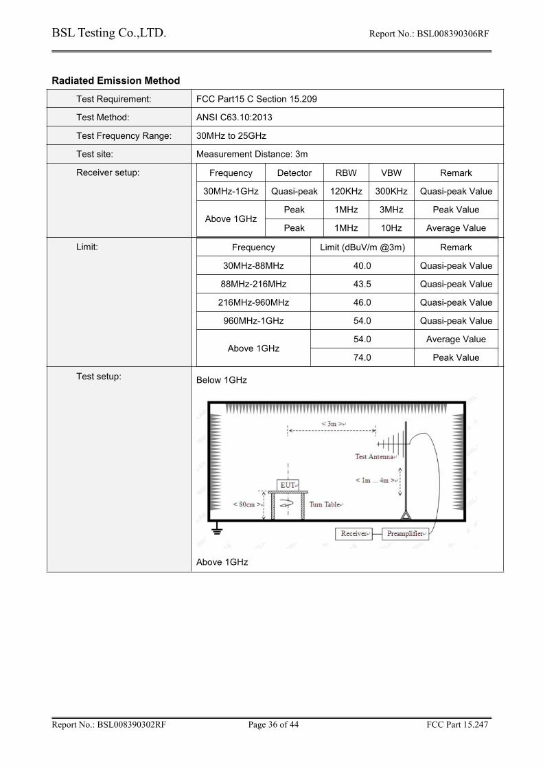
Radiated Emission Method
Test Requirement: FCC Part15 C Section 15.209
Test Method: ANSI C63.10:2013
Test Frequency Range: 30MHz to 25GHz
Test site: Measurement Distance: 3m
Receiver setup: Frequency Detector RBW VBW Remark
30MHz-1GHz Quasi-peak 120KHz 300KHz Quasi-peak Value
Above 1GHzPeak 1MHz 3MHz Peak Value
Peak 1MHz 10Hz Average Value
Limit: Frequency Limit (dBuV/m @3m) Remark
30MHz-88MHz 40.0 Quasi-peak Value
88MHz-216MHz 43.5 Quasi-peak Value
216MHz-960MHz 46.0 Quasi-peak Value
960MHz-1GHz 54.0 Quasi-peak Value
Above 1GHz54.0 Average Value
74.0 Peak Value
Test setup: Below 1GHz
Above 1GHz
BSL Testing Co.,LTD. Report No.: BSL008390306RF
Report No.: BSL008390302RF Page 37 of 44 FCC Part 15.247
Test Procedure: 1. The EUT was placed on the top of a rotating table (0.8 meters below 1Gand 1.5 meters above 1G) above the ground at a 3 meter camber. Thetable was rotated 360 degrees to determine the position of the highestradiation.
2. The EUT was set 3 meters away from the interference-receivingantenna, which was mounted on the top of a variable-height antennatower.
3. The antenna height is varied from one meter to four meters above theground to determine the maximum value of the field strength. Bothhorizontal and vertical polarizations of the antenna are set to make themeasurement.
4. For each suspected emission, the EUT was arranged to its worst caseand then the antenna was tuned to heights from 1 meter to 4 meters andthe rota table was turned from 0 degrees to 360 degrees to find themaximum reading.
5. The test-receiver system was set to Peak Detect Function and SpecifiedBandwidth with Maximum Hold Mode.
6. If the emission level of the EUT in peak mode was 10dB lower than thelimit specified, then testing could be stopped and the peak values of theEUT would be reported. Otherwise the emissions that did not have 10dBmargin would be re-tested one by one using peak, quasi-peak oraverage method as specified and then reported in a data sheet.
Test Instruments: Refer to section 1.7 for details
Test mode: Refer to section 1.2 for details
Test results: Pass
Remark:
1. During the test, pre-scan the GFSK, Pi/4QPSK, 8DPSK modulation, and found the GFSK modulationwhich it is worse case.
2. Pre-scan all kind of the place mode (X-axis, Y-axis, Z-axis), and found the Y-axis which it is worse case.
BSL Testing Co.,LTD. Report No.: BSL008390306RF
Report No.: BSL008390302RF Page 38 of 44 FCC Part 15.247
Measurement data:
Vertical:
BSL Testing Co.,LTD. Report No.: BSL008390306RF
Report No.: BSL008390302RF Page 39 of 44 FCC Part 15.247
Horizontal:
BSL Testing Co.,LTD. Report No.: BSL008390306RF
Report No.: BSL008390302RF Page 40 of 44 FCC Part 15.247
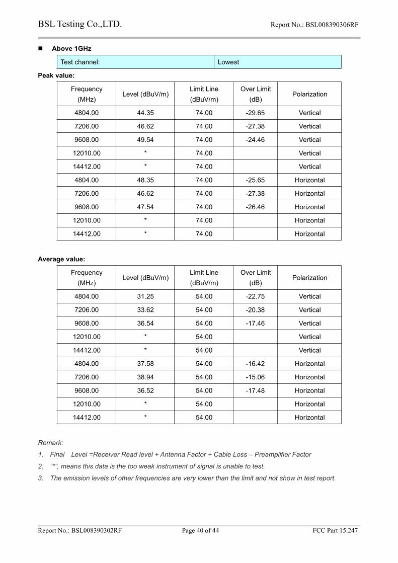
Above 1GHz
Test channel: Lowest
Peak value:
Frequency(MHz)
Level (dBuV/m)Limit Line(dBuV/m)
Over Limit(dB)
Polarization
4804.00 44.35 74.00 -29.65 Vertical
7206.00 46.62 74.00 -27.38 Vertical
9608.00 49.54 74.00 -24.46 Vertical
12010.00 * 74.00 Vertical
14412.00 * 74.00 Vertical
4804.00 48.35 74.00 -25.65 Horizontal
7206.00 46.62 74.00 -27.38 Horizontal
9608.00 47.54 74.00 -26.46 Horizontal
12010.00 * 74.00 Horizontal
14412.00 * 74.00 Horizontal
Average value:
Frequency(MHz)
Level (dBuV/m)Limit Line(dBuV/m)
Over Limit(dB)
Polarization
4804.00 31.25 54.00 -22.75 Vertical
7206.00 33.62 54.00 -20.38 Vertical
9608.00 36.54 54.00 -17.46 Vertical
12010.00 * 54.00 Vertical
14412.00 * 54.00 Vertical
4804.00 37.58 54.00 -16.42 Horizontal
7206.00 38.94 54.00 -15.06 Horizontal
9608.00 36.52 54.00 -17.48 Horizontal
12010.00 * 54.00 Horizontal
14412.00 * 54.00 Horizontal
Remark:
1. Final Level =Receiver Read level + Antenna Factor + Cable Loss – Preamplifier Factor
2. “*”, means this data is the too weak instrument of signal is unable to test.
3. The emission levels of other frequencies are very lower than the limit and not show in test report.
BSL Testing Co.,LTD. Report No.: BSL008390306RF
Report No.: BSL008390302RF Page 41 of 44 FCC Part 15.247
Test channel: Middle
Peak value:
Frequency(MHz)
Level (dBuV/m)Limit Line(dBuV/m)
Over Limit(dB)
Polarization
4882.00 45.58 74.00 -28.42 Vertical
7323.00 47.65 74.00 -26.35 Vertical
9764.00 48.94 74.00 -25.06 Vertical
12205.00 74.00 Vertical
14646.00 74.00 Vertical
4882.00 47.58 74.00 -26.42 Horizontal
7323.00 48.95 74.00 -25.05 Horizontal
9764.00 46.62 74.00 -27.38 Horizontal
12205.00 74.00 Horizontal
14646.00 74.00 Horizontal
Average value:
Frequency(MHz)
Level (dBuV/m)Limit Line(dBuV/m)
Over Limit(dB)
Polarization
4882.00 33.52 54.00 -20.48 Vertical
7323.00 34.54 54.00 -19.46 Vertical
9764.00 36.84 54.00 -17.16 Vertical
12205.00 54.00 Vertical
14646.00 54.00 Vertical
4882.00 38.95 54.00 -15.05 Horizontal
7323.00 36.63 54.00 -17.37 Horizontal
9764.00 37.25 54.00 -16.75 Horizontal
12205.00 54.00 Horizontal
14646.00 54.00 Horizontal
Remark:
1. Final Level =Receiver Read level + Antenna Factor + Cable Loss – Preamplifier Factor
2. “*”, means this data is the too weak instrument of signal is unable to test.
3. The emission levels of other frequencies are very lower than the limit and not show in test report.
BSL Testing Co.,LTD. Report No.: BSL008390306RF
Report No.: BSL008390302RF Page 42 of 44 FCC Part 15.247
Test channel: Highest
Peak value:
Frequency(MHz)
Level (dBuV/m)Limit Line(dBuV/m)
Over Limit(dB)
Polarization
4960.00 44.58 74.00 -29.42 Vertical
7440.00 45.24 74.00 -28.76 Vertical
9920.00 48.51 74.00 -25.49 Vertical
12400.00 74.00 Vertical
14880.00 74.00 Vertical
4960.00 49.52 74.00 -24.48 Horizontal
7440.00 45.55 74.00 -28.45 Horizontal
9920.00 47.48 74.00 -26.52 Horizontal
12400.00 74.00 Horizontal
14880.00 74.00 Horizontal
Average value:
Frequency(MHz)
Level (dBuV/m)Limit Line(dBuV/m)
Over Limit(dB)
Polarization
4960.00 34.58 54.00 -19.42 Vertical
7440.00 36.65 54.00 -17.35 Vertical
9920.00 38.25 54.00 -15.75 Vertical
12400.00 54.00 Vertical
14880.00 54.00 Vertical
4960.00 38.47 54.00 -15.53 Horizontal
7440.00 35.84 54.00 -18.16 Horizontal
9920.00 36.95 54.00 -17.05 Horizontal
12400.00 54.00 Horizontal
14880.00 54.00 Horizontal
BSL Testing Co.,LTD. Report No.: BSL008390306RF
Report No.: BSL008390302RF Page 43 of 44 FCC Part 15.247
15. Test Setup Photo
Radiated Emission
BSL Testing Co.,LTD. Report No.: BSL008390306RF
Report No.: BSL008390302RF Page 44 of 44 FCC Part 15.247