ETSI EN 300 417-7-1 V1.1.1 (2000-10) European Standard (Telecommunications series) Transmission and Multiplexing (TM); Generic requirements of transport functionality of equipment; Part 7-1: Equipment management and auxiliary layer functions
Transcript
ETSI EN 300 417-7-1 V1.1.1 (2000-10)European Standard (Telecommunications series)
Transmission and Multiplexing (TM);Generic requirements of
transport functionality of equipment;Part 7-1: Equipment management
and auxiliary layer functions
ETSI
ETSI EN 300 417-7-1 V1.1.1 (2000-10)2
ReferenceDEN/TM-01015-7-1
Keywordsgeneric, SDH, PDH, transmission
ETSI
650 Route des LuciolesF-06921 Sophia Antipolis Cedex - FRANCE
Tel.: +33 4 92 94 42 00 Fax: +33 4 93 65 47 16
Siret N° 348 623 562 00017 - NAF 742 CAssociation à but non lucratif enregistrée à laSous-Préfecture de Grasse (06) N° 7803/88
Important notice
Individual copies of the present document can be downloaded from:http://www.etsi.org
The present document may be made available in more than one electronic version or in print. In any case of existing orperceived difference in contents between such versions, the reference version is the Portable Document Format (PDF).
In case of dispute, the reference shall be the printing on ETSI printers of the PDF version kept on a specific network drivewithin ETSI Secretariat.
Users of the present document should be aware that the document may be subject to revision or change of status.Information on the current status of this and other ETSI documents is available at http://www.etsi.org/tb/status/
If you find errors in the present document, send your comment to:[email protected]
Copyright Notification
No part may be reproduced except as authorized by written permission.The copyright and the foregoing restriction extend to reproduction in all media.
Intellectual Property Rights ................................................................................................................................6
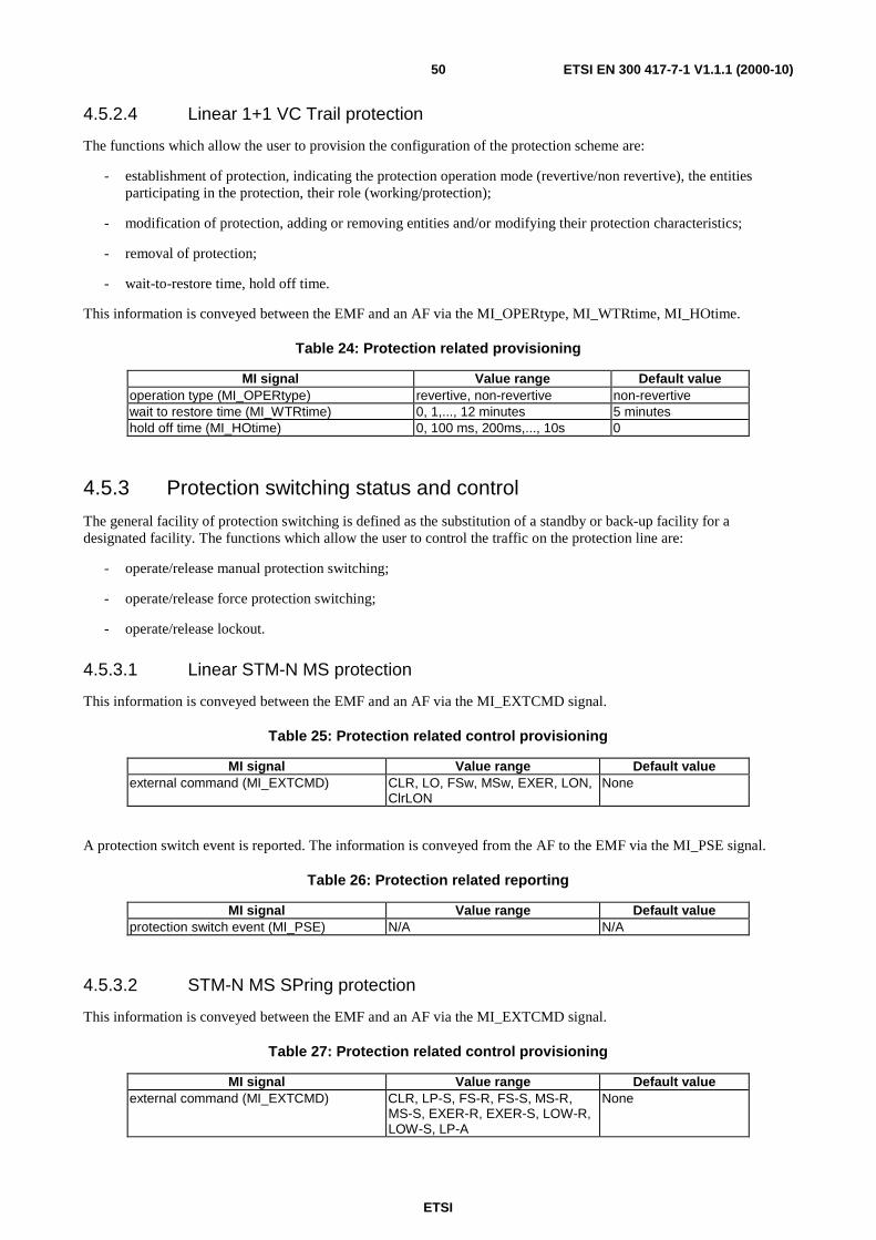
along the trail ........................................................................................................................................464.4.5.7 Pointer Justification Event package ......................................................................................................474.5 Configuration Management Functions .............................................................................................................474.5.1 Network element configuration ..................................................................................................................484.5.2 Protection switching provisioning ..............................................................................................................484.5.2.1 Linear STM-N MS protection ...............................................................................................................494.5.2.2 STM-N MS SPring protection...............................................................................................................494.5.2.3 Linear 1+1 SNC protection ...................................................................................................................49
ETSI
ETSI EN 300 417-7-1 V1.1.1 (2000-10)4
4.5.2.4 Linear 1+1 VC Trail protection.............................................................................................................504.5.3 Protection switching status and control ......................................................................................................504.5.3.1 Linear STM-N MS protection ...............................................................................................................504.5.3.2 STM-N MS SPring protection...............................................................................................................504.5.3.3 Linear 1+1 SNC protection ...................................................................................................................514.5.3.4 Linear 1+1 VC Trail protection.............................................................................................................514.5.4 Trace identifier processes provisioning and reporting ................................................................................514.5.5 Payload structures provisioning and reporting............................................................................................524.5.6 Multiplex structures provisioning and reporting.........................................................................................524.5.6.1 AUG provisioning.................................................................................................................................524.5.6.2 AUG autonomous adaptation ................................................................................................................534.5.6.3 AUG reporting ......................................................................................................................................534.5.6.4 TUG provisioning .................................................................................................................................534.5.6.5 TUG reporting.......................................................................................................................................534.5.7 Matrix connections provisioning ................................................................................................................544.5.8 DEG thresholds setting ...............................................................................................................................564.5.9 Port mode, Termination Point mode provisioning......................................................................................564.5.10 Access Point mode provisioning.................................................................................................................564.5.11 Defect reporting provisioning .....................................................................................................................564.5.12 2 Mbit/s multiframe alignment provisioning ..............................................................................................574.5.13 Network element synchronization provisioning .........................................................................................574.5.13.1 Quality Level mode provisioning..........................................................................................................574.5.13.2 Timing Marker mode provisioning .......................................................................................................574.5.13.3 SSM and TM support provisioning.......................................................................................................574.5.13.4 SSM and TM disabling provisioning ....................................................................................................584.5.13.5 Qloverwrite and QlfixedValue provisioning .........................................................................................584.5.13.6 CSid assignment....................................................................................................................................584.5.13.7 QLminimum provisioning.....................................................................................................................584.5.13.8 NE clock behaviour...............................................................................................................................584.5.13.9 NS Priority configuration......................................................................................................................594.5.13.10 NS Lockout commands .........................................................................................................................594.5.13.11 NS External commands.........................................................................................................................594.5.13.12 NS Wait to restore time.........................................................................................................................594.5.13.13 Select Sa bit for SSM provisioning .......................................................................................................604.5.14 Performance Monitoring 15 minute and 24 hour TR and RTR threshold setting .......................................60
5 DCC Layer Functions.............................................................................................................................615.1 DCC connection function DCC_C ...................................................................................................................62
Annex A (informative): Applications/Topologies of Performance Monitoring ................................67
A.1 Single-ended, bi-directional performance monitoring architecture at a termination node.....................67
A.2 Single-ended, bi-directional performance monitoring architecture at an intermediate node .................68
A.3 Dual ended, bi-directional performance monitoring architecture at termination nodes.........................69
A.4 Performance monitoring architecture at an intermediate node for fault localization .............................69
A.5 Single ended, bi-directional TCM related performance monitoring architecture at a TCtermination node.....................................................................................................................................70
A.6 Single ended, bi-directional TCM related performance monitoring architecture at an intermediatenode ........................................................................................................................................................71
Annex B (informative): Examples of some performance monitoring packages ...............................72
Annex C (informative): Use of NPME/FPME functions when both G.826 and M.2100/M.2101packages are selected for one termination point.........................................74
History ..............................................................................................................................................................78
ETSI
ETSI EN 300 417-7-1 V1.1.1 (2000-10)6
Intellectual Property RightsIPRs essential or potentially essential to the present document may have been declared to ETSI. The informationpertaining to these essential IPRs, if any, is publicly available for ETSI members and non-members, and can be foundin ETSI SR 000 314: "Intellectual Property Rights (IPRs); Essential, or potentially Essential, IPRs notified to ETSI inrespect of ETSI standards", which is available from the ETSI Secretariat. Latest updates are available on the ETSI Webserver (http://www.etsi.org/ipr).
Pursuant to the ETSI IPR Policy, no investigation, including IPR searches, has been carried out by ETSI. No guaranteecan be given as to the existence of other IPRs not referenced in ETSI SR 000 314 (or the updates on the ETSI Webserver) which are, or may be, or may become, essential to the present document.
ForewordThis European Standard (Telecommunications series) has been produced by ETSI Technical Committee Transmissionand Multiplexing (TM).
The present document is one of a family of documents that has been produced in order to provide inter-vendor andinter-operator compatibility of Synchronous Digital Hierarchy (SDH) equipment.
The present document is Part 7-1 of a multi-part EN covering the generic requirements of transport functionality ofequipment, as identified below:
Part 1-1: "Generic processes and performance";
Part 1-2: "General information about Implementation Conformance Statement (ICS) proforma";
Part 2-1: "Synchronous Digital Hierarchy (SDH) and Plesiochronous Digital Hierarchy (PDH) physical sectionlayer functions";
Part 2-2: "Synchronous Digital Hierarchy (SDH) and Plesiochronous Digital Hierarchy (PDH) physical sectionlayer functions; Implementation Conformance Statement (ICS) proforma specification";
Part 3-1: "Synchronous Transport Module-N (STM-N) regenerator and multiplex section layer functions";
Part 3-2: "Synchronous Transport Module-N (STM-N) regenerator and multiplex section layer functions;Implementation Conformance Statement (ICS) proforma specification";
Part 4-1: "Synchronous Digital Hierarchy (SDH) path layer functions";
Part 4-2: "Synchronous Digital Hierarchy (SDH) path layer functions; Implementation Conformance Statement(ICS) proforma specification";
Part 5-1: "Plesiochronous Digital Hierarchy (PDH) path layer functions";
Part 5-2: "Plesiochronous Digital Hierarchy (PDH) path layer functions; Implementation Conformance Statement(ICS) proforma specification";
Various of the above parts have previously been published as parts of ETS 300 417.
They have been converted into parts of EN 300 417 without technical changes, but some editorial changes have beennecessary (e.g. references). In particular:
- Parts 2-1, 2-2 and 3-2 have been modified to take account of editorial errors present in edition 1;
- Part 1-1 has had its title change to align with other parts published at a later date.
Also note that in the meantime Parts 8-1 and 8-2 together with all Parts x-3 (Abstract Test Suites) have been stopped.
National transposition dates
Date of adoption of this EN: 13 October 2000
Date of latest announcement of this EN (doa): 31 January 2001
Date of latest publication of new National Standardor endorsement of this EN (dop/e): 31 July 2001
Date of withdrawal of any conflicting National Standard (dow): 31 July 2001
IntroductionThe present document specifies for fault management, performance monitoring, and configuration management alibrary of basic equipment management function (EMF) building blocks and a set of rules by which they are combinedin order to describe an equipment's EMF functionality. The library defined in the present document forms part of the setof libraries defined furthermore in the other parts of EN 300 417. In addition, a number of compound functionsconsisting of a number of EMF building blocks are defined.
NOTE: Not every function defined in the present document is required for every application. Different subsets offunctions may be assembled in different ways to provide a variety of different capabilities. Networkoperators and equipment suppliers may choose which functions to implement for each application.
In addition, the present document specifies functions in the auxiliary layers: DCC layer and V11 section layer.
ETSI
ETSI EN 300 417-7-1 V1.1.1 (2000-10)8
1 ScopeThe present document specifies a library of basic building blocks and a set of rules by which they are combined in orderto describe transport and equipment management function (EMF) functionality in equipment. The library comprises thefunctional building blocks needed to completely specify the generic functional structure of the European DigitalTransmission Hierarchy. Equipment, which is compliant with the present document, will be describable as aninterconnection of a subset of these functional blocks contained within the present document. The interconnections ofthese blocks will obey the combination rules given. The generic functionality is described in EN 300 417-1-1 [8].
2 ReferencesThe following documents contain provisions which, through reference in this text, constitute provisions of the presentdocument.
• References are either specific (identified by date of publication, edition number, version number, etc.) ornon-specific.
• For a specific reference, subsequent revisions do not apply.
• For a non-specific reference, the latest version applies.
• A non-specific reference to an ETS shall also be taken to refer to later versions published as an EN with the samenumber.
[1] ETSI ETS 300 147 (1997): "Transmission and Multiplexing (TM); Synchronous Digital Hierarchy(SDH); Multiplexing structure".
[2] ETSI ETS 300 167: "Transmission and Multiplexing (TM); Functional characteristics of2 048 kbit/s interfaces".
[3] ETSI ETS 300 304: "Transmission and Multiplexing (TM); Synchronous Digital Hierarchy(SDH); SDH information model for the Network Element (NE) view".
[4] ETSI EN 300 371: "Transmission and Multiplexing (TM); Plesiochronous Digital Hierarchy(PDH) information model for the Network Element (NE) view".
[5] ETSI ETS 300 411: "Transmission and Multiplexing (TM); Performance monitoring; Informationmodel for the Network Element (NE) view".
[6] ETSI ETS 300 412: "Transmission and Multiplexing (TM); Payload Configuration; Informationmodel for the Network Element (NE) view".
[7] ETSI ETS 300 413: "Transmission and Multiplexing (TM); Multiplex section protection;Information model for the Network Element (NE) view".
[8] ETSI EN 300 417-1-1: "Transmission and Multiplexing (TM); Generic requirements of transportfunctionality of equipment; Part 1-1: Generic processes and performance".
[9] ETSI EN 300 417-4-1: "Transmission and Multiplexing (TM); Generic requirements of transportfunctionality of equipment; Part 4-1: Synchronous Digital Hierarchy (SDH) path layer functions".
[10] ETSI EN 300 417-6-1: "Transmission and Multiplexing (TM); Generic requirements of transportfunctionality of equipment; Part 6-1: Synchronization layer functions".
[11] ETSI ETS 300 493: "Transmission and Multiplexing (TM); Synchronous Digital Hierarchy (SDH)information model of the Sub Network Connection Protection (SNCP) for the Network Element(NE) view".
[12] ETSI EN 301 167: "Transmission and Multiplexing (TM); Management of Synchronous DigitalHierarchy (SDH) transmission equipment; Fault management and performance monitoring;Functional description".
ETSI
ETSI EN 300 417-7-1 V1.1.1 (2000-10)9
[13] ETSI EN 301 155: "Synchronous Digital Hierarchy (SDH); Unidirectional performancemonitoring for the network element view".
[14] ETSI EN 301 268: "Telecommunications Management Network (TMN); Linear multiplex sectionprotection configuration information model for the Network Element (NE) view".
[15] ETSI ETS 300 337: "Transmission and Multiplexing (TM); Generic frame structures for thetransport of various signals (including Asynchronous Transfer Mode (ATM) cells andSynchronous Digital Hierarchy (SDH) elements) at the ITU-T Recommendation G.702hierarchical rates of 2 048 kbit/s, 34 368 kbit/s and 139 264 kbit/s".
[16] ETSI EN 301 384: "Telecommunications Management Network (TMN); Performance monitoringfor Plesynchronous Digital Hierarchy (PDH) interfaces; Information model for the NetworkElement (NE) view".
[17] ETSI ES 202 098: "Telecommunications Management Network (TMN); Information model for aVC transport system using a 34 Mbit/s PDH transmission system in accordance with ITU-TRecommendation G.832".
[18] ITU-T Recommendation G.774 (1992): "Synchronous digital hierarchy (SDH) managementinformation model for the network element view".
[19] ITU-T Recommendation G.826 (02/99): "Error performance parameters and objectives forinternational, constant bit rate digital paths at or above the primary rate".
[20] ITU-T Recommendation G.828 (02/00): "Error performance parameters and objectives forinternational, constant bit rate synchronous digital paths".
[21] ITU-T Recommendation M.20 (1992): "Maintenance philosophy for telecommunicationsnetworks".
[22] ITU-T Recommendation M.2100 (1995): "Performance limits for bringing-into-service andmaintenance of international PDH paths, sections and transmission systems".
[23] ITU-T Recommendation M.2101 (1997): "Performance limits for bringing-into-service andmaintenance of international SDH paths and multiplex sections".
[24] ITU-T Recommendation M.2101.1 (1997): "Performance limits for bringing-into-service andmaintenance of international SDH paths and multiplex sections".
[25] ITU-T Recommendation M.2120 (1997): "PDH path, section and transmission system and SDHpath and multiplex section fault detection and localization procedures".
[26] ITU-T Recommendation Q.822 (1994): "Stage 1, Stage 2 and Stage 3 description for theQ3 interface – Performance management".
[27] ITU-T Recommendation Q.921 (1997): "ISDN user-network interface – Data link layerspecification".
[28] ITU-T Recommendation V.11 (1996): "Electrical characteristics for balanced double-currentinterchange circuits operating at data signalling rates up to 10 Mbit/s".
ETSI
ETSI EN 300 417-7-1 V1.1.1 (2000-10)10
3 Definitions, abbreviations, symbols and diagrammaticconventions
3.1 DefinitionsFor the purposes of the present document, the terms and definitions given in EN 300 417-1-1 [8] apply.
3.2 AbbreviationsFor the purposes of the present document, the following abbreviations apply:
15m 15 minutes24h 24 hoursAccPer Accumulation PeriodAcSL Accepted Signal LabelAcTI Accepted Trace IdentifierAF Atomic FunctionAvFb Availability Function bi-directionalAvFu Availability Function uni-directionalAI Adapted InformationAIS Alarm Indication SignalAP Access PointAPI Access Point IdentifierARCH ARCHitectureATM Asynchronous Transfer ModeAU Administrative UnitAUG Administrative Unit GroupA/Z from A to ZBBE Background Block ErrorBUT Begin of Unavailable TimeCI Characteristic InformationCK ClocKCLR CLeaRClrLON Clear Lockout of Normal traffic signal from protectionCM Configuration ManagementCM Connection MatrixCP Connection PointCRC Cyclic Redundancy CheckCS Clock SourceCSES Consecutive Severely Errored SecondsCur15m Current 15 minutesCur24h Current 24 hourDCC Data Communications ChannelDEC DECrementDEG DEGradedDEGM DEGraded Monitor periodDEGTHR DEGraded THresholdDMA Deferred Maintenance AlarmDS Defect SecondEBC Errored Block CountEDC Error Detection CodeEFS Equipment Functional SpecificationEMF Equipment Management FunctionEQ EQuipmentES Electrical SectionES Errored SecondEUT End of Unavailable TimeEXER Exercise
ETSI
ETSI EN 300 417-7-1 V1.1.1 (2000-10)11
EXER-R Exercise - RingEXER-S Exercise - SpanEXTCMD EXTernal CoMmanDExTI Expected Trace IdentifierF_B Far-end BlockFAS Frame Alignment SignalFBBE Far-end Background Block ErrorFES Far-end Errored SecondFFS For Further StudyFPME Far-end Performance Monitoring EventFOP Failure Of ProtocolFS Frame Start signalFSES Far-end Severely Errored SecondFS-R Forced Switch to protection - ringFS-S Forced Switch to protection - spanFSw Forced SwitchG826EN G.826 [19] bi-directional package at the trail end nodeG826IN G.826 [19] bi-directional package at intermediate nodeHO Hold Off (used in HOTime)ID IDentifierIM In Multiframe stateINC INCrementIncAIS Incoming AISLO Lockout Of protectionLOF Loss Of FrameLOM Loss Of MultiframeLON Lockout Of Normal traffic signal from protectionLOP Loss Of PointerLOS Loss Of SignalLOW-R Lockout Of Working channels - ring switchLOW-S Lockout Of Working channels - span switchLP-A Lockout of Protection – All spansLP-S Lockout of Protection - SpanLSS Loss of Sequence StructureLTC Loss of Tandem ConnectionMC Matrix ConnectionMCF Message Communications FunctionMEI Maintenance Event InformationMFP MultiFrame PresentMI Management InformationMP Management PointMO Managed ObjectMON MONitoredMP Management PointMS Multiplex SectionMS1 STM-1 Multiplex SectionMS16 STM-16 Multiplex SectionMS4 STM-4 Multiplex SectionMS64 STM-64 Multiplex SectionMSP Multiplex Section ProtectionMS-R Manual Switch to protection - ringMS-S Manual Switch to protection - spanMSw Manual SwitchN/A Not ApplicableNBBE Near-end Background Block ErrorNC Network ConnectionNE Network ElementNES Near-end Errored SecondNMON Not MONitoredNPME Near-end Performance Monitoring EventNSES Near-end Severely Errored SecondODI Outgoing Defect Indication
ETSI
ETSI EN 300 417-7-1 V1.1.1 (2000-10)12
OEI Outgoing Error IndicationOF Outgoing Far-endOH OverHeadON Outgoing Near-endOPER OPERationOS Optical SectionOW Order WireP ProtectionP12s 2 048 kbit/s PDH path layer with synchronous 125 µs frame structure according to
ETS 300 167 [2]P22e 8 448 kbit/s PDH path layer with 4 plesiochronous 2 048 kbit/sP31e 34 368 kbit/s PDH path layer with 4 plesiochronous 8 448 kbit/sP31s 34 368 kbit/s PDH path layer with synchronous 125 µs frame structure according to
ETS 300 337 [15]P4e 139 264 kbit/s PDH path layer with 4 plesiochronous 34 368 kbit/sP4s 139 264 kbit/s PDH path layer with synchronous 125 µs frame structure according to
TIM Trace Identifier MismatchTIMdis Trace Identifier Mismatch disableTMN Telecommunications Management NetworkTP Timing PointTPmode Termination Point modeTR Threshold ReportTS Time SlotTSE Test Sequence ErrorTSN Tibutary Signal NumberTT Trail Termination functionTTI Trail Trace IdentifierTU Tributary UnitTUG Tributary Unit GroupTxTI Transmitted Trace IdentifierUAS Unavailable SecondUAT Unavailable TimeUNEQ UNEQuippedUTC Universal Time CoordinatedVC Virtual ContainerVC-n Virtual Container, level nW WorkingWTR Wait To RestoreZ/A from Z to A
3.3 Symbols and diagrammatic conventionsFor the purposes of the present document, the symbols and diagrammatic conventions described in EN 300 417-1-1 [8]apply.
4 Equipment management functionThe equipment management function (EMF) (figure 1) provides the means through which a network element levelmanager manages the network element function (NEF).
The EMF interacts with the transport and synchronization layer atomic functions by exchanging information(MI: management information) across the MP reference points. The EMF contains a number of functions that provide adata reduction mechanism on the information received across the MP reference points. These function outputs areavailable to the agent via the network element resources and management application functions (MAF) which representthis information as managed objects.
Network element resources provide event processing and storage. The MAF process the information provided to and bythe NE resources. For example, the agent converts this information to CMISE (common management informationservice element) messages and responds to CMISE messages from the manager by performing the appropriateoperations on the managed objects.
NOTE: The management application function specification is outside the scope of the present document.
Network elements may support several functions, which can be operated only in exclusivity of each other. Besides suchconfiguration provisionings, provisionings are needed for parameters in individual functions and processes within a NE.
A number of functions/processes and reports have a notion of time. The network element Real Time Clock functionprovides this time information.
ETSI
ETSI EN 300 417-7-1 V1.1.1 (2000-10)14
NE-RTC
FaultManagement
PerformanceMonitoring
ConfigurationManagement
ManagmentApplicationFunctions
MI_cXXX
MI_pXXX
MI_XXX
MI_1second
SD_CI_CK
MP
Figure 1: Equipment Management Function process block diagram
MP
The MI at this point is a set of management signals to/from the atomic functions, including configuration and operationcontrol, fault management, performance monitoring, protection switching, synchronization control and reportingsignals.
SD_CP
The CI at this point is the SD_CI_CK signal.
4.1 Network Element - Real Time Clock (NE-RTC) FunctionSymbol:
NE-RTCRealTimeclock
SET-RTC
SD_TI_CK
Figure 2: NE RTC function
ETSI
ETSI EN 300 417-7-1 V1.1.1 (2000-10)15
Interfaces:
Table 1: NE-RTC input and output signals
Input(s) Output(s)SET-RTCSD_TI_CK
NE-RTC
Processes:
The real time clock is a logical entity within the NE which provides date and time information to equipmentmanagement functions within the NE.
The real time clock shall have a resolution of 1 second.
The date shall be represented as year:month:day and be "year 2000" compliant. The time shall be represented ashour:minute:second.
On receipt of the SET-RTC command, the real time clock shall be set to the date:time specified by the SET-RTCcommand.
On a regular basis, the RTC is to be realigned with UTC. This realignment period should be determined such that thecorrection is less than ±10 seconds to prevent that all active PMFs declare suspect intervals.
The real time clock may be a free running clock or may be locked to any available clock source (e.g. equipment clockSD_TI_CK).
The stability of the real time clock shall be such that in any 24 hour period (where a SET-RTC command has not beenreceived), the RTC shall not have deviated by more than ±Y seconds from the 24 hour period of a UTC; Y is for furtherstudy.
When a SET-RTC command is received, the error between the Management command at the input to the NE (figure 3)and the resultant NE-RTC time shall be within ± X seconds; X is for further study.
NOTE: The relationship and timing transfer between the management command at the input to the NE and theresultant SET-RTC command is beyond the scope of the present document.
NE
NE Processingand all internaldelays
SET_RTC
RTCNE_RTC
Message UTC
+/- Xseconds
Figure 3: NE_RTC and UTC relation
ETSI
ETSI EN 300 417-7-1 V1.1.1 (2000-10)16
4.2 Fault Management FunctionsThe equipment management function within the network element performs a persistency check on the fault causesbefore it declares a fault cause a failure. The fault causes are generated by the atomic function fault managementprocess. A severity is associated with each alarm.
The failure is reported via the agent process (output failure report) and by means of alarms (audible and visibleindicators). Typically, alarms can be divided into unit level alarms, NE level alarms and station alarms.
UnitAlarms
Network ElementAlarms
StationAlarms
Failure Reportsto TMN
fault CausecZZZ
FailurefZZZ
severityassignment
ManagementApplicationFunction
f4 f5
f6
f7
f8
Figure 4: Fault management inside EMF function
Filter Functionf4 integration of fault causes into failuresf5 assign severity to failuref6 translation of failures into Unit alarmsf7 translation of failures into Network Element alarms (e.g. severity)f8 translation of failures into station alarms & alarm disconnect control
4.2.1 Failure filter f4
A transmission failure shall be declared if the fault cause persists continuously for 2,5 ± 0,5 seconds. The failure shallbe cleared if the fault cause is absent continuously for 10 ± 0,5 seconds.
The failure change (declaration/clearing) shall be time stamped. The time stamp shall indicate the start of the fault causeto failure integration time. The time stamp shall have an accuracy of 1 second relative to the NE-RTC.
A severity is used to indicate the management perception of the severity of a fault which could depend on the servicedependency of the fault. Refer to EN 301 167 [12].
NOTE: Two severity schemes are being used. One based on the ITU-T Recommendations X series which has theseverity elements: critical, major, minor and warning. The other based on theITU–T Recommendation M.20 [21] which has the severity elements: prompt maintenance alarm (PMA),deferred maintenance alarm (DMA) and maintenance event information (MEI).
4.2.3 Replaceable unit alarm filter f6
There are so many preferences amongst the public network operators, standardization of the unit alarms is not possibleat the moment.
NOTE: The role of this interface within management procedures should be reviewed in light of increasedfunctionality of the Q interface.
4.2.4 Network element alarm filter f7
There are so many preferences amongst the public network operators, standardization of the network element alarms isnot possible at the moment.
NOTE: The role of this interface within management procedures should be reviewed in light of increasedfunctionality of the Q interface.
4.2.5 Station alarm filter f8
There are so many preferences amongst the public network operators, standardization of the network element alarms isnot possible at the moment.
NOTE: The role of this interface within management procedures should be reviewed in light of increasedfunctionality of the Q interface.
4.3 Management Application FunctionsRefer to information model standards (ETS 300 304 [3], EN 300 371 [4], ETS 300 411 [5], ETS 300 412 [6], ETS 300413 [7], ETS 300 493 [11], EN 301 155 [13], EN 301 268 [14], EN 301 384 [16], ES 202 098 [17]).
4.4 Performance Monitoring FunctionsThe EMF performance monitoring process collects the event counts associated with:
- the trail performance parameters Errored Seconds (ES), Severely Errored Seconds (SES), Background BlockError (BBE) and Unavailable Time (UAT)/Unavailable Second (UAS);
- the link connection performance parameter Pointer Justification Event (PJE).
It processes the event counts to derive the performance parameters, and stores these performance events in registers.Such information can be used to sectionalize faults and to locate sources of intermittent errors, and/or determine thequality of the service.
ETSI
ETSI EN 300 417-7-1 V1.1.1 (2000-10)18
Figure 5 presents an overview of the Performance Monitoring Functions (PMF) within the EMF. The shaded boxes arePMFs defined in the present document. The intermediate ellipses represent the interconnect options between the PMFs.The Equipment Functional Specification (EFS) defines which (sub)set of PMFs is (to be) supported by the equipment,as well as the quantity of each PMF.
NOTE 1: For the case where the number of transport atomic functions exceed the number of performancemonitoring resources, selection may be indicated by "performance monitoring connection functions", orby alternative means. This is outside the scope of the present document. For the case where a suchselectivity is not present or is not required, the interconnect is predefined and can be represented in theEFS by explicit interconnections between PMFs and atomic functions.
The NPME function determines on a per second basis the number of near-end background block errors (BBE), andwhether an ES and/or SES occurred. The FPME function determines on a per second basis the number of far-endBackground Block Errors (BBE), and whether an ES and/or SES occurred.
The AvFu function determines whether a one second is uni-directionally available or unavailable, and passes throughthe (ES, SES, BBE) input signal's value for seconds in available time. The input signal value in seconds in unavailabletime is not output, instead the value "0" is output. The AvFb function determines whether a one second is bi-directionally available or unavailable, and passes through the (ES, SES, BBE) input signal's value in seconds inavailable time. The input signal value in seconds in unavailable time is not output, instead the value "0" is output.
The delay function delays the input signal (which is not subject to "availability" processing) by 10 seconds to align itwith the performance monitoring time base which is 10 seconds delayed from the time of day.
The 15m function accumulates the input values (from i.e. ES, SES, BBE, PJE+, PJE-, TSE) over periods of 15 minutes.The function contains seventeen 15 minute registers: one current and 16 recent registers. The 24h function accumulatesthe input signal values over periods of 24 hours. The function contains two 24 hour registers: one current and one recentregister.
The ThrFs and ThrFd functions can be used to generate an autonomous event report (a threshold report) when the countin the current 15m/24h register to which it is connected reaches or exceeds the provisioned threshold value. In addition,the ThrFd function generates a reset threshold report when the count at the end of a 15m period has not crossed aprovisioned reset threshold.
The inputs to the performance monitoring process - the Performance Monitoring primitives (MI_pXXX) - are onesecond counts of:
- errored blocks (pX_EBC), defect second (pX_DS) generated by termination sink functions;
NOTE 3: Tandem connections support so called "Outgoing Defect Indication" and "Outgoing Error Indication".For details see ETS 300 147 [1] and EN 300 417-4-1 [9].
These primitives are passed from the Atomic Functions (AFs) to the Equipment Management Function (EMF) forfurther processing.
The Performance monitoring timing function outputs the 1 second indication (MI_1second) towards the atomicfunctions to perform the 1 second counting of the performance primitives pXXX.
ETSI
ETSI EN 300 417-7-1 V1.1.1 (2000-10)19
MI_pF_EBCMI_pF_DSMI_pN_DS
MI_pOF_EBCMI_pOF_DSMI_pON_DS
MI_pN_EBCMI_pN_DS
MI_pON_EBCMI_pON_DS
MI_pPJE+MI_pPJE-
NPME FPME
Cur15m UAT CSESCur24h
AvFu AvFb
ThrFs
PMC
MI_1second
Delay
Management Application Functions
MI_pN_TSE
ThrFd Rec15m Rec24h
PerformancePrimitives
PerformanceEvents
NESNSESNBBE
FESFSESFBBE
UAT
UAT
Figure 5: Overview of Performance Monitoring functions and their input/output relations
Performance monitoring functions connect to the higher layer management functions. Those functions are defined inETS 300 304 [3], ETS 300 411 [5], EN 301 155 [13], EN 301 167 [12] and other related standards. The presentdocument addresses performance monitoring from an equipment point of view. EN 301 167 [12] describes theperformance monitoring from a network point of view.
ETSI
ETSI EN 300 417-7-1 V1.1.1 (2000-10)20
4.4.1 Performance monitoring clock function PMC
Symbol:
NE-RTC
PMclock PMclock15m PMclock24h
10 secondsdelay
15 minuteintervalcounter
24 hourintervalcounter
1 secondperiods
MI_1second
Start24h
Figure 6: PM clock function
Interfaces:
Table 3: PM clock function input and output signals
Input(s) Output(s)NE-RTCStart24h
PMclockPMclock15mPMclock24hMI_1second
Processes:
The function generates the clock signals associated with the performance monitoring processing in the atomic functionsand the performance monitoring functions within a network element.
1 second periods: this function shall generate the 1second signal at the end of each 1 second period as indicated by theNE real time clock (NE-RTC).
10 seconds delay: for performance monitoring purposes, the NE-RTC shall be delayed by 10 seconds (PMclock) for thepurpose to accommodate the effects (a 10 second delay) associated with the unavailable time calculation.
15 minute interval counter: this process generates the 15 minute period indications (PMclock15m) which are alignedwith the end of each quarter of an hour period (00:00, 15:00, 30:00, 45:00) with respect to PMclock. The start of aperiod is equal to the end of the previous period. If the NE-RTC is not preset, each 15 minute period spans 900 onesecond periods.
24 hour interval counter: this process generates the 24 hour period indications (PMclock24h) which are aligned withthe end of a quarter of an hour period (00:00:00, 00:15:00, 00:30:00, … 23:45:00) with respect to PMclock. The start ofa period is equal to the end of the previous period. If the NE-RTC is not preset, each 24 hour period spans 86 400 onesecond periods.
For 24-hour data specifically, the NE may be instructed (Start24h) on when to begin measurement of the 24 hour periodfor the purpose of reporting data. The NE shall be able to begin the measurement at the start of any 15 minute period(refer to subclause 2.3.3.3 of ITU-T Recommendation M.2120 [25]) (default shall be 00:00 on the PMclock).
ETSI
ETSI EN 300 417-7-1 V1.1.1 (2000-10)21
4.4.2 Performance monitoring events functions
4.4.2.1 Near-end performance monitoring event function (NPME)
Symbol:
pN_DS
pN_EBC f14
f16
f13
NSES(t)
NES(t)
NBBE(t)
1second
NPMENSESestimator
P12s_CI_MFP(2 Mbit/s only)
Figure 7: Near-end performance monitoring event function symbol and process diagram
This function determines on a per second basis the number of near-end Background Block Errors (BBE), and whetheran ES and/or SES occurred.
The EBC and DS performance monitoring primitive signals received from a transport atomic function are the inputs forthe determination of the performance events BBE, ES, SES.
For the case a DS input is not connected, DS shall be assumed to be false. For the case a EBC input is not connected,EBC shall be assumed to be "0".
Figure 7 presents the processes and their interconnect within the Near-end Performance Monitoring Event (NPME)atomic performance monitoring function.
f13 (see note 1): a Near-end Errored Second (NES) performance monitoring event signal shall be generated if pN_DS isset or if pN_EBC ≥ 1; i.e.:
- NES ← (pN_DS = true) or (pN_EBC ≥ 1).
NOTE 1: "filter" numbers (e.g. "f13") are taken from EN 300 417-1-1 [8].
f14: a Near-end Severely Errored Second (NSES) performance monitoring event signal shall be generated if pN_DS isset or if pN_EBC ≥ NSESestimator (Near-end SESestimator); i.e.:
- NSES ← (pN_DS = true) or (pN_EBC ≥ NSESestimator).
NOTE 2: The NSESestimator value depends on the network layer this NPME function is connected to.
ETSI
ETSI EN 300 417-7-1 V1.1.1 (2000-10)22
For the case of 2 Mbit/s (P12s) signals, the following NSES definition shall apply:
- NSES ← (pN_DS = true) or [(pN_EBC ≥ NSESestimator) and CI_MFP = true)] or [(pN_EBC ≥ 28) and(CI_MFP = false)].
SES Estimator: the Near-end SES estimator value is network layer specific and shall be as specified in table 5.
Table 5: SES Estimators
Layer SES estimatorRS1 2 400 (refer to EN 301 167 [12] )RS4 FFSRS16RS64MS1 28 800 (refer to EN 301 167 [12] )MS4 FFSMS16MS64VC-4-64c 2 400 (refer to G.828 [20] )VC-4-16cVC-4-4cVC-4VC-3VC-2 600 (refer to G.828 [20] )VC-12VC-11P4s 2 400 (refer to annex B/G.826 [19] )P31sP4e 69 (refer to annex B/M.2100 [22] )P31e 52 (refer to annex B/M.2100 [22] )P22e 41 (refer to annex B/M.2100 [22] )P12s (FAS) (3) 28 (refer to annex B/M.2100 [22] )P12s (CRC) (1)(2) 805 or 300 (refer to annex B/M.2100 [22] and annex
B/G.826 [19] )NOTE 1: Two different values are being specified; for uni-directional performance
monitoring defined in ITU-T Recommendation M.2100 [22] the SESestimator is 805, while for bi-directional performance monitoring definedin G.826 [19] the SES estimator is 300. Refer to annex C.
NOTE 2: For a 2 Mbit/s path, P12s (CRC) values are applicable when the CRC-4interworking mode is either ON or AUTO with the latter case requiringCRC-4 multiframe alignment being detected. For the case of CRC-4interworking modes OFF and AUTO/loss of multiframe, PM has to bebased on FAS errors. Refer to annex C.
NOTE 3: SESestimator for the case FAS errors are used is 28; refer to ITU-TRecommendation M.2100 [22].
f16: the Near-end Background Block Error (NBBE) performance monitoring event signal shall equal pN_EBC if theNSES of that second is not set. Otherwise, NBBE shall be zero.
For the case of 2 Mbit/s (P12s) signals, the following NBBE definition shall apply:
the Near-end Background Block Error (NBBE) performance monitoring event signal shall equal pN_EBC if the NSESof that second is not set and CI_MFP is true. Otherwise, NBBE shall be zero.
NOTE 3: If the P12s has a CRC4mode of AUTO, the following should be observed: the BBE parameter is notdefined for P12s without CRC-4 and the classification of seconds as SES is done differently if there areCRC-4 or not. Consequently, if BBE measurements are done and CRC-4 is not persistently available, theresulting BBE count is unreliable. Also, the SES count is unreliable if the CRC-4 existence is not stablewith the pX_EBC being a mixture of FAS and EDC indications and a threshold value given by the MFP(CRC-4 existence) state at the end of the second. Therefore, care should be taken if PM measurements aredone on a P12s with CRC4mode being AUTO.
ETSI
ETSI EN 300 417-7-1 V1.1.1 (2000-10)23
4.4.2.2 Far-end performance monitoring event function (FPME)
Symbol:
f24
f26
f23
pF_DS
pF_EBC
FSES(t)
FES(t)
FBBE(t)
pN_DS
1secondFPME
FSESestimatorP12s_CI_MFP
Figure 8: Far-end performance monitoring event function symbol and process diagram
This function determines for on a per second basis the number of far-end Background Block Errors (BBE), and whetheran ES and/or SES occurred.
The EBC and DS performance monitoring primitive signals received from an atomic function are the inputs for thedetermination of the performance events BBE, ES, SES.
For the case a DS input is not connected, DS shall be assumed to be false. For the case a EBC input is not connected,EBC shall be assumed to be "0".
Figure 8 presents the processes and their interconnect within the Far-end Performance Monitoring Event (FPME)atomic performance monitoring function.
NOTE 1: Far-end represents either those signals that are called "far-end" or those signals that are called "outgoing"(tandem connection specific).
f23: a Far-end Errored Second (FES) performance monitoring event signal shall be generated if pF_DS is set or ifpF_EBC ≥ 1, and if that second is not a Near-end Defect Second (pN_DS); i.e.:
- FES ← (pN_DS = false) and ((pF_DS = true) or (pF_EBC ≥ 1)).
f24: a Far-end Severely Errored Second (FSES) performance monitoring event signal shall be generated if pF_DS is setor if pF_EBC ≥ FSESestimator (Far-end SES estimator), and that second is not a Near-end Defect Second; i.e.:
- FSES ← (pN_DS = false) and ((pF_DS = true) or (pF_EBC ≥ FSESestimator)).
NOTE 2: The FSESestimator value depends on the network layer this FPME function is connected to.
For the case of 2 Mbit/s (P12s) signals, the following FSES definition shall apply:
- FSES ← (pN_DS = false) and [(pF_DS = true) or ((pF_EBC ≥ FSESestimator) and (CI_MFP = true))].
ETSI
ETSI EN 300 417-7-1 V1.1.1 (2000-10)24
SES Estimator: the SES estimator value is network layer specific and shall be as specified in table 7.
Table 7: Far-end SES Estimators
Layer SES estimatorRS1 Not ApplicableRS4RS16RS64MS1 28 800 (refer to EN 301 167 [12] )MS4 FFSMS16MS64VC-4-64c 2 400 (refer to G.828 [20] )VC-4-16cVC-4-4cVC-4VC-3VC-2 600 (refer to G.828 [20] )VC-12VC-11P4s 2 400 (refer to annex B/G.826 [19] )P31sP4e Not Applicable (refer to annex B/M.2100 [22] )P31eP22eP12s (CRC) (note) 805 or 300 (refer to annex B/M.2100 [22] and annex B/G.826 [19]
)NOTE: Two different values are being specified; for uni-directional performance
monitoring defined in ITU-T Recommendation M.2100 [22] the SES estimatoris 805, while for bi-directional performance monitoring defined in G.826 [19]the SES estimator is 300. Refer to annex C.
f26: the Far-end Background Block Error (FBBE) performance monitoring event signal shall equal pF_EBC if theFSES of that second is not set and if that second is not a Near-end Defect Second. Otherwise, FBBE is zero.
For the case of 2 Mbit/s (P12s) signals, the following FBBE definition shall apply:
The Far-end Background Block Error (FBBE) performance monitoring event signal shall equal pF_EBC if the FSES ofthat second is not set and if that second is not a Near-end Defect Second and CI_MFP is true. Otherwise, FBBE shall bezero.
NOTE 3: If the P12s has a CRC4mode of AUTO, the following should be observed: the BBE parameter is notdefined for P12s without CRC-4 and the classification of seconds as SES is done differently if there areCRC-4 or not. Consequently, if BBE measurements are done and CRC-4 is not persistently available, theresulting BBE count is unreliable. Also, the SES count is unreliable if the CRC-4 existence is not stablewith the pX_EBC being a mixture of FAS and EDC indications and a threshold value given by the MFP(CRC-4 existence) state at the end of the second. Therefore, care should be taken if PM measurements aredone on a P12s with CRC4mode being AUTO.
ETSI
ETSI EN 300 417-7-1 V1.1.1 (2000-10)25
4.4.2.3 Uni-directional availability filter function (AvFu)
Symbol:
SES(t)
ES(t)
BBE(t)
ES(t-10)
SES(t-10)
BBE(t-10)
"0"
"0"
"0"
delay
delay
delay
BBE
ES
SES
AvFu "0"UAS
"1"
f17
f17
f17
f18
UAT_cmd(t-10)f15 UAT
Figure 9: Uni-directional availability filter function symbol and process diagram
Interfaces:
Table 8: AvFu input and output signals
Input(s) Output(s)BBE(t)ES(t)SES(t)
BBEESSESUASUAT
Processes:
This function determines whether a one second is uni-directionally available or unavailable, and passes through the (ES,SES, BBE) input signal's value for seconds in available time. The input signal value in seconds in unavailable time isnot output, instead the value "0" is output. This function is applicable for near-end, far-end, near-end outgoing and far-end outgoing information processing.
NOTE: UATcmd indicates (functionally) if a second is available or unavailable.
Based on the SES event indications, the start and end of UAT is determined. The BBE, ES and SES information isdelayed by 10 seconds to maintain alignment in time of this information and the UAT indication (UATcmd).
For the case the BBE(t) input is not connected, BBE(t) shall be assumed to be "0". For the case the ES(t) input is notconnected, ES(t) shall be assumed to be "0". For the case the SES(t) input is not connected, SES(t) shall be assumed tobe "0".
f15: unavailable Time command (UAT_cmd) shall be set if ten consecutive SES's are detected. UAT_cmd shall becleared after ten contiguous seconds not being SES.
A change of the UAT_cmd shall be reported.
delay: the BBE, ES and SES event signals shall be delayed by 10 seconds to align them with the UATcmd signal forfurther processing in the history atomic performance monitoring functions.
f17: the BBE(t-10), ES(t-10) and SES(t-10) event signals shall be output in available time; i.e. if UATcmd is false.Otherwise, the value "0" shall be output.
ETSI
ETSI EN 300 417-7-1 V1.1.1 (2000-10)26
f18: in available time (i.e. if UATcmd is false), the value "0" shall be output via UAS. Otherwise (UATcmd is true), thevalue "1" shall be output.
4.4.2.4 Bi-directional availability filter function (AvFb)
Symbol:
UAT_cmd(t-10)
SES(t)
ES(t)
BBE(t)
ES(t-10)
SES(t-10)
BBE(t-10)
"0"
"0"
"0"
delay
delay
delay
f15
BBE
ES
SES
AvFb
UAT_cmd(t-10)
SES(t)
ES(t)
BBE(t)
ES(t-10)
SES(t-10)
BBE(t-10)
"0"
"0"
"0"
delay
delay
delay
f15
BBE
ES
SES
UAT
directionA/Z
directionZ/A
"0"UAS
"1"
f17
f17
f17
f18
f19
f17
f17
f17
directionA/Z
directionZ/A
Figure 10: Bi-directional availability filter function symbol and process diagram
This function determines whether a one second is bi-directionally available or unavailable, and passes through the (ES,SES, BBE) input signal's value in seconds in available time. The input signal value in seconds in unavailable time is notoutput, instead the value "0" is output.
NOTE 1: UATcmd indicates (functionally) if a second is available or unavailable.
Based on the SES event indications, the start and end of UAT is determined. The BBE, ES and SES information isdelayed by 10 seconds to maintain alignment in time of this information and the UAT indication (UATcmd).
NOTE 2: The A/Z and Z/A direction indication is used here instead of the more common near-end and far-endindications to support performance monitoring at both the trail termination point and an intermediatepoint along the trail. Refer to annex B.
For the case the BBE(t) input is not connected, BBE(t) shall be assumed to be "0". For the case the ES(t) input is notconnected, ES(t) shall be assumed to be "0". For the case the SES(t) input is not connected, SES(t) shall be assumed tobe "0".
f15: unavailable Time command (UAT_cmd) shall be set if ten consecutive SES's are detected. UAT_cmd shall becleared after ten contiguous seconds not being SES.
f19: bi-directional unavailable time shall be declared if either the A/Z direction is unavailable or the Z/A direction isunavailable:
- UAT ← A/Z_UAT_cmd(t-10) or Z/A_UAT_cmd(t-10).
A change of the UAT shall be reported.
delay: the BBE, ES and SES signals are delayed by 10 seconds to align them with the UATcmd signal for furtherprocessing in the history atomic performance monitoring functions.
f17: the BBE(t-10), ES(t-10) and SES(t-10) signals shall be output in available time; i.e. if UAT is false. Otherwise, thevalue "0" shall be output.
f18: in available time (i.e. if UAT is false), the value "0" shall be output via UAS. Otherwise (UAT is true), the value"1" shall be output.
4.4.2.5 Delay filter function (Delay)
Symbol:
Input(t) Output(t-10)delayfunction
Delay
Figure 11: Delay filter function symbol and process diagram
Interfaces:
Table 10: Delay input and output signals
Input(s) Output(s)Input(t) Output (t-10)
ETSI
ETSI EN 300 417-7-1 V1.1.1 (2000-10)28
Processes:
This function delays the input signal (which is not subject to "availability" processing) by 10 seconds to align it with theperformance monitoring time base which is 10 seconds delayed from the time of day.
Delay function: the input signal (e.g. PJE) shall be delayed by 10 seconds to align them with the performancemonitoring time base signal for further processing in the history atomic performance monitoring functions.
4.4.3 Performance monitoring history functions
4.4.3.1 Current 15m register function
Symbol:
15 min current
Registerinput
PMclock15m PMclockCur15m
CurrentCNT15m
Figure 12: Current 15 minute register process symbol and process diagram
Interfaces:
Table 11: Current 15m input and output signals
Input(s) Output(s)RegisterInputPMclock15mPMclock
CurrentCNT15mSuspectFlagElapsedTime
Processes:
This function accumulates the RegisterInput values over periods of 15 minutes.
NOTE 1: The effect of the administrativeState attribute defined in the information model on the behaviour of thecurrent 15 minute register process is for further study.
Current register: the 15 minute current register shall accumulate the content of the register with the RegisterInputvalue. The current register shall be large enough to accumulate all integer numbers from zero to a particular maximumvalue, which determines the minimum register size for that parameter. The maximum value shall be at least the nominalcount of an interval. When the maximum value of the register is reached, the register shall remain at that maximumvalue until it is reset, or transferred.
NOTE 2: Current data may be lost during failure conditions within the equipment and its power feeding.
ETSI
ETSI EN 300 417-7-1 V1.1.1 (2000-10)29
The size of the current register shall be able to accommodate at least the counts as specified in table 12:
Table 12: 15 minute register minimum size
Layer Current register sizeES BBE (see note 3) SES (see note 4) UAS
724 500 (2)NOTE 1: This value is applicable for the case of a SES estimator of 30 % (see G.826 [19]).NOTE 2: This value is applicable for the case of a SES estimator of 80,5 % (see
ITU-T Recommendation M.2100 [22]).NOTE 3: The maximum number of background block errors is obtained when the SES estimator is
set to the number of blocks per second (e.g. 8 000 for RSn). In that case the maximumnumber of background block errors per second is equal to the number of blocks persecond minus 1.For the case the SES estimator is 30 % of the EBs per second, the maximum number ofbackground block errors is equal to 30 % of blocks per second minus 1. E.g. for a VC-4with 8 000 blocks per second, the maximum number of background block errors persecond is 30 % × 8 000 - 1 = 2 399. Per 15 minute period, the maximum number of BBEsis 900 x 2 399 = 2 159 100.
NOTE 4: SES will be counted as long as it is not in unavailable time. This explains the deviation of10 % of the maximum number of seconds. To avoid unavailable time after each ninthsecond, a second should follow in which the SES threshold is not reached.
Current register suspect indication: the current register suspect flag will be set to true to indicate that the data storedin the register is incomplete or invalid for the current accumulation interval. The suspect flag shall be set to true underthe following conditions:
- elapsed time deviates more than 10 seconds of the nominal time (900); this includes a preset of the real timeclock to a value deviating more than 10 seconds from the current time, lost PM data in equipment, andinitialization of 15min register.
NOTE 3: This allows for small corrections to the real time clock without marking periods as suspected.
Current register elapsed time: the current register shall contain an elapsed time indication, indicating the number ofseconds of the current interval for which the performance indicator is processed into the performance parameter. Thecurrent register elapsed time shall be able to indicate at least the elapsed time of the nominal interval; i.e. 900 seconds.When the maximum value of an elapsed time register is reached, the register shall remain at that maximum value until itis reset, or transferred.
ETSI
ETSI EN 300 417-7-1 V1.1.1 (2000-10)30
End of accumulation period: at the end of the 15 minute accumulation period, the contents of the current register shallbe transferred to the recent register and then the current register shall be initialized before the start of the next 15 minuteaccumulation period.
NOTE 4: "Zero suppression" is a technique to reduce the amount of information to be communicated from the NEto the network element management system. In the past this communication reduction technique has beenassociated with the storage of PM information within the NE. Such relation is not necessarily present, andas such is not specified in the present document. The zero suppression technique is assumed to be acharacteristic of the information exchange process between NE and EMS and is defined within theinformation model.
If the NE-RTC (and consequently the PMclock) is set to a time outside the current interval, the end of the 15 minuteaccumulation period shall be assumed, and the actions as specified above shall be performed.
Initialization of current register at start of 15 minute period: the time stamp shall be as specified under currentregister time stamp, elapsed time shall be "0", suspect indication shall be "false", and current register count shall be "0".
Report current register: it shall be possible to report the value of the current register when requested.
Current 15 minute register initialization: at connection of the 15 minute register input (i.e. at start of processing), thecurrent register shall be initialized as follows: elapsed time is "0", suspect indication is "false", and register count is "0".
4.4.3.2 Recent 15m register function
Symbol:
15 min recent
15 min recent
15 min recent
15 min recent
1
2
15
16
Registerinput
PMclockRec15m
RecentCNT15m
Figure 13: Recent 15 minute register process symbol and process diagram
Interfaces:
Table 13: Recent 15m input and output signals
Input(s) Output(s)RegisterInputPMclock15mPMclock
RecentCNT15m [1:16]SuspectFlagElapsedTime
ETSI
ETSI EN 300 417-7-1 V1.1.1 (2000-10)31
Processes:
This function stores the RegisterInput values in one of the 16 recent registers.
Recent registers: at the end of the current 15 minute period, the current register input data shall be transferred to therecent #1 register. Before the data is transferred, any data in the recent #i (i = 2...15) registers shall be transferred to therecent #(i+1) registers. The data in recent #16 register shall be discarded.
Recent register time stamp: the recent register shall contain a time stamp indicating the end of the recent interval. Thetime stamp shall indicate an end time at ¼ hour intervals (Day:Month:Year:Hour:Minute). The time stamp shall have anaccuracy of 1 second relative to the NE-RTC.
Pre-setting the NE-RTC shall have no effect on the time stamp in the recent registers.
Report recent registers: it shall be possible to report the value of the 16 recent registers when requested.
Recent 15 minute register initialization: at connection of the 15 minute register input (i.e. at start of processing), the16 recent registers shall be initialized as follows: time stamp is 0000:00:00:00:00, elapsed time is "0", suspect indicationis "true", and register count is "0".
4.4.3.3 Current 24h register function
Symbol:
24 hour current
Registerinput
PMclock24h PMclockCur24h
CurrentCNT24h
Figure 14: Current 24 hour register process symbol and process diagram
Interfaces:
Table 14: Current 24h input and output signals
Input(s) Output(s)RegisterInputPMclock24hPMclock
CurrentCNT24hSuspectFlagElapsedTime
Processes:
This function accumulates the RegisterInput values over periods of 24 hours.
NOTE 1: The effect of the administrativeState attribute defined in the information model on the behaviour of thecurrent 24 hour register process is for further study.
Current register: the 24 hour current register shall accumulate the content of the register with the RegisterInput value.The current register shall be large enough to accumulate all integer numbers from zero to a particular maximum value,which determines the minimum register size for that parameter.
The maximum value shall be at least the nominal count of an interval.
NOTE 2: Although all event counts should (ideally) be actual for the 24 hour filtering periods, it is recognized thatit might be desirable to limit register sizes.
ETSI
ETSI EN 300 417-7-1 V1.1.1 (2000-10)32
When the maximum value of the register is reached, the register shall remain at that maximum value until it is reset, ortransferred.
NOTE 3: Current data may be lost during failure conditions within the equipment and its power feeding.
NOTE 4: It is up to the NE implementation to update the register counts. It is not required that it be done on asecond by second basis. An update once every 15 minutes would be sufficient.
The maximum counts of a nominal 24 hour period are specified in table 15:
Table 15: 24 hour register minimum size
Layer Current register sizeES BBE (see note 3) SES (see note 4) UAS PJE
NOTE 1: This value is applicable for the case of a SES estimator of 30 % (see G.826 [19]).NOTE 2: This value is applicable for the case of a SES estimator of 80,5 % (see
ITU-T Recommendation M.2100 [22]).NOTE 3: The maximum number of background block errors is obtained when the SES estimator is set to the
number of blocks per second (e.g. 8 000 for RSn). In that case the maximum number of backgroundblock errors per second is equal to the number of blocks per second minus 1.For the case the SES estimator is 30 % of the EBs per second, the maximum number of backgroundblock errors is equal to 30 % of blocks per second minus 1. E.g. for a VC-4 with 8 000 blocks persecond, the maximum number of background block errors per second is 30 % x 8 000 - 1 = 2 399.Per 24 hour period, the maximum number of BBEs is 86 400 x 2 399 = 207 273 600.
NOTE 4: SES will be counted as long as it is not in unavailable time. This explains the deviation of 10 % of themaximum number of seconds. To avoid unavailable time after each ninth second, a second shouldfollow in which the SES threshold is not reached.
Current register suspect indication: the current register suspect flag will be set to true to indicate that the data storedin the register is incomplete or invalid for the current accumulation interval. The suspect flag shall be set to true underthe following conditions:
- elapsed time deviates more than 10 seconds of the nominal time (86 400); this includes a preset of the real timeclock to a value deviating more than 10 seconds from the current time, lost PM data in equipment, andinitialization of 24h register.
NOTE 5: This allows for small corrections to the real time clock without marking periods as suspected.
ETSI
ETSI EN 300 417-7-1 V1.1.1 (2000-10)33
Current register elapsed time: the current register shall contain an elapsed time indication, indicating the number ofseconds of the current interval for which the performance indicator is processed into the performance parameter. Thecurrent register elapsed time shall be able to indicate at least the elapsed time of the nominal interval;i.e. 86 400 seconds. When the maximum value of an elapsed time register is reached, the register shall remain at thatmaximum value until it is reset, or transferred.
End of accumulation period: at the end of the 24 hour accumulation period, the contents of the current register shall betransferred to the recent register and then the current register shall be initialized before the start of the next 24 houraccumulation period.
If the NE-RTC (and consequently the PMclock) is set to a time outside the current interval, the end of the 24 houraccumulation period shall be assumed, and the actions as specified above shall be performed.
Initialization of current register at start of 24 hour period: the elapsed time shall be "0", suspect indication shall be"false", and current register count shall be "0".
Report current register: it shall be possible to report the value of the current register when requested.
Current 24 hour register initialization: at connection of the 24 hour register input (i.e. at start of processing), thecurrent register shall be initialized as follows: elapsed time is "0", suspect indication is "false", and register count is "0".
4.4.3.4 Recent 24h register function
Symbol:
24 hour recent
Registerinput
to/from NE resources
PMclock24h PMclockRec24h
RecentCNT24h
Figure 15: Recent 24 hour register process symbol and process diagram
Interfaces:
Table 16: Recent 24h input and output signals
Input(s) Output(s)RegisterInputPMclock24hPMclock
RecentCNT24hSuspectFlagElapsedTime
Processes:
This function stores the RegisterInput value in the recent register.
Recent register: at the end of the current 24 hour period, the current register input data shall be transferred to the recentregister. Before the data is transferred, any data in the recent register shall be discarded.
Recent register time stamp: the recent register shall contain a time stamp indicating the end of the recent interval. Thetime stamp shall indicate an end time at ¼ hour intervals (Day:Month:Year:Hour:Minute). The time stamp shall have anaccuracy of 1 second relative to the NE-RTC.
ETSI
ETSI EN 300 417-7-1 V1.1.1 (2000-10)34
Report recent registers: it shall be possible to report the value of the recent register when requested.
Pre-setting the NE-RTC shall have no effect on the time stamp in the recent register.
Recent 24 hour register initialization: at connection of the 24 hour register input (i.e. at start of processing), the recentregister shall be initialized as follows: time stamp is 0000:00:00:00:00, elapsed time is "0", suspect indication is "true",and register count is "0".
4.4.3.5 Begin/End of UAT event generation function
Symbol:
UATcmd
UATPMclock
Begin of UAT (BUT) &End of UAT (EUT)
generation
BUTEUT
Figure 16: Begin/End of UAT event generation symbol and process diagram
Interfaces:
Table 17: Begin/End of UAT event generation input and output signals
Input(s) Output(s)UATcmdPMclock
BUTEUT
Processes:
The Begin/End of UAT event generation process (figure 16) will generate events indicating UAT state changes.
NOTE: The effect of the administrativeState attribute defined in the information model on the behaviour of theBUT/EUT event generation process is for further study.
If UATcmd is activated, a timestamped Begin of UAT (BUT) event shall be generated. If UATcmd clears, atimestamped End of UAT (EUT) event shall be generated. The timestamp shall indicateday:month:year:hour:minute:second. The time stamp shall have an accuracy of 1 second relative to the NE-RTC.
The BUT and EUT events shall be reported and logged via the Management Application Function.
4.4.3.6 CSES log function
Symbol:
CSES
f41
SES
CSESPMclock
Figure 17: CSES symbol and process diagram
ETSI
ETSI EN 300 417-7-1 V1.1.1 (2000-10)35
Interfaces:
Table 18: CSES input and output signals
Input(s) Output(s)SESPMclock
CSES
Processes:
f41: the function shall determine if a SES is part of a CSES as specified in the CSES process depicted in figure 18. ACSES period is a period of N consecutive SESs, which are not within a period of unavailable time. While the error burstmay be on the border of two consecutive seconds, N = 2 is not considered as consecutive SESs. Therefore N is to be≥ 3. While 10 consecutive SESs result in UAT, the maximum length of a CSES period is 9 seconds. This is assumed infigure 18 ("CNT == 3") and the fact that the SES input signal has passed through the Availability Filter function forcingSES indications to zero during a period of UAT.
The function shall generate a timestamped CSES event when a CSES period is detected. The timestamp shall indicatethe start of the CSES period in day:month:year:hour:minute:second.
NOTE: The effect of the administrativeState attribute defined in the information model on the behaviour of theCSES event generation process is for further study.
The CSES events shall be reported and logged via the Management Application Function.
A thresholding mechanism can be used to generate an autonomous event report when the performance of a transportentity falls below a predetermined level. The general strategy for the use of thresholds is described inITU–T Recommendation M.20 [21]. Specific information is contained in ITU-T Recommendations M.2100 [22],M.2101.1 [24], M.2120 [25] and EN 301 167 [12].
ETSI
ETSI EN 300 417-7-1 V1.1.1 (2000-10)37
Two threshold mechanisms are defined:
- TR only - one threshold value is defined; if the event count reaches or exceeds the threshold value, the thresholdstate is set to true and a threshold report is generated. The threshold state is implicitly reset (to false) at the end ofthe accumulation period. This mechanism is applicable for 15 minute and 24 hour accumulation periods;
- TR-RTR - two threshold values (set, reset) are defined; if the event count reaches or exceeds the set thresholdvalue and the threshold state is false, the threshold state is set to true and a threshold report is generated. If thethreshold state is true, the threshold state is reset (to false) and a reset threshold report is generated at the end of afollowing accumulation period in which the event count is less than or equal to the reset threshold value andthere was not an unavailable period in the accumulation period. This mechanism is applicable for 15 minuteaccumulation periods.
4.4.4.1 Single level thresholding function (ThrFs)
Symbol:
>CurrentCNT
ThrFsPMclock
TR THR
AccPer
Figure 19: Single level thresholding function process symbol and process diagram
Interfaces:
Table 19: ThrFs input and output signals
Input(s) Output(s)CurrentCNTPMclockAccPerTHR
TR
Processes:
A single level thresholding mechanism can be used to generate an autonomous event report when the performance of atransport entity falls below a predetermined level. This mechanism is applicable for 15 minute and 24 houraccumulation periods.
The TR only process shall operate as specified in figure 20. The threshold state shall be set to true if the event countreaches or exceeds the threshold value and the threshold state is false. If the threshold state is true, the threshold stateshall be reset to false at either the end of the accumulation period, or when the threshold value is changed within thecurrent accumulation period to a value which is larger than the current event count.
If the threshold state is false, the threshold state shall be set to true when the threshold (THR) value is modified to avalue that is less or equal the current event count. If the threshold state is true, the threshold state shall be set to falsewhen the threshold value is modified to a value that is larger than the current event count.
A threshold report (TR) shall be generated when the threshold state changes from false to true.
ETSI
ETSI EN 300 417-7-1 V1.1.1 (2000-10)38
A threshold can be crossed at any second within the accumulation period. The function shall detect a 15-minutethreshold crossing within 1 minute of its occurrence, and a 24 hour threshold crossing within 15 minutes of itsoccurrence. The 15 minute threshold report shall indicate the PM-second in which the threshold is reached or exceeded.The 24 hour threshold report shall indicate the moment of threshold crossing detection (that might be up to 15-minutesafter the actual threshold crossing). The time stamp shall have a resolution of 1 second relative to the NE-RTC.
When a threshold is crossed, the function shall not automatically reset the register, but shall continue to the end of theaccumulation period.
The detailed functioning of the threshold mechanisms is explained in EN 301 167 [12] and in subclause 2.3 ofITU-T Recommendation M.2120 [25]. Refer to subclause 4.5.14 for a specification of 15 minute and 24 hour TR andRTR threshold ranges and defaults.
threshold stateFALSE
1second
readcurrentCNT
currentCNT>THR
THR=NEWTHR
N
Y
ThresholdReport
NEWTHR
threshold stateTRUE
THR=NEWTHR
NEWTHR period end
threshold stateFALSE
THR > currentCNT
N
Y
threshold stateTRUE
Figure 20: TR only process
ETSI
ETSI EN 300 417-7-1 V1.1.1 (2000-10)39
4.4.4.2 Dual level thresholding function (ThrFd)
Symbol:
><
CurrentCNT
THRTRRTR
ThrFd PMclock
RTHR
UATcmdAccPer
Figure 21: Dual level thresholding function process symbol and process diagram
Interfaces:
Table 20: ThrFd input and output signals
Input(s) Output(s)CurrentCNTPMclockTHRRTHRUATcmd
TRRTR
Processes:
A two level thresholding mechanism can be used to generate autonomous event reports when the performance of atransport entity falls below a predetermined level and subsequently recovers. This mechanism is applicable for15 minute accumulation periods.
The TR/RTR process shall operate as specified in figure 22. The threshold state shall be set to true if the event countreaches or exceeds the set threshold value and the threshold state is false. If the threshold state is true, the threshold stateshall be reset to false at the end of a (following) accumulation period in which the event count is less than or equal tothe reset threshold value and there was not an unavailable period (UATcmd is true) in the accumulation period.
If the threshold state is false, the threshold state shall be set to true when the threshold (THR) value is modified to avalue that is less or equal the current event count. If the threshold state is true, the threshold state shall be maintained ona change of the threshold (THR) value.
NOTE 1: The behaviour on a change of threshold value is compliant with the specification inITU–T Recommendation M.2120 [25] and not with ITU–T Recommendation Q.822 [26]. Subclause4.3.2.13 of ITU-T Recommendation Q.822 [26] specifies that for the case the threshold state is true andthe threshold value (THR) is changed to a value larger than the current event count a RTR should begenerated and the threshold state should be set to false.
A threshold report (TR) shall be generated when the threshold state changes from false to true. A reset threshold report(RTR) shall be generated when the threshold state changes from true to false.
A set threshold can be crossed at any second within the accumulation period. The function shall recognize a 15-minutethreshold crossing within 1 minute of its occurrence. The threshold report (TR) and reset threshold report (RTR) shallindicate the moment of crossing and shall have an accuracy of 1 second relative to the NE-RTC.
When a set threshold is crossed, the function shall not automatically reset the register, but shall continue to the end ofthe accumulation period.
ETSI
ETSI EN 300 417-7-1 V1.1.1 (2000-10)40
The detailed functioning of the threshold mechanisms is explained in EN 301 167 [12] and in subclause 2.3 of ITU-TRecommendation M.2120 [25]. Refer to subclause 4.5.14 for a specification of 15 minute and 24 hour TR and RTRthreshold ranges and defaults.
NOTE 2: ITU–T Recommendation M.2120 [25] does not specify that the occurrence of an UAT period prevents thegeneration of RTR. As such there is a discrepancy between the behaviour defined byITU–T Recommendation M.2120 [25] and EN 301 167 [12].
threshold stateFALSE
1second
readcurrentCNT
currentCNT>THR
THR=NEWTHR
N
Y
ThresholdReport
NEWTHR
threshold stateTRUE
THR=NEWTHR
NEWTHR period end
threshold stateFALSE
currentCNT < RTHRN
Y
ResetThreshold
Report
RTHR=NEWRTHR
NEWRTHR
RTHR=NEWRTHR
NEWRTHR
UAT inperiod
N
Y(*)
threshold stateTRUE
if the period containedone ore more UATseconds
(*) this behaviour is required by EN 301 167;it is not required by M.2120.
Figure 22: TR/RTR process
4.4.5 Performance monitoring packages
With the PMFs defined above, a number of performance monitoring packages (PM compound functions) are defined.These represent the performance monitoring specifications in ITU-T Recommendations G.826 [19], M.2100 [22] andM.2101.1 [24]. Other packages – including a different set of PMFs - can be defined also; examples of some of thoseother packages are presented in annex B.
The M.2100 [22] near-end (A/Z direction) maintenance (uni-directional) package (M2100NE) for PDH (figure 23) shallcompute UAS, ES, and SES over periods of 15 minute and 24 hour for one direction of transmission using near-endinformation (A/Z).
The package can be used at trail termination points to monitor the quality in the incoming direction, and at connectionpoints (via a non-intrusive monitor) to monitor the quality of the trail portion in the incoming direction of the signalpassing through.
UAT events shall be computed and logged.
During a period of unavailable time the counting of ESs and SESs is stopped.
Performance event (ES, SES) counts shall be monitored for a threshold crossing; 15 minutes with either the single ordual thresholding and 24 hour with single thresholding.
The M.2100 [22] far-end (Z/A direction) maintenance (uni-directional) package (M2100FE) for PDH (figure 24) shallcompute UAS, ES, and SES over periods of 15 minute and 24 hour for one direction of transmission using far-endinformation (Z/A).
The package can be used at trail termination points to monitor the quality in the outgoing direction, and at connectionpoints (via a non-intrusive monitor) to monitor the quality of the end-to-end trail in the reverse direction of the signalpassing through.
UAT events shall be computed and logged.
During a period of unavailable time the counting of ESs, and SESs is stopped.
Performance event (ES, SES) counts shall be monitored for a threshold crossing; 15 minutes with either the single ordual thresholding and 24 hour with single thresholding.
The M.2101 near-end (A/Z direction) maintenance (uni-directional) package (M2101NE) for SDH (figure 25) shallcompute UAS, ES, SES, and BBE over periods of 15 minute and 24 hour for one direction of transmission usingnear-end information (A/Z).
The package can be used at trail termination points to monitor the quality in the incoming direction, and at connectionpoints (via a non-intrusive monitor) to monitor the quality of the trail portion in the incoming direction of the signalpassing through.
UAT events shall be computed and logged.
During a period of unavailable time the counting of BBEs, ESs, and SESs is stopped.
Performance event (BBE, ES, SES) counts shall be monitored for a threshold crossing; 15 minutes with either the singleor dual thresholding and 24 hour with single thresholding.
The M.2101 far-end (Z/A direction) maintenance (uni-directional) package (M2101FE) for SDH (figure 26) shallcompute UAS, ES, SES, and BBE over periods of 15 minute and 24 hour for one direction of transmission using far-endinformation (Z/A).
The package can be used at trail termination points to monitor the quality in the outgoing direction, and at connectionpoints (via a non-intrusive monitor) to monitor the quality of the end-to-end trail in the reverse direction of the signalpassing through.
UAT events shall be computed and logged.
During a period of unavailable time the counting of BBEs, ESs, and SESs is stopped.
Performance event (BBE, ES, SES) counts shall be monitored for a threshold crossing; 15 minutes with either the singleor dual thresholding and 24 hour with single thresholding.
Figure 27: G.826 [19] performance monitoring at trail termination
The G.826 [19] bi-directional package at trail end node (G826EN) (figure 27) shall compute UAS, ES, SES, and BBEover periods of 24 hour for both directions of transmission using near-end and far-end information (A/Z & Z/A).
The package can be used at trail termination points to monitor the error performance of the bi-directional trail forservices purposes.
During a period of bi-directional unavailable time the counting of BBEs, ESs, and SESs shall be stopped.
UAT events shall be computed and logged.
NOTE: Thresholding is not applicable for bi-directional error performance monitoring.
ETSI
ETSI EN 300 417-7-1 V1.1.1 (2000-10)46
4.4.5.6 ITU-T Recommendation G.826 error performance (bi-directional) package atintermediate node along the trail
AvFb
SES
ES
BBE
FPMEMI_pF_EBC (A/Z)
MI_pF_DS (A/Z)
SES (A/Z)
ES (A/Z)
BBE (A/Z)
Cur24h
Cur24h
Cur24h
Cur24h
UATUAT
UAS
UAT
SES
ES
BBE
UAS
Cur24h
Cur24h
Cur24h
SES
ES
BBE
SES (Z/A)
ES (Z/A)
BBE (Z/A)
SES
ES
BBEFPME
MI_pF_DS (Z/A)
MI_pF_EBC (Z/A)
MI_pN_DS (Z/A)
MI_pN_DS (A/Z)
suspect
elapsedtime
G826IN
Rec24h
Rec24h
Rec24h
Rec24h
Rec24h
Rec24h
Rec24h
Figure 28: G.826 [19] performance monitoring at intermediate node
The G.826 [19] bi-directional package at intermediate node (G826IN) (figure 28) shall compute UAS, ES, SES, andBBE over periods of 24 hour for both directions of transmission using the far-end information from both directions(A/Z & Z/A) from two non-intrusive monitors.
The package can be used at intermediate connection points to monitor the error performance of the bi-directional trailfor services purposes.
During a period of bi-directional unavailable time the counting of BBEs, ESs, and SESs shall be stopped.
UAT events shall be computed and logged.
NOTE: Thresholding is not applicable for bi-directional error performance monitoring.
ETSI
ETSI EN 300 417-7-1 V1.1.1 (2000-10)47
4.4.5.7 Pointer Justification Event package
MI_pPJE+
MI_pPJE-
PJE+
PJE-
24h
ThrFs
24h
ThrFs
PJE+(t-10)
PJE-(t-10)
Delay
Delay
suspect
elapsedtime
Figure 29: PJE performance monitoring
The Pointer Justification Event package shall compute PJE+ and PJE- over periods of 24 hour.
Performance event (PJE+, PJE-) counts shall be monitored for a 24 hour single level threshold crossing.
4.5 Configuration Management Functions
protectionswitching
provisioning
trail traceidentifier
DEG defectprovisioning
AIS/SSFRDI/ODIreporting
port &TP mode
protectionswitchingstatus &control
connectionfunctionmatrix
provisioning
SYNCmanagement
payloadstructure
networkelement
configuration
Configuration Management Function
PMthresholds
multiplexstructure
defectreporting
AP mode
Figure 30: CMF process block diagram
ETSI
ETSI EN 300 417-7-1 V1.1.1 (2000-10)48
The CMF provides functionality for managing the configuration of the following functions, processes and parameters inequipment:
- network element configuration;
- protection switching provisioning, status and control;
- trail trace identifiers;
- payload structures;
- matrix provisioning;
- degraded defect;
- port and termination point modes;
- AIS/SSF/RDI/ODI reporting;
- synchronization;
- CRC4 interworking mode;
- performance monitoring;
- alarm configuration;
- multiplex structure;
- access point mode.
4.5.1 Network element configuration
A network element may offer many functions, which may be mutually inclusive or exclusive. The equipmentconfiguration commands assemble these functions to give the required network element functionality.
Network elements may support one or more types of protection schemes (linear MSP, MS SPring, SNCP, VC trailprotection). Each scheme can be characterized by the set (or a subset) of the following parameters:
- protection architecture (1+1, 1:n);
- switching type (uni-directional, bi-directional);
- operation type (non-revertive, revertive).
The protection switching scheme of a network element can be set-up autonomously by the network element itselfaccording to its make-up and mode of operation, or it may be done by means of external provisioning.
ETSI
ETSI EN 300 417-7-1 V1.1.1 (2000-10)49
4.5.2.1 Linear STM-N MS protection
The functions which allow the user to provision the configuration of the protection scheme are:
- establishment of protection, indicating the protection switching mode (uni-/bi-directional) operation mode(revertive/non revertive), extra traffic (supported, not supported), the entities participating in the protection, theirrole (working/protection), and possibly their priority;
- modification of protection, adding or removing entities and/or modifying their protection characteristics;
- removal of protection;
- wait-to-restore time;
- SF and SD priority.
This information is conveyed between the EMF and an AF via the MI_SWtype, MI_OPERtype, MI_WTRtime,MI_SFpriority, MI_SDpriority and MI_EXTRAtraffic.
Table 21: Linear MSP related provisioning
MI signal Value range Default valueswitching type (MI_SWtype) uni-directional, bi-directional No defaultoperation type (MI_OPERtype) revertive, non-revertive No defaultextra traffic (MI_EXTRAtraffic) true, false No defaultwait to restore time (MI_WTRtime) 0, 1,..., 12 minutes 5 minutespriority of SF and SD conditions in 1:n MSP(MI_SFpriority, MI_SDpriority)
high, low high
4.5.2.2 STM-N MS SPring protection
For further study.
Table 22: Multiplex Section shared protection ring related provisioning
MI signal Value Range Default valuefor further study
4.5.2.3 Linear 1+1 SNC protection
The functions which allow the user to provision the configuration of the protection scheme are:
- establishment of protection, indicating the operation mode (revertive/non revertive), SNC protection type(SNC/I, SNC/N, SNC/S), the entities participating in the protection, their role (working/protection);
- modification of protection, adding or removing entities and/or modifying their protection characteristics;
- removal of protection;
- wait-to-restore time, hold off time.
This information is conveyed between the EMF and an AF via the MI_OPERtype, MI_WTRtime, MI_HOtime,MI_PROTtype.
Table 23: Linear SNCP related provisioning
MI signal Value range Default valueoperation type (MI_OPERtype) revertive, non-revertive non-revertiveprotection type (MI_PROTtype) SNC/I, SNC/N No defaultwait to restore time (MI_WTRtime) 0, 1,..., 12 minutes 5 minuteshold off time (MI_HOtime) 0, 100 ms, 200ms,..., 10s 0
ETSI
ETSI EN 300 417-7-1 V1.1.1 (2000-10)50
4.5.2.4 Linear 1+1 VC Trail protection
The functions which allow the user to provision the configuration of the protection scheme are:
- establishment of protection, indicating the protection operation mode (revertive/non revertive), the entitiesparticipating in the protection, their role (working/protection);
- modification of protection, adding or removing entities and/or modifying their protection characteristics;
- removal of protection;
- wait-to-restore time, hold off time.
This information is conveyed between the EMF and an AF via the MI_OPERtype, MI_WTRtime, MI_HOtime.
Table 24: Protection related provisioning
MI signal Value range Default valueoperation type (MI_OPERtype) revertive, non-revertive non-revertivewait to restore time (MI_WTRtime) 0, 1,..., 12 minutes 5 minuteshold off time (MI_HOtime) 0, 100 ms, 200ms,..., 10s 0
4.5.3 Protection switching status and control
The general facility of protection switching is defined as the substitution of a standby or back-up facility for adesignated facility. The functions which allow the user to control the traffic on the protection line are:
- operate/release manual protection switching;
- operate/release force protection switching;
- operate/release lockout.
4.5.3.1 Linear STM-N MS protection
This information is conveyed between the EMF and an AF via the MI_EXTCMD signal.
Table 25: Protection related control provisioning
MI signal Value range Default valueexternal command (MI_EXTCMD) CLR, LO, FSw, MSw, EXER, LON,
ClrLONNone
A protection switch event is reported. The information is conveyed from the AF to the EMF via the MI_PSE signal.
Table 26: Protection related reporting
MI signal Value range Default valueprotection switch event (MI_PSE) N/A N/A
4.5.3.2 STM-N MS SPring protection
This information is conveyed between the EMF and an AF via the MI_EXTCMD signal.
Table 27: Protection related control provisioning
MI signal Value range Default valueexternal command (MI_EXTCMD) CLR, LP-S, FS-R, FS-S, MS-R,
MS-S, EXER-R, EXER-S, LOW-R,LOW-S, LP-A
None
ETSI
ETSI EN 300 417-7-1 V1.1.1 (2000-10)51
A protection switch event is reported. The information is conveyed from the AF to the EMF via the MI_PSE signal.
Table 28: Protection related reporting
MI signal Value range Default valueprotection switch event (MI_PSE) N/A N/A
4.5.3.3 Linear 1+1 SNC protection
This information is conveyed between the EMF and an AF via the MI_EXTCMD signal.
Table 29: Protection related control provisioning
MI signal Value range Default valueexternal command (MI_EXTCMD) CLR, LO, FSw, MSw, EXER None
A protection switch event is reported. The information is conveyed from the AF to the EMF via the MI_PSE signal.
Table 30: Protection related reporting
MI signal Value range Default valueprotection switch event (MI_PSE) N/A N/A
4.5.3.4 Linear 1+1 VC Trail protection
This information is conveyed between the EMF and an AF via the MI_EXTCMD signal.
Table 31: Protection related control provisioning
MI signal Value range Default valueexternal command (MI_EXTCMD) CLR, LO, FSw, MSw, EXER None
A protection switch event is reported. The information is conveyed from the AF to the EMF via the MI_PSE signal.
Table 32: Protection related reporting
MI signal Value range Default valueprotection switch event (MI_PSE) N/A N/A
4.5.4 Trace identifier processes provisioning and reporting
The following allows the user to provision the operation of a trace identifier process:
- provisioning of source API;
- provisioning of the expected API;
- provisioning of the expected TTI mode;
- enable/disable detection of dTIM.
ETSI
ETSI EN 300 417-7-1 V1.1.1 (2000-10)52
The source API, expected API and expected TTI mode are communicated from the EMF to an AF via the MI_TxTI,MI_ExTI and MI_ExTImode signals. The detection mode for dTIM is communicated from the EMF to an AF via theMI_TIMdis signal.
An AF will report on request of the EMF the value of the received and accepted TTI via the MI_AcTI signal.
Table 33: Trace Identifier related provisioning and reporting
MI signal Value range Default valueMI_TxTI according to ETS 300 147 [1] N/AMI_ExTI according to ETS 300 147 [1], or a fixed repeating
single byte (from equipment not supporting traceidentifier insertion)
N/A
MI_ExTImode mode 1, mode 2 mode 1MI_TIMdis false, true noteMI_AcTI according to ETS 300 147 [1], or a fixed repeating
single byte (from equipment not supporting traceidentifier insertion)
N/A
NOTE: There are various network scenarios which require different default settings.
4.5.5 Payload structures provisioning and reporting
An Access Point with multiple adaptation functions connected to it, allows different client signals to be transported viathe server signal. This requires a selection of the active client, which is controlled via the activation/deactivation ofadaptation functions via the MI_Active signals.
For cases where an access point has a single adaptation function connected and supports a single client signal only, theMI_Active signal is fixed (i.e. non provisionable).
An AF will report on request the value of the accepted payload type signal via the MI_AcSL signal.
Table 34: Payload type provisioning and reporting
MI signal Value range Default valueMI_Active true, false falseMI_AcSL application dependent N/A
4.5.6 Multiplex structures provisioning and reporting
Adapted Information (AI) may consist of a multiplexed set of adapted client signals. Examples are the AUG multiplexstructure within the MSn_AI and the TUG multiplex structure within the S4_AI, P31s_AI and P4s_AI. Refer to clause 3of EN 300 417-1-1 [8].
For the case Adapted Information contains a multiplex structure, this multiplex structure shall be defined completely.
The active multiplex structure is the result of the required set of link connection types and numbers that is to besupported by the underlying trail. As such, the multiplex structure at the two ends of a trail has to be the same. Thenetwork manager determines this. In general, equipment at one end of the trail is therefore not authorized todetermine/modify the multiplex structure autonomously. There are exceptions to this principle.
4.5.6.1 AUG provisioning
The AUG multiplex structure contains at least one AUG1, and may contain one or more AUG4s, AUG16s, AUG64s.Each of the AUGn types within the AUG multiplex structure shall be defined up to the AU level.
The AUG multiplex structure at a MSn_AP can be a fixed structure defined by the equipment; e.g. 16xAU-4 within theAUG16. Otherwise, the AUG multiplex structure is flexible and it shall be provisioned up to the AU level by thenetwork manager. For the case equipment default to one of the options, care should be taken by the network managerthat such will result in the required set of link connection types and numbers; otherwise the default multiplex structureconfiguration shall be overwritten by the required one.
ETSI
ETSI EN 300 417-7-1 V1.1.1 (2000-10)53
When an equipment supports a subset of the AU types (e.g. AU4 and AU-4-16c), a AUG16 provisioning can selectbetween 1xAU-4-16c or 16xAU-4. No intermediate AUG4 step is present.
When an equipment supports AU-4, AU-4-4c and AU-4-16c, an AUG16 provisioning may require multiple steps inprovisioning:
- for the AUG16 select between 1xAU-4-16c and 4xAUG4;
- then select for each (of the four) AUG4s between 1xAU-4-4c and 4xAU-4.
4.5.6.2 AUG autonomous adaptation
There is one exception at AU level with respect to the AUG provisioning rule. The protection bandwidth's (not theworking) AUG multiplex structure within the "pass through nodes" in an MS SPring ring is autonomously adapted tothe incoming protection bandwidth's AUG multiplex structure, to support protection switching times of 50 ms in mixedAU type rings. In "switching nodes" in the MS SPring ring the AUG multiplex structure within the protectionbandwidth is the result of the switching action in the MSP2fsh_C function. In "extra traffic add/drop nodes" in the MSSPring ring, the AUG multiplex structure within the protection bandwidth is the result of the added/dropped extratraffic. The protection bandwidth within the MS SPring ring behaves as an "AU transparent pipe."
4.5.6.3 AUG reporting
Except for the AU transparent pipe protection bandwidth in the MS SPing ring, there is currently no requirement toreport the AUG multiplex structure in the received signal.
To support fault localization, the AUG multiplex structure as received in the incoming signal shall be reported.
4.5.6.4 TUG provisioning
The TUG multiplex structure contains three TUG3s, and may contain one or more TUG2s. Each of the TUGn typeswithin the TUG multiplex structure shall be defined up to the TU level.
The TUG multiplex structure at a S4_AP, P31s_AP, P4s_AP can be a fixed structure defined by the equipment;e.g. 63x TU-12 within the VC4. Otherwise, the TUG multiplex structure is flexible and it shall be provisioned up to theTU level by the network manager. For the case equipment default to one of the options, care should be taken by thenetwork manager that such will result in the required set of link connection types and numbers; otherwise the defaultmultiplex structure configuration shall be overwritten by the required one.
When an equipment supports a subset of the TU types (e.g. TU3 and TU12), a TUG3 provisioning can select between1xTU3 or 21xTU12. No intermediate TUG2 step is present.
When an equipment supports TU3, TU2, TU12, a TUG provisioning may require multiple steps in provisioning:
- for each (of the three) TUG3 select between 1xTU3 and 7xTUG2;
- then select for each (of the seven) TUG2s between 1xTU2 and 3xTU12.
Table 35: Multiplex structure provisioning and reporting
MI signal Value range Default valueMI_Active false, true N/A
4.5.6.5 TUG reporting
There is currently no requirement to report the TUG multiplex structure in the received signal.
ETSI
ETSI EN 300 417-7-1 V1.1.1 (2000-10)54
4.5.7 Matrix connections provisioning
A connection function is surrounded by Connection Points (CP) and Termination Connection Points (TCP). Each TCPis identified via the API associated with its Trail Termination function, and each CP is identified via the API associatedwith its Adaptation function, extended with a (if applicable) Tributary Signal Number (TSN).
For the case of a trail protection, the Access Points (AP) are named as follows: AP of working #i and AP of normal #ihave the same AP Identifier, AP of protection has a separate AP identifier, AP of extra traffic has the same APIdentifier as the AP of protection. This maintains the CPId's when the interface changes from unprotected to protectedand vice versa.
The relation with the information model naming scheme defined in figures A.2 and A.3 ofITU–T Recommendation G.774 [18] is as follows:
- APId, TCPId are represented by the TTP;
- CPId is represented by the CTP.
A matrix connection is therefore characterized by its (T)CP ID's communicated between EMF and AF via theMI_ConnectionPortIds signal. The connection type is communicated via MI_ConnectionType and directionality viaMI_Directionality signals.
Table 36: Matrix connection related provisioning
MI signal Value range Default valueMI_Connection PortIds set of (T)CP Id's No defaultMI_ConnectionType unprotected, 1+1 protected, ... No defaultMI_Directionality uni-directional, bi-directional No default
AP
TCP
CP
AP
CP CP
TCP
CP Id = AP Id / TSN
AP Id = API
TCP Id = AP Id
CP Id = AP Id
CP CP Id = AP Id
Figure 31: CP and TCP Identification scheme
ETSI
ETSI EN 300 417-7-1 V1.1.1 (2000-10)55
AP
TCP
CP
AP
CP
CP
AP
Working Protection
Normal
AP Id = API-1
AP Id = API-1 Ap Id = API-0
TCP Id = AP Id
CP Id = AP IdCP Id = AP Id
Figure 32: CP and TCP Identification scheme for case of 1+1 trail protection
AP
TCP
CP
AP
CP
CP
AP
Working 2 Protection
Normal 2
AP Id = API-0
Ap Id = API-0
TCP Id = AP Id
CP Id = AP IdCP
AP
Working 1
AP
TCP
CP
Normal 1
AP
TCP
CP
Extra Traffic
APId=API-1
APId=API-1
APId=API-2
APId=API-2
Figure 33: CP and TCP Identification scheme for case of 1:n trail protection
ETSI
ETSI EN 300 417-7-1 V1.1.1 (2000-10)56
4.5.8 DEG thresholds setting
The values for the threshold and monitoring period of the Degraded defect detector process requires setting. Thesevalues are communicated between the EMF and an AF via the MI_DEGTHR, MI_DEGM signals.
Table 37: Error defect detection related provisioning
MI signal Value range Default valueDegraded defect interval threshold selection(MI_DEGTHR)
0...N EBs SES estimator
Degraded defect monitor period selection(MI_DEGM)
2...10 7
Whether this function applies globally or a per instance basis is beyond the scope of the present document.Examples are:
- global per network element;
- global per network layer in the network element;
- global per server/aggregate signal in the network element;
- individual per trail/signal in the network element.
4.5.9 Port mode, Termination Point mode provisioning
This function controls the operational mode of trail termination sink functions for fault management.
Table 38: Port and Termination Point mode related provisioning
MI signal Value range Default valuePort mode control (MI_Portmode) MON, (AUTO), NMON AUTO (if supported)
otherwise NMONTermination Point mode control (MI_TPmode) MON, NMON NMON
4.5.10 Access Point mode provisioning
This function is envisaged to control the operational mode of adaptation sink functions for fault management. It is forfurther study.
Table 39: Access Point mode related provisioning
MI signal Value range Default valueFor further study
4.5.11 Defect reporting provisioning
This function controls the operational mode of AIS, SSF, RDI and ODI defect reporting for fault management.
MI signal Value range Default valueMI_AIS_Reported true, false falseMI_SSF_Reported true, false falseMI_RDI_Reported true, false falseMI_ODI_Reported true, false false
ETSI
ETSI EN 300 417-7-1 V1.1.1 (2000-10)57
Whether this function applies globally or a per instance basis is beyond the scope of the present document.Examples are:
- global per network element;
- global per network layer in the network element;
- global per server/aggregate signal in the network element;
- individual per trail/signal in the network element.
4.5.12 2 Mbit/s multiframe alignment provisioning
This function controls the operational mode of the 2 Mbit/s multiframe alignment process for the case more than oneoption is supported.
MI signal Value range Default value2 Mbit/s multiframe alignment process modecontrol (MI_CRC4mode)
ON, OFF, AUTO AUTO
4.5.13 Network element synchronization provisioning
These functions provide for the control and monitoring of the synchronization subsystem in the network element.Refer to EN 300 417-6-1 [10].
4.5.13.1 Quality Level mode provisioning
This function enables or disables the use of synchronization quality levels as a synchronization reference selectioncondition for the network element.
Table 42
MI signal Value range Default valueQuality Level mode (MI_QLmode) disabled, enabled enabled
4.5.13.2 Timing Marker mode provisioning
This function controls the message set within a 34 Mbit/s and 140 Mbit/s interface carrying synchronization.
Table 43
MI signal Value range Default valueTiming Marker mode (MI_TMmode) enabled (TM), disabled (SSM) no default
4.5.13.3 SSM and TM support provisioning
This function enables/disables the interpretation of the SSM or TM bits in incoming interface carrying synchronization.For the case MI_SSMsupp is false, the received SSM bit in the S1 byte should not interpreted as a valid QL value andthe CI_QL shall be forced to the QL-NSUPP.
Table 44
MI signal Value range Default valueSSM supported (MI_SSMsupp) false, true
ETSI
ETSI EN 300 417-7-1 V1.1.1 (2000-10)58
4.5.13.4 SSM and TM disabling provisioning
This function suppresses the generation of QL values in the SSM or TM bits on the outgoing interface.
Table 45
MI signal Value range Default valueMI_SSMdis disabled, enabled
4.5.13.5 Qloverwrite and QlfixedValue provisioning
These functions allow the forced assignment of a QL value at an incoming interface carrying synchronization.
Table 46
MI signal Value range Default valueMI_QLoverwrite False, true falseMI_QLfixedValue QL-PRC, QL-SSUT,
QL-SSUL, QL-SEC,QL-DNU
no default
4.5.13.6 CSid assignment
There are no external command for Csid assignment. This is carried out autonomously and internally by the NE.
Process:
This process assigns a unique Csid to each transport and station clock input port.
4.5.13.7 QLminimum provisioning
This function allows the assignment of a minimum acceptable QL threshold. If the incoming QL value is lower than theassigned minimum the output signal will be squelched or set to AIS as appropriate.
Table 47
MI signal Value range Default valueMI_QLminimum QL-PRC, QL-SSUT,
QL-SSUL, QL-SEC,QL-DNU
no default
4.5.13.8 NE clock behaviour
These functions determine the behaviour of the NE clock under freerun and holdover conditions and control thecharacteristics of the holdover memory.
The MI_CkMode reports the current mode of operation.
Table 48
MI signal Value range Default valueMI_CkOperation Forced Freerun, Forced
Holdover, NormalNormal
ETSI
ETSI EN 300 417-7-1 V1.1.1 (2000-10)59
4.5.13.9 NS Priority configuration
This function determines the priority setting for nominated synchronization sources.
Table 49
MI signal Value range Default valueMI_priority 1 to n or dis(abled) No default
4.5.13.10 NS Lockout commands
These functions provide operations and maintenance commands for the lockout of each nominated synchronizationsource in the synchronization sub-system.
The lockout state of a synchronization source is set or cleared by the appropriate command message.
The current state can be requested by the MI_State command which will report Norm, Fail or WTR.
Table 50
MI signal Value range Default valueMI_CLR_WTR No parametersMI_Set_lockout No parametersMI_Clr_Lockout No parameters
4.5.13.11 NS External commands
These functions provide operations and maintenance commands for Manual and Forced switching of nominatedsynchronization sources in the synchronization sub-system.
The manual state is set or cleared by the appropriate command message.
The forced state is set or cleared by the appropriate command message.
If the NE synchronization sub-system rejects these commands, the MI_Reject_Request shall be generated by the NE.
The MI_SelctedInput command may be used to request the identity of the currently selected synchronization source.
Table 51
MI signal Value range Default valueMI_EXTCMD_ClearManualSwitch No parametersMI_EXTCMD_ClearForcedSwitch No parametersMI_EXTCMD_ManualSwitch 1 to n No defaultMI_EXTCMD_ForcedSwitch 1 to n No default
4.5.13.12 NS Wait to restore time
This function determines the wait to restore time setting that applies across all NE synchronization sources.
NOTE: There is a discrepancy between this and EN 300 417-6-1 [10]. Also this may not be suitable for SSU typeapplications. This is for further study.
Table 52
MI signal Value range Default valueMI_WTR 0 to 12 minutes 5 minutes
ETSI
ETSI EN 300 417-7-1 V1.1.1 (2000-10)60
4.5.13.13 Select Sa bit for SSM provisioning
This function selects which of the sa bits in a 2Mbit/s time slot zero will be used for SSM messaging.
Table 53
MI signal Value range Default valueMI_SelSaSSM sa4 to sa8 No default
4.5.14 Performance Monitoring 15 minute and 24 hour TR and RTRthreshold setting
The threshold values for performance events counted over 15 minute and 24 hours require setting. Those values shall beprogrammable. The range of the thresholds and their default values are layer specific and shall be as specified intables 54 and 55.
Table 54: ES, SES and BBE TR and RTR ranges and defaults
RS1 Refer to Refer toRS4 subclause 5.1.10 of EN 301 167
[12]subclause 5.4.6.1 of EN 301 167[12]
RS16 subclause 5.4.6.2 ofEN 301 167 [12]
RS64MS1 Refer toMS4 subclause 5.3.6.1 of EN 301 167
[12]MS16 subclause 5.3.6.2 of EN 301 167
[12]MS64VC-4-64c for further study for further studyVC-4-16cVC-4-4c Refer to Refer toVC-4 subclause 5.1.10 of EN 301 167
[12]subclause 5.2.6.1 of EN 301 167[12]
VC-3 subclause 5.2.6.2 of EN 301 167[12]
VC-2VC-12VC-11P4s TBD for further studyP31s TBDP4e TBD M.2100 [22] (note)P31e TBDP22e TBDP12s TBD M.2100 [22]NOTE: BBE is not defined for P4e, P31e, P22e.
The CI at this point is bit structured signal which can have a bandwidth of either 64 kbit/s in the case of an P4s or P31sDCC, 192 kbit/s in the case of a RSn DCC or 576kbit/s in case of a MSn DCC. The timing is contra-directional with theDCC Trail Termination as "subordinate" function and the DCC server layer as controlling. The DCC_CI uses the LAPDformat specified in ITU-T Recommendation Q.921 [27] or is as an undefined signal.
DCC Layer AP:
The AI of the DCC is outside the scope of the present document.
LAPD signal and the order of its transmission:
The LAPD signal is a serial bit stream containing stuffed LAPD frames surrounded by one or more flag sequences. TheLAPD format is defined in ITU-T Recommendation Q.921 [27]. A LAPD frame consists of N octets as presented infigure 33. The LAPD frame is transmitted right to left and top to bottom. A 0 bit is inserted after all sequences of fiveconsecutive 1 bits within the LAPD frame content (octets 2 to N-1) ensuring that a flag or abort sequence is notsimulated within a frame.
The stuffed LAPD frame does not necessarily contain an integer number of octets as a consequence of the 0 insertionprocess. Therefore there is no direct mapping of a stuffed LAPD frame into bytes within a DCC channel in e.g. anSTM-N signal. The LAPD signal is a serial bit stream and will be inserted into the DCC channel such that the bits willbe transmitted on the STM-N in the same order that they were received from the LAPD signal generator.
ETSI
ETSI EN 300 417-7-1 V1.1.1 (2000-10)62
Flag0 1 1 1 1 1 1 0
8 7 6 5 4 3 2 1
Flag0 1 1 1 1 1 1 0
Octet 1
2
3
N-2
N-1
N
The order of transmission is fromright to left and top to bottom
Figure 35: Q.921 [27] (LAPD) frame format and order of transmission
5.1 DCC connection function DCC_CSymbol:
DCC
DCC_CI
DCC_C_MI
DCC_CI
DCC_TI
Figure 36: DCC_C symbol
Interfaces:
Table 56: DCC_C input and output signals
Input(s) Output(s)per DCC_CI, n x for the function:DCC_CI_CK_SoDCC_CI_D_SkDCC_CI_CK_SkDCC_CI_SSF_Sk
per input and output connection point:DCC_C_MI_ConnectionPortIds
per DCC_CI, n x per function:DCC_CI_D_So
ETSI
ETSI EN 300 417-7-1 V1.1.1 (2000-10)63
Processes:
In the DCC_C function DCC Layer Characteristic Information is routed between input (termination) connection points((T)CPs) and output (T)CPs by means of matrix connections.
NOTE 1: Neither the number of input/output signals to the connection function, nor the connectivity is specified inthe present document. That is a property of individual network elements.
NOTE 2: The DCC connection function is a multi-rate and timing-transparent matrix. The connection function cannot set connections between CPs. Such connections shall be via TCP through higher layers.
NOTE 3: TCPs of DCC Trail Termination functions may be rate adaptive and may be connected to arbitrary CPs.
Figure 34 present a subset of the atomic functions that can be connected to this DCC connection function: DCC trailtermination functions and adaptation functions in the P4s, P31s (synchronous 140 and 34 Mbit/s paths), RSn and MSnserver (i.e. STM-N regenerator/multiplex section) layers will be connected to this DCC connection function.
Routing: the function shall be able to connect a specific input with a specific output, provided they have the samebandwidth, by means of establishing a matrix connection between the specified input and output. It shall be able toremove an established matrix connection.
Each (matrix) connection in the DCC_C is unprotected, bi-directional and shall be characterized by the:
Nominal bandwidth of connection 64 kbit/s, 192 kbit/s, 576 kbit/s;Input and output connection points set of connection point identifiers
(refer to EN 300 417-1-1 [8], subclause 3.3.6).
Unequipped DCC generation: An unequipped DCC signal is undefined.
Defects: None.
Consequent Actions:
If an output of this function is not connected to one of its inputs, the function shall connect an unequipped DCC signalto the output.
Defect Correlation: None.
Performance Monitoring: None.
6 V11 Section Layer Functions
V11
V11/V0x
V11
V11/V0x
V0x_CI V0x_CI
V11_CI V11_CI
V11
V11_AI V11_AI
Figure 37: V11 Section atomic functions
V11 layer CP:
The Characteristic Information V11_CI of the intra-station electrical layer CP is a digital, electrical signal of definedamplitude, bit rate and pulse shape specified in ITU-T Recommendation V.11 [28].
ETSI
ETSI EN 300 417-7-1 V1.1.1 (2000-10)64
V11 layer AP:
The information passing across the V11/V0X AP is a X kbit/s signal with contra-directional bit and byte timing signal.X can be a value in the range up to 10 Mbit/s. In SDH equipment, the V11 payload is typically any of the (64 kbit/s)user channel signals or national use signals.
6.1 V11 Connection function V11_CNot applicable.
6.2 V11 Trail Termination functions
6.2.1 V11 Trail Termination Source V11_TT_So
Symbol:
V11
V11_AI
V11_CI
Figure 38: V11_TT_So symbol
Interfaces:
Table 57: V11_TT_So input and output signals
Input(s) Output(s)V11_AI_DV11_AI_CK
V11_CI_DV11_CI_CK
Processes:
This function generates the electrical signal used for transmission of information stream across a User interfacespecified in ITU-T Recommendation V.11 [28] accompanied by associated timing element signals.
Defects: None.
Consequent Actions: None.
Defect Correlations: None.
Performance Monitoring: None.
ETSI
ETSI EN 300 417-7-1 V1.1.1 (2000-10)65
6.2.2 V11 Trail Termination Sink V11_TT_Sk
Symbol:
V11
V11_AI_D V11_AI_CK
V11_CI_CKV11_CI_D
Figure 39: V11_TT_Sk symbol
Interfaces:
Table 58: V11_TT_Sk input and output signals
Input(s) Output(s)V11_CI_DV11_AI_CK
V11_AI_DV11_CI_CK
Processes: None.
This function accepts the electrical signal used for transmission of information stream across a User interface specifiedin ITU-T Recommendation V.11 [28].
Defects: None.
Consequent Actions: None.
Defect Correlations: None.
Performance Monitoring: None.
6.3 V11 Adaptation functions
6.3.1 V11 to V0X Adaptation Source V11/V0X_A_So
Symbol:
V11/V0x
V0x_CI
V11_AI
Figure 40: V11/V0X_A_So symbol
ETSI
ETSI EN 300 417-7-1 V1.1.1 (2000-10)66
Interfaces:
Table 59: V11/V0X_A_So input and output signals
Input(s) Output(s)V0X_CI_DV0X_CI_CK
V11_AI_DV11_AI_CK
Processes: None.
This function passes through the data and clock signals for transmission on an electrical media from the 64 kbit/s userdata from one of the user channel bytes specified in ITU-T Recommendation V.11 [28].
Defects: None.
Consequent Actions: None.
Defect Correlations: None.
Performance Monitoring: None.
6.3.2 V11 to V0X Adaptation Sink V11/V0X_A_Sk
Symbol:
V11/V0x
V0x_CI_D
V11_AI_D
V0x_CI_CK
V11_AI_CK
Figure 41: V11/V0X_A_Sk symbol
Interfaces:
Table 60: V11/V0X_A_Sk input and output signals
Input(s) Output(s)V11_AI_DV0X_CI_CK
V0X_CI_DV11_AI_CK
Processes:
This function passes through the data and clock signals.
Defects: None.
Consequent Actions: None.
Defect Correlations: None.
Performance Monitoring: None.
ETSI
ETSI EN 300 417-7-1 V1.1.1 (2000-10)67
Annex A (informative):Applications/Topologies of Performance MonitoringPerformance monitoring refers to a set of applications and topologies using different combinations of the performancemonitoring functions. Performance monitoring can be uni- and bi-directional, single and dual ended, at trail terminatingnetwork elements or intermediate network elements along the trail.
The following figures define architectures for layer trails and sublayer trails using the M.2100/2101 and G.826 [19]performance monitoring packages as examples.
A.1 Single-ended, bi-directional performance monitoringarchitecture at a termination node
TTm
TTm
TT
NIM
TT
trail
TT
TT
RI_RDIRI_REI
RI_RDIRI_REI
#1
#2
A I Z
M2101NE and/orM2101FE and/or
G826EN
pF_EBCpF_DS
pN_EBCpN_DS
Figure A.1: Performance monitoring architecture option at trail terminating node(maintenance and services based)
ETSI
ETSI EN 300 417-7-1 V1.1.1 (2000-10)68
A.2 Single-ended, bi-directional performance monitoringarchitecture at an intermediate node
Performance monitoring at an intermediate node within a trail will use far-end maintenance information for bothdirections of the trail. Near-end information presents the performance of the trail segment up to the monitoring pointonly.
TTm
TTm
TT
NIM
TT
trail
TT
TT
RI_RDIRI_REI
RI_RDIRI_REI
#1
#2
A I Z
2x M2101FE and/or1x G826IN
pF_EBCpF_DSpN_DS
pF_EBCpF_DSpN_DS
Figure A.2: Performance monitoring architecture option at intermediate node(maintenance and services based)
ETSI
ETSI EN 300 417-7-1 V1.1.1 (2000-10)69
A.3 Dual ended, bi-directional performance monitoringarchitecture at termination nodes
Performance monitoring at both terminating nodes of a trail will use near-end maintenance information for bothdirections of the trail.
TTm
TTm
TT
NIM
TT
trail
TT
TT
RI_RDIRI_REI
RI_RDIRI_REI
#1
#2
A I Z
M2101NEpN_EBCpN_DS
M2101NEpN_EBCpN_DS
Figure A.3: Performance monitoring architecture option at terminating nodes(maintenance based only)
A.4 Performance monitoring architecture at anintermediate node for fault localization
Performance monitoring at an intermediate node of a trail for fault localization will use near-end maintenanceinformation.
A.5 Single ended, bi-directional TCM relatedperformance monitoring architecture at a TCtermination node
Sn
Sn
RI_RDIRI_REI
A
SnD
SnD
SnD
SnD
SnDm
SnDm
NIM
trail
Sn
Sn
RI_RDIRI_REI
#1
#2
I Z
M2101NE and/orM2101FE and/or
G826EN
pF_EBCpF_DS
pN_EBCpN_DS
X Y
RI_RDIRI_REIRI_ODIRI_OEI
RI_RDIRI_REIRI_ODIRI_OEI
tandem connection sublayer trail
M2101NE and/orM2101FE
pOF_EBCpOF_DS
pON_EBCpON_DS
monitored VC portion (outgoing near-end: pON_XXX)
monitored VC portion (outgoing far-end: pOF_XXX)
Figure A.5: Performance monitoring architecture option at tandem connection terminating node forTC and outgoing VC (TC: maintenance and error performance based, VC: maintenance based)
ETSI
ETSI EN 300 417-7-1 V1.1.1 (2000-10)71
A.6 Single ended, bi-directional TCM relatedperformance monitoring architecture at anintermediate node
Performance monitoring at an intermediate node within a tandem connection trail will use far-end maintenanceinformation for both directions of the tandem connection trail. Near-end information presents the performance of thetandem connection trail segment up to the monitoring point only.
NOTE: Performance monitoring of outgoing information of the two directions at an intermediate node present thequality of two partly overlapping VC-n trail portions (A/Y and Z/X).
Sn
Sn
RI_RDIRI_REI
A
SnD
SnD
SnD
SnD
SnDm
SnDm
NIM
trail
Sn
Sn
RI_RDIRI_REI
#1
#2
I Z
2xM2101FE and/or1xG826IN
pN_DSpF_EBCpF_DS
X Y
RI_RDIRI_REIRI_ODIRI_OEI
RI_RDIRI_REIRI_ODIRI_OEI
tandem connection sublayer trail
monitored A/Y VC portion (Y/X outgoing far-end)
monitored Z/X VC portion (X/Y outgoing far-end)
Figure A.6: Performance monitoring architecture option at tandem connection intermediate node forTC (TC: maintenance and error performance based)
ETSI
ETSI EN 300 417-7-1 V1.1.1 (2000-10)72
Annex B (informative):Examples of some performance monitoring packagesFigure B.1 illustrates a modified lower complexity M2101NE performance monitoring package; to save memory inequipment, this package does not specify the use of recent registers. Current registers (15 minute and 24 hour) aredefined together with single level thresholding. For the case one of the thresholds is reached or crossed, this packagecould be extended with recent registers for further error/fault analysis.
AvFu
SES
ES
BBE
NPME
Cur15m
MI_pN_EBC
MI_pN_DS
SES
ES
BBE
ThrFs
Cur24h
ThrFs
Cur15m
ThrFs
Cur24h
ThrFs
Cur15m
ThrFs
Cur24h
ThrFs
Cur15m
Cur24h
UATUAT
UAS
UAT
SES
ES
BBE
UAS
15m suspect
15m elapsed time
24h suspect
24h elapsed time
Figure B.1: M2101NE without recent registers
ETSI
ETSI EN 300 417-7-1 V1.1.1 (2000-10)73
Figure B.2 illustrates an extended M2101NE package. For this case, the CSES function is added.
AvFu
SES
ES
BBE
NPME
Cur15m
MI_pN_EBC
MI_pN_DS
SES
ES
BBE
ThrFsThrFd
Cur24h
ThrFs
Cur15m
ThrFsThrFd
Cur24h
ThrFs
Cur15m
ThrFsThrFd
Cur24h
ThrFs
Cur15m
Cur24h
UATUAT
UAS
UAT
SES
ES
BBE
UAS
15m suspect
15m elapsed time
24h suspect
24h elapsed time
Rec15m
Rec15m
Rec15m
Rec15m
Rec24h
Rec24h
Rec24h
Rec24h
CSESCSES
Figure B.2: M2101NE extended with CSES monitoring
ETSI
ETSI EN 300 417-7-1 V1.1.1 (2000-10)74
Annex C (informative):Use of NPME/FPME functions when both G.826 andM.2100/M.2101 packages are selected for one terminationpointA combined M2101NE, M2101FE and G826EN performance monitoring package may share the NPME and FPMEfunctions as indicated in figure C.1. For the case of 2 Mbit/s (P12s) termination points, separate NPME/FPME functions(see figure C.2) are needed while the SESestimators for the uni-directional (M.2100 [22] based) and bi-directional(G.826 [19] based) performance monitoring are different.
ETSI
ETSI EN 300 417-7-1 V1.1.1 (2000-10)75
AvFu
15mSES
ES
BBE
ThrFsThrFd
24h
ThrFs
15m
ThrFsThrFd
24h
ThrFs
15m
ThrFsThrFd
24h
ThrFs
15m
24h
UATUAT
UAS
UAT
SES
ES
BBE
UAS
AvFb
SES
ES
BBENPME
MI_pN_EBC
MI_pN_DS
SES (A/Z)
ES (A/Z)
BBE (A/Z)
24h
24h
24h
24h
UATUAT
UAS
UAT
SES
ES
BBE
UAS
24h
24h
24h
SES
ES
BBE
SES (Z/A)
ES (Z/A)
BBE (Z/A)
SES
ES
BBEFPME
MI_pF_DS
MI_pF_EBC
AvFu
15mSES
ES
BBE
ThrFsThrFd
24h
ThrFs
15m
ThrFsThrFd
24h
ThrFs
15m
ThrFsThrFd
24h
ThrFs
15m
24h
UATUAT
UAS
UAT
SES
ES
BBE
UAS
15m suspect
15m elapsed time
24h suspect
24h elapsed time
Figure C.1: Sharing NPME and FPME
ETSI
ETSI EN 300 417-7-1 V1.1.1 (2000-10)76
AvFu15m
SES
ES
ThrFsThrFd
24h
ThrFs
15m
ThrFsThrFd
24h
ThrFs
15m
24h
UATUAT
UAS
UAT
SES
ES
UAS
AvFb
SES
ES
BBENPME
MI_pN_EBC
MI_pN_DS
SES (A/Z)
ES (A/Z)
BBE (A/Z)
24h
24h
24h
24h
UATUAT
UAS
UAT
SES
ES
BBE
UAS
24h
24h
24h
SES
ES
BBE
SES (Z/A)
ES (Z/A)
BBE (Z/A)
SES
ES
BBEFPME
MI_pF_DS
MI_pF_EBC
AvFu
15mSES
ES
ThrFsThrFd
24h
ThrFs
15m
ThrFsThrFd
24h
ThrFs
15m
24h
UATUAT
UAS
UAT
SES
ES
UAS
15m suspect
15m elapsed time
24h suspect
24h elapsed time
SES
ES
FPME
SES
ES
NPME
Figure C.2: Separate NPME and FPME for 2 Mbit/s termination points
ETSI
ETSI EN 300 417-7-1 V1.1.1 (2000-10)77
BibliographyThe following material, though not specifically referenced in the body of the present document (or not publiclyavailable), gives supporting information.
- ETSI EN 300 417-2-1: "Transmission and Multiplexing (TM); Generic requirements of transportfunctionality of equipment; Part 2-1: Synchronous Digital Hierarchy (SDH) and PlesiochronousDigital Hierarchy (PDH) physical section layer functions".
- ETSI EN 300 417-3-1: "Transmission and Multiplexing (TM); Generic requirements of transportfunctionality of equipment; Part 3-1: Synchronous Transport Module-N (STM-N) regenerator andmultiplex section layer functions".
- ETSI EN 300 417-5-1: "Transmission and Multiplexing (TM); Generic requirements of transportfunctionality of equipment; Part 5-1: Plesiochronous Digital Hierarchy (PDH) path layerfunctions".
- ITU-T Recommendation G.774.01 (1994): "Synchronous Digital Hierarchy (SDH) performancemonitoring for the network element view".