89
I EU HARMONISED TERMINOLOGY FOR LOW TEMPERATURE WATER ELECTROLYSIS FOR ENERGY STORAGE APPLICATIONS Georgios Tsotridis; Alberto Pilenga ISBN… 2018

I
EU HARMONISED TERMINOLOGY FOR LOW TEMPERATURE WATER ELECTROLYSIS FOR
ENERGY STORAGE APPLICATIONS
Georgios Tsotridis Alberto Pilenga
ISBNhellip
2018
This publication is a Technical report by the Joint Research Centre (JRC) the European Commissionrsquos science
and knowledge service It aims to provide evidence-based scientific support to the European policymaking
process The scientific output expressed does not imply a policy position of the European Commission Neither
the European Commission nor any person acting on behalf of the Commission is responsible for the use that
might be made of this publication
Contact information
Name Georgios Tsotridis
Address Westerduinweg 3 1755 LE Petten The Netherlands
Email georgiostsotridiseceuropaeu
Tel +31 22456 5656
JRC Science Hub
httpseceuropaeujrc
JRCxxxxx
EUR xxxxx xx
Print ISBN xxx-xx-xx-xxxxx-x ISSN xxxx-xxxx doixxxxxxxxxxxxx
PDF ISBN xxx-xx-xx-xxxxx-x ISSN xxxx-xxxx doixxxxxxxxxxxxx
Luxembourg Publications Office of the European Union 2018
copy European Union 2018
The reuse of the document is authorised provided the source is acknowledged and the original meaning or
message of the texts are not distorted The European Commission shall not be held liable for any consequences
stemming from the reuse
How to cite this report Author(s) Title EUR doi
All images copy European Union 2018 The cover picture is an artistic impression of water electrolysis
Printed in 2018 (Belgium)
This report on ldquoEU Harmonised Terminology for Low Temperature Water electrolysis for
Energy Storage Applicationsldquo was carried out under the Framework Contract between the
Joint Research Centre and the Fuel Cells and Hydrogen second Joint Undertaking
(FCH2JU) Rolling Plan 2017
EU HARMONISED TERMINOLOGY FOR LOW TEMPERATURE WATER ELECTROLYSIS FOR ENERGY STORAGE APPLICATIONS
EU HARMONISED TERMINOLOGY
FOR LOW TEMPERATURE WATER
ELECTROLYSIS FOR
ENERGY STORAGE APPLICATIONS
EU HARMONISED TERMINOLOGY FOR LOW TEMPERATURE WATER ELECTROLYSIS FOR ENERGY STORAGE APPLICATIONS
IV
LIST OF CONTRIBUTORS
(in alphabetical order of their organisations)
EU HARMONISED TERMINOLOGY FOR LOW TEMPERATURE WATER ELECTROLYSIS FOR ENERGY STORAGE APPLICATIONS
V
Aragon Hydrogen
Foundation
Laura Abadiacutea Albaacutes
Vanesa Gil
AREVA H2Gen Fabien Auprecirctre
CEA Commissariat agrave
leacutenergie atomique et aux
eacutenergies alternatives
Frederic Fouda-Onana
Deutsches Zentrum fuumlr Luft- und Raumfahrt e V
Regine Reiszligner
Aldo Gago
Energy Research Centre of Netherlands
Arhend Degroot
Frans van Berkel
Swiss Federal
Laboratories for Materials
Science and Technology
Ulrich Vogt
Wenbo Ju
Fraunhofer-Institut fuumlr Mikrostruktur von
Werkstoffen und
Systemen
Dominik Haumlrle
Fraunhofer-Institut fuumlr Solare Energiesysteme
Tom Smolinka
HYDROGENICS Jan Vaes
Industrie Haute Technologie
Pablo Marcuello
EU HARMONISED TERMINOLOGY FOR LOW TEMPERATURE WATER ELECTROLYSIS FOR ENERGY STORAGE APPLICATIONS
VI
Institut de Chimie Moleacuteculaire et des
Mateacuteriaux dOrsay ndash Universiteacute Paris-Sud
Pierre Millet
Institut Europeacuteen des Membranes Universiteacute
de Montpellier
Claude Lamy
Istituto di Tecnologie
Avanzate per LEnergia Nicola Giordano
Antonino Aricoacute
ITM power Frederic Marchal
Marcus Newborough
Institute for electric
energy systems
Leibniz Universitaumlt
Hannover
Richard Hanke-
Rauschenbach
Nel Hydrogen Anders Soslashreng
PV3 Technologies Ltd Nicholas van Dijk
Siemens
Richard Wagner
Manfred Waidhas
SINTEF Magnus Thomassen
Zentrum fuumlr
BrennstoffzellenTechnik
Ivan Radev
Sebastian Stypka
Zentrum fuumlr
Sonnenenergie- und Wasserstoff-Forschung
BW
Ludwig Joumlrissen
EU HARMONISED TERMINOLOGY FOR LOW TEMPERATURE WATER ELECTROLYSIS FOR ENERGY STORAGE APPLICATIONS
VII
TABLE OF CONTENTS
1 INTRODUCTION 1
2 LOW TEMPERATURE WATER ELECTROLYSIS TECHNOLOGIES 3
ALKALINE WATER ELECTROLYSIS (AWE) CELL 4 21
ANION EXCHANGE MEMBRANE WATER ELECTROLYSIS (AEMWE) CELL 4 22
PROTON EXCHANGE MEMBRANE WATER ELECTROLYSIS (PEMWE) CELL 4 23
ELECTROLYSIS STACK 4 24
PROTON EXCHANGE MEMBRANE WATER ELECTROLYSIS (PEMWE) SYSTEM 6 25
ALKALINE WATER ELECTROLYSIS (AWE) SYSTEM 8 26
ANION EXCHANGE MEMBRANE WATER ELECTROLYSIS (AEMWE) SYSTEM 10 27
3 TERMINOLOGY 10
AREA 11 31
AXIAL LOAD 11 32
CELL COMPONENTS 12 33
COOLANT 16 34
CURRENT 16 35
DEGRADATION17 36
EFFICIENCY 20 37
ELECTRICAL POWER 53 38
GAS CROSSOVER 54 39
GAS LEAKAGE 54 310
GAS TIGHTNESS 54 311
GRID OR ELECTRICITY NETWORK 54 312
HEATING VALUE 65 313
HYDROGEN 66 314
KEY PERFORMANCE INDICATOR 66 315
OPERATING CONDITIONS 66 316
OPERATIONAL MODE 66 317
OPERATIONAL PARAMETERS 68 318
PRESSURE 71 319
PURITY OF GASES 71 320
RELIABILITY 72 321
RESISTANCE (ELECTRICAL) 72 322
SAFEGUARDING 72 323
EU HARMONISED TERMINOLOGY FOR LOW TEMPERATURE WATER ELECTROLYSIS FOR ENERGY STORAGE APPLICATIONS
VIII
TESTING 72 324
THERMAL MANAGEMENT SYSTEM 74 325
TIME 74 326
VOLTAGE 74 327
WATER 75 328
4 SYMBOLS 76
5 REFERENCES 78
EU HARMONISED TERMINOLOGY FOR LOW TEMPERATURE WATER ELECTROLYSIS FOR ENERGY STORAGE APPLICATIONS
IX
ACKNOWLEDGMENTS
We would like to express our sincere gratitude to all participants and their respective
organisations for their contributions in developing this terminology document for low
temperature water electrolysis applications
We would also like to thank the ldquoFuel Cell and Hydrogen second Joint Undertakingrdquo
(FCH2JU) Programme Office and in particular Dr Nikolaos Lymperopoulos for the
continuous support and encouragement we received throughout the different stages of
this activity
We would also like to express our gratitude to the ldquoEuropean Network of Transmission
System Operators for Electricityrdquo (ENTSOE) for granting permission of using extras from
their glossary
The authors would like to thank the International Electrotechnical Commission (IEC) for
permission to reproduce Information from its International Standards All such extracts
are copyright of IEC Geneva Switzerland All rights reserved(1)
We would like to thank Pierre Millet Universiteacute Paris-Sud Claude Lamy Universiteacute de
Montpellier and Antonino Aricograve Istituto di Tecnologie Avanzate per LEnergia Messina for
their fruitful discussion and support in preparing the efficiency part of the document
_____________________________________________________________________
(1) Disclaimer
Further information on the IEC is available from wwwiecch IEC has no responsibility for the placement and context in which the extracts and contents are reproduced by the author nor is IEC in any way responsible for the other content or accuracy therein IEC TS 62282-1 ed30 ldquoCopyright copy 2013 IEC Geneva Switzerland wwwiecch
EU HARMONISED TERMINOLOGY FOR LOW TEMPERATURE WATER ELECTROLYSIS FOR ENERGY STORAGE APPLICATIONS
1
1 INTRODUCTION
The energy transition towards low carbon technologies is a key political objective for the
European Union which has defined a strategy to progressively decrease the CO2
equivalent content throughout all the relevant power generation and distribution
industrial transport and buildings sectors with the ultimate goal to decrease the
greenhouse gas emissions to 80 below 1990 levels by 2050 with intermediate steps of
20 by 2020 and 40 by 2030
In this context hydrogen could play an important role having significant potential
benefits to enable this transition to low carbon energy systems Hydrogen in fact is not
only considered as the ultimate cleaner energy carrier having no CO2 emissions when
burned but it is very versatile and therefore it could be used in a number of wide range
industrial applications such as use as feedstock in many industries (ammonia refineries
etc) to the fuel transportation sector
The hydrogen production is still largely based on steam reforming of natural gas Such
type of production cannot be classified as renewable as it is linked to a fossil fuel as
feedstock Water would be a better source of hydrogen but although the water
electrolysis process is known for more than a century today only 4 of the hydrogen is
produced by this process due to the higher cost of production However recently the
water electrolysis is receiving a new industrial attention as a possible relevant player in
the emerging sustainable energy storage field because electrolysers could operate when
electricity generation is available at very low prices or in excess of demand due to the
introduction of renewable energy sources
This report on ldquoEU Harmonised Terminology for Low Temperature Water electrolysis for
Energy Storage Applicationsldquo was carried out under the Framework Contract between the
Joint Research Centre and the Fuel Cells and Hydrogen second Joint Undertaking
(FCH2JU) Rolling Plan 2017
This document is the result of a collaborative effort between industry partners research
organisations and academia participating in several Fuel Cell and Hydrogen second Joint
Undertaking funded projects in Low Temperature Water Electrolysis applications
EU HARMONISED TERMINOLOGY FOR LOW TEMPERATURE WATER ELECTROLYSIS FOR ENERGY STORAGE APPLICATIONS
2
The objectives of the report is to present to those involved in research and development
a comprehensive and harmonised compendium of various terminology terms which are
encountered in low temperature water electrolysis applications
It provides clear definitions of module and system boundaries for the three low water
electrolysis technologies namely Alkaline Water Electrolysis (AWE) Anion Exchange
Membrane Water Electrolysis (AEMWE) and Proton Exchange Membrane Water
Electrolysis (PEMWE) In addition the report provides in alphabetical order a
comprehensive list of appropriate terminology expressions used in various electrolysis
applications such as various ldquoelectrochemical expressionsrdquo It also presents a set of
expressions frequently used within the ldquorenewable energy storage sectorrdquo with ldquopower
distribution grid balancingrdquo terminology expressions where the electrolysis technology
could play an important role
To this respect the document also makes reference of terminology expressions derived
in other International Standards Drafting Organisations (SDOs) such as the International
Electrotechnical Commission (IEC) as well under relevant European initiatives such as
the European Network of Transmission System Operators for Electricityrdquo (ENTSOE) and
the Fuel Cells and Standardisation Network (FCTESTNET)
In addition the document also provides an extensive account of science-based industry-
endorsed definitions of Key Performance Indicators such as definitions of various
ldquoefficiencyrdquo terms currently in use by research academia and industry and provides a
detailed methodology of the derivation of the relevant efficiency equations
EU HARMONISED TERMINOLOGY FOR LOW TEMPERATURE WATER ELECTROLYSIS FOR ENERGY STORAGE APPLICATIONS
3
2 LOW TEMPERATURE WATER ELECTROLYSIS TECHNOLOGIES
Three different types of Low Temperature Water Electrolysis technologies are currently
available as commercial products namely Proton Exchange Membrane Water Electrolysis
(PEMWE) that uses an acidic polymer electrolyte (and for this reason sometimes called
also Polymer Electrolyte Membrane) Alkaline Water Electrolysis (AWE) (liquid electrolyte
electrolysis) and most recently Anion Exchange Membrane Water Electrolysis (AEMWE)
The relevant differences among the three mentioned technologies are summarized in the
table 1 below
Table 1
State of the Art Low Temperature Water Electrolysis Technologies
Type AEMWE AWE PEMWE
Charge carrier OH- OH- H+
Reactant Water Water Water
Electrolyte Anion exchange
membrane KOH 20-40 wt
water Proton exchange
membrane
Electrode Ni NiO Co based
catalyst Raney Ni Fe Co Mn PtC IrO2
Current density 02-08 Acm2 02-05 Acm2 02-30 Acm2
Temperature 40-50 degC 40-90degC 20-80degC ()
Pressure H2 out 105 ndash 30middot105 Pa 105 ndash 30middot105 Pa 105 ndash30middot105 Pa
Cathode reaction (HER)
2H2O(l)+2e- H2(g)+ 2
HO-(aq) 2H2O(l)+2e- H2(g)+
2 HO-(l)
2H+(aq) +2e-
H2(g)
Anode reaction (OER)
2 HO- (aq) H2O(l)
+12 O2 (g)+ 2e-
2 HO- (aq) H2O(l)
+12 O2(g)+ 2e-
H2O(l) 12 O2 (g)+
2H+(aq) + 2e-
() Research efforts are targeting temperatures up to 120degC
() (aq) (l) amp (g) refers to aqueous liquid and gaseous state
EU HARMONISED TERMINOLOGY FOR LOW TEMPERATURE WATER ELECTROLYSIS FOR ENERGY STORAGE APPLICATIONS
4
Each type of electrolyser is a combination and assembly of various parts that can be
grouped in ascending order of complexity per individual technology as follows
- Single cell (Electrolysis Cell)
- Stack (Electrolysis Stack)
- Electrolysis component or string
- Electrolysis system
ALKALINE WATER ELECTROLYSIS (AWE) CELL 21
An electrolysis set-up consisting of three functional elements a cathode a microporous
diaphragm or membrane and an anode which are embedded in an alkaline solution for
hydrogen and oxygen production with the provision of electrical energy
ANION EXCHANGE MEMBRANE WATER ELECTROLYSIS 22
(AEMWE) CELL
An electrolysis cell consisting of three functional elements a cathode a solid hydroxyl
exchange polymer membrane as electrolyte for the transport of hydroxides and an anode
for hydrogen and oxygen production with the provision of external electrical energy as
driving force in an electrochemical process
PROTON EXCHANGE MEMBRANE WATER ELECTROLYSIS 23
(PEMWE) CELL
An electrolysis cell consisting of three functional elements a cathode a solid proton
exchange polymer and an anode which is able to produce hydrogen and oxygen from
water electrochemical splitting by providing external electrical energy
ELECTROLYSIS STACK 24
An electrolysis stack is an assembly of more than one electrolysis cell mostly in a filter
press arrangement and connected electrically either in parallel (scheme a monopolar
assembly) in full series (scheme b bipolar assembly) or in series with a central anode
(scheme c) and hydraulically in parallel In addition to these cells an electrolysis stack
consists of further components as separators cooling plates manifolds and a supporting
structure
EU HARMONISED TERMINOLOGY FOR LOW TEMPERATURE WATER ELECTROLYSIS FOR ENERGY STORAGE APPLICATIONS
5
DC
+ + +- -
DC
+ - + - + - + - +-
+-
+-
+-
+-
+-
-
+
-
(a) (b) (c)
Figure 1
Schematic diagram showing various cell interconnection modes
Typical components of an Electrolysis stack are
Membrane or diaphragm
Electrodes (anode and cathode)
Porous transport layers (PTL) or liquid gas diffusion layer (LGDL)
Bipolar plate as separator plate between two adjacent electrolysis cells
sometimes with additional flow fields for an easier fluid distribution
Cell frames andor gaskets andor sealing
Current distributor
End plates for mechanical compression
Electrical terminals
Balance of stack as tie bolts etc
EU HARMONISED TERMINOLOGY FOR LOW TEMPERATURE WATER ELECTROLYSIS FOR ENERGY STORAGE APPLICATIONS
6
PROTON EXCHANGE MEMBRANE WATER ELECTROLYSIS 25
(PEMWE) SYSTEM
A PEMWE system whose typical scheme is depicted in Figure 2 is an assembly
incorporating various number of components designed to operate the electrochemical
conversion unit(s) (also called stack) at the intended operating conditions (temperature
pressure water supply of electrolyte and gas purity)
Figure 2
Schematic representation of the components of a PEMWE system
251 PEMWE COMPONENTS
The typical components of a PEMWE system are as follows
POWER SUPPLY which includes
o Incoming power distribution that consists of the grid connection and
transformer to adjust the electricity from the transportation or distribution
network to the operational requirements
o Rectifier for stack operation
EU HARMONISED TERMINOLOGY FOR LOW TEMPERATURE WATER ELECTROLYSIS FOR ENERGY STORAGE APPLICATIONS
7
o System control board for other auxiliary components of the electrolysis
system including automatic control system to operate the system
according to manufacturers specification It includes safety sensors
process parameter measuring devices piping and valves plcs data IO
PC
WATER CONDITIONING for the necessary treatment of the water supplied and
recovered that is composed by
o Make-up water tank
o Water feed pump
o De-Ionized Water production unit (DIW)
o Anodic circulation loop consisting of
Water purification unit ndash mostly an ion exchange resin bed ndash used
to keep the water quality at the desired level to minimize the risk
of chemical contamination of the stack
Oxygen water separator vessel used for a first separation of
residual liquid water in the gases outlet stream
Demisters used for further removal of small liquid water droplets
from the gas outlet stream
o Cathodic circulation loop consisting at least of
a hydrogen water separator vessel and subsequent demister and
sometimes an additional circulation pump for defined thermal
management of the cathode side
ELECTROLYSER STACK that is the core of the system where water is
electrochemically converted into hydrogen and oxygen by means of a DC current
It comprises one or more PEMWE stack(s) connected either in series or parallel
mode
PROCESS UTILITIES consisting of the elements using power for the operation
like the water recirculation pump enabling a continuous flow of water into the
stack for the electrochemical reaction itself and for the thermal management of
the stack process value measuring devices (ie pressure sensor flow meter gas
sensors)
PROCESS COOLING consisting of heat exchanger(s) for the thermal
management of the pumped water to remove heat out of the circulation loop and
to keep the stack at the proper temperature range
GAS COOLING consisting of heat exchanger(s) for the thermal management of
the gases produced during the electrolysis process
GAS PURIFICATION to clean the hydrogen product stream to the desired level
of quality consisting of
o De-oxidation stage to recombine catalytically residual traces of oxygen
that could be present due to cross-over effects
o Gas dryer to remove residual moisture down to the ppm level
o Buffer tank for compensation of variable hydrogen production
GAS COMPRESSION composed of
o Pressure control valve for hydrogen and oxygen to operate the EL system
at the desired pressure level (either pressure balanced or differential
pressure)
o Compressor to bring the gas pressure at the specified value
o High pressure storage tank(s) for the final storage of the gas produced by
the electrolyser
EU HARMONISED TERMINOLOGY FOR LOW TEMPERATURE WATER ELECTROLYSIS FOR ENERGY STORAGE APPLICATIONS
8
ALKALINE WATER ELECTROLYSIS (AWE) SYSTEM 26
The principle layout of an AWE system is shown in Figure 3 The utmost noticeable
difference compared to PEMWE systems is that in this case the electrolyte is an aqueous
alkaline solution formed by KOH with a concentration of approx 20-30 in deionized
water called Lye The anode and cathode electrodes are immersed in this solution
separated by a diaphragm This solution is caustic and this shall be taken into
consideration for the selection of the proper material for the components that are or may
get in contact with Lye solution
Figure 3
Schematic representation of the components of an AWE system
EU HARMONISED TERMINOLOGY FOR LOW TEMPERATURE WATER ELECTROLYSIS FOR ENERGY STORAGE APPLICATIONS
9
261 AWE COMPONENTS
The typical AWE components include the following items
POWER SUPPLY see 251
WATER CONDITIONING
Alkaline electrolysis stack
Lye supplyrecirculation system is used to provide a continuous electrolyte flow
into the stack for the electrochemical reaction and thermal management The
main components are
o Lye recirculation pump
o Lye heat exchanger
Gaslye separator used for a first separation of residual liquid in the produced
gases outlet stream
Demisters and scrubbers are devices for further removal of water and lye aerosols
from the gases outlet stream
ELECTROLYSER STACK see 251
PROCESS UTILITIES see 251
PROCESS COOLING see 251
GAS COOLING see 251
GAS PURIFICATION see 251
GAS COMPRESSION see 251
EU HARMONISED TERMINOLOGY FOR LOW TEMPERATURE WATER ELECTROLYSIS FOR ENERGY STORAGE APPLICATIONS
10
ANION EXCHANGE MEMBRANE WATER ELECTROLYSIS 27
(AEMWE) SYSTEM
An AEMWE system is an assembly essentially similar to a PEMWE system but the type
of stack technology used is based on the anion exchange membrane instead of ion
exchange membrane
Figure 4
Schematic representation of the components of an AEMWE system
271 AEMWE COMPONENTS
As above mentioned the components are equivalent to the ones described for the PEMWE
system in 251 with only the difference related to the stack technology
3 TERMINOLOGY
EU HARMONISED TERMINOLOGY FOR LOW TEMPERATURE WATER ELECTROLYSIS FOR ENERGY STORAGE APPLICATIONS
11
AREA 31
311 ACTIVE AREA
It is the geometric area of the electrode which is perpendicular to the direction of the
current flow and is available for electrochemical reaction [Units msup2](2)
[Source modified from IEC TS 62282-12013 Fuel cell technologies - Part 1]
312 CELL AREA
Geometric area of the bipolar plate perpendicular to the direction of current flow (1)
[Source IEC TS 62282-12013 Fuel cell technologies - Part 1]
313 GEOMETRIC ELECTRODE AREA
Geometric electrode area is the largest area of the electrode projected on a plane [Units
msup2]
314 EFFECTIVE AREA
See equivalent definition of active area
315 ELECTROCHEMICAL SURFACE AREA (ECSA)
Electrochemical surface area is the real surface area of an electrocatalyst accessible to an
electrochemical process due to its open porous structure
It is presented as electrochemical surface area per unit mass (or volume) of the catalyst
or per geometric electrode area [Units m2g m2m3 msup2msup2]
316 SPECIFIC SURFACE AREA
Electrochemical surface area per unit mass (or volume) of the catalyst
The specific surface area corresponds to the area of an electrocatalyst accessible to
reactants due to its open porous structure per unit mass (or volume or electrode
geometric area) of the catalyst (1) [Units m2g m2m3](1)
[Source IEC TS 62282-12013 Fuel cell technologies - Part 1]
AXIAL LOAD 32
Compressive load applied to the end plates of an electrolysis cell or stack to assure
contact andor gas tightness (2) [Units Pa]
[Source modified from IEC TS 62282-12013 Fuel cell technologies - Part 1]
EU HARMONISED TERMINOLOGY FOR LOW TEMPERATURE WATER ELECTROLYSIS FOR ENERGY STORAGE APPLICATIONS
12
CELL COMPONENTS 33
331 BIPOLAR PLATE
Electrical conductive and gas tight plate separating individual cells in a single cell or
stack acting as reagent flow distributor and current distributor and providing mechanical
support for the electrodes or membrane electrode assembly (2)
[Source modified from IEC TS 62282-12013 Fuel cell technologies - Part 1]
332 CATALYST
Substance that increases the rate of a reaction without being consumed itself The
catalyst lowers the activation energy of the reaction allowing for an increase in the
reaction rate or to proceed at a lower temperature or overpotential A catalyst that
promotes an electrochemical reaction is termed an electrocatalyst (2)
[Source modified from IEC TS 62282-12013 Fuel cell technologies - Part 1]
333 CATALYST COATED MEMBRANE (CCM)
Specific configuration of a membrane electrode assembly (for PEMWE and AEMWE cell)
where the catalyst layers are coated directly as electrodes onto the membrane
CATALYST LAYER (CL) 3331
Layer adjacent to the membrane on either side of the membrane comprising of electro
catalyst particles and ionomer with co-existing ionic and electronic conductivity This
layer comprises the spatial region where the electrochemical reactions may take place (4)
CATALYST LOADING 3332
Amount of catalyst incorporated per unit electrode geometric area specified either per
anode or cathode separately or combined anode and cathode loading [Units gcmsup2](2)
[Source modified from IEC TS 62282-12013 Fuel cell technologies - Part 1]
CATALYST POISONING 3333
Inhibition of the catalyst properties by adsorbate substances (poisons)(2)
[Source modified from IEC TS 62282-12013 Fuel cell technologies - Part 1]
ELECTROCATALYST 3334
An electrocatalyst is a catalyst that participates in and acceleratescatalyses an
electrochemical reaction
For low temperature water electrolysis the electrocatalyst can be built up as porous bulk
catalyst or consists of a catalyst dispersed on support particles like carbon powder or
titanium sub-oxides which increase the ECSA of the catalyst
EU HARMONISED TERMINOLOGY FOR LOW TEMPERATURE WATER ELECTROLYSIS FOR ENERGY STORAGE APPLICATIONS
13
ELECTROCATALYST SUPPORT 3335
Component of an electrode that is the support of the electrocatalyst and serves as
porous and electrically conductive medium It also leads to a higher ECSA of the catalyst
and a reduced loading of electrocatalyst in the electrode (2)
[Source modified from IEC TS 62282-12013 Fuel cell technologies - Part 1]
334 CLAMPING PLATE
See equivalent definition of end plate 338
335 COMPRESSION END PLATE
See equivalent definition of end plate 338
[Source modified from IEC TS 62282-12013 Fuel cell technologies - Part 1]
336 ELECTRODE
Electronic conductor through which an electric current enters or leaves the
electrochemical cell as the result of an electrochemical reaction (1)
[Source IEC TS 62282-12013 Fuel cell technologies - Part 1]
ANODE 3361
Electrode at which the water oxidation reaction (electron loss) occurs leading to the
Oxygen Evolution Reaction (OER)
CATHODE 3362
Electrode at which the water reduction reaction (electron gain) occurs leading to the
Hydrogen Evolution Reaction (HER) reduction
ELECTRODE POTENTIAL 3363
Difference between the internal electric potential of the electrode (electronic conductor)
and electrolyte (ionic conductor)
337 ELECTROLYTE
The electrolyte is the medium for charge transfer between the electrodes in an
electrochemical cell
It is a ionic conductor (e g solution solid molten salt or gas) in which the electric
current is carried by ionic species (cations and anions) The respective transference
number characterises the fraction of the current carried either by cations or anions In an
electrochemical cell the charge transfer reactions (eg OER or HER) take place at the
interface between the electrode and the electrolyte
EU HARMONISED TERMINOLOGY FOR LOW TEMPERATURE WATER ELECTROLYSIS FOR ENERGY STORAGE APPLICATIONS
14
The nature of the electrolyte is the main distinctive feature of the different fuel cell
technologies and determines the useful operating temperature range (4)
LIQUID ELECTROLYTE LEAKAGE 3371
Undesired escape of liquid electrolyte from a cellstack (2)
[Source modified from IEC TS 62282-12013 Fuel cell technologies - Part 1]
ELECTROLYTE LOSS 3372
Any decrease with respect to the initial electrolyte content in an electrolysers system (2)
[Source modified from IEC TS 62282-12013 Fuel cell technologies - Part 1]
ELECTROLYTE MATRIX 3373
Insulating gas-tight cell component with a properly tailored pore structure that retains
the liquid electrolyte (1)
[Source IEC TS 62282-12013 Fuel cell technologies - Part 1]
ELECTROLYTE MIGRATION 3374
Ion transport mechanism resulting from electrical potential gradients affecting electrolyte
local concentration
ELECTROLYTE RESERVOIR 3375
A component of liquid electrolyte module A proper amount of liquid electrolyte is stored
therein with the purpose to replenish electrolyte losses over the cell life (2)
[Source modified from IEC TS 62282-12013 Fuel cell technologies - Part 1]
338 END PLATE
Component located on either end of the electrolyser cell or stack serving to transmit the
required compression to the stacked cells to allow proper electrical contact and to avoid
fluids leaks The end plate may comprise ports ducts or manifolds for the conveyance of
fluids (reactants coolant cable wiring) tofrom the cell or stack (2)
[Source modified from IEC TS 62282-12013 Fuel cell technologies - Part 1]
339 GASKET
Component that prevents exchange of fluids between two or more compartments of a
device or leakage of fluids from a device to the outside(4)
EU HARMONISED TERMINOLOGY FOR LOW TEMPERATURE WATER ELECTROLYSIS FOR ENERGY STORAGE APPLICATIONS
15
3310 IONOMER SOLUTION
Dispersion of ion conductive polymer in water or in water and low aliphatic alcohols It is
used in the manufacturing of electrocatalytic layers to increase the electrode-electrolyte
interface area by ensuring better contact between the electrocatalyst particles and the
ion conducting polymer membrane
3311 LIQUIDGAS DIFFUSION LAYER (LGDL)
Diffusion porous layer facilitating the mass transport of reactants and removal of reaction
products It is made of a porous medium or a combination of different porous media
forming adjacent layers or a composite layer
3312 MEMBRANE
The separating layer that acts as electrolyte (an ion-exchanger) as well as a barrier film
separating H2O2 gases and electronic conducting materials of the anode and cathode
compartments of the AEM or PEM electrolyser(4)
ANION EXCHANGE MEMBRANE (AEM) 33121
Polymer based Membrane with anion conductivity which serves as electrolyte and
separator between the anode and the cathode
PROTON EXCHANGE MEMBRANE (PEM) 33122
Polymer based Membrane with proton conductivity which serves as electrolyte and
separator between the anode and the cathode
3313 MEMBRANE ELECTRODE ASSEMBLY (MEA)
Assembly of CCM with thin porous transport layers and edge reinforcement membranes
Its geometric area includes active (see 311) and non-active areas
3314 POROUS TRANSPORT LAYER (PTL)
See equivalent definition of liquidgas diffusion layer 3311
3315 SEPARATOR PLATE
See equivalent definition of bipolar plate331
[Source IEC TS 62282-12013 Fuel cell technologies - Part 1]
3316 SINGLE ELECTROLYSIS CELL
Basic unit of an electrolysis device composed of three functional elements namely
cathode electrolyte and anode that are capable to break up chemical compounds by
EU HARMONISED TERMINOLOGY FOR LOW TEMPERATURE WATER ELECTROLYSIS FOR ENERGY STORAGE APPLICATIONS
16
applied electrical energy to produce reduced and oxidized compounds In a water
electrolysis cell hydrogen and oxygen are generated by electrochemical splitting of de-
ionized water or water in alkaline aqueous solutions by providing external electrical
energy
3317 SPACER
An electrically insulating component spaces two opposite electrodes and provides space
for the flow of electrolyte between the electrodes
3318 WATER SEPARATOR
Device that condenses and separates water vapour in the gas discharged from the
cellsystem(2)
[Source modified from IEC TS 62282-12013 Fuel cell technologies - Part 1]
COOLANT 34
A fluid used to control heat transfer between various media and components(4) Heat
dissipated to the atmosphere through the cooling circuit of the system typically by an
air-to-liquid heat exchanger(4)
CURRENT 35
351 CURRENT DENSITY
A vector-point function describing the magnitude and direction of charge flow ie the
current intensity per unit area [Units Am2](4)
352 CURRENT RAMP RATE
The rate at which the amount of electric current change over time [Units As]
353 LEAKAGE CURRENT
Electric current in an unwanted conductive path other than a short-circuit [Units A](1)
[Source IEC TS 62282-12013 Fuel cell technologies - Part 1]
354 NOMINAL CURRENT
Electric current value associated to the nominal design point as specified by the
manufacturer [Units A]
EU HARMONISED TERMINOLOGY FOR LOW TEMPERATURE WATER ELECTROLYSIS FOR ENERGY STORAGE APPLICATIONS
17
355 OVERLOAD CURRENT
See Rated current 356
356 RATED CURRENT
Maximum continuous electric current as specified by the manufacturer at which the
electrolysers system has been designed to operate [Units A](2)
[Source modified from IEC TS 62282-12013 Fuel cell technologies - Part 1]
357 SPECIFIC CURRENT DENSITY
Current per unit electrocatalyst surface active area at a given cell voltage [Units Amsup2]
358 VOLUMETRIC CURRENT DENSITY
A vector-point function describing the magnitude and direction of charge flow ie the
current intensity per unit volume [Units Am3]
DEGRADATION 36
361 DEGRADATION RATE
Rate of change of a measurable quantity over time The degradation rate can be used to
measure both reversible (non-permanent) and irreversible (permanent) losses in cell
performance Mostly the degradation rate refers to the cell voltage(2)
[Source modified from IEC TS 62282-12013 Fuel cell technologies - Part 1]
362 CELL VOLTAGE DEGRADATION RATE
The cell voltage degradation is an increase in the cell voltage due to deterioration
processes inside an electrolysis cell The cell voltage evolution rate is the most used
expression to describe the degradation rate of an electrolysis cell and is defined as an
average cell voltage increase per time unit [Units Vh or [V1000 h]
INITIAL CELL VOLTAGE DEGRADATION RATE 3621
Voltage rate of change during the initial part of a test or operation phase when this time
is excluded from the operation cell voltage degradation time
It is expressed as absolute voltage difference divided by the initial test time
ΔUin = (|Ut_start - Ut_0|) (t_start-t_0)
Where t_start is the start time of degradation measurement and t_0 is the start time of
testoperation
EU HARMONISED TERMINOLOGY FOR LOW TEMPERATURE WATER ELECTROLYSIS FOR ENERGY STORAGE APPLICATIONS
18
OPERATION CELL VOLTAGE DEGRADATION RATE 3622
Voltage rate of change during a defined experiment time
It is expressed as absolute voltage difference divided by operation time
ΔUop = (|Ut_end - Ut_start |) (t_end-t_start)
Where t_start is the starting time of degradation measurement and t_end is the time of the
end of the test
T_start shall be given as offset time from the operation test start t0 defined as zero
363 DURABILITY
The ability to withstand wear pressure or damage within the defined operational
settings
364 EFFICIENCY DEGRADATION RATE
Efficiency degradation is defined as the decrease of the overall efficiency over time
referred to the initial efficiency level and expressed in percentage per unit of time [Units
h]
365 PERFORMANCE DEGRADATION RATE
Decrease of hydrogen productivity over time referred to the initial productivity under
constant operating conditions of load temperature and pressure expressed in
percentage per unit of time [Units h]
CELL LIFETIME 3651
Duration of the time interval under operating conditions between the first start up and
until the cell voltage at defined conditions goes above the specified maximum
acceptable voltage(2) [Units h]
[Source modified from IEC TS 62282-12013 Fuel cell technologies - Part 1]
STACK LIFETIME 3652
Life time of stack is defined as the life-span of the stack when the process relevant (ie
hydrogen production rate or hydrogen production efficiency) performance loss with time
has reached 20 compared to its initial performance (BoL = beginning of life) or when
the average cell potential has reached the cut-off voltage defined by the manufacturer
This condition is indicated as End of Life (EoL)
The life time is expressed in operating hours at nominal load This is related to the
steady-state operation at the nominal operating point [Units h]
EU HARMONISED TERMINOLOGY FOR LOW TEMPERATURE WATER ELECTROLYSIS FOR ENERGY STORAGE APPLICATIONS
19
366 STABILITY FACTOR
Parameter to assess the stability characteristics defined as the reciprocal of the product
of the voltage increase rate (operation cell voltage degradation) and the initial cell
overvoltage versus the thermoneutral potential (~ 147 V at 80 degC)
Stability Factor (SF) = 1 [ΔUop middot (Ucell-Utn )t_start ]
[Units hmiddotV-2]
EU HARMONISED TERMINOLOGY FOR LOW TEMPERATURE WATER ELECTROLYSIS FOR ENERGY STORAGE APPLICATIONS
20
EFFICIENCY 37
371 GENERAL CONSIDERATIONS ON EFFICIENCY
In this section a critical review of the different definitions of the efficiency of the water
electrolysis reactions (at cell stack component and system level) found in the literature
is provided The discussion is applicable to near-ambient temperature technologies such
as PEM alkaline and anion-membranes only
From a thermodynamic viewpoint the water electrolysis cells stacks and systems can be
seen as energy conversion devices The energy efficiency of such devices is defined as
the ratio between the useful chemical energy output (the hydrogenoxygen energy
content) and the energy input (electricity and heat) The efficiency factors or descriptors
thus obtained offer a common and practical way to characterize such conversion devices
assess the quality of the conversion process and compare the results among them
The following figure 5 provides a schematic overview of mass and energy flows across
the boundaries of the system under consideration and the environment
Figure 5
Schematic diagram of typical inputsoutputs mass flows and energy of an electrolyser
system
The approach used in this document is to review the definitions starting from
fundamental thermodynamics of the electrolysis processes and in turn apply them at
single cell stack component and finally at system level To facilitate the comparison of
water electrolysis technologies (at cell stack or system levels) there is a need to use
quantitative descriptors In this account the term ldquoenergy efficiency coefficientrdquo (symbol
EU HARMONISED TERMINOLOGY FOR LOW TEMPERATURE WATER ELECTROLYSIS FOR ENERGY STORAGE APPLICATIONS
21
is ) will be the descriptor used for this purpose is a real number such as 0 1 To
express the energy efficiency coefficient in percentage it is necessary to multiply by
100 It should be noted here that in literature sometimes the term ldquoefficiencyrdquo is used
instead of ldquoenergy efficiency coefficientrdquo In some cases this might lead to confusion
(eg it is necessary to differentiate between energy current and overall efficiencies) that
needs to be avoided by using appropriate terms (in this document the descriptor used
for current and overall efficiency is labelled by ) It should also be noted here that there
are several methods to define the ldquoenergy efficiency coefficientrdquo of water electrolysis The
objective of this document is to review the various definitions and explain their
differences and the corresponding simplifying assumptions
There are basically THREE main approaches to define and calculate water electrolysis
efficiency coefficient to facilitate comparison of results
The FIRST approach is mostly used by the research academicscientific community It
is based on thermodynamic considerations The focus is on the water electrolysis reaction
only at constant temperature and pressure (Tp) conditions The electrolysis cell is
placed in a thermostat (this could be air when the electrolysis takes place at ambient
temperature but in most laboratory experiments it could be a thermostatic device which
is used to perform electrolysis at temperatures different from ambient temperature) The
energy efficiency coefficient is defined at the ratio of the minimum amount of energy
required to split one mole of water at Tp (current is zero) to the real amount of energy
required to split one mole of water at Tp (current is non-zero) The difference is due to
the second principle of thermodynamics transport of electric charges across the cell
induces irreversible energy degradation (dissipation) Therefore the denominator is larger
than the numerator and 1 except at equilibrium where = 1
120576119888119890119897119897 =119890119899119890119903119892119910 119903119890119902119906119894119903119890119898119890119899119905 119894119899 119903119890119907119890119903119904119894119887119897119890 119888119900119899119889119894119905119894119900119899119904
119890119899119890119903119892119910 119903119890119902119906119894119903119890119898119890119899119905 119894119899 119894119903119903119890119907119890119903119904119894119887119897119890 119888119900119899119889119894119905119894119900119899119904=
119882119905 (119869 119898119900119897minus1)
119882119903 (119869 119898119900119897minus1) [119860]
It should be noted here that despite the simplicity of this definition three different
cases (quantitative expressions) of could be found in literature for this FIRST
approach The difference arises from the different thermodynamic simplifying
assumptions that are applied in the evaluation of the energy flows between the
electrolysis cell and the environment These assumptions impact both the numerator and
the denominator of Eq [A]
In Case 1 the enthalpy change of the reaction (reversible electrical work + reversible
heat) is taken as reference at the numerator and the total electrical work plus a constant
additional reversible heat input is provided at the denominator
In Case 2 the Gibbs free energy of the reaction (reversible electrical work) is taken as
reference at the numerator and only the total electrical work is provided at the
denominator
In Case 3 the enthalpy change of the reaction (reversible electrical work + reversible
heat) is taken as reference at the numerator (as for case 1) and the total electrical work
plus a variable additional heat input (depending on UCell to make a difference between
endo and exothermal mode of operation) is provided at the denominator
Case 4 is a more general approach of case 3 where it is assumed that the heat input into
the cell is totally provided by an external source
These four cases will be presented and discussed in detail in section 373
EU HARMONISED TERMINOLOGY FOR LOW TEMPERATURE WATER ELECTROLYSIS FOR ENERGY STORAGE APPLICATIONS
22
The SECOND approach is a more practical one and it is mainly used by the industry
sector Compared to the definitions of the FIRST case there are two main differences
(i) all parasitic losses (those of the electrolysis unit such as energy and current losses
heat losses etc but also those of auxiliary subsystems such as heaters pumps etc) are
taken into account at the denominator of the definition of 120636 in order to define the overall
performance of the complete electrolyser system (ii) the energy of reference (the
numerator in the definition of ) is different
This is the ratio of the energy content of the products obtained at the exhaust of the
device (cell stack system plant) to the total energy that is provided to the system
120578119888119890119897119897 =119890119899119890119903119892119910 119888119900119899119905119890119899119905 119900119891 119901119903119900119889119906119888119905119904
119905119900119905119886119897 119890119899119890119903119892119910 119903119890119902119906119894119903119890119898119890119899119905119904=
119882119905 (119869 119898119900119897minus1)
119882119903 (119869 119898119900119897minus1) [119861]
The THIRD approach acknowledges the fact that the efficiency definitions of the FIRST
and SECOND approaches provide insights on the conservation of energy only (first
principle of thermodynamic) Environmental conditions and energy degradation are not
quantitatively considered However to ensuring meaningful comparisons between
different technologies (eg electrolysis plant photovoltaic system wind turbine
generator) and eventually ranking them is not a straightforward task In order to do
that there is a need to define the best theoretical performance of a device The best
approach is to performing a detailed exergy analysis ie to take into account the exergy
(energy quality) of various inputoutput energy flows to calculate the efficiency The
analysis of the exergy losses (magnitude and location within the device) will provide a
more detailed picture of the strengths and weaknesses of any energy conversion device
and it will help in identifying improvements in various components of the device
However this approach will not be followed in this document
372 ELECTROLYSIS THERMODYNAMICS FUNDAMENTALS
THERMODYNAMICS OF THE WATER DISSOCIATION 3721REACTION
The energetics of the water electrolysis reaction performed under reversible conditions
(current intensity I = 0) under Standard Ambient Temperature and Pressure
conditions (IUPAC SATP) Tdeg= 25degC (29815 K) and pdeg = 105 Pa = 1 bar(a) is
summarized in Eq [1]
H2O(l) + 486 kJ mol-1 heat + 2372 kJ mol-1 electrical energy rarr H2 (g)+ frac12 O2 (g) [1]
The total energy required by the electrolysis process ΔHcell(Tdegpdeg) = 2858 kJmol-1 is the
sum of the thermal energy needs ΔQrev(Tdegpdeg) and the electrical energy needs
ΔGcell(Tdegpdeg) also known as the Gibbs free energy change of the reaction All these
quantities are related via the Gibbs-Helmholtz equation
ΔHcell(Tp) = ΔQrev(Tp) + ΔGcell(Tp) [2]
where T is the absolute temperature (in K) of the electrolysis cell
EU HARMONISED TERMINOLOGY FOR LOW TEMPERATURE WATER ELECTROLYSIS FOR ENERGY STORAGE APPLICATIONS
23
Under standard conditions eq [2] values are 2858 kJ mol-1 = 486 kJ mol-1 + 2372 kJ
mol-1
Under reversible conditions (I = 0) the thermal energy change is related to the entropy
change ΔS(T) of the water splitting reaction ie ΔQrev(Tp)=T ΔS(Tp)
The entropy change ΔS(Tdegpdeg) for one mole of water at standard conditions based on
SH20 = 1307 J (mol ∙ K)minus1 SO2
0 = 2051 J(mol ∙ K)minus1 and SH2O0 = 699 J(mol ∙ K)minus1 is
ΔS(298) = 1307 + 05 x 2051 - 699 = 1633 J (mol ∙ K)minus1
leading to ΔQrev(298) = 298 x 1633 = 486 kJ mol-1
CELL VOLTAGE OF THE WATER ELECTROLYSIS REACTION 3722
From the thermodynamic viewpoint the minimum but necessary cell voltage required for the onset of the water electrolysis reaction under reversible conditions 119932119955119942119959
120782 at SATP
conditions is defined as1
119932119955119942119959120782
= ΔG0(n F) [3]
where n is the number of electron transferred (n = 2 in the case of water electrolysis)
and F is the Faraday constant (ie the product of the elementary electric charge by the
Avogadro number F=964853329 asymp 96485 C mol-1)
Hence at standard conditions ΔG0 = 23722 kJ mol-1 then 119932119955119942119959120782
= 12293 Volts
Remarks
This is only valid when the heat corresponding to TΔS (486 kJ mol-1) can be
entirely transferred from the surrounding ambient to the process eg by supplying
pre-heated water to the cell when the process is at endothermic state
Hydrogen generation cannot take place when the cell voltage UCell lt 119932119955119942119959120782
The electrolysis cell can operate adiabatically (with a zero heat balance between
thermal energy transferred to the cell and produced by the cell) at the so called
thermo-neutral potential Etn or thermo-neutral voltage Utn which is
defined at SATP conditions by
119932119957119951
120782 = ΔH0(n F) [4]
In equation [4] at SATP conditions ΔH0 = HHV = 28584 kJ mol-1 (Utn = 14813 V)
At different physical conditions and namely when water is in the gaseous state ΔH0 =
LHV = 2418 kJ mol-1 (Utn =1253 V) It should be noted that 1198801199051198990 eq [4] is larger
than 1198801199031198901199070
eq [3] as it contains the heat associated with the entropy change ΔQrev
1 IUPAC notation should be used here E or E
emf is used for automotive cells (G lt 0) Voltage = U is used for
electrolysis cells (G gt 0)
EU HARMONISED TERMINOLOGY FOR LOW TEMPERATURE WATER ELECTROLYSIS FOR ENERGY STORAGE APPLICATIONS
24
Higher Heating Value (HHV in Jmol-1) which includes the heat of vaporization
of water is used as reference for liquid water electrolysis
Lower Heating Value (LHV) is used for steam electrolysis eg Solid Oxide
Electrolysis (SOEC) which is not discussed in this document
Under strictly adiabatic conditions (a case of limited interest) the cell is cooling
down when Urev lt Ucell lt Utn because the necessary heat required for the entropy
change is taken only from the heat stored inside the cell In such case it is not
possible thermal exchange between the cell and the surroundings
When the operating cell voltage Ucell gt Utn the heat required by the reaction is
provided in-situ by internal dissipation (overvoltages and ohmic dissipations) In
the case when the dissipated heat is higher than the required heat this results in
an increase of the cell temperature
HEAT BALANCE (QCELL) OF THE WATER ELECTROLYSIS 3723 REACTION
Under specific operating conditions (at constant T and p operating conditions) the heat
balance Qcell can be defined as the difference between the reversible heat ΔQrev
associated with the entropy change of the reaction ΔQrev = TΔS which is spontaneously
transferred from the surroundings to the cell when the temperature gradient Tcell lt Tout
and the energy loss due to internal dissipation via charge transfer overvoltages (i) and
ohmic dissipation (ReI) associated with the irreversible heat Qirrev which is
spontaneously transferred from the cell to the surroundings when Tcell gt Tout
Qirrev (Jmol-1) = nmiddotFmiddot(Ucell - Urev) = nmiddotFmiddotloss =nmiddotF( i + ReI) [5]
nFQirrev ~ (Ucell - Urev) = loss
=gt Qcell = ΔQrev - Qirrev = TΔS - nmiddotFmiddot(Ucell - Urev)
With ΔQrev = TΔS = ΔHrev - ΔGrev = nmiddotFmiddot(Utn - Urev) [6]
This leads to the expression of heat balance Qcell as follows
Qcell = nmiddotFmiddot(Utn - Urev) - nmiddotFmiddot(Ucell - Urev) = nmiddotFmiddot(Utn - Ucell) [7]
In SATP conditions ΔQdegrev = nF (148 ndash 123) = 2858 ndash 2372 = 486 kJ mol-1
and ΔQrev2F ~ 025 Volt
This expression describes the total heat exchange between the surrounding and the
electrolysis cell according to the value of Ucell against that of Utn The heat balance Qcell
for all the operating conditions depends by the reversible heat (Qrev = TS) exchanged with the outside and the irreversible heat (nmiddotF loss) resulting from the overvoltages and
of the Joule effect It is not possible to distinguish between these two sources of heat
but if Ucell lt Utn then the system needs an external heat input (via the thermostat) and if
Ucellgt Utn then the excess heat is released to the environment (via the thermostat or by
radiation conduction convection) However the direction of the heat flow can be known
to the system or to the surroundings
In the scientific community there are two opposing points of view for cell level
EU HARMONISED TERMINOLOGY FOR LOW TEMPERATURE WATER ELECTROLYSIS FOR ENERGY STORAGE APPLICATIONS
25
one suggesting that it is possible to distinguish between reversible (ie provided by the surrounding or the thermostat (called Qinput)) and irreversible sources (ie heat released to the surrounding)
one suggesting that it is not possible to distinguish between the two
The consequence of this disagreement explains (at least partly) the different definitions
of the efficiency cases described below
The algebraic sign of Qcell shows the direction of the net heat flow
Qcell = 0 (when Ucell = Utn) ie the cell operates isothermally without a net
exchange of heat between the cell and the surroundings
Qcell gt 0 (when Ucell lt Utn) heat is absorbed by the cell at low current intensity to
maintain T constant
Qcell lt 0 (when Ucell gt Utn) the excess heat produced at high current intensity is
released from the cell and some external cooling may be needed to maintain T
constant
373 ENERGY EFFICIENCY DEFINITION FIRST APPROACH
As introduced above in the simplest case of a single electrolysis cell the energy
efficiency εcell of the electrolysis cell can be defined as the ratio between the theoretical
amount of total energy Wt (Jmol) required to split one mole of water (ie the opposite
of its enthalpy of formation ΔHf) and the real amount of energy Wr (Jmol) used in the
process When liquid water is electrolyzed (this is the case of PEM alkaline and anionic
membrane technologies) the reference energy consumption is that of liquid water
(absolute value of the HHV of hydrogen combustion in oxygen)
120576119888119890119897119897 =119890119899119890119903119892119910 119903119890119902119906119894119903119890119898119890119899119905 119894119899 119903119890119907119890119903119904119894119887119897119890 119888119900119899119889119894119905119894119900119899119904
119890119899119890119903119892119910 119903119890119902119906119894119903119890119898119890119899119905 119894119899 119894119903119903119890119907119890119903119904119894119887119897119890 119888119900119899119889119894119905119894119900119899119904=
119882119905 (119869 119898119900119897minus1)
119882119903 (119869 119898119900119897minus1) [8]
Hereafter four different cases are presented as the state of the art for the definition
of energy efficiency performed on the basis of different thermodynamic assumptions
ENERGY EFFICIENCY ndash CASE 1 (CONSTANT REVERSIBLE 3731
HEAT INPUT BASED)
Definition
In this first case which take into account all the energies (electrical and thermal)
involved the numerator of Eq [8] (the energy requirement in reversible conditions) is
defined as the necessary electrical work + the necessary heat flow (Qrev = TmiddotS Jmol-1)
associated with for the entropy change Therefore
Wt = Grev + Qrev = Hrev Wt = nmiddotFmiddotUrev (electrical work) + nmiddotFmiddot (Utn-Urev) (reversible Q)
Wt = nmiddotFmiddotUtn (Jmole) (total energy)
EU HARMONISED TERMINOLOGY FOR LOW TEMPERATURE WATER ELECTROLYSIS FOR ENERGY STORAGE APPLICATIONS
26
The denominator of Eq [8] the energy requirement in irreversible conditions is defined
as the real electrical energy consumption (the necessary electrical work + the extra
amount of electrical work which is dissipated internally into heat) + the necessary heat
associated with for the entropy increase Therefore
Wr = Grev + Qrev + nFloss
Wr = nmiddotFmiddotUrev (electrical work) +nmiddotFmiddot(Utn-Urev) (reversible Q) +nmiddotFmiddot(Ucell-Urev) (irreversible
Q)
Wr = nmiddotFmiddot(Utn + Ucell ndash Urev) (Jmole) (total energy)
Therefore the ldquoenergy efficiency coefficientrdquo in case 1 is given by
1205761198881198901198971198971198881198861199041198901 =∆119867119903119890119907
∆119867119903119890119907+119899119865119897119900119904119904
= ∆119866119903119890119907+∆119876119903119890119907
119899119865119880119888119890119897119897+∆119876119903119890119907=
119880119905119899
119880119905119899+119880119888119890119897119897minus119880119903119890119907 [9]
In SATP conditions
12057611988811989011989711989711988811988611990411989010 =
1198801199051198990
1198801199051198990 +119880119888119890119897119897(119878119860119879119875)minus119880119903119890119907
0 = 1 [10]
since 119880119888119890119897119897(119878119860119879119875) = 1198801199031198901199070
In any Tp conditions
1205761198881198901198971198971198881198861199041198901 =119880119905119899(119879119901)
119880119905119899(119879119901)+ 119880119888119890119897119897(119879119901)minus119880119903119890119907(119879119901) lt 1 [11]
Graphical analysis
Figure 6 shows the plot of Eq [9] the energy efficiency coefficient cell against Ucell up to
20 Volt in SATP conditions (1198801199051198990 = 148 V and 119880119903119890119907
0 = 123 Volt) Starting at Ucell = 1198801199031198901199070
this is a continuous decreasing function of Ucell The plot is similar to the plot obtained for
Case 2 but the rate at which cell decreases with Ucell is slower (see the quantitative
comparison of case 12 and 3 in Figure 12 below)
EU HARMONISED TERMINOLOGY FOR LOW TEMPERATURE WATER ELECTROLYSIS FOR ENERGY STORAGE APPLICATIONS
27
Figure 6 Thermodynamic efficiency plot (Case 1)
Discussion
Arguments in favour
The necessary fixed thermodynamic quantity Qrev (the reversible heat needed by
the entropy increase of the water dissociation reaction) is provided ONLY by an
external heat source (air or thermostat) and NOT by internal dissipation of
electrical work The possibility that heat can be partly (when Urev lt Ucell lt Utn) or
totally (when Ucell Utn) produced in-situ by internal dissipation and thus can vary
with Ucell (according to the operating conditions exothermic or endothermic) is
disregarded There is a constant external input of reversible heat to the cell under
all operating conditions (exothermic and endothermic) and this is the only heat
that is provided by the surroundings to the cell
Arguments against
Wr contains a constant heat input from an external source equal to Qrev under all
operating conditions (any Ucell) including operation under strong exothermic
conditions (Ucell gt Utn) where excess heat is produced by the cell and not absorbed
by an external source
The heat balance in Case 1 is NOT fully consistent with the temperature gradient
between the cell and the surroundings and therefore NOT consistent with non-
equilibrium thermodynamics
It is not possible to differentiate between the heat arising from the thermostat
and the heat arising from internal dissipation Only the temperature gradient
EU HARMONISED TERMINOLOGY FOR LOW TEMPERATURE WATER ELECTROLYSIS FOR ENERGY STORAGE APPLICATIONS
28
(non-equilibrium thermodynamics) determines the direction of Qrev (from where
Qrev heat comes from)
All the dissipated heat generated by additional electrical work inside the cell due
to the irreversible process is reverted to the external temperature control device
and NOT used inside the cell for the entropy increase Therefore none of the heat
produced inside the cell by dissipation of electrical work is used for the entropy
increase of the reaction
The energy input for a system is equivalent to the electricity input for the stack
plus electricity input for the auxiliaries (denominator) Thus if Qrev is added at
the denominator of the stack efficiency calculation and compare stack and system
efficiencies are compared the power consumption of the auxiliaries will result
lower than what can be effectively measured
This because the stack efficiency during exothermic operation is lower that the
actual one (higher energy consumption) and to fulfil the system efficiency the
power consumption from the auxiliaries must be smaller than the actual one
In addition in case 1 the energy input is in part calculated instead of being
simply measured as it usually occurs with the conversion efficiency of any
process
ENERGY EFFICIENCY - CASE 2 (FREE ENERGY VARIATION 3732
BASED)
Definition
In this second case the numerator of Eq [8] (the energy requirement in reversible
conditions) is defined as the necessary electrical work ONLY The necessary heat flow
(Qrev = TS Jmol-1) associated with the entropy change (and that is transferred from
the thermostat to the cell) is not taken into account Therefore
Wt = Grev = nmiddotFmiddotUrev (electrical work)
The denominator of Eq [8] the energy requirement in irreversible conditions is defined
as the real electrical energy consumption This is the necessary electrical work + the
extra amount of electrical work which is dissipated internally into heat Therefore
Wr = Grev + nFloss
Wr = nmiddotFmiddotUrev (reversible electrical work) + nmiddotFmiddot(Ucell-Urev) (irreversible Q)
Wr = nmiddotFmiddot(Ucell) (Jmole) (total energy = total electrical work)
Therefore the ldquoenergy efficiency coefficientrdquo in case 2 (in the literature in case 2 the cell
definition is sometimes called the thermodynamic voltage efficiency) is given by
1205761198881198901198971198971198881198861199041198902 =∆119866119903119890119907
119899119865119880119888119890119897119897=
119899119865119880119903119890119907
119899119865119880119888119890119897119897 =
119880119903119890119907
119880119888119890119897119897 [12]
In SATP conditions
12057611988811989011989711989711988811988611990411989020 =
1198801199031198901199070
119880119888119890119897119897(119878119860119879119875)= 1 [13]
since 119880119888119890119897119897(119878119860119879119875) = 1198801199031198901199070
In any Tp conditions
EU HARMONISED TERMINOLOGY FOR LOW TEMPERATURE WATER ELECTROLYSIS FOR ENERGY STORAGE APPLICATIONS
29
1205761198881198901198971198971198881198861199041198902(119879 119901) =119880119903119890119907(119879119901)
119880119888119890119897119897(119879119901) [14]
Graphical analysis
Figure 7 shows the plot of Eq [12] the thermodynamic voltage efficiency as a function
of Ucell in SATP conditions Starting at Ucell = Urev this is a continuous decreasing
function of Ucell It can be seen that cell is 100 when Ucell is equal to Urev = 123V
When the cell voltage is equal to the thermoneutral voltage (Ucell = Utn = 148V in SATP
conditions) the energy efficiency coefficient expressed in percentage is equal to 831
Regarding the heat balance it should be noted here that when Urev lt Ucell lt Utn (ie the
cell voltage is less than the thermoneutral voltage) there is a heat flux from the
thermostat to the cell this range of Ucell is called endothermal mode of operation When
Ucell = Utn (ie the cell voltage is equal to the thermo-neutral voltage) the heat flow
between the thermostat and the cell is zero because all the necessary heat is produced
in-situ inside the cell by degradation of electrical work (second principle dissipation
associated to transport of charged species) When Ucell gt Utn (ie the cell voltage is
higher than the thermo-neutral voltage) there is a heat flux in the opposite direction
from the cell to the thermostat because the amount of heat produced in-situ by
dissipation exceeds the cell requirements this is the exothermal mode of operation The
sign of the temperature gradient (Tin-Tout) is negative in the endothermal domain equal
to zero at the thermo-neutral point and positive in the exothermal domain
Under endothermic operations UrevltUcellltUtn of relatively large thermally isolated
cells where the water flow rate is relatively low the water temperature outlet Tout is
lower than the inlet water temperature Tin Under exothermic conditions UcellgtUtn Tout
will be higher that Tin
Figure 7 Thermodynamic efficiency plot (Case 2)
Discussion
Arguments in favour
Equation [12] is homogeneous because only the electrical work is taken into
account at the numerator and denominator
Heat flows are disregarded this is acceptable for near-ambient temperature
electrolysis (PEM and alkaline) because the lack of reversibility at the anode
makes the endothermal range very narrow (the thermo-neutral point is reached
at very low current densities like 10-20 mAcm-2 only)
EU HARMONISED TERMINOLOGY FOR LOW TEMPERATURE WATER ELECTROLYSIS FOR ENERGY STORAGE APPLICATIONS
30
Corrections for operating conditions different to SATP conditions can be easily
implemented
Arguments against
Equation [12] does not reflect the real conditions and is not rigorous because it
considers only the electrical work as useful energy output and not the total energy
output
In transient operation with periodical cycles the time spent in the endothermal
domain may increase and in such case the heat flow should be taken into account
ENERGY EFFICIENCY - CASE 3 (ENTHALPY BASED) 3733
Definition
In this third case the numerator of Eq [8] (the energy requirement in reversible
conditions) is defined as Hrev as for case 1 Therefore
Wt = Grev + Qrev = Hrev Wt = nmiddotFmiddotUrev (electrical work) + nmiddotFmiddot (Utn-Urev) (reversible Q)
Wt = nmiddotFmiddotUtn (Jmole) (total energy)
The denominator of Eq [8] the energy requirement in irreversible conditions takes into
account the detailed heat balance Therefore the expression of the denominator depends
on the value of Ucell There are three situations (i) Urev lt Ucell lt Utn (ii) Ucell = Utn (iii)
Ucell gt Utn Therefore
When Urev lt Ucell lt Utn endothermal range of operation
Wr = electrical work from DC source + heat from DC source resulting from electricity
dissipation + complementary heat from thermostat to maintain cell temperature
constant Therefore
Wr = nmiddotFmiddotUrev (electrical work) + nmiddotF (Ucell-Urev) (heat internal dissipation) + nmiddotFmiddot (Utn-Ucell)
where nmiddotF (Utn-Ucell) = Qcell This is the net heat input (Qinput) since part of the heat is
already supplied via the irreversible reaction (heat internal dissipation)
The following equation
Wr = nmiddotFmiddotUrev + nmiddotFmiddotloss + (Qrev - nmiddotFmiddotloss)
can be modified as
Wr = nmiddotFmiddotUrev + Qrev = nmiddotFmiddotUrev + nF (Utn-Urev)
Wr = nmiddotFmiddotUtn
Therefore if the heat input is exactly matching nmiddotF (Utn-Ucell) = Qcell the ldquoenergy
efficiency coefficientrdquo in case 3 when Urev lt Ucell lt Utn is given by
1205761198881198901198971198971198881198861199041198903 =119882119905
119882119903=
119899middot119865middot119880119905119899
119899middot119865middot119880119905119899= 1 119891119900119903 119880119903119890119907 lt 119880119888119890119897119897 lt 119880119905119899 [15]
When Ucell = Utn thermoneutral point of operation
Wr = electrical work from DC source only Therefore
Wr = nmiddotFmiddotUrev + nmiddotFmiddot (Utn-Urev) = nmiddotFmiddotUtn
EU HARMONISED TERMINOLOGY FOR LOW TEMPERATURE WATER ELECTROLYSIS FOR ENERGY STORAGE APPLICATIONS
31
Then the ldquoenergy efficiency coefficientrdquo in case 3 when Ucell = Utn is given by
1205761198881198901198971198971198881198861199041198903 =119882119905
119882119903=
119899middot119865middot119880119905119899
119899middot119865middot119880119905119899= 1 119891119900119903 119880119888119890119897119897 = 119880119905119899 [16]
This is valid if there is no external heat input to the cell Using a thermostat means that
there is an external heat input hence case 4 for the condition of Ucell = Utn must be used
When Ucell gt Utn exothermal range of operation
This is the usual mode of operation of PEM and alkaline technology In this field the
process is exothermic thus no heat is supplied from the surroundings to the cell As a
result Qinput ~0 and based on these other assumptions
the cell is thermally insulated
the energy needed for cooling the water in order to keep the temperature
constant (balance of plant) is disregarded
Wr = electrical work from power source only (zero heat from thermostat)
Wr = nmiddotFmiddotUrev + nmiddotF loss== nmiddotFmiddotUcell
with nmiddotF loss gt Qrev
which means the heat internally produced in the exothermic process is larger than the
required reversible heat associated to the entropy variation of the process and thus no
external heat is absorbed by the cell (therefore cooling is possibly needed)
With Wt= nmiddotFmiddotUtn
the ldquoenergy efficiency coefficientrdquo in case 3 when Ucell gt Utn (sometimes called the
enthalpy efficiency in the literature) is given by
1205761198881198901198971198971198881198861199041198903 =119882119905
119882119903=
119899middot119865middot119880119905119899
119899middot119865middot119880119888119890119897119897=
119880119905119899
119880119888119890119897119897lt 1 [17]
Summary
The ldquoenergy efficiency coefficientrdquo in case 3 is given by the two set of equations
119908ℎ119890119899 119880119903119890119907 lt 119880119888119890119897119897 le 119880119905119899 ∶ 1205761198881198901198971198971198881198861199041198903 = 1
119908ℎ119890119899 119880119888119890119897119897 gt 119880119905119899 1205761198881198901198971198971198881198861199041198903 = 119880119905119899119880119888119890119897119897
lt 1 [18]
In SATP conditions
119908ℎ119890119899 119880119903119890119907
0 lt 119880119888119890119897119897(119878119860119879119875) le 1198801199051198990 ∶ 1205761198881198901198971198971198881198861199041198903 = 1
119908ℎ119890119899 119880119888119890119897119897(119878119860119879119875) gt 1198801199051198990 1205761198881198901198971198971198881198861199041198903
0 =119880119905119899
119880119888119890119897119897lt 1
[19]
In any Tp conditions
119908ℎ119890119899 119880119903119890119907 (119879 119901) lt 119880119888119890119897119897(119879 119901) le 119880119905119899(119879 119901) ∶ 1205761198881198901198971198971198881198861199041198903 = 1
119908ℎ119890119899 119880119888119890119897119897(119879 119901) gt 119880119905119899 (119879 119901) 1205761198881198901198971198971198881198861199041198903 =119880119905119899 (119879119901)
119880119888119890119897119897 (119879119901)lt 1
[20]
Graphical analysis
EU HARMONISED TERMINOLOGY FOR LOW TEMPERATURE WATER ELECTROLYSIS FOR ENERGY STORAGE APPLICATIONS
32
Figure 8 shows the plot of the energy efficiency cell versus Ucell calculated up to 20 Volt
in case 3 (using equations 15 16 and 17)
Figure 8 Thermodynamic efficiency plot (Case 3)
Discussion
Arguments in favour
Case 3 is close to physical reality when Ucell lt Utn the heat associated with the
entropy increase is provided by the temperature control external device AND from
internal dissipation This is the reason why the efficiency is conventionally
assumed constant for Urev lt Ucell lt Utn since only the exact amount of heat
needed is provided by external + internal sources When Ucell gt Utn the cell does
not receive any heat from the thermostat (Qinput = 0) Qcell becomes lt 0 because
the excess heat produced by internal irreversibility is released outside the cell
Each mole of water inside the cell receives from outside exactly the amount of
heat needed (from internal dissipation + a fraction from the thermostat)
The heat balance in Case 3 is consistent with the temperature gradient between
the cell and the surroundings and therefore consistent with non-equilibrium
thermodynamics
Case 3 definition of cell and stack efficiency is perfectly homogeneous with system
efficiency definition This is the equation reported in almost all publications
Arguments against
Eq [17] is not valid when Ucell lt Utn because it gives εcell gt 1 However assuming
that the correct definition is given by the sum of Eq [15] [16 and [17] then εcell
1 whatever Ucell
EU HARMONISED TERMINOLOGY FOR LOW TEMPERATURE WATER ELECTROLYSIS FOR ENERGY STORAGE APPLICATIONS
33
The definition of Qrev = 0 implies that either T= 0 or S = 0 which is impossible
above zero Kelvin A differentiation has to be made between Qrev which is the
necessary heat required by the reaction and the origin of that heat In case 3 the
origin of the necessary heat Qrev depends on the temperature gradient (non-
equilibrium thermodynamics) it can be originated partly from the thermostat and
partly from internal dissipation when (Tcell ndash Tout) lt 0 ( in the endothermal mode
Ucell lt Utn) or only from internal dissipation (in the exothermal mode Ucell gt Utn)
With this definition it is not possible to distinguish between the part of the heat
arising from the reversible heat (ie from the surrounding or the thermostat) and
that coming from the irreversible losses (ie heat released to the surrounding) in
the total balance
CASE 4 (ELECTRICITY AND HEAT INPUT BASED) 3734
In a more general approach when the heat supplied by an external source this heat
source should be taken into account in the efficiency equation
in this case Qcell=Qinput gt0 Consequently Qinput must be measured and reported in the
efficiency equation
1205761198881198901198971198971198881198861199041198904119892119890119899119890119903119886119897 = 119867119903119890119907
119899119865119880119888119890119897119897+119876119894119899119901119906119905=
119899middot119865middot119880119905119899
119899119865119880119888119890119897119897+119876119894119899119901119906119905 [21]
This equation is largely applicable in cases where T is measurable with an adequate
accuracy such as in large single cell of a short stacks and stacks
If the external heat is supplied by heating the water at the inlet eg to bring the
temperature of the water at the desired operating temperature Qinput can be determined
as follows
Qinput=thermal powermiddottime=Pthermal (Js)middott (s)
Pthermal= water flow middot water thermal capacitymiddotT
119875119905ℎ119890119903119898119886119897 = 1198672119874 ∙ Cp middot t
1198672119874 is provided in (gs)
Water heat capacity under standard conditions Cp= 418 J(gmiddotK)
T= Tout cell ndashTincell (K)
Tin = water temperature at the inlet of the cell
Tout = water temperature at the outlet of the cell
This approach can give information on the effective heat exchange between the cell and
the surroundings If Tlt0 the reaction inside the cell is endothermic and the heat
provided to the cell must be considered in the efficiency equation Thus when the
effective heat supplied to the process is properly taken into account for Urev lt Ucell lt Utn
the resulting efficiency is below 100
EU HARMONISED TERMINOLOGY FOR LOW TEMPERATURE WATER ELECTROLYSIS FOR ENERGY STORAGE APPLICATIONS
34
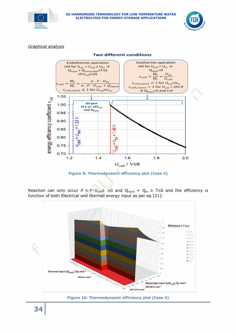
Graphical analysis
Figure 9 Thermodynamic efficiency plot (Case 4)
Reaction can only occur if nmiddotFmiddotUcellge G and Qinput + Qirr ge TS and the efficiency is
function of both Electrical and thermal energy input as per eq [21]
Figure 10 Thermodynamic efficiency plot (Case 4)
3D-plotof vs nFEcell
and Qinput
Endothermic operationIne0 for Urev lt Ucell le Utn rarr
Qinput + QirreversiblegeTSnFUcellgeG
UcellgeUrev
Exothermic operationIne0 for Ucell gt Utn rarr
Qinput=0
UcellgtUtn
rarr Qinput=0 and
Two different conditions
EU HARMONISED TERMINOLOGY FOR LOW TEMPERATURE WATER ELECTROLYSIS FOR ENERGY STORAGE APPLICATIONS
35
Figure 11 Thermodynamic efficiency plot (Case 4)
When Qinput is zero the bi-dimensional plot is equal to that above reported for
case 3 see figure 8
Efficiency is 1 when total energy input (heat and electricity) is 28584 KJ mol-1 This
minimum energy requirement can be supplies as electricity + heat or electricity only
WATER ELECTROLYSIS EFFICIENCY CASES COMPARISON 3735
A comparison of the energy efficiencies for cases 12 and 3 presented above is shown in
figure 12 For any given Ucell it is evident that case 3 provides a higher efficiency values
compared to cases 1 and 2 with a difference of around 15-17 while between case 1
and case 2 the difference of efficiency goes from 0 at Urev up to 5 at 20 V
EU HARMONISED TERMINOLOGY FOR LOW TEMPERATURE WATER ELECTROLYSIS FOR ENERGY STORAGE APPLICATIONS
36
Figure 12 Plots of the energy efficiency Vs Ucell for cases 1 2 and 3
374 ENERGY EFFICIENCY AS FUNCTION OF OPERATING TEMPERATURE
Absolute temperature (T) and pressure (p) are the two main physical variables used to
define the state of the electrolysis cell All thermodynamic functions of interest used to
define the energy efficiency coefficient are functions of (Tp) Therefore it is necessary to
provide an expression of these thermodynamic functions at any (Tp) operating
conditions of interest in order to be able to calculate the efficiency of the electrolyser
(cell stack or system level) at such conditions
Simplified expression of the efficiency versus T at p = 1 bar (105Pa)
For PEM and alkaline electrolysis in a first approximation the enthalpy change of the
water splitting reaction H(Tp) can be considered as constant over the limited
temperature range of interest (0 ndash 100degC) This is shown in Figure 13 H(Tp) is
equal to the standard enthalpy change ∆119919120782 = 119951119917 119932119957119951
120782 Hence the energy efficiency
coefficient cell of a water electrolysis cell or stack can be approximated over this
temperature range by using the SATP reference values for U
119932119955119942119959120782 =123 V and 119932119957119951
120782 = 148 V
EU HARMONISED TERMINOLOGY FOR LOW TEMPERATURE WATER ELECTROLYSIS FOR ENERGY STORAGE APPLICATIONS
37
Figure 13
Thermo-neutral voltage evolution vs temperature liquid water
Expression of the efficiency versus T at p = 1 bar without simplifying
assumption
For a more accurate energy efficiency calculation it is necessary to take into account the
effect of operating temperature Empirical polynomial expressions for calculation of the
thermodynamic voltage Urev(Tp) based on Gibbs free energy change and the thermo-
neutral voltage Utn have been reported in the literature[9] For liquid water conditions in
the range 0 to 100degC and p =1013 105 Pa = 1013 105 bar and up to 200degC with p= 1824∙105 Pa = 1824 bar the expressions are
119880119903119890119907(119879 1119886119905119898) = 2119865 ∆119866(119879) = 15184 minus 15421 ∙ 10minus3 ∙ 119879 + 9523 ∙ 10minus5 ∙ 119879 ∙ 119871119899(119879) + 984 ∙ 10minus81198792 [22]
119880119905119899(119879 1119886119905119898) = 2119865 ∆119867(119879) = 1485 minus 149 ∙ 10minus4 ∙ (119879 minus 1198790) minus 984 ∙ 10minus8 ∙ (119879 minus 1198790)2 [23]
where T is expressed in Kelvin in both cases and T0 = 27315 K It should be noted here
that these two equations are valid for p = 1 atm and not p = 1 bar The difference in
pressure is 1 Therefore Eq [22] and [23] can be used when the pressure is 1 bar
The example of the corrected thermo-neutral voltage value 119880119905119899 as a function of the
reaction temperature at atmospheric pressure is described in Fig 13 (water in the liquid
state) Its value changes from 1481 V at 25degC to 1469 V at 100degC (a variation of only
082 that confirms the above assumption that temperature effect can be neglected in a
first approximation)A similar linear behavior applies to the variation of the cell voltage at
reversible conditions 119880119903119890119907 but with a relatively larger change of around 5 being Urev
1229 V at 25degC and 1167 V at 100degC
375 ENERGY EFFICIENCY AS FUNCTION OF OPERATING PRESSURE
Dry and ideal gases conditions
It should be first noted that only the Gibbs free energy change of the water dissociation
reaction (G) changes with pressure The enthalpy change (H) is constant because the
144
145
146
147
148
149
15
20 30 40 50 60 70 80 90 100
Th
erm
on
eutr
al V
olt
age
V
temperature degC
EU HARMONISED TERMINOLOGY FOR LOW TEMPERATURE WATER ELECTROLYSIS FOR ENERGY STORAGE APPLICATIONS
38
effect of pressure on the free-energy and the entropy changes cancel each other out
Therefore there is a need to provide a definition of the role of pressure on the reference
case (the numerator of Eq [8]) only for case 2 (H is used at the numerator for Cases 1
and 3)
Assuming that the product streams (H2 and O2) at the exhaust of the electrolyser are dry
and ideal gases then the minimal electric energy required to evolve one mole of
hydrogen Wt = ΔGrev(TpI=0) (in JmolH2) can be determined by introducing the
variation ΔUcell of the cell voltage with the pressures of reacting species ( 1199011198672119874 ) and
products (1199011198672 and 1199011198742
) as follows
119899119865 119880119903119890119907(119879 119901) = ∆119866119903119890119907(119879 119901120579) + 119877119879 ln [ (1199011198742
119901120579 )1
2 (1199011198672
119901120579 ) (1199011198672119874
119901120579 )] = 119899119865 (119880119903119890119907(119879 119901120579) + ∆119880119888119890119897119897) [24]
with
∆119880119888119890119897119897 = 119880119903119890119907(119879 119901) minus 119880119903119890119907(119879 119901120579) = 119877119879
2119865ln [ (
1199011198742
119901120579 )1
2 (1199011198672
119901120579 ) (1199011198672119874
119901120579 )] [25]
The different pressures (expressed in bar) in Eqs [24] and [25] have the following
meaning
I 1199011198742 = oxygen partial pressure
I 1199011198672119874 119901120579frasl = 1198861198672119874 = 1 for PEM and alkaline water electrolysis (where aH2O is the
activity of water)
I 1199011198672 = hydrogen partial pressure
I 119901120579 = reference pressure at at the working temperature
In each cell compartment the total pressure p is the sum of partial pressures
I 119901 = sum 119901119894 = 1199011198742+ 1199011198672
+ 1199011198672119874
I pA = pressure of the anodic compartment = p including the presence of some H2
(hydrogen leakage through the separator) and of water vapour
I pC = pressure of the cathodic compartment = p + p assuming a differential
pressure p between the two compartments
Water saturated and ideal gases
Since gases produced during electrolysis are usually saturated with water vapor
equations [24] and [25] need corrections
For ideal wet gases
119899119865119880119903119890119907(119879 119901120579) = ∆119866119903119890119907(119879 119901120579) + 119877119879 ln [ (119901119860minus1199011198672119874
119904119886119905
119901120579 )1
2 (119901119862minus1199011198672119874
119904119886119905
119901120579 ) (1199011198672119874
119904119886119905
119901120579 )] = 2119865(119880119903119890119907(119879 119901120579) + ∆119880119888119890119897119897) [26]
∆119880119888119890119897119897 =119877119879
2119865 ln [ (
119901119860minus1199011198672119874119904119886119905
119901120579 ))1
2 (119901119862minus1199011198672119874
119904119886119905
119901120579 ) (1199011198672119874
119904119886119905
119901120579 )] [27]
where Urev(Tp) is the cell voltage at reference pressure 119901120579 and temperature T and
1199011198672119874119904119886119905 (119879) = water saturation pressure at an operating temperature T
Equi-pressure operation
For pressure values identical at both electrodes (pA = pC = p = 119901120579) and assuming no gas
leakages through the separator it is possible to use a simplified expression of
EU HARMONISED TERMINOLOGY FOR LOW TEMPERATURE WATER ELECTROLYSIS FOR ENERGY STORAGE APPLICATIONS
39
equation [27] to take into account the effect of pressure on the cell voltage Urev derived
from the Nernst equation This simplified expression is given by eq[28]
∆119880119888119890119897119897 = 119880119903119890119907(119879 119901) minus 119880119903119890119907(119879 119901120579) = 119877119879
2119865ln [ (
119901minus1199011198672119874119904119886119905
119901120579)
1
2] [28]
Real and wet gases
Finally to take into account the fact that real gases are produced instead of ideal gases
(large operating pressures above 100 bars) it is necessary to use appropriate state
equations that pertain to real gases (not considered here)
376 ENERGY EFFICIENCY STACK
The energy efficiency of a liquid water electrolysis stack operating at temperature T and
pressure p is equal to the mean energy efficiency of the individual cells multiplied by the
number N of cells in the stack The energy consumption of auxiliaries (Waux) is NOT taken
into account In other words a stack is equivalent to a single cell having a mean cell
voltage value of Ucell = UstackN Therefore all the previous equations used to define the
energy efficiency coefficient prevail the only thing to do is to replace Ucell by UstackN
whenever necessary in these equations
Remark it is also possible to calculate the energy efficiency coefficient of the jth cell in a
stack of N cells by setting
119880119888119890119897119897 = 119880119888119890119897119897119895119905ℎ
[29]
For the case where Ustack is used the corresponding efficiency equations are as follows
Case 1
1205761199041199051198861198881198961198881198861199041198901 =119873middot119880119905119899(119879119901)
119873middot119880119905119899(119879119901)+ 119880119904119905119886119888119896(119879119901)minus119873middot119880119903119890119907(119879119901) [30]
Case 2
1205761199041199051198861198881198961198881198861199041198902 =119873middot119880119903119890119907(119879119901)
119880119904119905119886119888119896(119879119901) [31]
Case 3
When Ucellgt Utn 1205761199041199051198861198881198961198881198861199041198903 =119873middot119880119905119899
119880119904119905119886119888119896 [32]
EU HARMONISED TERMINOLOGY FOR LOW TEMPERATURE WATER ELECTROLYSIS FOR ENERGY STORAGE APPLICATIONS
40
When Urev lt Ucell le Utn 120576119904119905119886119888119896119888119886119904119890 3 =119873middot119899middot119865middot119880119905119899
119873middot119899middot119865middot119880119905119899= 1 [33]
Case 4
120576119904119905119886119888119896119888119886119904119890 4 =119873middot119899middot119865middot119880119905119899
119873middot119899middot119865middot119880119905119899+119876119894119899119901119906119905= 1 [34]
With Ustack = N middot [Ucell(TpI) + ΔUcell] and Qstack the heat balance at the stack level as
derived from [7] ie
Qstack = Nmiddot nmiddotFmiddot (Utn - Ucell) = nmiddotFmiddot (Nmiddot Utn - Ustack) [35]
377 ENERGY EFFICIENCY ndashSYSTEM
At system level the energy consumption of ALL the necessary ancillary equipement (eg
ACDC conversion water purification water pre-heating pumps for water circulation
hydrogen purification hydrogen drying process monitoring etc) used to operate the
electrolyzer are added to the denominator of the equations used for the definition of the
energy efficiency coefficient This terms (Waux for auxiliary equipment in Jmol-1) is added
to the energy requirement in irreversible (I 0) conditions
The efficiency equations for the system is the following
119873 middot119880119905119899(119879119901)
119880119904119905119886119888119896+ 119882119886119906119909 (119899119865)frasl [36]
The heat balance equations for the system is the following
Qsystem =nmiddotFmiddot (Nmiddot Utn - Ustack) + Waux [37]
378 CURRENT EFFICIENCY
CURRENT EFFICIENCY LOSSES 3781
In an ideal water electrolysis cell where membranesseparators are assumed to be
impermeable to gases the current efficiency ε is equal to 100 However materials
(polymer electrolyte of PEM or diaphragm of alkaline) are not fully impermeable Mass
transport of hydrogen andor oxygen across the cell separator especially when the cell is
operated under pressure is an issue that raises both safety and current efficiency
problems Depending on the characteristics of the materials used in the cells a fraction
of the gases transported across the cell separator can react chemically or
electrochemically In conclusion in a water electrolysis cell the current efficiency is less
than 100 due to gas cross-over or permeation effects
EU HARMONISED TERMINOLOGY FOR LOW TEMPERATURE WATER ELECTROLYSIS FOR ENERGY STORAGE APPLICATIONS
41
It is usually difficult to measure accurately the gas flow rates (in moles per second) for
gases permeated through the membrane separator 1198672_119897119900119904119904 and 1198742_119897119900119904119904
because the
hydrogen flow rates could be relatively small (at single cell and short stack laboratory
tests) containing water vapour residues and as already mentioned due to the cross-over
and permeation effects some hydrogen and oxygen can react together and produce water
before the measurement procedure
CURRENT EFFICIENCY ndash SINGLE CELL 3782
This is the fraction of the electric current passing through an electrochemical cell which
accomplishes the desired chemical reaction For a set of cell components and for a given cell design the current efficiency 120520119816 is mainly a function of operating temperature T
operating pressure p and operating current density
η119868(119879 119901 119868) = 1 minus2 ∙ 119865
119868119863119862∙ [1198672_loss
(119879 119901 119868) + 21198742_loss(119879 119901 119868)] [38]
where 119894 is the molar flow of component (i) permeated through the membrane separator
in mole per second 2 is the number of Faraday per mole of H2 and 4 per mole of O2 and
IDC the direct current provided expressed in Ampere In an ideal water electrolysis cell 1198672_119897119900119904119904
= 1198742_119897119900119904119904= 0 and η
119868(119879 119901 119868) = 1 independently of
the operating conditions (TpI)
In a real water electrolysis cell 1198672_119897119900119904119904 ne 1198742_119897119900119904119904ne 0 and η
119868(119879 119901 119868) lt 1
In practical conditions it is easier and more accurate to measure the hydrogen or the
oxygen flow rates at the exhaust of the electrolyser instead of measuring H2 and O2
cross-permeating flows which are in many cases extremely small Then equation [39]
(for hydrogen production) or [40] (for oxygen production) apply
1205781198681198672 =
119898119890119886119904119906119903119890119889 1198672 119891119897119900119908 119903119886119905119890
119905ℎ119890119900119903119890119905119894119888119886119897 1198672 119891119897119900119908 119903119886119905119890=
2 ∙ 119865 ∙ 1198672 119898119890119886119904119906119903119890119889
119868119863119862 [39]
1205781198681198742 =
119898119890119886119904119906119903119890119889 1198742 119891119897119900119908 119903119886119905119890
119905ℎ119890119900119903119890119905119894119888119886119897 1198742 119891119897119900119908 119903119886119905119890=
4 ∙ 119865 ∙ 1198742 119898119890119886119904119906119903119890119889
119868119863119862 [40]
The measurement of the relevant outlet gas hydrogen or oxygen shall be performed
using a properly dimensioned and highly accurate mass flow meter placed after the water
removal steps that shall be designed to remove more than 999 of gas water content
Concentration of hydrogen in oxygen should be measured by gas chromatographic
analysis or via other analytical techniques with similar detection limit after a gas drying
step The molar fraction of the components in the outlet gases should be also measured
but in normal conditions it is assumed that traces of oxygen and water vapour in
hydrogen or hydrogen and water vapour in oxygen are minor and thus usually negligible
In case of high differential pressures and thin membranes (50 to 90 microm) instead current
efficiency of about 98 or even lower can be observed Nevertheless safety sensors to
monitor oxygen level in hydrogen outlet or hydrogen level in oxygen outlet are strongly
recommended to detect dangerous situations due to gas cross-over of the separator
EU HARMONISED TERMINOLOGY FOR LOW TEMPERATURE WATER ELECTROLYSIS FOR ENERGY STORAGE APPLICATIONS
42
CURRENT EFFICIENCY - STACK 3783
The stack current efficiency at the operation temperature and pressure is defined as the ratio between the flow rate of the produced hydrogen 1198672
expressed in mole per second
multiplied by the Faraday constant and the provided direct current 119868119863119862 expressed in
Ampere multiplied by the number of cells N It is expressed as follows
120578119868 1199041199051198861198881198961198672 =
119898119890119886119904119906119903119890119889 1198672 119891119897119900119908 119903119886119905119890
119905ℎ119890119900119903119890119905119894119888119886119897 1198672 119891119897119900119908 119903119886119905119890=
2 ∙ 119865 ∙ 1198672 119898119890119886119904119906119903119890119889
119873 119868119863119862 [41]
120578119868 1199041199051198861198881198961198742 =
119898119890119886119904119906119903119890119889 1198742 119891119897119900119908 119903119886119905119890
119905ℎ119890119900119903119890119905119894119888119886119897 1198742 119891119897119900119908 119903119886119905119890=
4 ∙ 119865 ∙ 1198742 119898119890119886119904119906119903119890119889
119873 119868119863119862 [42]
COULOMBIC AND FARADIC EFFICIENCIES 3784
These expressions have the same meaning as current efficiency
379 TOTAL EFFICIENCY ndash SINGLE CELL AND STACK
The total efficiency ηω is defined as the product of energy efficiency and current
efficiency values It can be applied at single cell or stack level
120578120596119888119890119897119897 = 120576119888119890119897119897 ∙ 120578119868
119888119890119897119897 [43]
120578120596119904119905119886119888119896 = 120576119904119905119886119888119896 ∙ 120578119868
119904119905119886119888119896 [44]
3710 ENERGY EFFICIENCY DEFINITION INDUSTRYrsquos VIEWPOINT
ENERGY EFFICIENCY COEFFICIENT 37101
As already discussed at the beginning of this document (section 371) the reference
energy state used by the industry sector to define the energy efficiency coefficient of a
water electrolysis cell stack or system is different from the reference case used by the
academic community The general definition is
120578119888119890119897119897 =119890119899119890119903119892119910 119888119900119899119905119890119899119905 119900119891 119901119903119900119889119906119888119905119904
119905119900119905119886119897 119890119899119890119903119892119910 119903119890119902119906119894119903119890119898119890119899119905119904=
119882119905 (119869119898119900119897minus1)
119882119903 (119869119898119900119897minus1) [B]
The energy content of products used at the numerator of the equation is usually the
hydrogen heating value in oxygen (not in air) which is by definition the opposite of the
standard enthalpy of formation of a water molecule HHV = ΔH0 = 2858 kJ mol-1 There
are potentially different practices that will inevitably lead to different values of the energy
efficiency coefficient In order to facilitate comparison it is necessary to list these
different practices
EU HARMONISED TERMINOLOGY FOR LOW TEMPERATURE WATER ELECTROLYSIS FOR ENERGY STORAGE APPLICATIONS
43
Some authors use the heating value of hydrogen combustion in air instead of
oxygen
Some authors use the High Heating Value of hydrogen combustion in oxygenair
(leading to the formation of liquid water) and some other use the Low Heating
Value (LHV)of hydrogen combustion in oxygenair (leading to the formation of
gaseous water)
Authors use different (Tp) conditions to calculate the energy content of their
product
The usual practice in industry is not to calculate the efficiency coefficient in
percent (as in the academic community) but instead to calculate the specific
energy consumption of a system (eg in kWhkgH2 or in kWhNm3H2)
The reason for such discrepancies is clear the reference state is not unique but dictated
by the applications Therefore the same electrolyser when used for different applications
can have different efficiencies Hence there is a need to provide clear specifications to
allowing comparisons
The main issue is to specify the (Tp) conditions at which the reference energy content of
hydrogen is calculated These (Tp) conditions could be considered at the exhaust of the
electrolysis cell stack or the (Tp) conditions at the exhaust of the plant after gas
treatment (oxygen removal drying and eventually compression)
Specifically the instantaneous hydrogen production efficiency (based on the HHV) is
defined as the ratio between the flow rate of the produced hydrogen H2 expressed in
mole per second multiplied by the HHV expressed in Joule per mole of hydrogen and the
total thermal and electric power provided to the system expressed in Watt ie
η119867119867119881 =119867119867119881 ∙ 1198672
119875119905ℎ119890119903119898119886119897 + 119875119890119897119890119888119905119903119894119888119886119897 [45]
Equation [45] provides a practical and general (energy + current) value of the efficiency
An integral form of Eq [45]middot is needed to determine the specific energy consumption in
kWhkgH2 When the system is operated under stationary conditions the expression
(over a given time interval t) is simply
η119867119867119881 =119867119867119881 ∙ 1198672
∙ t
119882119890 + 119876119888119890119897119897 + 1198761198672119874 =
119867119867119881 ∙ 1198731198672
119882119890 + 119876119888119890119897119897 + 1198761198672119874 [46]
where
1198672 is the number of moles of hydrogen produced over time (molar flow rate)
1198731198672 is the number of moles of hydrogen produced over the time period t
considered
We = nF Ucell is the electric energy input
Qcell is the difference between the entropy change (TΔS) and the heat Qirrev
associated with irreversible losses due to overvoltages of the electrochemical
reactions and Joule effect in the internal resistance
QH20 is the thermal energy input of additional heat exchanger (external to the
system) for further water heat up
EU HARMONISED TERMINOLOGY FOR LOW TEMPERATURE WATER ELECTROLYSIS FOR ENERGY STORAGE APPLICATIONS
44
OVERALL COMPONENT EFFICIENCY 37102
Component efficiency for the HHV is defined as the ratio between the flow rate of the produced hydrogen nH2
expressed in mole per second multiplied by the HHV expressed
in Joule per mole and the total thermal and electric power provided to the component
expressed in Watt as follows
η119888119900119898119901119900119899119890119899119905119867119867119881 =
119867119867119881
119875119888119900119898119901119900119899119890119899119905 119890119909119905119890119903119899∙ 1198672
[47]
OVERALL SYSTEM EFFICIENCY 37103
At system level (Stack + BoP) it is necessary to take into account the energy
consumption of all the necessary ancillary equipment System efficiency for the HHV is
defined as the ratio between the flow rate of the produced hydrogen nH2 expressed in
mole per second multiplied by the HHV expressed in Jmol-1 and the total thermal and
electric power supplied to the system for the operation of all ancillary equipment
expressed in Watt It is expressed in percentage as
η119904119910119904119905119890119898119867119867119881 =
119867119867119881
119875119904119910119904119905119890119898 119890119909119905119890119903119899∙ 1198672
[48]
OTHER EXPRESSIONS OF PRACTICAL INTEREST 37104
Some authors also calculate the energy efficiency coefficient of the system by multiplying
the stack efficiency (assuming a current efficiency of 1) by the ACDC conversion
efficiency (in this case the reference case is the enthalpy change of the reaction = case
3 of the definition used in the academic community and the efficiency of gas conditioning
is not taken into account)
120576119904119910119904119905119890119898 =119873 middot 119880119905119899(119879 119901)
119880119904119905119886119888119896
This definition contains the same eq[32] in case 3 under exothermal operation
multiplied by the ACDC conversion efficiency
120576119904119910119904119905119890119898 =119873 middot 119880119905119899(119879 119901)
119880119904119905119886119888119896 (
119860119862119863119862
1 + ) [49]
In Eq [49] is the ratio between parasitic power and net power consumed by the
electrolyser due to the energy consumption by the auxiliaries
ACDC = efficiency of the ACDC converter DCDC voltage regulator or power conditioner
Another equation of practical interest is obtained from Eq [49] by taking into account
the hydrogen current efficiency(10)
EU HARMONISED TERMINOLOGY FOR LOW TEMPERATURE WATER ELECTROLYSIS FOR ENERGY STORAGE APPLICATIONS
45
120576119904119910119904119905119890119898 =119873 middot 119880119905119899(119879 119901)
119880119904119905119886119888119896middot
2 ∙ 119865 ∙ 1198672
119868119863119862 ∙ 119873middot (
119860119862119863119862
1 + ) [50]
EU HARMONISED TERMINOLOGY FOR LOW TEMPERATURE WATER ELECTROLYSIS FOR ENERGY STORAGE APPLICATIONS
46
3711 EXERGY ANALYSIS
EXERGY DEFINITION 37111
In general terms Exergy can be defined as the maximum work that can be extracted
when a system is brought into equilibrium with its surroundings without incurring any
losses (Wall 1977) The efficiency of a process is defined as the used exergy outflow
divided by the used exergy inflow The term Yield is brought together with the Exergy
to replace the term Efficiency to avoid confusion between Energy and Exergy efficiency
descriptors
Field of application
bull The water splitting reaction (chemical reaction) is analysed at constant (TpI)
conditions only the transformation takes place in a thermostatic reactor the heat
needed to bring tap water up to the operating temperature of interest is not taken into
account in the efficiency calculation and the reaction products (H2 and O2) are considered
at the same (Tp) conditions
bull The water electrolysis cell (device) is also analysed at constant (TpI) conditions
but the heat needed to bring tap water up to the operating temperature of interest is
taken into account in the efficiency calculation and the (Tp) of product gases may differ
from those of the reaction
The water electrolysis cell stack and plant are thermodynamically open systems
operating in either stationary or non-stationary conditions The exergy balance can be established in integral form (J) or in power (Jmiddots-1) or in specific power (Jmiddots-1
middotm-2) The
exergy yield relates the exergy output to the exergy input Due to internal irreversible
degradations (mainly dissipation at cell and stack levels) the exergy output is less than
the exergy input and the exergy yield is less than unity To calculate the exergy yield it
is necessary to take into account the different exergy contributions
bull The work or work-power received from the DC power source (the exergy content
of 1 Joule of electricity is equal to 1 Joule)
bull The heat-exergy (the heat-exergy power or flow rate) associated with heat
transfers (the exergy content of 1 Joule of heat is modulated by the associated Carnot
factor)
bull The transformation-exergy (the transformation-exergy power or flow rate)
associated with the chemical reaction This is the co-enthalpy balance of the water
splitting reaction
∆119896 = sum 120584119894[(ℎ minus ℎ1198940) minus 119879119890119899119907(119904119894 minus 119904119894
0)]
119894
[46]
Where
120584119894 = generalized stoichiometric reaction number
ℎ = enthalpy at operating condition
ℎ1198940 = enthalpy at reference condition
119879119890119899119907 = ambient temperature
EU HARMONISED TERMINOLOGY FOR LOW TEMPERATURE WATER ELECTROLYSIS FOR ENERGY STORAGE APPLICATIONS
47
119904119894 = entropy at operating condition
1199041198940 = entropy at reference condition
The exergy yield can be defined starting from the overall efficiency formula used in the
industry Eq [45] that takes into account the energy content of the hydrogen production
and the electrical and thermal energy inputs as(7)
120577119867119867119881 =119864119867119867119881 ∙ 1198672
119890 + 119902119888119890119897119897 (1 minus119879119890119899119907
119879119888119890119897119897 ) + 1199021198672119874(1 minus
119879119890119899119907
119879119888119890119897119897 )
[52]
where
ζHHV is the exergy yield of the water splitting reaction
EHHV in Jmole is the molar exergy value associated with the hydrogen production at
(TcellPcell) conditions (based on the HHV reaction because liquid water is electrolysed in a
PEM water electrolysis cell) The value is very close to the energy content
nH2 in mols is the molar hydrogen flow
Ee in Js is the electricity exergy input from the DC power source
Eqcell in Js is the exergy input to the PEM cell for the reaction
Tenv in K is the temperature of the environment (ambient)
Tcell in K is the operating temperature of the electrolysis cell
EqH2O in Js is the exergy content of input water that is heated up from ambient to the
operating temperature
RELATION BETWEEN ENERGY EFFICIENCY AND EXERGY 37112
YIELD
Since PEM AEM and alkaline water electrolysis cells operate in near-ambient operating conditions the exergy content of the heat flows (Eqcell and EqH2O) is small because Tcell asymp
Tenv In this condition when an electrolyser operates in exothermic mode the only
thermal energy needed is for the heating of water added to the system to replace the
one converted into hydrogen and oxygen Therefore the main type of energy supplied to
the system is the electrical one and as electricity has 100 exergy content the energy
efficiency and exergy yield are close
Also the heat produced by a water electrolysis plant operating in near-ambient
conditions has a low exergy value and cannot be used for work production It is
considered as a loss and can be used only for heating purposes
This is why an energy analysis is considered as sufficient to determine the characteristics
of a water electrolysis cell or stack operating in such near-ambient conditions The
situation is different for a high temperature water electrolysis cell but this analysis it is
not considered in this account At system level it is important to evaluate the exergy
yield contribution by the different BoP components in order to obtain the total exergy
yield of the system
EU HARMONISED TERMINOLOGY FOR LOW TEMPERATURE WATER ELECTROLYSIS FOR ENERGY STORAGE APPLICATIONS
48
3712 SUMMARY TABLES OF EQUATIONS
The following Tables provide a summary of the various efficiency equations presented in
this document
Table 2
ENERGY EFFICIENCY
ENERGY EFFICIENCY - 120634
SINGLE CELL NOTE Eq No
119932119955119942119959120782
= ΔG0(n F) 1229V at SATP [3]
119932119955119942119959(119931 120783119938119957119950) = 120783 120787120783120790120786 minus 120783 120787120786120784120783 ∙ 120783120782minus120785 ∙ 119931 + 120791 120787120784120785 ∙ 120783120782minus120787
∙ 119931 ∙ 119923119951(119931) + 120791 120790120786 ∙ 120783120782minus120790119931120784
Urev in the
temperature range
0-100degC
[22]
119932119957119951120782
= ΔH0(n F) 1481V at SATP [4]
119932119957119951(119931 120783119938119957119950) = 120783 120786120790120787 minus 120783 120786120791 ∙ 120783120782minus120786 ∙ (119931 minus 119931120782) minus 120791 120790120786 ∙ 120783120782minus120790
∙ (119931 minus 119931120782)120784
Utn in the
temperature range
0-100degC
[23]
120634119940119942119949119949119940119938119956119942120783 =119932119957119951
119932119957119951 + 119932119940119942119949119949 minus 119932119955119942119959
Case 1
Constant heat input-
based definition
[9]
120634119940119942119949119949119940119938119956119942120783 =119932119957119951(119931 119953)
119932119957119951(119931 119953) + 119932119940119942119949119949(119931 119953) minus 119932119955119942119959(119931 119953)
Case 1
For any Tp
condition
[11]
120634119940119942119949119949119940119938119956119942120784 = 119932119955119942119959
119932119940119942119949119949
Case 2
Free energy-based
definition
[12]
120634119940119942119949119949119940119938119956119942120784(119931 119953) =119932119955119942119959(119931 119953)
119932119940119942119949119949(119931 119953)
Case 2
For any Tp
condition
[14]
120634119940119942119949119949119940119938119956119942120785 =119951 middot 119917 middot 119932119957119951
119951 middot 119917 middot 119932119957119951
Case 3 120576 = 1
When Urev lt Ucell le
Utn
[15]
[16]
120634119940119942119949119949119940119938119956119942120785 =119932119957119951
119932119940119942119949119949
Case 3
Enthalpy-based
definition when
[17]
EU HARMONISED TERMINOLOGY FOR LOW TEMPERATURE WATER ELECTROLYSIS FOR ENERGY STORAGE APPLICATIONS
49
UcellgtUtn
120634119940119942119949119949119940119938119956119942120785 =119932119957119951 (119931 119953)
119932119940119942119949119949 (119931 119953)
Case 3 when
UcellgtUtn
For any Tp
condition
[18]
120634119940119942119949119949119940119938119956119942120786 =119951 middot 119917 middot 119932119957119951
119951 middot 119917 middot 119932119940119942119949119949 + 119928119946119951119953119958119957 Case 4 [21]
∆119932119940119942119949119949 =119929119931
120784119917 119845119847 [ (
119953119912 minus 119953119919120784119926119956119938119957
119953120637)
120783120784 (
119953119914 minus 119953119919120784119926119956119938119957
119953120637 ) (119953119919120784119926
119953120637 )]
Water saturated and
ideal gases pressure
correction voltage
[27]
Qcell = nmiddotFmiddot(Utn - Ucell)
Cell heat balance
Qcell lt 0 rejected
Qcell gt 0 absorbed
[7]
STACK
120634119956119957119938119940119948119940119938119956119942120783 =119925 middot 119932119957119951(119931 119953)
119925 middot 119932119957119951(119931 119953) + 119932119956119957119938119940119948(119931 119953) minus 119925 middot 119932119955119942119959(119931 119953) Case 1 [30]
120634119956119957119938119940119948119940119938119956119942120784 =119925 middot 119932119955119942119959(119931 119953)
119932119956119957119938119940119948(119931 119953) Case 2 [31]
120634119956119957119938119940119948119940119938119956119942 120785 =119925 middot 119932119957119951
119932119956119957119938119940119948
Case 3 when
Ucellgt Utn [32]
120634119956119957119938119940119948119940119938119956119942120785 =119925middot119951middot119917middot119932119957119951
119925middot119951middot119917middot119932119957119951 = 1
Case 3 when
Urev lt Ucell le Utn [33]
120634119940119942119949119949119940119938119956119942120786 =119951 middot 119917 middot 119932119957119951
119925 middot 119951 middot 119917 middot 119932119940119942119949119949 + 119928119946119951119953119958119957 119956119957119938119940119948
Case 4 when
Urev lt Ucell lt Utn [34]
Qstack = nmiddotFmiddot(NmiddotUtn - Ustack)
Stack heat balance
Qstack lt 0 rejected
Qstack gt 0 absorbed
[35]
SYSTEM
119925 119932119957119951(119931 119953)
119932119956119957119938119940119948 + 119934119938119958119961 (119951119917)frasl System efficiency [36]
EU HARMONISED TERMINOLOGY FOR LOW TEMPERATURE WATER ELECTROLYSIS FOR ENERGY STORAGE APPLICATIONS
50
Table 3
CURRENT EFFICIENCY
Table 4
OVERALL EFFICIENCY
Qsystem = nmiddotFmiddot(N middotUtn - Ustack) + Waux Heat balance [37]
CURRENT EFFICIENCY - 120636119920
SINGLE CELL NOTE Eq No
120520119920(119931 119927 119920) = 120783 minus120784 ∙ 119917
119920119915119914
∙ [119919120784_119845119848119852119852(119931 119953 119920) + 120784119926120784_119845119848119852119852
(119931 119953 119920)]
General formula
(academic viewpoint) [38]
120636119920119919120784 =
120784 119917 119919120784 119950119942119938119956119958119955119942119941
119920119915119914
Hydrogen production
efficiency
(industry viewpoint)
[39]
120636119920119926120784 =
120786 119917 119926120784 119950119942119938119956119958119955119942119941
119920119915119914
Oxygen production
efficiency
(industry viewpoint)
[40]
STACK
120520119920119956119957119938119940119948119919120784 =
120784 ∙ 119917 ∙ 119919120784
119920119915119914 ∙ 119925
Hydrogen production
efficiency
(industry viewpoint)
[41]
120520119920119956119957119938119940119948119926120784 =
120786 ∙ 119917 ∙ 119926120784
119920119915119914 119925
Oxygen production
efficiency
(industry viewpoint)
[42]
OVERALL EFFICIENCY - 120520120538
SINGLE CELL NOTE Eq No
EU HARMONISED TERMINOLOGY FOR LOW TEMPERATURE WATER ELECTROLYSIS FOR ENERGY STORAGE APPLICATIONS
51
Table 5
EXERGY YIELD1
120636120654119940119942119949119949 = 120634119940119942119949119949 ∙ 120636119920
119940119942119949119949 Total efficiency
(academic viewpoint) [43]
120520119919119919119933 =119919119919119933 ∙
119927119957119945119942119955119950119938119949 + 119927119942119949119942119940119957119955119946119940119938119949∙ 119919120784
Instantaneous cell
efficiency
(industry viewpoint)
[45]
120520119919119919119933 =119919119919119933 ∙ 119919120784
∙ 119853
119934119942 + 119928119940119942119949119949 + 119928119919120784119926
Integral form of cell
efficiency (stationary
operating conditions)
[46]
STACK
120636120654119956119957119938119940119948 = 120634119956119957119938119940119948 ∙ 120636119920
119956119957119938119940119948 Total efficiency
(academic viewpoint) [44]
COMPONENT
120520119940119952119950119953119952119951119942119951119957119919119919119933 =
119919119919119933
119927119940119952119950119953119952119951119942119951119957 119942119961119957119942119955119951
119919120784 Component efficiency [47]
SYSTEM
120520119956119962119956119957119942119950119919119919119933 =
119919119919119933
119927119956119962119956119957119942119950 119942119961119957119942119955119951
∙ 119919120784
System efficiency
(industry viewpoint) [48]
120634119956119962119956119957119942119950 =119925 middot 119932119957119951(119931 119953)
119932119956119957119938119940119948 (
119912119914119915119914
120783 + )
System efficiency
excluding faradaic
efficiency
(industry viewpoint)
[49]
120634119956119962119956119957119942119950 =119925 middot 119932119957119951(119931 119953)
119932119956119957119938119940119948middot
120784 ∙ 119917 ∙ 119919120784
119920119915119914 ∙ 119925middot (
119912119914119915119914
120783 + )
System efficiency
including faradaic
efficiency
(industry viewpoint)
[50]
EXERGY YIELD - 120635119919119919119933
SINGLE CELL NOTE Eq No
EU HARMONISED TERMINOLOGY FOR LOW TEMPERATURE WATER ELECTROLYSIS FOR ENERGY STORAGE APPLICATIONS
52
1Exergy Yield expressions for Components and Systems are not covered in this report
3713 REVERSIBLE POTENTIAL (Erev)
It is defined as the minimum necessary cell voltage needed to start the water electrolysis
as in eq [3]
At SATP conditions it is expressed as Edeg and its value is 1229 V
3714 REVERSIBLE VOLTAGE (Vrev)
See equivalent definition of reversible potential 3713
3715 THERMONEUTRAL POTENTIAL (Etn)
The thermoneutral potential at standard conditions (25degC and 1013 hPa) is 1481 V It is
defined as the voltage at which an electrolysis cell operating at 25 degC can operate
without producing excess heat see eq [4]
3716 THERMONEUTRAL VOLTAGE (vtn)
See equivalent definition of thermoneutral potential 3715
120635119919119919119933 =119916119919119919119933 ∙ 119919120784
119942 + 119954119940119942119949119949 (120783 minus119931119942119951119959
119931119940119942119949119949 ) + 119954119919120784119926(120783 minus
119931119942119951119959
119931119940119942119949119949 )
[52]
EU HARMONISED TERMINOLOGY FOR LOW TEMPERATURE WATER ELECTROLYSIS FOR ENERGY STORAGE APPLICATIONS
53
ELECTRICAL POWER 38
381 CELL ELECTRICAL POWER DENSITY
Input power per cell cross section [Units Wm2]
382 ELECTRICAL POWER ndashAPPARENT
The square root of the sum of the squares of the active and the reactive powers(4)
383 ELECTRICAL POWER ndashREACTIVE
For sinusoidal quantities in a two-wire circuit the product of the voltage the current and
the sine of the phase angle between them In a multiphase circuit the sum of the
reactive powers of the phases(4)
384 ELECTRICAL POWER ndashREAL
For sinusoidal quantities in a two-wire circuit the product of the voltage the current and
the cosine of the phase angle between them In a multiphase circuit the sum of the
active powers of the individual phases(4)
385 ELECTRICAL POWER FACTOR
The ratio of the total active power in Watts to the total apparent power in Volt-Amperes
(the product of root-mean-square (rms) voltage and rms Current)
Leading A designation of the relative instantaneous direction of the currents to the
voltages (angle is 0 to ndash90deg)
Lagging A designation of the relative instantaneous direction of the currents to the
voltages (angle is 0 to +90deg)(4)
386 ELECTRICAL POWER INPUT RATED OR NOMINAL
Maximum continuous electric input power that a device is designed to achieve under
normal operating conditions specified by the manufacturer [Units W]
387 PARASITIC LOAD
Power consumed by auxiliary machines and equipment such as balance of plant (BOP)
necessary to operate an electrolyser system [Units W](2)
[Source modified from IEC TS 62282-12013 Fuel cell technologies - Part 1]
EU HARMONISED TERMINOLOGY FOR LOW TEMPERATURE WATER ELECTROLYSIS FOR ENERGY STORAGE APPLICATIONS
54
388 POWER SYSTEM CAPACITY ndash RATED
Maximum capacity of the system in terms of power as rated by the manufacturer
[Units kW or MW]
389 POWER STACK CAPACITY ndash RATED
Maximum stack capacity in terms of electrical DC power as rated by the manufacturer
(kW direct current) [Units kW or MW]
3810 POWER SUPPLY RANGE
It is the functional range of an electrolysis system between its minimum power operating
value and 100 (full scale) rated power DC charge
3811 RATED POWER
The value stated on the device nameplate It is the power to be provided at the input
terminals of a component or piece of equipment that is operated in compliance with the
manufacturerrsquos performance specifications(4)
GAS CROSSOVER 39
Gas permeation through the separation membrane leading to transport of hydrogen to
oxygen side and vice versa leading to safety and efficiency reduction issues
The phenomenon is due to various transport mechanism differential pressure diffusion
electro-osmotic drag ions flux densities
GAS LEAKAGE 310
The sum of all gases leaving the electrolyser module except the intended exhaust
gases(2)
[Source modified from IEC TS 62282-12013 Fuel cell technologies - Part 1]
GAS TIGHTNESS 311
System characteristic that ensures that no exchange of fluids and gases between two or
more compartments of a device occurs ie between anode and cathode or surrounding
space(4)
GRID OR ELECTRICITY NETWORK 312
It is a plant and apparatus connected together for transmitting or distributing electricity (3)
EU HARMONISED TERMINOLOGY FOR LOW TEMPERATURE WATER ELECTROLYSIS FOR ENERGY STORAGE APPLICATIONS
55
3121 BALANCE REGULATION
Balance regulation is the regulation actions done in order to maintain the frequency and
time deviation of the electricity grid in accordance with the set quality requirements
Regulation is also carried out for network reasons
3122 CONNECTION POINT
It is the interface at which the power-generating module demand facility distribution
system is connected to a transmission system offshore network distribution system
including closed distribution systems as identified in the connection agreement between
relevant system operator and either power-generating or demand facility owner (3)
3123 CONTROL AREA
A coherent part of the interconnected system operated by a single system operator and
shall include connected physical loads andor generation units if any (5)
[source ENTSOE glossary]
3124 CONTROL RESERVE
Energy stock to be used to control the frequency of the power supply network in case of
unpredictable variations in energy injection and withdrawal
The reserve can be either positive in order to balance deficits of the network or
negative in case of surplus balance
3125 DISTRIBUTION SYSTEM
The transport of electricity on high-voltage medium-voltage and low-voltage distribution
systems with a view to its delivery to customers but does not include supply(5)
[source ENTSOE glossary]
3126 DISTRIBUTION NETWORK
An electrical Network including Closed Distribution Networks for the distribution of
electrical power from and to third party[s] connected to it a Transmission or another
Distribution Network(5)
[source ENTSOE glossary]
3127 DISTRIBUTION NETWORK OPERATOR
Either a Distribution System Operator or a Closed Distribution System Operator(5)
[source ENTSOE glossary]
EU HARMONISED TERMINOLOGY FOR LOW TEMPERATURE WATER ELECTROLYSIS FOR ENERGY STORAGE APPLICATIONS
56
3128 DISTURBANCE
An unplanned event that may cause the transmission system to divert from the normal
state(5)
[source ENTSOE glossary]
3129 ENERGY FROM RENEWABLE SOURCES
Energy from renewable non-fossil sources namely wind solar aerothermal geothermal
hydrothermal and ocean energy hydropower biomass landfill gas sewage treatment
plant gas and biogases (5)
[source ENTSOE glossary]
31210 ENERGY STORAGE
A device being used for storage of electrical energy and that can be used to balance the
system(5)
[source ENTSOE glossary]
31211 ELECTRICAL TIME DEVIATION
The time discrepancy between synchronous time and coordinated universal time (UTC)
(5)
[source ENTSOE glossary]
31212 ELECTRICAL SYSTEM FREQUENCY
The electric frequency of the system expressed in hertz that can be measured in all parts
of the synchronous area under the assumption of a consistent value for the system in the
time frame of seconds with only minor differences between different measurement
locations Its nominal european value is 50Hz(5)
[source ENTSOE glossary]
31213 FREQUENCY CONTROL
The capability of a power generating module or HVDC system to adjust its active power
output in response to a measured deviation of system frequency from a setpoint in order
to maintain stable system frequency (35)
31214 LOAD-FREQUENCY CONTROL AREA
A part of a synchronous area or an entire synchronous area physically demarcated by
points of measurement at interconnectors to other LFC areas operated by one or more
TSOs fulfilling the obligations of load-frequency control(5)
[source ENTSOE glossary]
EU HARMONISED TERMINOLOGY FOR LOW TEMPERATURE WATER ELECTROLYSIS FOR ENERGY STORAGE APPLICATIONS
57
31215 FREQUENCY CONTROLLED NORMAL OPERATION RESERVE
The frequency controlled normal operation reserve is the momentarily available active
power for frequency regulation in the range of 499 ndash 501 Hz and which is activated
automatically by the system frequency
31216 FREQUENCY CONTAINEMENT RESERVES (FCR)
The active power reserves available to contain system frequency after the occurrence of
an imbalance(5)
[source ENTSOE glossary]
31217 FREQUENCY CONTAINEMENT RESERVES FULL ACTIVATION
FREQUENCY DEVIATION
The rated value of frequency deviation at which the FCR in a synchronous area is fully
activated(5)
[source ENTSOE glossary]
31218 FREQUENCY RESPONSE DEADBAND
An interval used intentionally to make the frequency control unresponsive(5)
[source ENTSOE glossary]
31219 FREQUENCY DEVIATION
The difference between the actual and the nominal frequency of the synchronous area
which can be negative or positive(5)
[source ENTSOE glossary]
INSTANTANEOUS FREQUENCY DEVIATION 312191
A set of data measurements of the overall system frequency deviations for the
synchronous area with a measurement period equal to or shorter than one second used
for system frequency quality evaluation purposes (5)
[source ENTSOE glossary]
MAXIMUM INSTANTANEOUS FREQUENCY DEVIATION 312192
The maximum expected absolute value of an instantaneous frequency deviation after the
occurrence of an imbalance equal to or smaller than the reference incident beyond which
emergency measures are activated(5)
[source ENTSOE glossary]
EU HARMONISED TERMINOLOGY FOR LOW TEMPERATURE WATER ELECTROLYSIS FOR ENERGY STORAGE APPLICATIONS
58
MAXIMUM STEADY-STATE FREQUENCY DEVIATION 312193
The maximum expected frequency deviation after the occurrence of an imbalance equal
to or less than the reference incident at which the system frequency is designed to be
stabilised(5)
[source ENTSOE glossary]
STEADY-STATE FREQUENCY DEVIATION 312194
The absolute value of frequency deviation after occurrence of an imbalance once the
system frequency has been stabilised(5)
[source ENTSOE glossary]
31220 FREQUENCY RESTORATION CONTROL ERROR
The control error for the FRP which is equal to the ACE of a LFC area or equal to the
frequency deviation where the LFC area geographically corresponds to the synchronous
area(5)
[source ENTSOE glossary]
31221 FREQUENCY RESTORATION PROCESS
A process that aims at restoring frequency to the nominal frequency and for
synchronous areas consisting of more than one LFC area a process that aims at
restoring the power balance to the scheduled value(5)
[source ENTSOE glossary]
FREQUENCY RESTORATION RESERVES (FRR) 312211
The Active Power Reserves available to restore System Frequency to the Nominal
Frequency and for Synchronous Area consisting of more than one Load Frequency
Control (LFC) Area to restore power balance to the scheduled value(5)
[source ENTSOE glossary]
AUTOMATIC FREQUENCY RESTORATION RESERVES A-FRR 312212
FRR that can be activated by an automatic control device(5)
[source ENTSOE glossary]
AUTOMATIC FRR FULL ACTIVATION TIME 312213
The time period between the setting of a new setpoint value by the frequency restoration
controller and the corresponding activation or deactivation of automatic FRR(5)
[source ENTSOE glossary]
EU HARMONISED TERMINOLOGY FOR LOW TEMPERATURE WATER ELECTROLYSIS FOR ENERGY STORAGE APPLICATIONS
59
MANUAL FREQUENCY RESTORATION RESERVES MFRR 312214
FRR that can be activated manually
31222 FREQUENCY RESTORATION RANGE
The system frequency range to which the system frequency is expected to return in the
GB IENI and Nordic synchronous areas after the occurrence of an imbalance equal to
or smaller than the reference incident within the time to restore frequency (5)
[source ENTSOE glossary]
31223 FREQUENCY SETPOINT
The frequency target value used in the FRP defined as the sum of the nominal system
frequency and an offset value needed to reduce an electrical time deviation(5)
[source ENTSOE glossary]
31224 FULL ACTIVATION TIME
The time period between the activation request by TSO and the corresponding full
activation of the concerned product(5)
[source ENTSOE glossary]
31225 GRID-CONNECTED OPERATION
Mode when the system is operated while connected to a utility grid
31226 GRID-CONTROL
In the event of a major load fluctuation such as a power station outage or other
unpredictable variations in energy injection and withdrawal in the grid a set of different
control reserve primary secondary and tertiary can be activated at different ramp rates
and time steps as described in the below figure 11
EU HARMONISED TERMINOLOGY FOR LOW TEMPERATURE WATER ELECTROLYSIS FOR ENERGY STORAGE APPLICATIONS
60
Figure 11
Grid control sequence of activation
REPLACEMENT RESERVES 312261
The active power reserves available to restore or support the required level of FRR to be
prepared for additional system imbalances including operating reserves (5)
[source ENTSOE glossary]
RESERVES REPLACEMENT PROCESS 312261
A process to restore the activated FRR and additionally for GB and IENI to restore the
activated FCR(5)
[source ENTSOE glossary]
PRIMARY CONTROL RESERVE 312262
It is the first and fastest control stock reserve to be used in case of grid frequency
disturbance It is deployed automatically with a proportional regulation for the
reestablishment of the network frequency balance between energy production and
consumption as fast as possible Complete deployment time of PCR is depending by the
country usually is around 15-30 seconds(6)
[source ENTSOE - Supporting Document for the Network Code on Load-Frequency
Control and Reserves 28062013]
PRIMARY RESERVE 312263
The reserves performing primary control by automatic change of the working points
regulated by the frequency(6)
EU HARMONISED TERMINOLOGY FOR LOW TEMPERATURE WATER ELECTROLYSIS FOR ENERGY STORAGE APPLICATIONS
61
[source ENTSOE Supporting Document for the Network Code on Load-Frequency Control
and Reserves 28062013]
SECONDARY CONTROL RESERVE 312264
It is the stock which is deployed automatically in a selective manner in those control
areas where network imbalance occurs for the reestablishment of the frequency setting
of 50 Hz between energy production and consumption
It is started within 30 seconds from the imbalance and can last up to 15 minutes(6)
[source ENTSOE Supporting Document for the Network Code on Load-Frequency Control
and Reserves 28062013]
SECONDARY CONTROL 312265
Secondary control is a centralised automatic function to regulate the generation in a
control area based on secondary control reserves in order - to maintain its interchange
power flow at the control program with all other control areas (and to correct the loss of
capacity in a control area affected by a loss of production) and at the same time - (in
case of a major frequency deviation originating from the control area particularly after
the loss of a large generation unit) to restore the frequency in case of a frequency
deviation originating from the control area to its set value in order to free the capacity
engaged by the primary control (and to restore the primary control reserves) In order to
fulfil these functions secondary control operates by the network characteristic method
Secondary control is applied to selected generator sets in the power plants comprising
this control loop Secondary control operates for periods of several minutes and is
therefore dissociated from primary control(6)
[source ENTSOE Supporting Document for the Network Code on Load-Frequency Control
and Reserves 28062013]
TERTIARY CONTROL RESERVE 312266
The power which can be connected (automatically or) manually under Tertiary control in
order to provide an adequate secondary control reserve is known as the tertiary control
reserve or minute reserve This reserve must be used in such a way that it will contribute
to the restoration of the secondary control range when required The restoration of an
adequate secondary control range may take for example up to 15 minutes whereas
tertiary control for the optimisation of the network and generating system will not
necessarily be complete after this time(6)
[source ENTSOE Supporting Document for the Network Code on Load-Frequency Control
and Reserves 28062013]
31227 GRID CURRENT
The rate at which electric charge flows which is measured by the root-mean-square value
of the positive sequence of the phase current at fundamental frequency(5)
[source ENTSOE glossary]
EU HARMONISED TERMINOLOGY FOR LOW TEMPERATURE WATER ELECTROLYSIS FOR ENERGY STORAGE APPLICATIONS
62
31228 GRID STANDARD FREQUENCY RANGE
A defined symmetrical interval around the nominal frequency within which the system
frequency of a synchronous area is supposed to be operated(5)
[source ENTSOE glossary]
31229 GRID VOLTAGE
The difference in electrical potential between two points measured as the root-mean-
square value of the positive sequence phase-to-phase voltages at fundamental
frequency(5)
[source ENTSOE glossary]
31230 GRID VOLTAGE CONTROL
The manual or automatic control actions at the generation node at the end nodes of the
AC lines or HVDC systems on transformers or other means designed to maintain the
set voltage level or the set value of reactive power(5)
[source ENTSOE glossary]
31231 GRID VOLTAGE STABILITY
The ability of a transmission system to maintain acceptable voltages at all nodes in the
transmission system in the N-situation and after being subjected to a disturbance(5)
[source ENTSOE glossary]
31232 MANUAL FRR FULL ACTIVATION TIME
The time period between the set-point change and the corresponding activation or
deactivation of manual FRR(5)
[source ENTSOE glossary]
31233 GRID TIME TO RECOVER FREQUENCY
Maximum expected time after the occurrence of an imbalance smaller than or equal to
the Reference Incident in which the System Frequency returns to the Maximum Steady
State Frequency Deviation This parameter is used in GB and IRE only (in larger Sas it is
not necessary to require Power Generating Modules to operate continuously within higher
System Frequency ranges)(5)
[source ENTSOE glossary]
EU HARMONISED TERMINOLOGY FOR LOW TEMPERATURE WATER ELECTROLYSIS FOR ENERGY STORAGE APPLICATIONS
63
31234 GRID FREQUENCY RECOVERY RANGE
The System Frequency range to which the System Frequency is expected to return after
the occurrence of an imbalance equal to or less than the Reference Incident within the
Time To Recover Frequency(5)
[source ENTSOE glossary]
31235 TIME TO RESTORE FREQUENCY
The maximum expected time after the occurrence of an instantaneous power imbalance
smaller than or equal to the reference incident in which the system frequency returns to
the frequency restoration range for synchronous areas with only one LFC area and in the
case of synchronous areas with more than one LFC area the maximum expected time
after the occurrence of an instantaneous power imbalance of an LFC area within which
the imbalance is compensated(5)
[source ENTSOE glossary]
31236 GRID FREQUENCY RESTORATION RANGE
Range to which the System Frequency should be restored after the Time to Restore
Frequency has elapsed since a Reference Incident occurs(5)
[source ENTSOE glossary]
Figure 12
Frequency quality parameters
31237 GRID-INDEPENDENT OR ISOLATED OPERATION
See equivalent definition of island operation 31238
EU HARMONISED TERMINOLOGY FOR LOW TEMPERATURE WATER ELECTROLYSIS FOR ENERGY STORAGE APPLICATIONS
64
31238 ISLAND OPERATION
The independent operation of a whole network or part of a network that is isolated after
being disconnected from the interconnected system having at least one power-
generating module or HVDC system supplying power to this network and controlling the
frequency and voltage(35)
31239 METERING GRID AREA
A Metering Grid Area is a physical area where consumption production and exchange can
be metered It is delimited by the placement of meters for period measurement for input
to and withdrawal from the area It can be used to establish the sum of consumption
and production with no period measurement and network losses(5)
[source ENTSOE glossary]
31240 METERING POINT
An entity where energy products are measured or computed(5)
[source ENTSOE glossary]
31241 NETWORK FREQUENCY
See 31212
31242 OFFSHORE GRID CONNECTION SYSTEM
The complete interconnection between an offshore connection point and the onshore
system at the onshore grid interconnection point(5)
[source ENTSOE glossary]
31243 OFFSHORE POWER PARK MODULE
A Power Park Module located offshore with an Offshore Connection Point(5)
[source ENTSOE glossary]
31244 POWER GENERATING FACILITY
It is a facility that converts primary energy into electrical energy and which consists of
one or more power-generating modules connected to a network at one or more
connection points(3)
31245 POWER GENERATING MODULE
Means either a synchronous power-generating module or a power park module(3)
EU HARMONISED TERMINOLOGY FOR LOW TEMPERATURE WATER ELECTROLYSIS FOR ENERGY STORAGE APPLICATIONS
65
31246 RENEWABLE ENERGY SOURCES
Renewable non-fossil energy sources (wind solar geothermal wave tidal hydropower
biomass landfill gas sewage treatment plant gas and biogases)(5)
[source ENTSOE glossary]
31247 TERTIARY CONTROL
Tertiary control is a change in the setpoints of generations or loads participating in order
to guarantee the provision of secondary control reserves at the right time and distribute
the secondary control power to the various generations in the best possible way(6)
[source ENTSOE Supporting Document for the Network Code on Load-Frequency Control
and Reserves 28062013]
31248 RESERVE PROVIDER
A legal entity with a legal or contractual obligation to supply FCR FRR or RR from at least
one reserve providing unit or reserve providing group(5)
[source ENTSOE glossary]
31249 TRANSMISSION SYSTEM OPERATOR TSO
A natural or legal person responsible for operating ensuring the maintenance of and if
necessary developing the transmission system in a given area and where applicable its
interconnections with other systems and for ensuring the long term ability of the system
to meet reasonable demands for the transmission of electricity(5)
[source ENTSOE glossary]
HEATING VALUE 313
The value of the heat of combustion of a fuel defined by the heat supplied to a thermal
system by the entire reaction enthalpy of the exothermal combustion reaction at
standard conditions (25degC 105Pa) [kJ mol-1]
NOTE ndash The heating value is thus the negative reaction enthalpy of the combustion
reaction
Lower (LHV) The value of the heat of combustion of a fuel as measured by allowing all
products of combustion to remain in the gaseous state This method of measure does not
take into account the heat energy put into the vaporisation of water (heat of
vaporisation)
Higher Heating Value (HHV) The value of the heat of combustion of a fuel as measured
by reducing all of the products of combustion back to their original temperature and
condensing all water vapour formed by combustion This value takes into account the
heat of vaporisation of water(4)
EU HARMONISED TERMINOLOGY FOR LOW TEMPERATURE WATER ELECTROLYSIS FOR ENERGY STORAGE APPLICATIONS
66
HYDROGEN 314
3141 HYDROGEN PRODUCTION RATE
Amount of H2 produced by an electrolysis cellstacksystem during a specified time
interval at a rated power with a defined purity [Units kgh or kgday]
NOMINAL HYDROGEN WEIGHT CAPACITY 31411
Nominal daily hydrogen production rate in weight rated value in [Units kgday]
NOMINAL HYDROGEN VOLUME CAPACITY 31412
Nominal Hourly hydrogen production rate in volume rated value in [Units Nm3h]
KEY PERFORMANCE INDICATOR 315
Metric parameter used to quantify the relevant process parameters for a specific
taskproject
OPERATING CONDITIONS 316
Test or standardized operating conditions that have been predetermined to be the basis
of the test in order to have reproducible comparable sets of test data(2)
[Source modified from IEC TS 62282-12013 Fuel cell technologies - Part 1]
OPERATIONAL MODE 317
3171 CONSTANT CURRENT OPERATION
Operational mode when the electrolyser is operated at a constant current (galvanostatic
mode)(2)
[Source modified from IEC TS 62282-12013 Fuel cell technologies - Part 1]
3172 COLD STATE
Non operative state of a cellstacksystem when it is at ambient temperature with no
power input or output(2)
[Source modified from IEC TS 62282-12013 Fuel cell technologies - Part 1]
EU HARMONISED TERMINOLOGY FOR LOW TEMPERATURE WATER ELECTROLYSIS FOR ENERGY STORAGE APPLICATIONS
67
3173 NOMINAL OPERATIONAL MODE
Operation of the device using the parameter setting defined to obtain the nominal
performances as defined in the technical specification
3174 REGULATION MODE
A mode of operation where the device is working using a variable power ie provided by
the network to compensate grid imbalances
3175 REGULATION PROFILE
It is a variable power profile like the grid power profile resulting from the energy injection
and withdrawal This can be affected by RES (renewable energy sources) energy
fluctuations and network disturbances
3176 SHUTDOWN
Sequence of operations that occurs to stop the system and all its reactions in a controlled
safe manner
EMERGENCY SHUTDOWN 31761
Control system actions based on process parameters or manually activated taken to
stop the system and all its reactions immediately to avoid equipment damage andor
personnel hazards (2)
[Source modified from IEC TS 62282-12013 Fuel cell technologies - Part 1]
3177 STANDBY STATE
A state without hydrogenoxygen output that allows fast re-starting of the system by
keeping some parameters at or close to the nominal operating parameters
COLD STANDBY STATE 31771
Non-operating state of equipment turned off and ready for immediate start
WARM STANDBY STATE 31772
Operating state of equipment powered and warmed up at a temperature lower than the
one needed for service operation
HOT STANDBY STATE 31773
Operating state of equipment powered and warmed up and ready for immediate service
operation
EU HARMONISED TERMINOLOGY FOR LOW TEMPERATURE WATER ELECTROLYSIS FOR ENERGY STORAGE APPLICATIONS
68
3178 STEADY STATE
State of a physical system in which the relevant characteristicsoperating parameters
remain constant with time(2)
[Source modified from IEC TS 62282-12013 Fuel cell technologies - Part 1]
OPERATIONAL PARAMETERS 318
3181 INITIAL RESPONSE TIME
It is the time needed after a set-point change of a parameter to begin changing the
output
3182 TOTAL RESPONSE TIME
It is the time needed after a set-point change of a parameter for reaching a new value
3183 OPERATING PROFILE
Description of system power profile versus operating time
STEADY STATE PROFILE 31831
Operation mode of the system when power is constant versus time
INTERMITTENT PROFILE 31832
Operation mode of the system when power is variable versus time
3184 OPERATING TEMPERATURE
Temperature at which the electrolyser (stack) operates(8)
3185 OVERLOAD CAPABILITY
The overload capability is the ability of electrolysis system to operate beyond the
nominal operating and design point for a limited period of time typically in the range
of few minutes to less than one hour Mostly the overload capability is used to provide a
larger flexibility in different grid service applications (eg secondary control reserve)
EU HARMONISED TERMINOLOGY FOR LOW TEMPERATURE WATER ELECTROLYSIS FOR ENERGY STORAGE APPLICATIONS
69
MAXIMUM OVERLOAD CAPACITY 31851
Maximum power expressed in percent of nominal power at which the electrolyser can
operate for limited time periods in cases of peaks in operations(8)
3186 PARTIAL LOAD OPERATION ndash MINIMUM
Minimum partial load operation as a percentage of rated nominal capacity in terms of
power input
3187 SYSTEM MINIMUM POWER
Minimum power for which the system is designed as a percentage of nominal power
() (8)
3188 REACTIVITY
Reactivity is the time required for the electrolysis system to change from 0 to 100 of
the power (ramp-up) or from 100 of the power down to 0 (ramp-down)
3189 SHUTDOWN TIME
Duration between the instant when the power supply is removed and the instant when
the shutdown is completed as specified by the manufacturer (2)
[Source modified from IEC TS 62282-12013 Fuel cell technologies - Part 1]
31810 STACK
STACK NOMINAL CAPACITY 318101
Individual stack capacity as rated by the manufacturer (kW direct current)(8)
STACK ARRAYS 318102
Number of stack arrays within the system that can be operated independently(8)
STACK CELL NUMBER 318103
Average number of cells per stack(8)
STACK NOMINAL POWER CAPACITY 318104
Individual stack power capacity as rated by the manufacturer
EU HARMONISED TERMINOLOGY FOR LOW TEMPERATURE WATER ELECTROLYSIS FOR ENERGY STORAGE APPLICATIONS
70
31811 START-UP TIME
Time required for starting the device from cold state to nominal operating conditions
COLD START TIME TO NOMINAL POWER 318111
Time required to reach the nominal power when starting the device from cold standby
mode(8)
COLD START TIME TO NOMINAL CAPACITY 318112
Time required to reach the nominal hydrogen output rate operating capacity when
starting the device from cold standby mode (8)
WARM START TIME TO NOMINAL POWER 318113
Time required to reach nominal power when starting the device from warm standby
mode(8)
WARM START TIME TO NOMINALCAPACITY 318114
Time required to reach nominal capacity (in terms of H2 production rate) when starting
the device from warm standby mode (system already at operating temperature)
31812 TRANSIENT RESPONSE TIME
Average time to ramp up from 30 to 100 load at nominal power and operating
pressure and temperature [Units s]
EU HARMONISED TERMINOLOGY FOR LOW TEMPERATURE WATER ELECTROLYSIS FOR ENERGY STORAGE APPLICATIONS
71
PRESSURE 319
3191 DIFFERENTIAL CELL PRESSURE
Difference in pressure across the electrolyte membrane as measured from one electrode
to the other [Units Pa] (1)
[Source IEC TS 62282-12013 Fuel cell technologies - Part 1]
3192 HYDROGEN OUTPUT PRESSURE
Cell level The hydrogen pressure (PH2 out) is the gas pressure measured on the cathode
side at the outlet of the electrolysis cellstack [Units Pa]
3193 MAXIMUM DIFFERENTIAL WORKING PRESSURE
Maximum differential pressure between the anode and cathode side specified by the
manufacturer which the electrolyser cell can withstand without any damage or
permanent loss of functional properties [Units Pa] (2)
[Source modified from IEC TS 62282-12013 Fuel cell technologies - Part 1]
3194 MAXIMUM OPERATING PRESSURE
Maximum gauge pressure specified in pressure by the manufacturer of a component or
system at which it is designed to operate continuously [Units Pa](1)
[Source IEC TS 62282-12013 Fuel cell technologies - Part 1]
3195 OPERATING PRESSURE
Pressure at which the electrolyser (stack) operates (8)
PURITY OF GASES 320
The gas purity is a measure to indicate the amount of other gases in a particular gas It
is expressed as the molar or volumetric percentage of the gas which is equal to 100
percent minus the sum of the other gas impurities There are different ways to express
purity as percentage eg 9999 or with grade eg N40 for 9999
The first digit of the grade classification indicates the number of nines purity eg N40
= 9999 purity
The second digit is the number following the last nine eg N46 oxygen has a
guaranteed minimum purity level of 99996
EU HARMONISED TERMINOLOGY FOR LOW TEMPERATURE WATER ELECTROLYSIS FOR ENERGY STORAGE APPLICATIONS
72
3201 HYDROGEN PURITY
The allowable or tolerated amount of specific impurities (eg carbon monoxide) to define
the hydrogen purity depends by the scope of use of the hydrogen produced For fuel cell
operation the hydrogen quality is defined in ISO FUEL QUALITY 14687-22012a [5]
3202 OXYGEN PURITY
The allowable or tolerated amount of specific impurities in oxygen that depends by the
scope of use of the oxygen produced
RELIABILITY 321
The ability of an item to perform a required function under stated conditions for a stated
period of time(4)
3211 STACK AVAILABILITY
Ratio of the time that the stack is operated compared with the time that it was required
to operate
3212 SYSTEM AVAILABILITY
Ratio of the time that the system operated compared with the time that it was required
to operate
RESISTANCE (ELECTRICAL) 322
A materials opposition to the flow of electric current resulting in the loss of cell voltage
the so called ohmic drop due to charge carrier (electrons ions) transport processes
occurring in the components of the cell or stack(4)
SAFEGUARDING 323
Procedure for actions of the controlling system based on monitoring of the technical
process in order to avoid process conditions which would be hazardous to personnel
plant product or environment(4)
TESTING 324
3241 ACCEPTANCE TEST
Contractual test to prove to the customer that the item meets certain conditions of its
specification(1)
[Source IEC TS 62282-12013 Fuel cell technologies - Part 1]
EU HARMONISED TERMINOLOGY FOR LOW TEMPERATURE WATER ELECTROLYSIS FOR ENERGY STORAGE APPLICATIONS
73
3242 CONDITIONING TEST
Preliminary step that is required to properly operate an electrolyser cell or a stack and
that is realized following a protocol specified by the manufacturer
3243 INITIAL RESPONSE TIME TEST
Test to measure the time necessary to begin changing load following a set-point change
3244 PROCESS AND CONTROL TEST
Test of an electrolyser system that is carried out before operation to verify the integrity
of component performance and control function(2)
3245 POLARIZATION CURVE TEST
Test used to verify the electrolyser performance that is carried out by applying to the
electrolyzer a pre-defined set of current (galvanostatic test) or electric potential
(potentiostatic test) and measuring respectively the voltage or current output as
function of input parameter
3246 ROUTINE CONTROL TEST
Conformity test made on each individual item during or after manufacturing (2)
[Source modified from IEC TS 62282-12013 Fuel cell technologies - Part 1]
3247 SHORT STACK TEST
Test of electrolyser stack with number of cells significantly smaller than the designed
stack with rated power but with number of cells high enough to represent the scaled
characteristics of the full stack
3248 SINGLE CELL TEST
Parametric tests for the assessment of the performances and degradation behaviour
performed on one single cell
3249 STACK TEST
Parametric tests for the assessment of the performances and degradation behaviour
performed on a stack
32410 TEST INPUT PARAMETER
Process parameter value that can be modified in a controlled manner during an
experiment
EU HARMONISED TERMINOLOGY FOR LOW TEMPERATURE WATER ELECTROLYSIS FOR ENERGY STORAGE APPLICATIONS
74
32411 TEST OUTPUT PARAMETER
Measured value of parameter that can change as a function of the operating conditions
modification
THERMAL MANAGEMENT SYSTEM 325
Subsystem intended to provide cooling and heat rejection in order to maintain thermal
equilibrium within the electrolyser cell system and if necessary to affect the recovery of
excess heat and to assist in heating during start-up(4)
TIME 326
3261 GENERATING TIME
Accumulative duration of the time intervals spent for hydrogen generation
3262 RATED SYSTEM LIFETIME
The period of time expected or measured for an equipment to be able to operate within
specified process limit parameters as rated by the manufacturer (8)
3263 RESPONSE TIME
Time required for a power system to transfer from one defined state to another(4)
VOLTAGE 327
3271 CELL VOLTAGE
Potential difference between the positive and negative electrodes
3272 MAXIMUM VOLTAGE
Highest voltage at which an electrolyser module is able to produce hydrogen and oxygen
continuously at its rated power or during maximum permissible overload conditions[2]
[Source IEC TS 62282-12013 Fuel cell technologies - Part 1 Terminology Edition 30
2013-11 with modification
EU HARMONISED TERMINOLOGY FOR LOW TEMPERATURE WATER ELECTROLYSIS FOR ENERGY STORAGE APPLICATIONS
75
3273 MINIMUM VOLTAGE
Lowest voltage at which an electrolyser module is able to produce hydrogen and oxygen
continuously at its rated power (2)
[Source modified from IEC TS 62282-12013 Fuel cell technologies - Part 1]
3274 OPEN CIRCUIT-VOLTAGE (OCV)
Voltage across the terminals of an electrolysis cell and in the absence of external current
flow [Units V] (2)
[Source modified from IEC TS 62282-12013 Fuel cell technologies - Part 1]
WATER 328
3281 WATER QUALITY
Required input water quality for the hydrogen production operations to fulfil the rated
durabilitylifetime
3282 WATER UTILIZATION FACTOR
It is the dimensionless ratio of the flow of water converted into hydrogen and oxygen
versus the total water flow supplied to the stack
3283 WATER RECIRCULATION SYSTEM
Subsystem intended to provide treatment and purification of recovered or added water
for use within the electrolyser unit
3284 WATER TRANSPORT LAYER
Porous transport layer to facilitate water diffusion at the anode compartment side
EU HARMONISED TERMINOLOGY FOR LOW TEMPERATURE WATER ELECTROLYSIS FOR ENERGY STORAGE APPLICATIONS
76
4 SYMBOLS Table 6
Definition of symbols used in the document
Symbol Description
A Active cell area of the cell (m2 cm
2)
Cp Water heat capacity under standard conditions (Cp = 418 Jg-1K
-1)
E Electrical potential (V)
F Faradayrsquos constant (F = 964853 Cmol)
H Molar enthalpy (j mol-1)
LHV Low heating value (j mol-1)
HHV High heating value(j mol-1)
I Electrical current (A)
Imax Maximum electrical current (A)
M Molar mass
N Number of objects in a series
n Number of electrons exchanged in the reaction for one mole of gas
Volumetric flow rate (mol s-1)
p Pressure (Pa bar)
pθ Reference pressure (Pa)
pA Anodic pressure (Pa)
pC Cathodic pressure (Pa)
P Electrical power (W)
Q Heat (j mol-1)
R Universal gas constant (R = 831446 Jmolminus1
Kminus1
)
t Time
T Temperature (K degC)
Tx y Temperature of cell fluid x at cell location y (inlet=in or outlet=out)
Tenv Ambient temperature (K degC)
Tehs Temperature of an external heat source (K degC)
Tc Cell temperature (K degC)
U Cell electrical potential (V)
V Voltage measure (V)
Vtn Thermo-neutral voltage (V)
j Current density ( j = I A)
w Work electrical energy needed to transform 1 mole of reactant (j mol-1)
Greek symbols
Energy efficiency dimensionless
EU HARMONISED TERMINOLOGY FOR LOW TEMPERATURE WATER ELECTROLYSIS FOR ENERGY STORAGE APPLICATIONS
77
Symbol Description
ζ Exergy yield dimensionless
Current efficiency dimensionless
ratio between parasitic power and net power consumed by the electrolyser
due to the energy consumption by the auxiliaries dimensionless
G Gibbs free energy change (j mol-1)
H Enthalpy change in the overall liquid water electrolysis reaction (j mol-1)
S Entropy variation (j mol-1k
-1)
EU HARMONISED TERMINOLOGY FOR LOW TEMPERATURE WATER ELECTROLYSIS FOR ENERGY STORAGE APPLICATIONS
78
5 REFERENCES
(1) International Electrochemical Commission IEC TS 62282-12013 Fuel cell
technologies - Part 1 Terminology Edition 30 2013-11
(2) Modification of IEC TS 62282-12013 Fuel cell technologies - Part 1 Terminology
Edition 30 2013-11
(3) COMMISSION REGULATION (EU) 2016631 14-4-2016
(4) EUR22295EN ndash DG JRC THE FUEL CELLS TESTING AND STANDARDISATION
NETWORK ndash ldquoFCTESTNETrdquo FUEL CELLS GLOSSARY (2006) -ISSN 1018-5593
ISBN 92-79-02747-6
(5) European Network of Transmission System Operators for Electricity - ENTSOE
glossary httpswwwentsoeeudatadata-portalglossaryPagesdefaultaspx
(last access 05 Dec 2017)
(6) ENTSO-E Network code on load-frequency control and reserves 2013
(7) Meng Ni Michael KH Leung Dennis YC Leung Energy and exergy analysis of
hydrogen production by a proton exchange membrane (PEM) electrolyzer plant
Energy Conversion and Management 49 (2008) 2748ndash2756
(8) FCH-JU Trust parameter template (downloaded 2352017)
(9) RL LeRoy CT VBowen DJ Leroy The thermodynamics of aqueous water
electrolysis J Electrochem Soc 127 (1980) 1954
(10) F Barbir PEM electrolysis for production of hydrogen from renewable energy
sources Solar Energy 78 (2005) 661ndash669
Europe Direct is a service to help you find answers
to your questions about the European Union
Freephone number ()
00 800 6 7 8 9 10 11 () The information given is free as are most calls (though some operators phone boxes or hotels may
charge you)
More information on the European Union is available on the internet (httpeuropaeu)
HOW TO OBTAIN EU PUBLICATIONS
Free publications
bull one copy
via EU Bookshop (httpbookshopeuropaeu)
bull more than one copy or postersmaps
from the European Unionrsquos representations (httpeceuropaeurepresent_enhtm) from the delegations in non-EU countries (httpeeaseuropaeudelegationsindex_enhtm) by contacting the Europe Direct service (httpeuropaeueuropedirectindex_enhtm) or calling 00 800 6 7 8 9 10 11 (freephone number from anywhere in the EU) () () The information given is free as are most calls (though some operators phone boxes or hotels may charge you)
Priced publications
bull via EU Bookshop (httpbookshopeuropaeu)
XX-N
A-x
xxxx-E
N-C
doixxxxxxxxxx
ISBN xxx-xx-xx-xxxxx-x

This publication is a Technical report by the Joint Research Centre (JRC) the European Commissionrsquos science
and knowledge service It aims to provide evidence-based scientific support to the European policymaking
process The scientific output expressed does not imply a policy position of the European Commission Neither
the European Commission nor any person acting on behalf of the Commission is responsible for the use that
might be made of this publication
Contact information
Name Georgios Tsotridis
Address Westerduinweg 3 1755 LE Petten The Netherlands
Email georgiostsotridiseceuropaeu
Tel +31 22456 5656
JRC Science Hub
httpseceuropaeujrc
JRCxxxxx
EUR xxxxx xx
Print ISBN xxx-xx-xx-xxxxx-x ISSN xxxx-xxxx doixxxxxxxxxxxxx
PDF ISBN xxx-xx-xx-xxxxx-x ISSN xxxx-xxxx doixxxxxxxxxxxxx
Luxembourg Publications Office of the European Union 2018
copy European Union 2018
The reuse of the document is authorised provided the source is acknowledged and the original meaning or
message of the texts are not distorted The European Commission shall not be held liable for any consequences
stemming from the reuse
How to cite this report Author(s) Title EUR doi
All images copy European Union 2018 The cover picture is an artistic impression of water electrolysis
Printed in 2018 (Belgium)
This report on ldquoEU Harmonised Terminology for Low Temperature Water electrolysis for
Energy Storage Applicationsldquo was carried out under the Framework Contract between the
Joint Research Centre and the Fuel Cells and Hydrogen second Joint Undertaking
(FCH2JU) Rolling Plan 2017
EU HARMONISED TERMINOLOGY FOR LOW TEMPERATURE WATER ELECTROLYSIS FOR ENERGY STORAGE APPLICATIONS
EU HARMONISED TERMINOLOGY
FOR LOW TEMPERATURE WATER
ELECTROLYSIS FOR
ENERGY STORAGE APPLICATIONS
EU HARMONISED TERMINOLOGY FOR LOW TEMPERATURE WATER ELECTROLYSIS FOR ENERGY STORAGE APPLICATIONS
IV
LIST OF CONTRIBUTORS
(in alphabetical order of their organisations)
EU HARMONISED TERMINOLOGY FOR LOW TEMPERATURE WATER ELECTROLYSIS FOR ENERGY STORAGE APPLICATIONS
V
Aragon Hydrogen
Foundation
Laura Abadiacutea Albaacutes
Vanesa Gil
AREVA H2Gen Fabien Auprecirctre
CEA Commissariat agrave
leacutenergie atomique et aux
eacutenergies alternatives
Frederic Fouda-Onana
Deutsches Zentrum fuumlr Luft- und Raumfahrt e V
Regine Reiszligner
Aldo Gago
Energy Research Centre of Netherlands
Arhend Degroot
Frans van Berkel
Swiss Federal
Laboratories for Materials
Science and Technology
Ulrich Vogt
Wenbo Ju
Fraunhofer-Institut fuumlr Mikrostruktur von
Werkstoffen und
Systemen
Dominik Haumlrle
Fraunhofer-Institut fuumlr Solare Energiesysteme
Tom Smolinka
HYDROGENICS Jan Vaes
Industrie Haute Technologie
Pablo Marcuello
EU HARMONISED TERMINOLOGY FOR LOW TEMPERATURE WATER ELECTROLYSIS FOR ENERGY STORAGE APPLICATIONS
VI
Institut de Chimie Moleacuteculaire et des
Mateacuteriaux dOrsay ndash Universiteacute Paris-Sud
Pierre Millet
Institut Europeacuteen des Membranes Universiteacute
de Montpellier
Claude Lamy
Istituto di Tecnologie
Avanzate per LEnergia Nicola Giordano
Antonino Aricoacute
ITM power Frederic Marchal
Marcus Newborough
Institute for electric
energy systems
Leibniz Universitaumlt
Hannover
Richard Hanke-
Rauschenbach
Nel Hydrogen Anders Soslashreng
PV3 Technologies Ltd Nicholas van Dijk
Siemens
Richard Wagner
Manfred Waidhas
SINTEF Magnus Thomassen
Zentrum fuumlr
BrennstoffzellenTechnik
Ivan Radev
Sebastian Stypka
Zentrum fuumlr
Sonnenenergie- und Wasserstoff-Forschung
BW
Ludwig Joumlrissen
EU HARMONISED TERMINOLOGY FOR LOW TEMPERATURE WATER ELECTROLYSIS FOR ENERGY STORAGE APPLICATIONS
VII
TABLE OF CONTENTS
1 INTRODUCTION 1
2 LOW TEMPERATURE WATER ELECTROLYSIS TECHNOLOGIES 3
ALKALINE WATER ELECTROLYSIS (AWE) CELL 4 21
ANION EXCHANGE MEMBRANE WATER ELECTROLYSIS (AEMWE) CELL 4 22
PROTON EXCHANGE MEMBRANE WATER ELECTROLYSIS (PEMWE) CELL 4 23
ELECTROLYSIS STACK 4 24
PROTON EXCHANGE MEMBRANE WATER ELECTROLYSIS (PEMWE) SYSTEM 6 25
ALKALINE WATER ELECTROLYSIS (AWE) SYSTEM 8 26
ANION EXCHANGE MEMBRANE WATER ELECTROLYSIS (AEMWE) SYSTEM 10 27
3 TERMINOLOGY 10
AREA 11 31
AXIAL LOAD 11 32
CELL COMPONENTS 12 33
COOLANT 16 34
CURRENT 16 35
DEGRADATION17 36
EFFICIENCY 20 37
ELECTRICAL POWER 53 38
GAS CROSSOVER 54 39
GAS LEAKAGE 54 310
GAS TIGHTNESS 54 311
GRID OR ELECTRICITY NETWORK 54 312
HEATING VALUE 65 313
HYDROGEN 66 314
KEY PERFORMANCE INDICATOR 66 315
OPERATING CONDITIONS 66 316
OPERATIONAL MODE 66 317
OPERATIONAL PARAMETERS 68 318
PRESSURE 71 319
PURITY OF GASES 71 320
RELIABILITY 72 321
RESISTANCE (ELECTRICAL) 72 322
SAFEGUARDING 72 323
EU HARMONISED TERMINOLOGY FOR LOW TEMPERATURE WATER ELECTROLYSIS FOR ENERGY STORAGE APPLICATIONS
VIII
TESTING 72 324
THERMAL MANAGEMENT SYSTEM 74 325
TIME 74 326
VOLTAGE 74 327
WATER 75 328
4 SYMBOLS 76
5 REFERENCES 78
EU HARMONISED TERMINOLOGY FOR LOW TEMPERATURE WATER ELECTROLYSIS FOR ENERGY STORAGE APPLICATIONS
IX
ACKNOWLEDGMENTS
We would like to express our sincere gratitude to all participants and their respective
organisations for their contributions in developing this terminology document for low
temperature water electrolysis applications
We would also like to thank the ldquoFuel Cell and Hydrogen second Joint Undertakingrdquo
(FCH2JU) Programme Office and in particular Dr Nikolaos Lymperopoulos for the
continuous support and encouragement we received throughout the different stages of
this activity
We would also like to express our gratitude to the ldquoEuropean Network of Transmission
System Operators for Electricityrdquo (ENTSOE) for granting permission of using extras from
their glossary
The authors would like to thank the International Electrotechnical Commission (IEC) for
permission to reproduce Information from its International Standards All such extracts
are copyright of IEC Geneva Switzerland All rights reserved(1)
We would like to thank Pierre Millet Universiteacute Paris-Sud Claude Lamy Universiteacute de
Montpellier and Antonino Aricograve Istituto di Tecnologie Avanzate per LEnergia Messina for
their fruitful discussion and support in preparing the efficiency part of the document
_____________________________________________________________________
(1) Disclaimer
Further information on the IEC is available from wwwiecch IEC has no responsibility for the placement and context in which the extracts and contents are reproduced by the author nor is IEC in any way responsible for the other content or accuracy therein IEC TS 62282-1 ed30 ldquoCopyright copy 2013 IEC Geneva Switzerland wwwiecch
EU HARMONISED TERMINOLOGY FOR LOW TEMPERATURE WATER ELECTROLYSIS FOR ENERGY STORAGE APPLICATIONS
1
1 INTRODUCTION
The energy transition towards low carbon technologies is a key political objective for the
European Union which has defined a strategy to progressively decrease the CO2
equivalent content throughout all the relevant power generation and distribution
industrial transport and buildings sectors with the ultimate goal to decrease the
greenhouse gas emissions to 80 below 1990 levels by 2050 with intermediate steps of
20 by 2020 and 40 by 2030
In this context hydrogen could play an important role having significant potential
benefits to enable this transition to low carbon energy systems Hydrogen in fact is not
only considered as the ultimate cleaner energy carrier having no CO2 emissions when
burned but it is very versatile and therefore it could be used in a number of wide range
industrial applications such as use as feedstock in many industries (ammonia refineries
etc) to the fuel transportation sector
The hydrogen production is still largely based on steam reforming of natural gas Such
type of production cannot be classified as renewable as it is linked to a fossil fuel as
feedstock Water would be a better source of hydrogen but although the water
electrolysis process is known for more than a century today only 4 of the hydrogen is
produced by this process due to the higher cost of production However recently the
water electrolysis is receiving a new industrial attention as a possible relevant player in
the emerging sustainable energy storage field because electrolysers could operate when
electricity generation is available at very low prices or in excess of demand due to the
introduction of renewable energy sources
This report on ldquoEU Harmonised Terminology for Low Temperature Water electrolysis for
Energy Storage Applicationsldquo was carried out under the Framework Contract between the
Joint Research Centre and the Fuel Cells and Hydrogen second Joint Undertaking
(FCH2JU) Rolling Plan 2017
This document is the result of a collaborative effort between industry partners research
organisations and academia participating in several Fuel Cell and Hydrogen second Joint
Undertaking funded projects in Low Temperature Water Electrolysis applications
EU HARMONISED TERMINOLOGY FOR LOW TEMPERATURE WATER ELECTROLYSIS FOR ENERGY STORAGE APPLICATIONS
2
The objectives of the report is to present to those involved in research and development
a comprehensive and harmonised compendium of various terminology terms which are
encountered in low temperature water electrolysis applications
It provides clear definitions of module and system boundaries for the three low water
electrolysis technologies namely Alkaline Water Electrolysis (AWE) Anion Exchange
Membrane Water Electrolysis (AEMWE) and Proton Exchange Membrane Water
Electrolysis (PEMWE) In addition the report provides in alphabetical order a
comprehensive list of appropriate terminology expressions used in various electrolysis
applications such as various ldquoelectrochemical expressionsrdquo It also presents a set of
expressions frequently used within the ldquorenewable energy storage sectorrdquo with ldquopower
distribution grid balancingrdquo terminology expressions where the electrolysis technology
could play an important role
To this respect the document also makes reference of terminology expressions derived
in other International Standards Drafting Organisations (SDOs) such as the International
Electrotechnical Commission (IEC) as well under relevant European initiatives such as
the European Network of Transmission System Operators for Electricityrdquo (ENTSOE) and
the Fuel Cells and Standardisation Network (FCTESTNET)
In addition the document also provides an extensive account of science-based industry-
endorsed definitions of Key Performance Indicators such as definitions of various
ldquoefficiencyrdquo terms currently in use by research academia and industry and provides a
detailed methodology of the derivation of the relevant efficiency equations
EU HARMONISED TERMINOLOGY FOR LOW TEMPERATURE WATER ELECTROLYSIS FOR ENERGY STORAGE APPLICATIONS
3
2 LOW TEMPERATURE WATER ELECTROLYSIS TECHNOLOGIES
Three different types of Low Temperature Water Electrolysis technologies are currently
available as commercial products namely Proton Exchange Membrane Water Electrolysis
(PEMWE) that uses an acidic polymer electrolyte (and for this reason sometimes called
also Polymer Electrolyte Membrane) Alkaline Water Electrolysis (AWE) (liquid electrolyte
electrolysis) and most recently Anion Exchange Membrane Water Electrolysis (AEMWE)
The relevant differences among the three mentioned technologies are summarized in the
table 1 below
Table 1
State of the Art Low Temperature Water Electrolysis Technologies
Type AEMWE AWE PEMWE
Charge carrier OH- OH- H+
Reactant Water Water Water
Electrolyte Anion exchange
membrane KOH 20-40 wt
water Proton exchange
membrane
Electrode Ni NiO Co based
catalyst Raney Ni Fe Co Mn PtC IrO2
Current density 02-08 Acm2 02-05 Acm2 02-30 Acm2
Temperature 40-50 degC 40-90degC 20-80degC ()
Pressure H2 out 105 ndash 30middot105 Pa 105 ndash 30middot105 Pa 105 ndash30middot105 Pa
Cathode reaction (HER)
2H2O(l)+2e- H2(g)+ 2
HO-(aq) 2H2O(l)+2e- H2(g)+
2 HO-(l)
2H+(aq) +2e-
H2(g)
Anode reaction (OER)
2 HO- (aq) H2O(l)
+12 O2 (g)+ 2e-
2 HO- (aq) H2O(l)
+12 O2(g)+ 2e-
H2O(l) 12 O2 (g)+
2H+(aq) + 2e-
() Research efforts are targeting temperatures up to 120degC
() (aq) (l) amp (g) refers to aqueous liquid and gaseous state
EU HARMONISED TERMINOLOGY FOR LOW TEMPERATURE WATER ELECTROLYSIS FOR ENERGY STORAGE APPLICATIONS
4
Each type of electrolyser is a combination and assembly of various parts that can be
grouped in ascending order of complexity per individual technology as follows
- Single cell (Electrolysis Cell)
- Stack (Electrolysis Stack)
- Electrolysis component or string
- Electrolysis system
ALKALINE WATER ELECTROLYSIS (AWE) CELL 21
An electrolysis set-up consisting of three functional elements a cathode a microporous
diaphragm or membrane and an anode which are embedded in an alkaline solution for
hydrogen and oxygen production with the provision of electrical energy
ANION EXCHANGE MEMBRANE WATER ELECTROLYSIS 22
(AEMWE) CELL
An electrolysis cell consisting of three functional elements a cathode a solid hydroxyl
exchange polymer membrane as electrolyte for the transport of hydroxides and an anode
for hydrogen and oxygen production with the provision of external electrical energy as
driving force in an electrochemical process
PROTON EXCHANGE MEMBRANE WATER ELECTROLYSIS 23
(PEMWE) CELL
An electrolysis cell consisting of three functional elements a cathode a solid proton
exchange polymer and an anode which is able to produce hydrogen and oxygen from
water electrochemical splitting by providing external electrical energy
ELECTROLYSIS STACK 24
An electrolysis stack is an assembly of more than one electrolysis cell mostly in a filter
press arrangement and connected electrically either in parallel (scheme a monopolar
assembly) in full series (scheme b bipolar assembly) or in series with a central anode
(scheme c) and hydraulically in parallel In addition to these cells an electrolysis stack
consists of further components as separators cooling plates manifolds and a supporting
structure
EU HARMONISED TERMINOLOGY FOR LOW TEMPERATURE WATER ELECTROLYSIS FOR ENERGY STORAGE APPLICATIONS
5
DC
+ + +- -
DC
+ - + - + - + - +-
+-
+-
+-
+-
+-
-
+
-
(a) (b) (c)
Figure 1
Schematic diagram showing various cell interconnection modes
Typical components of an Electrolysis stack are
Membrane or diaphragm
Electrodes (anode and cathode)
Porous transport layers (PTL) or liquid gas diffusion layer (LGDL)
Bipolar plate as separator plate between two adjacent electrolysis cells
sometimes with additional flow fields for an easier fluid distribution
Cell frames andor gaskets andor sealing
Current distributor
End plates for mechanical compression
Electrical terminals
Balance of stack as tie bolts etc
EU HARMONISED TERMINOLOGY FOR LOW TEMPERATURE WATER ELECTROLYSIS FOR ENERGY STORAGE APPLICATIONS
6
PROTON EXCHANGE MEMBRANE WATER ELECTROLYSIS 25
(PEMWE) SYSTEM
A PEMWE system whose typical scheme is depicted in Figure 2 is an assembly
incorporating various number of components designed to operate the electrochemical
conversion unit(s) (also called stack) at the intended operating conditions (temperature
pressure water supply of electrolyte and gas purity)
Figure 2
Schematic representation of the components of a PEMWE system
251 PEMWE COMPONENTS
The typical components of a PEMWE system are as follows
POWER SUPPLY which includes
o Incoming power distribution that consists of the grid connection and
transformer to adjust the electricity from the transportation or distribution
network to the operational requirements
o Rectifier for stack operation
EU HARMONISED TERMINOLOGY FOR LOW TEMPERATURE WATER ELECTROLYSIS FOR ENERGY STORAGE APPLICATIONS
7
o System control board for other auxiliary components of the electrolysis
system including automatic control system to operate the system
according to manufacturers specification It includes safety sensors
process parameter measuring devices piping and valves plcs data IO
PC
WATER CONDITIONING for the necessary treatment of the water supplied and
recovered that is composed by
o Make-up water tank
o Water feed pump
o De-Ionized Water production unit (DIW)
o Anodic circulation loop consisting of
Water purification unit ndash mostly an ion exchange resin bed ndash used
to keep the water quality at the desired level to minimize the risk
of chemical contamination of the stack
Oxygen water separator vessel used for a first separation of
residual liquid water in the gases outlet stream
Demisters used for further removal of small liquid water droplets
from the gas outlet stream
o Cathodic circulation loop consisting at least of
a hydrogen water separator vessel and subsequent demister and
sometimes an additional circulation pump for defined thermal
management of the cathode side
ELECTROLYSER STACK that is the core of the system where water is
electrochemically converted into hydrogen and oxygen by means of a DC current
It comprises one or more PEMWE stack(s) connected either in series or parallel
mode
PROCESS UTILITIES consisting of the elements using power for the operation
like the water recirculation pump enabling a continuous flow of water into the
stack for the electrochemical reaction itself and for the thermal management of
the stack process value measuring devices (ie pressure sensor flow meter gas
sensors)
PROCESS COOLING consisting of heat exchanger(s) for the thermal
management of the pumped water to remove heat out of the circulation loop and
to keep the stack at the proper temperature range
GAS COOLING consisting of heat exchanger(s) for the thermal management of
the gases produced during the electrolysis process
GAS PURIFICATION to clean the hydrogen product stream to the desired level
of quality consisting of
o De-oxidation stage to recombine catalytically residual traces of oxygen
that could be present due to cross-over effects
o Gas dryer to remove residual moisture down to the ppm level
o Buffer tank for compensation of variable hydrogen production
GAS COMPRESSION composed of
o Pressure control valve for hydrogen and oxygen to operate the EL system
at the desired pressure level (either pressure balanced or differential
pressure)
o Compressor to bring the gas pressure at the specified value
o High pressure storage tank(s) for the final storage of the gas produced by
the electrolyser
EU HARMONISED TERMINOLOGY FOR LOW TEMPERATURE WATER ELECTROLYSIS FOR ENERGY STORAGE APPLICATIONS
8
ALKALINE WATER ELECTROLYSIS (AWE) SYSTEM 26
The principle layout of an AWE system is shown in Figure 3 The utmost noticeable
difference compared to PEMWE systems is that in this case the electrolyte is an aqueous
alkaline solution formed by KOH with a concentration of approx 20-30 in deionized
water called Lye The anode and cathode electrodes are immersed in this solution
separated by a diaphragm This solution is caustic and this shall be taken into
consideration for the selection of the proper material for the components that are or may
get in contact with Lye solution
Figure 3
Schematic representation of the components of an AWE system
EU HARMONISED TERMINOLOGY FOR LOW TEMPERATURE WATER ELECTROLYSIS FOR ENERGY STORAGE APPLICATIONS
9
261 AWE COMPONENTS
The typical AWE components include the following items
POWER SUPPLY see 251
WATER CONDITIONING
Alkaline electrolysis stack
Lye supplyrecirculation system is used to provide a continuous electrolyte flow
into the stack for the electrochemical reaction and thermal management The
main components are
o Lye recirculation pump
o Lye heat exchanger
Gaslye separator used for a first separation of residual liquid in the produced
gases outlet stream
Demisters and scrubbers are devices for further removal of water and lye aerosols
from the gases outlet stream
ELECTROLYSER STACK see 251
PROCESS UTILITIES see 251
PROCESS COOLING see 251
GAS COOLING see 251
GAS PURIFICATION see 251
GAS COMPRESSION see 251
EU HARMONISED TERMINOLOGY FOR LOW TEMPERATURE WATER ELECTROLYSIS FOR ENERGY STORAGE APPLICATIONS
10
ANION EXCHANGE MEMBRANE WATER ELECTROLYSIS 27
(AEMWE) SYSTEM
An AEMWE system is an assembly essentially similar to a PEMWE system but the type
of stack technology used is based on the anion exchange membrane instead of ion
exchange membrane
Figure 4
Schematic representation of the components of an AEMWE system
271 AEMWE COMPONENTS
As above mentioned the components are equivalent to the ones described for the PEMWE
system in 251 with only the difference related to the stack technology
3 TERMINOLOGY
EU HARMONISED TERMINOLOGY FOR LOW TEMPERATURE WATER ELECTROLYSIS FOR ENERGY STORAGE APPLICATIONS
11
AREA 31
311 ACTIVE AREA
It is the geometric area of the electrode which is perpendicular to the direction of the
current flow and is available for electrochemical reaction [Units msup2](2)
[Source modified from IEC TS 62282-12013 Fuel cell technologies - Part 1]
312 CELL AREA
Geometric area of the bipolar plate perpendicular to the direction of current flow (1)
[Source IEC TS 62282-12013 Fuel cell technologies - Part 1]
313 GEOMETRIC ELECTRODE AREA
Geometric electrode area is the largest area of the electrode projected on a plane [Units
msup2]
314 EFFECTIVE AREA
See equivalent definition of active area
315 ELECTROCHEMICAL SURFACE AREA (ECSA)
Electrochemical surface area is the real surface area of an electrocatalyst accessible to an
electrochemical process due to its open porous structure
It is presented as electrochemical surface area per unit mass (or volume) of the catalyst
or per geometric electrode area [Units m2g m2m3 msup2msup2]
316 SPECIFIC SURFACE AREA
Electrochemical surface area per unit mass (or volume) of the catalyst
The specific surface area corresponds to the area of an electrocatalyst accessible to
reactants due to its open porous structure per unit mass (or volume or electrode
geometric area) of the catalyst (1) [Units m2g m2m3](1)
[Source IEC TS 62282-12013 Fuel cell technologies - Part 1]
AXIAL LOAD 32
Compressive load applied to the end plates of an electrolysis cell or stack to assure
contact andor gas tightness (2) [Units Pa]
[Source modified from IEC TS 62282-12013 Fuel cell technologies - Part 1]
EU HARMONISED TERMINOLOGY FOR LOW TEMPERATURE WATER ELECTROLYSIS FOR ENERGY STORAGE APPLICATIONS
12
CELL COMPONENTS 33
331 BIPOLAR PLATE
Electrical conductive and gas tight plate separating individual cells in a single cell or
stack acting as reagent flow distributor and current distributor and providing mechanical
support for the electrodes or membrane electrode assembly (2)
[Source modified from IEC TS 62282-12013 Fuel cell technologies - Part 1]
332 CATALYST
Substance that increases the rate of a reaction without being consumed itself The
catalyst lowers the activation energy of the reaction allowing for an increase in the
reaction rate or to proceed at a lower temperature or overpotential A catalyst that
promotes an electrochemical reaction is termed an electrocatalyst (2)
[Source modified from IEC TS 62282-12013 Fuel cell technologies - Part 1]
333 CATALYST COATED MEMBRANE (CCM)
Specific configuration of a membrane electrode assembly (for PEMWE and AEMWE cell)
where the catalyst layers are coated directly as electrodes onto the membrane
CATALYST LAYER (CL) 3331
Layer adjacent to the membrane on either side of the membrane comprising of electro
catalyst particles and ionomer with co-existing ionic and electronic conductivity This
layer comprises the spatial region where the electrochemical reactions may take place (4)
CATALYST LOADING 3332
Amount of catalyst incorporated per unit electrode geometric area specified either per
anode or cathode separately or combined anode and cathode loading [Units gcmsup2](2)
[Source modified from IEC TS 62282-12013 Fuel cell technologies - Part 1]
CATALYST POISONING 3333
Inhibition of the catalyst properties by adsorbate substances (poisons)(2)
[Source modified from IEC TS 62282-12013 Fuel cell technologies - Part 1]
ELECTROCATALYST 3334
An electrocatalyst is a catalyst that participates in and acceleratescatalyses an
electrochemical reaction
For low temperature water electrolysis the electrocatalyst can be built up as porous bulk
catalyst or consists of a catalyst dispersed on support particles like carbon powder or
titanium sub-oxides which increase the ECSA of the catalyst
EU HARMONISED TERMINOLOGY FOR LOW TEMPERATURE WATER ELECTROLYSIS FOR ENERGY STORAGE APPLICATIONS
13
ELECTROCATALYST SUPPORT 3335
Component of an electrode that is the support of the electrocatalyst and serves as
porous and electrically conductive medium It also leads to a higher ECSA of the catalyst
and a reduced loading of electrocatalyst in the electrode (2)
[Source modified from IEC TS 62282-12013 Fuel cell technologies - Part 1]
334 CLAMPING PLATE
See equivalent definition of end plate 338
335 COMPRESSION END PLATE
See equivalent definition of end plate 338
[Source modified from IEC TS 62282-12013 Fuel cell technologies - Part 1]
336 ELECTRODE
Electronic conductor through which an electric current enters or leaves the
electrochemical cell as the result of an electrochemical reaction (1)
[Source IEC TS 62282-12013 Fuel cell technologies - Part 1]
ANODE 3361
Electrode at which the water oxidation reaction (electron loss) occurs leading to the
Oxygen Evolution Reaction (OER)
CATHODE 3362
Electrode at which the water reduction reaction (electron gain) occurs leading to the
Hydrogen Evolution Reaction (HER) reduction
ELECTRODE POTENTIAL 3363
Difference between the internal electric potential of the electrode (electronic conductor)
and electrolyte (ionic conductor)
337 ELECTROLYTE
The electrolyte is the medium for charge transfer between the electrodes in an
electrochemical cell
It is a ionic conductor (e g solution solid molten salt or gas) in which the electric
current is carried by ionic species (cations and anions) The respective transference
number characterises the fraction of the current carried either by cations or anions In an
electrochemical cell the charge transfer reactions (eg OER or HER) take place at the
interface between the electrode and the electrolyte
EU HARMONISED TERMINOLOGY FOR LOW TEMPERATURE WATER ELECTROLYSIS FOR ENERGY STORAGE APPLICATIONS
14
The nature of the electrolyte is the main distinctive feature of the different fuel cell
technologies and determines the useful operating temperature range (4)
LIQUID ELECTROLYTE LEAKAGE 3371
Undesired escape of liquid electrolyte from a cellstack (2)
[Source modified from IEC TS 62282-12013 Fuel cell technologies - Part 1]
ELECTROLYTE LOSS 3372
Any decrease with respect to the initial electrolyte content in an electrolysers system (2)
[Source modified from IEC TS 62282-12013 Fuel cell technologies - Part 1]
ELECTROLYTE MATRIX 3373
Insulating gas-tight cell component with a properly tailored pore structure that retains
the liquid electrolyte (1)
[Source IEC TS 62282-12013 Fuel cell technologies - Part 1]
ELECTROLYTE MIGRATION 3374
Ion transport mechanism resulting from electrical potential gradients affecting electrolyte
local concentration
ELECTROLYTE RESERVOIR 3375
A component of liquid electrolyte module A proper amount of liquid electrolyte is stored
therein with the purpose to replenish electrolyte losses over the cell life (2)
[Source modified from IEC TS 62282-12013 Fuel cell technologies - Part 1]
338 END PLATE
Component located on either end of the electrolyser cell or stack serving to transmit the
required compression to the stacked cells to allow proper electrical contact and to avoid
fluids leaks The end plate may comprise ports ducts or manifolds for the conveyance of
fluids (reactants coolant cable wiring) tofrom the cell or stack (2)
[Source modified from IEC TS 62282-12013 Fuel cell technologies - Part 1]
339 GASKET
Component that prevents exchange of fluids between two or more compartments of a
device or leakage of fluids from a device to the outside(4)
EU HARMONISED TERMINOLOGY FOR LOW TEMPERATURE WATER ELECTROLYSIS FOR ENERGY STORAGE APPLICATIONS
15
3310 IONOMER SOLUTION
Dispersion of ion conductive polymer in water or in water and low aliphatic alcohols It is
used in the manufacturing of electrocatalytic layers to increase the electrode-electrolyte
interface area by ensuring better contact between the electrocatalyst particles and the
ion conducting polymer membrane
3311 LIQUIDGAS DIFFUSION LAYER (LGDL)
Diffusion porous layer facilitating the mass transport of reactants and removal of reaction
products It is made of a porous medium or a combination of different porous media
forming adjacent layers or a composite layer
3312 MEMBRANE
The separating layer that acts as electrolyte (an ion-exchanger) as well as a barrier film
separating H2O2 gases and electronic conducting materials of the anode and cathode
compartments of the AEM or PEM electrolyser(4)
ANION EXCHANGE MEMBRANE (AEM) 33121
Polymer based Membrane with anion conductivity which serves as electrolyte and
separator between the anode and the cathode
PROTON EXCHANGE MEMBRANE (PEM) 33122
Polymer based Membrane with proton conductivity which serves as electrolyte and
separator between the anode and the cathode
3313 MEMBRANE ELECTRODE ASSEMBLY (MEA)
Assembly of CCM with thin porous transport layers and edge reinforcement membranes
Its geometric area includes active (see 311) and non-active areas
3314 POROUS TRANSPORT LAYER (PTL)
See equivalent definition of liquidgas diffusion layer 3311
3315 SEPARATOR PLATE
See equivalent definition of bipolar plate331
[Source IEC TS 62282-12013 Fuel cell technologies - Part 1]
3316 SINGLE ELECTROLYSIS CELL
Basic unit of an electrolysis device composed of three functional elements namely
cathode electrolyte and anode that are capable to break up chemical compounds by
EU HARMONISED TERMINOLOGY FOR LOW TEMPERATURE WATER ELECTROLYSIS FOR ENERGY STORAGE APPLICATIONS
16
applied electrical energy to produce reduced and oxidized compounds In a water
electrolysis cell hydrogen and oxygen are generated by electrochemical splitting of de-
ionized water or water in alkaline aqueous solutions by providing external electrical
energy
3317 SPACER
An electrically insulating component spaces two opposite electrodes and provides space
for the flow of electrolyte between the electrodes
3318 WATER SEPARATOR
Device that condenses and separates water vapour in the gas discharged from the
cellsystem(2)
[Source modified from IEC TS 62282-12013 Fuel cell technologies - Part 1]
COOLANT 34
A fluid used to control heat transfer between various media and components(4) Heat
dissipated to the atmosphere through the cooling circuit of the system typically by an
air-to-liquid heat exchanger(4)
CURRENT 35
351 CURRENT DENSITY
A vector-point function describing the magnitude and direction of charge flow ie the
current intensity per unit area [Units Am2](4)
352 CURRENT RAMP RATE
The rate at which the amount of electric current change over time [Units As]
353 LEAKAGE CURRENT
Electric current in an unwanted conductive path other than a short-circuit [Units A](1)
[Source IEC TS 62282-12013 Fuel cell technologies - Part 1]
354 NOMINAL CURRENT
Electric current value associated to the nominal design point as specified by the
manufacturer [Units A]
EU HARMONISED TERMINOLOGY FOR LOW TEMPERATURE WATER ELECTROLYSIS FOR ENERGY STORAGE APPLICATIONS
17
355 OVERLOAD CURRENT
See Rated current 356
356 RATED CURRENT
Maximum continuous electric current as specified by the manufacturer at which the
electrolysers system has been designed to operate [Units A](2)
[Source modified from IEC TS 62282-12013 Fuel cell technologies - Part 1]
357 SPECIFIC CURRENT DENSITY
Current per unit electrocatalyst surface active area at a given cell voltage [Units Amsup2]
358 VOLUMETRIC CURRENT DENSITY
A vector-point function describing the magnitude and direction of charge flow ie the
current intensity per unit volume [Units Am3]
DEGRADATION 36
361 DEGRADATION RATE
Rate of change of a measurable quantity over time The degradation rate can be used to
measure both reversible (non-permanent) and irreversible (permanent) losses in cell
performance Mostly the degradation rate refers to the cell voltage(2)
[Source modified from IEC TS 62282-12013 Fuel cell technologies - Part 1]
362 CELL VOLTAGE DEGRADATION RATE
The cell voltage degradation is an increase in the cell voltage due to deterioration
processes inside an electrolysis cell The cell voltage evolution rate is the most used
expression to describe the degradation rate of an electrolysis cell and is defined as an
average cell voltage increase per time unit [Units Vh or [V1000 h]
INITIAL CELL VOLTAGE DEGRADATION RATE 3621
Voltage rate of change during the initial part of a test or operation phase when this time
is excluded from the operation cell voltage degradation time
It is expressed as absolute voltage difference divided by the initial test time
ΔUin = (|Ut_start - Ut_0|) (t_start-t_0)
Where t_start is the start time of degradation measurement and t_0 is the start time of
testoperation
EU HARMONISED TERMINOLOGY FOR LOW TEMPERATURE WATER ELECTROLYSIS FOR ENERGY STORAGE APPLICATIONS
18
OPERATION CELL VOLTAGE DEGRADATION RATE 3622
Voltage rate of change during a defined experiment time
It is expressed as absolute voltage difference divided by operation time
ΔUop = (|Ut_end - Ut_start |) (t_end-t_start)
Where t_start is the starting time of degradation measurement and t_end is the time of the
end of the test
T_start shall be given as offset time from the operation test start t0 defined as zero
363 DURABILITY
The ability to withstand wear pressure or damage within the defined operational
settings
364 EFFICIENCY DEGRADATION RATE
Efficiency degradation is defined as the decrease of the overall efficiency over time
referred to the initial efficiency level and expressed in percentage per unit of time [Units
h]
365 PERFORMANCE DEGRADATION RATE
Decrease of hydrogen productivity over time referred to the initial productivity under
constant operating conditions of load temperature and pressure expressed in
percentage per unit of time [Units h]
CELL LIFETIME 3651
Duration of the time interval under operating conditions between the first start up and
until the cell voltage at defined conditions goes above the specified maximum
acceptable voltage(2) [Units h]
[Source modified from IEC TS 62282-12013 Fuel cell technologies - Part 1]
STACK LIFETIME 3652
Life time of stack is defined as the life-span of the stack when the process relevant (ie
hydrogen production rate or hydrogen production efficiency) performance loss with time
has reached 20 compared to its initial performance (BoL = beginning of life) or when
the average cell potential has reached the cut-off voltage defined by the manufacturer
This condition is indicated as End of Life (EoL)
The life time is expressed in operating hours at nominal load This is related to the
steady-state operation at the nominal operating point [Units h]
EU HARMONISED TERMINOLOGY FOR LOW TEMPERATURE WATER ELECTROLYSIS FOR ENERGY STORAGE APPLICATIONS
19
366 STABILITY FACTOR
Parameter to assess the stability characteristics defined as the reciprocal of the product
of the voltage increase rate (operation cell voltage degradation) and the initial cell
overvoltage versus the thermoneutral potential (~ 147 V at 80 degC)
Stability Factor (SF) = 1 [ΔUop middot (Ucell-Utn )t_start ]
[Units hmiddotV-2]
EU HARMONISED TERMINOLOGY FOR LOW TEMPERATURE WATER ELECTROLYSIS FOR ENERGY STORAGE APPLICATIONS
20
EFFICIENCY 37
371 GENERAL CONSIDERATIONS ON EFFICIENCY
In this section a critical review of the different definitions of the efficiency of the water
electrolysis reactions (at cell stack component and system level) found in the literature
is provided The discussion is applicable to near-ambient temperature technologies such
as PEM alkaline and anion-membranes only
From a thermodynamic viewpoint the water electrolysis cells stacks and systems can be
seen as energy conversion devices The energy efficiency of such devices is defined as
the ratio between the useful chemical energy output (the hydrogenoxygen energy
content) and the energy input (electricity and heat) The efficiency factors or descriptors
thus obtained offer a common and practical way to characterize such conversion devices
assess the quality of the conversion process and compare the results among them
The following figure 5 provides a schematic overview of mass and energy flows across
the boundaries of the system under consideration and the environment
Figure 5
Schematic diagram of typical inputsoutputs mass flows and energy of an electrolyser
system
The approach used in this document is to review the definitions starting from
fundamental thermodynamics of the electrolysis processes and in turn apply them at
single cell stack component and finally at system level To facilitate the comparison of
water electrolysis technologies (at cell stack or system levels) there is a need to use
quantitative descriptors In this account the term ldquoenergy efficiency coefficientrdquo (symbol
EU HARMONISED TERMINOLOGY FOR LOW TEMPERATURE WATER ELECTROLYSIS FOR ENERGY STORAGE APPLICATIONS
21
is ) will be the descriptor used for this purpose is a real number such as 0 1 To
express the energy efficiency coefficient in percentage it is necessary to multiply by
100 It should be noted here that in literature sometimes the term ldquoefficiencyrdquo is used
instead of ldquoenergy efficiency coefficientrdquo In some cases this might lead to confusion
(eg it is necessary to differentiate between energy current and overall efficiencies) that
needs to be avoided by using appropriate terms (in this document the descriptor used
for current and overall efficiency is labelled by ) It should also be noted here that there
are several methods to define the ldquoenergy efficiency coefficientrdquo of water electrolysis The
objective of this document is to review the various definitions and explain their
differences and the corresponding simplifying assumptions
There are basically THREE main approaches to define and calculate water electrolysis
efficiency coefficient to facilitate comparison of results
The FIRST approach is mostly used by the research academicscientific community It
is based on thermodynamic considerations The focus is on the water electrolysis reaction
only at constant temperature and pressure (Tp) conditions The electrolysis cell is
placed in a thermostat (this could be air when the electrolysis takes place at ambient
temperature but in most laboratory experiments it could be a thermostatic device which
is used to perform electrolysis at temperatures different from ambient temperature) The
energy efficiency coefficient is defined at the ratio of the minimum amount of energy
required to split one mole of water at Tp (current is zero) to the real amount of energy
required to split one mole of water at Tp (current is non-zero) The difference is due to
the second principle of thermodynamics transport of electric charges across the cell
induces irreversible energy degradation (dissipation) Therefore the denominator is larger
than the numerator and 1 except at equilibrium where = 1
120576119888119890119897119897 =119890119899119890119903119892119910 119903119890119902119906119894119903119890119898119890119899119905 119894119899 119903119890119907119890119903119904119894119887119897119890 119888119900119899119889119894119905119894119900119899119904
119890119899119890119903119892119910 119903119890119902119906119894119903119890119898119890119899119905 119894119899 119894119903119903119890119907119890119903119904119894119887119897119890 119888119900119899119889119894119905119894119900119899119904=
119882119905 (119869 119898119900119897minus1)
119882119903 (119869 119898119900119897minus1) [119860]
It should be noted here that despite the simplicity of this definition three different
cases (quantitative expressions) of could be found in literature for this FIRST
approach The difference arises from the different thermodynamic simplifying
assumptions that are applied in the evaluation of the energy flows between the
electrolysis cell and the environment These assumptions impact both the numerator and
the denominator of Eq [A]
In Case 1 the enthalpy change of the reaction (reversible electrical work + reversible
heat) is taken as reference at the numerator and the total electrical work plus a constant
additional reversible heat input is provided at the denominator
In Case 2 the Gibbs free energy of the reaction (reversible electrical work) is taken as
reference at the numerator and only the total electrical work is provided at the
denominator
In Case 3 the enthalpy change of the reaction (reversible electrical work + reversible
heat) is taken as reference at the numerator (as for case 1) and the total electrical work
plus a variable additional heat input (depending on UCell to make a difference between
endo and exothermal mode of operation) is provided at the denominator
Case 4 is a more general approach of case 3 where it is assumed that the heat input into
the cell is totally provided by an external source
These four cases will be presented and discussed in detail in section 373
EU HARMONISED TERMINOLOGY FOR LOW TEMPERATURE WATER ELECTROLYSIS FOR ENERGY STORAGE APPLICATIONS
22
The SECOND approach is a more practical one and it is mainly used by the industry
sector Compared to the definitions of the FIRST case there are two main differences
(i) all parasitic losses (those of the electrolysis unit such as energy and current losses
heat losses etc but also those of auxiliary subsystems such as heaters pumps etc) are
taken into account at the denominator of the definition of 120636 in order to define the overall
performance of the complete electrolyser system (ii) the energy of reference (the
numerator in the definition of ) is different
This is the ratio of the energy content of the products obtained at the exhaust of the
device (cell stack system plant) to the total energy that is provided to the system
120578119888119890119897119897 =119890119899119890119903119892119910 119888119900119899119905119890119899119905 119900119891 119901119903119900119889119906119888119905119904
119905119900119905119886119897 119890119899119890119903119892119910 119903119890119902119906119894119903119890119898119890119899119905119904=
119882119905 (119869 119898119900119897minus1)
119882119903 (119869 119898119900119897minus1) [119861]
The THIRD approach acknowledges the fact that the efficiency definitions of the FIRST
and SECOND approaches provide insights on the conservation of energy only (first
principle of thermodynamic) Environmental conditions and energy degradation are not
quantitatively considered However to ensuring meaningful comparisons between
different technologies (eg electrolysis plant photovoltaic system wind turbine
generator) and eventually ranking them is not a straightforward task In order to do
that there is a need to define the best theoretical performance of a device The best
approach is to performing a detailed exergy analysis ie to take into account the exergy
(energy quality) of various inputoutput energy flows to calculate the efficiency The
analysis of the exergy losses (magnitude and location within the device) will provide a
more detailed picture of the strengths and weaknesses of any energy conversion device
and it will help in identifying improvements in various components of the device
However this approach will not be followed in this document
372 ELECTROLYSIS THERMODYNAMICS FUNDAMENTALS
THERMODYNAMICS OF THE WATER DISSOCIATION 3721REACTION
The energetics of the water electrolysis reaction performed under reversible conditions
(current intensity I = 0) under Standard Ambient Temperature and Pressure
conditions (IUPAC SATP) Tdeg= 25degC (29815 K) and pdeg = 105 Pa = 1 bar(a) is
summarized in Eq [1]
H2O(l) + 486 kJ mol-1 heat + 2372 kJ mol-1 electrical energy rarr H2 (g)+ frac12 O2 (g) [1]
The total energy required by the electrolysis process ΔHcell(Tdegpdeg) = 2858 kJmol-1 is the
sum of the thermal energy needs ΔQrev(Tdegpdeg) and the electrical energy needs
ΔGcell(Tdegpdeg) also known as the Gibbs free energy change of the reaction All these
quantities are related via the Gibbs-Helmholtz equation
ΔHcell(Tp) = ΔQrev(Tp) + ΔGcell(Tp) [2]
where T is the absolute temperature (in K) of the electrolysis cell
EU HARMONISED TERMINOLOGY FOR LOW TEMPERATURE WATER ELECTROLYSIS FOR ENERGY STORAGE APPLICATIONS
23
Under standard conditions eq [2] values are 2858 kJ mol-1 = 486 kJ mol-1 + 2372 kJ
mol-1
Under reversible conditions (I = 0) the thermal energy change is related to the entropy
change ΔS(T) of the water splitting reaction ie ΔQrev(Tp)=T ΔS(Tp)
The entropy change ΔS(Tdegpdeg) for one mole of water at standard conditions based on
SH20 = 1307 J (mol ∙ K)minus1 SO2
0 = 2051 J(mol ∙ K)minus1 and SH2O0 = 699 J(mol ∙ K)minus1 is
ΔS(298) = 1307 + 05 x 2051 - 699 = 1633 J (mol ∙ K)minus1
leading to ΔQrev(298) = 298 x 1633 = 486 kJ mol-1
CELL VOLTAGE OF THE WATER ELECTROLYSIS REACTION 3722
From the thermodynamic viewpoint the minimum but necessary cell voltage required for the onset of the water electrolysis reaction under reversible conditions 119932119955119942119959
120782 at SATP
conditions is defined as1
119932119955119942119959120782
= ΔG0(n F) [3]
where n is the number of electron transferred (n = 2 in the case of water electrolysis)
and F is the Faraday constant (ie the product of the elementary electric charge by the
Avogadro number F=964853329 asymp 96485 C mol-1)
Hence at standard conditions ΔG0 = 23722 kJ mol-1 then 119932119955119942119959120782
= 12293 Volts
Remarks
This is only valid when the heat corresponding to TΔS (486 kJ mol-1) can be
entirely transferred from the surrounding ambient to the process eg by supplying
pre-heated water to the cell when the process is at endothermic state
Hydrogen generation cannot take place when the cell voltage UCell lt 119932119955119942119959120782
The electrolysis cell can operate adiabatically (with a zero heat balance between
thermal energy transferred to the cell and produced by the cell) at the so called
thermo-neutral potential Etn or thermo-neutral voltage Utn which is
defined at SATP conditions by
119932119957119951
120782 = ΔH0(n F) [4]
In equation [4] at SATP conditions ΔH0 = HHV = 28584 kJ mol-1 (Utn = 14813 V)
At different physical conditions and namely when water is in the gaseous state ΔH0 =
LHV = 2418 kJ mol-1 (Utn =1253 V) It should be noted that 1198801199051198990 eq [4] is larger
than 1198801199031198901199070
eq [3] as it contains the heat associated with the entropy change ΔQrev
1 IUPAC notation should be used here E or E
emf is used for automotive cells (G lt 0) Voltage = U is used for
electrolysis cells (G gt 0)
EU HARMONISED TERMINOLOGY FOR LOW TEMPERATURE WATER ELECTROLYSIS FOR ENERGY STORAGE APPLICATIONS
24
Higher Heating Value (HHV in Jmol-1) which includes the heat of vaporization
of water is used as reference for liquid water electrolysis
Lower Heating Value (LHV) is used for steam electrolysis eg Solid Oxide
Electrolysis (SOEC) which is not discussed in this document
Under strictly adiabatic conditions (a case of limited interest) the cell is cooling
down when Urev lt Ucell lt Utn because the necessary heat required for the entropy
change is taken only from the heat stored inside the cell In such case it is not
possible thermal exchange between the cell and the surroundings
When the operating cell voltage Ucell gt Utn the heat required by the reaction is
provided in-situ by internal dissipation (overvoltages and ohmic dissipations) In
the case when the dissipated heat is higher than the required heat this results in
an increase of the cell temperature
HEAT BALANCE (QCELL) OF THE WATER ELECTROLYSIS 3723 REACTION
Under specific operating conditions (at constant T and p operating conditions) the heat
balance Qcell can be defined as the difference between the reversible heat ΔQrev
associated with the entropy change of the reaction ΔQrev = TΔS which is spontaneously
transferred from the surroundings to the cell when the temperature gradient Tcell lt Tout
and the energy loss due to internal dissipation via charge transfer overvoltages (i) and
ohmic dissipation (ReI) associated with the irreversible heat Qirrev which is
spontaneously transferred from the cell to the surroundings when Tcell gt Tout
Qirrev (Jmol-1) = nmiddotFmiddot(Ucell - Urev) = nmiddotFmiddotloss =nmiddotF( i + ReI) [5]
nFQirrev ~ (Ucell - Urev) = loss
=gt Qcell = ΔQrev - Qirrev = TΔS - nmiddotFmiddot(Ucell - Urev)
With ΔQrev = TΔS = ΔHrev - ΔGrev = nmiddotFmiddot(Utn - Urev) [6]
This leads to the expression of heat balance Qcell as follows
Qcell = nmiddotFmiddot(Utn - Urev) - nmiddotFmiddot(Ucell - Urev) = nmiddotFmiddot(Utn - Ucell) [7]
In SATP conditions ΔQdegrev = nF (148 ndash 123) = 2858 ndash 2372 = 486 kJ mol-1
and ΔQrev2F ~ 025 Volt
This expression describes the total heat exchange between the surrounding and the
electrolysis cell according to the value of Ucell against that of Utn The heat balance Qcell
for all the operating conditions depends by the reversible heat (Qrev = TS) exchanged with the outside and the irreversible heat (nmiddotF loss) resulting from the overvoltages and
of the Joule effect It is not possible to distinguish between these two sources of heat
but if Ucell lt Utn then the system needs an external heat input (via the thermostat) and if
Ucellgt Utn then the excess heat is released to the environment (via the thermostat or by
radiation conduction convection) However the direction of the heat flow can be known
to the system or to the surroundings
In the scientific community there are two opposing points of view for cell level
EU HARMONISED TERMINOLOGY FOR LOW TEMPERATURE WATER ELECTROLYSIS FOR ENERGY STORAGE APPLICATIONS
25
one suggesting that it is possible to distinguish between reversible (ie provided by the surrounding or the thermostat (called Qinput)) and irreversible sources (ie heat released to the surrounding)
one suggesting that it is not possible to distinguish between the two
The consequence of this disagreement explains (at least partly) the different definitions
of the efficiency cases described below
The algebraic sign of Qcell shows the direction of the net heat flow
Qcell = 0 (when Ucell = Utn) ie the cell operates isothermally without a net
exchange of heat between the cell and the surroundings
Qcell gt 0 (when Ucell lt Utn) heat is absorbed by the cell at low current intensity to
maintain T constant
Qcell lt 0 (when Ucell gt Utn) the excess heat produced at high current intensity is
released from the cell and some external cooling may be needed to maintain T
constant
373 ENERGY EFFICIENCY DEFINITION FIRST APPROACH
As introduced above in the simplest case of a single electrolysis cell the energy
efficiency εcell of the electrolysis cell can be defined as the ratio between the theoretical
amount of total energy Wt (Jmol) required to split one mole of water (ie the opposite
of its enthalpy of formation ΔHf) and the real amount of energy Wr (Jmol) used in the
process When liquid water is electrolyzed (this is the case of PEM alkaline and anionic
membrane technologies) the reference energy consumption is that of liquid water
(absolute value of the HHV of hydrogen combustion in oxygen)
120576119888119890119897119897 =119890119899119890119903119892119910 119903119890119902119906119894119903119890119898119890119899119905 119894119899 119903119890119907119890119903119904119894119887119897119890 119888119900119899119889119894119905119894119900119899119904
119890119899119890119903119892119910 119903119890119902119906119894119903119890119898119890119899119905 119894119899 119894119903119903119890119907119890119903119904119894119887119897119890 119888119900119899119889119894119905119894119900119899119904=
119882119905 (119869 119898119900119897minus1)
119882119903 (119869 119898119900119897minus1) [8]
Hereafter four different cases are presented as the state of the art for the definition
of energy efficiency performed on the basis of different thermodynamic assumptions
ENERGY EFFICIENCY ndash CASE 1 (CONSTANT REVERSIBLE 3731
HEAT INPUT BASED)
Definition
In this first case which take into account all the energies (electrical and thermal)
involved the numerator of Eq [8] (the energy requirement in reversible conditions) is
defined as the necessary electrical work + the necessary heat flow (Qrev = TmiddotS Jmol-1)
associated with for the entropy change Therefore
Wt = Grev + Qrev = Hrev Wt = nmiddotFmiddotUrev (electrical work) + nmiddotFmiddot (Utn-Urev) (reversible Q)
Wt = nmiddotFmiddotUtn (Jmole) (total energy)
EU HARMONISED TERMINOLOGY FOR LOW TEMPERATURE WATER ELECTROLYSIS FOR ENERGY STORAGE APPLICATIONS
26
The denominator of Eq [8] the energy requirement in irreversible conditions is defined
as the real electrical energy consumption (the necessary electrical work + the extra
amount of electrical work which is dissipated internally into heat) + the necessary heat
associated with for the entropy increase Therefore
Wr = Grev + Qrev + nFloss
Wr = nmiddotFmiddotUrev (electrical work) +nmiddotFmiddot(Utn-Urev) (reversible Q) +nmiddotFmiddot(Ucell-Urev) (irreversible
Q)
Wr = nmiddotFmiddot(Utn + Ucell ndash Urev) (Jmole) (total energy)
Therefore the ldquoenergy efficiency coefficientrdquo in case 1 is given by
1205761198881198901198971198971198881198861199041198901 =∆119867119903119890119907
∆119867119903119890119907+119899119865119897119900119904119904
= ∆119866119903119890119907+∆119876119903119890119907
119899119865119880119888119890119897119897+∆119876119903119890119907=
119880119905119899
119880119905119899+119880119888119890119897119897minus119880119903119890119907 [9]
In SATP conditions
12057611988811989011989711989711988811988611990411989010 =
1198801199051198990
1198801199051198990 +119880119888119890119897119897(119878119860119879119875)minus119880119903119890119907
0 = 1 [10]
since 119880119888119890119897119897(119878119860119879119875) = 1198801199031198901199070
In any Tp conditions
1205761198881198901198971198971198881198861199041198901 =119880119905119899(119879119901)
119880119905119899(119879119901)+ 119880119888119890119897119897(119879119901)minus119880119903119890119907(119879119901) lt 1 [11]
Graphical analysis
Figure 6 shows the plot of Eq [9] the energy efficiency coefficient cell against Ucell up to
20 Volt in SATP conditions (1198801199051198990 = 148 V and 119880119903119890119907
0 = 123 Volt) Starting at Ucell = 1198801199031198901199070
this is a continuous decreasing function of Ucell The plot is similar to the plot obtained for
Case 2 but the rate at which cell decreases with Ucell is slower (see the quantitative
comparison of case 12 and 3 in Figure 12 below)
EU HARMONISED TERMINOLOGY FOR LOW TEMPERATURE WATER ELECTROLYSIS FOR ENERGY STORAGE APPLICATIONS
27
Figure 6 Thermodynamic efficiency plot (Case 1)
Discussion
Arguments in favour
The necessary fixed thermodynamic quantity Qrev (the reversible heat needed by
the entropy increase of the water dissociation reaction) is provided ONLY by an
external heat source (air or thermostat) and NOT by internal dissipation of
electrical work The possibility that heat can be partly (when Urev lt Ucell lt Utn) or
totally (when Ucell Utn) produced in-situ by internal dissipation and thus can vary
with Ucell (according to the operating conditions exothermic or endothermic) is
disregarded There is a constant external input of reversible heat to the cell under
all operating conditions (exothermic and endothermic) and this is the only heat
that is provided by the surroundings to the cell
Arguments against
Wr contains a constant heat input from an external source equal to Qrev under all
operating conditions (any Ucell) including operation under strong exothermic
conditions (Ucell gt Utn) where excess heat is produced by the cell and not absorbed
by an external source
The heat balance in Case 1 is NOT fully consistent with the temperature gradient
between the cell and the surroundings and therefore NOT consistent with non-
equilibrium thermodynamics
It is not possible to differentiate between the heat arising from the thermostat
and the heat arising from internal dissipation Only the temperature gradient
EU HARMONISED TERMINOLOGY FOR LOW TEMPERATURE WATER ELECTROLYSIS FOR ENERGY STORAGE APPLICATIONS
28
(non-equilibrium thermodynamics) determines the direction of Qrev (from where
Qrev heat comes from)
All the dissipated heat generated by additional electrical work inside the cell due
to the irreversible process is reverted to the external temperature control device
and NOT used inside the cell for the entropy increase Therefore none of the heat
produced inside the cell by dissipation of electrical work is used for the entropy
increase of the reaction
The energy input for a system is equivalent to the electricity input for the stack
plus electricity input for the auxiliaries (denominator) Thus if Qrev is added at
the denominator of the stack efficiency calculation and compare stack and system
efficiencies are compared the power consumption of the auxiliaries will result
lower than what can be effectively measured
This because the stack efficiency during exothermic operation is lower that the
actual one (higher energy consumption) and to fulfil the system efficiency the
power consumption from the auxiliaries must be smaller than the actual one
In addition in case 1 the energy input is in part calculated instead of being
simply measured as it usually occurs with the conversion efficiency of any
process
ENERGY EFFICIENCY - CASE 2 (FREE ENERGY VARIATION 3732
BASED)
Definition
In this second case the numerator of Eq [8] (the energy requirement in reversible
conditions) is defined as the necessary electrical work ONLY The necessary heat flow
(Qrev = TS Jmol-1) associated with the entropy change (and that is transferred from
the thermostat to the cell) is not taken into account Therefore
Wt = Grev = nmiddotFmiddotUrev (electrical work)
The denominator of Eq [8] the energy requirement in irreversible conditions is defined
as the real electrical energy consumption This is the necessary electrical work + the
extra amount of electrical work which is dissipated internally into heat Therefore
Wr = Grev + nFloss
Wr = nmiddotFmiddotUrev (reversible electrical work) + nmiddotFmiddot(Ucell-Urev) (irreversible Q)
Wr = nmiddotFmiddot(Ucell) (Jmole) (total energy = total electrical work)
Therefore the ldquoenergy efficiency coefficientrdquo in case 2 (in the literature in case 2 the cell
definition is sometimes called the thermodynamic voltage efficiency) is given by
1205761198881198901198971198971198881198861199041198902 =∆119866119903119890119907
119899119865119880119888119890119897119897=
119899119865119880119903119890119907
119899119865119880119888119890119897119897 =
119880119903119890119907
119880119888119890119897119897 [12]
In SATP conditions
12057611988811989011989711989711988811988611990411989020 =
1198801199031198901199070
119880119888119890119897119897(119878119860119879119875)= 1 [13]
since 119880119888119890119897119897(119878119860119879119875) = 1198801199031198901199070
In any Tp conditions
EU HARMONISED TERMINOLOGY FOR LOW TEMPERATURE WATER ELECTROLYSIS FOR ENERGY STORAGE APPLICATIONS
29
1205761198881198901198971198971198881198861199041198902(119879 119901) =119880119903119890119907(119879119901)
119880119888119890119897119897(119879119901) [14]
Graphical analysis
Figure 7 shows the plot of Eq [12] the thermodynamic voltage efficiency as a function
of Ucell in SATP conditions Starting at Ucell = Urev this is a continuous decreasing
function of Ucell It can be seen that cell is 100 when Ucell is equal to Urev = 123V
When the cell voltage is equal to the thermoneutral voltage (Ucell = Utn = 148V in SATP
conditions) the energy efficiency coefficient expressed in percentage is equal to 831
Regarding the heat balance it should be noted here that when Urev lt Ucell lt Utn (ie the
cell voltage is less than the thermoneutral voltage) there is a heat flux from the
thermostat to the cell this range of Ucell is called endothermal mode of operation When
Ucell = Utn (ie the cell voltage is equal to the thermo-neutral voltage) the heat flow
between the thermostat and the cell is zero because all the necessary heat is produced
in-situ inside the cell by degradation of electrical work (second principle dissipation
associated to transport of charged species) When Ucell gt Utn (ie the cell voltage is
higher than the thermo-neutral voltage) there is a heat flux in the opposite direction
from the cell to the thermostat because the amount of heat produced in-situ by
dissipation exceeds the cell requirements this is the exothermal mode of operation The
sign of the temperature gradient (Tin-Tout) is negative in the endothermal domain equal
to zero at the thermo-neutral point and positive in the exothermal domain
Under endothermic operations UrevltUcellltUtn of relatively large thermally isolated
cells where the water flow rate is relatively low the water temperature outlet Tout is
lower than the inlet water temperature Tin Under exothermic conditions UcellgtUtn Tout
will be higher that Tin
Figure 7 Thermodynamic efficiency plot (Case 2)
Discussion
Arguments in favour
Equation [12] is homogeneous because only the electrical work is taken into
account at the numerator and denominator
Heat flows are disregarded this is acceptable for near-ambient temperature
electrolysis (PEM and alkaline) because the lack of reversibility at the anode
makes the endothermal range very narrow (the thermo-neutral point is reached
at very low current densities like 10-20 mAcm-2 only)
EU HARMONISED TERMINOLOGY FOR LOW TEMPERATURE WATER ELECTROLYSIS FOR ENERGY STORAGE APPLICATIONS
30
Corrections for operating conditions different to SATP conditions can be easily
implemented
Arguments against
Equation [12] does not reflect the real conditions and is not rigorous because it
considers only the electrical work as useful energy output and not the total energy
output
In transient operation with periodical cycles the time spent in the endothermal
domain may increase and in such case the heat flow should be taken into account
ENERGY EFFICIENCY - CASE 3 (ENTHALPY BASED) 3733
Definition
In this third case the numerator of Eq [8] (the energy requirement in reversible
conditions) is defined as Hrev as for case 1 Therefore
Wt = Grev + Qrev = Hrev Wt = nmiddotFmiddotUrev (electrical work) + nmiddotFmiddot (Utn-Urev) (reversible Q)
Wt = nmiddotFmiddotUtn (Jmole) (total energy)
The denominator of Eq [8] the energy requirement in irreversible conditions takes into
account the detailed heat balance Therefore the expression of the denominator depends
on the value of Ucell There are three situations (i) Urev lt Ucell lt Utn (ii) Ucell = Utn (iii)
Ucell gt Utn Therefore
When Urev lt Ucell lt Utn endothermal range of operation
Wr = electrical work from DC source + heat from DC source resulting from electricity
dissipation + complementary heat from thermostat to maintain cell temperature
constant Therefore
Wr = nmiddotFmiddotUrev (electrical work) + nmiddotF (Ucell-Urev) (heat internal dissipation) + nmiddotFmiddot (Utn-Ucell)
where nmiddotF (Utn-Ucell) = Qcell This is the net heat input (Qinput) since part of the heat is
already supplied via the irreversible reaction (heat internal dissipation)
The following equation
Wr = nmiddotFmiddotUrev + nmiddotFmiddotloss + (Qrev - nmiddotFmiddotloss)
can be modified as
Wr = nmiddotFmiddotUrev + Qrev = nmiddotFmiddotUrev + nF (Utn-Urev)
Wr = nmiddotFmiddotUtn
Therefore if the heat input is exactly matching nmiddotF (Utn-Ucell) = Qcell the ldquoenergy
efficiency coefficientrdquo in case 3 when Urev lt Ucell lt Utn is given by
1205761198881198901198971198971198881198861199041198903 =119882119905
119882119903=
119899middot119865middot119880119905119899
119899middot119865middot119880119905119899= 1 119891119900119903 119880119903119890119907 lt 119880119888119890119897119897 lt 119880119905119899 [15]
When Ucell = Utn thermoneutral point of operation
Wr = electrical work from DC source only Therefore
Wr = nmiddotFmiddotUrev + nmiddotFmiddot (Utn-Urev) = nmiddotFmiddotUtn
EU HARMONISED TERMINOLOGY FOR LOW TEMPERATURE WATER ELECTROLYSIS FOR ENERGY STORAGE APPLICATIONS
31
Then the ldquoenergy efficiency coefficientrdquo in case 3 when Ucell = Utn is given by
1205761198881198901198971198971198881198861199041198903 =119882119905
119882119903=
119899middot119865middot119880119905119899
119899middot119865middot119880119905119899= 1 119891119900119903 119880119888119890119897119897 = 119880119905119899 [16]
This is valid if there is no external heat input to the cell Using a thermostat means that
there is an external heat input hence case 4 for the condition of Ucell = Utn must be used
When Ucell gt Utn exothermal range of operation
This is the usual mode of operation of PEM and alkaline technology In this field the
process is exothermic thus no heat is supplied from the surroundings to the cell As a
result Qinput ~0 and based on these other assumptions
the cell is thermally insulated
the energy needed for cooling the water in order to keep the temperature
constant (balance of plant) is disregarded
Wr = electrical work from power source only (zero heat from thermostat)
Wr = nmiddotFmiddotUrev + nmiddotF loss== nmiddotFmiddotUcell
with nmiddotF loss gt Qrev
which means the heat internally produced in the exothermic process is larger than the
required reversible heat associated to the entropy variation of the process and thus no
external heat is absorbed by the cell (therefore cooling is possibly needed)
With Wt= nmiddotFmiddotUtn
the ldquoenergy efficiency coefficientrdquo in case 3 when Ucell gt Utn (sometimes called the
enthalpy efficiency in the literature) is given by
1205761198881198901198971198971198881198861199041198903 =119882119905
119882119903=
119899middot119865middot119880119905119899
119899middot119865middot119880119888119890119897119897=
119880119905119899
119880119888119890119897119897lt 1 [17]
Summary
The ldquoenergy efficiency coefficientrdquo in case 3 is given by the two set of equations
119908ℎ119890119899 119880119903119890119907 lt 119880119888119890119897119897 le 119880119905119899 ∶ 1205761198881198901198971198971198881198861199041198903 = 1
119908ℎ119890119899 119880119888119890119897119897 gt 119880119905119899 1205761198881198901198971198971198881198861199041198903 = 119880119905119899119880119888119890119897119897
lt 1 [18]
In SATP conditions
119908ℎ119890119899 119880119903119890119907
0 lt 119880119888119890119897119897(119878119860119879119875) le 1198801199051198990 ∶ 1205761198881198901198971198971198881198861199041198903 = 1
119908ℎ119890119899 119880119888119890119897119897(119878119860119879119875) gt 1198801199051198990 1205761198881198901198971198971198881198861199041198903
0 =119880119905119899
119880119888119890119897119897lt 1
[19]
In any Tp conditions
119908ℎ119890119899 119880119903119890119907 (119879 119901) lt 119880119888119890119897119897(119879 119901) le 119880119905119899(119879 119901) ∶ 1205761198881198901198971198971198881198861199041198903 = 1
119908ℎ119890119899 119880119888119890119897119897(119879 119901) gt 119880119905119899 (119879 119901) 1205761198881198901198971198971198881198861199041198903 =119880119905119899 (119879119901)
119880119888119890119897119897 (119879119901)lt 1
[20]
Graphical analysis
EU HARMONISED TERMINOLOGY FOR LOW TEMPERATURE WATER ELECTROLYSIS FOR ENERGY STORAGE APPLICATIONS
32
Figure 8 shows the plot of the energy efficiency cell versus Ucell calculated up to 20 Volt
in case 3 (using equations 15 16 and 17)
Figure 8 Thermodynamic efficiency plot (Case 3)
Discussion
Arguments in favour
Case 3 is close to physical reality when Ucell lt Utn the heat associated with the
entropy increase is provided by the temperature control external device AND from
internal dissipation This is the reason why the efficiency is conventionally
assumed constant for Urev lt Ucell lt Utn since only the exact amount of heat
needed is provided by external + internal sources When Ucell gt Utn the cell does
not receive any heat from the thermostat (Qinput = 0) Qcell becomes lt 0 because
the excess heat produced by internal irreversibility is released outside the cell
Each mole of water inside the cell receives from outside exactly the amount of
heat needed (from internal dissipation + a fraction from the thermostat)
The heat balance in Case 3 is consistent with the temperature gradient between
the cell and the surroundings and therefore consistent with non-equilibrium
thermodynamics
Case 3 definition of cell and stack efficiency is perfectly homogeneous with system
efficiency definition This is the equation reported in almost all publications
Arguments against
Eq [17] is not valid when Ucell lt Utn because it gives εcell gt 1 However assuming
that the correct definition is given by the sum of Eq [15] [16 and [17] then εcell
1 whatever Ucell
EU HARMONISED TERMINOLOGY FOR LOW TEMPERATURE WATER ELECTROLYSIS FOR ENERGY STORAGE APPLICATIONS
33
The definition of Qrev = 0 implies that either T= 0 or S = 0 which is impossible
above zero Kelvin A differentiation has to be made between Qrev which is the
necessary heat required by the reaction and the origin of that heat In case 3 the
origin of the necessary heat Qrev depends on the temperature gradient (non-
equilibrium thermodynamics) it can be originated partly from the thermostat and
partly from internal dissipation when (Tcell ndash Tout) lt 0 ( in the endothermal mode
Ucell lt Utn) or only from internal dissipation (in the exothermal mode Ucell gt Utn)
With this definition it is not possible to distinguish between the part of the heat
arising from the reversible heat (ie from the surrounding or the thermostat) and
that coming from the irreversible losses (ie heat released to the surrounding) in
the total balance
CASE 4 (ELECTRICITY AND HEAT INPUT BASED) 3734
In a more general approach when the heat supplied by an external source this heat
source should be taken into account in the efficiency equation
in this case Qcell=Qinput gt0 Consequently Qinput must be measured and reported in the
efficiency equation
1205761198881198901198971198971198881198861199041198904119892119890119899119890119903119886119897 = 119867119903119890119907
119899119865119880119888119890119897119897+119876119894119899119901119906119905=
119899middot119865middot119880119905119899
119899119865119880119888119890119897119897+119876119894119899119901119906119905 [21]
This equation is largely applicable in cases where T is measurable with an adequate
accuracy such as in large single cell of a short stacks and stacks
If the external heat is supplied by heating the water at the inlet eg to bring the
temperature of the water at the desired operating temperature Qinput can be determined
as follows
Qinput=thermal powermiddottime=Pthermal (Js)middott (s)
Pthermal= water flow middot water thermal capacitymiddotT
119875119905ℎ119890119903119898119886119897 = 1198672119874 ∙ Cp middot t
1198672119874 is provided in (gs)
Water heat capacity under standard conditions Cp= 418 J(gmiddotK)
T= Tout cell ndashTincell (K)
Tin = water temperature at the inlet of the cell
Tout = water temperature at the outlet of the cell
This approach can give information on the effective heat exchange between the cell and
the surroundings If Tlt0 the reaction inside the cell is endothermic and the heat
provided to the cell must be considered in the efficiency equation Thus when the
effective heat supplied to the process is properly taken into account for Urev lt Ucell lt Utn
the resulting efficiency is below 100
EU HARMONISED TERMINOLOGY FOR LOW TEMPERATURE WATER ELECTROLYSIS FOR ENERGY STORAGE APPLICATIONS
34
Graphical analysis
Figure 9 Thermodynamic efficiency plot (Case 4)
Reaction can only occur if nmiddotFmiddotUcellge G and Qinput + Qirr ge TS and the efficiency is
function of both Electrical and thermal energy input as per eq [21]
Figure 10 Thermodynamic efficiency plot (Case 4)
3D-plotof vs nFEcell
and Qinput
Endothermic operationIne0 for Urev lt Ucell le Utn rarr
Qinput + QirreversiblegeTSnFUcellgeG
UcellgeUrev
Exothermic operationIne0 for Ucell gt Utn rarr
Qinput=0
UcellgtUtn
rarr Qinput=0 and
Two different conditions
EU HARMONISED TERMINOLOGY FOR LOW TEMPERATURE WATER ELECTROLYSIS FOR ENERGY STORAGE APPLICATIONS
35
Figure 11 Thermodynamic efficiency plot (Case 4)
When Qinput is zero the bi-dimensional plot is equal to that above reported for
case 3 see figure 8
Efficiency is 1 when total energy input (heat and electricity) is 28584 KJ mol-1 This
minimum energy requirement can be supplies as electricity + heat or electricity only
WATER ELECTROLYSIS EFFICIENCY CASES COMPARISON 3735
A comparison of the energy efficiencies for cases 12 and 3 presented above is shown in
figure 12 For any given Ucell it is evident that case 3 provides a higher efficiency values
compared to cases 1 and 2 with a difference of around 15-17 while between case 1
and case 2 the difference of efficiency goes from 0 at Urev up to 5 at 20 V
EU HARMONISED TERMINOLOGY FOR LOW TEMPERATURE WATER ELECTROLYSIS FOR ENERGY STORAGE APPLICATIONS
36
Figure 12 Plots of the energy efficiency Vs Ucell for cases 1 2 and 3
374 ENERGY EFFICIENCY AS FUNCTION OF OPERATING TEMPERATURE
Absolute temperature (T) and pressure (p) are the two main physical variables used to
define the state of the electrolysis cell All thermodynamic functions of interest used to
define the energy efficiency coefficient are functions of (Tp) Therefore it is necessary to
provide an expression of these thermodynamic functions at any (Tp) operating
conditions of interest in order to be able to calculate the efficiency of the electrolyser
(cell stack or system level) at such conditions
Simplified expression of the efficiency versus T at p = 1 bar (105Pa)
For PEM and alkaline electrolysis in a first approximation the enthalpy change of the
water splitting reaction H(Tp) can be considered as constant over the limited
temperature range of interest (0 ndash 100degC) This is shown in Figure 13 H(Tp) is
equal to the standard enthalpy change ∆119919120782 = 119951119917 119932119957119951
120782 Hence the energy efficiency
coefficient cell of a water electrolysis cell or stack can be approximated over this
temperature range by using the SATP reference values for U
119932119955119942119959120782 =123 V and 119932119957119951
120782 = 148 V
EU HARMONISED TERMINOLOGY FOR LOW TEMPERATURE WATER ELECTROLYSIS FOR ENERGY STORAGE APPLICATIONS
37
Figure 13
Thermo-neutral voltage evolution vs temperature liquid water
Expression of the efficiency versus T at p = 1 bar without simplifying
assumption
For a more accurate energy efficiency calculation it is necessary to take into account the
effect of operating temperature Empirical polynomial expressions for calculation of the
thermodynamic voltage Urev(Tp) based on Gibbs free energy change and the thermo-
neutral voltage Utn have been reported in the literature[9] For liquid water conditions in
the range 0 to 100degC and p =1013 105 Pa = 1013 105 bar and up to 200degC with p= 1824∙105 Pa = 1824 bar the expressions are
119880119903119890119907(119879 1119886119905119898) = 2119865 ∆119866(119879) = 15184 minus 15421 ∙ 10minus3 ∙ 119879 + 9523 ∙ 10minus5 ∙ 119879 ∙ 119871119899(119879) + 984 ∙ 10minus81198792 [22]
119880119905119899(119879 1119886119905119898) = 2119865 ∆119867(119879) = 1485 minus 149 ∙ 10minus4 ∙ (119879 minus 1198790) minus 984 ∙ 10minus8 ∙ (119879 minus 1198790)2 [23]
where T is expressed in Kelvin in both cases and T0 = 27315 K It should be noted here
that these two equations are valid for p = 1 atm and not p = 1 bar The difference in
pressure is 1 Therefore Eq [22] and [23] can be used when the pressure is 1 bar
The example of the corrected thermo-neutral voltage value 119880119905119899 as a function of the
reaction temperature at atmospheric pressure is described in Fig 13 (water in the liquid
state) Its value changes from 1481 V at 25degC to 1469 V at 100degC (a variation of only
082 that confirms the above assumption that temperature effect can be neglected in a
first approximation)A similar linear behavior applies to the variation of the cell voltage at
reversible conditions 119880119903119890119907 but with a relatively larger change of around 5 being Urev
1229 V at 25degC and 1167 V at 100degC
375 ENERGY EFFICIENCY AS FUNCTION OF OPERATING PRESSURE
Dry and ideal gases conditions
It should be first noted that only the Gibbs free energy change of the water dissociation
reaction (G) changes with pressure The enthalpy change (H) is constant because the
144
145
146
147
148
149
15
20 30 40 50 60 70 80 90 100
Th
erm
on
eutr
al V
olt
age
V
temperature degC
EU HARMONISED TERMINOLOGY FOR LOW TEMPERATURE WATER ELECTROLYSIS FOR ENERGY STORAGE APPLICATIONS
38
effect of pressure on the free-energy and the entropy changes cancel each other out
Therefore there is a need to provide a definition of the role of pressure on the reference
case (the numerator of Eq [8]) only for case 2 (H is used at the numerator for Cases 1
and 3)
Assuming that the product streams (H2 and O2) at the exhaust of the electrolyser are dry
and ideal gases then the minimal electric energy required to evolve one mole of
hydrogen Wt = ΔGrev(TpI=0) (in JmolH2) can be determined by introducing the
variation ΔUcell of the cell voltage with the pressures of reacting species ( 1199011198672119874 ) and
products (1199011198672 and 1199011198742
) as follows
119899119865 119880119903119890119907(119879 119901) = ∆119866119903119890119907(119879 119901120579) + 119877119879 ln [ (1199011198742
119901120579 )1
2 (1199011198672
119901120579 ) (1199011198672119874
119901120579 )] = 119899119865 (119880119903119890119907(119879 119901120579) + ∆119880119888119890119897119897) [24]
with
∆119880119888119890119897119897 = 119880119903119890119907(119879 119901) minus 119880119903119890119907(119879 119901120579) = 119877119879
2119865ln [ (
1199011198742
119901120579 )1
2 (1199011198672
119901120579 ) (1199011198672119874
119901120579 )] [25]
The different pressures (expressed in bar) in Eqs [24] and [25] have the following
meaning
I 1199011198742 = oxygen partial pressure
I 1199011198672119874 119901120579frasl = 1198861198672119874 = 1 for PEM and alkaline water electrolysis (where aH2O is the
activity of water)
I 1199011198672 = hydrogen partial pressure
I 119901120579 = reference pressure at at the working temperature
In each cell compartment the total pressure p is the sum of partial pressures
I 119901 = sum 119901119894 = 1199011198742+ 1199011198672
+ 1199011198672119874
I pA = pressure of the anodic compartment = p including the presence of some H2
(hydrogen leakage through the separator) and of water vapour
I pC = pressure of the cathodic compartment = p + p assuming a differential
pressure p between the two compartments
Water saturated and ideal gases
Since gases produced during electrolysis are usually saturated with water vapor
equations [24] and [25] need corrections
For ideal wet gases
119899119865119880119903119890119907(119879 119901120579) = ∆119866119903119890119907(119879 119901120579) + 119877119879 ln [ (119901119860minus1199011198672119874
119904119886119905
119901120579 )1
2 (119901119862minus1199011198672119874
119904119886119905
119901120579 ) (1199011198672119874
119904119886119905
119901120579 )] = 2119865(119880119903119890119907(119879 119901120579) + ∆119880119888119890119897119897) [26]
∆119880119888119890119897119897 =119877119879
2119865 ln [ (
119901119860minus1199011198672119874119904119886119905
119901120579 ))1
2 (119901119862minus1199011198672119874
119904119886119905
119901120579 ) (1199011198672119874
119904119886119905
119901120579 )] [27]
where Urev(Tp) is the cell voltage at reference pressure 119901120579 and temperature T and
1199011198672119874119904119886119905 (119879) = water saturation pressure at an operating temperature T
Equi-pressure operation
For pressure values identical at both electrodes (pA = pC = p = 119901120579) and assuming no gas
leakages through the separator it is possible to use a simplified expression of
EU HARMONISED TERMINOLOGY FOR LOW TEMPERATURE WATER ELECTROLYSIS FOR ENERGY STORAGE APPLICATIONS
39
equation [27] to take into account the effect of pressure on the cell voltage Urev derived
from the Nernst equation This simplified expression is given by eq[28]
∆119880119888119890119897119897 = 119880119903119890119907(119879 119901) minus 119880119903119890119907(119879 119901120579) = 119877119879
2119865ln [ (
119901minus1199011198672119874119904119886119905
119901120579)
1
2] [28]
Real and wet gases
Finally to take into account the fact that real gases are produced instead of ideal gases
(large operating pressures above 100 bars) it is necessary to use appropriate state
equations that pertain to real gases (not considered here)
376 ENERGY EFFICIENCY STACK
The energy efficiency of a liquid water electrolysis stack operating at temperature T and
pressure p is equal to the mean energy efficiency of the individual cells multiplied by the
number N of cells in the stack The energy consumption of auxiliaries (Waux) is NOT taken
into account In other words a stack is equivalent to a single cell having a mean cell
voltage value of Ucell = UstackN Therefore all the previous equations used to define the
energy efficiency coefficient prevail the only thing to do is to replace Ucell by UstackN
whenever necessary in these equations
Remark it is also possible to calculate the energy efficiency coefficient of the jth cell in a
stack of N cells by setting
119880119888119890119897119897 = 119880119888119890119897119897119895119905ℎ
[29]
For the case where Ustack is used the corresponding efficiency equations are as follows
Case 1
1205761199041199051198861198881198961198881198861199041198901 =119873middot119880119905119899(119879119901)
119873middot119880119905119899(119879119901)+ 119880119904119905119886119888119896(119879119901)minus119873middot119880119903119890119907(119879119901) [30]
Case 2
1205761199041199051198861198881198961198881198861199041198902 =119873middot119880119903119890119907(119879119901)
119880119904119905119886119888119896(119879119901) [31]
Case 3
When Ucellgt Utn 1205761199041199051198861198881198961198881198861199041198903 =119873middot119880119905119899
119880119904119905119886119888119896 [32]
EU HARMONISED TERMINOLOGY FOR LOW TEMPERATURE WATER ELECTROLYSIS FOR ENERGY STORAGE APPLICATIONS
40
When Urev lt Ucell le Utn 120576119904119905119886119888119896119888119886119904119890 3 =119873middot119899middot119865middot119880119905119899
119873middot119899middot119865middot119880119905119899= 1 [33]
Case 4
120576119904119905119886119888119896119888119886119904119890 4 =119873middot119899middot119865middot119880119905119899
119873middot119899middot119865middot119880119905119899+119876119894119899119901119906119905= 1 [34]
With Ustack = N middot [Ucell(TpI) + ΔUcell] and Qstack the heat balance at the stack level as
derived from [7] ie
Qstack = Nmiddot nmiddotFmiddot (Utn - Ucell) = nmiddotFmiddot (Nmiddot Utn - Ustack) [35]
377 ENERGY EFFICIENCY ndashSYSTEM
At system level the energy consumption of ALL the necessary ancillary equipement (eg
ACDC conversion water purification water pre-heating pumps for water circulation
hydrogen purification hydrogen drying process monitoring etc) used to operate the
electrolyzer are added to the denominator of the equations used for the definition of the
energy efficiency coefficient This terms (Waux for auxiliary equipment in Jmol-1) is added
to the energy requirement in irreversible (I 0) conditions
The efficiency equations for the system is the following
119873 middot119880119905119899(119879119901)
119880119904119905119886119888119896+ 119882119886119906119909 (119899119865)frasl [36]
The heat balance equations for the system is the following
Qsystem =nmiddotFmiddot (Nmiddot Utn - Ustack) + Waux [37]
378 CURRENT EFFICIENCY
CURRENT EFFICIENCY LOSSES 3781
In an ideal water electrolysis cell where membranesseparators are assumed to be
impermeable to gases the current efficiency ε is equal to 100 However materials
(polymer electrolyte of PEM or diaphragm of alkaline) are not fully impermeable Mass
transport of hydrogen andor oxygen across the cell separator especially when the cell is
operated under pressure is an issue that raises both safety and current efficiency
problems Depending on the characteristics of the materials used in the cells a fraction
of the gases transported across the cell separator can react chemically or
electrochemically In conclusion in a water electrolysis cell the current efficiency is less
than 100 due to gas cross-over or permeation effects
EU HARMONISED TERMINOLOGY FOR LOW TEMPERATURE WATER ELECTROLYSIS FOR ENERGY STORAGE APPLICATIONS
41
It is usually difficult to measure accurately the gas flow rates (in moles per second) for
gases permeated through the membrane separator 1198672_119897119900119904119904 and 1198742_119897119900119904119904
because the
hydrogen flow rates could be relatively small (at single cell and short stack laboratory
tests) containing water vapour residues and as already mentioned due to the cross-over
and permeation effects some hydrogen and oxygen can react together and produce water
before the measurement procedure
CURRENT EFFICIENCY ndash SINGLE CELL 3782
This is the fraction of the electric current passing through an electrochemical cell which
accomplishes the desired chemical reaction For a set of cell components and for a given cell design the current efficiency 120520119816 is mainly a function of operating temperature T
operating pressure p and operating current density
η119868(119879 119901 119868) = 1 minus2 ∙ 119865
119868119863119862∙ [1198672_loss
(119879 119901 119868) + 21198742_loss(119879 119901 119868)] [38]
where 119894 is the molar flow of component (i) permeated through the membrane separator
in mole per second 2 is the number of Faraday per mole of H2 and 4 per mole of O2 and
IDC the direct current provided expressed in Ampere In an ideal water electrolysis cell 1198672_119897119900119904119904
= 1198742_119897119900119904119904= 0 and η
119868(119879 119901 119868) = 1 independently of
the operating conditions (TpI)
In a real water electrolysis cell 1198672_119897119900119904119904 ne 1198742_119897119900119904119904ne 0 and η
119868(119879 119901 119868) lt 1
In practical conditions it is easier and more accurate to measure the hydrogen or the
oxygen flow rates at the exhaust of the electrolyser instead of measuring H2 and O2
cross-permeating flows which are in many cases extremely small Then equation [39]
(for hydrogen production) or [40] (for oxygen production) apply
1205781198681198672 =
119898119890119886119904119906119903119890119889 1198672 119891119897119900119908 119903119886119905119890
119905ℎ119890119900119903119890119905119894119888119886119897 1198672 119891119897119900119908 119903119886119905119890=
2 ∙ 119865 ∙ 1198672 119898119890119886119904119906119903119890119889
119868119863119862 [39]
1205781198681198742 =
119898119890119886119904119906119903119890119889 1198742 119891119897119900119908 119903119886119905119890
119905ℎ119890119900119903119890119905119894119888119886119897 1198742 119891119897119900119908 119903119886119905119890=
4 ∙ 119865 ∙ 1198742 119898119890119886119904119906119903119890119889
119868119863119862 [40]
The measurement of the relevant outlet gas hydrogen or oxygen shall be performed
using a properly dimensioned and highly accurate mass flow meter placed after the water
removal steps that shall be designed to remove more than 999 of gas water content
Concentration of hydrogen in oxygen should be measured by gas chromatographic
analysis or via other analytical techniques with similar detection limit after a gas drying
step The molar fraction of the components in the outlet gases should be also measured
but in normal conditions it is assumed that traces of oxygen and water vapour in
hydrogen or hydrogen and water vapour in oxygen are minor and thus usually negligible
In case of high differential pressures and thin membranes (50 to 90 microm) instead current
efficiency of about 98 or even lower can be observed Nevertheless safety sensors to
monitor oxygen level in hydrogen outlet or hydrogen level in oxygen outlet are strongly
recommended to detect dangerous situations due to gas cross-over of the separator
EU HARMONISED TERMINOLOGY FOR LOW TEMPERATURE WATER ELECTROLYSIS FOR ENERGY STORAGE APPLICATIONS
42
CURRENT EFFICIENCY - STACK 3783
The stack current efficiency at the operation temperature and pressure is defined as the ratio between the flow rate of the produced hydrogen 1198672
expressed in mole per second
multiplied by the Faraday constant and the provided direct current 119868119863119862 expressed in
Ampere multiplied by the number of cells N It is expressed as follows
120578119868 1199041199051198861198881198961198672 =
119898119890119886119904119906119903119890119889 1198672 119891119897119900119908 119903119886119905119890
119905ℎ119890119900119903119890119905119894119888119886119897 1198672 119891119897119900119908 119903119886119905119890=
2 ∙ 119865 ∙ 1198672 119898119890119886119904119906119903119890119889
119873 119868119863119862 [41]
120578119868 1199041199051198861198881198961198742 =
119898119890119886119904119906119903119890119889 1198742 119891119897119900119908 119903119886119905119890
119905ℎ119890119900119903119890119905119894119888119886119897 1198742 119891119897119900119908 119903119886119905119890=
4 ∙ 119865 ∙ 1198742 119898119890119886119904119906119903119890119889
119873 119868119863119862 [42]
COULOMBIC AND FARADIC EFFICIENCIES 3784
These expressions have the same meaning as current efficiency
379 TOTAL EFFICIENCY ndash SINGLE CELL AND STACK
The total efficiency ηω is defined as the product of energy efficiency and current
efficiency values It can be applied at single cell or stack level
120578120596119888119890119897119897 = 120576119888119890119897119897 ∙ 120578119868
119888119890119897119897 [43]
120578120596119904119905119886119888119896 = 120576119904119905119886119888119896 ∙ 120578119868
119904119905119886119888119896 [44]
3710 ENERGY EFFICIENCY DEFINITION INDUSTRYrsquos VIEWPOINT
ENERGY EFFICIENCY COEFFICIENT 37101
As already discussed at the beginning of this document (section 371) the reference
energy state used by the industry sector to define the energy efficiency coefficient of a
water electrolysis cell stack or system is different from the reference case used by the
academic community The general definition is
120578119888119890119897119897 =119890119899119890119903119892119910 119888119900119899119905119890119899119905 119900119891 119901119903119900119889119906119888119905119904
119905119900119905119886119897 119890119899119890119903119892119910 119903119890119902119906119894119903119890119898119890119899119905119904=
119882119905 (119869119898119900119897minus1)
119882119903 (119869119898119900119897minus1) [B]
The energy content of products used at the numerator of the equation is usually the
hydrogen heating value in oxygen (not in air) which is by definition the opposite of the
standard enthalpy of formation of a water molecule HHV = ΔH0 = 2858 kJ mol-1 There
are potentially different practices that will inevitably lead to different values of the energy
efficiency coefficient In order to facilitate comparison it is necessary to list these
different practices
EU HARMONISED TERMINOLOGY FOR LOW TEMPERATURE WATER ELECTROLYSIS FOR ENERGY STORAGE APPLICATIONS
43
Some authors use the heating value of hydrogen combustion in air instead of
oxygen
Some authors use the High Heating Value of hydrogen combustion in oxygenair
(leading to the formation of liquid water) and some other use the Low Heating
Value (LHV)of hydrogen combustion in oxygenair (leading to the formation of
gaseous water)
Authors use different (Tp) conditions to calculate the energy content of their
product
The usual practice in industry is not to calculate the efficiency coefficient in
percent (as in the academic community) but instead to calculate the specific
energy consumption of a system (eg in kWhkgH2 or in kWhNm3H2)
The reason for such discrepancies is clear the reference state is not unique but dictated
by the applications Therefore the same electrolyser when used for different applications
can have different efficiencies Hence there is a need to provide clear specifications to
allowing comparisons
The main issue is to specify the (Tp) conditions at which the reference energy content of
hydrogen is calculated These (Tp) conditions could be considered at the exhaust of the
electrolysis cell stack or the (Tp) conditions at the exhaust of the plant after gas
treatment (oxygen removal drying and eventually compression)
Specifically the instantaneous hydrogen production efficiency (based on the HHV) is
defined as the ratio between the flow rate of the produced hydrogen H2 expressed in
mole per second multiplied by the HHV expressed in Joule per mole of hydrogen and the
total thermal and electric power provided to the system expressed in Watt ie
η119867119867119881 =119867119867119881 ∙ 1198672
119875119905ℎ119890119903119898119886119897 + 119875119890119897119890119888119905119903119894119888119886119897 [45]
Equation [45] provides a practical and general (energy + current) value of the efficiency
An integral form of Eq [45]middot is needed to determine the specific energy consumption in
kWhkgH2 When the system is operated under stationary conditions the expression
(over a given time interval t) is simply
η119867119867119881 =119867119867119881 ∙ 1198672
∙ t
119882119890 + 119876119888119890119897119897 + 1198761198672119874 =
119867119867119881 ∙ 1198731198672
119882119890 + 119876119888119890119897119897 + 1198761198672119874 [46]
where
1198672 is the number of moles of hydrogen produced over time (molar flow rate)
1198731198672 is the number of moles of hydrogen produced over the time period t
considered
We = nF Ucell is the electric energy input
Qcell is the difference between the entropy change (TΔS) and the heat Qirrev
associated with irreversible losses due to overvoltages of the electrochemical
reactions and Joule effect in the internal resistance
QH20 is the thermal energy input of additional heat exchanger (external to the
system) for further water heat up
EU HARMONISED TERMINOLOGY FOR LOW TEMPERATURE WATER ELECTROLYSIS FOR ENERGY STORAGE APPLICATIONS
44
OVERALL COMPONENT EFFICIENCY 37102
Component efficiency for the HHV is defined as the ratio between the flow rate of the produced hydrogen nH2
expressed in mole per second multiplied by the HHV expressed
in Joule per mole and the total thermal and electric power provided to the component
expressed in Watt as follows
η119888119900119898119901119900119899119890119899119905119867119867119881 =
119867119867119881
119875119888119900119898119901119900119899119890119899119905 119890119909119905119890119903119899∙ 1198672
[47]
OVERALL SYSTEM EFFICIENCY 37103
At system level (Stack + BoP) it is necessary to take into account the energy
consumption of all the necessary ancillary equipment System efficiency for the HHV is
defined as the ratio between the flow rate of the produced hydrogen nH2 expressed in
mole per second multiplied by the HHV expressed in Jmol-1 and the total thermal and
electric power supplied to the system for the operation of all ancillary equipment
expressed in Watt It is expressed in percentage as
η119904119910119904119905119890119898119867119867119881 =
119867119867119881
119875119904119910119904119905119890119898 119890119909119905119890119903119899∙ 1198672
[48]
OTHER EXPRESSIONS OF PRACTICAL INTEREST 37104
Some authors also calculate the energy efficiency coefficient of the system by multiplying
the stack efficiency (assuming a current efficiency of 1) by the ACDC conversion
efficiency (in this case the reference case is the enthalpy change of the reaction = case
3 of the definition used in the academic community and the efficiency of gas conditioning
is not taken into account)
120576119904119910119904119905119890119898 =119873 middot 119880119905119899(119879 119901)
119880119904119905119886119888119896
This definition contains the same eq[32] in case 3 under exothermal operation
multiplied by the ACDC conversion efficiency
120576119904119910119904119905119890119898 =119873 middot 119880119905119899(119879 119901)
119880119904119905119886119888119896 (
119860119862119863119862
1 + ) [49]
In Eq [49] is the ratio between parasitic power and net power consumed by the
electrolyser due to the energy consumption by the auxiliaries
ACDC = efficiency of the ACDC converter DCDC voltage regulator or power conditioner
Another equation of practical interest is obtained from Eq [49] by taking into account
the hydrogen current efficiency(10)
EU HARMONISED TERMINOLOGY FOR LOW TEMPERATURE WATER ELECTROLYSIS FOR ENERGY STORAGE APPLICATIONS
45
120576119904119910119904119905119890119898 =119873 middot 119880119905119899(119879 119901)
119880119904119905119886119888119896middot
2 ∙ 119865 ∙ 1198672
119868119863119862 ∙ 119873middot (
119860119862119863119862
1 + ) [50]
EU HARMONISED TERMINOLOGY FOR LOW TEMPERATURE WATER ELECTROLYSIS FOR ENERGY STORAGE APPLICATIONS
46
3711 EXERGY ANALYSIS
EXERGY DEFINITION 37111
In general terms Exergy can be defined as the maximum work that can be extracted
when a system is brought into equilibrium with its surroundings without incurring any
losses (Wall 1977) The efficiency of a process is defined as the used exergy outflow
divided by the used exergy inflow The term Yield is brought together with the Exergy
to replace the term Efficiency to avoid confusion between Energy and Exergy efficiency
descriptors
Field of application
bull The water splitting reaction (chemical reaction) is analysed at constant (TpI)
conditions only the transformation takes place in a thermostatic reactor the heat
needed to bring tap water up to the operating temperature of interest is not taken into
account in the efficiency calculation and the reaction products (H2 and O2) are considered
at the same (Tp) conditions
bull The water electrolysis cell (device) is also analysed at constant (TpI) conditions
but the heat needed to bring tap water up to the operating temperature of interest is
taken into account in the efficiency calculation and the (Tp) of product gases may differ
from those of the reaction
The water electrolysis cell stack and plant are thermodynamically open systems
operating in either stationary or non-stationary conditions The exergy balance can be established in integral form (J) or in power (Jmiddots-1) or in specific power (Jmiddots-1
middotm-2) The
exergy yield relates the exergy output to the exergy input Due to internal irreversible
degradations (mainly dissipation at cell and stack levels) the exergy output is less than
the exergy input and the exergy yield is less than unity To calculate the exergy yield it
is necessary to take into account the different exergy contributions
bull The work or work-power received from the DC power source (the exergy content
of 1 Joule of electricity is equal to 1 Joule)
bull The heat-exergy (the heat-exergy power or flow rate) associated with heat
transfers (the exergy content of 1 Joule of heat is modulated by the associated Carnot
factor)
bull The transformation-exergy (the transformation-exergy power or flow rate)
associated with the chemical reaction This is the co-enthalpy balance of the water
splitting reaction
∆119896 = sum 120584119894[(ℎ minus ℎ1198940) minus 119879119890119899119907(119904119894 minus 119904119894
0)]
119894
[46]
Where
120584119894 = generalized stoichiometric reaction number
ℎ = enthalpy at operating condition
ℎ1198940 = enthalpy at reference condition
119879119890119899119907 = ambient temperature
EU HARMONISED TERMINOLOGY FOR LOW TEMPERATURE WATER ELECTROLYSIS FOR ENERGY STORAGE APPLICATIONS
47
119904119894 = entropy at operating condition
1199041198940 = entropy at reference condition
The exergy yield can be defined starting from the overall efficiency formula used in the
industry Eq [45] that takes into account the energy content of the hydrogen production
and the electrical and thermal energy inputs as(7)
120577119867119867119881 =119864119867119867119881 ∙ 1198672
119890 + 119902119888119890119897119897 (1 minus119879119890119899119907
119879119888119890119897119897 ) + 1199021198672119874(1 minus
119879119890119899119907
119879119888119890119897119897 )
[52]
where
ζHHV is the exergy yield of the water splitting reaction
EHHV in Jmole is the molar exergy value associated with the hydrogen production at
(TcellPcell) conditions (based on the HHV reaction because liquid water is electrolysed in a
PEM water electrolysis cell) The value is very close to the energy content
nH2 in mols is the molar hydrogen flow
Ee in Js is the electricity exergy input from the DC power source
Eqcell in Js is the exergy input to the PEM cell for the reaction
Tenv in K is the temperature of the environment (ambient)
Tcell in K is the operating temperature of the electrolysis cell
EqH2O in Js is the exergy content of input water that is heated up from ambient to the
operating temperature
RELATION BETWEEN ENERGY EFFICIENCY AND EXERGY 37112
YIELD
Since PEM AEM and alkaline water electrolysis cells operate in near-ambient operating conditions the exergy content of the heat flows (Eqcell and EqH2O) is small because Tcell asymp
Tenv In this condition when an electrolyser operates in exothermic mode the only
thermal energy needed is for the heating of water added to the system to replace the
one converted into hydrogen and oxygen Therefore the main type of energy supplied to
the system is the electrical one and as electricity has 100 exergy content the energy
efficiency and exergy yield are close
Also the heat produced by a water electrolysis plant operating in near-ambient
conditions has a low exergy value and cannot be used for work production It is
considered as a loss and can be used only for heating purposes
This is why an energy analysis is considered as sufficient to determine the characteristics
of a water electrolysis cell or stack operating in such near-ambient conditions The
situation is different for a high temperature water electrolysis cell but this analysis it is
not considered in this account At system level it is important to evaluate the exergy
yield contribution by the different BoP components in order to obtain the total exergy
yield of the system
EU HARMONISED TERMINOLOGY FOR LOW TEMPERATURE WATER ELECTROLYSIS FOR ENERGY STORAGE APPLICATIONS
48
3712 SUMMARY TABLES OF EQUATIONS
The following Tables provide a summary of the various efficiency equations presented in
this document
Table 2
ENERGY EFFICIENCY
ENERGY EFFICIENCY - 120634
SINGLE CELL NOTE Eq No
119932119955119942119959120782
= ΔG0(n F) 1229V at SATP [3]
119932119955119942119959(119931 120783119938119957119950) = 120783 120787120783120790120786 minus 120783 120787120786120784120783 ∙ 120783120782minus120785 ∙ 119931 + 120791 120787120784120785 ∙ 120783120782minus120787
∙ 119931 ∙ 119923119951(119931) + 120791 120790120786 ∙ 120783120782minus120790119931120784
Urev in the
temperature range
0-100degC
[22]
119932119957119951120782
= ΔH0(n F) 1481V at SATP [4]
119932119957119951(119931 120783119938119957119950) = 120783 120786120790120787 minus 120783 120786120791 ∙ 120783120782minus120786 ∙ (119931 minus 119931120782) minus 120791 120790120786 ∙ 120783120782minus120790
∙ (119931 minus 119931120782)120784
Utn in the
temperature range
0-100degC
[23]
120634119940119942119949119949119940119938119956119942120783 =119932119957119951
119932119957119951 + 119932119940119942119949119949 minus 119932119955119942119959
Case 1
Constant heat input-
based definition
[9]
120634119940119942119949119949119940119938119956119942120783 =119932119957119951(119931 119953)
119932119957119951(119931 119953) + 119932119940119942119949119949(119931 119953) minus 119932119955119942119959(119931 119953)
Case 1
For any Tp
condition
[11]
120634119940119942119949119949119940119938119956119942120784 = 119932119955119942119959
119932119940119942119949119949
Case 2
Free energy-based
definition
[12]
120634119940119942119949119949119940119938119956119942120784(119931 119953) =119932119955119942119959(119931 119953)
119932119940119942119949119949(119931 119953)
Case 2
For any Tp
condition
[14]
120634119940119942119949119949119940119938119956119942120785 =119951 middot 119917 middot 119932119957119951
119951 middot 119917 middot 119932119957119951
Case 3 120576 = 1
When Urev lt Ucell le
Utn
[15]
[16]
120634119940119942119949119949119940119938119956119942120785 =119932119957119951
119932119940119942119949119949
Case 3
Enthalpy-based
definition when
[17]
EU HARMONISED TERMINOLOGY FOR LOW TEMPERATURE WATER ELECTROLYSIS FOR ENERGY STORAGE APPLICATIONS
49
UcellgtUtn
120634119940119942119949119949119940119938119956119942120785 =119932119957119951 (119931 119953)
119932119940119942119949119949 (119931 119953)
Case 3 when
UcellgtUtn
For any Tp
condition
[18]
120634119940119942119949119949119940119938119956119942120786 =119951 middot 119917 middot 119932119957119951
119951 middot 119917 middot 119932119940119942119949119949 + 119928119946119951119953119958119957 Case 4 [21]
∆119932119940119942119949119949 =119929119931
120784119917 119845119847 [ (
119953119912 minus 119953119919120784119926119956119938119957
119953120637)
120783120784 (
119953119914 minus 119953119919120784119926119956119938119957
119953120637 ) (119953119919120784119926
119953120637 )]
Water saturated and
ideal gases pressure
correction voltage
[27]
Qcell = nmiddotFmiddot(Utn - Ucell)
Cell heat balance
Qcell lt 0 rejected
Qcell gt 0 absorbed
[7]
STACK
120634119956119957119938119940119948119940119938119956119942120783 =119925 middot 119932119957119951(119931 119953)
119925 middot 119932119957119951(119931 119953) + 119932119956119957119938119940119948(119931 119953) minus 119925 middot 119932119955119942119959(119931 119953) Case 1 [30]
120634119956119957119938119940119948119940119938119956119942120784 =119925 middot 119932119955119942119959(119931 119953)
119932119956119957119938119940119948(119931 119953) Case 2 [31]
120634119956119957119938119940119948119940119938119956119942 120785 =119925 middot 119932119957119951
119932119956119957119938119940119948
Case 3 when
Ucellgt Utn [32]
120634119956119957119938119940119948119940119938119956119942120785 =119925middot119951middot119917middot119932119957119951
119925middot119951middot119917middot119932119957119951 = 1
Case 3 when
Urev lt Ucell le Utn [33]
120634119940119942119949119949119940119938119956119942120786 =119951 middot 119917 middot 119932119957119951
119925 middot 119951 middot 119917 middot 119932119940119942119949119949 + 119928119946119951119953119958119957 119956119957119938119940119948
Case 4 when
Urev lt Ucell lt Utn [34]
Qstack = nmiddotFmiddot(NmiddotUtn - Ustack)
Stack heat balance
Qstack lt 0 rejected
Qstack gt 0 absorbed
[35]
SYSTEM
119925 119932119957119951(119931 119953)
119932119956119957119938119940119948 + 119934119938119958119961 (119951119917)frasl System efficiency [36]
EU HARMONISED TERMINOLOGY FOR LOW TEMPERATURE WATER ELECTROLYSIS FOR ENERGY STORAGE APPLICATIONS
50
Table 3
CURRENT EFFICIENCY
Table 4
OVERALL EFFICIENCY
Qsystem = nmiddotFmiddot(N middotUtn - Ustack) + Waux Heat balance [37]
CURRENT EFFICIENCY - 120636119920
SINGLE CELL NOTE Eq No
120520119920(119931 119927 119920) = 120783 minus120784 ∙ 119917
119920119915119914
∙ [119919120784_119845119848119852119852(119931 119953 119920) + 120784119926120784_119845119848119852119852
(119931 119953 119920)]
General formula
(academic viewpoint) [38]
120636119920119919120784 =
120784 119917 119919120784 119950119942119938119956119958119955119942119941
119920119915119914
Hydrogen production
efficiency
(industry viewpoint)
[39]
120636119920119926120784 =
120786 119917 119926120784 119950119942119938119956119958119955119942119941
119920119915119914
Oxygen production
efficiency
(industry viewpoint)
[40]
STACK
120520119920119956119957119938119940119948119919120784 =
120784 ∙ 119917 ∙ 119919120784
119920119915119914 ∙ 119925
Hydrogen production
efficiency
(industry viewpoint)
[41]
120520119920119956119957119938119940119948119926120784 =
120786 ∙ 119917 ∙ 119926120784
119920119915119914 119925
Oxygen production
efficiency
(industry viewpoint)
[42]
OVERALL EFFICIENCY - 120520120538
SINGLE CELL NOTE Eq No
EU HARMONISED TERMINOLOGY FOR LOW TEMPERATURE WATER ELECTROLYSIS FOR ENERGY STORAGE APPLICATIONS
51
Table 5
EXERGY YIELD1
120636120654119940119942119949119949 = 120634119940119942119949119949 ∙ 120636119920
119940119942119949119949 Total efficiency
(academic viewpoint) [43]
120520119919119919119933 =119919119919119933 ∙
119927119957119945119942119955119950119938119949 + 119927119942119949119942119940119957119955119946119940119938119949∙ 119919120784
Instantaneous cell
efficiency
(industry viewpoint)
[45]
120520119919119919119933 =119919119919119933 ∙ 119919120784
∙ 119853
119934119942 + 119928119940119942119949119949 + 119928119919120784119926
Integral form of cell
efficiency (stationary
operating conditions)
[46]
STACK
120636120654119956119957119938119940119948 = 120634119956119957119938119940119948 ∙ 120636119920
119956119957119938119940119948 Total efficiency
(academic viewpoint) [44]
COMPONENT
120520119940119952119950119953119952119951119942119951119957119919119919119933 =
119919119919119933
119927119940119952119950119953119952119951119942119951119957 119942119961119957119942119955119951
119919120784 Component efficiency [47]
SYSTEM
120520119956119962119956119957119942119950119919119919119933 =
119919119919119933
119927119956119962119956119957119942119950 119942119961119957119942119955119951
∙ 119919120784
System efficiency
(industry viewpoint) [48]
120634119956119962119956119957119942119950 =119925 middot 119932119957119951(119931 119953)
119932119956119957119938119940119948 (
119912119914119915119914
120783 + )
System efficiency
excluding faradaic
efficiency
(industry viewpoint)
[49]
120634119956119962119956119957119942119950 =119925 middot 119932119957119951(119931 119953)
119932119956119957119938119940119948middot
120784 ∙ 119917 ∙ 119919120784
119920119915119914 ∙ 119925middot (
119912119914119915119914
120783 + )
System efficiency
including faradaic
efficiency
(industry viewpoint)
[50]
EXERGY YIELD - 120635119919119919119933
SINGLE CELL NOTE Eq No
EU HARMONISED TERMINOLOGY FOR LOW TEMPERATURE WATER ELECTROLYSIS FOR ENERGY STORAGE APPLICATIONS
52
1Exergy Yield expressions for Components and Systems are not covered in this report
3713 REVERSIBLE POTENTIAL (Erev)
It is defined as the minimum necessary cell voltage needed to start the water electrolysis
as in eq [3]
At SATP conditions it is expressed as Edeg and its value is 1229 V
3714 REVERSIBLE VOLTAGE (Vrev)
See equivalent definition of reversible potential 3713
3715 THERMONEUTRAL POTENTIAL (Etn)
The thermoneutral potential at standard conditions (25degC and 1013 hPa) is 1481 V It is
defined as the voltage at which an electrolysis cell operating at 25 degC can operate
without producing excess heat see eq [4]
3716 THERMONEUTRAL VOLTAGE (vtn)
See equivalent definition of thermoneutral potential 3715
120635119919119919119933 =119916119919119919119933 ∙ 119919120784
119942 + 119954119940119942119949119949 (120783 minus119931119942119951119959
119931119940119942119949119949 ) + 119954119919120784119926(120783 minus
119931119942119951119959
119931119940119942119949119949 )
[52]
EU HARMONISED TERMINOLOGY FOR LOW TEMPERATURE WATER ELECTROLYSIS FOR ENERGY STORAGE APPLICATIONS
53
ELECTRICAL POWER 38
381 CELL ELECTRICAL POWER DENSITY
Input power per cell cross section [Units Wm2]
382 ELECTRICAL POWER ndashAPPARENT
The square root of the sum of the squares of the active and the reactive powers(4)
383 ELECTRICAL POWER ndashREACTIVE
For sinusoidal quantities in a two-wire circuit the product of the voltage the current and
the sine of the phase angle between them In a multiphase circuit the sum of the
reactive powers of the phases(4)
384 ELECTRICAL POWER ndashREAL
For sinusoidal quantities in a two-wire circuit the product of the voltage the current and
the cosine of the phase angle between them In a multiphase circuit the sum of the
active powers of the individual phases(4)
385 ELECTRICAL POWER FACTOR
The ratio of the total active power in Watts to the total apparent power in Volt-Amperes
(the product of root-mean-square (rms) voltage and rms Current)
Leading A designation of the relative instantaneous direction of the currents to the
voltages (angle is 0 to ndash90deg)
Lagging A designation of the relative instantaneous direction of the currents to the
voltages (angle is 0 to +90deg)(4)
386 ELECTRICAL POWER INPUT RATED OR NOMINAL
Maximum continuous electric input power that a device is designed to achieve under
normal operating conditions specified by the manufacturer [Units W]
387 PARASITIC LOAD
Power consumed by auxiliary machines and equipment such as balance of plant (BOP)
necessary to operate an electrolyser system [Units W](2)
[Source modified from IEC TS 62282-12013 Fuel cell technologies - Part 1]
EU HARMONISED TERMINOLOGY FOR LOW TEMPERATURE WATER ELECTROLYSIS FOR ENERGY STORAGE APPLICATIONS
54
388 POWER SYSTEM CAPACITY ndash RATED
Maximum capacity of the system in terms of power as rated by the manufacturer
[Units kW or MW]
389 POWER STACK CAPACITY ndash RATED
Maximum stack capacity in terms of electrical DC power as rated by the manufacturer
(kW direct current) [Units kW or MW]
3810 POWER SUPPLY RANGE
It is the functional range of an electrolysis system between its minimum power operating
value and 100 (full scale) rated power DC charge
3811 RATED POWER
The value stated on the device nameplate It is the power to be provided at the input
terminals of a component or piece of equipment that is operated in compliance with the
manufacturerrsquos performance specifications(4)
GAS CROSSOVER 39
Gas permeation through the separation membrane leading to transport of hydrogen to
oxygen side and vice versa leading to safety and efficiency reduction issues
The phenomenon is due to various transport mechanism differential pressure diffusion
electro-osmotic drag ions flux densities
GAS LEAKAGE 310
The sum of all gases leaving the electrolyser module except the intended exhaust
gases(2)
[Source modified from IEC TS 62282-12013 Fuel cell technologies - Part 1]
GAS TIGHTNESS 311
System characteristic that ensures that no exchange of fluids and gases between two or
more compartments of a device occurs ie between anode and cathode or surrounding
space(4)
GRID OR ELECTRICITY NETWORK 312
It is a plant and apparatus connected together for transmitting or distributing electricity (3)
EU HARMONISED TERMINOLOGY FOR LOW TEMPERATURE WATER ELECTROLYSIS FOR ENERGY STORAGE APPLICATIONS
55
3121 BALANCE REGULATION
Balance regulation is the regulation actions done in order to maintain the frequency and
time deviation of the electricity grid in accordance with the set quality requirements
Regulation is also carried out for network reasons
3122 CONNECTION POINT
It is the interface at which the power-generating module demand facility distribution
system is connected to a transmission system offshore network distribution system
including closed distribution systems as identified in the connection agreement between
relevant system operator and either power-generating or demand facility owner (3)
3123 CONTROL AREA
A coherent part of the interconnected system operated by a single system operator and
shall include connected physical loads andor generation units if any (5)
[source ENTSOE glossary]
3124 CONTROL RESERVE
Energy stock to be used to control the frequency of the power supply network in case of
unpredictable variations in energy injection and withdrawal
The reserve can be either positive in order to balance deficits of the network or
negative in case of surplus balance
3125 DISTRIBUTION SYSTEM
The transport of electricity on high-voltage medium-voltage and low-voltage distribution
systems with a view to its delivery to customers but does not include supply(5)
[source ENTSOE glossary]
3126 DISTRIBUTION NETWORK
An electrical Network including Closed Distribution Networks for the distribution of
electrical power from and to third party[s] connected to it a Transmission or another
Distribution Network(5)
[source ENTSOE glossary]
3127 DISTRIBUTION NETWORK OPERATOR
Either a Distribution System Operator or a Closed Distribution System Operator(5)
[source ENTSOE glossary]
EU HARMONISED TERMINOLOGY FOR LOW TEMPERATURE WATER ELECTROLYSIS FOR ENERGY STORAGE APPLICATIONS
56
3128 DISTURBANCE
An unplanned event that may cause the transmission system to divert from the normal
state(5)
[source ENTSOE glossary]
3129 ENERGY FROM RENEWABLE SOURCES
Energy from renewable non-fossil sources namely wind solar aerothermal geothermal
hydrothermal and ocean energy hydropower biomass landfill gas sewage treatment
plant gas and biogases (5)
[source ENTSOE glossary]
31210 ENERGY STORAGE
A device being used for storage of electrical energy and that can be used to balance the
system(5)
[source ENTSOE glossary]
31211 ELECTRICAL TIME DEVIATION
The time discrepancy between synchronous time and coordinated universal time (UTC)
(5)
[source ENTSOE glossary]
31212 ELECTRICAL SYSTEM FREQUENCY
The electric frequency of the system expressed in hertz that can be measured in all parts
of the synchronous area under the assumption of a consistent value for the system in the
time frame of seconds with only minor differences between different measurement
locations Its nominal european value is 50Hz(5)
[source ENTSOE glossary]
31213 FREQUENCY CONTROL
The capability of a power generating module or HVDC system to adjust its active power
output in response to a measured deviation of system frequency from a setpoint in order
to maintain stable system frequency (35)
31214 LOAD-FREQUENCY CONTROL AREA
A part of a synchronous area or an entire synchronous area physically demarcated by
points of measurement at interconnectors to other LFC areas operated by one or more
TSOs fulfilling the obligations of load-frequency control(5)
[source ENTSOE glossary]
EU HARMONISED TERMINOLOGY FOR LOW TEMPERATURE WATER ELECTROLYSIS FOR ENERGY STORAGE APPLICATIONS
57
31215 FREQUENCY CONTROLLED NORMAL OPERATION RESERVE
The frequency controlled normal operation reserve is the momentarily available active
power for frequency regulation in the range of 499 ndash 501 Hz and which is activated
automatically by the system frequency
31216 FREQUENCY CONTAINEMENT RESERVES (FCR)
The active power reserves available to contain system frequency after the occurrence of
an imbalance(5)
[source ENTSOE glossary]
31217 FREQUENCY CONTAINEMENT RESERVES FULL ACTIVATION
FREQUENCY DEVIATION
The rated value of frequency deviation at which the FCR in a synchronous area is fully
activated(5)
[source ENTSOE glossary]
31218 FREQUENCY RESPONSE DEADBAND
An interval used intentionally to make the frequency control unresponsive(5)
[source ENTSOE glossary]
31219 FREQUENCY DEVIATION
The difference between the actual and the nominal frequency of the synchronous area
which can be negative or positive(5)
[source ENTSOE glossary]
INSTANTANEOUS FREQUENCY DEVIATION 312191
A set of data measurements of the overall system frequency deviations for the
synchronous area with a measurement period equal to or shorter than one second used
for system frequency quality evaluation purposes (5)
[source ENTSOE glossary]
MAXIMUM INSTANTANEOUS FREQUENCY DEVIATION 312192
The maximum expected absolute value of an instantaneous frequency deviation after the
occurrence of an imbalance equal to or smaller than the reference incident beyond which
emergency measures are activated(5)
[source ENTSOE glossary]
EU HARMONISED TERMINOLOGY FOR LOW TEMPERATURE WATER ELECTROLYSIS FOR ENERGY STORAGE APPLICATIONS
58
MAXIMUM STEADY-STATE FREQUENCY DEVIATION 312193
The maximum expected frequency deviation after the occurrence of an imbalance equal
to or less than the reference incident at which the system frequency is designed to be
stabilised(5)
[source ENTSOE glossary]
STEADY-STATE FREQUENCY DEVIATION 312194
The absolute value of frequency deviation after occurrence of an imbalance once the
system frequency has been stabilised(5)
[source ENTSOE glossary]
31220 FREQUENCY RESTORATION CONTROL ERROR
The control error for the FRP which is equal to the ACE of a LFC area or equal to the
frequency deviation where the LFC area geographically corresponds to the synchronous
area(5)
[source ENTSOE glossary]
31221 FREQUENCY RESTORATION PROCESS
A process that aims at restoring frequency to the nominal frequency and for
synchronous areas consisting of more than one LFC area a process that aims at
restoring the power balance to the scheduled value(5)
[source ENTSOE glossary]
FREQUENCY RESTORATION RESERVES (FRR) 312211
The Active Power Reserves available to restore System Frequency to the Nominal
Frequency and for Synchronous Area consisting of more than one Load Frequency
Control (LFC) Area to restore power balance to the scheduled value(5)
[source ENTSOE glossary]
AUTOMATIC FREQUENCY RESTORATION RESERVES A-FRR 312212
FRR that can be activated by an automatic control device(5)
[source ENTSOE glossary]
AUTOMATIC FRR FULL ACTIVATION TIME 312213
The time period between the setting of a new setpoint value by the frequency restoration
controller and the corresponding activation or deactivation of automatic FRR(5)
[source ENTSOE glossary]
EU HARMONISED TERMINOLOGY FOR LOW TEMPERATURE WATER ELECTROLYSIS FOR ENERGY STORAGE APPLICATIONS
59
MANUAL FREQUENCY RESTORATION RESERVES MFRR 312214
FRR that can be activated manually
31222 FREQUENCY RESTORATION RANGE
The system frequency range to which the system frequency is expected to return in the
GB IENI and Nordic synchronous areas after the occurrence of an imbalance equal to
or smaller than the reference incident within the time to restore frequency (5)
[source ENTSOE glossary]
31223 FREQUENCY SETPOINT
The frequency target value used in the FRP defined as the sum of the nominal system
frequency and an offset value needed to reduce an electrical time deviation(5)
[source ENTSOE glossary]
31224 FULL ACTIVATION TIME
The time period between the activation request by TSO and the corresponding full
activation of the concerned product(5)
[source ENTSOE glossary]
31225 GRID-CONNECTED OPERATION
Mode when the system is operated while connected to a utility grid
31226 GRID-CONTROL
In the event of a major load fluctuation such as a power station outage or other
unpredictable variations in energy injection and withdrawal in the grid a set of different
control reserve primary secondary and tertiary can be activated at different ramp rates
and time steps as described in the below figure 11
EU HARMONISED TERMINOLOGY FOR LOW TEMPERATURE WATER ELECTROLYSIS FOR ENERGY STORAGE APPLICATIONS
60
Figure 11
Grid control sequence of activation
REPLACEMENT RESERVES 312261
The active power reserves available to restore or support the required level of FRR to be
prepared for additional system imbalances including operating reserves (5)
[source ENTSOE glossary]
RESERVES REPLACEMENT PROCESS 312261
A process to restore the activated FRR and additionally for GB and IENI to restore the
activated FCR(5)
[source ENTSOE glossary]
PRIMARY CONTROL RESERVE 312262
It is the first and fastest control stock reserve to be used in case of grid frequency
disturbance It is deployed automatically with a proportional regulation for the
reestablishment of the network frequency balance between energy production and
consumption as fast as possible Complete deployment time of PCR is depending by the
country usually is around 15-30 seconds(6)
[source ENTSOE - Supporting Document for the Network Code on Load-Frequency
Control and Reserves 28062013]
PRIMARY RESERVE 312263
The reserves performing primary control by automatic change of the working points
regulated by the frequency(6)
EU HARMONISED TERMINOLOGY FOR LOW TEMPERATURE WATER ELECTROLYSIS FOR ENERGY STORAGE APPLICATIONS
61
[source ENTSOE Supporting Document for the Network Code on Load-Frequency Control
and Reserves 28062013]
SECONDARY CONTROL RESERVE 312264
It is the stock which is deployed automatically in a selective manner in those control
areas where network imbalance occurs for the reestablishment of the frequency setting
of 50 Hz between energy production and consumption
It is started within 30 seconds from the imbalance and can last up to 15 minutes(6)
[source ENTSOE Supporting Document for the Network Code on Load-Frequency Control
and Reserves 28062013]
SECONDARY CONTROL 312265
Secondary control is a centralised automatic function to regulate the generation in a
control area based on secondary control reserves in order - to maintain its interchange
power flow at the control program with all other control areas (and to correct the loss of
capacity in a control area affected by a loss of production) and at the same time - (in
case of a major frequency deviation originating from the control area particularly after
the loss of a large generation unit) to restore the frequency in case of a frequency
deviation originating from the control area to its set value in order to free the capacity
engaged by the primary control (and to restore the primary control reserves) In order to
fulfil these functions secondary control operates by the network characteristic method
Secondary control is applied to selected generator sets in the power plants comprising
this control loop Secondary control operates for periods of several minutes and is
therefore dissociated from primary control(6)
[source ENTSOE Supporting Document for the Network Code on Load-Frequency Control
and Reserves 28062013]
TERTIARY CONTROL RESERVE 312266
The power which can be connected (automatically or) manually under Tertiary control in
order to provide an adequate secondary control reserve is known as the tertiary control
reserve or minute reserve This reserve must be used in such a way that it will contribute
to the restoration of the secondary control range when required The restoration of an
adequate secondary control range may take for example up to 15 minutes whereas
tertiary control for the optimisation of the network and generating system will not
necessarily be complete after this time(6)
[source ENTSOE Supporting Document for the Network Code on Load-Frequency Control
and Reserves 28062013]
31227 GRID CURRENT
The rate at which electric charge flows which is measured by the root-mean-square value
of the positive sequence of the phase current at fundamental frequency(5)
[source ENTSOE glossary]
EU HARMONISED TERMINOLOGY FOR LOW TEMPERATURE WATER ELECTROLYSIS FOR ENERGY STORAGE APPLICATIONS
62
31228 GRID STANDARD FREQUENCY RANGE
A defined symmetrical interval around the nominal frequency within which the system
frequency of a synchronous area is supposed to be operated(5)
[source ENTSOE glossary]
31229 GRID VOLTAGE
The difference in electrical potential between two points measured as the root-mean-
square value of the positive sequence phase-to-phase voltages at fundamental
frequency(5)
[source ENTSOE glossary]
31230 GRID VOLTAGE CONTROL
The manual or automatic control actions at the generation node at the end nodes of the
AC lines or HVDC systems on transformers or other means designed to maintain the
set voltage level or the set value of reactive power(5)
[source ENTSOE glossary]
31231 GRID VOLTAGE STABILITY
The ability of a transmission system to maintain acceptable voltages at all nodes in the
transmission system in the N-situation and after being subjected to a disturbance(5)
[source ENTSOE glossary]
31232 MANUAL FRR FULL ACTIVATION TIME
The time period between the set-point change and the corresponding activation or
deactivation of manual FRR(5)
[source ENTSOE glossary]
31233 GRID TIME TO RECOVER FREQUENCY
Maximum expected time after the occurrence of an imbalance smaller than or equal to
the Reference Incident in which the System Frequency returns to the Maximum Steady
State Frequency Deviation This parameter is used in GB and IRE only (in larger Sas it is
not necessary to require Power Generating Modules to operate continuously within higher
System Frequency ranges)(5)
[source ENTSOE glossary]
EU HARMONISED TERMINOLOGY FOR LOW TEMPERATURE WATER ELECTROLYSIS FOR ENERGY STORAGE APPLICATIONS
63
31234 GRID FREQUENCY RECOVERY RANGE
The System Frequency range to which the System Frequency is expected to return after
the occurrence of an imbalance equal to or less than the Reference Incident within the
Time To Recover Frequency(5)
[source ENTSOE glossary]
31235 TIME TO RESTORE FREQUENCY
The maximum expected time after the occurrence of an instantaneous power imbalance
smaller than or equal to the reference incident in which the system frequency returns to
the frequency restoration range for synchronous areas with only one LFC area and in the
case of synchronous areas with more than one LFC area the maximum expected time
after the occurrence of an instantaneous power imbalance of an LFC area within which
the imbalance is compensated(5)
[source ENTSOE glossary]
31236 GRID FREQUENCY RESTORATION RANGE
Range to which the System Frequency should be restored after the Time to Restore
Frequency has elapsed since a Reference Incident occurs(5)
[source ENTSOE glossary]
Figure 12
Frequency quality parameters
31237 GRID-INDEPENDENT OR ISOLATED OPERATION
See equivalent definition of island operation 31238
EU HARMONISED TERMINOLOGY FOR LOW TEMPERATURE WATER ELECTROLYSIS FOR ENERGY STORAGE APPLICATIONS
64
31238 ISLAND OPERATION
The independent operation of a whole network or part of a network that is isolated after
being disconnected from the interconnected system having at least one power-
generating module or HVDC system supplying power to this network and controlling the
frequency and voltage(35)
31239 METERING GRID AREA
A Metering Grid Area is a physical area where consumption production and exchange can
be metered It is delimited by the placement of meters for period measurement for input
to and withdrawal from the area It can be used to establish the sum of consumption
and production with no period measurement and network losses(5)
[source ENTSOE glossary]
31240 METERING POINT
An entity where energy products are measured or computed(5)
[source ENTSOE glossary]
31241 NETWORK FREQUENCY
See 31212
31242 OFFSHORE GRID CONNECTION SYSTEM
The complete interconnection between an offshore connection point and the onshore
system at the onshore grid interconnection point(5)
[source ENTSOE glossary]
31243 OFFSHORE POWER PARK MODULE
A Power Park Module located offshore with an Offshore Connection Point(5)
[source ENTSOE glossary]
31244 POWER GENERATING FACILITY
It is a facility that converts primary energy into electrical energy and which consists of
one or more power-generating modules connected to a network at one or more
connection points(3)
31245 POWER GENERATING MODULE
Means either a synchronous power-generating module or a power park module(3)
EU HARMONISED TERMINOLOGY FOR LOW TEMPERATURE WATER ELECTROLYSIS FOR ENERGY STORAGE APPLICATIONS
65
31246 RENEWABLE ENERGY SOURCES
Renewable non-fossil energy sources (wind solar geothermal wave tidal hydropower
biomass landfill gas sewage treatment plant gas and biogases)(5)
[source ENTSOE glossary]
31247 TERTIARY CONTROL
Tertiary control is a change in the setpoints of generations or loads participating in order
to guarantee the provision of secondary control reserves at the right time and distribute
the secondary control power to the various generations in the best possible way(6)
[source ENTSOE Supporting Document for the Network Code on Load-Frequency Control
and Reserves 28062013]
31248 RESERVE PROVIDER
A legal entity with a legal or contractual obligation to supply FCR FRR or RR from at least
one reserve providing unit or reserve providing group(5)
[source ENTSOE glossary]
31249 TRANSMISSION SYSTEM OPERATOR TSO
A natural or legal person responsible for operating ensuring the maintenance of and if
necessary developing the transmission system in a given area and where applicable its
interconnections with other systems and for ensuring the long term ability of the system
to meet reasonable demands for the transmission of electricity(5)
[source ENTSOE glossary]
HEATING VALUE 313
The value of the heat of combustion of a fuel defined by the heat supplied to a thermal
system by the entire reaction enthalpy of the exothermal combustion reaction at
standard conditions (25degC 105Pa) [kJ mol-1]
NOTE ndash The heating value is thus the negative reaction enthalpy of the combustion
reaction
Lower (LHV) The value of the heat of combustion of a fuel as measured by allowing all
products of combustion to remain in the gaseous state This method of measure does not
take into account the heat energy put into the vaporisation of water (heat of
vaporisation)
Higher Heating Value (HHV) The value of the heat of combustion of a fuel as measured
by reducing all of the products of combustion back to their original temperature and
condensing all water vapour formed by combustion This value takes into account the
heat of vaporisation of water(4)
EU HARMONISED TERMINOLOGY FOR LOW TEMPERATURE WATER ELECTROLYSIS FOR ENERGY STORAGE APPLICATIONS
66
HYDROGEN 314
3141 HYDROGEN PRODUCTION RATE
Amount of H2 produced by an electrolysis cellstacksystem during a specified time
interval at a rated power with a defined purity [Units kgh or kgday]
NOMINAL HYDROGEN WEIGHT CAPACITY 31411
Nominal daily hydrogen production rate in weight rated value in [Units kgday]
NOMINAL HYDROGEN VOLUME CAPACITY 31412
Nominal Hourly hydrogen production rate in volume rated value in [Units Nm3h]
KEY PERFORMANCE INDICATOR 315
Metric parameter used to quantify the relevant process parameters for a specific
taskproject
OPERATING CONDITIONS 316
Test or standardized operating conditions that have been predetermined to be the basis
of the test in order to have reproducible comparable sets of test data(2)
[Source modified from IEC TS 62282-12013 Fuel cell technologies - Part 1]
OPERATIONAL MODE 317
3171 CONSTANT CURRENT OPERATION
Operational mode when the electrolyser is operated at a constant current (galvanostatic
mode)(2)
[Source modified from IEC TS 62282-12013 Fuel cell technologies - Part 1]
3172 COLD STATE
Non operative state of a cellstacksystem when it is at ambient temperature with no
power input or output(2)
[Source modified from IEC TS 62282-12013 Fuel cell technologies - Part 1]
EU HARMONISED TERMINOLOGY FOR LOW TEMPERATURE WATER ELECTROLYSIS FOR ENERGY STORAGE APPLICATIONS
67
3173 NOMINAL OPERATIONAL MODE
Operation of the device using the parameter setting defined to obtain the nominal
performances as defined in the technical specification
3174 REGULATION MODE
A mode of operation where the device is working using a variable power ie provided by
the network to compensate grid imbalances
3175 REGULATION PROFILE
It is a variable power profile like the grid power profile resulting from the energy injection
and withdrawal This can be affected by RES (renewable energy sources) energy
fluctuations and network disturbances
3176 SHUTDOWN
Sequence of operations that occurs to stop the system and all its reactions in a controlled
safe manner
EMERGENCY SHUTDOWN 31761
Control system actions based on process parameters or manually activated taken to
stop the system and all its reactions immediately to avoid equipment damage andor
personnel hazards (2)
[Source modified from IEC TS 62282-12013 Fuel cell technologies - Part 1]
3177 STANDBY STATE
A state without hydrogenoxygen output that allows fast re-starting of the system by
keeping some parameters at or close to the nominal operating parameters
COLD STANDBY STATE 31771
Non-operating state of equipment turned off and ready for immediate start
WARM STANDBY STATE 31772
Operating state of equipment powered and warmed up at a temperature lower than the
one needed for service operation
HOT STANDBY STATE 31773
Operating state of equipment powered and warmed up and ready for immediate service
operation
EU HARMONISED TERMINOLOGY FOR LOW TEMPERATURE WATER ELECTROLYSIS FOR ENERGY STORAGE APPLICATIONS
68
3178 STEADY STATE
State of a physical system in which the relevant characteristicsoperating parameters
remain constant with time(2)
[Source modified from IEC TS 62282-12013 Fuel cell technologies - Part 1]
OPERATIONAL PARAMETERS 318
3181 INITIAL RESPONSE TIME
It is the time needed after a set-point change of a parameter to begin changing the
output
3182 TOTAL RESPONSE TIME
It is the time needed after a set-point change of a parameter for reaching a new value
3183 OPERATING PROFILE
Description of system power profile versus operating time
STEADY STATE PROFILE 31831
Operation mode of the system when power is constant versus time
INTERMITTENT PROFILE 31832
Operation mode of the system when power is variable versus time
3184 OPERATING TEMPERATURE
Temperature at which the electrolyser (stack) operates(8)
3185 OVERLOAD CAPABILITY
The overload capability is the ability of electrolysis system to operate beyond the
nominal operating and design point for a limited period of time typically in the range
of few minutes to less than one hour Mostly the overload capability is used to provide a
larger flexibility in different grid service applications (eg secondary control reserve)
EU HARMONISED TERMINOLOGY FOR LOW TEMPERATURE WATER ELECTROLYSIS FOR ENERGY STORAGE APPLICATIONS
69
MAXIMUM OVERLOAD CAPACITY 31851
Maximum power expressed in percent of nominal power at which the electrolyser can
operate for limited time periods in cases of peaks in operations(8)
3186 PARTIAL LOAD OPERATION ndash MINIMUM
Minimum partial load operation as a percentage of rated nominal capacity in terms of
power input
3187 SYSTEM MINIMUM POWER
Minimum power for which the system is designed as a percentage of nominal power
() (8)
3188 REACTIVITY
Reactivity is the time required for the electrolysis system to change from 0 to 100 of
the power (ramp-up) or from 100 of the power down to 0 (ramp-down)
3189 SHUTDOWN TIME
Duration between the instant when the power supply is removed and the instant when
the shutdown is completed as specified by the manufacturer (2)
[Source modified from IEC TS 62282-12013 Fuel cell technologies - Part 1]
31810 STACK
STACK NOMINAL CAPACITY 318101
Individual stack capacity as rated by the manufacturer (kW direct current)(8)
STACK ARRAYS 318102
Number of stack arrays within the system that can be operated independently(8)
STACK CELL NUMBER 318103
Average number of cells per stack(8)
STACK NOMINAL POWER CAPACITY 318104
Individual stack power capacity as rated by the manufacturer
EU HARMONISED TERMINOLOGY FOR LOW TEMPERATURE WATER ELECTROLYSIS FOR ENERGY STORAGE APPLICATIONS
70
31811 START-UP TIME
Time required for starting the device from cold state to nominal operating conditions
COLD START TIME TO NOMINAL POWER 318111
Time required to reach the nominal power when starting the device from cold standby
mode(8)
COLD START TIME TO NOMINAL CAPACITY 318112
Time required to reach the nominal hydrogen output rate operating capacity when
starting the device from cold standby mode (8)
WARM START TIME TO NOMINAL POWER 318113
Time required to reach nominal power when starting the device from warm standby
mode(8)
WARM START TIME TO NOMINALCAPACITY 318114
Time required to reach nominal capacity (in terms of H2 production rate) when starting
the device from warm standby mode (system already at operating temperature)
31812 TRANSIENT RESPONSE TIME
Average time to ramp up from 30 to 100 load at nominal power and operating
pressure and temperature [Units s]
EU HARMONISED TERMINOLOGY FOR LOW TEMPERATURE WATER ELECTROLYSIS FOR ENERGY STORAGE APPLICATIONS
71
PRESSURE 319
3191 DIFFERENTIAL CELL PRESSURE
Difference in pressure across the electrolyte membrane as measured from one electrode
to the other [Units Pa] (1)
[Source IEC TS 62282-12013 Fuel cell technologies - Part 1]
3192 HYDROGEN OUTPUT PRESSURE
Cell level The hydrogen pressure (PH2 out) is the gas pressure measured on the cathode
side at the outlet of the electrolysis cellstack [Units Pa]
3193 MAXIMUM DIFFERENTIAL WORKING PRESSURE
Maximum differential pressure between the anode and cathode side specified by the
manufacturer which the electrolyser cell can withstand without any damage or
permanent loss of functional properties [Units Pa] (2)
[Source modified from IEC TS 62282-12013 Fuel cell technologies - Part 1]
3194 MAXIMUM OPERATING PRESSURE
Maximum gauge pressure specified in pressure by the manufacturer of a component or
system at which it is designed to operate continuously [Units Pa](1)
[Source IEC TS 62282-12013 Fuel cell technologies - Part 1]
3195 OPERATING PRESSURE
Pressure at which the electrolyser (stack) operates (8)
PURITY OF GASES 320
The gas purity is a measure to indicate the amount of other gases in a particular gas It
is expressed as the molar or volumetric percentage of the gas which is equal to 100
percent minus the sum of the other gas impurities There are different ways to express
purity as percentage eg 9999 or with grade eg N40 for 9999
The first digit of the grade classification indicates the number of nines purity eg N40
= 9999 purity
The second digit is the number following the last nine eg N46 oxygen has a
guaranteed minimum purity level of 99996
EU HARMONISED TERMINOLOGY FOR LOW TEMPERATURE WATER ELECTROLYSIS FOR ENERGY STORAGE APPLICATIONS
72
3201 HYDROGEN PURITY
The allowable or tolerated amount of specific impurities (eg carbon monoxide) to define
the hydrogen purity depends by the scope of use of the hydrogen produced For fuel cell
operation the hydrogen quality is defined in ISO FUEL QUALITY 14687-22012a [5]
3202 OXYGEN PURITY
The allowable or tolerated amount of specific impurities in oxygen that depends by the
scope of use of the oxygen produced
RELIABILITY 321
The ability of an item to perform a required function under stated conditions for a stated
period of time(4)
3211 STACK AVAILABILITY
Ratio of the time that the stack is operated compared with the time that it was required
to operate
3212 SYSTEM AVAILABILITY
Ratio of the time that the system operated compared with the time that it was required
to operate
RESISTANCE (ELECTRICAL) 322
A materials opposition to the flow of electric current resulting in the loss of cell voltage
the so called ohmic drop due to charge carrier (electrons ions) transport processes
occurring in the components of the cell or stack(4)
SAFEGUARDING 323
Procedure for actions of the controlling system based on monitoring of the technical
process in order to avoid process conditions which would be hazardous to personnel
plant product or environment(4)
TESTING 324
3241 ACCEPTANCE TEST
Contractual test to prove to the customer that the item meets certain conditions of its
specification(1)
[Source IEC TS 62282-12013 Fuel cell technologies - Part 1]
EU HARMONISED TERMINOLOGY FOR LOW TEMPERATURE WATER ELECTROLYSIS FOR ENERGY STORAGE APPLICATIONS
73
3242 CONDITIONING TEST
Preliminary step that is required to properly operate an electrolyser cell or a stack and
that is realized following a protocol specified by the manufacturer
3243 INITIAL RESPONSE TIME TEST
Test to measure the time necessary to begin changing load following a set-point change
3244 PROCESS AND CONTROL TEST
Test of an electrolyser system that is carried out before operation to verify the integrity
of component performance and control function(2)
3245 POLARIZATION CURVE TEST
Test used to verify the electrolyser performance that is carried out by applying to the
electrolyzer a pre-defined set of current (galvanostatic test) or electric potential
(potentiostatic test) and measuring respectively the voltage or current output as
function of input parameter
3246 ROUTINE CONTROL TEST
Conformity test made on each individual item during or after manufacturing (2)
[Source modified from IEC TS 62282-12013 Fuel cell technologies - Part 1]
3247 SHORT STACK TEST
Test of electrolyser stack with number of cells significantly smaller than the designed
stack with rated power but with number of cells high enough to represent the scaled
characteristics of the full stack
3248 SINGLE CELL TEST
Parametric tests for the assessment of the performances and degradation behaviour
performed on one single cell
3249 STACK TEST
Parametric tests for the assessment of the performances and degradation behaviour
performed on a stack
32410 TEST INPUT PARAMETER
Process parameter value that can be modified in a controlled manner during an
experiment
EU HARMONISED TERMINOLOGY FOR LOW TEMPERATURE WATER ELECTROLYSIS FOR ENERGY STORAGE APPLICATIONS
74
32411 TEST OUTPUT PARAMETER
Measured value of parameter that can change as a function of the operating conditions
modification
THERMAL MANAGEMENT SYSTEM 325
Subsystem intended to provide cooling and heat rejection in order to maintain thermal
equilibrium within the electrolyser cell system and if necessary to affect the recovery of
excess heat and to assist in heating during start-up(4)
TIME 326
3261 GENERATING TIME
Accumulative duration of the time intervals spent for hydrogen generation
3262 RATED SYSTEM LIFETIME
The period of time expected or measured for an equipment to be able to operate within
specified process limit parameters as rated by the manufacturer (8)
3263 RESPONSE TIME
Time required for a power system to transfer from one defined state to another(4)
VOLTAGE 327
3271 CELL VOLTAGE
Potential difference between the positive and negative electrodes
3272 MAXIMUM VOLTAGE
Highest voltage at which an electrolyser module is able to produce hydrogen and oxygen
continuously at its rated power or during maximum permissible overload conditions[2]
[Source IEC TS 62282-12013 Fuel cell technologies - Part 1 Terminology Edition 30
2013-11 with modification
EU HARMONISED TERMINOLOGY FOR LOW TEMPERATURE WATER ELECTROLYSIS FOR ENERGY STORAGE APPLICATIONS
75
3273 MINIMUM VOLTAGE
Lowest voltage at which an electrolyser module is able to produce hydrogen and oxygen
continuously at its rated power (2)
[Source modified from IEC TS 62282-12013 Fuel cell technologies - Part 1]
3274 OPEN CIRCUIT-VOLTAGE (OCV)
Voltage across the terminals of an electrolysis cell and in the absence of external current
flow [Units V] (2)
[Source modified from IEC TS 62282-12013 Fuel cell technologies - Part 1]
WATER 328
3281 WATER QUALITY
Required input water quality for the hydrogen production operations to fulfil the rated
durabilitylifetime
3282 WATER UTILIZATION FACTOR
It is the dimensionless ratio of the flow of water converted into hydrogen and oxygen
versus the total water flow supplied to the stack
3283 WATER RECIRCULATION SYSTEM
Subsystem intended to provide treatment and purification of recovered or added water
for use within the electrolyser unit
3284 WATER TRANSPORT LAYER
Porous transport layer to facilitate water diffusion at the anode compartment side
EU HARMONISED TERMINOLOGY FOR LOW TEMPERATURE WATER ELECTROLYSIS FOR ENERGY STORAGE APPLICATIONS
76
4 SYMBOLS Table 6
Definition of symbols used in the document
Symbol Description
A Active cell area of the cell (m2 cm
2)
Cp Water heat capacity under standard conditions (Cp = 418 Jg-1K
-1)
E Electrical potential (V)
F Faradayrsquos constant (F = 964853 Cmol)
H Molar enthalpy (j mol-1)
LHV Low heating value (j mol-1)
HHV High heating value(j mol-1)
I Electrical current (A)
Imax Maximum electrical current (A)
M Molar mass
N Number of objects in a series
n Number of electrons exchanged in the reaction for one mole of gas
Volumetric flow rate (mol s-1)
p Pressure (Pa bar)
pθ Reference pressure (Pa)
pA Anodic pressure (Pa)
pC Cathodic pressure (Pa)
P Electrical power (W)
Q Heat (j mol-1)
R Universal gas constant (R = 831446 Jmolminus1
Kminus1
)
t Time
T Temperature (K degC)
Tx y Temperature of cell fluid x at cell location y (inlet=in or outlet=out)
Tenv Ambient temperature (K degC)
Tehs Temperature of an external heat source (K degC)
Tc Cell temperature (K degC)
U Cell electrical potential (V)
V Voltage measure (V)
Vtn Thermo-neutral voltage (V)
j Current density ( j = I A)
w Work electrical energy needed to transform 1 mole of reactant (j mol-1)
Greek symbols
Energy efficiency dimensionless
EU HARMONISED TERMINOLOGY FOR LOW TEMPERATURE WATER ELECTROLYSIS FOR ENERGY STORAGE APPLICATIONS
77
Symbol Description
ζ Exergy yield dimensionless
Current efficiency dimensionless
ratio between parasitic power and net power consumed by the electrolyser
due to the energy consumption by the auxiliaries dimensionless
G Gibbs free energy change (j mol-1)
H Enthalpy change in the overall liquid water electrolysis reaction (j mol-1)
S Entropy variation (j mol-1k
-1)
EU HARMONISED TERMINOLOGY FOR LOW TEMPERATURE WATER ELECTROLYSIS FOR ENERGY STORAGE APPLICATIONS
78
5 REFERENCES
(1) International Electrochemical Commission IEC TS 62282-12013 Fuel cell
technologies - Part 1 Terminology Edition 30 2013-11
(2) Modification of IEC TS 62282-12013 Fuel cell technologies - Part 1 Terminology
Edition 30 2013-11
(3) COMMISSION REGULATION (EU) 2016631 14-4-2016
(4) EUR22295EN ndash DG JRC THE FUEL CELLS TESTING AND STANDARDISATION
NETWORK ndash ldquoFCTESTNETrdquo FUEL CELLS GLOSSARY (2006) -ISSN 1018-5593
ISBN 92-79-02747-6
(5) European Network of Transmission System Operators for Electricity - ENTSOE
glossary httpswwwentsoeeudatadata-portalglossaryPagesdefaultaspx
(last access 05 Dec 2017)
(6) ENTSO-E Network code on load-frequency control and reserves 2013
(7) Meng Ni Michael KH Leung Dennis YC Leung Energy and exergy analysis of
hydrogen production by a proton exchange membrane (PEM) electrolyzer plant
Energy Conversion and Management 49 (2008) 2748ndash2756
(8) FCH-JU Trust parameter template (downloaded 2352017)
(9) RL LeRoy CT VBowen DJ Leroy The thermodynamics of aqueous water
electrolysis J Electrochem Soc 127 (1980) 1954
(10) F Barbir PEM electrolysis for production of hydrogen from renewable energy
sources Solar Energy 78 (2005) 661ndash669
Europe Direct is a service to help you find answers
to your questions about the European Union
Freephone number ()
00 800 6 7 8 9 10 11 () The information given is free as are most calls (though some operators phone boxes or hotels may
charge you)
More information on the European Union is available on the internet (httpeuropaeu)
HOW TO OBTAIN EU PUBLICATIONS
Free publications
bull one copy
via EU Bookshop (httpbookshopeuropaeu)
bull more than one copy or postersmaps
from the European Unionrsquos representations (httpeceuropaeurepresent_enhtm) from the delegations in non-EU countries (httpeeaseuropaeudelegationsindex_enhtm) by contacting the Europe Direct service (httpeuropaeueuropedirectindex_enhtm) or calling 00 800 6 7 8 9 10 11 (freephone number from anywhere in the EU) () () The information given is free as are most calls (though some operators phone boxes or hotels may charge you)
Priced publications
bull via EU Bookshop (httpbookshopeuropaeu)
XX-N
A-x
xxxx-E
N-C
doixxxxxxxxxx
ISBN xxx-xx-xx-xxxxx-x

EU HARMONISED TERMINOLOGY FOR LOW TEMPERATURE WATER ELECTROLYSIS FOR ENERGY STORAGE APPLICATIONS
V
Aragon Hydrogen
Foundation
Laura Abadiacutea Albaacutes
Vanesa Gil
AREVA H2Gen Fabien Auprecirctre
CEA Commissariat agrave
leacutenergie atomique et aux
eacutenergies alternatives
Frederic Fouda-Onana
Deutsches Zentrum fuumlr Luft- und Raumfahrt e V
Regine Reiszligner
Aldo Gago
Energy Research Centre of Netherlands
Arhend Degroot
Frans van Berkel
Swiss Federal
Laboratories for Materials
Science and Technology
Ulrich Vogt
Wenbo Ju
Fraunhofer-Institut fuumlr Mikrostruktur von
Werkstoffen und
Systemen
Dominik Haumlrle
Fraunhofer-Institut fuumlr Solare Energiesysteme
Tom Smolinka
HYDROGENICS Jan Vaes
Industrie Haute Technologie
Pablo Marcuello
EU HARMONISED TERMINOLOGY FOR LOW TEMPERATURE WATER ELECTROLYSIS FOR ENERGY STORAGE APPLICATIONS
VI
Institut de Chimie Moleacuteculaire et des
Mateacuteriaux dOrsay ndash Universiteacute Paris-Sud
Pierre Millet
Institut Europeacuteen des Membranes Universiteacute
de Montpellier
Claude Lamy
Istituto di Tecnologie
Avanzate per LEnergia Nicola Giordano
Antonino Aricoacute
ITM power Frederic Marchal
Marcus Newborough
Institute for electric
energy systems
Leibniz Universitaumlt
Hannover
Richard Hanke-
Rauschenbach
Nel Hydrogen Anders Soslashreng
PV3 Technologies Ltd Nicholas van Dijk
Siemens
Richard Wagner
Manfred Waidhas
SINTEF Magnus Thomassen
Zentrum fuumlr
BrennstoffzellenTechnik
Ivan Radev
Sebastian Stypka
Zentrum fuumlr
Sonnenenergie- und Wasserstoff-Forschung
BW
Ludwig Joumlrissen
EU HARMONISED TERMINOLOGY FOR LOW TEMPERATURE WATER ELECTROLYSIS FOR ENERGY STORAGE APPLICATIONS
VII
TABLE OF CONTENTS
1 INTRODUCTION 1
2 LOW TEMPERATURE WATER ELECTROLYSIS TECHNOLOGIES 3
ALKALINE WATER ELECTROLYSIS (AWE) CELL 4 21
ANION EXCHANGE MEMBRANE WATER ELECTROLYSIS (AEMWE) CELL 4 22
PROTON EXCHANGE MEMBRANE WATER ELECTROLYSIS (PEMWE) CELL 4 23
ELECTROLYSIS STACK 4 24
PROTON EXCHANGE MEMBRANE WATER ELECTROLYSIS (PEMWE) SYSTEM 6 25
ALKALINE WATER ELECTROLYSIS (AWE) SYSTEM 8 26
ANION EXCHANGE MEMBRANE WATER ELECTROLYSIS (AEMWE) SYSTEM 10 27
3 TERMINOLOGY 10
AREA 11 31
AXIAL LOAD 11 32
CELL COMPONENTS 12 33
COOLANT 16 34
CURRENT 16 35
DEGRADATION17 36
EFFICIENCY 20 37
ELECTRICAL POWER 53 38
GAS CROSSOVER 54 39
GAS LEAKAGE 54 310
GAS TIGHTNESS 54 311
GRID OR ELECTRICITY NETWORK 54 312
HEATING VALUE 65 313
HYDROGEN 66 314
KEY PERFORMANCE INDICATOR 66 315
OPERATING CONDITIONS 66 316
OPERATIONAL MODE 66 317
OPERATIONAL PARAMETERS 68 318
PRESSURE 71 319
PURITY OF GASES 71 320
RELIABILITY 72 321
RESISTANCE (ELECTRICAL) 72 322
SAFEGUARDING 72 323
EU HARMONISED TERMINOLOGY FOR LOW TEMPERATURE WATER ELECTROLYSIS FOR ENERGY STORAGE APPLICATIONS
VIII
TESTING 72 324
THERMAL MANAGEMENT SYSTEM 74 325
TIME 74 326
VOLTAGE 74 327
WATER 75 328
4 SYMBOLS 76
5 REFERENCES 78
EU HARMONISED TERMINOLOGY FOR LOW TEMPERATURE WATER ELECTROLYSIS FOR ENERGY STORAGE APPLICATIONS
IX
ACKNOWLEDGMENTS
We would like to express our sincere gratitude to all participants and their respective
organisations for their contributions in developing this terminology document for low
temperature water electrolysis applications
We would also like to thank the ldquoFuel Cell and Hydrogen second Joint Undertakingrdquo
(FCH2JU) Programme Office and in particular Dr Nikolaos Lymperopoulos for the
continuous support and encouragement we received throughout the different stages of
this activity
We would also like to express our gratitude to the ldquoEuropean Network of Transmission
System Operators for Electricityrdquo (ENTSOE) for granting permission of using extras from
their glossary
The authors would like to thank the International Electrotechnical Commission (IEC) for
permission to reproduce Information from its International Standards All such extracts
are copyright of IEC Geneva Switzerland All rights reserved(1)
We would like to thank Pierre Millet Universiteacute Paris-Sud Claude Lamy Universiteacute de
Montpellier and Antonino Aricograve Istituto di Tecnologie Avanzate per LEnergia Messina for
their fruitful discussion and support in preparing the efficiency part of the document
_____________________________________________________________________
(1) Disclaimer
Further information on the IEC is available from wwwiecch IEC has no responsibility for the placement and context in which the extracts and contents are reproduced by the author nor is IEC in any way responsible for the other content or accuracy therein IEC TS 62282-1 ed30 ldquoCopyright copy 2013 IEC Geneva Switzerland wwwiecch
EU HARMONISED TERMINOLOGY FOR LOW TEMPERATURE WATER ELECTROLYSIS FOR ENERGY STORAGE APPLICATIONS
1
1 INTRODUCTION
The energy transition towards low carbon technologies is a key political objective for the
European Union which has defined a strategy to progressively decrease the CO2
equivalent content throughout all the relevant power generation and distribution
industrial transport and buildings sectors with the ultimate goal to decrease the
greenhouse gas emissions to 80 below 1990 levels by 2050 with intermediate steps of
20 by 2020 and 40 by 2030
In this context hydrogen could play an important role having significant potential
benefits to enable this transition to low carbon energy systems Hydrogen in fact is not
only considered as the ultimate cleaner energy carrier having no CO2 emissions when
burned but it is very versatile and therefore it could be used in a number of wide range
industrial applications such as use as feedstock in many industries (ammonia refineries
etc) to the fuel transportation sector
The hydrogen production is still largely based on steam reforming of natural gas Such
type of production cannot be classified as renewable as it is linked to a fossil fuel as
feedstock Water would be a better source of hydrogen but although the water
electrolysis process is known for more than a century today only 4 of the hydrogen is
produced by this process due to the higher cost of production However recently the
water electrolysis is receiving a new industrial attention as a possible relevant player in
the emerging sustainable energy storage field because electrolysers could operate when
electricity generation is available at very low prices or in excess of demand due to the
introduction of renewable energy sources
This report on ldquoEU Harmonised Terminology for Low Temperature Water electrolysis for
Energy Storage Applicationsldquo was carried out under the Framework Contract between the
Joint Research Centre and the Fuel Cells and Hydrogen second Joint Undertaking
(FCH2JU) Rolling Plan 2017
This document is the result of a collaborative effort between industry partners research
organisations and academia participating in several Fuel Cell and Hydrogen second Joint
Undertaking funded projects in Low Temperature Water Electrolysis applications
EU HARMONISED TERMINOLOGY FOR LOW TEMPERATURE WATER ELECTROLYSIS FOR ENERGY STORAGE APPLICATIONS
2
The objectives of the report is to present to those involved in research and development
a comprehensive and harmonised compendium of various terminology terms which are
encountered in low temperature water electrolysis applications
It provides clear definitions of module and system boundaries for the three low water
electrolysis technologies namely Alkaline Water Electrolysis (AWE) Anion Exchange
Membrane Water Electrolysis (AEMWE) and Proton Exchange Membrane Water
Electrolysis (PEMWE) In addition the report provides in alphabetical order a
comprehensive list of appropriate terminology expressions used in various electrolysis
applications such as various ldquoelectrochemical expressionsrdquo It also presents a set of
expressions frequently used within the ldquorenewable energy storage sectorrdquo with ldquopower
distribution grid balancingrdquo terminology expressions where the electrolysis technology
could play an important role
To this respect the document also makes reference of terminology expressions derived
in other International Standards Drafting Organisations (SDOs) such as the International
Electrotechnical Commission (IEC) as well under relevant European initiatives such as
the European Network of Transmission System Operators for Electricityrdquo (ENTSOE) and
the Fuel Cells and Standardisation Network (FCTESTNET)
In addition the document also provides an extensive account of science-based industry-
endorsed definitions of Key Performance Indicators such as definitions of various
ldquoefficiencyrdquo terms currently in use by research academia and industry and provides a
detailed methodology of the derivation of the relevant efficiency equations
EU HARMONISED TERMINOLOGY FOR LOW TEMPERATURE WATER ELECTROLYSIS FOR ENERGY STORAGE APPLICATIONS
3
2 LOW TEMPERATURE WATER ELECTROLYSIS TECHNOLOGIES
Three different types of Low Temperature Water Electrolysis technologies are currently
available as commercial products namely Proton Exchange Membrane Water Electrolysis
(PEMWE) that uses an acidic polymer electrolyte (and for this reason sometimes called
also Polymer Electrolyte Membrane) Alkaline Water Electrolysis (AWE) (liquid electrolyte
electrolysis) and most recently Anion Exchange Membrane Water Electrolysis (AEMWE)
The relevant differences among the three mentioned technologies are summarized in the
table 1 below
Table 1
State of the Art Low Temperature Water Electrolysis Technologies
Type AEMWE AWE PEMWE
Charge carrier OH- OH- H+
Reactant Water Water Water
Electrolyte Anion exchange
membrane KOH 20-40 wt
water Proton exchange
membrane
Electrode Ni NiO Co based
catalyst Raney Ni Fe Co Mn PtC IrO2
Current density 02-08 Acm2 02-05 Acm2 02-30 Acm2
Temperature 40-50 degC 40-90degC 20-80degC ()
Pressure H2 out 105 ndash 30middot105 Pa 105 ndash 30middot105 Pa 105 ndash30middot105 Pa
Cathode reaction (HER)
2H2O(l)+2e- H2(g)+ 2
HO-(aq) 2H2O(l)+2e- H2(g)+
2 HO-(l)
2H+(aq) +2e-
H2(g)
Anode reaction (OER)
2 HO- (aq) H2O(l)
+12 O2 (g)+ 2e-
2 HO- (aq) H2O(l)
+12 O2(g)+ 2e-
H2O(l) 12 O2 (g)+
2H+(aq) + 2e-
() Research efforts are targeting temperatures up to 120degC
() (aq) (l) amp (g) refers to aqueous liquid and gaseous state
EU HARMONISED TERMINOLOGY FOR LOW TEMPERATURE WATER ELECTROLYSIS FOR ENERGY STORAGE APPLICATIONS
4
Each type of electrolyser is a combination and assembly of various parts that can be
grouped in ascending order of complexity per individual technology as follows
- Single cell (Electrolysis Cell)
- Stack (Electrolysis Stack)
- Electrolysis component or string
- Electrolysis system
ALKALINE WATER ELECTROLYSIS (AWE) CELL 21
An electrolysis set-up consisting of three functional elements a cathode a microporous
diaphragm or membrane and an anode which are embedded in an alkaline solution for
hydrogen and oxygen production with the provision of electrical energy
ANION EXCHANGE MEMBRANE WATER ELECTROLYSIS 22
(AEMWE) CELL
An electrolysis cell consisting of three functional elements a cathode a solid hydroxyl
exchange polymer membrane as electrolyte for the transport of hydroxides and an anode
for hydrogen and oxygen production with the provision of external electrical energy as
driving force in an electrochemical process
PROTON EXCHANGE MEMBRANE WATER ELECTROLYSIS 23
(PEMWE) CELL
An electrolysis cell consisting of three functional elements a cathode a solid proton
exchange polymer and an anode which is able to produce hydrogen and oxygen from
water electrochemical splitting by providing external electrical energy
ELECTROLYSIS STACK 24
An electrolysis stack is an assembly of more than one electrolysis cell mostly in a filter
press arrangement and connected electrically either in parallel (scheme a monopolar
assembly) in full series (scheme b bipolar assembly) or in series with a central anode
(scheme c) and hydraulically in parallel In addition to these cells an electrolysis stack
consists of further components as separators cooling plates manifolds and a supporting
structure
EU HARMONISED TERMINOLOGY FOR LOW TEMPERATURE WATER ELECTROLYSIS FOR ENERGY STORAGE APPLICATIONS
5
DC
+ + +- -
DC
+ - + - + - + - +-
+-
+-
+-
+-
+-
-
+
-
(a) (b) (c)
Figure 1
Schematic diagram showing various cell interconnection modes
Typical components of an Electrolysis stack are
Membrane or diaphragm
Electrodes (anode and cathode)
Porous transport layers (PTL) or liquid gas diffusion layer (LGDL)
Bipolar plate as separator plate between two adjacent electrolysis cells
sometimes with additional flow fields for an easier fluid distribution
Cell frames andor gaskets andor sealing
Current distributor
End plates for mechanical compression
Electrical terminals
Balance of stack as tie bolts etc
EU HARMONISED TERMINOLOGY FOR LOW TEMPERATURE WATER ELECTROLYSIS FOR ENERGY STORAGE APPLICATIONS
6
PROTON EXCHANGE MEMBRANE WATER ELECTROLYSIS 25
(PEMWE) SYSTEM
A PEMWE system whose typical scheme is depicted in Figure 2 is an assembly
incorporating various number of components designed to operate the electrochemical
conversion unit(s) (also called stack) at the intended operating conditions (temperature
pressure water supply of electrolyte and gas purity)
Figure 2
Schematic representation of the components of a PEMWE system
251 PEMWE COMPONENTS
The typical components of a PEMWE system are as follows
POWER SUPPLY which includes
o Incoming power distribution that consists of the grid connection and
transformer to adjust the electricity from the transportation or distribution
network to the operational requirements
o Rectifier for stack operation
EU HARMONISED TERMINOLOGY FOR LOW TEMPERATURE WATER ELECTROLYSIS FOR ENERGY STORAGE APPLICATIONS
7
o System control board for other auxiliary components of the electrolysis
system including automatic control system to operate the system
according to manufacturers specification It includes safety sensors
process parameter measuring devices piping and valves plcs data IO
PC
WATER CONDITIONING for the necessary treatment of the water supplied and
recovered that is composed by
o Make-up water tank
o Water feed pump
o De-Ionized Water production unit (DIW)
o Anodic circulation loop consisting of
Water purification unit ndash mostly an ion exchange resin bed ndash used
to keep the water quality at the desired level to minimize the risk
of chemical contamination of the stack
Oxygen water separator vessel used for a first separation of
residual liquid water in the gases outlet stream
Demisters used for further removal of small liquid water droplets
from the gas outlet stream
o Cathodic circulation loop consisting at least of
a hydrogen water separator vessel and subsequent demister and
sometimes an additional circulation pump for defined thermal
management of the cathode side
ELECTROLYSER STACK that is the core of the system where water is
electrochemically converted into hydrogen and oxygen by means of a DC current
It comprises one or more PEMWE stack(s) connected either in series or parallel
mode
PROCESS UTILITIES consisting of the elements using power for the operation
like the water recirculation pump enabling a continuous flow of water into the
stack for the electrochemical reaction itself and for the thermal management of
the stack process value measuring devices (ie pressure sensor flow meter gas
sensors)
PROCESS COOLING consisting of heat exchanger(s) for the thermal
management of the pumped water to remove heat out of the circulation loop and
to keep the stack at the proper temperature range
GAS COOLING consisting of heat exchanger(s) for the thermal management of
the gases produced during the electrolysis process
GAS PURIFICATION to clean the hydrogen product stream to the desired level
of quality consisting of
o De-oxidation stage to recombine catalytically residual traces of oxygen
that could be present due to cross-over effects
o Gas dryer to remove residual moisture down to the ppm level
o Buffer tank for compensation of variable hydrogen production
GAS COMPRESSION composed of
o Pressure control valve for hydrogen and oxygen to operate the EL system
at the desired pressure level (either pressure balanced or differential
pressure)
o Compressor to bring the gas pressure at the specified value
o High pressure storage tank(s) for the final storage of the gas produced by
the electrolyser
EU HARMONISED TERMINOLOGY FOR LOW TEMPERATURE WATER ELECTROLYSIS FOR ENERGY STORAGE APPLICATIONS
8
ALKALINE WATER ELECTROLYSIS (AWE) SYSTEM 26
The principle layout of an AWE system is shown in Figure 3 The utmost noticeable
difference compared to PEMWE systems is that in this case the electrolyte is an aqueous
alkaline solution formed by KOH with a concentration of approx 20-30 in deionized
water called Lye The anode and cathode electrodes are immersed in this solution
separated by a diaphragm This solution is caustic and this shall be taken into
consideration for the selection of the proper material for the components that are or may
get in contact with Lye solution
Figure 3
Schematic representation of the components of an AWE system
EU HARMONISED TERMINOLOGY FOR LOW TEMPERATURE WATER ELECTROLYSIS FOR ENERGY STORAGE APPLICATIONS
9
261 AWE COMPONENTS
The typical AWE components include the following items
POWER SUPPLY see 251
WATER CONDITIONING
Alkaline electrolysis stack
Lye supplyrecirculation system is used to provide a continuous electrolyte flow
into the stack for the electrochemical reaction and thermal management The
main components are
o Lye recirculation pump
o Lye heat exchanger
Gaslye separator used for a first separation of residual liquid in the produced
gases outlet stream
Demisters and scrubbers are devices for further removal of water and lye aerosols
from the gases outlet stream
ELECTROLYSER STACK see 251
PROCESS UTILITIES see 251
PROCESS COOLING see 251
GAS COOLING see 251
GAS PURIFICATION see 251
GAS COMPRESSION see 251
EU HARMONISED TERMINOLOGY FOR LOW TEMPERATURE WATER ELECTROLYSIS FOR ENERGY STORAGE APPLICATIONS
10
ANION EXCHANGE MEMBRANE WATER ELECTROLYSIS 27
(AEMWE) SYSTEM
An AEMWE system is an assembly essentially similar to a PEMWE system but the type
of stack technology used is based on the anion exchange membrane instead of ion
exchange membrane
Figure 4
Schematic representation of the components of an AEMWE system
271 AEMWE COMPONENTS
As above mentioned the components are equivalent to the ones described for the PEMWE
system in 251 with only the difference related to the stack technology
3 TERMINOLOGY
EU HARMONISED TERMINOLOGY FOR LOW TEMPERATURE WATER ELECTROLYSIS FOR ENERGY STORAGE APPLICATIONS
11
AREA 31
311 ACTIVE AREA
It is the geometric area of the electrode which is perpendicular to the direction of the
current flow and is available for electrochemical reaction [Units msup2](2)
[Source modified from IEC TS 62282-12013 Fuel cell technologies - Part 1]
312 CELL AREA
Geometric area of the bipolar plate perpendicular to the direction of current flow (1)
[Source IEC TS 62282-12013 Fuel cell technologies - Part 1]
313 GEOMETRIC ELECTRODE AREA
Geometric electrode area is the largest area of the electrode projected on a plane [Units
msup2]
314 EFFECTIVE AREA
See equivalent definition of active area
315 ELECTROCHEMICAL SURFACE AREA (ECSA)
Electrochemical surface area is the real surface area of an electrocatalyst accessible to an
electrochemical process due to its open porous structure
It is presented as electrochemical surface area per unit mass (or volume) of the catalyst
or per geometric electrode area [Units m2g m2m3 msup2msup2]
316 SPECIFIC SURFACE AREA
Electrochemical surface area per unit mass (or volume) of the catalyst
The specific surface area corresponds to the area of an electrocatalyst accessible to
reactants due to its open porous structure per unit mass (or volume or electrode
geometric area) of the catalyst (1) [Units m2g m2m3](1)
[Source IEC TS 62282-12013 Fuel cell technologies - Part 1]
AXIAL LOAD 32
Compressive load applied to the end plates of an electrolysis cell or stack to assure
contact andor gas tightness (2) [Units Pa]
[Source modified from IEC TS 62282-12013 Fuel cell technologies - Part 1]
EU HARMONISED TERMINOLOGY FOR LOW TEMPERATURE WATER ELECTROLYSIS FOR ENERGY STORAGE APPLICATIONS
12
CELL COMPONENTS 33
331 BIPOLAR PLATE
Electrical conductive and gas tight plate separating individual cells in a single cell or
stack acting as reagent flow distributor and current distributor and providing mechanical
support for the electrodes or membrane electrode assembly (2)
[Source modified from IEC TS 62282-12013 Fuel cell technologies - Part 1]
332 CATALYST
Substance that increases the rate of a reaction without being consumed itself The
catalyst lowers the activation energy of the reaction allowing for an increase in the
reaction rate or to proceed at a lower temperature or overpotential A catalyst that
promotes an electrochemical reaction is termed an electrocatalyst (2)
[Source modified from IEC TS 62282-12013 Fuel cell technologies - Part 1]
333 CATALYST COATED MEMBRANE (CCM)
Specific configuration of a membrane electrode assembly (for PEMWE and AEMWE cell)
where the catalyst layers are coated directly as electrodes onto the membrane
CATALYST LAYER (CL) 3331
Layer adjacent to the membrane on either side of the membrane comprising of electro
catalyst particles and ionomer with co-existing ionic and electronic conductivity This
layer comprises the spatial region where the electrochemical reactions may take place (4)
CATALYST LOADING 3332
Amount of catalyst incorporated per unit electrode geometric area specified either per
anode or cathode separately or combined anode and cathode loading [Units gcmsup2](2)
[Source modified from IEC TS 62282-12013 Fuel cell technologies - Part 1]
CATALYST POISONING 3333
Inhibition of the catalyst properties by adsorbate substances (poisons)(2)
[Source modified from IEC TS 62282-12013 Fuel cell technologies - Part 1]
ELECTROCATALYST 3334
An electrocatalyst is a catalyst that participates in and acceleratescatalyses an
electrochemical reaction
For low temperature water electrolysis the electrocatalyst can be built up as porous bulk
catalyst or consists of a catalyst dispersed on support particles like carbon powder or
titanium sub-oxides which increase the ECSA of the catalyst
EU HARMONISED TERMINOLOGY FOR LOW TEMPERATURE WATER ELECTROLYSIS FOR ENERGY STORAGE APPLICATIONS
13
ELECTROCATALYST SUPPORT 3335
Component of an electrode that is the support of the electrocatalyst and serves as
porous and electrically conductive medium It also leads to a higher ECSA of the catalyst
and a reduced loading of electrocatalyst in the electrode (2)
[Source modified from IEC TS 62282-12013 Fuel cell technologies - Part 1]
334 CLAMPING PLATE
See equivalent definition of end plate 338
335 COMPRESSION END PLATE
See equivalent definition of end plate 338
[Source modified from IEC TS 62282-12013 Fuel cell technologies - Part 1]
336 ELECTRODE
Electronic conductor through which an electric current enters or leaves the
electrochemical cell as the result of an electrochemical reaction (1)
[Source IEC TS 62282-12013 Fuel cell technologies - Part 1]
ANODE 3361
Electrode at which the water oxidation reaction (electron loss) occurs leading to the
Oxygen Evolution Reaction (OER)
CATHODE 3362
Electrode at which the water reduction reaction (electron gain) occurs leading to the
Hydrogen Evolution Reaction (HER) reduction
ELECTRODE POTENTIAL 3363
Difference between the internal electric potential of the electrode (electronic conductor)
and electrolyte (ionic conductor)
337 ELECTROLYTE
The electrolyte is the medium for charge transfer between the electrodes in an
electrochemical cell
It is a ionic conductor (e g solution solid molten salt or gas) in which the electric
current is carried by ionic species (cations and anions) The respective transference
number characterises the fraction of the current carried either by cations or anions In an
electrochemical cell the charge transfer reactions (eg OER or HER) take place at the
interface between the electrode and the electrolyte
EU HARMONISED TERMINOLOGY FOR LOW TEMPERATURE WATER ELECTROLYSIS FOR ENERGY STORAGE APPLICATIONS
14
The nature of the electrolyte is the main distinctive feature of the different fuel cell
technologies and determines the useful operating temperature range (4)
LIQUID ELECTROLYTE LEAKAGE 3371
Undesired escape of liquid electrolyte from a cellstack (2)
[Source modified from IEC TS 62282-12013 Fuel cell technologies - Part 1]
ELECTROLYTE LOSS 3372
Any decrease with respect to the initial electrolyte content in an electrolysers system (2)
[Source modified from IEC TS 62282-12013 Fuel cell technologies - Part 1]
ELECTROLYTE MATRIX 3373
Insulating gas-tight cell component with a properly tailored pore structure that retains
the liquid electrolyte (1)
[Source IEC TS 62282-12013 Fuel cell technologies - Part 1]
ELECTROLYTE MIGRATION 3374
Ion transport mechanism resulting from electrical potential gradients affecting electrolyte
local concentration
ELECTROLYTE RESERVOIR 3375
A component of liquid electrolyte module A proper amount of liquid electrolyte is stored
therein with the purpose to replenish electrolyte losses over the cell life (2)
[Source modified from IEC TS 62282-12013 Fuel cell technologies - Part 1]
338 END PLATE
Component located on either end of the electrolyser cell or stack serving to transmit the
required compression to the stacked cells to allow proper electrical contact and to avoid
fluids leaks The end plate may comprise ports ducts or manifolds for the conveyance of
fluids (reactants coolant cable wiring) tofrom the cell or stack (2)
[Source modified from IEC TS 62282-12013 Fuel cell technologies - Part 1]
339 GASKET
Component that prevents exchange of fluids between two or more compartments of a
device or leakage of fluids from a device to the outside(4)
EU HARMONISED TERMINOLOGY FOR LOW TEMPERATURE WATER ELECTROLYSIS FOR ENERGY STORAGE APPLICATIONS
15
3310 IONOMER SOLUTION
Dispersion of ion conductive polymer in water or in water and low aliphatic alcohols It is
used in the manufacturing of electrocatalytic layers to increase the electrode-electrolyte
interface area by ensuring better contact between the electrocatalyst particles and the
ion conducting polymer membrane
3311 LIQUIDGAS DIFFUSION LAYER (LGDL)
Diffusion porous layer facilitating the mass transport of reactants and removal of reaction
products It is made of a porous medium or a combination of different porous media
forming adjacent layers or a composite layer
3312 MEMBRANE
The separating layer that acts as electrolyte (an ion-exchanger) as well as a barrier film
separating H2O2 gases and electronic conducting materials of the anode and cathode
compartments of the AEM or PEM electrolyser(4)
ANION EXCHANGE MEMBRANE (AEM) 33121
Polymer based Membrane with anion conductivity which serves as electrolyte and
separator between the anode and the cathode
PROTON EXCHANGE MEMBRANE (PEM) 33122
Polymer based Membrane with proton conductivity which serves as electrolyte and
separator between the anode and the cathode
3313 MEMBRANE ELECTRODE ASSEMBLY (MEA)
Assembly of CCM with thin porous transport layers and edge reinforcement membranes
Its geometric area includes active (see 311) and non-active areas
3314 POROUS TRANSPORT LAYER (PTL)
See equivalent definition of liquidgas diffusion layer 3311
3315 SEPARATOR PLATE
See equivalent definition of bipolar plate331
[Source IEC TS 62282-12013 Fuel cell technologies - Part 1]
3316 SINGLE ELECTROLYSIS CELL
Basic unit of an electrolysis device composed of three functional elements namely
cathode electrolyte and anode that are capable to break up chemical compounds by
EU HARMONISED TERMINOLOGY FOR LOW TEMPERATURE WATER ELECTROLYSIS FOR ENERGY STORAGE APPLICATIONS
16
applied electrical energy to produce reduced and oxidized compounds In a water
electrolysis cell hydrogen and oxygen are generated by electrochemical splitting of de-
ionized water or water in alkaline aqueous solutions by providing external electrical
energy
3317 SPACER
An electrically insulating component spaces two opposite electrodes and provides space
for the flow of electrolyte between the electrodes
3318 WATER SEPARATOR
Device that condenses and separates water vapour in the gas discharged from the
cellsystem(2)
[Source modified from IEC TS 62282-12013 Fuel cell technologies - Part 1]
COOLANT 34
A fluid used to control heat transfer between various media and components(4) Heat
dissipated to the atmosphere through the cooling circuit of the system typically by an
air-to-liquid heat exchanger(4)
CURRENT 35
351 CURRENT DENSITY
A vector-point function describing the magnitude and direction of charge flow ie the
current intensity per unit area [Units Am2](4)
352 CURRENT RAMP RATE
The rate at which the amount of electric current change over time [Units As]
353 LEAKAGE CURRENT
Electric current in an unwanted conductive path other than a short-circuit [Units A](1)
[Source IEC TS 62282-12013 Fuel cell technologies - Part 1]
354 NOMINAL CURRENT
Electric current value associated to the nominal design point as specified by the
manufacturer [Units A]
EU HARMONISED TERMINOLOGY FOR LOW TEMPERATURE WATER ELECTROLYSIS FOR ENERGY STORAGE APPLICATIONS
17
355 OVERLOAD CURRENT
See Rated current 356
356 RATED CURRENT
Maximum continuous electric current as specified by the manufacturer at which the
electrolysers system has been designed to operate [Units A](2)
[Source modified from IEC TS 62282-12013 Fuel cell technologies - Part 1]
357 SPECIFIC CURRENT DENSITY
Current per unit electrocatalyst surface active area at a given cell voltage [Units Amsup2]
358 VOLUMETRIC CURRENT DENSITY
A vector-point function describing the magnitude and direction of charge flow ie the
current intensity per unit volume [Units Am3]
DEGRADATION 36
361 DEGRADATION RATE
Rate of change of a measurable quantity over time The degradation rate can be used to
measure both reversible (non-permanent) and irreversible (permanent) losses in cell
performance Mostly the degradation rate refers to the cell voltage(2)
[Source modified from IEC TS 62282-12013 Fuel cell technologies - Part 1]
362 CELL VOLTAGE DEGRADATION RATE
The cell voltage degradation is an increase in the cell voltage due to deterioration
processes inside an electrolysis cell The cell voltage evolution rate is the most used
expression to describe the degradation rate of an electrolysis cell and is defined as an
average cell voltage increase per time unit [Units Vh or [V1000 h]
INITIAL CELL VOLTAGE DEGRADATION RATE 3621
Voltage rate of change during the initial part of a test or operation phase when this time
is excluded from the operation cell voltage degradation time
It is expressed as absolute voltage difference divided by the initial test time
ΔUin = (|Ut_start - Ut_0|) (t_start-t_0)
Where t_start is the start time of degradation measurement and t_0 is the start time of
testoperation
EU HARMONISED TERMINOLOGY FOR LOW TEMPERATURE WATER ELECTROLYSIS FOR ENERGY STORAGE APPLICATIONS
18
OPERATION CELL VOLTAGE DEGRADATION RATE 3622
Voltage rate of change during a defined experiment time
It is expressed as absolute voltage difference divided by operation time
ΔUop = (|Ut_end - Ut_start |) (t_end-t_start)
Where t_start is the starting time of degradation measurement and t_end is the time of the
end of the test
T_start shall be given as offset time from the operation test start t0 defined as zero
363 DURABILITY
The ability to withstand wear pressure or damage within the defined operational
settings
364 EFFICIENCY DEGRADATION RATE
Efficiency degradation is defined as the decrease of the overall efficiency over time
referred to the initial efficiency level and expressed in percentage per unit of time [Units
h]
365 PERFORMANCE DEGRADATION RATE
Decrease of hydrogen productivity over time referred to the initial productivity under
constant operating conditions of load temperature and pressure expressed in
percentage per unit of time [Units h]
CELL LIFETIME 3651
Duration of the time interval under operating conditions between the first start up and
until the cell voltage at defined conditions goes above the specified maximum
acceptable voltage(2) [Units h]
[Source modified from IEC TS 62282-12013 Fuel cell technologies - Part 1]
STACK LIFETIME 3652
Life time of stack is defined as the life-span of the stack when the process relevant (ie
hydrogen production rate or hydrogen production efficiency) performance loss with time
has reached 20 compared to its initial performance (BoL = beginning of life) or when
the average cell potential has reached the cut-off voltage defined by the manufacturer
This condition is indicated as End of Life (EoL)
The life time is expressed in operating hours at nominal load This is related to the
steady-state operation at the nominal operating point [Units h]
EU HARMONISED TERMINOLOGY FOR LOW TEMPERATURE WATER ELECTROLYSIS FOR ENERGY STORAGE APPLICATIONS
19
366 STABILITY FACTOR
Parameter to assess the stability characteristics defined as the reciprocal of the product
of the voltage increase rate (operation cell voltage degradation) and the initial cell
overvoltage versus the thermoneutral potential (~ 147 V at 80 degC)
Stability Factor (SF) = 1 [ΔUop middot (Ucell-Utn )t_start ]
[Units hmiddotV-2]
EU HARMONISED TERMINOLOGY FOR LOW TEMPERATURE WATER ELECTROLYSIS FOR ENERGY STORAGE APPLICATIONS
20
EFFICIENCY 37
371 GENERAL CONSIDERATIONS ON EFFICIENCY
In this section a critical review of the different definitions of the efficiency of the water
electrolysis reactions (at cell stack component and system level) found in the literature
is provided The discussion is applicable to near-ambient temperature technologies such
as PEM alkaline and anion-membranes only
From a thermodynamic viewpoint the water electrolysis cells stacks and systems can be
seen as energy conversion devices The energy efficiency of such devices is defined as
the ratio between the useful chemical energy output (the hydrogenoxygen energy
content) and the energy input (electricity and heat) The efficiency factors or descriptors
thus obtained offer a common and practical way to characterize such conversion devices
assess the quality of the conversion process and compare the results among them
The following figure 5 provides a schematic overview of mass and energy flows across
the boundaries of the system under consideration and the environment
Figure 5
Schematic diagram of typical inputsoutputs mass flows and energy of an electrolyser
system
The approach used in this document is to review the definitions starting from
fundamental thermodynamics of the electrolysis processes and in turn apply them at
single cell stack component and finally at system level To facilitate the comparison of
water electrolysis technologies (at cell stack or system levels) there is a need to use
quantitative descriptors In this account the term ldquoenergy efficiency coefficientrdquo (symbol
EU HARMONISED TERMINOLOGY FOR LOW TEMPERATURE WATER ELECTROLYSIS FOR ENERGY STORAGE APPLICATIONS
21
is ) will be the descriptor used for this purpose is a real number such as 0 1 To
express the energy efficiency coefficient in percentage it is necessary to multiply by
100 It should be noted here that in literature sometimes the term ldquoefficiencyrdquo is used
instead of ldquoenergy efficiency coefficientrdquo In some cases this might lead to confusion
(eg it is necessary to differentiate between energy current and overall efficiencies) that
needs to be avoided by using appropriate terms (in this document the descriptor used
for current and overall efficiency is labelled by ) It should also be noted here that there
are several methods to define the ldquoenergy efficiency coefficientrdquo of water electrolysis The
objective of this document is to review the various definitions and explain their
differences and the corresponding simplifying assumptions
There are basically THREE main approaches to define and calculate water electrolysis
efficiency coefficient to facilitate comparison of results
The FIRST approach is mostly used by the research academicscientific community It
is based on thermodynamic considerations The focus is on the water electrolysis reaction
only at constant temperature and pressure (Tp) conditions The electrolysis cell is
placed in a thermostat (this could be air when the electrolysis takes place at ambient
temperature but in most laboratory experiments it could be a thermostatic device which
is used to perform electrolysis at temperatures different from ambient temperature) The
energy efficiency coefficient is defined at the ratio of the minimum amount of energy
required to split one mole of water at Tp (current is zero) to the real amount of energy
required to split one mole of water at Tp (current is non-zero) The difference is due to
the second principle of thermodynamics transport of electric charges across the cell
induces irreversible energy degradation (dissipation) Therefore the denominator is larger
than the numerator and 1 except at equilibrium where = 1
120576119888119890119897119897 =119890119899119890119903119892119910 119903119890119902119906119894119903119890119898119890119899119905 119894119899 119903119890119907119890119903119904119894119887119897119890 119888119900119899119889119894119905119894119900119899119904
119890119899119890119903119892119910 119903119890119902119906119894119903119890119898119890119899119905 119894119899 119894119903119903119890119907119890119903119904119894119887119897119890 119888119900119899119889119894119905119894119900119899119904=
119882119905 (119869 119898119900119897minus1)
119882119903 (119869 119898119900119897minus1) [119860]
It should be noted here that despite the simplicity of this definition three different
cases (quantitative expressions) of could be found in literature for this FIRST
approach The difference arises from the different thermodynamic simplifying
assumptions that are applied in the evaluation of the energy flows between the
electrolysis cell and the environment These assumptions impact both the numerator and
the denominator of Eq [A]
In Case 1 the enthalpy change of the reaction (reversible electrical work + reversible
heat) is taken as reference at the numerator and the total electrical work plus a constant
additional reversible heat input is provided at the denominator
In Case 2 the Gibbs free energy of the reaction (reversible electrical work) is taken as
reference at the numerator and only the total electrical work is provided at the
denominator
In Case 3 the enthalpy change of the reaction (reversible electrical work + reversible
heat) is taken as reference at the numerator (as for case 1) and the total electrical work
plus a variable additional heat input (depending on UCell to make a difference between
endo and exothermal mode of operation) is provided at the denominator
Case 4 is a more general approach of case 3 where it is assumed that the heat input into
the cell is totally provided by an external source
These four cases will be presented and discussed in detail in section 373
EU HARMONISED TERMINOLOGY FOR LOW TEMPERATURE WATER ELECTROLYSIS FOR ENERGY STORAGE APPLICATIONS
22
The SECOND approach is a more practical one and it is mainly used by the industry
sector Compared to the definitions of the FIRST case there are two main differences
(i) all parasitic losses (those of the electrolysis unit such as energy and current losses
heat losses etc but also those of auxiliary subsystems such as heaters pumps etc) are
taken into account at the denominator of the definition of 120636 in order to define the overall
performance of the complete electrolyser system (ii) the energy of reference (the
numerator in the definition of ) is different
This is the ratio of the energy content of the products obtained at the exhaust of the
device (cell stack system plant) to the total energy that is provided to the system
120578119888119890119897119897 =119890119899119890119903119892119910 119888119900119899119905119890119899119905 119900119891 119901119903119900119889119906119888119905119904
119905119900119905119886119897 119890119899119890119903119892119910 119903119890119902119906119894119903119890119898119890119899119905119904=
119882119905 (119869 119898119900119897minus1)
119882119903 (119869 119898119900119897minus1) [119861]
The THIRD approach acknowledges the fact that the efficiency definitions of the FIRST
and SECOND approaches provide insights on the conservation of energy only (first
principle of thermodynamic) Environmental conditions and energy degradation are not
quantitatively considered However to ensuring meaningful comparisons between
different technologies (eg electrolysis plant photovoltaic system wind turbine
generator) and eventually ranking them is not a straightforward task In order to do
that there is a need to define the best theoretical performance of a device The best
approach is to performing a detailed exergy analysis ie to take into account the exergy
(energy quality) of various inputoutput energy flows to calculate the efficiency The
analysis of the exergy losses (magnitude and location within the device) will provide a
more detailed picture of the strengths and weaknesses of any energy conversion device
and it will help in identifying improvements in various components of the device
However this approach will not be followed in this document
372 ELECTROLYSIS THERMODYNAMICS FUNDAMENTALS
THERMODYNAMICS OF THE WATER DISSOCIATION 3721REACTION
The energetics of the water electrolysis reaction performed under reversible conditions
(current intensity I = 0) under Standard Ambient Temperature and Pressure
conditions (IUPAC SATP) Tdeg= 25degC (29815 K) and pdeg = 105 Pa = 1 bar(a) is
summarized in Eq [1]
H2O(l) + 486 kJ mol-1 heat + 2372 kJ mol-1 electrical energy rarr H2 (g)+ frac12 O2 (g) [1]
The total energy required by the electrolysis process ΔHcell(Tdegpdeg) = 2858 kJmol-1 is the
sum of the thermal energy needs ΔQrev(Tdegpdeg) and the electrical energy needs
ΔGcell(Tdegpdeg) also known as the Gibbs free energy change of the reaction All these
quantities are related via the Gibbs-Helmholtz equation
ΔHcell(Tp) = ΔQrev(Tp) + ΔGcell(Tp) [2]
where T is the absolute temperature (in K) of the electrolysis cell
EU HARMONISED TERMINOLOGY FOR LOW TEMPERATURE WATER ELECTROLYSIS FOR ENERGY STORAGE APPLICATIONS
23
Under standard conditions eq [2] values are 2858 kJ mol-1 = 486 kJ mol-1 + 2372 kJ
mol-1
Under reversible conditions (I = 0) the thermal energy change is related to the entropy
change ΔS(T) of the water splitting reaction ie ΔQrev(Tp)=T ΔS(Tp)
The entropy change ΔS(Tdegpdeg) for one mole of water at standard conditions based on
SH20 = 1307 J (mol ∙ K)minus1 SO2
0 = 2051 J(mol ∙ K)minus1 and SH2O0 = 699 J(mol ∙ K)minus1 is
ΔS(298) = 1307 + 05 x 2051 - 699 = 1633 J (mol ∙ K)minus1
leading to ΔQrev(298) = 298 x 1633 = 486 kJ mol-1
CELL VOLTAGE OF THE WATER ELECTROLYSIS REACTION 3722
From the thermodynamic viewpoint the minimum but necessary cell voltage required for the onset of the water electrolysis reaction under reversible conditions 119932119955119942119959
120782 at SATP
conditions is defined as1
119932119955119942119959120782
= ΔG0(n F) [3]
where n is the number of electron transferred (n = 2 in the case of water electrolysis)
and F is the Faraday constant (ie the product of the elementary electric charge by the
Avogadro number F=964853329 asymp 96485 C mol-1)
Hence at standard conditions ΔG0 = 23722 kJ mol-1 then 119932119955119942119959120782
= 12293 Volts
Remarks
This is only valid when the heat corresponding to TΔS (486 kJ mol-1) can be
entirely transferred from the surrounding ambient to the process eg by supplying
pre-heated water to the cell when the process is at endothermic state
Hydrogen generation cannot take place when the cell voltage UCell lt 119932119955119942119959120782
The electrolysis cell can operate adiabatically (with a zero heat balance between
thermal energy transferred to the cell and produced by the cell) at the so called
thermo-neutral potential Etn or thermo-neutral voltage Utn which is
defined at SATP conditions by
119932119957119951
120782 = ΔH0(n F) [4]
In equation [4] at SATP conditions ΔH0 = HHV = 28584 kJ mol-1 (Utn = 14813 V)
At different physical conditions and namely when water is in the gaseous state ΔH0 =
LHV = 2418 kJ mol-1 (Utn =1253 V) It should be noted that 1198801199051198990 eq [4] is larger
than 1198801199031198901199070
eq [3] as it contains the heat associated with the entropy change ΔQrev
1 IUPAC notation should be used here E or E
emf is used for automotive cells (G lt 0) Voltage = U is used for
electrolysis cells (G gt 0)
EU HARMONISED TERMINOLOGY FOR LOW TEMPERATURE WATER ELECTROLYSIS FOR ENERGY STORAGE APPLICATIONS
24
Higher Heating Value (HHV in Jmol-1) which includes the heat of vaporization
of water is used as reference for liquid water electrolysis
Lower Heating Value (LHV) is used for steam electrolysis eg Solid Oxide
Electrolysis (SOEC) which is not discussed in this document
Under strictly adiabatic conditions (a case of limited interest) the cell is cooling
down when Urev lt Ucell lt Utn because the necessary heat required for the entropy
change is taken only from the heat stored inside the cell In such case it is not
possible thermal exchange between the cell and the surroundings
When the operating cell voltage Ucell gt Utn the heat required by the reaction is
provided in-situ by internal dissipation (overvoltages and ohmic dissipations) In
the case when the dissipated heat is higher than the required heat this results in
an increase of the cell temperature
HEAT BALANCE (QCELL) OF THE WATER ELECTROLYSIS 3723 REACTION
Under specific operating conditions (at constant T and p operating conditions) the heat
balance Qcell can be defined as the difference between the reversible heat ΔQrev
associated with the entropy change of the reaction ΔQrev = TΔS which is spontaneously
transferred from the surroundings to the cell when the temperature gradient Tcell lt Tout
and the energy loss due to internal dissipation via charge transfer overvoltages (i) and
ohmic dissipation (ReI) associated with the irreversible heat Qirrev which is
spontaneously transferred from the cell to the surroundings when Tcell gt Tout
Qirrev (Jmol-1) = nmiddotFmiddot(Ucell - Urev) = nmiddotFmiddotloss =nmiddotF( i + ReI) [5]
nFQirrev ~ (Ucell - Urev) = loss
=gt Qcell = ΔQrev - Qirrev = TΔS - nmiddotFmiddot(Ucell - Urev)
With ΔQrev = TΔS = ΔHrev - ΔGrev = nmiddotFmiddot(Utn - Urev) [6]
This leads to the expression of heat balance Qcell as follows
Qcell = nmiddotFmiddot(Utn - Urev) - nmiddotFmiddot(Ucell - Urev) = nmiddotFmiddot(Utn - Ucell) [7]
In SATP conditions ΔQdegrev = nF (148 ndash 123) = 2858 ndash 2372 = 486 kJ mol-1
and ΔQrev2F ~ 025 Volt
This expression describes the total heat exchange between the surrounding and the
electrolysis cell according to the value of Ucell against that of Utn The heat balance Qcell
for all the operating conditions depends by the reversible heat (Qrev = TS) exchanged with the outside and the irreversible heat (nmiddotF loss) resulting from the overvoltages and
of the Joule effect It is not possible to distinguish between these two sources of heat
but if Ucell lt Utn then the system needs an external heat input (via the thermostat) and if
Ucellgt Utn then the excess heat is released to the environment (via the thermostat or by
radiation conduction convection) However the direction of the heat flow can be known
to the system or to the surroundings
In the scientific community there are two opposing points of view for cell level
EU HARMONISED TERMINOLOGY FOR LOW TEMPERATURE WATER ELECTROLYSIS FOR ENERGY STORAGE APPLICATIONS
25
one suggesting that it is possible to distinguish between reversible (ie provided by the surrounding or the thermostat (called Qinput)) and irreversible sources (ie heat released to the surrounding)
one suggesting that it is not possible to distinguish between the two
The consequence of this disagreement explains (at least partly) the different definitions
of the efficiency cases described below
The algebraic sign of Qcell shows the direction of the net heat flow
Qcell = 0 (when Ucell = Utn) ie the cell operates isothermally without a net
exchange of heat between the cell and the surroundings
Qcell gt 0 (when Ucell lt Utn) heat is absorbed by the cell at low current intensity to
maintain T constant
Qcell lt 0 (when Ucell gt Utn) the excess heat produced at high current intensity is
released from the cell and some external cooling may be needed to maintain T
constant
373 ENERGY EFFICIENCY DEFINITION FIRST APPROACH
As introduced above in the simplest case of a single electrolysis cell the energy
efficiency εcell of the electrolysis cell can be defined as the ratio between the theoretical
amount of total energy Wt (Jmol) required to split one mole of water (ie the opposite
of its enthalpy of formation ΔHf) and the real amount of energy Wr (Jmol) used in the
process When liquid water is electrolyzed (this is the case of PEM alkaline and anionic
membrane technologies) the reference energy consumption is that of liquid water
(absolute value of the HHV of hydrogen combustion in oxygen)
120576119888119890119897119897 =119890119899119890119903119892119910 119903119890119902119906119894119903119890119898119890119899119905 119894119899 119903119890119907119890119903119904119894119887119897119890 119888119900119899119889119894119905119894119900119899119904
119890119899119890119903119892119910 119903119890119902119906119894119903119890119898119890119899119905 119894119899 119894119903119903119890119907119890119903119904119894119887119897119890 119888119900119899119889119894119905119894119900119899119904=
119882119905 (119869 119898119900119897minus1)
119882119903 (119869 119898119900119897minus1) [8]
Hereafter four different cases are presented as the state of the art for the definition
of energy efficiency performed on the basis of different thermodynamic assumptions
ENERGY EFFICIENCY ndash CASE 1 (CONSTANT REVERSIBLE 3731
HEAT INPUT BASED)
Definition
In this first case which take into account all the energies (electrical and thermal)
involved the numerator of Eq [8] (the energy requirement in reversible conditions) is
defined as the necessary electrical work + the necessary heat flow (Qrev = TmiddotS Jmol-1)
associated with for the entropy change Therefore
Wt = Grev + Qrev = Hrev Wt = nmiddotFmiddotUrev (electrical work) + nmiddotFmiddot (Utn-Urev) (reversible Q)
Wt = nmiddotFmiddotUtn (Jmole) (total energy)
EU HARMONISED TERMINOLOGY FOR LOW TEMPERATURE WATER ELECTROLYSIS FOR ENERGY STORAGE APPLICATIONS
26
The denominator of Eq [8] the energy requirement in irreversible conditions is defined
as the real electrical energy consumption (the necessary electrical work + the extra
amount of electrical work which is dissipated internally into heat) + the necessary heat
associated with for the entropy increase Therefore
Wr = Grev + Qrev + nFloss
Wr = nmiddotFmiddotUrev (electrical work) +nmiddotFmiddot(Utn-Urev) (reversible Q) +nmiddotFmiddot(Ucell-Urev) (irreversible
Q)
Wr = nmiddotFmiddot(Utn + Ucell ndash Urev) (Jmole) (total energy)
Therefore the ldquoenergy efficiency coefficientrdquo in case 1 is given by
1205761198881198901198971198971198881198861199041198901 =∆119867119903119890119907
∆119867119903119890119907+119899119865119897119900119904119904
= ∆119866119903119890119907+∆119876119903119890119907
119899119865119880119888119890119897119897+∆119876119903119890119907=
119880119905119899
119880119905119899+119880119888119890119897119897minus119880119903119890119907 [9]
In SATP conditions
12057611988811989011989711989711988811988611990411989010 =
1198801199051198990
1198801199051198990 +119880119888119890119897119897(119878119860119879119875)minus119880119903119890119907
0 = 1 [10]
since 119880119888119890119897119897(119878119860119879119875) = 1198801199031198901199070
In any Tp conditions
1205761198881198901198971198971198881198861199041198901 =119880119905119899(119879119901)
119880119905119899(119879119901)+ 119880119888119890119897119897(119879119901)minus119880119903119890119907(119879119901) lt 1 [11]
Graphical analysis
Figure 6 shows the plot of Eq [9] the energy efficiency coefficient cell against Ucell up to
20 Volt in SATP conditions (1198801199051198990 = 148 V and 119880119903119890119907
0 = 123 Volt) Starting at Ucell = 1198801199031198901199070
this is a continuous decreasing function of Ucell The plot is similar to the plot obtained for
Case 2 but the rate at which cell decreases with Ucell is slower (see the quantitative
comparison of case 12 and 3 in Figure 12 below)
EU HARMONISED TERMINOLOGY FOR LOW TEMPERATURE WATER ELECTROLYSIS FOR ENERGY STORAGE APPLICATIONS
27
Figure 6 Thermodynamic efficiency plot (Case 1)
Discussion
Arguments in favour
The necessary fixed thermodynamic quantity Qrev (the reversible heat needed by
the entropy increase of the water dissociation reaction) is provided ONLY by an
external heat source (air or thermostat) and NOT by internal dissipation of
electrical work The possibility that heat can be partly (when Urev lt Ucell lt Utn) or
totally (when Ucell Utn) produced in-situ by internal dissipation and thus can vary
with Ucell (according to the operating conditions exothermic or endothermic) is
disregarded There is a constant external input of reversible heat to the cell under
all operating conditions (exothermic and endothermic) and this is the only heat
that is provided by the surroundings to the cell
Arguments against
Wr contains a constant heat input from an external source equal to Qrev under all
operating conditions (any Ucell) including operation under strong exothermic
conditions (Ucell gt Utn) where excess heat is produced by the cell and not absorbed
by an external source
The heat balance in Case 1 is NOT fully consistent with the temperature gradient
between the cell and the surroundings and therefore NOT consistent with non-
equilibrium thermodynamics
It is not possible to differentiate between the heat arising from the thermostat
and the heat arising from internal dissipation Only the temperature gradient
EU HARMONISED TERMINOLOGY FOR LOW TEMPERATURE WATER ELECTROLYSIS FOR ENERGY STORAGE APPLICATIONS
28
(non-equilibrium thermodynamics) determines the direction of Qrev (from where
Qrev heat comes from)
All the dissipated heat generated by additional electrical work inside the cell due
to the irreversible process is reverted to the external temperature control device
and NOT used inside the cell for the entropy increase Therefore none of the heat
produced inside the cell by dissipation of electrical work is used for the entropy
increase of the reaction
The energy input for a system is equivalent to the electricity input for the stack
plus electricity input for the auxiliaries (denominator) Thus if Qrev is added at
the denominator of the stack efficiency calculation and compare stack and system
efficiencies are compared the power consumption of the auxiliaries will result
lower than what can be effectively measured
This because the stack efficiency during exothermic operation is lower that the
actual one (higher energy consumption) and to fulfil the system efficiency the
power consumption from the auxiliaries must be smaller than the actual one
In addition in case 1 the energy input is in part calculated instead of being
simply measured as it usually occurs with the conversion efficiency of any
process
ENERGY EFFICIENCY - CASE 2 (FREE ENERGY VARIATION 3732
BASED)
Definition
In this second case the numerator of Eq [8] (the energy requirement in reversible
conditions) is defined as the necessary electrical work ONLY The necessary heat flow
(Qrev = TS Jmol-1) associated with the entropy change (and that is transferred from
the thermostat to the cell) is not taken into account Therefore
Wt = Grev = nmiddotFmiddotUrev (electrical work)
The denominator of Eq [8] the energy requirement in irreversible conditions is defined
as the real electrical energy consumption This is the necessary electrical work + the
extra amount of electrical work which is dissipated internally into heat Therefore
Wr = Grev + nFloss
Wr = nmiddotFmiddotUrev (reversible electrical work) + nmiddotFmiddot(Ucell-Urev) (irreversible Q)
Wr = nmiddotFmiddot(Ucell) (Jmole) (total energy = total electrical work)
Therefore the ldquoenergy efficiency coefficientrdquo in case 2 (in the literature in case 2 the cell
definition is sometimes called the thermodynamic voltage efficiency) is given by
1205761198881198901198971198971198881198861199041198902 =∆119866119903119890119907
119899119865119880119888119890119897119897=
119899119865119880119903119890119907
119899119865119880119888119890119897119897 =
119880119903119890119907
119880119888119890119897119897 [12]
In SATP conditions
12057611988811989011989711989711988811988611990411989020 =
1198801199031198901199070
119880119888119890119897119897(119878119860119879119875)= 1 [13]
since 119880119888119890119897119897(119878119860119879119875) = 1198801199031198901199070
In any Tp conditions
EU HARMONISED TERMINOLOGY FOR LOW TEMPERATURE WATER ELECTROLYSIS FOR ENERGY STORAGE APPLICATIONS
29
1205761198881198901198971198971198881198861199041198902(119879 119901) =119880119903119890119907(119879119901)
119880119888119890119897119897(119879119901) [14]
Graphical analysis
Figure 7 shows the plot of Eq [12] the thermodynamic voltage efficiency as a function
of Ucell in SATP conditions Starting at Ucell = Urev this is a continuous decreasing
function of Ucell It can be seen that cell is 100 when Ucell is equal to Urev = 123V
When the cell voltage is equal to the thermoneutral voltage (Ucell = Utn = 148V in SATP
conditions) the energy efficiency coefficient expressed in percentage is equal to 831
Regarding the heat balance it should be noted here that when Urev lt Ucell lt Utn (ie the
cell voltage is less than the thermoneutral voltage) there is a heat flux from the
thermostat to the cell this range of Ucell is called endothermal mode of operation When
Ucell = Utn (ie the cell voltage is equal to the thermo-neutral voltage) the heat flow
between the thermostat and the cell is zero because all the necessary heat is produced
in-situ inside the cell by degradation of electrical work (second principle dissipation
associated to transport of charged species) When Ucell gt Utn (ie the cell voltage is
higher than the thermo-neutral voltage) there is a heat flux in the opposite direction
from the cell to the thermostat because the amount of heat produced in-situ by
dissipation exceeds the cell requirements this is the exothermal mode of operation The
sign of the temperature gradient (Tin-Tout) is negative in the endothermal domain equal
to zero at the thermo-neutral point and positive in the exothermal domain
Under endothermic operations UrevltUcellltUtn of relatively large thermally isolated
cells where the water flow rate is relatively low the water temperature outlet Tout is
lower than the inlet water temperature Tin Under exothermic conditions UcellgtUtn Tout
will be higher that Tin
Figure 7 Thermodynamic efficiency plot (Case 2)
Discussion
Arguments in favour
Equation [12] is homogeneous because only the electrical work is taken into
account at the numerator and denominator
Heat flows are disregarded this is acceptable for near-ambient temperature
electrolysis (PEM and alkaline) because the lack of reversibility at the anode
makes the endothermal range very narrow (the thermo-neutral point is reached
at very low current densities like 10-20 mAcm-2 only)
EU HARMONISED TERMINOLOGY FOR LOW TEMPERATURE WATER ELECTROLYSIS FOR ENERGY STORAGE APPLICATIONS
30
Corrections for operating conditions different to SATP conditions can be easily
implemented
Arguments against
Equation [12] does not reflect the real conditions and is not rigorous because it
considers only the electrical work as useful energy output and not the total energy
output
In transient operation with periodical cycles the time spent in the endothermal
domain may increase and in such case the heat flow should be taken into account
ENERGY EFFICIENCY - CASE 3 (ENTHALPY BASED) 3733
Definition
In this third case the numerator of Eq [8] (the energy requirement in reversible
conditions) is defined as Hrev as for case 1 Therefore
Wt = Grev + Qrev = Hrev Wt = nmiddotFmiddotUrev (electrical work) + nmiddotFmiddot (Utn-Urev) (reversible Q)
Wt = nmiddotFmiddotUtn (Jmole) (total energy)
The denominator of Eq [8] the energy requirement in irreversible conditions takes into
account the detailed heat balance Therefore the expression of the denominator depends
on the value of Ucell There are three situations (i) Urev lt Ucell lt Utn (ii) Ucell = Utn (iii)
Ucell gt Utn Therefore
When Urev lt Ucell lt Utn endothermal range of operation
Wr = electrical work from DC source + heat from DC source resulting from electricity
dissipation + complementary heat from thermostat to maintain cell temperature
constant Therefore
Wr = nmiddotFmiddotUrev (electrical work) + nmiddotF (Ucell-Urev) (heat internal dissipation) + nmiddotFmiddot (Utn-Ucell)
where nmiddotF (Utn-Ucell) = Qcell This is the net heat input (Qinput) since part of the heat is
already supplied via the irreversible reaction (heat internal dissipation)
The following equation
Wr = nmiddotFmiddotUrev + nmiddotFmiddotloss + (Qrev - nmiddotFmiddotloss)
can be modified as
Wr = nmiddotFmiddotUrev + Qrev = nmiddotFmiddotUrev + nF (Utn-Urev)
Wr = nmiddotFmiddotUtn
Therefore if the heat input is exactly matching nmiddotF (Utn-Ucell) = Qcell the ldquoenergy
efficiency coefficientrdquo in case 3 when Urev lt Ucell lt Utn is given by
1205761198881198901198971198971198881198861199041198903 =119882119905
119882119903=
119899middot119865middot119880119905119899
119899middot119865middot119880119905119899= 1 119891119900119903 119880119903119890119907 lt 119880119888119890119897119897 lt 119880119905119899 [15]
When Ucell = Utn thermoneutral point of operation
Wr = electrical work from DC source only Therefore
Wr = nmiddotFmiddotUrev + nmiddotFmiddot (Utn-Urev) = nmiddotFmiddotUtn
EU HARMONISED TERMINOLOGY FOR LOW TEMPERATURE WATER ELECTROLYSIS FOR ENERGY STORAGE APPLICATIONS
31
Then the ldquoenergy efficiency coefficientrdquo in case 3 when Ucell = Utn is given by
1205761198881198901198971198971198881198861199041198903 =119882119905
119882119903=
119899middot119865middot119880119905119899
119899middot119865middot119880119905119899= 1 119891119900119903 119880119888119890119897119897 = 119880119905119899 [16]
This is valid if there is no external heat input to the cell Using a thermostat means that
there is an external heat input hence case 4 for the condition of Ucell = Utn must be used
When Ucell gt Utn exothermal range of operation
This is the usual mode of operation of PEM and alkaline technology In this field the
process is exothermic thus no heat is supplied from the surroundings to the cell As a
result Qinput ~0 and based on these other assumptions
the cell is thermally insulated
the energy needed for cooling the water in order to keep the temperature
constant (balance of plant) is disregarded
Wr = electrical work from power source only (zero heat from thermostat)
Wr = nmiddotFmiddotUrev + nmiddotF loss== nmiddotFmiddotUcell
with nmiddotF loss gt Qrev
which means the heat internally produced in the exothermic process is larger than the
required reversible heat associated to the entropy variation of the process and thus no
external heat is absorbed by the cell (therefore cooling is possibly needed)
With Wt= nmiddotFmiddotUtn
the ldquoenergy efficiency coefficientrdquo in case 3 when Ucell gt Utn (sometimes called the
enthalpy efficiency in the literature) is given by
1205761198881198901198971198971198881198861199041198903 =119882119905
119882119903=
119899middot119865middot119880119905119899
119899middot119865middot119880119888119890119897119897=
119880119905119899
119880119888119890119897119897lt 1 [17]
Summary
The ldquoenergy efficiency coefficientrdquo in case 3 is given by the two set of equations
119908ℎ119890119899 119880119903119890119907 lt 119880119888119890119897119897 le 119880119905119899 ∶ 1205761198881198901198971198971198881198861199041198903 = 1
119908ℎ119890119899 119880119888119890119897119897 gt 119880119905119899 1205761198881198901198971198971198881198861199041198903 = 119880119905119899119880119888119890119897119897
lt 1 [18]
In SATP conditions
119908ℎ119890119899 119880119903119890119907
0 lt 119880119888119890119897119897(119878119860119879119875) le 1198801199051198990 ∶ 1205761198881198901198971198971198881198861199041198903 = 1
119908ℎ119890119899 119880119888119890119897119897(119878119860119879119875) gt 1198801199051198990 1205761198881198901198971198971198881198861199041198903
0 =119880119905119899
119880119888119890119897119897lt 1
[19]
In any Tp conditions
119908ℎ119890119899 119880119903119890119907 (119879 119901) lt 119880119888119890119897119897(119879 119901) le 119880119905119899(119879 119901) ∶ 1205761198881198901198971198971198881198861199041198903 = 1
119908ℎ119890119899 119880119888119890119897119897(119879 119901) gt 119880119905119899 (119879 119901) 1205761198881198901198971198971198881198861199041198903 =119880119905119899 (119879119901)
119880119888119890119897119897 (119879119901)lt 1
[20]
Graphical analysis
EU HARMONISED TERMINOLOGY FOR LOW TEMPERATURE WATER ELECTROLYSIS FOR ENERGY STORAGE APPLICATIONS
32
Figure 8 shows the plot of the energy efficiency cell versus Ucell calculated up to 20 Volt
in case 3 (using equations 15 16 and 17)
Figure 8 Thermodynamic efficiency plot (Case 3)
Discussion
Arguments in favour
Case 3 is close to physical reality when Ucell lt Utn the heat associated with the
entropy increase is provided by the temperature control external device AND from
internal dissipation This is the reason why the efficiency is conventionally
assumed constant for Urev lt Ucell lt Utn since only the exact amount of heat
needed is provided by external + internal sources When Ucell gt Utn the cell does
not receive any heat from the thermostat (Qinput = 0) Qcell becomes lt 0 because
the excess heat produced by internal irreversibility is released outside the cell
Each mole of water inside the cell receives from outside exactly the amount of
heat needed (from internal dissipation + a fraction from the thermostat)
The heat balance in Case 3 is consistent with the temperature gradient between
the cell and the surroundings and therefore consistent with non-equilibrium
thermodynamics
Case 3 definition of cell and stack efficiency is perfectly homogeneous with system
efficiency definition This is the equation reported in almost all publications
Arguments against
Eq [17] is not valid when Ucell lt Utn because it gives εcell gt 1 However assuming
that the correct definition is given by the sum of Eq [15] [16 and [17] then εcell
1 whatever Ucell
EU HARMONISED TERMINOLOGY FOR LOW TEMPERATURE WATER ELECTROLYSIS FOR ENERGY STORAGE APPLICATIONS
33
The definition of Qrev = 0 implies that either T= 0 or S = 0 which is impossible
above zero Kelvin A differentiation has to be made between Qrev which is the
necessary heat required by the reaction and the origin of that heat In case 3 the
origin of the necessary heat Qrev depends on the temperature gradient (non-
equilibrium thermodynamics) it can be originated partly from the thermostat and
partly from internal dissipation when (Tcell ndash Tout) lt 0 ( in the endothermal mode
Ucell lt Utn) or only from internal dissipation (in the exothermal mode Ucell gt Utn)
With this definition it is not possible to distinguish between the part of the heat
arising from the reversible heat (ie from the surrounding or the thermostat) and
that coming from the irreversible losses (ie heat released to the surrounding) in
the total balance
CASE 4 (ELECTRICITY AND HEAT INPUT BASED) 3734
In a more general approach when the heat supplied by an external source this heat
source should be taken into account in the efficiency equation
in this case Qcell=Qinput gt0 Consequently Qinput must be measured and reported in the
efficiency equation
1205761198881198901198971198971198881198861199041198904119892119890119899119890119903119886119897 = 119867119903119890119907
119899119865119880119888119890119897119897+119876119894119899119901119906119905=
119899middot119865middot119880119905119899
119899119865119880119888119890119897119897+119876119894119899119901119906119905 [21]
This equation is largely applicable in cases where T is measurable with an adequate
accuracy such as in large single cell of a short stacks and stacks
If the external heat is supplied by heating the water at the inlet eg to bring the
temperature of the water at the desired operating temperature Qinput can be determined
as follows
Qinput=thermal powermiddottime=Pthermal (Js)middott (s)
Pthermal= water flow middot water thermal capacitymiddotT
119875119905ℎ119890119903119898119886119897 = 1198672119874 ∙ Cp middot t
1198672119874 is provided in (gs)
Water heat capacity under standard conditions Cp= 418 J(gmiddotK)
T= Tout cell ndashTincell (K)
Tin = water temperature at the inlet of the cell
Tout = water temperature at the outlet of the cell
This approach can give information on the effective heat exchange between the cell and
the surroundings If Tlt0 the reaction inside the cell is endothermic and the heat
provided to the cell must be considered in the efficiency equation Thus when the
effective heat supplied to the process is properly taken into account for Urev lt Ucell lt Utn
the resulting efficiency is below 100
EU HARMONISED TERMINOLOGY FOR LOW TEMPERATURE WATER ELECTROLYSIS FOR ENERGY STORAGE APPLICATIONS
34
Graphical analysis
Figure 9 Thermodynamic efficiency plot (Case 4)
Reaction can only occur if nmiddotFmiddotUcellge G and Qinput + Qirr ge TS and the efficiency is
function of both Electrical and thermal energy input as per eq [21]
Figure 10 Thermodynamic efficiency plot (Case 4)
3D-plotof vs nFEcell
and Qinput
Endothermic operationIne0 for Urev lt Ucell le Utn rarr
Qinput + QirreversiblegeTSnFUcellgeG
UcellgeUrev
Exothermic operationIne0 for Ucell gt Utn rarr
Qinput=0
UcellgtUtn
rarr Qinput=0 and
Two different conditions
EU HARMONISED TERMINOLOGY FOR LOW TEMPERATURE WATER ELECTROLYSIS FOR ENERGY STORAGE APPLICATIONS
35
Figure 11 Thermodynamic efficiency plot (Case 4)
When Qinput is zero the bi-dimensional plot is equal to that above reported for
case 3 see figure 8
Efficiency is 1 when total energy input (heat and electricity) is 28584 KJ mol-1 This
minimum energy requirement can be supplies as electricity + heat or electricity only
WATER ELECTROLYSIS EFFICIENCY CASES COMPARISON 3735
A comparison of the energy efficiencies for cases 12 and 3 presented above is shown in
figure 12 For any given Ucell it is evident that case 3 provides a higher efficiency values
compared to cases 1 and 2 with a difference of around 15-17 while between case 1
and case 2 the difference of efficiency goes from 0 at Urev up to 5 at 20 V
EU HARMONISED TERMINOLOGY FOR LOW TEMPERATURE WATER ELECTROLYSIS FOR ENERGY STORAGE APPLICATIONS
36
Figure 12 Plots of the energy efficiency Vs Ucell for cases 1 2 and 3
374 ENERGY EFFICIENCY AS FUNCTION OF OPERATING TEMPERATURE
Absolute temperature (T) and pressure (p) are the two main physical variables used to
define the state of the electrolysis cell All thermodynamic functions of interest used to
define the energy efficiency coefficient are functions of (Tp) Therefore it is necessary to
provide an expression of these thermodynamic functions at any (Tp) operating
conditions of interest in order to be able to calculate the efficiency of the electrolyser
(cell stack or system level) at such conditions
Simplified expression of the efficiency versus T at p = 1 bar (105Pa)
For PEM and alkaline electrolysis in a first approximation the enthalpy change of the
water splitting reaction H(Tp) can be considered as constant over the limited
temperature range of interest (0 ndash 100degC) This is shown in Figure 13 H(Tp) is
equal to the standard enthalpy change ∆119919120782 = 119951119917 119932119957119951
120782 Hence the energy efficiency
coefficient cell of a water electrolysis cell or stack can be approximated over this
temperature range by using the SATP reference values for U
119932119955119942119959120782 =123 V and 119932119957119951
120782 = 148 V
EU HARMONISED TERMINOLOGY FOR LOW TEMPERATURE WATER ELECTROLYSIS FOR ENERGY STORAGE APPLICATIONS
37
Figure 13
Thermo-neutral voltage evolution vs temperature liquid water
Expression of the efficiency versus T at p = 1 bar without simplifying
assumption
For a more accurate energy efficiency calculation it is necessary to take into account the
effect of operating temperature Empirical polynomial expressions for calculation of the
thermodynamic voltage Urev(Tp) based on Gibbs free energy change and the thermo-
neutral voltage Utn have been reported in the literature[9] For liquid water conditions in
the range 0 to 100degC and p =1013 105 Pa = 1013 105 bar and up to 200degC with p= 1824∙105 Pa = 1824 bar the expressions are
119880119903119890119907(119879 1119886119905119898) = 2119865 ∆119866(119879) = 15184 minus 15421 ∙ 10minus3 ∙ 119879 + 9523 ∙ 10minus5 ∙ 119879 ∙ 119871119899(119879) + 984 ∙ 10minus81198792 [22]
119880119905119899(119879 1119886119905119898) = 2119865 ∆119867(119879) = 1485 minus 149 ∙ 10minus4 ∙ (119879 minus 1198790) minus 984 ∙ 10minus8 ∙ (119879 minus 1198790)2 [23]
where T is expressed in Kelvin in both cases and T0 = 27315 K It should be noted here
that these two equations are valid for p = 1 atm and not p = 1 bar The difference in
pressure is 1 Therefore Eq [22] and [23] can be used when the pressure is 1 bar
The example of the corrected thermo-neutral voltage value 119880119905119899 as a function of the
reaction temperature at atmospheric pressure is described in Fig 13 (water in the liquid
state) Its value changes from 1481 V at 25degC to 1469 V at 100degC (a variation of only
082 that confirms the above assumption that temperature effect can be neglected in a
first approximation)A similar linear behavior applies to the variation of the cell voltage at
reversible conditions 119880119903119890119907 but with a relatively larger change of around 5 being Urev
1229 V at 25degC and 1167 V at 100degC
375 ENERGY EFFICIENCY AS FUNCTION OF OPERATING PRESSURE
Dry and ideal gases conditions
It should be first noted that only the Gibbs free energy change of the water dissociation
reaction (G) changes with pressure The enthalpy change (H) is constant because the
144
145
146
147
148
149
15
20 30 40 50 60 70 80 90 100
Th
erm
on
eutr
al V
olt
age
V
temperature degC
EU HARMONISED TERMINOLOGY FOR LOW TEMPERATURE WATER ELECTROLYSIS FOR ENERGY STORAGE APPLICATIONS
38
effect of pressure on the free-energy and the entropy changes cancel each other out
Therefore there is a need to provide a definition of the role of pressure on the reference
case (the numerator of Eq [8]) only for case 2 (H is used at the numerator for Cases 1
and 3)
Assuming that the product streams (H2 and O2) at the exhaust of the electrolyser are dry
and ideal gases then the minimal electric energy required to evolve one mole of
hydrogen Wt = ΔGrev(TpI=0) (in JmolH2) can be determined by introducing the
variation ΔUcell of the cell voltage with the pressures of reacting species ( 1199011198672119874 ) and
products (1199011198672 and 1199011198742
) as follows
119899119865 119880119903119890119907(119879 119901) = ∆119866119903119890119907(119879 119901120579) + 119877119879 ln [ (1199011198742
119901120579 )1
2 (1199011198672
119901120579 ) (1199011198672119874
119901120579 )] = 119899119865 (119880119903119890119907(119879 119901120579) + ∆119880119888119890119897119897) [24]
with
∆119880119888119890119897119897 = 119880119903119890119907(119879 119901) minus 119880119903119890119907(119879 119901120579) = 119877119879
2119865ln [ (
1199011198742
119901120579 )1
2 (1199011198672
119901120579 ) (1199011198672119874
119901120579 )] [25]
The different pressures (expressed in bar) in Eqs [24] and [25] have the following
meaning
I 1199011198742 = oxygen partial pressure
I 1199011198672119874 119901120579frasl = 1198861198672119874 = 1 for PEM and alkaline water electrolysis (where aH2O is the
activity of water)
I 1199011198672 = hydrogen partial pressure
I 119901120579 = reference pressure at at the working temperature
In each cell compartment the total pressure p is the sum of partial pressures
I 119901 = sum 119901119894 = 1199011198742+ 1199011198672
+ 1199011198672119874
I pA = pressure of the anodic compartment = p including the presence of some H2
(hydrogen leakage through the separator) and of water vapour
I pC = pressure of the cathodic compartment = p + p assuming a differential
pressure p between the two compartments
Water saturated and ideal gases
Since gases produced during electrolysis are usually saturated with water vapor
equations [24] and [25] need corrections
For ideal wet gases
119899119865119880119903119890119907(119879 119901120579) = ∆119866119903119890119907(119879 119901120579) + 119877119879 ln [ (119901119860minus1199011198672119874
119904119886119905
119901120579 )1
2 (119901119862minus1199011198672119874
119904119886119905
119901120579 ) (1199011198672119874
119904119886119905
119901120579 )] = 2119865(119880119903119890119907(119879 119901120579) + ∆119880119888119890119897119897) [26]
∆119880119888119890119897119897 =119877119879
2119865 ln [ (
119901119860minus1199011198672119874119904119886119905
119901120579 ))1
2 (119901119862minus1199011198672119874
119904119886119905
119901120579 ) (1199011198672119874
119904119886119905
119901120579 )] [27]
where Urev(Tp) is the cell voltage at reference pressure 119901120579 and temperature T and
1199011198672119874119904119886119905 (119879) = water saturation pressure at an operating temperature T
Equi-pressure operation
For pressure values identical at both electrodes (pA = pC = p = 119901120579) and assuming no gas
leakages through the separator it is possible to use a simplified expression of
EU HARMONISED TERMINOLOGY FOR LOW TEMPERATURE WATER ELECTROLYSIS FOR ENERGY STORAGE APPLICATIONS
39
equation [27] to take into account the effect of pressure on the cell voltage Urev derived
from the Nernst equation This simplified expression is given by eq[28]
∆119880119888119890119897119897 = 119880119903119890119907(119879 119901) minus 119880119903119890119907(119879 119901120579) = 119877119879
2119865ln [ (
119901minus1199011198672119874119904119886119905
119901120579)
1
2] [28]
Real and wet gases
Finally to take into account the fact that real gases are produced instead of ideal gases
(large operating pressures above 100 bars) it is necessary to use appropriate state
equations that pertain to real gases (not considered here)
376 ENERGY EFFICIENCY STACK
The energy efficiency of a liquid water electrolysis stack operating at temperature T and
pressure p is equal to the mean energy efficiency of the individual cells multiplied by the
number N of cells in the stack The energy consumption of auxiliaries (Waux) is NOT taken
into account In other words a stack is equivalent to a single cell having a mean cell
voltage value of Ucell = UstackN Therefore all the previous equations used to define the
energy efficiency coefficient prevail the only thing to do is to replace Ucell by UstackN
whenever necessary in these equations
Remark it is also possible to calculate the energy efficiency coefficient of the jth cell in a
stack of N cells by setting
119880119888119890119897119897 = 119880119888119890119897119897119895119905ℎ
[29]
For the case where Ustack is used the corresponding efficiency equations are as follows
Case 1
1205761199041199051198861198881198961198881198861199041198901 =119873middot119880119905119899(119879119901)
119873middot119880119905119899(119879119901)+ 119880119904119905119886119888119896(119879119901)minus119873middot119880119903119890119907(119879119901) [30]
Case 2
1205761199041199051198861198881198961198881198861199041198902 =119873middot119880119903119890119907(119879119901)
119880119904119905119886119888119896(119879119901) [31]
Case 3
When Ucellgt Utn 1205761199041199051198861198881198961198881198861199041198903 =119873middot119880119905119899
119880119904119905119886119888119896 [32]
EU HARMONISED TERMINOLOGY FOR LOW TEMPERATURE WATER ELECTROLYSIS FOR ENERGY STORAGE APPLICATIONS
40
When Urev lt Ucell le Utn 120576119904119905119886119888119896119888119886119904119890 3 =119873middot119899middot119865middot119880119905119899
119873middot119899middot119865middot119880119905119899= 1 [33]
Case 4
120576119904119905119886119888119896119888119886119904119890 4 =119873middot119899middot119865middot119880119905119899
119873middot119899middot119865middot119880119905119899+119876119894119899119901119906119905= 1 [34]
With Ustack = N middot [Ucell(TpI) + ΔUcell] and Qstack the heat balance at the stack level as
derived from [7] ie
Qstack = Nmiddot nmiddotFmiddot (Utn - Ucell) = nmiddotFmiddot (Nmiddot Utn - Ustack) [35]
377 ENERGY EFFICIENCY ndashSYSTEM
At system level the energy consumption of ALL the necessary ancillary equipement (eg
ACDC conversion water purification water pre-heating pumps for water circulation
hydrogen purification hydrogen drying process monitoring etc) used to operate the
electrolyzer are added to the denominator of the equations used for the definition of the
energy efficiency coefficient This terms (Waux for auxiliary equipment in Jmol-1) is added
to the energy requirement in irreversible (I 0) conditions
The efficiency equations for the system is the following
119873 middot119880119905119899(119879119901)
119880119904119905119886119888119896+ 119882119886119906119909 (119899119865)frasl [36]
The heat balance equations for the system is the following
Qsystem =nmiddotFmiddot (Nmiddot Utn - Ustack) + Waux [37]
378 CURRENT EFFICIENCY
CURRENT EFFICIENCY LOSSES 3781
In an ideal water electrolysis cell where membranesseparators are assumed to be
impermeable to gases the current efficiency ε is equal to 100 However materials
(polymer electrolyte of PEM or diaphragm of alkaline) are not fully impermeable Mass
transport of hydrogen andor oxygen across the cell separator especially when the cell is
operated under pressure is an issue that raises both safety and current efficiency
problems Depending on the characteristics of the materials used in the cells a fraction
of the gases transported across the cell separator can react chemically or
electrochemically In conclusion in a water electrolysis cell the current efficiency is less
than 100 due to gas cross-over or permeation effects
EU HARMONISED TERMINOLOGY FOR LOW TEMPERATURE WATER ELECTROLYSIS FOR ENERGY STORAGE APPLICATIONS
41
It is usually difficult to measure accurately the gas flow rates (in moles per second) for
gases permeated through the membrane separator 1198672_119897119900119904119904 and 1198742_119897119900119904119904
because the
hydrogen flow rates could be relatively small (at single cell and short stack laboratory
tests) containing water vapour residues and as already mentioned due to the cross-over
and permeation effects some hydrogen and oxygen can react together and produce water
before the measurement procedure
CURRENT EFFICIENCY ndash SINGLE CELL 3782
This is the fraction of the electric current passing through an electrochemical cell which
accomplishes the desired chemical reaction For a set of cell components and for a given cell design the current efficiency 120520119816 is mainly a function of operating temperature T
operating pressure p and operating current density
η119868(119879 119901 119868) = 1 minus2 ∙ 119865
119868119863119862∙ [1198672_loss
(119879 119901 119868) + 21198742_loss(119879 119901 119868)] [38]
where 119894 is the molar flow of component (i) permeated through the membrane separator
in mole per second 2 is the number of Faraday per mole of H2 and 4 per mole of O2 and
IDC the direct current provided expressed in Ampere In an ideal water electrolysis cell 1198672_119897119900119904119904
= 1198742_119897119900119904119904= 0 and η
119868(119879 119901 119868) = 1 independently of
the operating conditions (TpI)
In a real water electrolysis cell 1198672_119897119900119904119904 ne 1198742_119897119900119904119904ne 0 and η
119868(119879 119901 119868) lt 1
In practical conditions it is easier and more accurate to measure the hydrogen or the
oxygen flow rates at the exhaust of the electrolyser instead of measuring H2 and O2
cross-permeating flows which are in many cases extremely small Then equation [39]
(for hydrogen production) or [40] (for oxygen production) apply
1205781198681198672 =
119898119890119886119904119906119903119890119889 1198672 119891119897119900119908 119903119886119905119890
119905ℎ119890119900119903119890119905119894119888119886119897 1198672 119891119897119900119908 119903119886119905119890=
2 ∙ 119865 ∙ 1198672 119898119890119886119904119906119903119890119889
119868119863119862 [39]
1205781198681198742 =
119898119890119886119904119906119903119890119889 1198742 119891119897119900119908 119903119886119905119890
119905ℎ119890119900119903119890119905119894119888119886119897 1198742 119891119897119900119908 119903119886119905119890=
4 ∙ 119865 ∙ 1198742 119898119890119886119904119906119903119890119889
119868119863119862 [40]
The measurement of the relevant outlet gas hydrogen or oxygen shall be performed
using a properly dimensioned and highly accurate mass flow meter placed after the water
removal steps that shall be designed to remove more than 999 of gas water content
Concentration of hydrogen in oxygen should be measured by gas chromatographic
analysis or via other analytical techniques with similar detection limit after a gas drying
step The molar fraction of the components in the outlet gases should be also measured
but in normal conditions it is assumed that traces of oxygen and water vapour in
hydrogen or hydrogen and water vapour in oxygen are minor and thus usually negligible
In case of high differential pressures and thin membranes (50 to 90 microm) instead current
efficiency of about 98 or even lower can be observed Nevertheless safety sensors to
monitor oxygen level in hydrogen outlet or hydrogen level in oxygen outlet are strongly
recommended to detect dangerous situations due to gas cross-over of the separator
EU HARMONISED TERMINOLOGY FOR LOW TEMPERATURE WATER ELECTROLYSIS FOR ENERGY STORAGE APPLICATIONS
42
CURRENT EFFICIENCY - STACK 3783
The stack current efficiency at the operation temperature and pressure is defined as the ratio between the flow rate of the produced hydrogen 1198672
expressed in mole per second
multiplied by the Faraday constant and the provided direct current 119868119863119862 expressed in
Ampere multiplied by the number of cells N It is expressed as follows
120578119868 1199041199051198861198881198961198672 =
119898119890119886119904119906119903119890119889 1198672 119891119897119900119908 119903119886119905119890
119905ℎ119890119900119903119890119905119894119888119886119897 1198672 119891119897119900119908 119903119886119905119890=
2 ∙ 119865 ∙ 1198672 119898119890119886119904119906119903119890119889
119873 119868119863119862 [41]
120578119868 1199041199051198861198881198961198742 =
119898119890119886119904119906119903119890119889 1198742 119891119897119900119908 119903119886119905119890
119905ℎ119890119900119903119890119905119894119888119886119897 1198742 119891119897119900119908 119903119886119905119890=
4 ∙ 119865 ∙ 1198742 119898119890119886119904119906119903119890119889
119873 119868119863119862 [42]
COULOMBIC AND FARADIC EFFICIENCIES 3784
These expressions have the same meaning as current efficiency
379 TOTAL EFFICIENCY ndash SINGLE CELL AND STACK
The total efficiency ηω is defined as the product of energy efficiency and current
efficiency values It can be applied at single cell or stack level
120578120596119888119890119897119897 = 120576119888119890119897119897 ∙ 120578119868
119888119890119897119897 [43]
120578120596119904119905119886119888119896 = 120576119904119905119886119888119896 ∙ 120578119868
119904119905119886119888119896 [44]
3710 ENERGY EFFICIENCY DEFINITION INDUSTRYrsquos VIEWPOINT
ENERGY EFFICIENCY COEFFICIENT 37101
As already discussed at the beginning of this document (section 371) the reference
energy state used by the industry sector to define the energy efficiency coefficient of a
water electrolysis cell stack or system is different from the reference case used by the
academic community The general definition is
120578119888119890119897119897 =119890119899119890119903119892119910 119888119900119899119905119890119899119905 119900119891 119901119903119900119889119906119888119905119904
119905119900119905119886119897 119890119899119890119903119892119910 119903119890119902119906119894119903119890119898119890119899119905119904=
119882119905 (119869119898119900119897minus1)
119882119903 (119869119898119900119897minus1) [B]
The energy content of products used at the numerator of the equation is usually the
hydrogen heating value in oxygen (not in air) which is by definition the opposite of the
standard enthalpy of formation of a water molecule HHV = ΔH0 = 2858 kJ mol-1 There
are potentially different practices that will inevitably lead to different values of the energy
efficiency coefficient In order to facilitate comparison it is necessary to list these
different practices
EU HARMONISED TERMINOLOGY FOR LOW TEMPERATURE WATER ELECTROLYSIS FOR ENERGY STORAGE APPLICATIONS
43
Some authors use the heating value of hydrogen combustion in air instead of
oxygen
Some authors use the High Heating Value of hydrogen combustion in oxygenair
(leading to the formation of liquid water) and some other use the Low Heating
Value (LHV)of hydrogen combustion in oxygenair (leading to the formation of
gaseous water)
Authors use different (Tp) conditions to calculate the energy content of their
product
The usual practice in industry is not to calculate the efficiency coefficient in
percent (as in the academic community) but instead to calculate the specific
energy consumption of a system (eg in kWhkgH2 or in kWhNm3H2)
The reason for such discrepancies is clear the reference state is not unique but dictated
by the applications Therefore the same electrolyser when used for different applications
can have different efficiencies Hence there is a need to provide clear specifications to
allowing comparisons
The main issue is to specify the (Tp) conditions at which the reference energy content of
hydrogen is calculated These (Tp) conditions could be considered at the exhaust of the
electrolysis cell stack or the (Tp) conditions at the exhaust of the plant after gas
treatment (oxygen removal drying and eventually compression)
Specifically the instantaneous hydrogen production efficiency (based on the HHV) is
defined as the ratio between the flow rate of the produced hydrogen H2 expressed in
mole per second multiplied by the HHV expressed in Joule per mole of hydrogen and the
total thermal and electric power provided to the system expressed in Watt ie
η119867119867119881 =119867119867119881 ∙ 1198672
119875119905ℎ119890119903119898119886119897 + 119875119890119897119890119888119905119903119894119888119886119897 [45]
Equation [45] provides a practical and general (energy + current) value of the efficiency
An integral form of Eq [45]middot is needed to determine the specific energy consumption in
kWhkgH2 When the system is operated under stationary conditions the expression
(over a given time interval t) is simply
η119867119867119881 =119867119867119881 ∙ 1198672
∙ t
119882119890 + 119876119888119890119897119897 + 1198761198672119874 =
119867119867119881 ∙ 1198731198672
119882119890 + 119876119888119890119897119897 + 1198761198672119874 [46]
where
1198672 is the number of moles of hydrogen produced over time (molar flow rate)
1198731198672 is the number of moles of hydrogen produced over the time period t
considered
We = nF Ucell is the electric energy input
Qcell is the difference between the entropy change (TΔS) and the heat Qirrev
associated with irreversible losses due to overvoltages of the electrochemical
reactions and Joule effect in the internal resistance
QH20 is the thermal energy input of additional heat exchanger (external to the
system) for further water heat up
EU HARMONISED TERMINOLOGY FOR LOW TEMPERATURE WATER ELECTROLYSIS FOR ENERGY STORAGE APPLICATIONS
44
OVERALL COMPONENT EFFICIENCY 37102
Component efficiency for the HHV is defined as the ratio between the flow rate of the produced hydrogen nH2
expressed in mole per second multiplied by the HHV expressed
in Joule per mole and the total thermal and electric power provided to the component
expressed in Watt as follows
η119888119900119898119901119900119899119890119899119905119867119867119881 =
119867119867119881
119875119888119900119898119901119900119899119890119899119905 119890119909119905119890119903119899∙ 1198672
[47]
OVERALL SYSTEM EFFICIENCY 37103
At system level (Stack + BoP) it is necessary to take into account the energy
consumption of all the necessary ancillary equipment System efficiency for the HHV is
defined as the ratio between the flow rate of the produced hydrogen nH2 expressed in
mole per second multiplied by the HHV expressed in Jmol-1 and the total thermal and
electric power supplied to the system for the operation of all ancillary equipment
expressed in Watt It is expressed in percentage as
η119904119910119904119905119890119898119867119867119881 =
119867119867119881
119875119904119910119904119905119890119898 119890119909119905119890119903119899∙ 1198672
[48]
OTHER EXPRESSIONS OF PRACTICAL INTEREST 37104
Some authors also calculate the energy efficiency coefficient of the system by multiplying
the stack efficiency (assuming a current efficiency of 1) by the ACDC conversion
efficiency (in this case the reference case is the enthalpy change of the reaction = case
3 of the definition used in the academic community and the efficiency of gas conditioning
is not taken into account)
120576119904119910119904119905119890119898 =119873 middot 119880119905119899(119879 119901)
119880119904119905119886119888119896
This definition contains the same eq[32] in case 3 under exothermal operation
multiplied by the ACDC conversion efficiency
120576119904119910119904119905119890119898 =119873 middot 119880119905119899(119879 119901)
119880119904119905119886119888119896 (
119860119862119863119862
1 + ) [49]
In Eq [49] is the ratio between parasitic power and net power consumed by the
electrolyser due to the energy consumption by the auxiliaries
ACDC = efficiency of the ACDC converter DCDC voltage regulator or power conditioner
Another equation of practical interest is obtained from Eq [49] by taking into account
the hydrogen current efficiency(10)
EU HARMONISED TERMINOLOGY FOR LOW TEMPERATURE WATER ELECTROLYSIS FOR ENERGY STORAGE APPLICATIONS
45
120576119904119910119904119905119890119898 =119873 middot 119880119905119899(119879 119901)
119880119904119905119886119888119896middot
2 ∙ 119865 ∙ 1198672
119868119863119862 ∙ 119873middot (
119860119862119863119862
1 + ) [50]
EU HARMONISED TERMINOLOGY FOR LOW TEMPERATURE WATER ELECTROLYSIS FOR ENERGY STORAGE APPLICATIONS
46
3711 EXERGY ANALYSIS
EXERGY DEFINITION 37111
In general terms Exergy can be defined as the maximum work that can be extracted
when a system is brought into equilibrium with its surroundings without incurring any
losses (Wall 1977) The efficiency of a process is defined as the used exergy outflow
divided by the used exergy inflow The term Yield is brought together with the Exergy
to replace the term Efficiency to avoid confusion between Energy and Exergy efficiency
descriptors
Field of application
bull The water splitting reaction (chemical reaction) is analysed at constant (TpI)
conditions only the transformation takes place in a thermostatic reactor the heat
needed to bring tap water up to the operating temperature of interest is not taken into
account in the efficiency calculation and the reaction products (H2 and O2) are considered
at the same (Tp) conditions
bull The water electrolysis cell (device) is also analysed at constant (TpI) conditions
but the heat needed to bring tap water up to the operating temperature of interest is
taken into account in the efficiency calculation and the (Tp) of product gases may differ
from those of the reaction
The water electrolysis cell stack and plant are thermodynamically open systems
operating in either stationary or non-stationary conditions The exergy balance can be established in integral form (J) or in power (Jmiddots-1) or in specific power (Jmiddots-1
middotm-2) The
exergy yield relates the exergy output to the exergy input Due to internal irreversible
degradations (mainly dissipation at cell and stack levels) the exergy output is less than
the exergy input and the exergy yield is less than unity To calculate the exergy yield it
is necessary to take into account the different exergy contributions
bull The work or work-power received from the DC power source (the exergy content
of 1 Joule of electricity is equal to 1 Joule)
bull The heat-exergy (the heat-exergy power or flow rate) associated with heat
transfers (the exergy content of 1 Joule of heat is modulated by the associated Carnot
factor)
bull The transformation-exergy (the transformation-exergy power or flow rate)
associated with the chemical reaction This is the co-enthalpy balance of the water
splitting reaction
∆119896 = sum 120584119894[(ℎ minus ℎ1198940) minus 119879119890119899119907(119904119894 minus 119904119894
0)]
119894
[46]
Where
120584119894 = generalized stoichiometric reaction number
ℎ = enthalpy at operating condition
ℎ1198940 = enthalpy at reference condition
119879119890119899119907 = ambient temperature
EU HARMONISED TERMINOLOGY FOR LOW TEMPERATURE WATER ELECTROLYSIS FOR ENERGY STORAGE APPLICATIONS
47
119904119894 = entropy at operating condition
1199041198940 = entropy at reference condition
The exergy yield can be defined starting from the overall efficiency formula used in the
industry Eq [45] that takes into account the energy content of the hydrogen production
and the electrical and thermal energy inputs as(7)
120577119867119867119881 =119864119867119867119881 ∙ 1198672
119890 + 119902119888119890119897119897 (1 minus119879119890119899119907
119879119888119890119897119897 ) + 1199021198672119874(1 minus
119879119890119899119907
119879119888119890119897119897 )
[52]
where
ζHHV is the exergy yield of the water splitting reaction
EHHV in Jmole is the molar exergy value associated with the hydrogen production at
(TcellPcell) conditions (based on the HHV reaction because liquid water is electrolysed in a
PEM water electrolysis cell) The value is very close to the energy content
nH2 in mols is the molar hydrogen flow
Ee in Js is the electricity exergy input from the DC power source
Eqcell in Js is the exergy input to the PEM cell for the reaction
Tenv in K is the temperature of the environment (ambient)
Tcell in K is the operating temperature of the electrolysis cell
EqH2O in Js is the exergy content of input water that is heated up from ambient to the
operating temperature
RELATION BETWEEN ENERGY EFFICIENCY AND EXERGY 37112
YIELD
Since PEM AEM and alkaline water electrolysis cells operate in near-ambient operating conditions the exergy content of the heat flows (Eqcell and EqH2O) is small because Tcell asymp
Tenv In this condition when an electrolyser operates in exothermic mode the only
thermal energy needed is for the heating of water added to the system to replace the
one converted into hydrogen and oxygen Therefore the main type of energy supplied to
the system is the electrical one and as electricity has 100 exergy content the energy
efficiency and exergy yield are close
Also the heat produced by a water electrolysis plant operating in near-ambient
conditions has a low exergy value and cannot be used for work production It is
considered as a loss and can be used only for heating purposes
This is why an energy analysis is considered as sufficient to determine the characteristics
of a water electrolysis cell or stack operating in such near-ambient conditions The
situation is different for a high temperature water electrolysis cell but this analysis it is
not considered in this account At system level it is important to evaluate the exergy
yield contribution by the different BoP components in order to obtain the total exergy
yield of the system
EU HARMONISED TERMINOLOGY FOR LOW TEMPERATURE WATER ELECTROLYSIS FOR ENERGY STORAGE APPLICATIONS
48
3712 SUMMARY TABLES OF EQUATIONS
The following Tables provide a summary of the various efficiency equations presented in
this document
Table 2
ENERGY EFFICIENCY
ENERGY EFFICIENCY - 120634
SINGLE CELL NOTE Eq No
119932119955119942119959120782
= ΔG0(n F) 1229V at SATP [3]
119932119955119942119959(119931 120783119938119957119950) = 120783 120787120783120790120786 minus 120783 120787120786120784120783 ∙ 120783120782minus120785 ∙ 119931 + 120791 120787120784120785 ∙ 120783120782minus120787
∙ 119931 ∙ 119923119951(119931) + 120791 120790120786 ∙ 120783120782minus120790119931120784
Urev in the
temperature range
0-100degC
[22]
119932119957119951120782
= ΔH0(n F) 1481V at SATP [4]
119932119957119951(119931 120783119938119957119950) = 120783 120786120790120787 minus 120783 120786120791 ∙ 120783120782minus120786 ∙ (119931 minus 119931120782) minus 120791 120790120786 ∙ 120783120782minus120790
∙ (119931 minus 119931120782)120784
Utn in the
temperature range
0-100degC
[23]
120634119940119942119949119949119940119938119956119942120783 =119932119957119951
119932119957119951 + 119932119940119942119949119949 minus 119932119955119942119959
Case 1
Constant heat input-
based definition
[9]
120634119940119942119949119949119940119938119956119942120783 =119932119957119951(119931 119953)
119932119957119951(119931 119953) + 119932119940119942119949119949(119931 119953) minus 119932119955119942119959(119931 119953)
Case 1
For any Tp
condition
[11]
120634119940119942119949119949119940119938119956119942120784 = 119932119955119942119959
119932119940119942119949119949
Case 2
Free energy-based
definition
[12]
120634119940119942119949119949119940119938119956119942120784(119931 119953) =119932119955119942119959(119931 119953)
119932119940119942119949119949(119931 119953)
Case 2
For any Tp
condition
[14]
120634119940119942119949119949119940119938119956119942120785 =119951 middot 119917 middot 119932119957119951
119951 middot 119917 middot 119932119957119951
Case 3 120576 = 1
When Urev lt Ucell le
Utn
[15]
[16]
120634119940119942119949119949119940119938119956119942120785 =119932119957119951
119932119940119942119949119949
Case 3
Enthalpy-based
definition when
[17]
EU HARMONISED TERMINOLOGY FOR LOW TEMPERATURE WATER ELECTROLYSIS FOR ENERGY STORAGE APPLICATIONS
49
UcellgtUtn
120634119940119942119949119949119940119938119956119942120785 =119932119957119951 (119931 119953)
119932119940119942119949119949 (119931 119953)
Case 3 when
UcellgtUtn
For any Tp
condition
[18]
120634119940119942119949119949119940119938119956119942120786 =119951 middot 119917 middot 119932119957119951
119951 middot 119917 middot 119932119940119942119949119949 + 119928119946119951119953119958119957 Case 4 [21]
∆119932119940119942119949119949 =119929119931
120784119917 119845119847 [ (
119953119912 minus 119953119919120784119926119956119938119957
119953120637)
120783120784 (
119953119914 minus 119953119919120784119926119956119938119957
119953120637 ) (119953119919120784119926
119953120637 )]
Water saturated and
ideal gases pressure
correction voltage
[27]
Qcell = nmiddotFmiddot(Utn - Ucell)
Cell heat balance
Qcell lt 0 rejected
Qcell gt 0 absorbed
[7]
STACK
120634119956119957119938119940119948119940119938119956119942120783 =119925 middot 119932119957119951(119931 119953)
119925 middot 119932119957119951(119931 119953) + 119932119956119957119938119940119948(119931 119953) minus 119925 middot 119932119955119942119959(119931 119953) Case 1 [30]
120634119956119957119938119940119948119940119938119956119942120784 =119925 middot 119932119955119942119959(119931 119953)
119932119956119957119938119940119948(119931 119953) Case 2 [31]
120634119956119957119938119940119948119940119938119956119942 120785 =119925 middot 119932119957119951
119932119956119957119938119940119948
Case 3 when
Ucellgt Utn [32]
120634119956119957119938119940119948119940119938119956119942120785 =119925middot119951middot119917middot119932119957119951
119925middot119951middot119917middot119932119957119951 = 1
Case 3 when
Urev lt Ucell le Utn [33]
120634119940119942119949119949119940119938119956119942120786 =119951 middot 119917 middot 119932119957119951
119925 middot 119951 middot 119917 middot 119932119940119942119949119949 + 119928119946119951119953119958119957 119956119957119938119940119948
Case 4 when
Urev lt Ucell lt Utn [34]
Qstack = nmiddotFmiddot(NmiddotUtn - Ustack)
Stack heat balance
Qstack lt 0 rejected
Qstack gt 0 absorbed
[35]
SYSTEM
119925 119932119957119951(119931 119953)
119932119956119957119938119940119948 + 119934119938119958119961 (119951119917)frasl System efficiency [36]
EU HARMONISED TERMINOLOGY FOR LOW TEMPERATURE WATER ELECTROLYSIS FOR ENERGY STORAGE APPLICATIONS
50
Table 3
CURRENT EFFICIENCY
Table 4
OVERALL EFFICIENCY
Qsystem = nmiddotFmiddot(N middotUtn - Ustack) + Waux Heat balance [37]
CURRENT EFFICIENCY - 120636119920
SINGLE CELL NOTE Eq No
120520119920(119931 119927 119920) = 120783 minus120784 ∙ 119917
119920119915119914
∙ [119919120784_119845119848119852119852(119931 119953 119920) + 120784119926120784_119845119848119852119852
(119931 119953 119920)]
General formula
(academic viewpoint) [38]
120636119920119919120784 =
120784 119917 119919120784 119950119942119938119956119958119955119942119941
119920119915119914
Hydrogen production
efficiency
(industry viewpoint)
[39]
120636119920119926120784 =
120786 119917 119926120784 119950119942119938119956119958119955119942119941
119920119915119914
Oxygen production
efficiency
(industry viewpoint)
[40]
STACK
120520119920119956119957119938119940119948119919120784 =
120784 ∙ 119917 ∙ 119919120784
119920119915119914 ∙ 119925
Hydrogen production
efficiency
(industry viewpoint)
[41]
120520119920119956119957119938119940119948119926120784 =
120786 ∙ 119917 ∙ 119926120784
119920119915119914 119925
Oxygen production
efficiency
(industry viewpoint)
[42]
OVERALL EFFICIENCY - 120520120538
SINGLE CELL NOTE Eq No
EU HARMONISED TERMINOLOGY FOR LOW TEMPERATURE WATER ELECTROLYSIS FOR ENERGY STORAGE APPLICATIONS
51
Table 5
EXERGY YIELD1
120636120654119940119942119949119949 = 120634119940119942119949119949 ∙ 120636119920
119940119942119949119949 Total efficiency
(academic viewpoint) [43]
120520119919119919119933 =119919119919119933 ∙
119927119957119945119942119955119950119938119949 + 119927119942119949119942119940119957119955119946119940119938119949∙ 119919120784
Instantaneous cell
efficiency
(industry viewpoint)
[45]
120520119919119919119933 =119919119919119933 ∙ 119919120784
∙ 119853
119934119942 + 119928119940119942119949119949 + 119928119919120784119926
Integral form of cell
efficiency (stationary
operating conditions)
[46]
STACK
120636120654119956119957119938119940119948 = 120634119956119957119938119940119948 ∙ 120636119920
119956119957119938119940119948 Total efficiency
(academic viewpoint) [44]
COMPONENT
120520119940119952119950119953119952119951119942119951119957119919119919119933 =
119919119919119933
119927119940119952119950119953119952119951119942119951119957 119942119961119957119942119955119951
119919120784 Component efficiency [47]
SYSTEM
120520119956119962119956119957119942119950119919119919119933 =
119919119919119933
119927119956119962119956119957119942119950 119942119961119957119942119955119951
∙ 119919120784
System efficiency
(industry viewpoint) [48]
120634119956119962119956119957119942119950 =119925 middot 119932119957119951(119931 119953)
119932119956119957119938119940119948 (
119912119914119915119914
120783 + )
System efficiency
excluding faradaic
efficiency
(industry viewpoint)
[49]
120634119956119962119956119957119942119950 =119925 middot 119932119957119951(119931 119953)
119932119956119957119938119940119948middot
120784 ∙ 119917 ∙ 119919120784
119920119915119914 ∙ 119925middot (
119912119914119915119914
120783 + )
System efficiency
including faradaic
efficiency
(industry viewpoint)
[50]
EXERGY YIELD - 120635119919119919119933
SINGLE CELL NOTE Eq No
EU HARMONISED TERMINOLOGY FOR LOW TEMPERATURE WATER ELECTROLYSIS FOR ENERGY STORAGE APPLICATIONS
52
1Exergy Yield expressions for Components and Systems are not covered in this report
3713 REVERSIBLE POTENTIAL (Erev)
It is defined as the minimum necessary cell voltage needed to start the water electrolysis
as in eq [3]
At SATP conditions it is expressed as Edeg and its value is 1229 V
3714 REVERSIBLE VOLTAGE (Vrev)
See equivalent definition of reversible potential 3713
3715 THERMONEUTRAL POTENTIAL (Etn)
The thermoneutral potential at standard conditions (25degC and 1013 hPa) is 1481 V It is
defined as the voltage at which an electrolysis cell operating at 25 degC can operate
without producing excess heat see eq [4]
3716 THERMONEUTRAL VOLTAGE (vtn)
See equivalent definition of thermoneutral potential 3715
120635119919119919119933 =119916119919119919119933 ∙ 119919120784
119942 + 119954119940119942119949119949 (120783 minus119931119942119951119959
119931119940119942119949119949 ) + 119954119919120784119926(120783 minus
119931119942119951119959
119931119940119942119949119949 )
[52]
EU HARMONISED TERMINOLOGY FOR LOW TEMPERATURE WATER ELECTROLYSIS FOR ENERGY STORAGE APPLICATIONS
53
ELECTRICAL POWER 38
381 CELL ELECTRICAL POWER DENSITY
Input power per cell cross section [Units Wm2]
382 ELECTRICAL POWER ndashAPPARENT
The square root of the sum of the squares of the active and the reactive powers(4)
383 ELECTRICAL POWER ndashREACTIVE
For sinusoidal quantities in a two-wire circuit the product of the voltage the current and
the sine of the phase angle between them In a multiphase circuit the sum of the
reactive powers of the phases(4)
384 ELECTRICAL POWER ndashREAL
For sinusoidal quantities in a two-wire circuit the product of the voltage the current and
the cosine of the phase angle between them In a multiphase circuit the sum of the
active powers of the individual phases(4)
385 ELECTRICAL POWER FACTOR
The ratio of the total active power in Watts to the total apparent power in Volt-Amperes
(the product of root-mean-square (rms) voltage and rms Current)
Leading A designation of the relative instantaneous direction of the currents to the
voltages (angle is 0 to ndash90deg)
Lagging A designation of the relative instantaneous direction of the currents to the
voltages (angle is 0 to +90deg)(4)
386 ELECTRICAL POWER INPUT RATED OR NOMINAL
Maximum continuous electric input power that a device is designed to achieve under
normal operating conditions specified by the manufacturer [Units W]
387 PARASITIC LOAD
Power consumed by auxiliary machines and equipment such as balance of plant (BOP)
necessary to operate an electrolyser system [Units W](2)
[Source modified from IEC TS 62282-12013 Fuel cell technologies - Part 1]
EU HARMONISED TERMINOLOGY FOR LOW TEMPERATURE WATER ELECTROLYSIS FOR ENERGY STORAGE APPLICATIONS
54
388 POWER SYSTEM CAPACITY ndash RATED
Maximum capacity of the system in terms of power as rated by the manufacturer
[Units kW or MW]
389 POWER STACK CAPACITY ndash RATED
Maximum stack capacity in terms of electrical DC power as rated by the manufacturer
(kW direct current) [Units kW or MW]
3810 POWER SUPPLY RANGE
It is the functional range of an electrolysis system between its minimum power operating
value and 100 (full scale) rated power DC charge
3811 RATED POWER
The value stated on the device nameplate It is the power to be provided at the input
terminals of a component or piece of equipment that is operated in compliance with the
manufacturerrsquos performance specifications(4)
GAS CROSSOVER 39
Gas permeation through the separation membrane leading to transport of hydrogen to
oxygen side and vice versa leading to safety and efficiency reduction issues
The phenomenon is due to various transport mechanism differential pressure diffusion
electro-osmotic drag ions flux densities
GAS LEAKAGE 310
The sum of all gases leaving the electrolyser module except the intended exhaust
gases(2)
[Source modified from IEC TS 62282-12013 Fuel cell technologies - Part 1]
GAS TIGHTNESS 311
System characteristic that ensures that no exchange of fluids and gases between two or
more compartments of a device occurs ie between anode and cathode or surrounding
space(4)
GRID OR ELECTRICITY NETWORK 312
It is a plant and apparatus connected together for transmitting or distributing electricity (3)
EU HARMONISED TERMINOLOGY FOR LOW TEMPERATURE WATER ELECTROLYSIS FOR ENERGY STORAGE APPLICATIONS
55
3121 BALANCE REGULATION
Balance regulation is the regulation actions done in order to maintain the frequency and
time deviation of the electricity grid in accordance with the set quality requirements
Regulation is also carried out for network reasons
3122 CONNECTION POINT
It is the interface at which the power-generating module demand facility distribution
system is connected to a transmission system offshore network distribution system
including closed distribution systems as identified in the connection agreement between
relevant system operator and either power-generating or demand facility owner (3)
3123 CONTROL AREA
A coherent part of the interconnected system operated by a single system operator and
shall include connected physical loads andor generation units if any (5)
[source ENTSOE glossary]
3124 CONTROL RESERVE
Energy stock to be used to control the frequency of the power supply network in case of
unpredictable variations in energy injection and withdrawal
The reserve can be either positive in order to balance deficits of the network or
negative in case of surplus balance
3125 DISTRIBUTION SYSTEM
The transport of electricity on high-voltage medium-voltage and low-voltage distribution
systems with a view to its delivery to customers but does not include supply(5)
[source ENTSOE glossary]
3126 DISTRIBUTION NETWORK
An electrical Network including Closed Distribution Networks for the distribution of
electrical power from and to third party[s] connected to it a Transmission or another
Distribution Network(5)
[source ENTSOE glossary]
3127 DISTRIBUTION NETWORK OPERATOR
Either a Distribution System Operator or a Closed Distribution System Operator(5)
[source ENTSOE glossary]
EU HARMONISED TERMINOLOGY FOR LOW TEMPERATURE WATER ELECTROLYSIS FOR ENERGY STORAGE APPLICATIONS
56
3128 DISTURBANCE
An unplanned event that may cause the transmission system to divert from the normal
state(5)
[source ENTSOE glossary]
3129 ENERGY FROM RENEWABLE SOURCES
Energy from renewable non-fossil sources namely wind solar aerothermal geothermal
hydrothermal and ocean energy hydropower biomass landfill gas sewage treatment
plant gas and biogases (5)
[source ENTSOE glossary]
31210 ENERGY STORAGE
A device being used for storage of electrical energy and that can be used to balance the
system(5)
[source ENTSOE glossary]
31211 ELECTRICAL TIME DEVIATION
The time discrepancy between synchronous time and coordinated universal time (UTC)
(5)
[source ENTSOE glossary]
31212 ELECTRICAL SYSTEM FREQUENCY
The electric frequency of the system expressed in hertz that can be measured in all parts
of the synchronous area under the assumption of a consistent value for the system in the
time frame of seconds with only minor differences between different measurement
locations Its nominal european value is 50Hz(5)
[source ENTSOE glossary]
31213 FREQUENCY CONTROL
The capability of a power generating module or HVDC system to adjust its active power
output in response to a measured deviation of system frequency from a setpoint in order
to maintain stable system frequency (35)
31214 LOAD-FREQUENCY CONTROL AREA
A part of a synchronous area or an entire synchronous area physically demarcated by
points of measurement at interconnectors to other LFC areas operated by one or more
TSOs fulfilling the obligations of load-frequency control(5)
[source ENTSOE glossary]
EU HARMONISED TERMINOLOGY FOR LOW TEMPERATURE WATER ELECTROLYSIS FOR ENERGY STORAGE APPLICATIONS
57
31215 FREQUENCY CONTROLLED NORMAL OPERATION RESERVE
The frequency controlled normal operation reserve is the momentarily available active
power for frequency regulation in the range of 499 ndash 501 Hz and which is activated
automatically by the system frequency
31216 FREQUENCY CONTAINEMENT RESERVES (FCR)
The active power reserves available to contain system frequency after the occurrence of
an imbalance(5)
[source ENTSOE glossary]
31217 FREQUENCY CONTAINEMENT RESERVES FULL ACTIVATION
FREQUENCY DEVIATION
The rated value of frequency deviation at which the FCR in a synchronous area is fully
activated(5)
[source ENTSOE glossary]
31218 FREQUENCY RESPONSE DEADBAND
An interval used intentionally to make the frequency control unresponsive(5)
[source ENTSOE glossary]
31219 FREQUENCY DEVIATION
The difference between the actual and the nominal frequency of the synchronous area
which can be negative or positive(5)
[source ENTSOE glossary]
INSTANTANEOUS FREQUENCY DEVIATION 312191
A set of data measurements of the overall system frequency deviations for the
synchronous area with a measurement period equal to or shorter than one second used
for system frequency quality evaluation purposes (5)
[source ENTSOE glossary]
MAXIMUM INSTANTANEOUS FREQUENCY DEVIATION 312192
The maximum expected absolute value of an instantaneous frequency deviation after the
occurrence of an imbalance equal to or smaller than the reference incident beyond which
emergency measures are activated(5)
[source ENTSOE glossary]
EU HARMONISED TERMINOLOGY FOR LOW TEMPERATURE WATER ELECTROLYSIS FOR ENERGY STORAGE APPLICATIONS
58
MAXIMUM STEADY-STATE FREQUENCY DEVIATION 312193
The maximum expected frequency deviation after the occurrence of an imbalance equal
to or less than the reference incident at which the system frequency is designed to be
stabilised(5)
[source ENTSOE glossary]
STEADY-STATE FREQUENCY DEVIATION 312194
The absolute value of frequency deviation after occurrence of an imbalance once the
system frequency has been stabilised(5)
[source ENTSOE glossary]
31220 FREQUENCY RESTORATION CONTROL ERROR
The control error for the FRP which is equal to the ACE of a LFC area or equal to the
frequency deviation where the LFC area geographically corresponds to the synchronous
area(5)
[source ENTSOE glossary]
31221 FREQUENCY RESTORATION PROCESS
A process that aims at restoring frequency to the nominal frequency and for
synchronous areas consisting of more than one LFC area a process that aims at
restoring the power balance to the scheduled value(5)
[source ENTSOE glossary]
FREQUENCY RESTORATION RESERVES (FRR) 312211
The Active Power Reserves available to restore System Frequency to the Nominal
Frequency and for Synchronous Area consisting of more than one Load Frequency
Control (LFC) Area to restore power balance to the scheduled value(5)
[source ENTSOE glossary]
AUTOMATIC FREQUENCY RESTORATION RESERVES A-FRR 312212
FRR that can be activated by an automatic control device(5)
[source ENTSOE glossary]
AUTOMATIC FRR FULL ACTIVATION TIME 312213
The time period between the setting of a new setpoint value by the frequency restoration
controller and the corresponding activation or deactivation of automatic FRR(5)
[source ENTSOE glossary]
EU HARMONISED TERMINOLOGY FOR LOW TEMPERATURE WATER ELECTROLYSIS FOR ENERGY STORAGE APPLICATIONS
59
MANUAL FREQUENCY RESTORATION RESERVES MFRR 312214
FRR that can be activated manually
31222 FREQUENCY RESTORATION RANGE
The system frequency range to which the system frequency is expected to return in the
GB IENI and Nordic synchronous areas after the occurrence of an imbalance equal to
or smaller than the reference incident within the time to restore frequency (5)
[source ENTSOE glossary]
31223 FREQUENCY SETPOINT
The frequency target value used in the FRP defined as the sum of the nominal system
frequency and an offset value needed to reduce an electrical time deviation(5)
[source ENTSOE glossary]
31224 FULL ACTIVATION TIME
The time period between the activation request by TSO and the corresponding full
activation of the concerned product(5)
[source ENTSOE glossary]
31225 GRID-CONNECTED OPERATION
Mode when the system is operated while connected to a utility grid
31226 GRID-CONTROL
In the event of a major load fluctuation such as a power station outage or other
unpredictable variations in energy injection and withdrawal in the grid a set of different
control reserve primary secondary and tertiary can be activated at different ramp rates
and time steps as described in the below figure 11
EU HARMONISED TERMINOLOGY FOR LOW TEMPERATURE WATER ELECTROLYSIS FOR ENERGY STORAGE APPLICATIONS
60
Figure 11
Grid control sequence of activation
REPLACEMENT RESERVES 312261
The active power reserves available to restore or support the required level of FRR to be
prepared for additional system imbalances including operating reserves (5)
[source ENTSOE glossary]
RESERVES REPLACEMENT PROCESS 312261
A process to restore the activated FRR and additionally for GB and IENI to restore the
activated FCR(5)
[source ENTSOE glossary]
PRIMARY CONTROL RESERVE 312262
It is the first and fastest control stock reserve to be used in case of grid frequency
disturbance It is deployed automatically with a proportional regulation for the
reestablishment of the network frequency balance between energy production and
consumption as fast as possible Complete deployment time of PCR is depending by the
country usually is around 15-30 seconds(6)
[source ENTSOE - Supporting Document for the Network Code on Load-Frequency
Control and Reserves 28062013]
PRIMARY RESERVE 312263
The reserves performing primary control by automatic change of the working points
regulated by the frequency(6)
EU HARMONISED TERMINOLOGY FOR LOW TEMPERATURE WATER ELECTROLYSIS FOR ENERGY STORAGE APPLICATIONS
61
[source ENTSOE Supporting Document for the Network Code on Load-Frequency Control
and Reserves 28062013]
SECONDARY CONTROL RESERVE 312264
It is the stock which is deployed automatically in a selective manner in those control
areas where network imbalance occurs for the reestablishment of the frequency setting
of 50 Hz between energy production and consumption
It is started within 30 seconds from the imbalance and can last up to 15 minutes(6)
[source ENTSOE Supporting Document for the Network Code on Load-Frequency Control
and Reserves 28062013]
SECONDARY CONTROL 312265
Secondary control is a centralised automatic function to regulate the generation in a
control area based on secondary control reserves in order - to maintain its interchange
power flow at the control program with all other control areas (and to correct the loss of
capacity in a control area affected by a loss of production) and at the same time - (in
case of a major frequency deviation originating from the control area particularly after
the loss of a large generation unit) to restore the frequency in case of a frequency
deviation originating from the control area to its set value in order to free the capacity
engaged by the primary control (and to restore the primary control reserves) In order to
fulfil these functions secondary control operates by the network characteristic method
Secondary control is applied to selected generator sets in the power plants comprising
this control loop Secondary control operates for periods of several minutes and is
therefore dissociated from primary control(6)
[source ENTSOE Supporting Document for the Network Code on Load-Frequency Control
and Reserves 28062013]
TERTIARY CONTROL RESERVE 312266
The power which can be connected (automatically or) manually under Tertiary control in
order to provide an adequate secondary control reserve is known as the tertiary control
reserve or minute reserve This reserve must be used in such a way that it will contribute
to the restoration of the secondary control range when required The restoration of an
adequate secondary control range may take for example up to 15 minutes whereas
tertiary control for the optimisation of the network and generating system will not
necessarily be complete after this time(6)
[source ENTSOE Supporting Document for the Network Code on Load-Frequency Control
and Reserves 28062013]
31227 GRID CURRENT
The rate at which electric charge flows which is measured by the root-mean-square value
of the positive sequence of the phase current at fundamental frequency(5)
[source ENTSOE glossary]
EU HARMONISED TERMINOLOGY FOR LOW TEMPERATURE WATER ELECTROLYSIS FOR ENERGY STORAGE APPLICATIONS
62
31228 GRID STANDARD FREQUENCY RANGE
A defined symmetrical interval around the nominal frequency within which the system
frequency of a synchronous area is supposed to be operated(5)
[source ENTSOE glossary]
31229 GRID VOLTAGE
The difference in electrical potential between two points measured as the root-mean-
square value of the positive sequence phase-to-phase voltages at fundamental
frequency(5)
[source ENTSOE glossary]
31230 GRID VOLTAGE CONTROL
The manual or automatic control actions at the generation node at the end nodes of the
AC lines or HVDC systems on transformers or other means designed to maintain the
set voltage level or the set value of reactive power(5)
[source ENTSOE glossary]
31231 GRID VOLTAGE STABILITY
The ability of a transmission system to maintain acceptable voltages at all nodes in the
transmission system in the N-situation and after being subjected to a disturbance(5)
[source ENTSOE glossary]
31232 MANUAL FRR FULL ACTIVATION TIME
The time period between the set-point change and the corresponding activation or
deactivation of manual FRR(5)
[source ENTSOE glossary]
31233 GRID TIME TO RECOVER FREQUENCY
Maximum expected time after the occurrence of an imbalance smaller than or equal to
the Reference Incident in which the System Frequency returns to the Maximum Steady
State Frequency Deviation This parameter is used in GB and IRE only (in larger Sas it is
not necessary to require Power Generating Modules to operate continuously within higher
System Frequency ranges)(5)
[source ENTSOE glossary]
EU HARMONISED TERMINOLOGY FOR LOW TEMPERATURE WATER ELECTROLYSIS FOR ENERGY STORAGE APPLICATIONS
63
31234 GRID FREQUENCY RECOVERY RANGE
The System Frequency range to which the System Frequency is expected to return after
the occurrence of an imbalance equal to or less than the Reference Incident within the
Time To Recover Frequency(5)
[source ENTSOE glossary]
31235 TIME TO RESTORE FREQUENCY
The maximum expected time after the occurrence of an instantaneous power imbalance
smaller than or equal to the reference incident in which the system frequency returns to
the frequency restoration range for synchronous areas with only one LFC area and in the
case of synchronous areas with more than one LFC area the maximum expected time
after the occurrence of an instantaneous power imbalance of an LFC area within which
the imbalance is compensated(5)
[source ENTSOE glossary]
31236 GRID FREQUENCY RESTORATION RANGE
Range to which the System Frequency should be restored after the Time to Restore
Frequency has elapsed since a Reference Incident occurs(5)
[source ENTSOE glossary]
Figure 12
Frequency quality parameters
31237 GRID-INDEPENDENT OR ISOLATED OPERATION
See equivalent definition of island operation 31238
EU HARMONISED TERMINOLOGY FOR LOW TEMPERATURE WATER ELECTROLYSIS FOR ENERGY STORAGE APPLICATIONS
64
31238 ISLAND OPERATION
The independent operation of a whole network or part of a network that is isolated after
being disconnected from the interconnected system having at least one power-
generating module or HVDC system supplying power to this network and controlling the
frequency and voltage(35)
31239 METERING GRID AREA
A Metering Grid Area is a physical area where consumption production and exchange can
be metered It is delimited by the placement of meters for period measurement for input
to and withdrawal from the area It can be used to establish the sum of consumption
and production with no period measurement and network losses(5)
[source ENTSOE glossary]
31240 METERING POINT
An entity where energy products are measured or computed(5)
[source ENTSOE glossary]
31241 NETWORK FREQUENCY
See 31212
31242 OFFSHORE GRID CONNECTION SYSTEM
The complete interconnection between an offshore connection point and the onshore
system at the onshore grid interconnection point(5)
[source ENTSOE glossary]
31243 OFFSHORE POWER PARK MODULE
A Power Park Module located offshore with an Offshore Connection Point(5)
[source ENTSOE glossary]
31244 POWER GENERATING FACILITY
It is a facility that converts primary energy into electrical energy and which consists of
one or more power-generating modules connected to a network at one or more
connection points(3)
31245 POWER GENERATING MODULE
Means either a synchronous power-generating module or a power park module(3)
EU HARMONISED TERMINOLOGY FOR LOW TEMPERATURE WATER ELECTROLYSIS FOR ENERGY STORAGE APPLICATIONS
65
31246 RENEWABLE ENERGY SOURCES
Renewable non-fossil energy sources (wind solar geothermal wave tidal hydropower
biomass landfill gas sewage treatment plant gas and biogases)(5)
[source ENTSOE glossary]
31247 TERTIARY CONTROL
Tertiary control is a change in the setpoints of generations or loads participating in order
to guarantee the provision of secondary control reserves at the right time and distribute
the secondary control power to the various generations in the best possible way(6)
[source ENTSOE Supporting Document for the Network Code on Load-Frequency Control
and Reserves 28062013]
31248 RESERVE PROVIDER
A legal entity with a legal or contractual obligation to supply FCR FRR or RR from at least
one reserve providing unit or reserve providing group(5)
[source ENTSOE glossary]
31249 TRANSMISSION SYSTEM OPERATOR TSO
A natural or legal person responsible for operating ensuring the maintenance of and if
necessary developing the transmission system in a given area and where applicable its
interconnections with other systems and for ensuring the long term ability of the system
to meet reasonable demands for the transmission of electricity(5)
[source ENTSOE glossary]
HEATING VALUE 313
The value of the heat of combustion of a fuel defined by the heat supplied to a thermal
system by the entire reaction enthalpy of the exothermal combustion reaction at
standard conditions (25degC 105Pa) [kJ mol-1]
NOTE ndash The heating value is thus the negative reaction enthalpy of the combustion
reaction
Lower (LHV) The value of the heat of combustion of a fuel as measured by allowing all
products of combustion to remain in the gaseous state This method of measure does not
take into account the heat energy put into the vaporisation of water (heat of
vaporisation)
Higher Heating Value (HHV) The value of the heat of combustion of a fuel as measured
by reducing all of the products of combustion back to their original temperature and
condensing all water vapour formed by combustion This value takes into account the
heat of vaporisation of water(4)
EU HARMONISED TERMINOLOGY FOR LOW TEMPERATURE WATER ELECTROLYSIS FOR ENERGY STORAGE APPLICATIONS
66
HYDROGEN 314
3141 HYDROGEN PRODUCTION RATE
Amount of H2 produced by an electrolysis cellstacksystem during a specified time
interval at a rated power with a defined purity [Units kgh or kgday]
NOMINAL HYDROGEN WEIGHT CAPACITY 31411
Nominal daily hydrogen production rate in weight rated value in [Units kgday]
NOMINAL HYDROGEN VOLUME CAPACITY 31412
Nominal Hourly hydrogen production rate in volume rated value in [Units Nm3h]
KEY PERFORMANCE INDICATOR 315
Metric parameter used to quantify the relevant process parameters for a specific
taskproject
OPERATING CONDITIONS 316
Test or standardized operating conditions that have been predetermined to be the basis
of the test in order to have reproducible comparable sets of test data(2)
[Source modified from IEC TS 62282-12013 Fuel cell technologies - Part 1]
OPERATIONAL MODE 317
3171 CONSTANT CURRENT OPERATION
Operational mode when the electrolyser is operated at a constant current (galvanostatic
mode)(2)
[Source modified from IEC TS 62282-12013 Fuel cell technologies - Part 1]
3172 COLD STATE
Non operative state of a cellstacksystem when it is at ambient temperature with no
power input or output(2)
[Source modified from IEC TS 62282-12013 Fuel cell technologies - Part 1]
EU HARMONISED TERMINOLOGY FOR LOW TEMPERATURE WATER ELECTROLYSIS FOR ENERGY STORAGE APPLICATIONS
67
3173 NOMINAL OPERATIONAL MODE
Operation of the device using the parameter setting defined to obtain the nominal
performances as defined in the technical specification
3174 REGULATION MODE
A mode of operation where the device is working using a variable power ie provided by
the network to compensate grid imbalances
3175 REGULATION PROFILE
It is a variable power profile like the grid power profile resulting from the energy injection
and withdrawal This can be affected by RES (renewable energy sources) energy
fluctuations and network disturbances
3176 SHUTDOWN
Sequence of operations that occurs to stop the system and all its reactions in a controlled
safe manner
EMERGENCY SHUTDOWN 31761
Control system actions based on process parameters or manually activated taken to
stop the system and all its reactions immediately to avoid equipment damage andor
personnel hazards (2)
[Source modified from IEC TS 62282-12013 Fuel cell technologies - Part 1]
3177 STANDBY STATE
A state without hydrogenoxygen output that allows fast re-starting of the system by
keeping some parameters at or close to the nominal operating parameters
COLD STANDBY STATE 31771
Non-operating state of equipment turned off and ready for immediate start
WARM STANDBY STATE 31772
Operating state of equipment powered and warmed up at a temperature lower than the
one needed for service operation
HOT STANDBY STATE 31773
Operating state of equipment powered and warmed up and ready for immediate service
operation
EU HARMONISED TERMINOLOGY FOR LOW TEMPERATURE WATER ELECTROLYSIS FOR ENERGY STORAGE APPLICATIONS
68
3178 STEADY STATE
State of a physical system in which the relevant characteristicsoperating parameters
remain constant with time(2)
[Source modified from IEC TS 62282-12013 Fuel cell technologies - Part 1]
OPERATIONAL PARAMETERS 318
3181 INITIAL RESPONSE TIME
It is the time needed after a set-point change of a parameter to begin changing the
output
3182 TOTAL RESPONSE TIME
It is the time needed after a set-point change of a parameter for reaching a new value
3183 OPERATING PROFILE
Description of system power profile versus operating time
STEADY STATE PROFILE 31831
Operation mode of the system when power is constant versus time
INTERMITTENT PROFILE 31832
Operation mode of the system when power is variable versus time
3184 OPERATING TEMPERATURE
Temperature at which the electrolyser (stack) operates(8)
3185 OVERLOAD CAPABILITY
The overload capability is the ability of electrolysis system to operate beyond the
nominal operating and design point for a limited period of time typically in the range
of few minutes to less than one hour Mostly the overload capability is used to provide a
larger flexibility in different grid service applications (eg secondary control reserve)
EU HARMONISED TERMINOLOGY FOR LOW TEMPERATURE WATER ELECTROLYSIS FOR ENERGY STORAGE APPLICATIONS
69
MAXIMUM OVERLOAD CAPACITY 31851
Maximum power expressed in percent of nominal power at which the electrolyser can
operate for limited time periods in cases of peaks in operations(8)
3186 PARTIAL LOAD OPERATION ndash MINIMUM
Minimum partial load operation as a percentage of rated nominal capacity in terms of
power input
3187 SYSTEM MINIMUM POWER
Minimum power for which the system is designed as a percentage of nominal power
() (8)
3188 REACTIVITY
Reactivity is the time required for the electrolysis system to change from 0 to 100 of
the power (ramp-up) or from 100 of the power down to 0 (ramp-down)
3189 SHUTDOWN TIME
Duration between the instant when the power supply is removed and the instant when
the shutdown is completed as specified by the manufacturer (2)
[Source modified from IEC TS 62282-12013 Fuel cell technologies - Part 1]
31810 STACK
STACK NOMINAL CAPACITY 318101
Individual stack capacity as rated by the manufacturer (kW direct current)(8)
STACK ARRAYS 318102
Number of stack arrays within the system that can be operated independently(8)
STACK CELL NUMBER 318103
Average number of cells per stack(8)
STACK NOMINAL POWER CAPACITY 318104
Individual stack power capacity as rated by the manufacturer
EU HARMONISED TERMINOLOGY FOR LOW TEMPERATURE WATER ELECTROLYSIS FOR ENERGY STORAGE APPLICATIONS
70
31811 START-UP TIME
Time required for starting the device from cold state to nominal operating conditions
COLD START TIME TO NOMINAL POWER 318111
Time required to reach the nominal power when starting the device from cold standby
mode(8)
COLD START TIME TO NOMINAL CAPACITY 318112
Time required to reach the nominal hydrogen output rate operating capacity when
starting the device from cold standby mode (8)
WARM START TIME TO NOMINAL POWER 318113
Time required to reach nominal power when starting the device from warm standby
mode(8)
WARM START TIME TO NOMINALCAPACITY 318114
Time required to reach nominal capacity (in terms of H2 production rate) when starting
the device from warm standby mode (system already at operating temperature)
31812 TRANSIENT RESPONSE TIME
Average time to ramp up from 30 to 100 load at nominal power and operating
pressure and temperature [Units s]
EU HARMONISED TERMINOLOGY FOR LOW TEMPERATURE WATER ELECTROLYSIS FOR ENERGY STORAGE APPLICATIONS
71
PRESSURE 319
3191 DIFFERENTIAL CELL PRESSURE
Difference in pressure across the electrolyte membrane as measured from one electrode
to the other [Units Pa] (1)
[Source IEC TS 62282-12013 Fuel cell technologies - Part 1]
3192 HYDROGEN OUTPUT PRESSURE
Cell level The hydrogen pressure (PH2 out) is the gas pressure measured on the cathode
side at the outlet of the electrolysis cellstack [Units Pa]
3193 MAXIMUM DIFFERENTIAL WORKING PRESSURE
Maximum differential pressure between the anode and cathode side specified by the
manufacturer which the electrolyser cell can withstand without any damage or
permanent loss of functional properties [Units Pa] (2)
[Source modified from IEC TS 62282-12013 Fuel cell technologies - Part 1]
3194 MAXIMUM OPERATING PRESSURE
Maximum gauge pressure specified in pressure by the manufacturer of a component or
system at which it is designed to operate continuously [Units Pa](1)
[Source IEC TS 62282-12013 Fuel cell technologies - Part 1]
3195 OPERATING PRESSURE
Pressure at which the electrolyser (stack) operates (8)
PURITY OF GASES 320
The gas purity is a measure to indicate the amount of other gases in a particular gas It
is expressed as the molar or volumetric percentage of the gas which is equal to 100
percent minus the sum of the other gas impurities There are different ways to express
purity as percentage eg 9999 or with grade eg N40 for 9999
The first digit of the grade classification indicates the number of nines purity eg N40
= 9999 purity
The second digit is the number following the last nine eg N46 oxygen has a
guaranteed minimum purity level of 99996
EU HARMONISED TERMINOLOGY FOR LOW TEMPERATURE WATER ELECTROLYSIS FOR ENERGY STORAGE APPLICATIONS
72
3201 HYDROGEN PURITY
The allowable or tolerated amount of specific impurities (eg carbon monoxide) to define
the hydrogen purity depends by the scope of use of the hydrogen produced For fuel cell
operation the hydrogen quality is defined in ISO FUEL QUALITY 14687-22012a [5]
3202 OXYGEN PURITY
The allowable or tolerated amount of specific impurities in oxygen that depends by the
scope of use of the oxygen produced
RELIABILITY 321
The ability of an item to perform a required function under stated conditions for a stated
period of time(4)
3211 STACK AVAILABILITY
Ratio of the time that the stack is operated compared with the time that it was required
to operate
3212 SYSTEM AVAILABILITY
Ratio of the time that the system operated compared with the time that it was required
to operate
RESISTANCE (ELECTRICAL) 322
A materials opposition to the flow of electric current resulting in the loss of cell voltage
the so called ohmic drop due to charge carrier (electrons ions) transport processes
occurring in the components of the cell or stack(4)
SAFEGUARDING 323
Procedure for actions of the controlling system based on monitoring of the technical
process in order to avoid process conditions which would be hazardous to personnel
plant product or environment(4)
TESTING 324
3241 ACCEPTANCE TEST
Contractual test to prove to the customer that the item meets certain conditions of its
specification(1)
[Source IEC TS 62282-12013 Fuel cell technologies - Part 1]
EU HARMONISED TERMINOLOGY FOR LOW TEMPERATURE WATER ELECTROLYSIS FOR ENERGY STORAGE APPLICATIONS
73
3242 CONDITIONING TEST
Preliminary step that is required to properly operate an electrolyser cell or a stack and
that is realized following a protocol specified by the manufacturer
3243 INITIAL RESPONSE TIME TEST
Test to measure the time necessary to begin changing load following a set-point change
3244 PROCESS AND CONTROL TEST
Test of an electrolyser system that is carried out before operation to verify the integrity
of component performance and control function(2)
3245 POLARIZATION CURVE TEST
Test used to verify the electrolyser performance that is carried out by applying to the
electrolyzer a pre-defined set of current (galvanostatic test) or electric potential
(potentiostatic test) and measuring respectively the voltage or current output as
function of input parameter
3246 ROUTINE CONTROL TEST
Conformity test made on each individual item during or after manufacturing (2)
[Source modified from IEC TS 62282-12013 Fuel cell technologies - Part 1]
3247 SHORT STACK TEST
Test of electrolyser stack with number of cells significantly smaller than the designed
stack with rated power but with number of cells high enough to represent the scaled
characteristics of the full stack
3248 SINGLE CELL TEST
Parametric tests for the assessment of the performances and degradation behaviour
performed on one single cell
3249 STACK TEST
Parametric tests for the assessment of the performances and degradation behaviour
performed on a stack
32410 TEST INPUT PARAMETER
Process parameter value that can be modified in a controlled manner during an
experiment
EU HARMONISED TERMINOLOGY FOR LOW TEMPERATURE WATER ELECTROLYSIS FOR ENERGY STORAGE APPLICATIONS
74
32411 TEST OUTPUT PARAMETER
Measured value of parameter that can change as a function of the operating conditions
modification
THERMAL MANAGEMENT SYSTEM 325
Subsystem intended to provide cooling and heat rejection in order to maintain thermal
equilibrium within the electrolyser cell system and if necessary to affect the recovery of
excess heat and to assist in heating during start-up(4)
TIME 326
3261 GENERATING TIME
Accumulative duration of the time intervals spent for hydrogen generation
3262 RATED SYSTEM LIFETIME
The period of time expected or measured for an equipment to be able to operate within
specified process limit parameters as rated by the manufacturer (8)
3263 RESPONSE TIME
Time required for a power system to transfer from one defined state to another(4)
VOLTAGE 327
3271 CELL VOLTAGE
Potential difference between the positive and negative electrodes
3272 MAXIMUM VOLTAGE
Highest voltage at which an electrolyser module is able to produce hydrogen and oxygen
continuously at its rated power or during maximum permissible overload conditions[2]
[Source IEC TS 62282-12013 Fuel cell technologies - Part 1 Terminology Edition 30
2013-11 with modification
EU HARMONISED TERMINOLOGY FOR LOW TEMPERATURE WATER ELECTROLYSIS FOR ENERGY STORAGE APPLICATIONS
75
3273 MINIMUM VOLTAGE
Lowest voltage at which an electrolyser module is able to produce hydrogen and oxygen
continuously at its rated power (2)
[Source modified from IEC TS 62282-12013 Fuel cell technologies - Part 1]
3274 OPEN CIRCUIT-VOLTAGE (OCV)
Voltage across the terminals of an electrolysis cell and in the absence of external current
flow [Units V] (2)
[Source modified from IEC TS 62282-12013 Fuel cell technologies - Part 1]
WATER 328
3281 WATER QUALITY
Required input water quality for the hydrogen production operations to fulfil the rated
durabilitylifetime
3282 WATER UTILIZATION FACTOR
It is the dimensionless ratio of the flow of water converted into hydrogen and oxygen
versus the total water flow supplied to the stack
3283 WATER RECIRCULATION SYSTEM
Subsystem intended to provide treatment and purification of recovered or added water
for use within the electrolyser unit
3284 WATER TRANSPORT LAYER
Porous transport layer to facilitate water diffusion at the anode compartment side
EU HARMONISED TERMINOLOGY FOR LOW TEMPERATURE WATER ELECTROLYSIS FOR ENERGY STORAGE APPLICATIONS
76
4 SYMBOLS Table 6
Definition of symbols used in the document
Symbol Description
A Active cell area of the cell (m2 cm
2)
Cp Water heat capacity under standard conditions (Cp = 418 Jg-1K
-1)
E Electrical potential (V)
F Faradayrsquos constant (F = 964853 Cmol)
H Molar enthalpy (j mol-1)
LHV Low heating value (j mol-1)
HHV High heating value(j mol-1)
I Electrical current (A)
Imax Maximum electrical current (A)
M Molar mass
N Number of objects in a series
n Number of electrons exchanged in the reaction for one mole of gas
Volumetric flow rate (mol s-1)
p Pressure (Pa bar)
pθ Reference pressure (Pa)
pA Anodic pressure (Pa)
pC Cathodic pressure (Pa)
P Electrical power (W)
Q Heat (j mol-1)
R Universal gas constant (R = 831446 Jmolminus1
Kminus1
)
t Time
T Temperature (K degC)
Tx y Temperature of cell fluid x at cell location y (inlet=in or outlet=out)
Tenv Ambient temperature (K degC)
Tehs Temperature of an external heat source (K degC)
Tc Cell temperature (K degC)
U Cell electrical potential (V)
V Voltage measure (V)
Vtn Thermo-neutral voltage (V)
j Current density ( j = I A)
w Work electrical energy needed to transform 1 mole of reactant (j mol-1)
Greek symbols
Energy efficiency dimensionless
EU HARMONISED TERMINOLOGY FOR LOW TEMPERATURE WATER ELECTROLYSIS FOR ENERGY STORAGE APPLICATIONS
77
Symbol Description
ζ Exergy yield dimensionless
Current efficiency dimensionless
ratio between parasitic power and net power consumed by the electrolyser
due to the energy consumption by the auxiliaries dimensionless
G Gibbs free energy change (j mol-1)
H Enthalpy change in the overall liquid water electrolysis reaction (j mol-1)
S Entropy variation (j mol-1k
-1)
EU HARMONISED TERMINOLOGY FOR LOW TEMPERATURE WATER ELECTROLYSIS FOR ENERGY STORAGE APPLICATIONS
78
5 REFERENCES
(1) International Electrochemical Commission IEC TS 62282-12013 Fuel cell
technologies - Part 1 Terminology Edition 30 2013-11
(2) Modification of IEC TS 62282-12013 Fuel cell technologies - Part 1 Terminology
Edition 30 2013-11
(3) COMMISSION REGULATION (EU) 2016631 14-4-2016
(4) EUR22295EN ndash DG JRC THE FUEL CELLS TESTING AND STANDARDISATION
NETWORK ndash ldquoFCTESTNETrdquo FUEL CELLS GLOSSARY (2006) -ISSN 1018-5593
ISBN 92-79-02747-6
(5) European Network of Transmission System Operators for Electricity - ENTSOE
glossary httpswwwentsoeeudatadata-portalglossaryPagesdefaultaspx
(last access 05 Dec 2017)
(6) ENTSO-E Network code on load-frequency control and reserves 2013
(7) Meng Ni Michael KH Leung Dennis YC Leung Energy and exergy analysis of
hydrogen production by a proton exchange membrane (PEM) electrolyzer plant
Energy Conversion and Management 49 (2008) 2748ndash2756
(8) FCH-JU Trust parameter template (downloaded 2352017)
(9) RL LeRoy CT VBowen DJ Leroy The thermodynamics of aqueous water
electrolysis J Electrochem Soc 127 (1980) 1954
(10) F Barbir PEM electrolysis for production of hydrogen from renewable energy
sources Solar Energy 78 (2005) 661ndash669
Europe Direct is a service to help you find answers
to your questions about the European Union
Freephone number ()
00 800 6 7 8 9 10 11 () The information given is free as are most calls (though some operators phone boxes or hotels may
charge you)
More information on the European Union is available on the internet (httpeuropaeu)
HOW TO OBTAIN EU PUBLICATIONS
Free publications
bull one copy
via EU Bookshop (httpbookshopeuropaeu)
bull more than one copy or postersmaps
from the European Unionrsquos representations (httpeceuropaeurepresent_enhtm) from the delegations in non-EU countries (httpeeaseuropaeudelegationsindex_enhtm) by contacting the Europe Direct service (httpeuropaeueuropedirectindex_enhtm) or calling 00 800 6 7 8 9 10 11 (freephone number from anywhere in the EU) () () The information given is free as are most calls (though some operators phone boxes or hotels may charge you)
Priced publications
bull via EU Bookshop (httpbookshopeuropaeu)
XX-N
A-x
xxxx-E
N-C
doixxxxxxxxxx
ISBN xxx-xx-xx-xxxxx-x

EU HARMONISED TERMINOLOGY FOR LOW TEMPERATURE WATER ELECTROLYSIS FOR ENERGY STORAGE APPLICATIONS
1
1 INTRODUCTION
The energy transition towards low carbon technologies is a key political objective for the
European Union which has defined a strategy to progressively decrease the CO2
equivalent content throughout all the relevant power generation and distribution
industrial transport and buildings sectors with the ultimate goal to decrease the
greenhouse gas emissions to 80 below 1990 levels by 2050 with intermediate steps of
20 by 2020 and 40 by 2030
In this context hydrogen could play an important role having significant potential
benefits to enable this transition to low carbon energy systems Hydrogen in fact is not
only considered as the ultimate cleaner energy carrier having no CO2 emissions when
burned but it is very versatile and therefore it could be used in a number of wide range
industrial applications such as use as feedstock in many industries (ammonia refineries
etc) to the fuel transportation sector
The hydrogen production is still largely based on steam reforming of natural gas Such
type of production cannot be classified as renewable as it is linked to a fossil fuel as
feedstock Water would be a better source of hydrogen but although the water
electrolysis process is known for more than a century today only 4 of the hydrogen is
produced by this process due to the higher cost of production However recently the
water electrolysis is receiving a new industrial attention as a possible relevant player in
the emerging sustainable energy storage field because electrolysers could operate when
electricity generation is available at very low prices or in excess of demand due to the
introduction of renewable energy sources
This report on ldquoEU Harmonised Terminology for Low Temperature Water electrolysis for
Energy Storage Applicationsldquo was carried out under the Framework Contract between the
Joint Research Centre and the Fuel Cells and Hydrogen second Joint Undertaking
(FCH2JU) Rolling Plan 2017
This document is the result of a collaborative effort between industry partners research
organisations and academia participating in several Fuel Cell and Hydrogen second Joint
Undertaking funded projects in Low Temperature Water Electrolysis applications
EU HARMONISED TERMINOLOGY FOR LOW TEMPERATURE WATER ELECTROLYSIS FOR ENERGY STORAGE APPLICATIONS
2
The objectives of the report is to present to those involved in research and development
a comprehensive and harmonised compendium of various terminology terms which are
encountered in low temperature water electrolysis applications
It provides clear definitions of module and system boundaries for the three low water
electrolysis technologies namely Alkaline Water Electrolysis (AWE) Anion Exchange
Membrane Water Electrolysis (AEMWE) and Proton Exchange Membrane Water
Electrolysis (PEMWE) In addition the report provides in alphabetical order a
comprehensive list of appropriate terminology expressions used in various electrolysis
applications such as various ldquoelectrochemical expressionsrdquo It also presents a set of
expressions frequently used within the ldquorenewable energy storage sectorrdquo with ldquopower
distribution grid balancingrdquo terminology expressions where the electrolysis technology
could play an important role
To this respect the document also makes reference of terminology expressions derived
in other International Standards Drafting Organisations (SDOs) such as the International
Electrotechnical Commission (IEC) as well under relevant European initiatives such as
the European Network of Transmission System Operators for Electricityrdquo (ENTSOE) and
the Fuel Cells and Standardisation Network (FCTESTNET)
In addition the document also provides an extensive account of science-based industry-
endorsed definitions of Key Performance Indicators such as definitions of various
ldquoefficiencyrdquo terms currently in use by research academia and industry and provides a
detailed methodology of the derivation of the relevant efficiency equations
EU HARMONISED TERMINOLOGY FOR LOW TEMPERATURE WATER ELECTROLYSIS FOR ENERGY STORAGE APPLICATIONS
3
2 LOW TEMPERATURE WATER ELECTROLYSIS TECHNOLOGIES
Three different types of Low Temperature Water Electrolysis technologies are currently
available as commercial products namely Proton Exchange Membrane Water Electrolysis
(PEMWE) that uses an acidic polymer electrolyte (and for this reason sometimes called
also Polymer Electrolyte Membrane) Alkaline Water Electrolysis (AWE) (liquid electrolyte
electrolysis) and most recently Anion Exchange Membrane Water Electrolysis (AEMWE)
The relevant differences among the three mentioned technologies are summarized in the
table 1 below
Table 1
State of the Art Low Temperature Water Electrolysis Technologies
Type AEMWE AWE PEMWE
Charge carrier OH- OH- H+
Reactant Water Water Water
Electrolyte Anion exchange
membrane KOH 20-40 wt
water Proton exchange
membrane
Electrode Ni NiO Co based
catalyst Raney Ni Fe Co Mn PtC IrO2
Current density 02-08 Acm2 02-05 Acm2 02-30 Acm2
Temperature 40-50 degC 40-90degC 20-80degC ()
Pressure H2 out 105 ndash 30middot105 Pa 105 ndash 30middot105 Pa 105 ndash30middot105 Pa
Cathode reaction (HER)
2H2O(l)+2e- H2(g)+ 2
HO-(aq) 2H2O(l)+2e- H2(g)+
2 HO-(l)
2H+(aq) +2e-
H2(g)
Anode reaction (OER)
2 HO- (aq) H2O(l)
+12 O2 (g)+ 2e-
2 HO- (aq) H2O(l)
+12 O2(g)+ 2e-
H2O(l) 12 O2 (g)+
2H+(aq) + 2e-
() Research efforts are targeting temperatures up to 120degC
() (aq) (l) amp (g) refers to aqueous liquid and gaseous state
EU HARMONISED TERMINOLOGY FOR LOW TEMPERATURE WATER ELECTROLYSIS FOR ENERGY STORAGE APPLICATIONS
4
Each type of electrolyser is a combination and assembly of various parts that can be
grouped in ascending order of complexity per individual technology as follows
- Single cell (Electrolysis Cell)
- Stack (Electrolysis Stack)
- Electrolysis component or string
- Electrolysis system
ALKALINE WATER ELECTROLYSIS (AWE) CELL 21
An electrolysis set-up consisting of three functional elements a cathode a microporous
diaphragm or membrane and an anode which are embedded in an alkaline solution for
hydrogen and oxygen production with the provision of electrical energy
ANION EXCHANGE MEMBRANE WATER ELECTROLYSIS 22
(AEMWE) CELL
An electrolysis cell consisting of three functional elements a cathode a solid hydroxyl
exchange polymer membrane as electrolyte for the transport of hydroxides and an anode
for hydrogen and oxygen production with the provision of external electrical energy as
driving force in an electrochemical process
PROTON EXCHANGE MEMBRANE WATER ELECTROLYSIS 23
(PEMWE) CELL
An electrolysis cell consisting of three functional elements a cathode a solid proton
exchange polymer and an anode which is able to produce hydrogen and oxygen from
water electrochemical splitting by providing external electrical energy
ELECTROLYSIS STACK 24
An electrolysis stack is an assembly of more than one electrolysis cell mostly in a filter
press arrangement and connected electrically either in parallel (scheme a monopolar
assembly) in full series (scheme b bipolar assembly) or in series with a central anode
(scheme c) and hydraulically in parallel In addition to these cells an electrolysis stack
consists of further components as separators cooling plates manifolds and a supporting
structure
EU HARMONISED TERMINOLOGY FOR LOW TEMPERATURE WATER ELECTROLYSIS FOR ENERGY STORAGE APPLICATIONS
5
DC
+ + +- -
DC
+ - + - + - + - +-
+-
+-
+-
+-
+-
-
+
-
(a) (b) (c)
Figure 1
Schematic diagram showing various cell interconnection modes
Typical components of an Electrolysis stack are
Membrane or diaphragm
Electrodes (anode and cathode)
Porous transport layers (PTL) or liquid gas diffusion layer (LGDL)
Bipolar plate as separator plate between two adjacent electrolysis cells
sometimes with additional flow fields for an easier fluid distribution
Cell frames andor gaskets andor sealing
Current distributor
End plates for mechanical compression
Electrical terminals
Balance of stack as tie bolts etc
EU HARMONISED TERMINOLOGY FOR LOW TEMPERATURE WATER ELECTROLYSIS FOR ENERGY STORAGE APPLICATIONS
6
PROTON EXCHANGE MEMBRANE WATER ELECTROLYSIS 25
(PEMWE) SYSTEM
A PEMWE system whose typical scheme is depicted in Figure 2 is an assembly
incorporating various number of components designed to operate the electrochemical
conversion unit(s) (also called stack) at the intended operating conditions (temperature
pressure water supply of electrolyte and gas purity)
Figure 2
Schematic representation of the components of a PEMWE system
251 PEMWE COMPONENTS
The typical components of a PEMWE system are as follows
POWER SUPPLY which includes
o Incoming power distribution that consists of the grid connection and
transformer to adjust the electricity from the transportation or distribution
network to the operational requirements
o Rectifier for stack operation
EU HARMONISED TERMINOLOGY FOR LOW TEMPERATURE WATER ELECTROLYSIS FOR ENERGY STORAGE APPLICATIONS
7
o System control board for other auxiliary components of the electrolysis
system including automatic control system to operate the system
according to manufacturers specification It includes safety sensors
process parameter measuring devices piping and valves plcs data IO
PC
WATER CONDITIONING for the necessary treatment of the water supplied and
recovered that is composed by
o Make-up water tank
o Water feed pump
o De-Ionized Water production unit (DIW)
o Anodic circulation loop consisting of
Water purification unit ndash mostly an ion exchange resin bed ndash used
to keep the water quality at the desired level to minimize the risk
of chemical contamination of the stack
Oxygen water separator vessel used for a first separation of
residual liquid water in the gases outlet stream
Demisters used for further removal of small liquid water droplets
from the gas outlet stream
o Cathodic circulation loop consisting at least of
a hydrogen water separator vessel and subsequent demister and
sometimes an additional circulation pump for defined thermal
management of the cathode side
ELECTROLYSER STACK that is the core of the system where water is
electrochemically converted into hydrogen and oxygen by means of a DC current
It comprises one or more PEMWE stack(s) connected either in series or parallel
mode
PROCESS UTILITIES consisting of the elements using power for the operation
like the water recirculation pump enabling a continuous flow of water into the
stack for the electrochemical reaction itself and for the thermal management of
the stack process value measuring devices (ie pressure sensor flow meter gas
sensors)
PROCESS COOLING consisting of heat exchanger(s) for the thermal
management of the pumped water to remove heat out of the circulation loop and
to keep the stack at the proper temperature range
GAS COOLING consisting of heat exchanger(s) for the thermal management of
the gases produced during the electrolysis process
GAS PURIFICATION to clean the hydrogen product stream to the desired level
of quality consisting of
o De-oxidation stage to recombine catalytically residual traces of oxygen
that could be present due to cross-over effects
o Gas dryer to remove residual moisture down to the ppm level
o Buffer tank for compensation of variable hydrogen production
GAS COMPRESSION composed of
o Pressure control valve for hydrogen and oxygen to operate the EL system
at the desired pressure level (either pressure balanced or differential
pressure)
o Compressor to bring the gas pressure at the specified value
o High pressure storage tank(s) for the final storage of the gas produced by
the electrolyser
EU HARMONISED TERMINOLOGY FOR LOW TEMPERATURE WATER ELECTROLYSIS FOR ENERGY STORAGE APPLICATIONS
8
ALKALINE WATER ELECTROLYSIS (AWE) SYSTEM 26
The principle layout of an AWE system is shown in Figure 3 The utmost noticeable
difference compared to PEMWE systems is that in this case the electrolyte is an aqueous
alkaline solution formed by KOH with a concentration of approx 20-30 in deionized
water called Lye The anode and cathode electrodes are immersed in this solution
separated by a diaphragm This solution is caustic and this shall be taken into
consideration for the selection of the proper material for the components that are or may
get in contact with Lye solution
Figure 3
Schematic representation of the components of an AWE system
EU HARMONISED TERMINOLOGY FOR LOW TEMPERATURE WATER ELECTROLYSIS FOR ENERGY STORAGE APPLICATIONS
9
261 AWE COMPONENTS
The typical AWE components include the following items
POWER SUPPLY see 251
WATER CONDITIONING
Alkaline electrolysis stack
Lye supplyrecirculation system is used to provide a continuous electrolyte flow
into the stack for the electrochemical reaction and thermal management The
main components are
o Lye recirculation pump
o Lye heat exchanger
Gaslye separator used for a first separation of residual liquid in the produced
gases outlet stream
Demisters and scrubbers are devices for further removal of water and lye aerosols
from the gases outlet stream
ELECTROLYSER STACK see 251
PROCESS UTILITIES see 251
PROCESS COOLING see 251
GAS COOLING see 251
GAS PURIFICATION see 251
GAS COMPRESSION see 251
EU HARMONISED TERMINOLOGY FOR LOW TEMPERATURE WATER ELECTROLYSIS FOR ENERGY STORAGE APPLICATIONS
10
ANION EXCHANGE MEMBRANE WATER ELECTROLYSIS 27
(AEMWE) SYSTEM
An AEMWE system is an assembly essentially similar to a PEMWE system but the type
of stack technology used is based on the anion exchange membrane instead of ion
exchange membrane
Figure 4
Schematic representation of the components of an AEMWE system
271 AEMWE COMPONENTS
As above mentioned the components are equivalent to the ones described for the PEMWE
system in 251 with only the difference related to the stack technology
3 TERMINOLOGY
EU HARMONISED TERMINOLOGY FOR LOW TEMPERATURE WATER ELECTROLYSIS FOR ENERGY STORAGE APPLICATIONS
11
AREA 31
311 ACTIVE AREA
It is the geometric area of the electrode which is perpendicular to the direction of the
current flow and is available for electrochemical reaction [Units msup2](2)
[Source modified from IEC TS 62282-12013 Fuel cell technologies - Part 1]
312 CELL AREA
Geometric area of the bipolar plate perpendicular to the direction of current flow (1)
[Source IEC TS 62282-12013 Fuel cell technologies - Part 1]
313 GEOMETRIC ELECTRODE AREA
Geometric electrode area is the largest area of the electrode projected on a plane [Units
msup2]
314 EFFECTIVE AREA
See equivalent definition of active area
315 ELECTROCHEMICAL SURFACE AREA (ECSA)
Electrochemical surface area is the real surface area of an electrocatalyst accessible to an
electrochemical process due to its open porous structure
It is presented as electrochemical surface area per unit mass (or volume) of the catalyst
or per geometric electrode area [Units m2g m2m3 msup2msup2]
316 SPECIFIC SURFACE AREA
Electrochemical surface area per unit mass (or volume) of the catalyst
The specific surface area corresponds to the area of an electrocatalyst accessible to
reactants due to its open porous structure per unit mass (or volume or electrode
geometric area) of the catalyst (1) [Units m2g m2m3](1)
[Source IEC TS 62282-12013 Fuel cell technologies - Part 1]
AXIAL LOAD 32
Compressive load applied to the end plates of an electrolysis cell or stack to assure
contact andor gas tightness (2) [Units Pa]
[Source modified from IEC TS 62282-12013 Fuel cell technologies - Part 1]
EU HARMONISED TERMINOLOGY FOR LOW TEMPERATURE WATER ELECTROLYSIS FOR ENERGY STORAGE APPLICATIONS
12
CELL COMPONENTS 33
331 BIPOLAR PLATE
Electrical conductive and gas tight plate separating individual cells in a single cell or
stack acting as reagent flow distributor and current distributor and providing mechanical
support for the electrodes or membrane electrode assembly (2)
[Source modified from IEC TS 62282-12013 Fuel cell technologies - Part 1]
332 CATALYST
Substance that increases the rate of a reaction without being consumed itself The
catalyst lowers the activation energy of the reaction allowing for an increase in the
reaction rate or to proceed at a lower temperature or overpotential A catalyst that
promotes an electrochemical reaction is termed an electrocatalyst (2)
[Source modified from IEC TS 62282-12013 Fuel cell technologies - Part 1]
333 CATALYST COATED MEMBRANE (CCM)
Specific configuration of a membrane electrode assembly (for PEMWE and AEMWE cell)
where the catalyst layers are coated directly as electrodes onto the membrane
CATALYST LAYER (CL) 3331
Layer adjacent to the membrane on either side of the membrane comprising of electro
catalyst particles and ionomer with co-existing ionic and electronic conductivity This
layer comprises the spatial region where the electrochemical reactions may take place (4)
CATALYST LOADING 3332
Amount of catalyst incorporated per unit electrode geometric area specified either per
anode or cathode separately or combined anode and cathode loading [Units gcmsup2](2)
[Source modified from IEC TS 62282-12013 Fuel cell technologies - Part 1]
CATALYST POISONING 3333
Inhibition of the catalyst properties by adsorbate substances (poisons)(2)
[Source modified from IEC TS 62282-12013 Fuel cell technologies - Part 1]
ELECTROCATALYST 3334
An electrocatalyst is a catalyst that participates in and acceleratescatalyses an
electrochemical reaction
For low temperature water electrolysis the electrocatalyst can be built up as porous bulk
catalyst or consists of a catalyst dispersed on support particles like carbon powder or
titanium sub-oxides which increase the ECSA of the catalyst
EU HARMONISED TERMINOLOGY FOR LOW TEMPERATURE WATER ELECTROLYSIS FOR ENERGY STORAGE APPLICATIONS
13
ELECTROCATALYST SUPPORT 3335
Component of an electrode that is the support of the electrocatalyst and serves as
porous and electrically conductive medium It also leads to a higher ECSA of the catalyst
and a reduced loading of electrocatalyst in the electrode (2)
[Source modified from IEC TS 62282-12013 Fuel cell technologies - Part 1]
334 CLAMPING PLATE
See equivalent definition of end plate 338
335 COMPRESSION END PLATE
See equivalent definition of end plate 338
[Source modified from IEC TS 62282-12013 Fuel cell technologies - Part 1]
336 ELECTRODE
Electronic conductor through which an electric current enters or leaves the
electrochemical cell as the result of an electrochemical reaction (1)
[Source IEC TS 62282-12013 Fuel cell technologies - Part 1]
ANODE 3361
Electrode at which the water oxidation reaction (electron loss) occurs leading to the
Oxygen Evolution Reaction (OER)
CATHODE 3362
Electrode at which the water reduction reaction (electron gain) occurs leading to the
Hydrogen Evolution Reaction (HER) reduction
ELECTRODE POTENTIAL 3363
Difference between the internal electric potential of the electrode (electronic conductor)
and electrolyte (ionic conductor)
337 ELECTROLYTE
The electrolyte is the medium for charge transfer between the electrodes in an
electrochemical cell
It is a ionic conductor (e g solution solid molten salt or gas) in which the electric
current is carried by ionic species (cations and anions) The respective transference
number characterises the fraction of the current carried either by cations or anions In an
electrochemical cell the charge transfer reactions (eg OER or HER) take place at the
interface between the electrode and the electrolyte
EU HARMONISED TERMINOLOGY FOR LOW TEMPERATURE WATER ELECTROLYSIS FOR ENERGY STORAGE APPLICATIONS
14
The nature of the electrolyte is the main distinctive feature of the different fuel cell
technologies and determines the useful operating temperature range (4)
LIQUID ELECTROLYTE LEAKAGE 3371
Undesired escape of liquid electrolyte from a cellstack (2)
[Source modified from IEC TS 62282-12013 Fuel cell technologies - Part 1]
ELECTROLYTE LOSS 3372
Any decrease with respect to the initial electrolyte content in an electrolysers system (2)
[Source modified from IEC TS 62282-12013 Fuel cell technologies - Part 1]
ELECTROLYTE MATRIX 3373
Insulating gas-tight cell component with a properly tailored pore structure that retains
the liquid electrolyte (1)
[Source IEC TS 62282-12013 Fuel cell technologies - Part 1]
ELECTROLYTE MIGRATION 3374
Ion transport mechanism resulting from electrical potential gradients affecting electrolyte
local concentration
ELECTROLYTE RESERVOIR 3375
A component of liquid electrolyte module A proper amount of liquid electrolyte is stored
therein with the purpose to replenish electrolyte losses over the cell life (2)
[Source modified from IEC TS 62282-12013 Fuel cell technologies - Part 1]
338 END PLATE
Component located on either end of the electrolyser cell or stack serving to transmit the
required compression to the stacked cells to allow proper electrical contact and to avoid
fluids leaks The end plate may comprise ports ducts or manifolds for the conveyance of
fluids (reactants coolant cable wiring) tofrom the cell or stack (2)
[Source modified from IEC TS 62282-12013 Fuel cell technologies - Part 1]
339 GASKET
Component that prevents exchange of fluids between two or more compartments of a
device or leakage of fluids from a device to the outside(4)
EU HARMONISED TERMINOLOGY FOR LOW TEMPERATURE WATER ELECTROLYSIS FOR ENERGY STORAGE APPLICATIONS
15
3310 IONOMER SOLUTION
Dispersion of ion conductive polymer in water or in water and low aliphatic alcohols It is
used in the manufacturing of electrocatalytic layers to increase the electrode-electrolyte
interface area by ensuring better contact between the electrocatalyst particles and the
ion conducting polymer membrane
3311 LIQUIDGAS DIFFUSION LAYER (LGDL)
Diffusion porous layer facilitating the mass transport of reactants and removal of reaction
products It is made of a porous medium or a combination of different porous media
forming adjacent layers or a composite layer
3312 MEMBRANE
The separating layer that acts as electrolyte (an ion-exchanger) as well as a barrier film
separating H2O2 gases and electronic conducting materials of the anode and cathode
compartments of the AEM or PEM electrolyser(4)
ANION EXCHANGE MEMBRANE (AEM) 33121
Polymer based Membrane with anion conductivity which serves as electrolyte and
separator between the anode and the cathode
PROTON EXCHANGE MEMBRANE (PEM) 33122
Polymer based Membrane with proton conductivity which serves as electrolyte and
separator between the anode and the cathode
3313 MEMBRANE ELECTRODE ASSEMBLY (MEA)
Assembly of CCM with thin porous transport layers and edge reinforcement membranes
Its geometric area includes active (see 311) and non-active areas
3314 POROUS TRANSPORT LAYER (PTL)
See equivalent definition of liquidgas diffusion layer 3311
3315 SEPARATOR PLATE
See equivalent definition of bipolar plate331
[Source IEC TS 62282-12013 Fuel cell technologies - Part 1]
3316 SINGLE ELECTROLYSIS CELL
Basic unit of an electrolysis device composed of three functional elements namely
cathode electrolyte and anode that are capable to break up chemical compounds by
EU HARMONISED TERMINOLOGY FOR LOW TEMPERATURE WATER ELECTROLYSIS FOR ENERGY STORAGE APPLICATIONS
16
applied electrical energy to produce reduced and oxidized compounds In a water
electrolysis cell hydrogen and oxygen are generated by electrochemical splitting of de-
ionized water or water in alkaline aqueous solutions by providing external electrical
energy
3317 SPACER
An electrically insulating component spaces two opposite electrodes and provides space
for the flow of electrolyte between the electrodes
3318 WATER SEPARATOR
Device that condenses and separates water vapour in the gas discharged from the
cellsystem(2)
[Source modified from IEC TS 62282-12013 Fuel cell technologies - Part 1]
COOLANT 34
A fluid used to control heat transfer between various media and components(4) Heat
dissipated to the atmosphere through the cooling circuit of the system typically by an
air-to-liquid heat exchanger(4)
CURRENT 35
351 CURRENT DENSITY
A vector-point function describing the magnitude and direction of charge flow ie the
current intensity per unit area [Units Am2](4)
352 CURRENT RAMP RATE
The rate at which the amount of electric current change over time [Units As]
353 LEAKAGE CURRENT
Electric current in an unwanted conductive path other than a short-circuit [Units A](1)
[Source IEC TS 62282-12013 Fuel cell technologies - Part 1]
354 NOMINAL CURRENT
Electric current value associated to the nominal design point as specified by the
manufacturer [Units A]
EU HARMONISED TERMINOLOGY FOR LOW TEMPERATURE WATER ELECTROLYSIS FOR ENERGY STORAGE APPLICATIONS
17
355 OVERLOAD CURRENT
See Rated current 356
356 RATED CURRENT
Maximum continuous electric current as specified by the manufacturer at which the
electrolysers system has been designed to operate [Units A](2)
[Source modified from IEC TS 62282-12013 Fuel cell technologies - Part 1]
357 SPECIFIC CURRENT DENSITY
Current per unit electrocatalyst surface active area at a given cell voltage [Units Amsup2]
358 VOLUMETRIC CURRENT DENSITY
A vector-point function describing the magnitude and direction of charge flow ie the
current intensity per unit volume [Units Am3]
DEGRADATION 36
361 DEGRADATION RATE
Rate of change of a measurable quantity over time The degradation rate can be used to
measure both reversible (non-permanent) and irreversible (permanent) losses in cell
performance Mostly the degradation rate refers to the cell voltage(2)
[Source modified from IEC TS 62282-12013 Fuel cell technologies - Part 1]
362 CELL VOLTAGE DEGRADATION RATE
The cell voltage degradation is an increase in the cell voltage due to deterioration
processes inside an electrolysis cell The cell voltage evolution rate is the most used
expression to describe the degradation rate of an electrolysis cell and is defined as an
average cell voltage increase per time unit [Units Vh or [V1000 h]
INITIAL CELL VOLTAGE DEGRADATION RATE 3621
Voltage rate of change during the initial part of a test or operation phase when this time
is excluded from the operation cell voltage degradation time
It is expressed as absolute voltage difference divided by the initial test time
ΔUin = (|Ut_start - Ut_0|) (t_start-t_0)
Where t_start is the start time of degradation measurement and t_0 is the start time of
testoperation
EU HARMONISED TERMINOLOGY FOR LOW TEMPERATURE WATER ELECTROLYSIS FOR ENERGY STORAGE APPLICATIONS
18
OPERATION CELL VOLTAGE DEGRADATION RATE 3622
Voltage rate of change during a defined experiment time
It is expressed as absolute voltage difference divided by operation time
ΔUop = (|Ut_end - Ut_start |) (t_end-t_start)
Where t_start is the starting time of degradation measurement and t_end is the time of the
end of the test
T_start shall be given as offset time from the operation test start t0 defined as zero
363 DURABILITY
The ability to withstand wear pressure or damage within the defined operational
settings
364 EFFICIENCY DEGRADATION RATE
Efficiency degradation is defined as the decrease of the overall efficiency over time
referred to the initial efficiency level and expressed in percentage per unit of time [Units
h]
365 PERFORMANCE DEGRADATION RATE
Decrease of hydrogen productivity over time referred to the initial productivity under
constant operating conditions of load temperature and pressure expressed in
percentage per unit of time [Units h]
CELL LIFETIME 3651
Duration of the time interval under operating conditions between the first start up and
until the cell voltage at defined conditions goes above the specified maximum
acceptable voltage(2) [Units h]
[Source modified from IEC TS 62282-12013 Fuel cell technologies - Part 1]
STACK LIFETIME 3652
Life time of stack is defined as the life-span of the stack when the process relevant (ie
hydrogen production rate or hydrogen production efficiency) performance loss with time
has reached 20 compared to its initial performance (BoL = beginning of life) or when
the average cell potential has reached the cut-off voltage defined by the manufacturer
This condition is indicated as End of Life (EoL)
The life time is expressed in operating hours at nominal load This is related to the
steady-state operation at the nominal operating point [Units h]
EU HARMONISED TERMINOLOGY FOR LOW TEMPERATURE WATER ELECTROLYSIS FOR ENERGY STORAGE APPLICATIONS
19
366 STABILITY FACTOR
Parameter to assess the stability characteristics defined as the reciprocal of the product
of the voltage increase rate (operation cell voltage degradation) and the initial cell
overvoltage versus the thermoneutral potential (~ 147 V at 80 degC)
Stability Factor (SF) = 1 [ΔUop middot (Ucell-Utn )t_start ]
[Units hmiddotV-2]
EU HARMONISED TERMINOLOGY FOR LOW TEMPERATURE WATER ELECTROLYSIS FOR ENERGY STORAGE APPLICATIONS
20
EFFICIENCY 37
371 GENERAL CONSIDERATIONS ON EFFICIENCY
In this section a critical review of the different definitions of the efficiency of the water
electrolysis reactions (at cell stack component and system level) found in the literature
is provided The discussion is applicable to near-ambient temperature technologies such
as PEM alkaline and anion-membranes only
From a thermodynamic viewpoint the water electrolysis cells stacks and systems can be
seen as energy conversion devices The energy efficiency of such devices is defined as
the ratio between the useful chemical energy output (the hydrogenoxygen energy
content) and the energy input (electricity and heat) The efficiency factors or descriptors
thus obtained offer a common and practical way to characterize such conversion devices
assess the quality of the conversion process and compare the results among them
The following figure 5 provides a schematic overview of mass and energy flows across
the boundaries of the system under consideration and the environment
Figure 5
Schematic diagram of typical inputsoutputs mass flows and energy of an electrolyser
system
The approach used in this document is to review the definitions starting from
fundamental thermodynamics of the electrolysis processes and in turn apply them at
single cell stack component and finally at system level To facilitate the comparison of
water electrolysis technologies (at cell stack or system levels) there is a need to use
quantitative descriptors In this account the term ldquoenergy efficiency coefficientrdquo (symbol
EU HARMONISED TERMINOLOGY FOR LOW TEMPERATURE WATER ELECTROLYSIS FOR ENERGY STORAGE APPLICATIONS
21
is ) will be the descriptor used for this purpose is a real number such as 0 1 To
express the energy efficiency coefficient in percentage it is necessary to multiply by
100 It should be noted here that in literature sometimes the term ldquoefficiencyrdquo is used
instead of ldquoenergy efficiency coefficientrdquo In some cases this might lead to confusion
(eg it is necessary to differentiate between energy current and overall efficiencies) that
needs to be avoided by using appropriate terms (in this document the descriptor used
for current and overall efficiency is labelled by ) It should also be noted here that there
are several methods to define the ldquoenergy efficiency coefficientrdquo of water electrolysis The
objective of this document is to review the various definitions and explain their
differences and the corresponding simplifying assumptions
There are basically THREE main approaches to define and calculate water electrolysis
efficiency coefficient to facilitate comparison of results
The FIRST approach is mostly used by the research academicscientific community It
is based on thermodynamic considerations The focus is on the water electrolysis reaction
only at constant temperature and pressure (Tp) conditions The electrolysis cell is
placed in a thermostat (this could be air when the electrolysis takes place at ambient
temperature but in most laboratory experiments it could be a thermostatic device which
is used to perform electrolysis at temperatures different from ambient temperature) The
energy efficiency coefficient is defined at the ratio of the minimum amount of energy
required to split one mole of water at Tp (current is zero) to the real amount of energy
required to split one mole of water at Tp (current is non-zero) The difference is due to
the second principle of thermodynamics transport of electric charges across the cell
induces irreversible energy degradation (dissipation) Therefore the denominator is larger
than the numerator and 1 except at equilibrium where = 1
120576119888119890119897119897 =119890119899119890119903119892119910 119903119890119902119906119894119903119890119898119890119899119905 119894119899 119903119890119907119890119903119904119894119887119897119890 119888119900119899119889119894119905119894119900119899119904
119890119899119890119903119892119910 119903119890119902119906119894119903119890119898119890119899119905 119894119899 119894119903119903119890119907119890119903119904119894119887119897119890 119888119900119899119889119894119905119894119900119899119904=
119882119905 (119869 119898119900119897minus1)
119882119903 (119869 119898119900119897minus1) [119860]
It should be noted here that despite the simplicity of this definition three different
cases (quantitative expressions) of could be found in literature for this FIRST
approach The difference arises from the different thermodynamic simplifying
assumptions that are applied in the evaluation of the energy flows between the
electrolysis cell and the environment These assumptions impact both the numerator and
the denominator of Eq [A]
In Case 1 the enthalpy change of the reaction (reversible electrical work + reversible
heat) is taken as reference at the numerator and the total electrical work plus a constant
additional reversible heat input is provided at the denominator
In Case 2 the Gibbs free energy of the reaction (reversible electrical work) is taken as
reference at the numerator and only the total electrical work is provided at the
denominator
In Case 3 the enthalpy change of the reaction (reversible electrical work + reversible
heat) is taken as reference at the numerator (as for case 1) and the total electrical work
plus a variable additional heat input (depending on UCell to make a difference between
endo and exothermal mode of operation) is provided at the denominator
Case 4 is a more general approach of case 3 where it is assumed that the heat input into
the cell is totally provided by an external source
These four cases will be presented and discussed in detail in section 373
EU HARMONISED TERMINOLOGY FOR LOW TEMPERATURE WATER ELECTROLYSIS FOR ENERGY STORAGE APPLICATIONS
22
The SECOND approach is a more practical one and it is mainly used by the industry
sector Compared to the definitions of the FIRST case there are two main differences
(i) all parasitic losses (those of the electrolysis unit such as energy and current losses
heat losses etc but also those of auxiliary subsystems such as heaters pumps etc) are
taken into account at the denominator of the definition of 120636 in order to define the overall
performance of the complete electrolyser system (ii) the energy of reference (the
numerator in the definition of ) is different
This is the ratio of the energy content of the products obtained at the exhaust of the
device (cell stack system plant) to the total energy that is provided to the system
120578119888119890119897119897 =119890119899119890119903119892119910 119888119900119899119905119890119899119905 119900119891 119901119903119900119889119906119888119905119904
119905119900119905119886119897 119890119899119890119903119892119910 119903119890119902119906119894119903119890119898119890119899119905119904=
119882119905 (119869 119898119900119897minus1)
119882119903 (119869 119898119900119897minus1) [119861]
The THIRD approach acknowledges the fact that the efficiency definitions of the FIRST
and SECOND approaches provide insights on the conservation of energy only (first
principle of thermodynamic) Environmental conditions and energy degradation are not
quantitatively considered However to ensuring meaningful comparisons between
different technologies (eg electrolysis plant photovoltaic system wind turbine
generator) and eventually ranking them is not a straightforward task In order to do
that there is a need to define the best theoretical performance of a device The best
approach is to performing a detailed exergy analysis ie to take into account the exergy
(energy quality) of various inputoutput energy flows to calculate the efficiency The
analysis of the exergy losses (magnitude and location within the device) will provide a
more detailed picture of the strengths and weaknesses of any energy conversion device
and it will help in identifying improvements in various components of the device
However this approach will not be followed in this document
372 ELECTROLYSIS THERMODYNAMICS FUNDAMENTALS
THERMODYNAMICS OF THE WATER DISSOCIATION 3721REACTION
The energetics of the water electrolysis reaction performed under reversible conditions
(current intensity I = 0) under Standard Ambient Temperature and Pressure
conditions (IUPAC SATP) Tdeg= 25degC (29815 K) and pdeg = 105 Pa = 1 bar(a) is
summarized in Eq [1]
H2O(l) + 486 kJ mol-1 heat + 2372 kJ mol-1 electrical energy rarr H2 (g)+ frac12 O2 (g) [1]
The total energy required by the electrolysis process ΔHcell(Tdegpdeg) = 2858 kJmol-1 is the
sum of the thermal energy needs ΔQrev(Tdegpdeg) and the electrical energy needs
ΔGcell(Tdegpdeg) also known as the Gibbs free energy change of the reaction All these
quantities are related via the Gibbs-Helmholtz equation
ΔHcell(Tp) = ΔQrev(Tp) + ΔGcell(Tp) [2]
where T is the absolute temperature (in K) of the electrolysis cell
EU HARMONISED TERMINOLOGY FOR LOW TEMPERATURE WATER ELECTROLYSIS FOR ENERGY STORAGE APPLICATIONS
23
Under standard conditions eq [2] values are 2858 kJ mol-1 = 486 kJ mol-1 + 2372 kJ
mol-1
Under reversible conditions (I = 0) the thermal energy change is related to the entropy
change ΔS(T) of the water splitting reaction ie ΔQrev(Tp)=T ΔS(Tp)
The entropy change ΔS(Tdegpdeg) for one mole of water at standard conditions based on
SH20 = 1307 J (mol ∙ K)minus1 SO2
0 = 2051 J(mol ∙ K)minus1 and SH2O0 = 699 J(mol ∙ K)minus1 is
ΔS(298) = 1307 + 05 x 2051 - 699 = 1633 J (mol ∙ K)minus1
leading to ΔQrev(298) = 298 x 1633 = 486 kJ mol-1
CELL VOLTAGE OF THE WATER ELECTROLYSIS REACTION 3722
From the thermodynamic viewpoint the minimum but necessary cell voltage required for the onset of the water electrolysis reaction under reversible conditions 119932119955119942119959
120782 at SATP
conditions is defined as1
119932119955119942119959120782
= ΔG0(n F) [3]
where n is the number of electron transferred (n = 2 in the case of water electrolysis)
and F is the Faraday constant (ie the product of the elementary electric charge by the
Avogadro number F=964853329 asymp 96485 C mol-1)
Hence at standard conditions ΔG0 = 23722 kJ mol-1 then 119932119955119942119959120782
= 12293 Volts
Remarks
This is only valid when the heat corresponding to TΔS (486 kJ mol-1) can be
entirely transferred from the surrounding ambient to the process eg by supplying
pre-heated water to the cell when the process is at endothermic state
Hydrogen generation cannot take place when the cell voltage UCell lt 119932119955119942119959120782
The electrolysis cell can operate adiabatically (with a zero heat balance between
thermal energy transferred to the cell and produced by the cell) at the so called
thermo-neutral potential Etn or thermo-neutral voltage Utn which is
defined at SATP conditions by
119932119957119951
120782 = ΔH0(n F) [4]
In equation [4] at SATP conditions ΔH0 = HHV = 28584 kJ mol-1 (Utn = 14813 V)
At different physical conditions and namely when water is in the gaseous state ΔH0 =
LHV = 2418 kJ mol-1 (Utn =1253 V) It should be noted that 1198801199051198990 eq [4] is larger
than 1198801199031198901199070
eq [3] as it contains the heat associated with the entropy change ΔQrev
1 IUPAC notation should be used here E or E
emf is used for automotive cells (G lt 0) Voltage = U is used for
electrolysis cells (G gt 0)
EU HARMONISED TERMINOLOGY FOR LOW TEMPERATURE WATER ELECTROLYSIS FOR ENERGY STORAGE APPLICATIONS
24
Higher Heating Value (HHV in Jmol-1) which includes the heat of vaporization
of water is used as reference for liquid water electrolysis
Lower Heating Value (LHV) is used for steam electrolysis eg Solid Oxide
Electrolysis (SOEC) which is not discussed in this document
Under strictly adiabatic conditions (a case of limited interest) the cell is cooling
down when Urev lt Ucell lt Utn because the necessary heat required for the entropy
change is taken only from the heat stored inside the cell In such case it is not
possible thermal exchange between the cell and the surroundings
When the operating cell voltage Ucell gt Utn the heat required by the reaction is
provided in-situ by internal dissipation (overvoltages and ohmic dissipations) In
the case when the dissipated heat is higher than the required heat this results in
an increase of the cell temperature
HEAT BALANCE (QCELL) OF THE WATER ELECTROLYSIS 3723 REACTION
Under specific operating conditions (at constant T and p operating conditions) the heat
balance Qcell can be defined as the difference between the reversible heat ΔQrev
associated with the entropy change of the reaction ΔQrev = TΔS which is spontaneously
transferred from the surroundings to the cell when the temperature gradient Tcell lt Tout
and the energy loss due to internal dissipation via charge transfer overvoltages (i) and
ohmic dissipation (ReI) associated with the irreversible heat Qirrev which is
spontaneously transferred from the cell to the surroundings when Tcell gt Tout
Qirrev (Jmol-1) = nmiddotFmiddot(Ucell - Urev) = nmiddotFmiddotloss =nmiddotF( i + ReI) [5]
nFQirrev ~ (Ucell - Urev) = loss
=gt Qcell = ΔQrev - Qirrev = TΔS - nmiddotFmiddot(Ucell - Urev)
With ΔQrev = TΔS = ΔHrev - ΔGrev = nmiddotFmiddot(Utn - Urev) [6]
This leads to the expression of heat balance Qcell as follows
Qcell = nmiddotFmiddot(Utn - Urev) - nmiddotFmiddot(Ucell - Urev) = nmiddotFmiddot(Utn - Ucell) [7]
In SATP conditions ΔQdegrev = nF (148 ndash 123) = 2858 ndash 2372 = 486 kJ mol-1
and ΔQrev2F ~ 025 Volt
This expression describes the total heat exchange between the surrounding and the
electrolysis cell according to the value of Ucell against that of Utn The heat balance Qcell
for all the operating conditions depends by the reversible heat (Qrev = TS) exchanged with the outside and the irreversible heat (nmiddotF loss) resulting from the overvoltages and
of the Joule effect It is not possible to distinguish between these two sources of heat
but if Ucell lt Utn then the system needs an external heat input (via the thermostat) and if
Ucellgt Utn then the excess heat is released to the environment (via the thermostat or by
radiation conduction convection) However the direction of the heat flow can be known
to the system or to the surroundings
In the scientific community there are two opposing points of view for cell level
EU HARMONISED TERMINOLOGY FOR LOW TEMPERATURE WATER ELECTROLYSIS FOR ENERGY STORAGE APPLICATIONS
25
one suggesting that it is possible to distinguish between reversible (ie provided by the surrounding or the thermostat (called Qinput)) and irreversible sources (ie heat released to the surrounding)
one suggesting that it is not possible to distinguish between the two
The consequence of this disagreement explains (at least partly) the different definitions
of the efficiency cases described below
The algebraic sign of Qcell shows the direction of the net heat flow
Qcell = 0 (when Ucell = Utn) ie the cell operates isothermally without a net
exchange of heat between the cell and the surroundings
Qcell gt 0 (when Ucell lt Utn) heat is absorbed by the cell at low current intensity to
maintain T constant
Qcell lt 0 (when Ucell gt Utn) the excess heat produced at high current intensity is
released from the cell and some external cooling may be needed to maintain T
constant
373 ENERGY EFFICIENCY DEFINITION FIRST APPROACH
As introduced above in the simplest case of a single electrolysis cell the energy
efficiency εcell of the electrolysis cell can be defined as the ratio between the theoretical
amount of total energy Wt (Jmol) required to split one mole of water (ie the opposite
of its enthalpy of formation ΔHf) and the real amount of energy Wr (Jmol) used in the
process When liquid water is electrolyzed (this is the case of PEM alkaline and anionic
membrane technologies) the reference energy consumption is that of liquid water
(absolute value of the HHV of hydrogen combustion in oxygen)
120576119888119890119897119897 =119890119899119890119903119892119910 119903119890119902119906119894119903119890119898119890119899119905 119894119899 119903119890119907119890119903119904119894119887119897119890 119888119900119899119889119894119905119894119900119899119904
119890119899119890119903119892119910 119903119890119902119906119894119903119890119898119890119899119905 119894119899 119894119903119903119890119907119890119903119904119894119887119897119890 119888119900119899119889119894119905119894119900119899119904=
119882119905 (119869 119898119900119897minus1)
119882119903 (119869 119898119900119897minus1) [8]
Hereafter four different cases are presented as the state of the art for the definition
of energy efficiency performed on the basis of different thermodynamic assumptions
ENERGY EFFICIENCY ndash CASE 1 (CONSTANT REVERSIBLE 3731
HEAT INPUT BASED)
Definition
In this first case which take into account all the energies (electrical and thermal)
involved the numerator of Eq [8] (the energy requirement in reversible conditions) is
defined as the necessary electrical work + the necessary heat flow (Qrev = TmiddotS Jmol-1)
associated with for the entropy change Therefore
Wt = Grev + Qrev = Hrev Wt = nmiddotFmiddotUrev (electrical work) + nmiddotFmiddot (Utn-Urev) (reversible Q)
Wt = nmiddotFmiddotUtn (Jmole) (total energy)
EU HARMONISED TERMINOLOGY FOR LOW TEMPERATURE WATER ELECTROLYSIS FOR ENERGY STORAGE APPLICATIONS
26
The denominator of Eq [8] the energy requirement in irreversible conditions is defined
as the real electrical energy consumption (the necessary electrical work + the extra
amount of electrical work which is dissipated internally into heat) + the necessary heat
associated with for the entropy increase Therefore
Wr = Grev + Qrev + nFloss
Wr = nmiddotFmiddotUrev (electrical work) +nmiddotFmiddot(Utn-Urev) (reversible Q) +nmiddotFmiddot(Ucell-Urev) (irreversible
Q)
Wr = nmiddotFmiddot(Utn + Ucell ndash Urev) (Jmole) (total energy)
Therefore the ldquoenergy efficiency coefficientrdquo in case 1 is given by
1205761198881198901198971198971198881198861199041198901 =∆119867119903119890119907
∆119867119903119890119907+119899119865119897119900119904119904
= ∆119866119903119890119907+∆119876119903119890119907
119899119865119880119888119890119897119897+∆119876119903119890119907=
119880119905119899
119880119905119899+119880119888119890119897119897minus119880119903119890119907 [9]
In SATP conditions
12057611988811989011989711989711988811988611990411989010 =
1198801199051198990
1198801199051198990 +119880119888119890119897119897(119878119860119879119875)minus119880119903119890119907
0 = 1 [10]
since 119880119888119890119897119897(119878119860119879119875) = 1198801199031198901199070
In any Tp conditions
1205761198881198901198971198971198881198861199041198901 =119880119905119899(119879119901)
119880119905119899(119879119901)+ 119880119888119890119897119897(119879119901)minus119880119903119890119907(119879119901) lt 1 [11]
Graphical analysis
Figure 6 shows the plot of Eq [9] the energy efficiency coefficient cell against Ucell up to
20 Volt in SATP conditions (1198801199051198990 = 148 V and 119880119903119890119907
0 = 123 Volt) Starting at Ucell = 1198801199031198901199070
this is a continuous decreasing function of Ucell The plot is similar to the plot obtained for
Case 2 but the rate at which cell decreases with Ucell is slower (see the quantitative
comparison of case 12 and 3 in Figure 12 below)
EU HARMONISED TERMINOLOGY FOR LOW TEMPERATURE WATER ELECTROLYSIS FOR ENERGY STORAGE APPLICATIONS
27
Figure 6 Thermodynamic efficiency plot (Case 1)
Discussion
Arguments in favour
The necessary fixed thermodynamic quantity Qrev (the reversible heat needed by
the entropy increase of the water dissociation reaction) is provided ONLY by an
external heat source (air or thermostat) and NOT by internal dissipation of
electrical work The possibility that heat can be partly (when Urev lt Ucell lt Utn) or
totally (when Ucell Utn) produced in-situ by internal dissipation and thus can vary
with Ucell (according to the operating conditions exothermic or endothermic) is
disregarded There is a constant external input of reversible heat to the cell under
all operating conditions (exothermic and endothermic) and this is the only heat
that is provided by the surroundings to the cell
Arguments against
Wr contains a constant heat input from an external source equal to Qrev under all
operating conditions (any Ucell) including operation under strong exothermic
conditions (Ucell gt Utn) where excess heat is produced by the cell and not absorbed
by an external source
The heat balance in Case 1 is NOT fully consistent with the temperature gradient
between the cell and the surroundings and therefore NOT consistent with non-
equilibrium thermodynamics
It is not possible to differentiate between the heat arising from the thermostat
and the heat arising from internal dissipation Only the temperature gradient
EU HARMONISED TERMINOLOGY FOR LOW TEMPERATURE WATER ELECTROLYSIS FOR ENERGY STORAGE APPLICATIONS
28
(non-equilibrium thermodynamics) determines the direction of Qrev (from where
Qrev heat comes from)
All the dissipated heat generated by additional electrical work inside the cell due
to the irreversible process is reverted to the external temperature control device
and NOT used inside the cell for the entropy increase Therefore none of the heat
produced inside the cell by dissipation of electrical work is used for the entropy
increase of the reaction
The energy input for a system is equivalent to the electricity input for the stack
plus electricity input for the auxiliaries (denominator) Thus if Qrev is added at
the denominator of the stack efficiency calculation and compare stack and system
efficiencies are compared the power consumption of the auxiliaries will result
lower than what can be effectively measured
This because the stack efficiency during exothermic operation is lower that the
actual one (higher energy consumption) and to fulfil the system efficiency the
power consumption from the auxiliaries must be smaller than the actual one
In addition in case 1 the energy input is in part calculated instead of being
simply measured as it usually occurs with the conversion efficiency of any
process
ENERGY EFFICIENCY - CASE 2 (FREE ENERGY VARIATION 3732
BASED)
Definition
In this second case the numerator of Eq [8] (the energy requirement in reversible
conditions) is defined as the necessary electrical work ONLY The necessary heat flow
(Qrev = TS Jmol-1) associated with the entropy change (and that is transferred from
the thermostat to the cell) is not taken into account Therefore
Wt = Grev = nmiddotFmiddotUrev (electrical work)
The denominator of Eq [8] the energy requirement in irreversible conditions is defined
as the real electrical energy consumption This is the necessary electrical work + the
extra amount of electrical work which is dissipated internally into heat Therefore
Wr = Grev + nFloss
Wr = nmiddotFmiddotUrev (reversible electrical work) + nmiddotFmiddot(Ucell-Urev) (irreversible Q)
Wr = nmiddotFmiddot(Ucell) (Jmole) (total energy = total electrical work)
Therefore the ldquoenergy efficiency coefficientrdquo in case 2 (in the literature in case 2 the cell
definition is sometimes called the thermodynamic voltage efficiency) is given by
1205761198881198901198971198971198881198861199041198902 =∆119866119903119890119907
119899119865119880119888119890119897119897=
119899119865119880119903119890119907
119899119865119880119888119890119897119897 =
119880119903119890119907
119880119888119890119897119897 [12]
In SATP conditions
12057611988811989011989711989711988811988611990411989020 =
1198801199031198901199070
119880119888119890119897119897(119878119860119879119875)= 1 [13]
since 119880119888119890119897119897(119878119860119879119875) = 1198801199031198901199070
In any Tp conditions
EU HARMONISED TERMINOLOGY FOR LOW TEMPERATURE WATER ELECTROLYSIS FOR ENERGY STORAGE APPLICATIONS
29
1205761198881198901198971198971198881198861199041198902(119879 119901) =119880119903119890119907(119879119901)
119880119888119890119897119897(119879119901) [14]
Graphical analysis
Figure 7 shows the plot of Eq [12] the thermodynamic voltage efficiency as a function
of Ucell in SATP conditions Starting at Ucell = Urev this is a continuous decreasing
function of Ucell It can be seen that cell is 100 when Ucell is equal to Urev = 123V
When the cell voltage is equal to the thermoneutral voltage (Ucell = Utn = 148V in SATP
conditions) the energy efficiency coefficient expressed in percentage is equal to 831
Regarding the heat balance it should be noted here that when Urev lt Ucell lt Utn (ie the
cell voltage is less than the thermoneutral voltage) there is a heat flux from the
thermostat to the cell this range of Ucell is called endothermal mode of operation When
Ucell = Utn (ie the cell voltage is equal to the thermo-neutral voltage) the heat flow
between the thermostat and the cell is zero because all the necessary heat is produced
in-situ inside the cell by degradation of electrical work (second principle dissipation
associated to transport of charged species) When Ucell gt Utn (ie the cell voltage is
higher than the thermo-neutral voltage) there is a heat flux in the opposite direction
from the cell to the thermostat because the amount of heat produced in-situ by
dissipation exceeds the cell requirements this is the exothermal mode of operation The
sign of the temperature gradient (Tin-Tout) is negative in the endothermal domain equal
to zero at the thermo-neutral point and positive in the exothermal domain
Under endothermic operations UrevltUcellltUtn of relatively large thermally isolated
cells where the water flow rate is relatively low the water temperature outlet Tout is
lower than the inlet water temperature Tin Under exothermic conditions UcellgtUtn Tout
will be higher that Tin
Figure 7 Thermodynamic efficiency plot (Case 2)
Discussion
Arguments in favour
Equation [12] is homogeneous because only the electrical work is taken into
account at the numerator and denominator
Heat flows are disregarded this is acceptable for near-ambient temperature
electrolysis (PEM and alkaline) because the lack of reversibility at the anode
makes the endothermal range very narrow (the thermo-neutral point is reached
at very low current densities like 10-20 mAcm-2 only)
EU HARMONISED TERMINOLOGY FOR LOW TEMPERATURE WATER ELECTROLYSIS FOR ENERGY STORAGE APPLICATIONS
30
Corrections for operating conditions different to SATP conditions can be easily
implemented
Arguments against
Equation [12] does not reflect the real conditions and is not rigorous because it
considers only the electrical work as useful energy output and not the total energy
output
In transient operation with periodical cycles the time spent in the endothermal
domain may increase and in such case the heat flow should be taken into account
ENERGY EFFICIENCY - CASE 3 (ENTHALPY BASED) 3733
Definition
In this third case the numerator of Eq [8] (the energy requirement in reversible
conditions) is defined as Hrev as for case 1 Therefore
Wt = Grev + Qrev = Hrev Wt = nmiddotFmiddotUrev (electrical work) + nmiddotFmiddot (Utn-Urev) (reversible Q)
Wt = nmiddotFmiddotUtn (Jmole) (total energy)
The denominator of Eq [8] the energy requirement in irreversible conditions takes into
account the detailed heat balance Therefore the expression of the denominator depends
on the value of Ucell There are three situations (i) Urev lt Ucell lt Utn (ii) Ucell = Utn (iii)
Ucell gt Utn Therefore
When Urev lt Ucell lt Utn endothermal range of operation
Wr = electrical work from DC source + heat from DC source resulting from electricity
dissipation + complementary heat from thermostat to maintain cell temperature
constant Therefore
Wr = nmiddotFmiddotUrev (electrical work) + nmiddotF (Ucell-Urev) (heat internal dissipation) + nmiddotFmiddot (Utn-Ucell)
where nmiddotF (Utn-Ucell) = Qcell This is the net heat input (Qinput) since part of the heat is
already supplied via the irreversible reaction (heat internal dissipation)
The following equation
Wr = nmiddotFmiddotUrev + nmiddotFmiddotloss + (Qrev - nmiddotFmiddotloss)
can be modified as
Wr = nmiddotFmiddotUrev + Qrev = nmiddotFmiddotUrev + nF (Utn-Urev)
Wr = nmiddotFmiddotUtn
Therefore if the heat input is exactly matching nmiddotF (Utn-Ucell) = Qcell the ldquoenergy
efficiency coefficientrdquo in case 3 when Urev lt Ucell lt Utn is given by
1205761198881198901198971198971198881198861199041198903 =119882119905
119882119903=
119899middot119865middot119880119905119899
119899middot119865middot119880119905119899= 1 119891119900119903 119880119903119890119907 lt 119880119888119890119897119897 lt 119880119905119899 [15]
When Ucell = Utn thermoneutral point of operation
Wr = electrical work from DC source only Therefore
Wr = nmiddotFmiddotUrev + nmiddotFmiddot (Utn-Urev) = nmiddotFmiddotUtn
EU HARMONISED TERMINOLOGY FOR LOW TEMPERATURE WATER ELECTROLYSIS FOR ENERGY STORAGE APPLICATIONS
31
Then the ldquoenergy efficiency coefficientrdquo in case 3 when Ucell = Utn is given by
1205761198881198901198971198971198881198861199041198903 =119882119905
119882119903=
119899middot119865middot119880119905119899
119899middot119865middot119880119905119899= 1 119891119900119903 119880119888119890119897119897 = 119880119905119899 [16]
This is valid if there is no external heat input to the cell Using a thermostat means that
there is an external heat input hence case 4 for the condition of Ucell = Utn must be used
When Ucell gt Utn exothermal range of operation
This is the usual mode of operation of PEM and alkaline technology In this field the
process is exothermic thus no heat is supplied from the surroundings to the cell As a
result Qinput ~0 and based on these other assumptions
the cell is thermally insulated
the energy needed for cooling the water in order to keep the temperature
constant (balance of plant) is disregarded
Wr = electrical work from power source only (zero heat from thermostat)
Wr = nmiddotFmiddotUrev + nmiddotF loss== nmiddotFmiddotUcell
with nmiddotF loss gt Qrev
which means the heat internally produced in the exothermic process is larger than the
required reversible heat associated to the entropy variation of the process and thus no
external heat is absorbed by the cell (therefore cooling is possibly needed)
With Wt= nmiddotFmiddotUtn
the ldquoenergy efficiency coefficientrdquo in case 3 when Ucell gt Utn (sometimes called the
enthalpy efficiency in the literature) is given by
1205761198881198901198971198971198881198861199041198903 =119882119905
119882119903=
119899middot119865middot119880119905119899
119899middot119865middot119880119888119890119897119897=
119880119905119899
119880119888119890119897119897lt 1 [17]
Summary
The ldquoenergy efficiency coefficientrdquo in case 3 is given by the two set of equations
119908ℎ119890119899 119880119903119890119907 lt 119880119888119890119897119897 le 119880119905119899 ∶ 1205761198881198901198971198971198881198861199041198903 = 1
119908ℎ119890119899 119880119888119890119897119897 gt 119880119905119899 1205761198881198901198971198971198881198861199041198903 = 119880119905119899119880119888119890119897119897
lt 1 [18]
In SATP conditions
119908ℎ119890119899 119880119903119890119907
0 lt 119880119888119890119897119897(119878119860119879119875) le 1198801199051198990 ∶ 1205761198881198901198971198971198881198861199041198903 = 1
119908ℎ119890119899 119880119888119890119897119897(119878119860119879119875) gt 1198801199051198990 1205761198881198901198971198971198881198861199041198903
0 =119880119905119899
119880119888119890119897119897lt 1
[19]
In any Tp conditions
119908ℎ119890119899 119880119903119890119907 (119879 119901) lt 119880119888119890119897119897(119879 119901) le 119880119905119899(119879 119901) ∶ 1205761198881198901198971198971198881198861199041198903 = 1
119908ℎ119890119899 119880119888119890119897119897(119879 119901) gt 119880119905119899 (119879 119901) 1205761198881198901198971198971198881198861199041198903 =119880119905119899 (119879119901)
119880119888119890119897119897 (119879119901)lt 1
[20]
Graphical analysis
EU HARMONISED TERMINOLOGY FOR LOW TEMPERATURE WATER ELECTROLYSIS FOR ENERGY STORAGE APPLICATIONS
32
Figure 8 shows the plot of the energy efficiency cell versus Ucell calculated up to 20 Volt
in case 3 (using equations 15 16 and 17)
Figure 8 Thermodynamic efficiency plot (Case 3)
Discussion
Arguments in favour
Case 3 is close to physical reality when Ucell lt Utn the heat associated with the
entropy increase is provided by the temperature control external device AND from
internal dissipation This is the reason why the efficiency is conventionally
assumed constant for Urev lt Ucell lt Utn since only the exact amount of heat
needed is provided by external + internal sources When Ucell gt Utn the cell does
not receive any heat from the thermostat (Qinput = 0) Qcell becomes lt 0 because
the excess heat produced by internal irreversibility is released outside the cell
Each mole of water inside the cell receives from outside exactly the amount of
heat needed (from internal dissipation + a fraction from the thermostat)
The heat balance in Case 3 is consistent with the temperature gradient between
the cell and the surroundings and therefore consistent with non-equilibrium
thermodynamics
Case 3 definition of cell and stack efficiency is perfectly homogeneous with system
efficiency definition This is the equation reported in almost all publications
Arguments against
Eq [17] is not valid when Ucell lt Utn because it gives εcell gt 1 However assuming
that the correct definition is given by the sum of Eq [15] [16 and [17] then εcell
1 whatever Ucell
EU HARMONISED TERMINOLOGY FOR LOW TEMPERATURE WATER ELECTROLYSIS FOR ENERGY STORAGE APPLICATIONS
33
The definition of Qrev = 0 implies that either T= 0 or S = 0 which is impossible
above zero Kelvin A differentiation has to be made between Qrev which is the
necessary heat required by the reaction and the origin of that heat In case 3 the
origin of the necessary heat Qrev depends on the temperature gradient (non-
equilibrium thermodynamics) it can be originated partly from the thermostat and
partly from internal dissipation when (Tcell ndash Tout) lt 0 ( in the endothermal mode
Ucell lt Utn) or only from internal dissipation (in the exothermal mode Ucell gt Utn)
With this definition it is not possible to distinguish between the part of the heat
arising from the reversible heat (ie from the surrounding or the thermostat) and
that coming from the irreversible losses (ie heat released to the surrounding) in
the total balance
CASE 4 (ELECTRICITY AND HEAT INPUT BASED) 3734
In a more general approach when the heat supplied by an external source this heat
source should be taken into account in the efficiency equation
in this case Qcell=Qinput gt0 Consequently Qinput must be measured and reported in the
efficiency equation
1205761198881198901198971198971198881198861199041198904119892119890119899119890119903119886119897 = 119867119903119890119907
119899119865119880119888119890119897119897+119876119894119899119901119906119905=
119899middot119865middot119880119905119899
119899119865119880119888119890119897119897+119876119894119899119901119906119905 [21]
This equation is largely applicable in cases where T is measurable with an adequate
accuracy such as in large single cell of a short stacks and stacks
If the external heat is supplied by heating the water at the inlet eg to bring the
temperature of the water at the desired operating temperature Qinput can be determined
as follows
Qinput=thermal powermiddottime=Pthermal (Js)middott (s)
Pthermal= water flow middot water thermal capacitymiddotT
119875119905ℎ119890119903119898119886119897 = 1198672119874 ∙ Cp middot t
1198672119874 is provided in (gs)
Water heat capacity under standard conditions Cp= 418 J(gmiddotK)
T= Tout cell ndashTincell (K)
Tin = water temperature at the inlet of the cell
Tout = water temperature at the outlet of the cell
This approach can give information on the effective heat exchange between the cell and
the surroundings If Tlt0 the reaction inside the cell is endothermic and the heat
provided to the cell must be considered in the efficiency equation Thus when the
effective heat supplied to the process is properly taken into account for Urev lt Ucell lt Utn
the resulting efficiency is below 100
EU HARMONISED TERMINOLOGY FOR LOW TEMPERATURE WATER ELECTROLYSIS FOR ENERGY STORAGE APPLICATIONS
34
Graphical analysis
Figure 9 Thermodynamic efficiency plot (Case 4)
Reaction can only occur if nmiddotFmiddotUcellge G and Qinput + Qirr ge TS and the efficiency is
function of both Electrical and thermal energy input as per eq [21]
Figure 10 Thermodynamic efficiency plot (Case 4)
3D-plotof vs nFEcell
and Qinput
Endothermic operationIne0 for Urev lt Ucell le Utn rarr
Qinput + QirreversiblegeTSnFUcellgeG
UcellgeUrev
Exothermic operationIne0 for Ucell gt Utn rarr
Qinput=0
UcellgtUtn
rarr Qinput=0 and
Two different conditions
EU HARMONISED TERMINOLOGY FOR LOW TEMPERATURE WATER ELECTROLYSIS FOR ENERGY STORAGE APPLICATIONS
35
Figure 11 Thermodynamic efficiency plot (Case 4)
When Qinput is zero the bi-dimensional plot is equal to that above reported for
case 3 see figure 8
Efficiency is 1 when total energy input (heat and electricity) is 28584 KJ mol-1 This
minimum energy requirement can be supplies as electricity + heat or electricity only
WATER ELECTROLYSIS EFFICIENCY CASES COMPARISON 3735
A comparison of the energy efficiencies for cases 12 and 3 presented above is shown in
figure 12 For any given Ucell it is evident that case 3 provides a higher efficiency values
compared to cases 1 and 2 with a difference of around 15-17 while between case 1
and case 2 the difference of efficiency goes from 0 at Urev up to 5 at 20 V
EU HARMONISED TERMINOLOGY FOR LOW TEMPERATURE WATER ELECTROLYSIS FOR ENERGY STORAGE APPLICATIONS
36
Figure 12 Plots of the energy efficiency Vs Ucell for cases 1 2 and 3
374 ENERGY EFFICIENCY AS FUNCTION OF OPERATING TEMPERATURE
Absolute temperature (T) and pressure (p) are the two main physical variables used to
define the state of the electrolysis cell All thermodynamic functions of interest used to
define the energy efficiency coefficient are functions of (Tp) Therefore it is necessary to
provide an expression of these thermodynamic functions at any (Tp) operating
conditions of interest in order to be able to calculate the efficiency of the electrolyser
(cell stack or system level) at such conditions
Simplified expression of the efficiency versus T at p = 1 bar (105Pa)
For PEM and alkaline electrolysis in a first approximation the enthalpy change of the
water splitting reaction H(Tp) can be considered as constant over the limited
temperature range of interest (0 ndash 100degC) This is shown in Figure 13 H(Tp) is
equal to the standard enthalpy change ∆119919120782 = 119951119917 119932119957119951
120782 Hence the energy efficiency
coefficient cell of a water electrolysis cell or stack can be approximated over this
temperature range by using the SATP reference values for U
119932119955119942119959120782 =123 V and 119932119957119951
120782 = 148 V
EU HARMONISED TERMINOLOGY FOR LOW TEMPERATURE WATER ELECTROLYSIS FOR ENERGY STORAGE APPLICATIONS
37
Figure 13
Thermo-neutral voltage evolution vs temperature liquid water
Expression of the efficiency versus T at p = 1 bar without simplifying
assumption
For a more accurate energy efficiency calculation it is necessary to take into account the
effect of operating temperature Empirical polynomial expressions for calculation of the
thermodynamic voltage Urev(Tp) based on Gibbs free energy change and the thermo-
neutral voltage Utn have been reported in the literature[9] For liquid water conditions in
the range 0 to 100degC and p =1013 105 Pa = 1013 105 bar and up to 200degC with p= 1824∙105 Pa = 1824 bar the expressions are
119880119903119890119907(119879 1119886119905119898) = 2119865 ∆119866(119879) = 15184 minus 15421 ∙ 10minus3 ∙ 119879 + 9523 ∙ 10minus5 ∙ 119879 ∙ 119871119899(119879) + 984 ∙ 10minus81198792 [22]
119880119905119899(119879 1119886119905119898) = 2119865 ∆119867(119879) = 1485 minus 149 ∙ 10minus4 ∙ (119879 minus 1198790) minus 984 ∙ 10minus8 ∙ (119879 minus 1198790)2 [23]
where T is expressed in Kelvin in both cases and T0 = 27315 K It should be noted here
that these two equations are valid for p = 1 atm and not p = 1 bar The difference in
pressure is 1 Therefore Eq [22] and [23] can be used when the pressure is 1 bar
The example of the corrected thermo-neutral voltage value 119880119905119899 as a function of the
reaction temperature at atmospheric pressure is described in Fig 13 (water in the liquid
state) Its value changes from 1481 V at 25degC to 1469 V at 100degC (a variation of only
082 that confirms the above assumption that temperature effect can be neglected in a
first approximation)A similar linear behavior applies to the variation of the cell voltage at
reversible conditions 119880119903119890119907 but with a relatively larger change of around 5 being Urev
1229 V at 25degC and 1167 V at 100degC
375 ENERGY EFFICIENCY AS FUNCTION OF OPERATING PRESSURE
Dry and ideal gases conditions
It should be first noted that only the Gibbs free energy change of the water dissociation
reaction (G) changes with pressure The enthalpy change (H) is constant because the
144
145
146
147
148
149
15
20 30 40 50 60 70 80 90 100
Th
erm
on
eutr
al V
olt
age
V
temperature degC
EU HARMONISED TERMINOLOGY FOR LOW TEMPERATURE WATER ELECTROLYSIS FOR ENERGY STORAGE APPLICATIONS
38
effect of pressure on the free-energy and the entropy changes cancel each other out
Therefore there is a need to provide a definition of the role of pressure on the reference
case (the numerator of Eq [8]) only for case 2 (H is used at the numerator for Cases 1
and 3)
Assuming that the product streams (H2 and O2) at the exhaust of the electrolyser are dry
and ideal gases then the minimal electric energy required to evolve one mole of
hydrogen Wt = ΔGrev(TpI=0) (in JmolH2) can be determined by introducing the
variation ΔUcell of the cell voltage with the pressures of reacting species ( 1199011198672119874 ) and
products (1199011198672 and 1199011198742
) as follows
119899119865 119880119903119890119907(119879 119901) = ∆119866119903119890119907(119879 119901120579) + 119877119879 ln [ (1199011198742
119901120579 )1
2 (1199011198672
119901120579 ) (1199011198672119874
119901120579 )] = 119899119865 (119880119903119890119907(119879 119901120579) + ∆119880119888119890119897119897) [24]
with
∆119880119888119890119897119897 = 119880119903119890119907(119879 119901) minus 119880119903119890119907(119879 119901120579) = 119877119879
2119865ln [ (
1199011198742
119901120579 )1
2 (1199011198672
119901120579 ) (1199011198672119874
119901120579 )] [25]
The different pressures (expressed in bar) in Eqs [24] and [25] have the following
meaning
I 1199011198742 = oxygen partial pressure
I 1199011198672119874 119901120579frasl = 1198861198672119874 = 1 for PEM and alkaline water electrolysis (where aH2O is the
activity of water)
I 1199011198672 = hydrogen partial pressure
I 119901120579 = reference pressure at at the working temperature
In each cell compartment the total pressure p is the sum of partial pressures
I 119901 = sum 119901119894 = 1199011198742+ 1199011198672
+ 1199011198672119874
I pA = pressure of the anodic compartment = p including the presence of some H2
(hydrogen leakage through the separator) and of water vapour
I pC = pressure of the cathodic compartment = p + p assuming a differential
pressure p between the two compartments
Water saturated and ideal gases
Since gases produced during electrolysis are usually saturated with water vapor
equations [24] and [25] need corrections
For ideal wet gases
119899119865119880119903119890119907(119879 119901120579) = ∆119866119903119890119907(119879 119901120579) + 119877119879 ln [ (119901119860minus1199011198672119874
119904119886119905
119901120579 )1
2 (119901119862minus1199011198672119874
119904119886119905
119901120579 ) (1199011198672119874
119904119886119905
119901120579 )] = 2119865(119880119903119890119907(119879 119901120579) + ∆119880119888119890119897119897) [26]
∆119880119888119890119897119897 =119877119879
2119865 ln [ (
119901119860minus1199011198672119874119904119886119905
119901120579 ))1
2 (119901119862minus1199011198672119874
119904119886119905
119901120579 ) (1199011198672119874
119904119886119905
119901120579 )] [27]
where Urev(Tp) is the cell voltage at reference pressure 119901120579 and temperature T and
1199011198672119874119904119886119905 (119879) = water saturation pressure at an operating temperature T
Equi-pressure operation
For pressure values identical at both electrodes (pA = pC = p = 119901120579) and assuming no gas
leakages through the separator it is possible to use a simplified expression of
EU HARMONISED TERMINOLOGY FOR LOW TEMPERATURE WATER ELECTROLYSIS FOR ENERGY STORAGE APPLICATIONS
39
equation [27] to take into account the effect of pressure on the cell voltage Urev derived
from the Nernst equation This simplified expression is given by eq[28]
∆119880119888119890119897119897 = 119880119903119890119907(119879 119901) minus 119880119903119890119907(119879 119901120579) = 119877119879
2119865ln [ (
119901minus1199011198672119874119904119886119905
119901120579)
1
2] [28]
Real and wet gases
Finally to take into account the fact that real gases are produced instead of ideal gases
(large operating pressures above 100 bars) it is necessary to use appropriate state
equations that pertain to real gases (not considered here)
376 ENERGY EFFICIENCY STACK
The energy efficiency of a liquid water electrolysis stack operating at temperature T and
pressure p is equal to the mean energy efficiency of the individual cells multiplied by the
number N of cells in the stack The energy consumption of auxiliaries (Waux) is NOT taken
into account In other words a stack is equivalent to a single cell having a mean cell
voltage value of Ucell = UstackN Therefore all the previous equations used to define the
energy efficiency coefficient prevail the only thing to do is to replace Ucell by UstackN
whenever necessary in these equations
Remark it is also possible to calculate the energy efficiency coefficient of the jth cell in a
stack of N cells by setting
119880119888119890119897119897 = 119880119888119890119897119897119895119905ℎ
[29]
For the case where Ustack is used the corresponding efficiency equations are as follows
Case 1
1205761199041199051198861198881198961198881198861199041198901 =119873middot119880119905119899(119879119901)
119873middot119880119905119899(119879119901)+ 119880119904119905119886119888119896(119879119901)minus119873middot119880119903119890119907(119879119901) [30]
Case 2
1205761199041199051198861198881198961198881198861199041198902 =119873middot119880119903119890119907(119879119901)
119880119904119905119886119888119896(119879119901) [31]
Case 3
When Ucellgt Utn 1205761199041199051198861198881198961198881198861199041198903 =119873middot119880119905119899
119880119904119905119886119888119896 [32]
EU HARMONISED TERMINOLOGY FOR LOW TEMPERATURE WATER ELECTROLYSIS FOR ENERGY STORAGE APPLICATIONS
40
When Urev lt Ucell le Utn 120576119904119905119886119888119896119888119886119904119890 3 =119873middot119899middot119865middot119880119905119899
119873middot119899middot119865middot119880119905119899= 1 [33]
Case 4
120576119904119905119886119888119896119888119886119904119890 4 =119873middot119899middot119865middot119880119905119899
119873middot119899middot119865middot119880119905119899+119876119894119899119901119906119905= 1 [34]
With Ustack = N middot [Ucell(TpI) + ΔUcell] and Qstack the heat balance at the stack level as
derived from [7] ie
Qstack = Nmiddot nmiddotFmiddot (Utn - Ucell) = nmiddotFmiddot (Nmiddot Utn - Ustack) [35]
377 ENERGY EFFICIENCY ndashSYSTEM
At system level the energy consumption of ALL the necessary ancillary equipement (eg
ACDC conversion water purification water pre-heating pumps for water circulation
hydrogen purification hydrogen drying process monitoring etc) used to operate the
electrolyzer are added to the denominator of the equations used for the definition of the
energy efficiency coefficient This terms (Waux for auxiliary equipment in Jmol-1) is added
to the energy requirement in irreversible (I 0) conditions
The efficiency equations for the system is the following
119873 middot119880119905119899(119879119901)
119880119904119905119886119888119896+ 119882119886119906119909 (119899119865)frasl [36]
The heat balance equations for the system is the following
Qsystem =nmiddotFmiddot (Nmiddot Utn - Ustack) + Waux [37]
378 CURRENT EFFICIENCY
CURRENT EFFICIENCY LOSSES 3781
In an ideal water electrolysis cell where membranesseparators are assumed to be
impermeable to gases the current efficiency ε is equal to 100 However materials
(polymer electrolyte of PEM or diaphragm of alkaline) are not fully impermeable Mass
transport of hydrogen andor oxygen across the cell separator especially when the cell is
operated under pressure is an issue that raises both safety and current efficiency
problems Depending on the characteristics of the materials used in the cells a fraction
of the gases transported across the cell separator can react chemically or
electrochemically In conclusion in a water electrolysis cell the current efficiency is less
than 100 due to gas cross-over or permeation effects
EU HARMONISED TERMINOLOGY FOR LOW TEMPERATURE WATER ELECTROLYSIS FOR ENERGY STORAGE APPLICATIONS
41
It is usually difficult to measure accurately the gas flow rates (in moles per second) for
gases permeated through the membrane separator 1198672_119897119900119904119904 and 1198742_119897119900119904119904
because the
hydrogen flow rates could be relatively small (at single cell and short stack laboratory
tests) containing water vapour residues and as already mentioned due to the cross-over
and permeation effects some hydrogen and oxygen can react together and produce water
before the measurement procedure
CURRENT EFFICIENCY ndash SINGLE CELL 3782
This is the fraction of the electric current passing through an electrochemical cell which
accomplishes the desired chemical reaction For a set of cell components and for a given cell design the current efficiency 120520119816 is mainly a function of operating temperature T
operating pressure p and operating current density
η119868(119879 119901 119868) = 1 minus2 ∙ 119865
119868119863119862∙ [1198672_loss
(119879 119901 119868) + 21198742_loss(119879 119901 119868)] [38]
where 119894 is the molar flow of component (i) permeated through the membrane separator
in mole per second 2 is the number of Faraday per mole of H2 and 4 per mole of O2 and
IDC the direct current provided expressed in Ampere In an ideal water electrolysis cell 1198672_119897119900119904119904
= 1198742_119897119900119904119904= 0 and η
119868(119879 119901 119868) = 1 independently of
the operating conditions (TpI)
In a real water electrolysis cell 1198672_119897119900119904119904 ne 1198742_119897119900119904119904ne 0 and η
119868(119879 119901 119868) lt 1
In practical conditions it is easier and more accurate to measure the hydrogen or the
oxygen flow rates at the exhaust of the electrolyser instead of measuring H2 and O2
cross-permeating flows which are in many cases extremely small Then equation [39]
(for hydrogen production) or [40] (for oxygen production) apply
1205781198681198672 =
119898119890119886119904119906119903119890119889 1198672 119891119897119900119908 119903119886119905119890
119905ℎ119890119900119903119890119905119894119888119886119897 1198672 119891119897119900119908 119903119886119905119890=
2 ∙ 119865 ∙ 1198672 119898119890119886119904119906119903119890119889
119868119863119862 [39]
1205781198681198742 =
119898119890119886119904119906119903119890119889 1198742 119891119897119900119908 119903119886119905119890
119905ℎ119890119900119903119890119905119894119888119886119897 1198742 119891119897119900119908 119903119886119905119890=
4 ∙ 119865 ∙ 1198742 119898119890119886119904119906119903119890119889
119868119863119862 [40]
The measurement of the relevant outlet gas hydrogen or oxygen shall be performed
using a properly dimensioned and highly accurate mass flow meter placed after the water
removal steps that shall be designed to remove more than 999 of gas water content
Concentration of hydrogen in oxygen should be measured by gas chromatographic
analysis or via other analytical techniques with similar detection limit after a gas drying
step The molar fraction of the components in the outlet gases should be also measured
but in normal conditions it is assumed that traces of oxygen and water vapour in
hydrogen or hydrogen and water vapour in oxygen are minor and thus usually negligible
In case of high differential pressures and thin membranes (50 to 90 microm) instead current
efficiency of about 98 or even lower can be observed Nevertheless safety sensors to
monitor oxygen level in hydrogen outlet or hydrogen level in oxygen outlet are strongly
recommended to detect dangerous situations due to gas cross-over of the separator
EU HARMONISED TERMINOLOGY FOR LOW TEMPERATURE WATER ELECTROLYSIS FOR ENERGY STORAGE APPLICATIONS
42
CURRENT EFFICIENCY - STACK 3783
The stack current efficiency at the operation temperature and pressure is defined as the ratio between the flow rate of the produced hydrogen 1198672
expressed in mole per second
multiplied by the Faraday constant and the provided direct current 119868119863119862 expressed in
Ampere multiplied by the number of cells N It is expressed as follows
120578119868 1199041199051198861198881198961198672 =
119898119890119886119904119906119903119890119889 1198672 119891119897119900119908 119903119886119905119890
119905ℎ119890119900119903119890119905119894119888119886119897 1198672 119891119897119900119908 119903119886119905119890=
2 ∙ 119865 ∙ 1198672 119898119890119886119904119906119903119890119889
119873 119868119863119862 [41]
120578119868 1199041199051198861198881198961198742 =
119898119890119886119904119906119903119890119889 1198742 119891119897119900119908 119903119886119905119890
119905ℎ119890119900119903119890119905119894119888119886119897 1198742 119891119897119900119908 119903119886119905119890=
4 ∙ 119865 ∙ 1198742 119898119890119886119904119906119903119890119889
119873 119868119863119862 [42]
COULOMBIC AND FARADIC EFFICIENCIES 3784
These expressions have the same meaning as current efficiency
379 TOTAL EFFICIENCY ndash SINGLE CELL AND STACK
The total efficiency ηω is defined as the product of energy efficiency and current
efficiency values It can be applied at single cell or stack level
120578120596119888119890119897119897 = 120576119888119890119897119897 ∙ 120578119868
119888119890119897119897 [43]
120578120596119904119905119886119888119896 = 120576119904119905119886119888119896 ∙ 120578119868
119904119905119886119888119896 [44]
3710 ENERGY EFFICIENCY DEFINITION INDUSTRYrsquos VIEWPOINT
ENERGY EFFICIENCY COEFFICIENT 37101
As already discussed at the beginning of this document (section 371) the reference
energy state used by the industry sector to define the energy efficiency coefficient of a
water electrolysis cell stack or system is different from the reference case used by the
academic community The general definition is
120578119888119890119897119897 =119890119899119890119903119892119910 119888119900119899119905119890119899119905 119900119891 119901119903119900119889119906119888119905119904
119905119900119905119886119897 119890119899119890119903119892119910 119903119890119902119906119894119903119890119898119890119899119905119904=
119882119905 (119869119898119900119897minus1)
119882119903 (119869119898119900119897minus1) [B]
The energy content of products used at the numerator of the equation is usually the
hydrogen heating value in oxygen (not in air) which is by definition the opposite of the
standard enthalpy of formation of a water molecule HHV = ΔH0 = 2858 kJ mol-1 There
are potentially different practices that will inevitably lead to different values of the energy
efficiency coefficient In order to facilitate comparison it is necessary to list these
different practices
EU HARMONISED TERMINOLOGY FOR LOW TEMPERATURE WATER ELECTROLYSIS FOR ENERGY STORAGE APPLICATIONS
43
Some authors use the heating value of hydrogen combustion in air instead of
oxygen
Some authors use the High Heating Value of hydrogen combustion in oxygenair
(leading to the formation of liquid water) and some other use the Low Heating
Value (LHV)of hydrogen combustion in oxygenair (leading to the formation of
gaseous water)
Authors use different (Tp) conditions to calculate the energy content of their
product
The usual practice in industry is not to calculate the efficiency coefficient in
percent (as in the academic community) but instead to calculate the specific
energy consumption of a system (eg in kWhkgH2 or in kWhNm3H2)
The reason for such discrepancies is clear the reference state is not unique but dictated
by the applications Therefore the same electrolyser when used for different applications
can have different efficiencies Hence there is a need to provide clear specifications to
allowing comparisons
The main issue is to specify the (Tp) conditions at which the reference energy content of
hydrogen is calculated These (Tp) conditions could be considered at the exhaust of the
electrolysis cell stack or the (Tp) conditions at the exhaust of the plant after gas
treatment (oxygen removal drying and eventually compression)
Specifically the instantaneous hydrogen production efficiency (based on the HHV) is
defined as the ratio between the flow rate of the produced hydrogen H2 expressed in
mole per second multiplied by the HHV expressed in Joule per mole of hydrogen and the
total thermal and electric power provided to the system expressed in Watt ie
η119867119867119881 =119867119867119881 ∙ 1198672
119875119905ℎ119890119903119898119886119897 + 119875119890119897119890119888119905119903119894119888119886119897 [45]
Equation [45] provides a practical and general (energy + current) value of the efficiency
An integral form of Eq [45]middot is needed to determine the specific energy consumption in
kWhkgH2 When the system is operated under stationary conditions the expression
(over a given time interval t) is simply
η119867119867119881 =119867119867119881 ∙ 1198672
∙ t
119882119890 + 119876119888119890119897119897 + 1198761198672119874 =
119867119867119881 ∙ 1198731198672
119882119890 + 119876119888119890119897119897 + 1198761198672119874 [46]
where
1198672 is the number of moles of hydrogen produced over time (molar flow rate)
1198731198672 is the number of moles of hydrogen produced over the time period t
considered
We = nF Ucell is the electric energy input
Qcell is the difference between the entropy change (TΔS) and the heat Qirrev
associated with irreversible losses due to overvoltages of the electrochemical
reactions and Joule effect in the internal resistance
QH20 is the thermal energy input of additional heat exchanger (external to the
system) for further water heat up
EU HARMONISED TERMINOLOGY FOR LOW TEMPERATURE WATER ELECTROLYSIS FOR ENERGY STORAGE APPLICATIONS
44
OVERALL COMPONENT EFFICIENCY 37102
Component efficiency for the HHV is defined as the ratio between the flow rate of the produced hydrogen nH2
expressed in mole per second multiplied by the HHV expressed
in Joule per mole and the total thermal and electric power provided to the component
expressed in Watt as follows
η119888119900119898119901119900119899119890119899119905119867119867119881 =
119867119867119881
119875119888119900119898119901119900119899119890119899119905 119890119909119905119890119903119899∙ 1198672
[47]
OVERALL SYSTEM EFFICIENCY 37103
At system level (Stack + BoP) it is necessary to take into account the energy
consumption of all the necessary ancillary equipment System efficiency for the HHV is
defined as the ratio between the flow rate of the produced hydrogen nH2 expressed in
mole per second multiplied by the HHV expressed in Jmol-1 and the total thermal and
electric power supplied to the system for the operation of all ancillary equipment
expressed in Watt It is expressed in percentage as
η119904119910119904119905119890119898119867119867119881 =
119867119867119881
119875119904119910119904119905119890119898 119890119909119905119890119903119899∙ 1198672
[48]
OTHER EXPRESSIONS OF PRACTICAL INTEREST 37104
Some authors also calculate the energy efficiency coefficient of the system by multiplying
the stack efficiency (assuming a current efficiency of 1) by the ACDC conversion
efficiency (in this case the reference case is the enthalpy change of the reaction = case
3 of the definition used in the academic community and the efficiency of gas conditioning
is not taken into account)
120576119904119910119904119905119890119898 =119873 middot 119880119905119899(119879 119901)
119880119904119905119886119888119896
This definition contains the same eq[32] in case 3 under exothermal operation
multiplied by the ACDC conversion efficiency
120576119904119910119904119905119890119898 =119873 middot 119880119905119899(119879 119901)
119880119904119905119886119888119896 (
119860119862119863119862
1 + ) [49]
In Eq [49] is the ratio between parasitic power and net power consumed by the
electrolyser due to the energy consumption by the auxiliaries
ACDC = efficiency of the ACDC converter DCDC voltage regulator or power conditioner
Another equation of practical interest is obtained from Eq [49] by taking into account
the hydrogen current efficiency(10)
EU HARMONISED TERMINOLOGY FOR LOW TEMPERATURE WATER ELECTROLYSIS FOR ENERGY STORAGE APPLICATIONS
45
120576119904119910119904119905119890119898 =119873 middot 119880119905119899(119879 119901)
119880119904119905119886119888119896middot
2 ∙ 119865 ∙ 1198672
119868119863119862 ∙ 119873middot (
119860119862119863119862
1 + ) [50]
EU HARMONISED TERMINOLOGY FOR LOW TEMPERATURE WATER ELECTROLYSIS FOR ENERGY STORAGE APPLICATIONS
46
3711 EXERGY ANALYSIS
EXERGY DEFINITION 37111
In general terms Exergy can be defined as the maximum work that can be extracted
when a system is brought into equilibrium with its surroundings without incurring any
losses (Wall 1977) The efficiency of a process is defined as the used exergy outflow
divided by the used exergy inflow The term Yield is brought together with the Exergy
to replace the term Efficiency to avoid confusion between Energy and Exergy efficiency
descriptors
Field of application
bull The water splitting reaction (chemical reaction) is analysed at constant (TpI)
conditions only the transformation takes place in a thermostatic reactor the heat
needed to bring tap water up to the operating temperature of interest is not taken into
account in the efficiency calculation and the reaction products (H2 and O2) are considered
at the same (Tp) conditions
bull The water electrolysis cell (device) is also analysed at constant (TpI) conditions
but the heat needed to bring tap water up to the operating temperature of interest is
taken into account in the efficiency calculation and the (Tp) of product gases may differ
from those of the reaction
The water electrolysis cell stack and plant are thermodynamically open systems
operating in either stationary or non-stationary conditions The exergy balance can be established in integral form (J) or in power (Jmiddots-1) or in specific power (Jmiddots-1
middotm-2) The
exergy yield relates the exergy output to the exergy input Due to internal irreversible
degradations (mainly dissipation at cell and stack levels) the exergy output is less than
the exergy input and the exergy yield is less than unity To calculate the exergy yield it
is necessary to take into account the different exergy contributions
bull The work or work-power received from the DC power source (the exergy content
of 1 Joule of electricity is equal to 1 Joule)
bull The heat-exergy (the heat-exergy power or flow rate) associated with heat
transfers (the exergy content of 1 Joule of heat is modulated by the associated Carnot
factor)
bull The transformation-exergy (the transformation-exergy power or flow rate)
associated with the chemical reaction This is the co-enthalpy balance of the water
splitting reaction
∆119896 = sum 120584119894[(ℎ minus ℎ1198940) minus 119879119890119899119907(119904119894 minus 119904119894
0)]
119894
[46]
Where
120584119894 = generalized stoichiometric reaction number
ℎ = enthalpy at operating condition
ℎ1198940 = enthalpy at reference condition
119879119890119899119907 = ambient temperature
EU HARMONISED TERMINOLOGY FOR LOW TEMPERATURE WATER ELECTROLYSIS FOR ENERGY STORAGE APPLICATIONS
47
119904119894 = entropy at operating condition
1199041198940 = entropy at reference condition
The exergy yield can be defined starting from the overall efficiency formula used in the
industry Eq [45] that takes into account the energy content of the hydrogen production
and the electrical and thermal energy inputs as(7)
120577119867119867119881 =119864119867119867119881 ∙ 1198672
119890 + 119902119888119890119897119897 (1 minus119879119890119899119907
119879119888119890119897119897 ) + 1199021198672119874(1 minus
119879119890119899119907
119879119888119890119897119897 )
[52]
where
ζHHV is the exergy yield of the water splitting reaction
EHHV in Jmole is the molar exergy value associated with the hydrogen production at
(TcellPcell) conditions (based on the HHV reaction because liquid water is electrolysed in a
PEM water electrolysis cell) The value is very close to the energy content
nH2 in mols is the molar hydrogen flow
Ee in Js is the electricity exergy input from the DC power source
Eqcell in Js is the exergy input to the PEM cell for the reaction
Tenv in K is the temperature of the environment (ambient)
Tcell in K is the operating temperature of the electrolysis cell
EqH2O in Js is the exergy content of input water that is heated up from ambient to the
operating temperature
RELATION BETWEEN ENERGY EFFICIENCY AND EXERGY 37112
YIELD
Since PEM AEM and alkaline water electrolysis cells operate in near-ambient operating conditions the exergy content of the heat flows (Eqcell and EqH2O) is small because Tcell asymp
Tenv In this condition when an electrolyser operates in exothermic mode the only
thermal energy needed is for the heating of water added to the system to replace the
one converted into hydrogen and oxygen Therefore the main type of energy supplied to
the system is the electrical one and as electricity has 100 exergy content the energy
efficiency and exergy yield are close
Also the heat produced by a water electrolysis plant operating in near-ambient
conditions has a low exergy value and cannot be used for work production It is
considered as a loss and can be used only for heating purposes
This is why an energy analysis is considered as sufficient to determine the characteristics
of a water electrolysis cell or stack operating in such near-ambient conditions The
situation is different for a high temperature water electrolysis cell but this analysis it is
not considered in this account At system level it is important to evaluate the exergy
yield contribution by the different BoP components in order to obtain the total exergy
yield of the system
EU HARMONISED TERMINOLOGY FOR LOW TEMPERATURE WATER ELECTROLYSIS FOR ENERGY STORAGE APPLICATIONS
48
3712 SUMMARY TABLES OF EQUATIONS
The following Tables provide a summary of the various efficiency equations presented in
this document
Table 2
ENERGY EFFICIENCY
ENERGY EFFICIENCY - 120634
SINGLE CELL NOTE Eq No
119932119955119942119959120782
= ΔG0(n F) 1229V at SATP [3]
119932119955119942119959(119931 120783119938119957119950) = 120783 120787120783120790120786 minus 120783 120787120786120784120783 ∙ 120783120782minus120785 ∙ 119931 + 120791 120787120784120785 ∙ 120783120782minus120787
∙ 119931 ∙ 119923119951(119931) + 120791 120790120786 ∙ 120783120782minus120790119931120784
Urev in the
temperature range
0-100degC
[22]
119932119957119951120782
= ΔH0(n F) 1481V at SATP [4]
119932119957119951(119931 120783119938119957119950) = 120783 120786120790120787 minus 120783 120786120791 ∙ 120783120782minus120786 ∙ (119931 minus 119931120782) minus 120791 120790120786 ∙ 120783120782minus120790
∙ (119931 minus 119931120782)120784
Utn in the
temperature range
0-100degC
[23]
120634119940119942119949119949119940119938119956119942120783 =119932119957119951
119932119957119951 + 119932119940119942119949119949 minus 119932119955119942119959
Case 1
Constant heat input-
based definition
[9]
120634119940119942119949119949119940119938119956119942120783 =119932119957119951(119931 119953)
119932119957119951(119931 119953) + 119932119940119942119949119949(119931 119953) minus 119932119955119942119959(119931 119953)
Case 1
For any Tp
condition
[11]
120634119940119942119949119949119940119938119956119942120784 = 119932119955119942119959
119932119940119942119949119949
Case 2
Free energy-based
definition
[12]
120634119940119942119949119949119940119938119956119942120784(119931 119953) =119932119955119942119959(119931 119953)
119932119940119942119949119949(119931 119953)
Case 2
For any Tp
condition
[14]
120634119940119942119949119949119940119938119956119942120785 =119951 middot 119917 middot 119932119957119951
119951 middot 119917 middot 119932119957119951
Case 3 120576 = 1
When Urev lt Ucell le
Utn
[15]
[16]
120634119940119942119949119949119940119938119956119942120785 =119932119957119951
119932119940119942119949119949
Case 3
Enthalpy-based
definition when
[17]
EU HARMONISED TERMINOLOGY FOR LOW TEMPERATURE WATER ELECTROLYSIS FOR ENERGY STORAGE APPLICATIONS
49
UcellgtUtn
120634119940119942119949119949119940119938119956119942120785 =119932119957119951 (119931 119953)
119932119940119942119949119949 (119931 119953)
Case 3 when
UcellgtUtn
For any Tp
condition
[18]
120634119940119942119949119949119940119938119956119942120786 =119951 middot 119917 middot 119932119957119951
119951 middot 119917 middot 119932119940119942119949119949 + 119928119946119951119953119958119957 Case 4 [21]
∆119932119940119942119949119949 =119929119931
120784119917 119845119847 [ (
119953119912 minus 119953119919120784119926119956119938119957
119953120637)
120783120784 (
119953119914 minus 119953119919120784119926119956119938119957
119953120637 ) (119953119919120784119926
119953120637 )]
Water saturated and
ideal gases pressure
correction voltage
[27]
Qcell = nmiddotFmiddot(Utn - Ucell)
Cell heat balance
Qcell lt 0 rejected
Qcell gt 0 absorbed
[7]
STACK
120634119956119957119938119940119948119940119938119956119942120783 =119925 middot 119932119957119951(119931 119953)
119925 middot 119932119957119951(119931 119953) + 119932119956119957119938119940119948(119931 119953) minus 119925 middot 119932119955119942119959(119931 119953) Case 1 [30]
120634119956119957119938119940119948119940119938119956119942120784 =119925 middot 119932119955119942119959(119931 119953)
119932119956119957119938119940119948(119931 119953) Case 2 [31]
120634119956119957119938119940119948119940119938119956119942 120785 =119925 middot 119932119957119951
119932119956119957119938119940119948
Case 3 when
Ucellgt Utn [32]
120634119956119957119938119940119948119940119938119956119942120785 =119925middot119951middot119917middot119932119957119951
119925middot119951middot119917middot119932119957119951 = 1
Case 3 when
Urev lt Ucell le Utn [33]
120634119940119942119949119949119940119938119956119942120786 =119951 middot 119917 middot 119932119957119951
119925 middot 119951 middot 119917 middot 119932119940119942119949119949 + 119928119946119951119953119958119957 119956119957119938119940119948
Case 4 when
Urev lt Ucell lt Utn [34]
Qstack = nmiddotFmiddot(NmiddotUtn - Ustack)
Stack heat balance
Qstack lt 0 rejected
Qstack gt 0 absorbed
[35]
SYSTEM
119925 119932119957119951(119931 119953)
119932119956119957119938119940119948 + 119934119938119958119961 (119951119917)frasl System efficiency [36]
EU HARMONISED TERMINOLOGY FOR LOW TEMPERATURE WATER ELECTROLYSIS FOR ENERGY STORAGE APPLICATIONS
50
Table 3
CURRENT EFFICIENCY
Table 4
OVERALL EFFICIENCY
Qsystem = nmiddotFmiddot(N middotUtn - Ustack) + Waux Heat balance [37]
CURRENT EFFICIENCY - 120636119920
SINGLE CELL NOTE Eq No
120520119920(119931 119927 119920) = 120783 minus120784 ∙ 119917
119920119915119914
∙ [119919120784_119845119848119852119852(119931 119953 119920) + 120784119926120784_119845119848119852119852
(119931 119953 119920)]
General formula
(academic viewpoint) [38]
120636119920119919120784 =
120784 119917 119919120784 119950119942119938119956119958119955119942119941
119920119915119914
Hydrogen production
efficiency
(industry viewpoint)
[39]
120636119920119926120784 =
120786 119917 119926120784 119950119942119938119956119958119955119942119941
119920119915119914
Oxygen production
efficiency
(industry viewpoint)
[40]
STACK
120520119920119956119957119938119940119948119919120784 =
120784 ∙ 119917 ∙ 119919120784
119920119915119914 ∙ 119925
Hydrogen production
efficiency
(industry viewpoint)
[41]
120520119920119956119957119938119940119948119926120784 =
120786 ∙ 119917 ∙ 119926120784
119920119915119914 119925
Oxygen production
efficiency
(industry viewpoint)
[42]
OVERALL EFFICIENCY - 120520120538
SINGLE CELL NOTE Eq No
EU HARMONISED TERMINOLOGY FOR LOW TEMPERATURE WATER ELECTROLYSIS FOR ENERGY STORAGE APPLICATIONS
51
Table 5
EXERGY YIELD1
120636120654119940119942119949119949 = 120634119940119942119949119949 ∙ 120636119920
119940119942119949119949 Total efficiency
(academic viewpoint) [43]
120520119919119919119933 =119919119919119933 ∙
119927119957119945119942119955119950119938119949 + 119927119942119949119942119940119957119955119946119940119938119949∙ 119919120784
Instantaneous cell
efficiency
(industry viewpoint)
[45]
120520119919119919119933 =119919119919119933 ∙ 119919120784
∙ 119853
119934119942 + 119928119940119942119949119949 + 119928119919120784119926
Integral form of cell
efficiency (stationary
operating conditions)
[46]
STACK
120636120654119956119957119938119940119948 = 120634119956119957119938119940119948 ∙ 120636119920
119956119957119938119940119948 Total efficiency
(academic viewpoint) [44]
COMPONENT
120520119940119952119950119953119952119951119942119951119957119919119919119933 =
119919119919119933
119927119940119952119950119953119952119951119942119951119957 119942119961119957119942119955119951
119919120784 Component efficiency [47]
SYSTEM
120520119956119962119956119957119942119950119919119919119933 =
119919119919119933
119927119956119962119956119957119942119950 119942119961119957119942119955119951
∙ 119919120784
System efficiency
(industry viewpoint) [48]
120634119956119962119956119957119942119950 =119925 middot 119932119957119951(119931 119953)
119932119956119957119938119940119948 (
119912119914119915119914
120783 + )
System efficiency
excluding faradaic
efficiency
(industry viewpoint)
[49]
120634119956119962119956119957119942119950 =119925 middot 119932119957119951(119931 119953)
119932119956119957119938119940119948middot
120784 ∙ 119917 ∙ 119919120784
119920119915119914 ∙ 119925middot (
119912119914119915119914
120783 + )
System efficiency
including faradaic
efficiency
(industry viewpoint)
[50]
EXERGY YIELD - 120635119919119919119933
SINGLE CELL NOTE Eq No
EU HARMONISED TERMINOLOGY FOR LOW TEMPERATURE WATER ELECTROLYSIS FOR ENERGY STORAGE APPLICATIONS
52
1Exergy Yield expressions for Components and Systems are not covered in this report
3713 REVERSIBLE POTENTIAL (Erev)
It is defined as the minimum necessary cell voltage needed to start the water electrolysis
as in eq [3]
At SATP conditions it is expressed as Edeg and its value is 1229 V
3714 REVERSIBLE VOLTAGE (Vrev)
See equivalent definition of reversible potential 3713
3715 THERMONEUTRAL POTENTIAL (Etn)
The thermoneutral potential at standard conditions (25degC and 1013 hPa) is 1481 V It is
defined as the voltage at which an electrolysis cell operating at 25 degC can operate
without producing excess heat see eq [4]
3716 THERMONEUTRAL VOLTAGE (vtn)
See equivalent definition of thermoneutral potential 3715
120635119919119919119933 =119916119919119919119933 ∙ 119919120784
119942 + 119954119940119942119949119949 (120783 minus119931119942119951119959
119931119940119942119949119949 ) + 119954119919120784119926(120783 minus
119931119942119951119959
119931119940119942119949119949 )
[52]
EU HARMONISED TERMINOLOGY FOR LOW TEMPERATURE WATER ELECTROLYSIS FOR ENERGY STORAGE APPLICATIONS
53
ELECTRICAL POWER 38
381 CELL ELECTRICAL POWER DENSITY
Input power per cell cross section [Units Wm2]
382 ELECTRICAL POWER ndashAPPARENT
The square root of the sum of the squares of the active and the reactive powers(4)
383 ELECTRICAL POWER ndashREACTIVE
For sinusoidal quantities in a two-wire circuit the product of the voltage the current and
the sine of the phase angle between them In a multiphase circuit the sum of the
reactive powers of the phases(4)
384 ELECTRICAL POWER ndashREAL
For sinusoidal quantities in a two-wire circuit the product of the voltage the current and
the cosine of the phase angle between them In a multiphase circuit the sum of the
active powers of the individual phases(4)
385 ELECTRICAL POWER FACTOR
The ratio of the total active power in Watts to the total apparent power in Volt-Amperes
(the product of root-mean-square (rms) voltage and rms Current)
Leading A designation of the relative instantaneous direction of the currents to the
voltages (angle is 0 to ndash90deg)
Lagging A designation of the relative instantaneous direction of the currents to the
voltages (angle is 0 to +90deg)(4)
386 ELECTRICAL POWER INPUT RATED OR NOMINAL
Maximum continuous electric input power that a device is designed to achieve under
normal operating conditions specified by the manufacturer [Units W]
387 PARASITIC LOAD
Power consumed by auxiliary machines and equipment such as balance of plant (BOP)
necessary to operate an electrolyser system [Units W](2)
[Source modified from IEC TS 62282-12013 Fuel cell technologies - Part 1]
EU HARMONISED TERMINOLOGY FOR LOW TEMPERATURE WATER ELECTROLYSIS FOR ENERGY STORAGE APPLICATIONS
54
388 POWER SYSTEM CAPACITY ndash RATED
Maximum capacity of the system in terms of power as rated by the manufacturer
[Units kW or MW]
389 POWER STACK CAPACITY ndash RATED
Maximum stack capacity in terms of electrical DC power as rated by the manufacturer
(kW direct current) [Units kW or MW]
3810 POWER SUPPLY RANGE
It is the functional range of an electrolysis system between its minimum power operating
value and 100 (full scale) rated power DC charge
3811 RATED POWER
The value stated on the device nameplate It is the power to be provided at the input
terminals of a component or piece of equipment that is operated in compliance with the
manufacturerrsquos performance specifications(4)
GAS CROSSOVER 39
Gas permeation through the separation membrane leading to transport of hydrogen to
oxygen side and vice versa leading to safety and efficiency reduction issues
The phenomenon is due to various transport mechanism differential pressure diffusion
electro-osmotic drag ions flux densities
GAS LEAKAGE 310
The sum of all gases leaving the electrolyser module except the intended exhaust
gases(2)
[Source modified from IEC TS 62282-12013 Fuel cell technologies - Part 1]
GAS TIGHTNESS 311
System characteristic that ensures that no exchange of fluids and gases between two or
more compartments of a device occurs ie between anode and cathode or surrounding
space(4)
GRID OR ELECTRICITY NETWORK 312
It is a plant and apparatus connected together for transmitting or distributing electricity (3)
EU HARMONISED TERMINOLOGY FOR LOW TEMPERATURE WATER ELECTROLYSIS FOR ENERGY STORAGE APPLICATIONS
55
3121 BALANCE REGULATION
Balance regulation is the regulation actions done in order to maintain the frequency and
time deviation of the electricity grid in accordance with the set quality requirements
Regulation is also carried out for network reasons
3122 CONNECTION POINT
It is the interface at which the power-generating module demand facility distribution
system is connected to a transmission system offshore network distribution system
including closed distribution systems as identified in the connection agreement between
relevant system operator and either power-generating or demand facility owner (3)
3123 CONTROL AREA
A coherent part of the interconnected system operated by a single system operator and
shall include connected physical loads andor generation units if any (5)
[source ENTSOE glossary]
3124 CONTROL RESERVE
Energy stock to be used to control the frequency of the power supply network in case of
unpredictable variations in energy injection and withdrawal
The reserve can be either positive in order to balance deficits of the network or
negative in case of surplus balance
3125 DISTRIBUTION SYSTEM
The transport of electricity on high-voltage medium-voltage and low-voltage distribution
systems with a view to its delivery to customers but does not include supply(5)
[source ENTSOE glossary]
3126 DISTRIBUTION NETWORK
An electrical Network including Closed Distribution Networks for the distribution of
electrical power from and to third party[s] connected to it a Transmission or another
Distribution Network(5)
[source ENTSOE glossary]
3127 DISTRIBUTION NETWORK OPERATOR
Either a Distribution System Operator or a Closed Distribution System Operator(5)
[source ENTSOE glossary]
EU HARMONISED TERMINOLOGY FOR LOW TEMPERATURE WATER ELECTROLYSIS FOR ENERGY STORAGE APPLICATIONS
56
3128 DISTURBANCE
An unplanned event that may cause the transmission system to divert from the normal
state(5)
[source ENTSOE glossary]
3129 ENERGY FROM RENEWABLE SOURCES
Energy from renewable non-fossil sources namely wind solar aerothermal geothermal
hydrothermal and ocean energy hydropower biomass landfill gas sewage treatment
plant gas and biogases (5)
[source ENTSOE glossary]
31210 ENERGY STORAGE
A device being used for storage of electrical energy and that can be used to balance the
system(5)
[source ENTSOE glossary]
31211 ELECTRICAL TIME DEVIATION
The time discrepancy between synchronous time and coordinated universal time (UTC)
(5)
[source ENTSOE glossary]
31212 ELECTRICAL SYSTEM FREQUENCY
The electric frequency of the system expressed in hertz that can be measured in all parts
of the synchronous area under the assumption of a consistent value for the system in the
time frame of seconds with only minor differences between different measurement
locations Its nominal european value is 50Hz(5)
[source ENTSOE glossary]
31213 FREQUENCY CONTROL
The capability of a power generating module or HVDC system to adjust its active power
output in response to a measured deviation of system frequency from a setpoint in order
to maintain stable system frequency (35)
31214 LOAD-FREQUENCY CONTROL AREA
A part of a synchronous area or an entire synchronous area physically demarcated by
points of measurement at interconnectors to other LFC areas operated by one or more
TSOs fulfilling the obligations of load-frequency control(5)
[source ENTSOE glossary]
EU HARMONISED TERMINOLOGY FOR LOW TEMPERATURE WATER ELECTROLYSIS FOR ENERGY STORAGE APPLICATIONS
57
31215 FREQUENCY CONTROLLED NORMAL OPERATION RESERVE
The frequency controlled normal operation reserve is the momentarily available active
power for frequency regulation in the range of 499 ndash 501 Hz and which is activated
automatically by the system frequency
31216 FREQUENCY CONTAINEMENT RESERVES (FCR)
The active power reserves available to contain system frequency after the occurrence of
an imbalance(5)
[source ENTSOE glossary]
31217 FREQUENCY CONTAINEMENT RESERVES FULL ACTIVATION
FREQUENCY DEVIATION
The rated value of frequency deviation at which the FCR in a synchronous area is fully
activated(5)
[source ENTSOE glossary]
31218 FREQUENCY RESPONSE DEADBAND
An interval used intentionally to make the frequency control unresponsive(5)
[source ENTSOE glossary]
31219 FREQUENCY DEVIATION
The difference between the actual and the nominal frequency of the synchronous area
which can be negative or positive(5)
[source ENTSOE glossary]
INSTANTANEOUS FREQUENCY DEVIATION 312191
A set of data measurements of the overall system frequency deviations for the
synchronous area with a measurement period equal to or shorter than one second used
for system frequency quality evaluation purposes (5)
[source ENTSOE glossary]
MAXIMUM INSTANTANEOUS FREQUENCY DEVIATION 312192
The maximum expected absolute value of an instantaneous frequency deviation after the
occurrence of an imbalance equal to or smaller than the reference incident beyond which
emergency measures are activated(5)
[source ENTSOE glossary]
EU HARMONISED TERMINOLOGY FOR LOW TEMPERATURE WATER ELECTROLYSIS FOR ENERGY STORAGE APPLICATIONS
58
MAXIMUM STEADY-STATE FREQUENCY DEVIATION 312193
The maximum expected frequency deviation after the occurrence of an imbalance equal
to or less than the reference incident at which the system frequency is designed to be
stabilised(5)
[source ENTSOE glossary]
STEADY-STATE FREQUENCY DEVIATION 312194
The absolute value of frequency deviation after occurrence of an imbalance once the
system frequency has been stabilised(5)
[source ENTSOE glossary]
31220 FREQUENCY RESTORATION CONTROL ERROR
The control error for the FRP which is equal to the ACE of a LFC area or equal to the
frequency deviation where the LFC area geographically corresponds to the synchronous
area(5)
[source ENTSOE glossary]
31221 FREQUENCY RESTORATION PROCESS
A process that aims at restoring frequency to the nominal frequency and for
synchronous areas consisting of more than one LFC area a process that aims at
restoring the power balance to the scheduled value(5)
[source ENTSOE glossary]
FREQUENCY RESTORATION RESERVES (FRR) 312211
The Active Power Reserves available to restore System Frequency to the Nominal
Frequency and for Synchronous Area consisting of more than one Load Frequency
Control (LFC) Area to restore power balance to the scheduled value(5)
[source ENTSOE glossary]
AUTOMATIC FREQUENCY RESTORATION RESERVES A-FRR 312212
FRR that can be activated by an automatic control device(5)
[source ENTSOE glossary]
AUTOMATIC FRR FULL ACTIVATION TIME 312213
The time period between the setting of a new setpoint value by the frequency restoration
controller and the corresponding activation or deactivation of automatic FRR(5)
[source ENTSOE glossary]
EU HARMONISED TERMINOLOGY FOR LOW TEMPERATURE WATER ELECTROLYSIS FOR ENERGY STORAGE APPLICATIONS
59
MANUAL FREQUENCY RESTORATION RESERVES MFRR 312214
FRR that can be activated manually
31222 FREQUENCY RESTORATION RANGE
The system frequency range to which the system frequency is expected to return in the
GB IENI and Nordic synchronous areas after the occurrence of an imbalance equal to
or smaller than the reference incident within the time to restore frequency (5)
[source ENTSOE glossary]
31223 FREQUENCY SETPOINT
The frequency target value used in the FRP defined as the sum of the nominal system
frequency and an offset value needed to reduce an electrical time deviation(5)
[source ENTSOE glossary]
31224 FULL ACTIVATION TIME
The time period between the activation request by TSO and the corresponding full
activation of the concerned product(5)
[source ENTSOE glossary]
31225 GRID-CONNECTED OPERATION
Mode when the system is operated while connected to a utility grid
31226 GRID-CONTROL
In the event of a major load fluctuation such as a power station outage or other
unpredictable variations in energy injection and withdrawal in the grid a set of different
control reserve primary secondary and tertiary can be activated at different ramp rates
and time steps as described in the below figure 11
EU HARMONISED TERMINOLOGY FOR LOW TEMPERATURE WATER ELECTROLYSIS FOR ENERGY STORAGE APPLICATIONS
60
Figure 11
Grid control sequence of activation
REPLACEMENT RESERVES 312261
The active power reserves available to restore or support the required level of FRR to be
prepared for additional system imbalances including operating reserves (5)
[source ENTSOE glossary]
RESERVES REPLACEMENT PROCESS 312261
A process to restore the activated FRR and additionally for GB and IENI to restore the
activated FCR(5)
[source ENTSOE glossary]
PRIMARY CONTROL RESERVE 312262
It is the first and fastest control stock reserve to be used in case of grid frequency
disturbance It is deployed automatically with a proportional regulation for the
reestablishment of the network frequency balance between energy production and
consumption as fast as possible Complete deployment time of PCR is depending by the
country usually is around 15-30 seconds(6)
[source ENTSOE - Supporting Document for the Network Code on Load-Frequency
Control and Reserves 28062013]
PRIMARY RESERVE 312263
The reserves performing primary control by automatic change of the working points
regulated by the frequency(6)
EU HARMONISED TERMINOLOGY FOR LOW TEMPERATURE WATER ELECTROLYSIS FOR ENERGY STORAGE APPLICATIONS
61
[source ENTSOE Supporting Document for the Network Code on Load-Frequency Control
and Reserves 28062013]
SECONDARY CONTROL RESERVE 312264
It is the stock which is deployed automatically in a selective manner in those control
areas where network imbalance occurs for the reestablishment of the frequency setting
of 50 Hz between energy production and consumption
It is started within 30 seconds from the imbalance and can last up to 15 minutes(6)
[source ENTSOE Supporting Document for the Network Code on Load-Frequency Control
and Reserves 28062013]
SECONDARY CONTROL 312265
Secondary control is a centralised automatic function to regulate the generation in a
control area based on secondary control reserves in order - to maintain its interchange
power flow at the control program with all other control areas (and to correct the loss of
capacity in a control area affected by a loss of production) and at the same time - (in
case of a major frequency deviation originating from the control area particularly after
the loss of a large generation unit) to restore the frequency in case of a frequency
deviation originating from the control area to its set value in order to free the capacity
engaged by the primary control (and to restore the primary control reserves) In order to
fulfil these functions secondary control operates by the network characteristic method
Secondary control is applied to selected generator sets in the power plants comprising
this control loop Secondary control operates for periods of several minutes and is
therefore dissociated from primary control(6)
[source ENTSOE Supporting Document for the Network Code on Load-Frequency Control
and Reserves 28062013]
TERTIARY CONTROL RESERVE 312266
The power which can be connected (automatically or) manually under Tertiary control in
order to provide an adequate secondary control reserve is known as the tertiary control
reserve or minute reserve This reserve must be used in such a way that it will contribute
to the restoration of the secondary control range when required The restoration of an
adequate secondary control range may take for example up to 15 minutes whereas
tertiary control for the optimisation of the network and generating system will not
necessarily be complete after this time(6)
[source ENTSOE Supporting Document for the Network Code on Load-Frequency Control
and Reserves 28062013]
31227 GRID CURRENT
The rate at which electric charge flows which is measured by the root-mean-square value
of the positive sequence of the phase current at fundamental frequency(5)
[source ENTSOE glossary]
EU HARMONISED TERMINOLOGY FOR LOW TEMPERATURE WATER ELECTROLYSIS FOR ENERGY STORAGE APPLICATIONS
62
31228 GRID STANDARD FREQUENCY RANGE
A defined symmetrical interval around the nominal frequency within which the system
frequency of a synchronous area is supposed to be operated(5)
[source ENTSOE glossary]
31229 GRID VOLTAGE
The difference in electrical potential between two points measured as the root-mean-
square value of the positive sequence phase-to-phase voltages at fundamental
frequency(5)
[source ENTSOE glossary]
31230 GRID VOLTAGE CONTROL
The manual or automatic control actions at the generation node at the end nodes of the
AC lines or HVDC systems on transformers or other means designed to maintain the
set voltage level or the set value of reactive power(5)
[source ENTSOE glossary]
31231 GRID VOLTAGE STABILITY
The ability of a transmission system to maintain acceptable voltages at all nodes in the
transmission system in the N-situation and after being subjected to a disturbance(5)
[source ENTSOE glossary]
31232 MANUAL FRR FULL ACTIVATION TIME
The time period between the set-point change and the corresponding activation or
deactivation of manual FRR(5)
[source ENTSOE glossary]
31233 GRID TIME TO RECOVER FREQUENCY
Maximum expected time after the occurrence of an imbalance smaller than or equal to
the Reference Incident in which the System Frequency returns to the Maximum Steady
State Frequency Deviation This parameter is used in GB and IRE only (in larger Sas it is
not necessary to require Power Generating Modules to operate continuously within higher
System Frequency ranges)(5)
[source ENTSOE glossary]
EU HARMONISED TERMINOLOGY FOR LOW TEMPERATURE WATER ELECTROLYSIS FOR ENERGY STORAGE APPLICATIONS
63
31234 GRID FREQUENCY RECOVERY RANGE
The System Frequency range to which the System Frequency is expected to return after
the occurrence of an imbalance equal to or less than the Reference Incident within the
Time To Recover Frequency(5)
[source ENTSOE glossary]
31235 TIME TO RESTORE FREQUENCY
The maximum expected time after the occurrence of an instantaneous power imbalance
smaller than or equal to the reference incident in which the system frequency returns to
the frequency restoration range for synchronous areas with only one LFC area and in the
case of synchronous areas with more than one LFC area the maximum expected time
after the occurrence of an instantaneous power imbalance of an LFC area within which
the imbalance is compensated(5)
[source ENTSOE glossary]
31236 GRID FREQUENCY RESTORATION RANGE
Range to which the System Frequency should be restored after the Time to Restore
Frequency has elapsed since a Reference Incident occurs(5)
[source ENTSOE glossary]
Figure 12
Frequency quality parameters
31237 GRID-INDEPENDENT OR ISOLATED OPERATION
See equivalent definition of island operation 31238
EU HARMONISED TERMINOLOGY FOR LOW TEMPERATURE WATER ELECTROLYSIS FOR ENERGY STORAGE APPLICATIONS
64
31238 ISLAND OPERATION
The independent operation of a whole network or part of a network that is isolated after
being disconnected from the interconnected system having at least one power-
generating module or HVDC system supplying power to this network and controlling the
frequency and voltage(35)
31239 METERING GRID AREA
A Metering Grid Area is a physical area where consumption production and exchange can
be metered It is delimited by the placement of meters for period measurement for input
to and withdrawal from the area It can be used to establish the sum of consumption
and production with no period measurement and network losses(5)
[source ENTSOE glossary]
31240 METERING POINT
An entity where energy products are measured or computed(5)
[source ENTSOE glossary]
31241 NETWORK FREQUENCY
See 31212
31242 OFFSHORE GRID CONNECTION SYSTEM
The complete interconnection between an offshore connection point and the onshore
system at the onshore grid interconnection point(5)
[source ENTSOE glossary]
31243 OFFSHORE POWER PARK MODULE
A Power Park Module located offshore with an Offshore Connection Point(5)
[source ENTSOE glossary]
31244 POWER GENERATING FACILITY
It is a facility that converts primary energy into electrical energy and which consists of
one or more power-generating modules connected to a network at one or more
connection points(3)
31245 POWER GENERATING MODULE
Means either a synchronous power-generating module or a power park module(3)
EU HARMONISED TERMINOLOGY FOR LOW TEMPERATURE WATER ELECTROLYSIS FOR ENERGY STORAGE APPLICATIONS
65
31246 RENEWABLE ENERGY SOURCES
Renewable non-fossil energy sources (wind solar geothermal wave tidal hydropower
biomass landfill gas sewage treatment plant gas and biogases)(5)
[source ENTSOE glossary]
31247 TERTIARY CONTROL
Tertiary control is a change in the setpoints of generations or loads participating in order
to guarantee the provision of secondary control reserves at the right time and distribute
the secondary control power to the various generations in the best possible way(6)
[source ENTSOE Supporting Document for the Network Code on Load-Frequency Control
and Reserves 28062013]
31248 RESERVE PROVIDER
A legal entity with a legal or contractual obligation to supply FCR FRR or RR from at least
one reserve providing unit or reserve providing group(5)
[source ENTSOE glossary]
31249 TRANSMISSION SYSTEM OPERATOR TSO
A natural or legal person responsible for operating ensuring the maintenance of and if
necessary developing the transmission system in a given area and where applicable its
interconnections with other systems and for ensuring the long term ability of the system
to meet reasonable demands for the transmission of electricity(5)
[source ENTSOE glossary]
HEATING VALUE 313
The value of the heat of combustion of a fuel defined by the heat supplied to a thermal
system by the entire reaction enthalpy of the exothermal combustion reaction at
standard conditions (25degC 105Pa) [kJ mol-1]
NOTE ndash The heating value is thus the negative reaction enthalpy of the combustion
reaction
Lower (LHV) The value of the heat of combustion of a fuel as measured by allowing all
products of combustion to remain in the gaseous state This method of measure does not
take into account the heat energy put into the vaporisation of water (heat of
vaporisation)
Higher Heating Value (HHV) The value of the heat of combustion of a fuel as measured
by reducing all of the products of combustion back to their original temperature and
condensing all water vapour formed by combustion This value takes into account the
heat of vaporisation of water(4)
EU HARMONISED TERMINOLOGY FOR LOW TEMPERATURE WATER ELECTROLYSIS FOR ENERGY STORAGE APPLICATIONS
66
HYDROGEN 314
3141 HYDROGEN PRODUCTION RATE
Amount of H2 produced by an electrolysis cellstacksystem during a specified time
interval at a rated power with a defined purity [Units kgh or kgday]
NOMINAL HYDROGEN WEIGHT CAPACITY 31411
Nominal daily hydrogen production rate in weight rated value in [Units kgday]
NOMINAL HYDROGEN VOLUME CAPACITY 31412
Nominal Hourly hydrogen production rate in volume rated value in [Units Nm3h]
KEY PERFORMANCE INDICATOR 315
Metric parameter used to quantify the relevant process parameters for a specific
taskproject
OPERATING CONDITIONS 316
Test or standardized operating conditions that have been predetermined to be the basis
of the test in order to have reproducible comparable sets of test data(2)
[Source modified from IEC TS 62282-12013 Fuel cell technologies - Part 1]
OPERATIONAL MODE 317
3171 CONSTANT CURRENT OPERATION
Operational mode when the electrolyser is operated at a constant current (galvanostatic
mode)(2)
[Source modified from IEC TS 62282-12013 Fuel cell technologies - Part 1]
3172 COLD STATE
Non operative state of a cellstacksystem when it is at ambient temperature with no
power input or output(2)
[Source modified from IEC TS 62282-12013 Fuel cell technologies - Part 1]
EU HARMONISED TERMINOLOGY FOR LOW TEMPERATURE WATER ELECTROLYSIS FOR ENERGY STORAGE APPLICATIONS
67
3173 NOMINAL OPERATIONAL MODE
Operation of the device using the parameter setting defined to obtain the nominal
performances as defined in the technical specification
3174 REGULATION MODE
A mode of operation where the device is working using a variable power ie provided by
the network to compensate grid imbalances
3175 REGULATION PROFILE
It is a variable power profile like the grid power profile resulting from the energy injection
and withdrawal This can be affected by RES (renewable energy sources) energy
fluctuations and network disturbances
3176 SHUTDOWN
Sequence of operations that occurs to stop the system and all its reactions in a controlled
safe manner
EMERGENCY SHUTDOWN 31761
Control system actions based on process parameters or manually activated taken to
stop the system and all its reactions immediately to avoid equipment damage andor
personnel hazards (2)
[Source modified from IEC TS 62282-12013 Fuel cell technologies - Part 1]
3177 STANDBY STATE
A state without hydrogenoxygen output that allows fast re-starting of the system by
keeping some parameters at or close to the nominal operating parameters
COLD STANDBY STATE 31771
Non-operating state of equipment turned off and ready for immediate start
WARM STANDBY STATE 31772
Operating state of equipment powered and warmed up at a temperature lower than the
one needed for service operation
HOT STANDBY STATE 31773
Operating state of equipment powered and warmed up and ready for immediate service
operation
EU HARMONISED TERMINOLOGY FOR LOW TEMPERATURE WATER ELECTROLYSIS FOR ENERGY STORAGE APPLICATIONS
68
3178 STEADY STATE
State of a physical system in which the relevant characteristicsoperating parameters
remain constant with time(2)
[Source modified from IEC TS 62282-12013 Fuel cell technologies - Part 1]
OPERATIONAL PARAMETERS 318
3181 INITIAL RESPONSE TIME
It is the time needed after a set-point change of a parameter to begin changing the
output
3182 TOTAL RESPONSE TIME
It is the time needed after a set-point change of a parameter for reaching a new value
3183 OPERATING PROFILE
Description of system power profile versus operating time
STEADY STATE PROFILE 31831
Operation mode of the system when power is constant versus time
INTERMITTENT PROFILE 31832
Operation mode of the system when power is variable versus time
3184 OPERATING TEMPERATURE
Temperature at which the electrolyser (stack) operates(8)
3185 OVERLOAD CAPABILITY
The overload capability is the ability of electrolysis system to operate beyond the
nominal operating and design point for a limited period of time typically in the range
of few minutes to less than one hour Mostly the overload capability is used to provide a
larger flexibility in different grid service applications (eg secondary control reserve)
EU HARMONISED TERMINOLOGY FOR LOW TEMPERATURE WATER ELECTROLYSIS FOR ENERGY STORAGE APPLICATIONS
69
MAXIMUM OVERLOAD CAPACITY 31851
Maximum power expressed in percent of nominal power at which the electrolyser can
operate for limited time periods in cases of peaks in operations(8)
3186 PARTIAL LOAD OPERATION ndash MINIMUM
Minimum partial load operation as a percentage of rated nominal capacity in terms of
power input
3187 SYSTEM MINIMUM POWER
Minimum power for which the system is designed as a percentage of nominal power
() (8)
3188 REACTIVITY
Reactivity is the time required for the electrolysis system to change from 0 to 100 of
the power (ramp-up) or from 100 of the power down to 0 (ramp-down)
3189 SHUTDOWN TIME
Duration between the instant when the power supply is removed and the instant when
the shutdown is completed as specified by the manufacturer (2)
[Source modified from IEC TS 62282-12013 Fuel cell technologies - Part 1]
31810 STACK
STACK NOMINAL CAPACITY 318101
Individual stack capacity as rated by the manufacturer (kW direct current)(8)
STACK ARRAYS 318102
Number of stack arrays within the system that can be operated independently(8)
STACK CELL NUMBER 318103
Average number of cells per stack(8)
STACK NOMINAL POWER CAPACITY 318104
Individual stack power capacity as rated by the manufacturer
EU HARMONISED TERMINOLOGY FOR LOW TEMPERATURE WATER ELECTROLYSIS FOR ENERGY STORAGE APPLICATIONS
70
31811 START-UP TIME
Time required for starting the device from cold state to nominal operating conditions
COLD START TIME TO NOMINAL POWER 318111
Time required to reach the nominal power when starting the device from cold standby
mode(8)
COLD START TIME TO NOMINAL CAPACITY 318112
Time required to reach the nominal hydrogen output rate operating capacity when
starting the device from cold standby mode (8)
WARM START TIME TO NOMINAL POWER 318113
Time required to reach nominal power when starting the device from warm standby
mode(8)
WARM START TIME TO NOMINALCAPACITY 318114
Time required to reach nominal capacity (in terms of H2 production rate) when starting
the device from warm standby mode (system already at operating temperature)
31812 TRANSIENT RESPONSE TIME
Average time to ramp up from 30 to 100 load at nominal power and operating
pressure and temperature [Units s]
EU HARMONISED TERMINOLOGY FOR LOW TEMPERATURE WATER ELECTROLYSIS FOR ENERGY STORAGE APPLICATIONS
71
PRESSURE 319
3191 DIFFERENTIAL CELL PRESSURE
Difference in pressure across the electrolyte membrane as measured from one electrode
to the other [Units Pa] (1)
[Source IEC TS 62282-12013 Fuel cell technologies - Part 1]
3192 HYDROGEN OUTPUT PRESSURE
Cell level The hydrogen pressure (PH2 out) is the gas pressure measured on the cathode
side at the outlet of the electrolysis cellstack [Units Pa]
3193 MAXIMUM DIFFERENTIAL WORKING PRESSURE
Maximum differential pressure between the anode and cathode side specified by the
manufacturer which the electrolyser cell can withstand without any damage or
permanent loss of functional properties [Units Pa] (2)
[Source modified from IEC TS 62282-12013 Fuel cell technologies - Part 1]
3194 MAXIMUM OPERATING PRESSURE
Maximum gauge pressure specified in pressure by the manufacturer of a component or
system at which it is designed to operate continuously [Units Pa](1)
[Source IEC TS 62282-12013 Fuel cell technologies - Part 1]
3195 OPERATING PRESSURE
Pressure at which the electrolyser (stack) operates (8)
PURITY OF GASES 320
The gas purity is a measure to indicate the amount of other gases in a particular gas It
is expressed as the molar or volumetric percentage of the gas which is equal to 100
percent minus the sum of the other gas impurities There are different ways to express
purity as percentage eg 9999 or with grade eg N40 for 9999
The first digit of the grade classification indicates the number of nines purity eg N40
= 9999 purity
The second digit is the number following the last nine eg N46 oxygen has a
guaranteed minimum purity level of 99996
EU HARMONISED TERMINOLOGY FOR LOW TEMPERATURE WATER ELECTROLYSIS FOR ENERGY STORAGE APPLICATIONS
72
3201 HYDROGEN PURITY
The allowable or tolerated amount of specific impurities (eg carbon monoxide) to define
the hydrogen purity depends by the scope of use of the hydrogen produced For fuel cell
operation the hydrogen quality is defined in ISO FUEL QUALITY 14687-22012a [5]
3202 OXYGEN PURITY
The allowable or tolerated amount of specific impurities in oxygen that depends by the
scope of use of the oxygen produced
RELIABILITY 321
The ability of an item to perform a required function under stated conditions for a stated
period of time(4)
3211 STACK AVAILABILITY
Ratio of the time that the stack is operated compared with the time that it was required
to operate
3212 SYSTEM AVAILABILITY
Ratio of the time that the system operated compared with the time that it was required
to operate
RESISTANCE (ELECTRICAL) 322
A materials opposition to the flow of electric current resulting in the loss of cell voltage
the so called ohmic drop due to charge carrier (electrons ions) transport processes
occurring in the components of the cell or stack(4)
SAFEGUARDING 323
Procedure for actions of the controlling system based on monitoring of the technical
process in order to avoid process conditions which would be hazardous to personnel
plant product or environment(4)
TESTING 324
3241 ACCEPTANCE TEST
Contractual test to prove to the customer that the item meets certain conditions of its
specification(1)
[Source IEC TS 62282-12013 Fuel cell technologies - Part 1]
EU HARMONISED TERMINOLOGY FOR LOW TEMPERATURE WATER ELECTROLYSIS FOR ENERGY STORAGE APPLICATIONS
73
3242 CONDITIONING TEST
Preliminary step that is required to properly operate an electrolyser cell or a stack and
that is realized following a protocol specified by the manufacturer
3243 INITIAL RESPONSE TIME TEST
Test to measure the time necessary to begin changing load following a set-point change
3244 PROCESS AND CONTROL TEST
Test of an electrolyser system that is carried out before operation to verify the integrity
of component performance and control function(2)
3245 POLARIZATION CURVE TEST
Test used to verify the electrolyser performance that is carried out by applying to the
electrolyzer a pre-defined set of current (galvanostatic test) or electric potential
(potentiostatic test) and measuring respectively the voltage or current output as
function of input parameter
3246 ROUTINE CONTROL TEST
Conformity test made on each individual item during or after manufacturing (2)
[Source modified from IEC TS 62282-12013 Fuel cell technologies - Part 1]
3247 SHORT STACK TEST
Test of electrolyser stack with number of cells significantly smaller than the designed
stack with rated power but with number of cells high enough to represent the scaled
characteristics of the full stack
3248 SINGLE CELL TEST
Parametric tests for the assessment of the performances and degradation behaviour
performed on one single cell
3249 STACK TEST
Parametric tests for the assessment of the performances and degradation behaviour
performed on a stack
32410 TEST INPUT PARAMETER
Process parameter value that can be modified in a controlled manner during an
experiment
EU HARMONISED TERMINOLOGY FOR LOW TEMPERATURE WATER ELECTROLYSIS FOR ENERGY STORAGE APPLICATIONS
74
32411 TEST OUTPUT PARAMETER
Measured value of parameter that can change as a function of the operating conditions
modification
THERMAL MANAGEMENT SYSTEM 325
Subsystem intended to provide cooling and heat rejection in order to maintain thermal
equilibrium within the electrolyser cell system and if necessary to affect the recovery of
excess heat and to assist in heating during start-up(4)
TIME 326
3261 GENERATING TIME
Accumulative duration of the time intervals spent for hydrogen generation
3262 RATED SYSTEM LIFETIME
The period of time expected or measured for an equipment to be able to operate within
specified process limit parameters as rated by the manufacturer (8)
3263 RESPONSE TIME
Time required for a power system to transfer from one defined state to another(4)
VOLTAGE 327
3271 CELL VOLTAGE
Potential difference between the positive and negative electrodes
3272 MAXIMUM VOLTAGE
Highest voltage at which an electrolyser module is able to produce hydrogen and oxygen
continuously at its rated power or during maximum permissible overload conditions[2]
[Source IEC TS 62282-12013 Fuel cell technologies - Part 1 Terminology Edition 30
2013-11 with modification
EU HARMONISED TERMINOLOGY FOR LOW TEMPERATURE WATER ELECTROLYSIS FOR ENERGY STORAGE APPLICATIONS
75
3273 MINIMUM VOLTAGE
Lowest voltage at which an electrolyser module is able to produce hydrogen and oxygen
continuously at its rated power (2)
[Source modified from IEC TS 62282-12013 Fuel cell technologies - Part 1]
3274 OPEN CIRCUIT-VOLTAGE (OCV)
Voltage across the terminals of an electrolysis cell and in the absence of external current
flow [Units V] (2)
[Source modified from IEC TS 62282-12013 Fuel cell technologies - Part 1]
WATER 328
3281 WATER QUALITY
Required input water quality for the hydrogen production operations to fulfil the rated
durabilitylifetime
3282 WATER UTILIZATION FACTOR
It is the dimensionless ratio of the flow of water converted into hydrogen and oxygen
versus the total water flow supplied to the stack
3283 WATER RECIRCULATION SYSTEM
Subsystem intended to provide treatment and purification of recovered or added water
for use within the electrolyser unit
3284 WATER TRANSPORT LAYER
Porous transport layer to facilitate water diffusion at the anode compartment side
EU HARMONISED TERMINOLOGY FOR LOW TEMPERATURE WATER ELECTROLYSIS FOR ENERGY STORAGE APPLICATIONS
76
4 SYMBOLS Table 6
Definition of symbols used in the document
Symbol Description
A Active cell area of the cell (m2 cm
2)
Cp Water heat capacity under standard conditions (Cp = 418 Jg-1K
-1)
E Electrical potential (V)
F Faradayrsquos constant (F = 964853 Cmol)
H Molar enthalpy (j mol-1)
LHV Low heating value (j mol-1)
HHV High heating value(j mol-1)
I Electrical current (A)
Imax Maximum electrical current (A)
M Molar mass
N Number of objects in a series
n Number of electrons exchanged in the reaction for one mole of gas
Volumetric flow rate (mol s-1)
p Pressure (Pa bar)
pθ Reference pressure (Pa)
pA Anodic pressure (Pa)
pC Cathodic pressure (Pa)
P Electrical power (W)
Q Heat (j mol-1)
R Universal gas constant (R = 831446 Jmolminus1
Kminus1
)
t Time
T Temperature (K degC)
Tx y Temperature of cell fluid x at cell location y (inlet=in or outlet=out)
Tenv Ambient temperature (K degC)
Tehs Temperature of an external heat source (K degC)
Tc Cell temperature (K degC)
U Cell electrical potential (V)
V Voltage measure (V)
Vtn Thermo-neutral voltage (V)
j Current density ( j = I A)
w Work electrical energy needed to transform 1 mole of reactant (j mol-1)
Greek symbols
Energy efficiency dimensionless
EU HARMONISED TERMINOLOGY FOR LOW TEMPERATURE WATER ELECTROLYSIS FOR ENERGY STORAGE APPLICATIONS
77
Symbol Description
ζ Exergy yield dimensionless
Current efficiency dimensionless
ratio between parasitic power and net power consumed by the electrolyser
due to the energy consumption by the auxiliaries dimensionless
G Gibbs free energy change (j mol-1)
H Enthalpy change in the overall liquid water electrolysis reaction (j mol-1)
S Entropy variation (j mol-1k
-1)
EU HARMONISED TERMINOLOGY FOR LOW TEMPERATURE WATER ELECTROLYSIS FOR ENERGY STORAGE APPLICATIONS
78
5 REFERENCES
(1) International Electrochemical Commission IEC TS 62282-12013 Fuel cell
technologies - Part 1 Terminology Edition 30 2013-11
(2) Modification of IEC TS 62282-12013 Fuel cell technologies - Part 1 Terminology
Edition 30 2013-11
(3) COMMISSION REGULATION (EU) 2016631 14-4-2016
(4) EUR22295EN ndash DG JRC THE FUEL CELLS TESTING AND STANDARDISATION
NETWORK ndash ldquoFCTESTNETrdquo FUEL CELLS GLOSSARY (2006) -ISSN 1018-5593
ISBN 92-79-02747-6
(5) European Network of Transmission System Operators for Electricity - ENTSOE
glossary httpswwwentsoeeudatadata-portalglossaryPagesdefaultaspx
(last access 05 Dec 2017)
(6) ENTSO-E Network code on load-frequency control and reserves 2013
(7) Meng Ni Michael KH Leung Dennis YC Leung Energy and exergy analysis of
hydrogen production by a proton exchange membrane (PEM) electrolyzer plant
Energy Conversion and Management 49 (2008) 2748ndash2756
(8) FCH-JU Trust parameter template (downloaded 2352017)
(9) RL LeRoy CT VBowen DJ Leroy The thermodynamics of aqueous water
electrolysis J Electrochem Soc 127 (1980) 1954
(10) F Barbir PEM electrolysis for production of hydrogen from renewable energy
sources Solar Energy 78 (2005) 661ndash669
Europe Direct is a service to help you find answers
to your questions about the European Union
Freephone number ()
00 800 6 7 8 9 10 11 () The information given is free as are most calls (though some operators phone boxes or hotels may
charge you)
More information on the European Union is available on the internet (httpeuropaeu)
HOW TO OBTAIN EU PUBLICATIONS
Free publications
bull one copy
via EU Bookshop (httpbookshopeuropaeu)
bull more than one copy or postersmaps
from the European Unionrsquos representations (httpeceuropaeurepresent_enhtm) from the delegations in non-EU countries (httpeeaseuropaeudelegationsindex_enhtm) by contacting the Europe Direct service (httpeuropaeueuropedirectindex_enhtm) or calling 00 800 6 7 8 9 10 11 (freephone number from anywhere in the EU) () () The information given is free as are most calls (though some operators phone boxes or hotels may charge you)
Priced publications
bull via EU Bookshop (httpbookshopeuropaeu)
XX-N
A-x
xxxx-E
N-C
doixxxxxxxxxx
ISBN xxx-xx-xx-xxxxx-x

EU HARMONISED TERMINOLOGY FOR LOW TEMPERATURE WATER ELECTROLYSIS FOR ENERGY STORAGE APPLICATIONS
3
2 LOW TEMPERATURE WATER ELECTROLYSIS TECHNOLOGIES
Three different types of Low Temperature Water Electrolysis technologies are currently
available as commercial products namely Proton Exchange Membrane Water Electrolysis
(PEMWE) that uses an acidic polymer electrolyte (and for this reason sometimes called
also Polymer Electrolyte Membrane) Alkaline Water Electrolysis (AWE) (liquid electrolyte
electrolysis) and most recently Anion Exchange Membrane Water Electrolysis (AEMWE)
The relevant differences among the three mentioned technologies are summarized in the
table 1 below
Table 1
State of the Art Low Temperature Water Electrolysis Technologies
Type AEMWE AWE PEMWE
Charge carrier OH- OH- H+
Reactant Water Water Water
Electrolyte Anion exchange
membrane KOH 20-40 wt
water Proton exchange
membrane
Electrode Ni NiO Co based
catalyst Raney Ni Fe Co Mn PtC IrO2
Current density 02-08 Acm2 02-05 Acm2 02-30 Acm2
Temperature 40-50 degC 40-90degC 20-80degC ()
Pressure H2 out 105 ndash 30middot105 Pa 105 ndash 30middot105 Pa 105 ndash30middot105 Pa
Cathode reaction (HER)
2H2O(l)+2e- H2(g)+ 2
HO-(aq) 2H2O(l)+2e- H2(g)+
2 HO-(l)
2H+(aq) +2e-
H2(g)
Anode reaction (OER)
2 HO- (aq) H2O(l)
+12 O2 (g)+ 2e-
2 HO- (aq) H2O(l)
+12 O2(g)+ 2e-
H2O(l) 12 O2 (g)+
2H+(aq) + 2e-
() Research efforts are targeting temperatures up to 120degC
() (aq) (l) amp (g) refers to aqueous liquid and gaseous state
EU HARMONISED TERMINOLOGY FOR LOW TEMPERATURE WATER ELECTROLYSIS FOR ENERGY STORAGE APPLICATIONS
4
Each type of electrolyser is a combination and assembly of various parts that can be
grouped in ascending order of complexity per individual technology as follows
- Single cell (Electrolysis Cell)
- Stack (Electrolysis Stack)
- Electrolysis component or string
- Electrolysis system
ALKALINE WATER ELECTROLYSIS (AWE) CELL 21
An electrolysis set-up consisting of three functional elements a cathode a microporous
diaphragm or membrane and an anode which are embedded in an alkaline solution for
hydrogen and oxygen production with the provision of electrical energy
ANION EXCHANGE MEMBRANE WATER ELECTROLYSIS 22
(AEMWE) CELL
An electrolysis cell consisting of three functional elements a cathode a solid hydroxyl
exchange polymer membrane as electrolyte for the transport of hydroxides and an anode
for hydrogen and oxygen production with the provision of external electrical energy as
driving force in an electrochemical process
PROTON EXCHANGE MEMBRANE WATER ELECTROLYSIS 23
(PEMWE) CELL
An electrolysis cell consisting of three functional elements a cathode a solid proton
exchange polymer and an anode which is able to produce hydrogen and oxygen from
water electrochemical splitting by providing external electrical energy
ELECTROLYSIS STACK 24
An electrolysis stack is an assembly of more than one electrolysis cell mostly in a filter
press arrangement and connected electrically either in parallel (scheme a monopolar
assembly) in full series (scheme b bipolar assembly) or in series with a central anode
(scheme c) and hydraulically in parallel In addition to these cells an electrolysis stack
consists of further components as separators cooling plates manifolds and a supporting
structure
EU HARMONISED TERMINOLOGY FOR LOW TEMPERATURE WATER ELECTROLYSIS FOR ENERGY STORAGE APPLICATIONS
5
DC
+ + +- -
DC
+ - + - + - + - +-
+-
+-
+-
+-
+-
-
+
-
(a) (b) (c)
Figure 1
Schematic diagram showing various cell interconnection modes
Typical components of an Electrolysis stack are
Membrane or diaphragm
Electrodes (anode and cathode)
Porous transport layers (PTL) or liquid gas diffusion layer (LGDL)
Bipolar plate as separator plate between two adjacent electrolysis cells
sometimes with additional flow fields for an easier fluid distribution
Cell frames andor gaskets andor sealing
Current distributor
End plates for mechanical compression
Electrical terminals
Balance of stack as tie bolts etc
EU HARMONISED TERMINOLOGY FOR LOW TEMPERATURE WATER ELECTROLYSIS FOR ENERGY STORAGE APPLICATIONS
6
PROTON EXCHANGE MEMBRANE WATER ELECTROLYSIS 25
(PEMWE) SYSTEM
A PEMWE system whose typical scheme is depicted in Figure 2 is an assembly
incorporating various number of components designed to operate the electrochemical
conversion unit(s) (also called stack) at the intended operating conditions (temperature
pressure water supply of electrolyte and gas purity)
Figure 2
Schematic representation of the components of a PEMWE system
251 PEMWE COMPONENTS
The typical components of a PEMWE system are as follows
POWER SUPPLY which includes
o Incoming power distribution that consists of the grid connection and
transformer to adjust the electricity from the transportation or distribution
network to the operational requirements
o Rectifier for stack operation
EU HARMONISED TERMINOLOGY FOR LOW TEMPERATURE WATER ELECTROLYSIS FOR ENERGY STORAGE APPLICATIONS
7
o System control board for other auxiliary components of the electrolysis
system including automatic control system to operate the system
according to manufacturers specification It includes safety sensors
process parameter measuring devices piping and valves plcs data IO
PC
WATER CONDITIONING for the necessary treatment of the water supplied and
recovered that is composed by
o Make-up water tank
o Water feed pump
o De-Ionized Water production unit (DIW)
o Anodic circulation loop consisting of
Water purification unit ndash mostly an ion exchange resin bed ndash used
to keep the water quality at the desired level to minimize the risk
of chemical contamination of the stack
Oxygen water separator vessel used for a first separation of
residual liquid water in the gases outlet stream
Demisters used for further removal of small liquid water droplets
from the gas outlet stream
o Cathodic circulation loop consisting at least of
a hydrogen water separator vessel and subsequent demister and
sometimes an additional circulation pump for defined thermal
management of the cathode side
ELECTROLYSER STACK that is the core of the system where water is
electrochemically converted into hydrogen and oxygen by means of a DC current
It comprises one or more PEMWE stack(s) connected either in series or parallel
mode
PROCESS UTILITIES consisting of the elements using power for the operation
like the water recirculation pump enabling a continuous flow of water into the
stack for the electrochemical reaction itself and for the thermal management of
the stack process value measuring devices (ie pressure sensor flow meter gas
sensors)
PROCESS COOLING consisting of heat exchanger(s) for the thermal
management of the pumped water to remove heat out of the circulation loop and
to keep the stack at the proper temperature range
GAS COOLING consisting of heat exchanger(s) for the thermal management of
the gases produced during the electrolysis process
GAS PURIFICATION to clean the hydrogen product stream to the desired level
of quality consisting of
o De-oxidation stage to recombine catalytically residual traces of oxygen
that could be present due to cross-over effects
o Gas dryer to remove residual moisture down to the ppm level
o Buffer tank for compensation of variable hydrogen production
GAS COMPRESSION composed of
o Pressure control valve for hydrogen and oxygen to operate the EL system
at the desired pressure level (either pressure balanced or differential
pressure)
o Compressor to bring the gas pressure at the specified value
o High pressure storage tank(s) for the final storage of the gas produced by
the electrolyser
EU HARMONISED TERMINOLOGY FOR LOW TEMPERATURE WATER ELECTROLYSIS FOR ENERGY STORAGE APPLICATIONS
8
ALKALINE WATER ELECTROLYSIS (AWE) SYSTEM 26
The principle layout of an AWE system is shown in Figure 3 The utmost noticeable
difference compared to PEMWE systems is that in this case the electrolyte is an aqueous
alkaline solution formed by KOH with a concentration of approx 20-30 in deionized
water called Lye The anode and cathode electrodes are immersed in this solution
separated by a diaphragm This solution is caustic and this shall be taken into
consideration for the selection of the proper material for the components that are or may
get in contact with Lye solution
Figure 3
Schematic representation of the components of an AWE system
EU HARMONISED TERMINOLOGY FOR LOW TEMPERATURE WATER ELECTROLYSIS FOR ENERGY STORAGE APPLICATIONS
9
261 AWE COMPONENTS
The typical AWE components include the following items
POWER SUPPLY see 251
WATER CONDITIONING
Alkaline electrolysis stack
Lye supplyrecirculation system is used to provide a continuous electrolyte flow
into the stack for the electrochemical reaction and thermal management The
main components are
o Lye recirculation pump
o Lye heat exchanger
Gaslye separator used for a first separation of residual liquid in the produced
gases outlet stream
Demisters and scrubbers are devices for further removal of water and lye aerosols
from the gases outlet stream
ELECTROLYSER STACK see 251
PROCESS UTILITIES see 251
PROCESS COOLING see 251
GAS COOLING see 251
GAS PURIFICATION see 251
GAS COMPRESSION see 251
EU HARMONISED TERMINOLOGY FOR LOW TEMPERATURE WATER ELECTROLYSIS FOR ENERGY STORAGE APPLICATIONS
10
ANION EXCHANGE MEMBRANE WATER ELECTROLYSIS 27
(AEMWE) SYSTEM
An AEMWE system is an assembly essentially similar to a PEMWE system but the type
of stack technology used is based on the anion exchange membrane instead of ion
exchange membrane
Figure 4
Schematic representation of the components of an AEMWE system
271 AEMWE COMPONENTS
As above mentioned the components are equivalent to the ones described for the PEMWE
system in 251 with only the difference related to the stack technology
3 TERMINOLOGY
EU HARMONISED TERMINOLOGY FOR LOW TEMPERATURE WATER ELECTROLYSIS FOR ENERGY STORAGE APPLICATIONS
11
AREA 31
311 ACTIVE AREA
It is the geometric area of the electrode which is perpendicular to the direction of the
current flow and is available for electrochemical reaction [Units msup2](2)
[Source modified from IEC TS 62282-12013 Fuel cell technologies - Part 1]
312 CELL AREA
Geometric area of the bipolar plate perpendicular to the direction of current flow (1)
[Source IEC TS 62282-12013 Fuel cell technologies - Part 1]
313 GEOMETRIC ELECTRODE AREA
Geometric electrode area is the largest area of the electrode projected on a plane [Units
msup2]
314 EFFECTIVE AREA
See equivalent definition of active area
315 ELECTROCHEMICAL SURFACE AREA (ECSA)
Electrochemical surface area is the real surface area of an electrocatalyst accessible to an
electrochemical process due to its open porous structure
It is presented as electrochemical surface area per unit mass (or volume) of the catalyst
or per geometric electrode area [Units m2g m2m3 msup2msup2]
316 SPECIFIC SURFACE AREA
Electrochemical surface area per unit mass (or volume) of the catalyst
The specific surface area corresponds to the area of an electrocatalyst accessible to
reactants due to its open porous structure per unit mass (or volume or electrode
geometric area) of the catalyst (1) [Units m2g m2m3](1)
[Source IEC TS 62282-12013 Fuel cell technologies - Part 1]
AXIAL LOAD 32
Compressive load applied to the end plates of an electrolysis cell or stack to assure
contact andor gas tightness (2) [Units Pa]
[Source modified from IEC TS 62282-12013 Fuel cell technologies - Part 1]
EU HARMONISED TERMINOLOGY FOR LOW TEMPERATURE WATER ELECTROLYSIS FOR ENERGY STORAGE APPLICATIONS
12
CELL COMPONENTS 33
331 BIPOLAR PLATE
Electrical conductive and gas tight plate separating individual cells in a single cell or
stack acting as reagent flow distributor and current distributor and providing mechanical
support for the electrodes or membrane electrode assembly (2)
[Source modified from IEC TS 62282-12013 Fuel cell technologies - Part 1]
332 CATALYST
Substance that increases the rate of a reaction without being consumed itself The
catalyst lowers the activation energy of the reaction allowing for an increase in the
reaction rate or to proceed at a lower temperature or overpotential A catalyst that
promotes an electrochemical reaction is termed an electrocatalyst (2)
[Source modified from IEC TS 62282-12013 Fuel cell technologies - Part 1]
333 CATALYST COATED MEMBRANE (CCM)
Specific configuration of a membrane electrode assembly (for PEMWE and AEMWE cell)
where the catalyst layers are coated directly as electrodes onto the membrane
CATALYST LAYER (CL) 3331
Layer adjacent to the membrane on either side of the membrane comprising of electro
catalyst particles and ionomer with co-existing ionic and electronic conductivity This
layer comprises the spatial region where the electrochemical reactions may take place (4)
CATALYST LOADING 3332
Amount of catalyst incorporated per unit electrode geometric area specified either per
anode or cathode separately or combined anode and cathode loading [Units gcmsup2](2)
[Source modified from IEC TS 62282-12013 Fuel cell technologies - Part 1]
CATALYST POISONING 3333
Inhibition of the catalyst properties by adsorbate substances (poisons)(2)
[Source modified from IEC TS 62282-12013 Fuel cell technologies - Part 1]
ELECTROCATALYST 3334
An electrocatalyst is a catalyst that participates in and acceleratescatalyses an
electrochemical reaction
For low temperature water electrolysis the electrocatalyst can be built up as porous bulk
catalyst or consists of a catalyst dispersed on support particles like carbon powder or
titanium sub-oxides which increase the ECSA of the catalyst
EU HARMONISED TERMINOLOGY FOR LOW TEMPERATURE WATER ELECTROLYSIS FOR ENERGY STORAGE APPLICATIONS
13
ELECTROCATALYST SUPPORT 3335
Component of an electrode that is the support of the electrocatalyst and serves as
porous and electrically conductive medium It also leads to a higher ECSA of the catalyst
and a reduced loading of electrocatalyst in the electrode (2)
[Source modified from IEC TS 62282-12013 Fuel cell technologies - Part 1]
334 CLAMPING PLATE
See equivalent definition of end plate 338
335 COMPRESSION END PLATE
See equivalent definition of end plate 338
[Source modified from IEC TS 62282-12013 Fuel cell technologies - Part 1]
336 ELECTRODE
Electronic conductor through which an electric current enters or leaves the
electrochemical cell as the result of an electrochemical reaction (1)
[Source IEC TS 62282-12013 Fuel cell technologies - Part 1]
ANODE 3361
Electrode at which the water oxidation reaction (electron loss) occurs leading to the
Oxygen Evolution Reaction (OER)
CATHODE 3362
Electrode at which the water reduction reaction (electron gain) occurs leading to the
Hydrogen Evolution Reaction (HER) reduction
ELECTRODE POTENTIAL 3363
Difference between the internal electric potential of the electrode (electronic conductor)
and electrolyte (ionic conductor)
337 ELECTROLYTE
The electrolyte is the medium for charge transfer between the electrodes in an
electrochemical cell
It is a ionic conductor (e g solution solid molten salt or gas) in which the electric
current is carried by ionic species (cations and anions) The respective transference
number characterises the fraction of the current carried either by cations or anions In an
electrochemical cell the charge transfer reactions (eg OER or HER) take place at the
interface between the electrode and the electrolyte
EU HARMONISED TERMINOLOGY FOR LOW TEMPERATURE WATER ELECTROLYSIS FOR ENERGY STORAGE APPLICATIONS
14
The nature of the electrolyte is the main distinctive feature of the different fuel cell
technologies and determines the useful operating temperature range (4)
LIQUID ELECTROLYTE LEAKAGE 3371
Undesired escape of liquid electrolyte from a cellstack (2)
[Source modified from IEC TS 62282-12013 Fuel cell technologies - Part 1]
ELECTROLYTE LOSS 3372
Any decrease with respect to the initial electrolyte content in an electrolysers system (2)
[Source modified from IEC TS 62282-12013 Fuel cell technologies - Part 1]
ELECTROLYTE MATRIX 3373
Insulating gas-tight cell component with a properly tailored pore structure that retains
the liquid electrolyte (1)
[Source IEC TS 62282-12013 Fuel cell technologies - Part 1]
ELECTROLYTE MIGRATION 3374
Ion transport mechanism resulting from electrical potential gradients affecting electrolyte
local concentration
ELECTROLYTE RESERVOIR 3375
A component of liquid electrolyte module A proper amount of liquid electrolyte is stored
therein with the purpose to replenish electrolyte losses over the cell life (2)
[Source modified from IEC TS 62282-12013 Fuel cell technologies - Part 1]
338 END PLATE
Component located on either end of the electrolyser cell or stack serving to transmit the
required compression to the stacked cells to allow proper electrical contact and to avoid
fluids leaks The end plate may comprise ports ducts or manifolds for the conveyance of
fluids (reactants coolant cable wiring) tofrom the cell or stack (2)
[Source modified from IEC TS 62282-12013 Fuel cell technologies - Part 1]
339 GASKET
Component that prevents exchange of fluids between two or more compartments of a
device or leakage of fluids from a device to the outside(4)
EU HARMONISED TERMINOLOGY FOR LOW TEMPERATURE WATER ELECTROLYSIS FOR ENERGY STORAGE APPLICATIONS
15
3310 IONOMER SOLUTION
Dispersion of ion conductive polymer in water or in water and low aliphatic alcohols It is
used in the manufacturing of electrocatalytic layers to increase the electrode-electrolyte
interface area by ensuring better contact between the electrocatalyst particles and the
ion conducting polymer membrane
3311 LIQUIDGAS DIFFUSION LAYER (LGDL)
Diffusion porous layer facilitating the mass transport of reactants and removal of reaction
products It is made of a porous medium or a combination of different porous media
forming adjacent layers or a composite layer
3312 MEMBRANE
The separating layer that acts as electrolyte (an ion-exchanger) as well as a barrier film
separating H2O2 gases and electronic conducting materials of the anode and cathode
compartments of the AEM or PEM electrolyser(4)
ANION EXCHANGE MEMBRANE (AEM) 33121
Polymer based Membrane with anion conductivity which serves as electrolyte and
separator between the anode and the cathode
PROTON EXCHANGE MEMBRANE (PEM) 33122
Polymer based Membrane with proton conductivity which serves as electrolyte and
separator between the anode and the cathode
3313 MEMBRANE ELECTRODE ASSEMBLY (MEA)
Assembly of CCM with thin porous transport layers and edge reinforcement membranes
Its geometric area includes active (see 311) and non-active areas
3314 POROUS TRANSPORT LAYER (PTL)
See equivalent definition of liquidgas diffusion layer 3311
3315 SEPARATOR PLATE
See equivalent definition of bipolar plate331
[Source IEC TS 62282-12013 Fuel cell technologies - Part 1]
3316 SINGLE ELECTROLYSIS CELL
Basic unit of an electrolysis device composed of three functional elements namely
cathode electrolyte and anode that are capable to break up chemical compounds by
EU HARMONISED TERMINOLOGY FOR LOW TEMPERATURE WATER ELECTROLYSIS FOR ENERGY STORAGE APPLICATIONS
16
applied electrical energy to produce reduced and oxidized compounds In a water
electrolysis cell hydrogen and oxygen are generated by electrochemical splitting of de-
ionized water or water in alkaline aqueous solutions by providing external electrical
energy
3317 SPACER
An electrically insulating component spaces two opposite electrodes and provides space
for the flow of electrolyte between the electrodes
3318 WATER SEPARATOR
Device that condenses and separates water vapour in the gas discharged from the
cellsystem(2)
[Source modified from IEC TS 62282-12013 Fuel cell technologies - Part 1]
COOLANT 34
A fluid used to control heat transfer between various media and components(4) Heat
dissipated to the atmosphere through the cooling circuit of the system typically by an
air-to-liquid heat exchanger(4)
CURRENT 35
351 CURRENT DENSITY
A vector-point function describing the magnitude and direction of charge flow ie the
current intensity per unit area [Units Am2](4)
352 CURRENT RAMP RATE
The rate at which the amount of electric current change over time [Units As]
353 LEAKAGE CURRENT
Electric current in an unwanted conductive path other than a short-circuit [Units A](1)
[Source IEC TS 62282-12013 Fuel cell technologies - Part 1]
354 NOMINAL CURRENT
Electric current value associated to the nominal design point as specified by the
manufacturer [Units A]
EU HARMONISED TERMINOLOGY FOR LOW TEMPERATURE WATER ELECTROLYSIS FOR ENERGY STORAGE APPLICATIONS
17
355 OVERLOAD CURRENT
See Rated current 356
356 RATED CURRENT
Maximum continuous electric current as specified by the manufacturer at which the
electrolysers system has been designed to operate [Units A](2)
[Source modified from IEC TS 62282-12013 Fuel cell technologies - Part 1]
357 SPECIFIC CURRENT DENSITY
Current per unit electrocatalyst surface active area at a given cell voltage [Units Amsup2]
358 VOLUMETRIC CURRENT DENSITY
A vector-point function describing the magnitude and direction of charge flow ie the
current intensity per unit volume [Units Am3]
DEGRADATION 36
361 DEGRADATION RATE
Rate of change of a measurable quantity over time The degradation rate can be used to
measure both reversible (non-permanent) and irreversible (permanent) losses in cell
performance Mostly the degradation rate refers to the cell voltage(2)
[Source modified from IEC TS 62282-12013 Fuel cell technologies - Part 1]
362 CELL VOLTAGE DEGRADATION RATE
The cell voltage degradation is an increase in the cell voltage due to deterioration
processes inside an electrolysis cell The cell voltage evolution rate is the most used
expression to describe the degradation rate of an electrolysis cell and is defined as an
average cell voltage increase per time unit [Units Vh or [V1000 h]
INITIAL CELL VOLTAGE DEGRADATION RATE 3621
Voltage rate of change during the initial part of a test or operation phase when this time
is excluded from the operation cell voltage degradation time
It is expressed as absolute voltage difference divided by the initial test time
ΔUin = (|Ut_start - Ut_0|) (t_start-t_0)
Where t_start is the start time of degradation measurement and t_0 is the start time of
testoperation
EU HARMONISED TERMINOLOGY FOR LOW TEMPERATURE WATER ELECTROLYSIS FOR ENERGY STORAGE APPLICATIONS
18
OPERATION CELL VOLTAGE DEGRADATION RATE 3622
Voltage rate of change during a defined experiment time
It is expressed as absolute voltage difference divided by operation time
ΔUop = (|Ut_end - Ut_start |) (t_end-t_start)
Where t_start is the starting time of degradation measurement and t_end is the time of the
end of the test
T_start shall be given as offset time from the operation test start t0 defined as zero
363 DURABILITY
The ability to withstand wear pressure or damage within the defined operational
settings
364 EFFICIENCY DEGRADATION RATE
Efficiency degradation is defined as the decrease of the overall efficiency over time
referred to the initial efficiency level and expressed in percentage per unit of time [Units
h]
365 PERFORMANCE DEGRADATION RATE
Decrease of hydrogen productivity over time referred to the initial productivity under
constant operating conditions of load temperature and pressure expressed in
percentage per unit of time [Units h]
CELL LIFETIME 3651
Duration of the time interval under operating conditions between the first start up and
until the cell voltage at defined conditions goes above the specified maximum
acceptable voltage(2) [Units h]
[Source modified from IEC TS 62282-12013 Fuel cell technologies - Part 1]
STACK LIFETIME 3652
Life time of stack is defined as the life-span of the stack when the process relevant (ie
hydrogen production rate or hydrogen production efficiency) performance loss with time
has reached 20 compared to its initial performance (BoL = beginning of life) or when
the average cell potential has reached the cut-off voltage defined by the manufacturer
This condition is indicated as End of Life (EoL)
The life time is expressed in operating hours at nominal load This is related to the
steady-state operation at the nominal operating point [Units h]
EU HARMONISED TERMINOLOGY FOR LOW TEMPERATURE WATER ELECTROLYSIS FOR ENERGY STORAGE APPLICATIONS
19
366 STABILITY FACTOR
Parameter to assess the stability characteristics defined as the reciprocal of the product
of the voltage increase rate (operation cell voltage degradation) and the initial cell
overvoltage versus the thermoneutral potential (~ 147 V at 80 degC)
Stability Factor (SF) = 1 [ΔUop middot (Ucell-Utn )t_start ]
[Units hmiddotV-2]
EU HARMONISED TERMINOLOGY FOR LOW TEMPERATURE WATER ELECTROLYSIS FOR ENERGY STORAGE APPLICATIONS
20
EFFICIENCY 37
371 GENERAL CONSIDERATIONS ON EFFICIENCY
In this section a critical review of the different definitions of the efficiency of the water
electrolysis reactions (at cell stack component and system level) found in the literature
is provided The discussion is applicable to near-ambient temperature technologies such
as PEM alkaline and anion-membranes only
From a thermodynamic viewpoint the water electrolysis cells stacks and systems can be
seen as energy conversion devices The energy efficiency of such devices is defined as
the ratio between the useful chemical energy output (the hydrogenoxygen energy
content) and the energy input (electricity and heat) The efficiency factors or descriptors
thus obtained offer a common and practical way to characterize such conversion devices
assess the quality of the conversion process and compare the results among them
The following figure 5 provides a schematic overview of mass and energy flows across
the boundaries of the system under consideration and the environment
Figure 5
Schematic diagram of typical inputsoutputs mass flows and energy of an electrolyser
system
The approach used in this document is to review the definitions starting from
fundamental thermodynamics of the electrolysis processes and in turn apply them at
single cell stack component and finally at system level To facilitate the comparison of
water electrolysis technologies (at cell stack or system levels) there is a need to use
quantitative descriptors In this account the term ldquoenergy efficiency coefficientrdquo (symbol
EU HARMONISED TERMINOLOGY FOR LOW TEMPERATURE WATER ELECTROLYSIS FOR ENERGY STORAGE APPLICATIONS
21
is ) will be the descriptor used for this purpose is a real number such as 0 1 To
express the energy efficiency coefficient in percentage it is necessary to multiply by
100 It should be noted here that in literature sometimes the term ldquoefficiencyrdquo is used
instead of ldquoenergy efficiency coefficientrdquo In some cases this might lead to confusion
(eg it is necessary to differentiate between energy current and overall efficiencies) that
needs to be avoided by using appropriate terms (in this document the descriptor used
for current and overall efficiency is labelled by ) It should also be noted here that there
are several methods to define the ldquoenergy efficiency coefficientrdquo of water electrolysis The
objective of this document is to review the various definitions and explain their
differences and the corresponding simplifying assumptions
There are basically THREE main approaches to define and calculate water electrolysis
efficiency coefficient to facilitate comparison of results
The FIRST approach is mostly used by the research academicscientific community It
is based on thermodynamic considerations The focus is on the water electrolysis reaction
only at constant temperature and pressure (Tp) conditions The electrolysis cell is
placed in a thermostat (this could be air when the electrolysis takes place at ambient
temperature but in most laboratory experiments it could be a thermostatic device which
is used to perform electrolysis at temperatures different from ambient temperature) The
energy efficiency coefficient is defined at the ratio of the minimum amount of energy
required to split one mole of water at Tp (current is zero) to the real amount of energy
required to split one mole of water at Tp (current is non-zero) The difference is due to
the second principle of thermodynamics transport of electric charges across the cell
induces irreversible energy degradation (dissipation) Therefore the denominator is larger
than the numerator and 1 except at equilibrium where = 1
120576119888119890119897119897 =119890119899119890119903119892119910 119903119890119902119906119894119903119890119898119890119899119905 119894119899 119903119890119907119890119903119904119894119887119897119890 119888119900119899119889119894119905119894119900119899119904
119890119899119890119903119892119910 119903119890119902119906119894119903119890119898119890119899119905 119894119899 119894119903119903119890119907119890119903119904119894119887119897119890 119888119900119899119889119894119905119894119900119899119904=
119882119905 (119869 119898119900119897minus1)
119882119903 (119869 119898119900119897minus1) [119860]
It should be noted here that despite the simplicity of this definition three different
cases (quantitative expressions) of could be found in literature for this FIRST
approach The difference arises from the different thermodynamic simplifying
assumptions that are applied in the evaluation of the energy flows between the
electrolysis cell and the environment These assumptions impact both the numerator and
the denominator of Eq [A]
In Case 1 the enthalpy change of the reaction (reversible electrical work + reversible
heat) is taken as reference at the numerator and the total electrical work plus a constant
additional reversible heat input is provided at the denominator
In Case 2 the Gibbs free energy of the reaction (reversible electrical work) is taken as
reference at the numerator and only the total electrical work is provided at the
denominator
In Case 3 the enthalpy change of the reaction (reversible electrical work + reversible
heat) is taken as reference at the numerator (as for case 1) and the total electrical work
plus a variable additional heat input (depending on UCell to make a difference between
endo and exothermal mode of operation) is provided at the denominator
Case 4 is a more general approach of case 3 where it is assumed that the heat input into
the cell is totally provided by an external source
These four cases will be presented and discussed in detail in section 373
EU HARMONISED TERMINOLOGY FOR LOW TEMPERATURE WATER ELECTROLYSIS FOR ENERGY STORAGE APPLICATIONS
22
The SECOND approach is a more practical one and it is mainly used by the industry
sector Compared to the definitions of the FIRST case there are two main differences
(i) all parasitic losses (those of the electrolysis unit such as energy and current losses
heat losses etc but also those of auxiliary subsystems such as heaters pumps etc) are
taken into account at the denominator of the definition of 120636 in order to define the overall
performance of the complete electrolyser system (ii) the energy of reference (the
numerator in the definition of ) is different
This is the ratio of the energy content of the products obtained at the exhaust of the
device (cell stack system plant) to the total energy that is provided to the system
120578119888119890119897119897 =119890119899119890119903119892119910 119888119900119899119905119890119899119905 119900119891 119901119903119900119889119906119888119905119904
119905119900119905119886119897 119890119899119890119903119892119910 119903119890119902119906119894119903119890119898119890119899119905119904=
119882119905 (119869 119898119900119897minus1)
119882119903 (119869 119898119900119897minus1) [119861]
The THIRD approach acknowledges the fact that the efficiency definitions of the FIRST
and SECOND approaches provide insights on the conservation of energy only (first
principle of thermodynamic) Environmental conditions and energy degradation are not
quantitatively considered However to ensuring meaningful comparisons between
different technologies (eg electrolysis plant photovoltaic system wind turbine
generator) and eventually ranking them is not a straightforward task In order to do
that there is a need to define the best theoretical performance of a device The best
approach is to performing a detailed exergy analysis ie to take into account the exergy
(energy quality) of various inputoutput energy flows to calculate the efficiency The
analysis of the exergy losses (magnitude and location within the device) will provide a
more detailed picture of the strengths and weaknesses of any energy conversion device
and it will help in identifying improvements in various components of the device
However this approach will not be followed in this document
372 ELECTROLYSIS THERMODYNAMICS FUNDAMENTALS
THERMODYNAMICS OF THE WATER DISSOCIATION 3721REACTION
The energetics of the water electrolysis reaction performed under reversible conditions
(current intensity I = 0) under Standard Ambient Temperature and Pressure
conditions (IUPAC SATP) Tdeg= 25degC (29815 K) and pdeg = 105 Pa = 1 bar(a) is
summarized in Eq [1]
H2O(l) + 486 kJ mol-1 heat + 2372 kJ mol-1 electrical energy rarr H2 (g)+ frac12 O2 (g) [1]
The total energy required by the electrolysis process ΔHcell(Tdegpdeg) = 2858 kJmol-1 is the
sum of the thermal energy needs ΔQrev(Tdegpdeg) and the electrical energy needs
ΔGcell(Tdegpdeg) also known as the Gibbs free energy change of the reaction All these
quantities are related via the Gibbs-Helmholtz equation
ΔHcell(Tp) = ΔQrev(Tp) + ΔGcell(Tp) [2]
where T is the absolute temperature (in K) of the electrolysis cell
EU HARMONISED TERMINOLOGY FOR LOW TEMPERATURE WATER ELECTROLYSIS FOR ENERGY STORAGE APPLICATIONS
23
Under standard conditions eq [2] values are 2858 kJ mol-1 = 486 kJ mol-1 + 2372 kJ
mol-1
Under reversible conditions (I = 0) the thermal energy change is related to the entropy
change ΔS(T) of the water splitting reaction ie ΔQrev(Tp)=T ΔS(Tp)
The entropy change ΔS(Tdegpdeg) for one mole of water at standard conditions based on
SH20 = 1307 J (mol ∙ K)minus1 SO2
0 = 2051 J(mol ∙ K)minus1 and SH2O0 = 699 J(mol ∙ K)minus1 is
ΔS(298) = 1307 + 05 x 2051 - 699 = 1633 J (mol ∙ K)minus1
leading to ΔQrev(298) = 298 x 1633 = 486 kJ mol-1
CELL VOLTAGE OF THE WATER ELECTROLYSIS REACTION 3722
From the thermodynamic viewpoint the minimum but necessary cell voltage required for the onset of the water electrolysis reaction under reversible conditions 119932119955119942119959
120782 at SATP
conditions is defined as1
119932119955119942119959120782
= ΔG0(n F) [3]
where n is the number of electron transferred (n = 2 in the case of water electrolysis)
and F is the Faraday constant (ie the product of the elementary electric charge by the
Avogadro number F=964853329 asymp 96485 C mol-1)
Hence at standard conditions ΔG0 = 23722 kJ mol-1 then 119932119955119942119959120782
= 12293 Volts
Remarks
This is only valid when the heat corresponding to TΔS (486 kJ mol-1) can be
entirely transferred from the surrounding ambient to the process eg by supplying
pre-heated water to the cell when the process is at endothermic state
Hydrogen generation cannot take place when the cell voltage UCell lt 119932119955119942119959120782
The electrolysis cell can operate adiabatically (with a zero heat balance between
thermal energy transferred to the cell and produced by the cell) at the so called
thermo-neutral potential Etn or thermo-neutral voltage Utn which is
defined at SATP conditions by
119932119957119951
120782 = ΔH0(n F) [4]
In equation [4] at SATP conditions ΔH0 = HHV = 28584 kJ mol-1 (Utn = 14813 V)
At different physical conditions and namely when water is in the gaseous state ΔH0 =
LHV = 2418 kJ mol-1 (Utn =1253 V) It should be noted that 1198801199051198990 eq [4] is larger
than 1198801199031198901199070
eq [3] as it contains the heat associated with the entropy change ΔQrev
1 IUPAC notation should be used here E or E
emf is used for automotive cells (G lt 0) Voltage = U is used for
electrolysis cells (G gt 0)
EU HARMONISED TERMINOLOGY FOR LOW TEMPERATURE WATER ELECTROLYSIS FOR ENERGY STORAGE APPLICATIONS
24
Higher Heating Value (HHV in Jmol-1) which includes the heat of vaporization
of water is used as reference for liquid water electrolysis
Lower Heating Value (LHV) is used for steam electrolysis eg Solid Oxide
Electrolysis (SOEC) which is not discussed in this document
Under strictly adiabatic conditions (a case of limited interest) the cell is cooling
down when Urev lt Ucell lt Utn because the necessary heat required for the entropy
change is taken only from the heat stored inside the cell In such case it is not
possible thermal exchange between the cell and the surroundings
When the operating cell voltage Ucell gt Utn the heat required by the reaction is
provided in-situ by internal dissipation (overvoltages and ohmic dissipations) In
the case when the dissipated heat is higher than the required heat this results in
an increase of the cell temperature
HEAT BALANCE (QCELL) OF THE WATER ELECTROLYSIS 3723 REACTION
Under specific operating conditions (at constant T and p operating conditions) the heat
balance Qcell can be defined as the difference between the reversible heat ΔQrev
associated with the entropy change of the reaction ΔQrev = TΔS which is spontaneously
transferred from the surroundings to the cell when the temperature gradient Tcell lt Tout
and the energy loss due to internal dissipation via charge transfer overvoltages (i) and
ohmic dissipation (ReI) associated with the irreversible heat Qirrev which is
spontaneously transferred from the cell to the surroundings when Tcell gt Tout
Qirrev (Jmol-1) = nmiddotFmiddot(Ucell - Urev) = nmiddotFmiddotloss =nmiddotF( i + ReI) [5]
nFQirrev ~ (Ucell - Urev) = loss
=gt Qcell = ΔQrev - Qirrev = TΔS - nmiddotFmiddot(Ucell - Urev)
With ΔQrev = TΔS = ΔHrev - ΔGrev = nmiddotFmiddot(Utn - Urev) [6]
This leads to the expression of heat balance Qcell as follows
Qcell = nmiddotFmiddot(Utn - Urev) - nmiddotFmiddot(Ucell - Urev) = nmiddotFmiddot(Utn - Ucell) [7]
In SATP conditions ΔQdegrev = nF (148 ndash 123) = 2858 ndash 2372 = 486 kJ mol-1
and ΔQrev2F ~ 025 Volt
This expression describes the total heat exchange between the surrounding and the
electrolysis cell according to the value of Ucell against that of Utn The heat balance Qcell
for all the operating conditions depends by the reversible heat (Qrev = TS) exchanged with the outside and the irreversible heat (nmiddotF loss) resulting from the overvoltages and
of the Joule effect It is not possible to distinguish between these two sources of heat
but if Ucell lt Utn then the system needs an external heat input (via the thermostat) and if
Ucellgt Utn then the excess heat is released to the environment (via the thermostat or by
radiation conduction convection) However the direction of the heat flow can be known
to the system or to the surroundings
In the scientific community there are two opposing points of view for cell level
EU HARMONISED TERMINOLOGY FOR LOW TEMPERATURE WATER ELECTROLYSIS FOR ENERGY STORAGE APPLICATIONS
25
one suggesting that it is possible to distinguish between reversible (ie provided by the surrounding or the thermostat (called Qinput)) and irreversible sources (ie heat released to the surrounding)
one suggesting that it is not possible to distinguish between the two
The consequence of this disagreement explains (at least partly) the different definitions
of the efficiency cases described below
The algebraic sign of Qcell shows the direction of the net heat flow
Qcell = 0 (when Ucell = Utn) ie the cell operates isothermally without a net
exchange of heat between the cell and the surroundings
Qcell gt 0 (when Ucell lt Utn) heat is absorbed by the cell at low current intensity to
maintain T constant
Qcell lt 0 (when Ucell gt Utn) the excess heat produced at high current intensity is
released from the cell and some external cooling may be needed to maintain T
constant
373 ENERGY EFFICIENCY DEFINITION FIRST APPROACH
As introduced above in the simplest case of a single electrolysis cell the energy
efficiency εcell of the electrolysis cell can be defined as the ratio between the theoretical
amount of total energy Wt (Jmol) required to split one mole of water (ie the opposite
of its enthalpy of formation ΔHf) and the real amount of energy Wr (Jmol) used in the
process When liquid water is electrolyzed (this is the case of PEM alkaline and anionic
membrane technologies) the reference energy consumption is that of liquid water
(absolute value of the HHV of hydrogen combustion in oxygen)
120576119888119890119897119897 =119890119899119890119903119892119910 119903119890119902119906119894119903119890119898119890119899119905 119894119899 119903119890119907119890119903119904119894119887119897119890 119888119900119899119889119894119905119894119900119899119904
119890119899119890119903119892119910 119903119890119902119906119894119903119890119898119890119899119905 119894119899 119894119903119903119890119907119890119903119904119894119887119897119890 119888119900119899119889119894119905119894119900119899119904=
119882119905 (119869 119898119900119897minus1)
119882119903 (119869 119898119900119897minus1) [8]
Hereafter four different cases are presented as the state of the art for the definition
of energy efficiency performed on the basis of different thermodynamic assumptions
ENERGY EFFICIENCY ndash CASE 1 (CONSTANT REVERSIBLE 3731
HEAT INPUT BASED)
Definition
In this first case which take into account all the energies (electrical and thermal)
involved the numerator of Eq [8] (the energy requirement in reversible conditions) is
defined as the necessary electrical work + the necessary heat flow (Qrev = TmiddotS Jmol-1)
associated with for the entropy change Therefore
Wt = Grev + Qrev = Hrev Wt = nmiddotFmiddotUrev (electrical work) + nmiddotFmiddot (Utn-Urev) (reversible Q)
Wt = nmiddotFmiddotUtn (Jmole) (total energy)
EU HARMONISED TERMINOLOGY FOR LOW TEMPERATURE WATER ELECTROLYSIS FOR ENERGY STORAGE APPLICATIONS
26
The denominator of Eq [8] the energy requirement in irreversible conditions is defined
as the real electrical energy consumption (the necessary electrical work + the extra
amount of electrical work which is dissipated internally into heat) + the necessary heat
associated with for the entropy increase Therefore
Wr = Grev + Qrev + nFloss
Wr = nmiddotFmiddotUrev (electrical work) +nmiddotFmiddot(Utn-Urev) (reversible Q) +nmiddotFmiddot(Ucell-Urev) (irreversible
Q)
Wr = nmiddotFmiddot(Utn + Ucell ndash Urev) (Jmole) (total energy)
Therefore the ldquoenergy efficiency coefficientrdquo in case 1 is given by
1205761198881198901198971198971198881198861199041198901 =∆119867119903119890119907
∆119867119903119890119907+119899119865119897119900119904119904
= ∆119866119903119890119907+∆119876119903119890119907
119899119865119880119888119890119897119897+∆119876119903119890119907=
119880119905119899
119880119905119899+119880119888119890119897119897minus119880119903119890119907 [9]
In SATP conditions
12057611988811989011989711989711988811988611990411989010 =
1198801199051198990
1198801199051198990 +119880119888119890119897119897(119878119860119879119875)minus119880119903119890119907
0 = 1 [10]
since 119880119888119890119897119897(119878119860119879119875) = 1198801199031198901199070
In any Tp conditions
1205761198881198901198971198971198881198861199041198901 =119880119905119899(119879119901)
119880119905119899(119879119901)+ 119880119888119890119897119897(119879119901)minus119880119903119890119907(119879119901) lt 1 [11]
Graphical analysis
Figure 6 shows the plot of Eq [9] the energy efficiency coefficient cell against Ucell up to
20 Volt in SATP conditions (1198801199051198990 = 148 V and 119880119903119890119907
0 = 123 Volt) Starting at Ucell = 1198801199031198901199070
this is a continuous decreasing function of Ucell The plot is similar to the plot obtained for
Case 2 but the rate at which cell decreases with Ucell is slower (see the quantitative
comparison of case 12 and 3 in Figure 12 below)
EU HARMONISED TERMINOLOGY FOR LOW TEMPERATURE WATER ELECTROLYSIS FOR ENERGY STORAGE APPLICATIONS
27
Figure 6 Thermodynamic efficiency plot (Case 1)
Discussion
Arguments in favour
The necessary fixed thermodynamic quantity Qrev (the reversible heat needed by
the entropy increase of the water dissociation reaction) is provided ONLY by an
external heat source (air or thermostat) and NOT by internal dissipation of
electrical work The possibility that heat can be partly (when Urev lt Ucell lt Utn) or
totally (when Ucell Utn) produced in-situ by internal dissipation and thus can vary
with Ucell (according to the operating conditions exothermic or endothermic) is
disregarded There is a constant external input of reversible heat to the cell under
all operating conditions (exothermic and endothermic) and this is the only heat
that is provided by the surroundings to the cell
Arguments against
Wr contains a constant heat input from an external source equal to Qrev under all
operating conditions (any Ucell) including operation under strong exothermic
conditions (Ucell gt Utn) where excess heat is produced by the cell and not absorbed
by an external source
The heat balance in Case 1 is NOT fully consistent with the temperature gradient
between the cell and the surroundings and therefore NOT consistent with non-
equilibrium thermodynamics
It is not possible to differentiate between the heat arising from the thermostat
and the heat arising from internal dissipation Only the temperature gradient
EU HARMONISED TERMINOLOGY FOR LOW TEMPERATURE WATER ELECTROLYSIS FOR ENERGY STORAGE APPLICATIONS
28
(non-equilibrium thermodynamics) determines the direction of Qrev (from where
Qrev heat comes from)
All the dissipated heat generated by additional electrical work inside the cell due
to the irreversible process is reverted to the external temperature control device
and NOT used inside the cell for the entropy increase Therefore none of the heat
produced inside the cell by dissipation of electrical work is used for the entropy
increase of the reaction
The energy input for a system is equivalent to the electricity input for the stack
plus electricity input for the auxiliaries (denominator) Thus if Qrev is added at
the denominator of the stack efficiency calculation and compare stack and system
efficiencies are compared the power consumption of the auxiliaries will result
lower than what can be effectively measured
This because the stack efficiency during exothermic operation is lower that the
actual one (higher energy consumption) and to fulfil the system efficiency the
power consumption from the auxiliaries must be smaller than the actual one
In addition in case 1 the energy input is in part calculated instead of being
simply measured as it usually occurs with the conversion efficiency of any
process
ENERGY EFFICIENCY - CASE 2 (FREE ENERGY VARIATION 3732
BASED)
Definition
In this second case the numerator of Eq [8] (the energy requirement in reversible
conditions) is defined as the necessary electrical work ONLY The necessary heat flow
(Qrev = TS Jmol-1) associated with the entropy change (and that is transferred from
the thermostat to the cell) is not taken into account Therefore
Wt = Grev = nmiddotFmiddotUrev (electrical work)
The denominator of Eq [8] the energy requirement in irreversible conditions is defined
as the real electrical energy consumption This is the necessary electrical work + the
extra amount of electrical work which is dissipated internally into heat Therefore
Wr = Grev + nFloss
Wr = nmiddotFmiddotUrev (reversible electrical work) + nmiddotFmiddot(Ucell-Urev) (irreversible Q)
Wr = nmiddotFmiddot(Ucell) (Jmole) (total energy = total electrical work)
Therefore the ldquoenergy efficiency coefficientrdquo in case 2 (in the literature in case 2 the cell
definition is sometimes called the thermodynamic voltage efficiency) is given by
1205761198881198901198971198971198881198861199041198902 =∆119866119903119890119907
119899119865119880119888119890119897119897=
119899119865119880119903119890119907
119899119865119880119888119890119897119897 =
119880119903119890119907
119880119888119890119897119897 [12]
In SATP conditions
12057611988811989011989711989711988811988611990411989020 =
1198801199031198901199070
119880119888119890119897119897(119878119860119879119875)= 1 [13]
since 119880119888119890119897119897(119878119860119879119875) = 1198801199031198901199070
In any Tp conditions
EU HARMONISED TERMINOLOGY FOR LOW TEMPERATURE WATER ELECTROLYSIS FOR ENERGY STORAGE APPLICATIONS
29
1205761198881198901198971198971198881198861199041198902(119879 119901) =119880119903119890119907(119879119901)
119880119888119890119897119897(119879119901) [14]
Graphical analysis
Figure 7 shows the plot of Eq [12] the thermodynamic voltage efficiency as a function
of Ucell in SATP conditions Starting at Ucell = Urev this is a continuous decreasing
function of Ucell It can be seen that cell is 100 when Ucell is equal to Urev = 123V
When the cell voltage is equal to the thermoneutral voltage (Ucell = Utn = 148V in SATP
conditions) the energy efficiency coefficient expressed in percentage is equal to 831
Regarding the heat balance it should be noted here that when Urev lt Ucell lt Utn (ie the
cell voltage is less than the thermoneutral voltage) there is a heat flux from the
thermostat to the cell this range of Ucell is called endothermal mode of operation When
Ucell = Utn (ie the cell voltage is equal to the thermo-neutral voltage) the heat flow
between the thermostat and the cell is zero because all the necessary heat is produced
in-situ inside the cell by degradation of electrical work (second principle dissipation
associated to transport of charged species) When Ucell gt Utn (ie the cell voltage is
higher than the thermo-neutral voltage) there is a heat flux in the opposite direction
from the cell to the thermostat because the amount of heat produced in-situ by
dissipation exceeds the cell requirements this is the exothermal mode of operation The
sign of the temperature gradient (Tin-Tout) is negative in the endothermal domain equal
to zero at the thermo-neutral point and positive in the exothermal domain
Under endothermic operations UrevltUcellltUtn of relatively large thermally isolated
cells where the water flow rate is relatively low the water temperature outlet Tout is
lower than the inlet water temperature Tin Under exothermic conditions UcellgtUtn Tout
will be higher that Tin
Figure 7 Thermodynamic efficiency plot (Case 2)
Discussion
Arguments in favour
Equation [12] is homogeneous because only the electrical work is taken into
account at the numerator and denominator
Heat flows are disregarded this is acceptable for near-ambient temperature
electrolysis (PEM and alkaline) because the lack of reversibility at the anode
makes the endothermal range very narrow (the thermo-neutral point is reached
at very low current densities like 10-20 mAcm-2 only)
EU HARMONISED TERMINOLOGY FOR LOW TEMPERATURE WATER ELECTROLYSIS FOR ENERGY STORAGE APPLICATIONS
30
Corrections for operating conditions different to SATP conditions can be easily
implemented
Arguments against
Equation [12] does not reflect the real conditions and is not rigorous because it
considers only the electrical work as useful energy output and not the total energy
output
In transient operation with periodical cycles the time spent in the endothermal
domain may increase and in such case the heat flow should be taken into account
ENERGY EFFICIENCY - CASE 3 (ENTHALPY BASED) 3733
Definition
In this third case the numerator of Eq [8] (the energy requirement in reversible
conditions) is defined as Hrev as for case 1 Therefore
Wt = Grev + Qrev = Hrev Wt = nmiddotFmiddotUrev (electrical work) + nmiddotFmiddot (Utn-Urev) (reversible Q)
Wt = nmiddotFmiddotUtn (Jmole) (total energy)
The denominator of Eq [8] the energy requirement in irreversible conditions takes into
account the detailed heat balance Therefore the expression of the denominator depends
on the value of Ucell There are three situations (i) Urev lt Ucell lt Utn (ii) Ucell = Utn (iii)
Ucell gt Utn Therefore
When Urev lt Ucell lt Utn endothermal range of operation
Wr = electrical work from DC source + heat from DC source resulting from electricity
dissipation + complementary heat from thermostat to maintain cell temperature
constant Therefore
Wr = nmiddotFmiddotUrev (electrical work) + nmiddotF (Ucell-Urev) (heat internal dissipation) + nmiddotFmiddot (Utn-Ucell)
where nmiddotF (Utn-Ucell) = Qcell This is the net heat input (Qinput) since part of the heat is
already supplied via the irreversible reaction (heat internal dissipation)
The following equation
Wr = nmiddotFmiddotUrev + nmiddotFmiddotloss + (Qrev - nmiddotFmiddotloss)
can be modified as
Wr = nmiddotFmiddotUrev + Qrev = nmiddotFmiddotUrev + nF (Utn-Urev)
Wr = nmiddotFmiddotUtn
Therefore if the heat input is exactly matching nmiddotF (Utn-Ucell) = Qcell the ldquoenergy
efficiency coefficientrdquo in case 3 when Urev lt Ucell lt Utn is given by
1205761198881198901198971198971198881198861199041198903 =119882119905
119882119903=
119899middot119865middot119880119905119899
119899middot119865middot119880119905119899= 1 119891119900119903 119880119903119890119907 lt 119880119888119890119897119897 lt 119880119905119899 [15]
When Ucell = Utn thermoneutral point of operation
Wr = electrical work from DC source only Therefore
Wr = nmiddotFmiddotUrev + nmiddotFmiddot (Utn-Urev) = nmiddotFmiddotUtn
EU HARMONISED TERMINOLOGY FOR LOW TEMPERATURE WATER ELECTROLYSIS FOR ENERGY STORAGE APPLICATIONS
31
Then the ldquoenergy efficiency coefficientrdquo in case 3 when Ucell = Utn is given by
1205761198881198901198971198971198881198861199041198903 =119882119905
119882119903=
119899middot119865middot119880119905119899
119899middot119865middot119880119905119899= 1 119891119900119903 119880119888119890119897119897 = 119880119905119899 [16]
This is valid if there is no external heat input to the cell Using a thermostat means that
there is an external heat input hence case 4 for the condition of Ucell = Utn must be used
When Ucell gt Utn exothermal range of operation
This is the usual mode of operation of PEM and alkaline technology In this field the
process is exothermic thus no heat is supplied from the surroundings to the cell As a
result Qinput ~0 and based on these other assumptions
the cell is thermally insulated
the energy needed for cooling the water in order to keep the temperature
constant (balance of plant) is disregarded
Wr = electrical work from power source only (zero heat from thermostat)
Wr = nmiddotFmiddotUrev + nmiddotF loss== nmiddotFmiddotUcell
with nmiddotF loss gt Qrev
which means the heat internally produced in the exothermic process is larger than the
required reversible heat associated to the entropy variation of the process and thus no
external heat is absorbed by the cell (therefore cooling is possibly needed)
With Wt= nmiddotFmiddotUtn
the ldquoenergy efficiency coefficientrdquo in case 3 when Ucell gt Utn (sometimes called the
enthalpy efficiency in the literature) is given by
1205761198881198901198971198971198881198861199041198903 =119882119905
119882119903=
119899middot119865middot119880119905119899
119899middot119865middot119880119888119890119897119897=
119880119905119899
119880119888119890119897119897lt 1 [17]
Summary
The ldquoenergy efficiency coefficientrdquo in case 3 is given by the two set of equations
119908ℎ119890119899 119880119903119890119907 lt 119880119888119890119897119897 le 119880119905119899 ∶ 1205761198881198901198971198971198881198861199041198903 = 1
119908ℎ119890119899 119880119888119890119897119897 gt 119880119905119899 1205761198881198901198971198971198881198861199041198903 = 119880119905119899119880119888119890119897119897
lt 1 [18]
In SATP conditions
119908ℎ119890119899 119880119903119890119907
0 lt 119880119888119890119897119897(119878119860119879119875) le 1198801199051198990 ∶ 1205761198881198901198971198971198881198861199041198903 = 1
119908ℎ119890119899 119880119888119890119897119897(119878119860119879119875) gt 1198801199051198990 1205761198881198901198971198971198881198861199041198903
0 =119880119905119899
119880119888119890119897119897lt 1
[19]
In any Tp conditions
119908ℎ119890119899 119880119903119890119907 (119879 119901) lt 119880119888119890119897119897(119879 119901) le 119880119905119899(119879 119901) ∶ 1205761198881198901198971198971198881198861199041198903 = 1
119908ℎ119890119899 119880119888119890119897119897(119879 119901) gt 119880119905119899 (119879 119901) 1205761198881198901198971198971198881198861199041198903 =119880119905119899 (119879119901)
119880119888119890119897119897 (119879119901)lt 1
[20]
Graphical analysis
EU HARMONISED TERMINOLOGY FOR LOW TEMPERATURE WATER ELECTROLYSIS FOR ENERGY STORAGE APPLICATIONS
32
Figure 8 shows the plot of the energy efficiency cell versus Ucell calculated up to 20 Volt
in case 3 (using equations 15 16 and 17)
Figure 8 Thermodynamic efficiency plot (Case 3)
Discussion
Arguments in favour
Case 3 is close to physical reality when Ucell lt Utn the heat associated with the
entropy increase is provided by the temperature control external device AND from
internal dissipation This is the reason why the efficiency is conventionally
assumed constant for Urev lt Ucell lt Utn since only the exact amount of heat
needed is provided by external + internal sources When Ucell gt Utn the cell does
not receive any heat from the thermostat (Qinput = 0) Qcell becomes lt 0 because
the excess heat produced by internal irreversibility is released outside the cell
Each mole of water inside the cell receives from outside exactly the amount of
heat needed (from internal dissipation + a fraction from the thermostat)
The heat balance in Case 3 is consistent with the temperature gradient between
the cell and the surroundings and therefore consistent with non-equilibrium
thermodynamics
Case 3 definition of cell and stack efficiency is perfectly homogeneous with system
efficiency definition This is the equation reported in almost all publications
Arguments against
Eq [17] is not valid when Ucell lt Utn because it gives εcell gt 1 However assuming
that the correct definition is given by the sum of Eq [15] [16 and [17] then εcell
1 whatever Ucell
EU HARMONISED TERMINOLOGY FOR LOW TEMPERATURE WATER ELECTROLYSIS FOR ENERGY STORAGE APPLICATIONS
33
The definition of Qrev = 0 implies that either T= 0 or S = 0 which is impossible
above zero Kelvin A differentiation has to be made between Qrev which is the
necessary heat required by the reaction and the origin of that heat In case 3 the
origin of the necessary heat Qrev depends on the temperature gradient (non-
equilibrium thermodynamics) it can be originated partly from the thermostat and
partly from internal dissipation when (Tcell ndash Tout) lt 0 ( in the endothermal mode
Ucell lt Utn) or only from internal dissipation (in the exothermal mode Ucell gt Utn)
With this definition it is not possible to distinguish between the part of the heat
arising from the reversible heat (ie from the surrounding or the thermostat) and
that coming from the irreversible losses (ie heat released to the surrounding) in
the total balance
CASE 4 (ELECTRICITY AND HEAT INPUT BASED) 3734
In a more general approach when the heat supplied by an external source this heat
source should be taken into account in the efficiency equation
in this case Qcell=Qinput gt0 Consequently Qinput must be measured and reported in the
efficiency equation
1205761198881198901198971198971198881198861199041198904119892119890119899119890119903119886119897 = 119867119903119890119907
119899119865119880119888119890119897119897+119876119894119899119901119906119905=
119899middot119865middot119880119905119899
119899119865119880119888119890119897119897+119876119894119899119901119906119905 [21]
This equation is largely applicable in cases where T is measurable with an adequate
accuracy such as in large single cell of a short stacks and stacks
If the external heat is supplied by heating the water at the inlet eg to bring the
temperature of the water at the desired operating temperature Qinput can be determined
as follows
Qinput=thermal powermiddottime=Pthermal (Js)middott (s)
Pthermal= water flow middot water thermal capacitymiddotT
119875119905ℎ119890119903119898119886119897 = 1198672119874 ∙ Cp middot t
1198672119874 is provided in (gs)
Water heat capacity under standard conditions Cp= 418 J(gmiddotK)
T= Tout cell ndashTincell (K)
Tin = water temperature at the inlet of the cell
Tout = water temperature at the outlet of the cell
This approach can give information on the effective heat exchange between the cell and
the surroundings If Tlt0 the reaction inside the cell is endothermic and the heat
provided to the cell must be considered in the efficiency equation Thus when the
effective heat supplied to the process is properly taken into account for Urev lt Ucell lt Utn
the resulting efficiency is below 100
EU HARMONISED TERMINOLOGY FOR LOW TEMPERATURE WATER ELECTROLYSIS FOR ENERGY STORAGE APPLICATIONS
34
Graphical analysis
Figure 9 Thermodynamic efficiency plot (Case 4)
Reaction can only occur if nmiddotFmiddotUcellge G and Qinput + Qirr ge TS and the efficiency is
function of both Electrical and thermal energy input as per eq [21]
Figure 10 Thermodynamic efficiency plot (Case 4)
3D-plotof vs nFEcell
and Qinput
Endothermic operationIne0 for Urev lt Ucell le Utn rarr
Qinput + QirreversiblegeTSnFUcellgeG
UcellgeUrev
Exothermic operationIne0 for Ucell gt Utn rarr
Qinput=0
UcellgtUtn
rarr Qinput=0 and
Two different conditions
EU HARMONISED TERMINOLOGY FOR LOW TEMPERATURE WATER ELECTROLYSIS FOR ENERGY STORAGE APPLICATIONS
35
Figure 11 Thermodynamic efficiency plot (Case 4)
When Qinput is zero the bi-dimensional plot is equal to that above reported for
case 3 see figure 8
Efficiency is 1 when total energy input (heat and electricity) is 28584 KJ mol-1 This
minimum energy requirement can be supplies as electricity + heat or electricity only
WATER ELECTROLYSIS EFFICIENCY CASES COMPARISON 3735
A comparison of the energy efficiencies for cases 12 and 3 presented above is shown in
figure 12 For any given Ucell it is evident that case 3 provides a higher efficiency values
compared to cases 1 and 2 with a difference of around 15-17 while between case 1
and case 2 the difference of efficiency goes from 0 at Urev up to 5 at 20 V
EU HARMONISED TERMINOLOGY FOR LOW TEMPERATURE WATER ELECTROLYSIS FOR ENERGY STORAGE APPLICATIONS
36
Figure 12 Plots of the energy efficiency Vs Ucell for cases 1 2 and 3
374 ENERGY EFFICIENCY AS FUNCTION OF OPERATING TEMPERATURE
Absolute temperature (T) and pressure (p) are the two main physical variables used to
define the state of the electrolysis cell All thermodynamic functions of interest used to
define the energy efficiency coefficient are functions of (Tp) Therefore it is necessary to
provide an expression of these thermodynamic functions at any (Tp) operating
conditions of interest in order to be able to calculate the efficiency of the electrolyser
(cell stack or system level) at such conditions
Simplified expression of the efficiency versus T at p = 1 bar (105Pa)
For PEM and alkaline electrolysis in a first approximation the enthalpy change of the
water splitting reaction H(Tp) can be considered as constant over the limited
temperature range of interest (0 ndash 100degC) This is shown in Figure 13 H(Tp) is
equal to the standard enthalpy change ∆119919120782 = 119951119917 119932119957119951
120782 Hence the energy efficiency
coefficient cell of a water electrolysis cell or stack can be approximated over this
temperature range by using the SATP reference values for U
119932119955119942119959120782 =123 V and 119932119957119951
120782 = 148 V
EU HARMONISED TERMINOLOGY FOR LOW TEMPERATURE WATER ELECTROLYSIS FOR ENERGY STORAGE APPLICATIONS
37
Figure 13
Thermo-neutral voltage evolution vs temperature liquid water
Expression of the efficiency versus T at p = 1 bar without simplifying
assumption
For a more accurate energy efficiency calculation it is necessary to take into account the
effect of operating temperature Empirical polynomial expressions for calculation of the
thermodynamic voltage Urev(Tp) based on Gibbs free energy change and the thermo-
neutral voltage Utn have been reported in the literature[9] For liquid water conditions in
the range 0 to 100degC and p =1013 105 Pa = 1013 105 bar and up to 200degC with p= 1824∙105 Pa = 1824 bar the expressions are
119880119903119890119907(119879 1119886119905119898) = 2119865 ∆119866(119879) = 15184 minus 15421 ∙ 10minus3 ∙ 119879 + 9523 ∙ 10minus5 ∙ 119879 ∙ 119871119899(119879) + 984 ∙ 10minus81198792 [22]
119880119905119899(119879 1119886119905119898) = 2119865 ∆119867(119879) = 1485 minus 149 ∙ 10minus4 ∙ (119879 minus 1198790) minus 984 ∙ 10minus8 ∙ (119879 minus 1198790)2 [23]
where T is expressed in Kelvin in both cases and T0 = 27315 K It should be noted here
that these two equations are valid for p = 1 atm and not p = 1 bar The difference in
pressure is 1 Therefore Eq [22] and [23] can be used when the pressure is 1 bar
The example of the corrected thermo-neutral voltage value 119880119905119899 as a function of the
reaction temperature at atmospheric pressure is described in Fig 13 (water in the liquid
state) Its value changes from 1481 V at 25degC to 1469 V at 100degC (a variation of only
082 that confirms the above assumption that temperature effect can be neglected in a
first approximation)A similar linear behavior applies to the variation of the cell voltage at
reversible conditions 119880119903119890119907 but with a relatively larger change of around 5 being Urev
1229 V at 25degC and 1167 V at 100degC
375 ENERGY EFFICIENCY AS FUNCTION OF OPERATING PRESSURE
Dry and ideal gases conditions
It should be first noted that only the Gibbs free energy change of the water dissociation
reaction (G) changes with pressure The enthalpy change (H) is constant because the
144
145
146
147
148
149
15
20 30 40 50 60 70 80 90 100
Th
erm
on
eutr
al V
olt
age
V
temperature degC
EU HARMONISED TERMINOLOGY FOR LOW TEMPERATURE WATER ELECTROLYSIS FOR ENERGY STORAGE APPLICATIONS
38
effect of pressure on the free-energy and the entropy changes cancel each other out
Therefore there is a need to provide a definition of the role of pressure on the reference
case (the numerator of Eq [8]) only for case 2 (H is used at the numerator for Cases 1
and 3)
Assuming that the product streams (H2 and O2) at the exhaust of the electrolyser are dry
and ideal gases then the minimal electric energy required to evolve one mole of
hydrogen Wt = ΔGrev(TpI=0) (in JmolH2) can be determined by introducing the
variation ΔUcell of the cell voltage with the pressures of reacting species ( 1199011198672119874 ) and
products (1199011198672 and 1199011198742
) as follows
119899119865 119880119903119890119907(119879 119901) = ∆119866119903119890119907(119879 119901120579) + 119877119879 ln [ (1199011198742
119901120579 )1
2 (1199011198672
119901120579 ) (1199011198672119874
119901120579 )] = 119899119865 (119880119903119890119907(119879 119901120579) + ∆119880119888119890119897119897) [24]
with
∆119880119888119890119897119897 = 119880119903119890119907(119879 119901) minus 119880119903119890119907(119879 119901120579) = 119877119879
2119865ln [ (
1199011198742
119901120579 )1
2 (1199011198672
119901120579 ) (1199011198672119874
119901120579 )] [25]
The different pressures (expressed in bar) in Eqs [24] and [25] have the following
meaning
I 1199011198742 = oxygen partial pressure
I 1199011198672119874 119901120579frasl = 1198861198672119874 = 1 for PEM and alkaline water electrolysis (where aH2O is the
activity of water)
I 1199011198672 = hydrogen partial pressure
I 119901120579 = reference pressure at at the working temperature
In each cell compartment the total pressure p is the sum of partial pressures
I 119901 = sum 119901119894 = 1199011198742+ 1199011198672
+ 1199011198672119874
I pA = pressure of the anodic compartment = p including the presence of some H2
(hydrogen leakage through the separator) and of water vapour
I pC = pressure of the cathodic compartment = p + p assuming a differential
pressure p between the two compartments
Water saturated and ideal gases
Since gases produced during electrolysis are usually saturated with water vapor
equations [24] and [25] need corrections
For ideal wet gases
119899119865119880119903119890119907(119879 119901120579) = ∆119866119903119890119907(119879 119901120579) + 119877119879 ln [ (119901119860minus1199011198672119874
119904119886119905
119901120579 )1
2 (119901119862minus1199011198672119874
119904119886119905
119901120579 ) (1199011198672119874
119904119886119905
119901120579 )] = 2119865(119880119903119890119907(119879 119901120579) + ∆119880119888119890119897119897) [26]
∆119880119888119890119897119897 =119877119879
2119865 ln [ (
119901119860minus1199011198672119874119904119886119905
119901120579 ))1
2 (119901119862minus1199011198672119874
119904119886119905
119901120579 ) (1199011198672119874
119904119886119905
119901120579 )] [27]
where Urev(Tp) is the cell voltage at reference pressure 119901120579 and temperature T and
1199011198672119874119904119886119905 (119879) = water saturation pressure at an operating temperature T
Equi-pressure operation
For pressure values identical at both electrodes (pA = pC = p = 119901120579) and assuming no gas
leakages through the separator it is possible to use a simplified expression of
EU HARMONISED TERMINOLOGY FOR LOW TEMPERATURE WATER ELECTROLYSIS FOR ENERGY STORAGE APPLICATIONS
39
equation [27] to take into account the effect of pressure on the cell voltage Urev derived
from the Nernst equation This simplified expression is given by eq[28]
∆119880119888119890119897119897 = 119880119903119890119907(119879 119901) minus 119880119903119890119907(119879 119901120579) = 119877119879
2119865ln [ (
119901minus1199011198672119874119904119886119905
119901120579)
1
2] [28]
Real and wet gases
Finally to take into account the fact that real gases are produced instead of ideal gases
(large operating pressures above 100 bars) it is necessary to use appropriate state
equations that pertain to real gases (not considered here)
376 ENERGY EFFICIENCY STACK
The energy efficiency of a liquid water electrolysis stack operating at temperature T and
pressure p is equal to the mean energy efficiency of the individual cells multiplied by the
number N of cells in the stack The energy consumption of auxiliaries (Waux) is NOT taken
into account In other words a stack is equivalent to a single cell having a mean cell
voltage value of Ucell = UstackN Therefore all the previous equations used to define the
energy efficiency coefficient prevail the only thing to do is to replace Ucell by UstackN
whenever necessary in these equations
Remark it is also possible to calculate the energy efficiency coefficient of the jth cell in a
stack of N cells by setting
119880119888119890119897119897 = 119880119888119890119897119897119895119905ℎ
[29]
For the case where Ustack is used the corresponding efficiency equations are as follows
Case 1
1205761199041199051198861198881198961198881198861199041198901 =119873middot119880119905119899(119879119901)
119873middot119880119905119899(119879119901)+ 119880119904119905119886119888119896(119879119901)minus119873middot119880119903119890119907(119879119901) [30]
Case 2
1205761199041199051198861198881198961198881198861199041198902 =119873middot119880119903119890119907(119879119901)
119880119904119905119886119888119896(119879119901) [31]
Case 3
When Ucellgt Utn 1205761199041199051198861198881198961198881198861199041198903 =119873middot119880119905119899
119880119904119905119886119888119896 [32]
EU HARMONISED TERMINOLOGY FOR LOW TEMPERATURE WATER ELECTROLYSIS FOR ENERGY STORAGE APPLICATIONS
40
When Urev lt Ucell le Utn 120576119904119905119886119888119896119888119886119904119890 3 =119873middot119899middot119865middot119880119905119899
119873middot119899middot119865middot119880119905119899= 1 [33]
Case 4
120576119904119905119886119888119896119888119886119904119890 4 =119873middot119899middot119865middot119880119905119899
119873middot119899middot119865middot119880119905119899+119876119894119899119901119906119905= 1 [34]
With Ustack = N middot [Ucell(TpI) + ΔUcell] and Qstack the heat balance at the stack level as
derived from [7] ie
Qstack = Nmiddot nmiddotFmiddot (Utn - Ucell) = nmiddotFmiddot (Nmiddot Utn - Ustack) [35]
377 ENERGY EFFICIENCY ndashSYSTEM
At system level the energy consumption of ALL the necessary ancillary equipement (eg
ACDC conversion water purification water pre-heating pumps for water circulation
hydrogen purification hydrogen drying process monitoring etc) used to operate the
electrolyzer are added to the denominator of the equations used for the definition of the
energy efficiency coefficient This terms (Waux for auxiliary equipment in Jmol-1) is added
to the energy requirement in irreversible (I 0) conditions
The efficiency equations for the system is the following
119873 middot119880119905119899(119879119901)
119880119904119905119886119888119896+ 119882119886119906119909 (119899119865)frasl [36]
The heat balance equations for the system is the following
Qsystem =nmiddotFmiddot (Nmiddot Utn - Ustack) + Waux [37]
378 CURRENT EFFICIENCY
CURRENT EFFICIENCY LOSSES 3781
In an ideal water electrolysis cell where membranesseparators are assumed to be
impermeable to gases the current efficiency ε is equal to 100 However materials
(polymer electrolyte of PEM or diaphragm of alkaline) are not fully impermeable Mass
transport of hydrogen andor oxygen across the cell separator especially when the cell is
operated under pressure is an issue that raises both safety and current efficiency
problems Depending on the characteristics of the materials used in the cells a fraction
of the gases transported across the cell separator can react chemically or
electrochemically In conclusion in a water electrolysis cell the current efficiency is less
than 100 due to gas cross-over or permeation effects
EU HARMONISED TERMINOLOGY FOR LOW TEMPERATURE WATER ELECTROLYSIS FOR ENERGY STORAGE APPLICATIONS
41
It is usually difficult to measure accurately the gas flow rates (in moles per second) for
gases permeated through the membrane separator 1198672_119897119900119904119904 and 1198742_119897119900119904119904
because the
hydrogen flow rates could be relatively small (at single cell and short stack laboratory
tests) containing water vapour residues and as already mentioned due to the cross-over
and permeation effects some hydrogen and oxygen can react together and produce water
before the measurement procedure
CURRENT EFFICIENCY ndash SINGLE CELL 3782
This is the fraction of the electric current passing through an electrochemical cell which
accomplishes the desired chemical reaction For a set of cell components and for a given cell design the current efficiency 120520119816 is mainly a function of operating temperature T
operating pressure p and operating current density
η119868(119879 119901 119868) = 1 minus2 ∙ 119865
119868119863119862∙ [1198672_loss
(119879 119901 119868) + 21198742_loss(119879 119901 119868)] [38]
where 119894 is the molar flow of component (i) permeated through the membrane separator
in mole per second 2 is the number of Faraday per mole of H2 and 4 per mole of O2 and
IDC the direct current provided expressed in Ampere In an ideal water electrolysis cell 1198672_119897119900119904119904
= 1198742_119897119900119904119904= 0 and η
119868(119879 119901 119868) = 1 independently of
the operating conditions (TpI)
In a real water electrolysis cell 1198672_119897119900119904119904 ne 1198742_119897119900119904119904ne 0 and η
119868(119879 119901 119868) lt 1
In practical conditions it is easier and more accurate to measure the hydrogen or the
oxygen flow rates at the exhaust of the electrolyser instead of measuring H2 and O2
cross-permeating flows which are in many cases extremely small Then equation [39]
(for hydrogen production) or [40] (for oxygen production) apply
1205781198681198672 =
119898119890119886119904119906119903119890119889 1198672 119891119897119900119908 119903119886119905119890
119905ℎ119890119900119903119890119905119894119888119886119897 1198672 119891119897119900119908 119903119886119905119890=
2 ∙ 119865 ∙ 1198672 119898119890119886119904119906119903119890119889
119868119863119862 [39]
1205781198681198742 =
119898119890119886119904119906119903119890119889 1198742 119891119897119900119908 119903119886119905119890
119905ℎ119890119900119903119890119905119894119888119886119897 1198742 119891119897119900119908 119903119886119905119890=
4 ∙ 119865 ∙ 1198742 119898119890119886119904119906119903119890119889
119868119863119862 [40]
The measurement of the relevant outlet gas hydrogen or oxygen shall be performed
using a properly dimensioned and highly accurate mass flow meter placed after the water
removal steps that shall be designed to remove more than 999 of gas water content
Concentration of hydrogen in oxygen should be measured by gas chromatographic
analysis or via other analytical techniques with similar detection limit after a gas drying
step The molar fraction of the components in the outlet gases should be also measured
but in normal conditions it is assumed that traces of oxygen and water vapour in
hydrogen or hydrogen and water vapour in oxygen are minor and thus usually negligible
In case of high differential pressures and thin membranes (50 to 90 microm) instead current
efficiency of about 98 or even lower can be observed Nevertheless safety sensors to
monitor oxygen level in hydrogen outlet or hydrogen level in oxygen outlet are strongly
recommended to detect dangerous situations due to gas cross-over of the separator
EU HARMONISED TERMINOLOGY FOR LOW TEMPERATURE WATER ELECTROLYSIS FOR ENERGY STORAGE APPLICATIONS
42
CURRENT EFFICIENCY - STACK 3783
The stack current efficiency at the operation temperature and pressure is defined as the ratio between the flow rate of the produced hydrogen 1198672
expressed in mole per second
multiplied by the Faraday constant and the provided direct current 119868119863119862 expressed in
Ampere multiplied by the number of cells N It is expressed as follows
120578119868 1199041199051198861198881198961198672 =
119898119890119886119904119906119903119890119889 1198672 119891119897119900119908 119903119886119905119890
119905ℎ119890119900119903119890119905119894119888119886119897 1198672 119891119897119900119908 119903119886119905119890=
2 ∙ 119865 ∙ 1198672 119898119890119886119904119906119903119890119889
119873 119868119863119862 [41]
120578119868 1199041199051198861198881198961198742 =
119898119890119886119904119906119903119890119889 1198742 119891119897119900119908 119903119886119905119890
119905ℎ119890119900119903119890119905119894119888119886119897 1198742 119891119897119900119908 119903119886119905119890=
4 ∙ 119865 ∙ 1198742 119898119890119886119904119906119903119890119889
119873 119868119863119862 [42]
COULOMBIC AND FARADIC EFFICIENCIES 3784
These expressions have the same meaning as current efficiency
379 TOTAL EFFICIENCY ndash SINGLE CELL AND STACK
The total efficiency ηω is defined as the product of energy efficiency and current
efficiency values It can be applied at single cell or stack level
120578120596119888119890119897119897 = 120576119888119890119897119897 ∙ 120578119868
119888119890119897119897 [43]
120578120596119904119905119886119888119896 = 120576119904119905119886119888119896 ∙ 120578119868
119904119905119886119888119896 [44]
3710 ENERGY EFFICIENCY DEFINITION INDUSTRYrsquos VIEWPOINT
ENERGY EFFICIENCY COEFFICIENT 37101
As already discussed at the beginning of this document (section 371) the reference
energy state used by the industry sector to define the energy efficiency coefficient of a
water electrolysis cell stack or system is different from the reference case used by the
academic community The general definition is
120578119888119890119897119897 =119890119899119890119903119892119910 119888119900119899119905119890119899119905 119900119891 119901119903119900119889119906119888119905119904
119905119900119905119886119897 119890119899119890119903119892119910 119903119890119902119906119894119903119890119898119890119899119905119904=
119882119905 (119869119898119900119897minus1)
119882119903 (119869119898119900119897minus1) [B]
The energy content of products used at the numerator of the equation is usually the
hydrogen heating value in oxygen (not in air) which is by definition the opposite of the
standard enthalpy of formation of a water molecule HHV = ΔH0 = 2858 kJ mol-1 There
are potentially different practices that will inevitably lead to different values of the energy
efficiency coefficient In order to facilitate comparison it is necessary to list these
different practices
EU HARMONISED TERMINOLOGY FOR LOW TEMPERATURE WATER ELECTROLYSIS FOR ENERGY STORAGE APPLICATIONS
43
Some authors use the heating value of hydrogen combustion in air instead of
oxygen
Some authors use the High Heating Value of hydrogen combustion in oxygenair
(leading to the formation of liquid water) and some other use the Low Heating
Value (LHV)of hydrogen combustion in oxygenair (leading to the formation of
gaseous water)
Authors use different (Tp) conditions to calculate the energy content of their
product
The usual practice in industry is not to calculate the efficiency coefficient in
percent (as in the academic community) but instead to calculate the specific
energy consumption of a system (eg in kWhkgH2 or in kWhNm3H2)
The reason for such discrepancies is clear the reference state is not unique but dictated
by the applications Therefore the same electrolyser when used for different applications
can have different efficiencies Hence there is a need to provide clear specifications to
allowing comparisons
The main issue is to specify the (Tp) conditions at which the reference energy content of
hydrogen is calculated These (Tp) conditions could be considered at the exhaust of the
electrolysis cell stack or the (Tp) conditions at the exhaust of the plant after gas
treatment (oxygen removal drying and eventually compression)
Specifically the instantaneous hydrogen production efficiency (based on the HHV) is
defined as the ratio between the flow rate of the produced hydrogen H2 expressed in
mole per second multiplied by the HHV expressed in Joule per mole of hydrogen and the
total thermal and electric power provided to the system expressed in Watt ie
η119867119867119881 =119867119867119881 ∙ 1198672
119875119905ℎ119890119903119898119886119897 + 119875119890119897119890119888119905119903119894119888119886119897 [45]
Equation [45] provides a practical and general (energy + current) value of the efficiency
An integral form of Eq [45]middot is needed to determine the specific energy consumption in
kWhkgH2 When the system is operated under stationary conditions the expression
(over a given time interval t) is simply
η119867119867119881 =119867119867119881 ∙ 1198672
∙ t
119882119890 + 119876119888119890119897119897 + 1198761198672119874 =
119867119867119881 ∙ 1198731198672
119882119890 + 119876119888119890119897119897 + 1198761198672119874 [46]
where
1198672 is the number of moles of hydrogen produced over time (molar flow rate)
1198731198672 is the number of moles of hydrogen produced over the time period t
considered
We = nF Ucell is the electric energy input
Qcell is the difference between the entropy change (TΔS) and the heat Qirrev
associated with irreversible losses due to overvoltages of the electrochemical
reactions and Joule effect in the internal resistance
QH20 is the thermal energy input of additional heat exchanger (external to the
system) for further water heat up
EU HARMONISED TERMINOLOGY FOR LOW TEMPERATURE WATER ELECTROLYSIS FOR ENERGY STORAGE APPLICATIONS
44
OVERALL COMPONENT EFFICIENCY 37102
Component efficiency for the HHV is defined as the ratio between the flow rate of the produced hydrogen nH2
expressed in mole per second multiplied by the HHV expressed
in Joule per mole and the total thermal and electric power provided to the component
expressed in Watt as follows
η119888119900119898119901119900119899119890119899119905119867119867119881 =
119867119867119881
119875119888119900119898119901119900119899119890119899119905 119890119909119905119890119903119899∙ 1198672
[47]
OVERALL SYSTEM EFFICIENCY 37103
At system level (Stack + BoP) it is necessary to take into account the energy
consumption of all the necessary ancillary equipment System efficiency for the HHV is
defined as the ratio between the flow rate of the produced hydrogen nH2 expressed in
mole per second multiplied by the HHV expressed in Jmol-1 and the total thermal and
electric power supplied to the system for the operation of all ancillary equipment
expressed in Watt It is expressed in percentage as
η119904119910119904119905119890119898119867119867119881 =
119867119867119881
119875119904119910119904119905119890119898 119890119909119905119890119903119899∙ 1198672
[48]
OTHER EXPRESSIONS OF PRACTICAL INTEREST 37104
Some authors also calculate the energy efficiency coefficient of the system by multiplying
the stack efficiency (assuming a current efficiency of 1) by the ACDC conversion
efficiency (in this case the reference case is the enthalpy change of the reaction = case
3 of the definition used in the academic community and the efficiency of gas conditioning
is not taken into account)
120576119904119910119904119905119890119898 =119873 middot 119880119905119899(119879 119901)
119880119904119905119886119888119896
This definition contains the same eq[32] in case 3 under exothermal operation
multiplied by the ACDC conversion efficiency
120576119904119910119904119905119890119898 =119873 middot 119880119905119899(119879 119901)
119880119904119905119886119888119896 (
119860119862119863119862
1 + ) [49]
In Eq [49] is the ratio between parasitic power and net power consumed by the
electrolyser due to the energy consumption by the auxiliaries
ACDC = efficiency of the ACDC converter DCDC voltage regulator or power conditioner
Another equation of practical interest is obtained from Eq [49] by taking into account
the hydrogen current efficiency(10)
EU HARMONISED TERMINOLOGY FOR LOW TEMPERATURE WATER ELECTROLYSIS FOR ENERGY STORAGE APPLICATIONS
45
120576119904119910119904119905119890119898 =119873 middot 119880119905119899(119879 119901)
119880119904119905119886119888119896middot
2 ∙ 119865 ∙ 1198672
119868119863119862 ∙ 119873middot (
119860119862119863119862
1 + ) [50]
EU HARMONISED TERMINOLOGY FOR LOW TEMPERATURE WATER ELECTROLYSIS FOR ENERGY STORAGE APPLICATIONS
46
3711 EXERGY ANALYSIS
EXERGY DEFINITION 37111
In general terms Exergy can be defined as the maximum work that can be extracted
when a system is brought into equilibrium with its surroundings without incurring any
losses (Wall 1977) The efficiency of a process is defined as the used exergy outflow
divided by the used exergy inflow The term Yield is brought together with the Exergy
to replace the term Efficiency to avoid confusion between Energy and Exergy efficiency
descriptors
Field of application
bull The water splitting reaction (chemical reaction) is analysed at constant (TpI)
conditions only the transformation takes place in a thermostatic reactor the heat
needed to bring tap water up to the operating temperature of interest is not taken into
account in the efficiency calculation and the reaction products (H2 and O2) are considered
at the same (Tp) conditions
bull The water electrolysis cell (device) is also analysed at constant (TpI) conditions
but the heat needed to bring tap water up to the operating temperature of interest is
taken into account in the efficiency calculation and the (Tp) of product gases may differ
from those of the reaction
The water electrolysis cell stack and plant are thermodynamically open systems
operating in either stationary or non-stationary conditions The exergy balance can be established in integral form (J) or in power (Jmiddots-1) or in specific power (Jmiddots-1
middotm-2) The
exergy yield relates the exergy output to the exergy input Due to internal irreversible
degradations (mainly dissipation at cell and stack levels) the exergy output is less than
the exergy input and the exergy yield is less than unity To calculate the exergy yield it
is necessary to take into account the different exergy contributions
bull The work or work-power received from the DC power source (the exergy content
of 1 Joule of electricity is equal to 1 Joule)
bull The heat-exergy (the heat-exergy power or flow rate) associated with heat
transfers (the exergy content of 1 Joule of heat is modulated by the associated Carnot
factor)
bull The transformation-exergy (the transformation-exergy power or flow rate)
associated with the chemical reaction This is the co-enthalpy balance of the water
splitting reaction
∆119896 = sum 120584119894[(ℎ minus ℎ1198940) minus 119879119890119899119907(119904119894 minus 119904119894
0)]
119894
[46]
Where
120584119894 = generalized stoichiometric reaction number
ℎ = enthalpy at operating condition
ℎ1198940 = enthalpy at reference condition
119879119890119899119907 = ambient temperature
EU HARMONISED TERMINOLOGY FOR LOW TEMPERATURE WATER ELECTROLYSIS FOR ENERGY STORAGE APPLICATIONS
47
119904119894 = entropy at operating condition
1199041198940 = entropy at reference condition
The exergy yield can be defined starting from the overall efficiency formula used in the
industry Eq [45] that takes into account the energy content of the hydrogen production
and the electrical and thermal energy inputs as(7)
120577119867119867119881 =119864119867119867119881 ∙ 1198672
119890 + 119902119888119890119897119897 (1 minus119879119890119899119907
119879119888119890119897119897 ) + 1199021198672119874(1 minus
119879119890119899119907
119879119888119890119897119897 )
[52]
where
ζHHV is the exergy yield of the water splitting reaction
EHHV in Jmole is the molar exergy value associated with the hydrogen production at
(TcellPcell) conditions (based on the HHV reaction because liquid water is electrolysed in a
PEM water electrolysis cell) The value is very close to the energy content
nH2 in mols is the molar hydrogen flow
Ee in Js is the electricity exergy input from the DC power source
Eqcell in Js is the exergy input to the PEM cell for the reaction
Tenv in K is the temperature of the environment (ambient)
Tcell in K is the operating temperature of the electrolysis cell
EqH2O in Js is the exergy content of input water that is heated up from ambient to the
operating temperature
RELATION BETWEEN ENERGY EFFICIENCY AND EXERGY 37112
YIELD
Since PEM AEM and alkaline water electrolysis cells operate in near-ambient operating conditions the exergy content of the heat flows (Eqcell and EqH2O) is small because Tcell asymp
Tenv In this condition when an electrolyser operates in exothermic mode the only
thermal energy needed is for the heating of water added to the system to replace the
one converted into hydrogen and oxygen Therefore the main type of energy supplied to
the system is the electrical one and as electricity has 100 exergy content the energy
efficiency and exergy yield are close
Also the heat produced by a water electrolysis plant operating in near-ambient
conditions has a low exergy value and cannot be used for work production It is
considered as a loss and can be used only for heating purposes
This is why an energy analysis is considered as sufficient to determine the characteristics
of a water electrolysis cell or stack operating in such near-ambient conditions The
situation is different for a high temperature water electrolysis cell but this analysis it is
not considered in this account At system level it is important to evaluate the exergy
yield contribution by the different BoP components in order to obtain the total exergy
yield of the system
EU HARMONISED TERMINOLOGY FOR LOW TEMPERATURE WATER ELECTROLYSIS FOR ENERGY STORAGE APPLICATIONS
48
3712 SUMMARY TABLES OF EQUATIONS
The following Tables provide a summary of the various efficiency equations presented in
this document
Table 2
ENERGY EFFICIENCY
ENERGY EFFICIENCY - 120634
SINGLE CELL NOTE Eq No
119932119955119942119959120782
= ΔG0(n F) 1229V at SATP [3]
119932119955119942119959(119931 120783119938119957119950) = 120783 120787120783120790120786 minus 120783 120787120786120784120783 ∙ 120783120782minus120785 ∙ 119931 + 120791 120787120784120785 ∙ 120783120782minus120787
∙ 119931 ∙ 119923119951(119931) + 120791 120790120786 ∙ 120783120782minus120790119931120784
Urev in the
temperature range
0-100degC
[22]
119932119957119951120782
= ΔH0(n F) 1481V at SATP [4]
119932119957119951(119931 120783119938119957119950) = 120783 120786120790120787 minus 120783 120786120791 ∙ 120783120782minus120786 ∙ (119931 minus 119931120782) minus 120791 120790120786 ∙ 120783120782minus120790
∙ (119931 minus 119931120782)120784
Utn in the
temperature range
0-100degC
[23]
120634119940119942119949119949119940119938119956119942120783 =119932119957119951
119932119957119951 + 119932119940119942119949119949 minus 119932119955119942119959
Case 1
Constant heat input-
based definition
[9]
120634119940119942119949119949119940119938119956119942120783 =119932119957119951(119931 119953)
119932119957119951(119931 119953) + 119932119940119942119949119949(119931 119953) minus 119932119955119942119959(119931 119953)
Case 1
For any Tp
condition
[11]
120634119940119942119949119949119940119938119956119942120784 = 119932119955119942119959
119932119940119942119949119949
Case 2
Free energy-based
definition
[12]
120634119940119942119949119949119940119938119956119942120784(119931 119953) =119932119955119942119959(119931 119953)
119932119940119942119949119949(119931 119953)
Case 2
For any Tp
condition
[14]
120634119940119942119949119949119940119938119956119942120785 =119951 middot 119917 middot 119932119957119951
119951 middot 119917 middot 119932119957119951
Case 3 120576 = 1
When Urev lt Ucell le
Utn
[15]
[16]
120634119940119942119949119949119940119938119956119942120785 =119932119957119951
119932119940119942119949119949
Case 3
Enthalpy-based
definition when
[17]
EU HARMONISED TERMINOLOGY FOR LOW TEMPERATURE WATER ELECTROLYSIS FOR ENERGY STORAGE APPLICATIONS
49
UcellgtUtn
120634119940119942119949119949119940119938119956119942120785 =119932119957119951 (119931 119953)
119932119940119942119949119949 (119931 119953)
Case 3 when
UcellgtUtn
For any Tp
condition
[18]
120634119940119942119949119949119940119938119956119942120786 =119951 middot 119917 middot 119932119957119951
119951 middot 119917 middot 119932119940119942119949119949 + 119928119946119951119953119958119957 Case 4 [21]
∆119932119940119942119949119949 =119929119931
120784119917 119845119847 [ (
119953119912 minus 119953119919120784119926119956119938119957
119953120637)
120783120784 (
119953119914 minus 119953119919120784119926119956119938119957
119953120637 ) (119953119919120784119926
119953120637 )]
Water saturated and
ideal gases pressure
correction voltage
[27]
Qcell = nmiddotFmiddot(Utn - Ucell)
Cell heat balance
Qcell lt 0 rejected
Qcell gt 0 absorbed
[7]
STACK
120634119956119957119938119940119948119940119938119956119942120783 =119925 middot 119932119957119951(119931 119953)
119925 middot 119932119957119951(119931 119953) + 119932119956119957119938119940119948(119931 119953) minus 119925 middot 119932119955119942119959(119931 119953) Case 1 [30]
120634119956119957119938119940119948119940119938119956119942120784 =119925 middot 119932119955119942119959(119931 119953)
119932119956119957119938119940119948(119931 119953) Case 2 [31]
120634119956119957119938119940119948119940119938119956119942 120785 =119925 middot 119932119957119951
119932119956119957119938119940119948
Case 3 when
Ucellgt Utn [32]
120634119956119957119938119940119948119940119938119956119942120785 =119925middot119951middot119917middot119932119957119951
119925middot119951middot119917middot119932119957119951 = 1
Case 3 when
Urev lt Ucell le Utn [33]
120634119940119942119949119949119940119938119956119942120786 =119951 middot 119917 middot 119932119957119951
119925 middot 119951 middot 119917 middot 119932119940119942119949119949 + 119928119946119951119953119958119957 119956119957119938119940119948
Case 4 when
Urev lt Ucell lt Utn [34]
Qstack = nmiddotFmiddot(NmiddotUtn - Ustack)
Stack heat balance
Qstack lt 0 rejected
Qstack gt 0 absorbed
[35]
SYSTEM
119925 119932119957119951(119931 119953)
119932119956119957119938119940119948 + 119934119938119958119961 (119951119917)frasl System efficiency [36]
EU HARMONISED TERMINOLOGY FOR LOW TEMPERATURE WATER ELECTROLYSIS FOR ENERGY STORAGE APPLICATIONS
50
Table 3
CURRENT EFFICIENCY
Table 4
OVERALL EFFICIENCY
Qsystem = nmiddotFmiddot(N middotUtn - Ustack) + Waux Heat balance [37]
CURRENT EFFICIENCY - 120636119920
SINGLE CELL NOTE Eq No
120520119920(119931 119927 119920) = 120783 minus120784 ∙ 119917
119920119915119914
∙ [119919120784_119845119848119852119852(119931 119953 119920) + 120784119926120784_119845119848119852119852
(119931 119953 119920)]
General formula
(academic viewpoint) [38]
120636119920119919120784 =
120784 119917 119919120784 119950119942119938119956119958119955119942119941
119920119915119914
Hydrogen production
efficiency
(industry viewpoint)
[39]
120636119920119926120784 =
120786 119917 119926120784 119950119942119938119956119958119955119942119941
119920119915119914
Oxygen production
efficiency
(industry viewpoint)
[40]
STACK
120520119920119956119957119938119940119948119919120784 =
120784 ∙ 119917 ∙ 119919120784
119920119915119914 ∙ 119925
Hydrogen production
efficiency
(industry viewpoint)
[41]
120520119920119956119957119938119940119948119926120784 =
120786 ∙ 119917 ∙ 119926120784
119920119915119914 119925
Oxygen production
efficiency
(industry viewpoint)
[42]
OVERALL EFFICIENCY - 120520120538
SINGLE CELL NOTE Eq No
EU HARMONISED TERMINOLOGY FOR LOW TEMPERATURE WATER ELECTROLYSIS FOR ENERGY STORAGE APPLICATIONS
51
Table 5
EXERGY YIELD1
120636120654119940119942119949119949 = 120634119940119942119949119949 ∙ 120636119920
119940119942119949119949 Total efficiency
(academic viewpoint) [43]
120520119919119919119933 =119919119919119933 ∙
119927119957119945119942119955119950119938119949 + 119927119942119949119942119940119957119955119946119940119938119949∙ 119919120784
Instantaneous cell
efficiency
(industry viewpoint)
[45]
120520119919119919119933 =119919119919119933 ∙ 119919120784
∙ 119853
119934119942 + 119928119940119942119949119949 + 119928119919120784119926
Integral form of cell
efficiency (stationary
operating conditions)
[46]
STACK
120636120654119956119957119938119940119948 = 120634119956119957119938119940119948 ∙ 120636119920
119956119957119938119940119948 Total efficiency
(academic viewpoint) [44]
COMPONENT
120520119940119952119950119953119952119951119942119951119957119919119919119933 =
119919119919119933
119927119940119952119950119953119952119951119942119951119957 119942119961119957119942119955119951
119919120784 Component efficiency [47]
SYSTEM
120520119956119962119956119957119942119950119919119919119933 =
119919119919119933
119927119956119962119956119957119942119950 119942119961119957119942119955119951
∙ 119919120784
System efficiency
(industry viewpoint) [48]
120634119956119962119956119957119942119950 =119925 middot 119932119957119951(119931 119953)
119932119956119957119938119940119948 (
119912119914119915119914
120783 + )
System efficiency
excluding faradaic
efficiency
(industry viewpoint)
[49]
120634119956119962119956119957119942119950 =119925 middot 119932119957119951(119931 119953)
119932119956119957119938119940119948middot
120784 ∙ 119917 ∙ 119919120784
119920119915119914 ∙ 119925middot (
119912119914119915119914
120783 + )
System efficiency
including faradaic
efficiency
(industry viewpoint)
[50]
EXERGY YIELD - 120635119919119919119933
SINGLE CELL NOTE Eq No
EU HARMONISED TERMINOLOGY FOR LOW TEMPERATURE WATER ELECTROLYSIS FOR ENERGY STORAGE APPLICATIONS
52
1Exergy Yield expressions for Components and Systems are not covered in this report
3713 REVERSIBLE POTENTIAL (Erev)
It is defined as the minimum necessary cell voltage needed to start the water electrolysis
as in eq [3]
At SATP conditions it is expressed as Edeg and its value is 1229 V
3714 REVERSIBLE VOLTAGE (Vrev)
See equivalent definition of reversible potential 3713
3715 THERMONEUTRAL POTENTIAL (Etn)
The thermoneutral potential at standard conditions (25degC and 1013 hPa) is 1481 V It is
defined as the voltage at which an electrolysis cell operating at 25 degC can operate
without producing excess heat see eq [4]
3716 THERMONEUTRAL VOLTAGE (vtn)
See equivalent definition of thermoneutral potential 3715
120635119919119919119933 =119916119919119919119933 ∙ 119919120784
119942 + 119954119940119942119949119949 (120783 minus119931119942119951119959
119931119940119942119949119949 ) + 119954119919120784119926(120783 minus
119931119942119951119959
119931119940119942119949119949 )
[52]
EU HARMONISED TERMINOLOGY FOR LOW TEMPERATURE WATER ELECTROLYSIS FOR ENERGY STORAGE APPLICATIONS
53
ELECTRICAL POWER 38
381 CELL ELECTRICAL POWER DENSITY
Input power per cell cross section [Units Wm2]
382 ELECTRICAL POWER ndashAPPARENT
The square root of the sum of the squares of the active and the reactive powers(4)
383 ELECTRICAL POWER ndashREACTIVE
For sinusoidal quantities in a two-wire circuit the product of the voltage the current and
the sine of the phase angle between them In a multiphase circuit the sum of the
reactive powers of the phases(4)
384 ELECTRICAL POWER ndashREAL
For sinusoidal quantities in a two-wire circuit the product of the voltage the current and
the cosine of the phase angle between them In a multiphase circuit the sum of the
active powers of the individual phases(4)
385 ELECTRICAL POWER FACTOR
The ratio of the total active power in Watts to the total apparent power in Volt-Amperes
(the product of root-mean-square (rms) voltage and rms Current)
Leading A designation of the relative instantaneous direction of the currents to the
voltages (angle is 0 to ndash90deg)
Lagging A designation of the relative instantaneous direction of the currents to the
voltages (angle is 0 to +90deg)(4)
386 ELECTRICAL POWER INPUT RATED OR NOMINAL
Maximum continuous electric input power that a device is designed to achieve under
normal operating conditions specified by the manufacturer [Units W]
387 PARASITIC LOAD
Power consumed by auxiliary machines and equipment such as balance of plant (BOP)
necessary to operate an electrolyser system [Units W](2)
[Source modified from IEC TS 62282-12013 Fuel cell technologies - Part 1]
EU HARMONISED TERMINOLOGY FOR LOW TEMPERATURE WATER ELECTROLYSIS FOR ENERGY STORAGE APPLICATIONS
54
388 POWER SYSTEM CAPACITY ndash RATED
Maximum capacity of the system in terms of power as rated by the manufacturer
[Units kW or MW]
389 POWER STACK CAPACITY ndash RATED
Maximum stack capacity in terms of electrical DC power as rated by the manufacturer
(kW direct current) [Units kW or MW]
3810 POWER SUPPLY RANGE
It is the functional range of an electrolysis system between its minimum power operating
value and 100 (full scale) rated power DC charge
3811 RATED POWER
The value stated on the device nameplate It is the power to be provided at the input
terminals of a component or piece of equipment that is operated in compliance with the
manufacturerrsquos performance specifications(4)
GAS CROSSOVER 39
Gas permeation through the separation membrane leading to transport of hydrogen to
oxygen side and vice versa leading to safety and efficiency reduction issues
The phenomenon is due to various transport mechanism differential pressure diffusion
electro-osmotic drag ions flux densities
GAS LEAKAGE 310
The sum of all gases leaving the electrolyser module except the intended exhaust
gases(2)
[Source modified from IEC TS 62282-12013 Fuel cell technologies - Part 1]
GAS TIGHTNESS 311
System characteristic that ensures that no exchange of fluids and gases between two or
more compartments of a device occurs ie between anode and cathode or surrounding
space(4)
GRID OR ELECTRICITY NETWORK 312
It is a plant and apparatus connected together for transmitting or distributing electricity (3)
EU HARMONISED TERMINOLOGY FOR LOW TEMPERATURE WATER ELECTROLYSIS FOR ENERGY STORAGE APPLICATIONS
55
3121 BALANCE REGULATION
Balance regulation is the regulation actions done in order to maintain the frequency and
time deviation of the electricity grid in accordance with the set quality requirements
Regulation is also carried out for network reasons
3122 CONNECTION POINT
It is the interface at which the power-generating module demand facility distribution
system is connected to a transmission system offshore network distribution system
including closed distribution systems as identified in the connection agreement between
relevant system operator and either power-generating or demand facility owner (3)
3123 CONTROL AREA
A coherent part of the interconnected system operated by a single system operator and
shall include connected physical loads andor generation units if any (5)
[source ENTSOE glossary]
3124 CONTROL RESERVE
Energy stock to be used to control the frequency of the power supply network in case of
unpredictable variations in energy injection and withdrawal
The reserve can be either positive in order to balance deficits of the network or
negative in case of surplus balance
3125 DISTRIBUTION SYSTEM
The transport of electricity on high-voltage medium-voltage and low-voltage distribution
systems with a view to its delivery to customers but does not include supply(5)
[source ENTSOE glossary]
3126 DISTRIBUTION NETWORK
An electrical Network including Closed Distribution Networks for the distribution of
electrical power from and to third party[s] connected to it a Transmission or another
Distribution Network(5)
[source ENTSOE glossary]
3127 DISTRIBUTION NETWORK OPERATOR
Either a Distribution System Operator or a Closed Distribution System Operator(5)
[source ENTSOE glossary]
EU HARMONISED TERMINOLOGY FOR LOW TEMPERATURE WATER ELECTROLYSIS FOR ENERGY STORAGE APPLICATIONS
56
3128 DISTURBANCE
An unplanned event that may cause the transmission system to divert from the normal
state(5)
[source ENTSOE glossary]
3129 ENERGY FROM RENEWABLE SOURCES
Energy from renewable non-fossil sources namely wind solar aerothermal geothermal
hydrothermal and ocean energy hydropower biomass landfill gas sewage treatment
plant gas and biogases (5)
[source ENTSOE glossary]
31210 ENERGY STORAGE
A device being used for storage of electrical energy and that can be used to balance the
system(5)
[source ENTSOE glossary]
31211 ELECTRICAL TIME DEVIATION
The time discrepancy between synchronous time and coordinated universal time (UTC)
(5)
[source ENTSOE glossary]
31212 ELECTRICAL SYSTEM FREQUENCY
The electric frequency of the system expressed in hertz that can be measured in all parts
of the synchronous area under the assumption of a consistent value for the system in the
time frame of seconds with only minor differences between different measurement
locations Its nominal european value is 50Hz(5)
[source ENTSOE glossary]
31213 FREQUENCY CONTROL
The capability of a power generating module or HVDC system to adjust its active power
output in response to a measured deviation of system frequency from a setpoint in order
to maintain stable system frequency (35)
31214 LOAD-FREQUENCY CONTROL AREA
A part of a synchronous area or an entire synchronous area physically demarcated by
points of measurement at interconnectors to other LFC areas operated by one or more
TSOs fulfilling the obligations of load-frequency control(5)
[source ENTSOE glossary]
EU HARMONISED TERMINOLOGY FOR LOW TEMPERATURE WATER ELECTROLYSIS FOR ENERGY STORAGE APPLICATIONS
57
31215 FREQUENCY CONTROLLED NORMAL OPERATION RESERVE
The frequency controlled normal operation reserve is the momentarily available active
power for frequency regulation in the range of 499 ndash 501 Hz and which is activated
automatically by the system frequency
31216 FREQUENCY CONTAINEMENT RESERVES (FCR)
The active power reserves available to contain system frequency after the occurrence of
an imbalance(5)
[source ENTSOE glossary]
31217 FREQUENCY CONTAINEMENT RESERVES FULL ACTIVATION
FREQUENCY DEVIATION
The rated value of frequency deviation at which the FCR in a synchronous area is fully
activated(5)
[source ENTSOE glossary]
31218 FREQUENCY RESPONSE DEADBAND
An interval used intentionally to make the frequency control unresponsive(5)
[source ENTSOE glossary]
31219 FREQUENCY DEVIATION
The difference between the actual and the nominal frequency of the synchronous area
which can be negative or positive(5)
[source ENTSOE glossary]
INSTANTANEOUS FREQUENCY DEVIATION 312191
A set of data measurements of the overall system frequency deviations for the
synchronous area with a measurement period equal to or shorter than one second used
for system frequency quality evaluation purposes (5)
[source ENTSOE glossary]
MAXIMUM INSTANTANEOUS FREQUENCY DEVIATION 312192
The maximum expected absolute value of an instantaneous frequency deviation after the
occurrence of an imbalance equal to or smaller than the reference incident beyond which
emergency measures are activated(5)
[source ENTSOE glossary]
EU HARMONISED TERMINOLOGY FOR LOW TEMPERATURE WATER ELECTROLYSIS FOR ENERGY STORAGE APPLICATIONS
58
MAXIMUM STEADY-STATE FREQUENCY DEVIATION 312193
The maximum expected frequency deviation after the occurrence of an imbalance equal
to or less than the reference incident at which the system frequency is designed to be
stabilised(5)
[source ENTSOE glossary]
STEADY-STATE FREQUENCY DEVIATION 312194
The absolute value of frequency deviation after occurrence of an imbalance once the
system frequency has been stabilised(5)
[source ENTSOE glossary]
31220 FREQUENCY RESTORATION CONTROL ERROR
The control error for the FRP which is equal to the ACE of a LFC area or equal to the
frequency deviation where the LFC area geographically corresponds to the synchronous
area(5)
[source ENTSOE glossary]
31221 FREQUENCY RESTORATION PROCESS
A process that aims at restoring frequency to the nominal frequency and for
synchronous areas consisting of more than one LFC area a process that aims at
restoring the power balance to the scheduled value(5)
[source ENTSOE glossary]
FREQUENCY RESTORATION RESERVES (FRR) 312211
The Active Power Reserves available to restore System Frequency to the Nominal
Frequency and for Synchronous Area consisting of more than one Load Frequency
Control (LFC) Area to restore power balance to the scheduled value(5)
[source ENTSOE glossary]
AUTOMATIC FREQUENCY RESTORATION RESERVES A-FRR 312212
FRR that can be activated by an automatic control device(5)
[source ENTSOE glossary]
AUTOMATIC FRR FULL ACTIVATION TIME 312213
The time period between the setting of a new setpoint value by the frequency restoration
controller and the corresponding activation or deactivation of automatic FRR(5)
[source ENTSOE glossary]
EU HARMONISED TERMINOLOGY FOR LOW TEMPERATURE WATER ELECTROLYSIS FOR ENERGY STORAGE APPLICATIONS
59
MANUAL FREQUENCY RESTORATION RESERVES MFRR 312214
FRR that can be activated manually
31222 FREQUENCY RESTORATION RANGE
The system frequency range to which the system frequency is expected to return in the
GB IENI and Nordic synchronous areas after the occurrence of an imbalance equal to
or smaller than the reference incident within the time to restore frequency (5)
[source ENTSOE glossary]
31223 FREQUENCY SETPOINT
The frequency target value used in the FRP defined as the sum of the nominal system
frequency and an offset value needed to reduce an electrical time deviation(5)
[source ENTSOE glossary]
31224 FULL ACTIVATION TIME
The time period between the activation request by TSO and the corresponding full
activation of the concerned product(5)
[source ENTSOE glossary]
31225 GRID-CONNECTED OPERATION
Mode when the system is operated while connected to a utility grid
31226 GRID-CONTROL
In the event of a major load fluctuation such as a power station outage or other
unpredictable variations in energy injection and withdrawal in the grid a set of different
control reserve primary secondary and tertiary can be activated at different ramp rates
and time steps as described in the below figure 11
EU HARMONISED TERMINOLOGY FOR LOW TEMPERATURE WATER ELECTROLYSIS FOR ENERGY STORAGE APPLICATIONS
60
Figure 11
Grid control sequence of activation
REPLACEMENT RESERVES 312261
The active power reserves available to restore or support the required level of FRR to be
prepared for additional system imbalances including operating reserves (5)
[source ENTSOE glossary]
RESERVES REPLACEMENT PROCESS 312261
A process to restore the activated FRR and additionally for GB and IENI to restore the
activated FCR(5)
[source ENTSOE glossary]
PRIMARY CONTROL RESERVE 312262
It is the first and fastest control stock reserve to be used in case of grid frequency
disturbance It is deployed automatically with a proportional regulation for the
reestablishment of the network frequency balance between energy production and
consumption as fast as possible Complete deployment time of PCR is depending by the
country usually is around 15-30 seconds(6)
[source ENTSOE - Supporting Document for the Network Code on Load-Frequency
Control and Reserves 28062013]
PRIMARY RESERVE 312263
The reserves performing primary control by automatic change of the working points
regulated by the frequency(6)
EU HARMONISED TERMINOLOGY FOR LOW TEMPERATURE WATER ELECTROLYSIS FOR ENERGY STORAGE APPLICATIONS
61
[source ENTSOE Supporting Document for the Network Code on Load-Frequency Control
and Reserves 28062013]
SECONDARY CONTROL RESERVE 312264
It is the stock which is deployed automatically in a selective manner in those control
areas where network imbalance occurs for the reestablishment of the frequency setting
of 50 Hz between energy production and consumption
It is started within 30 seconds from the imbalance and can last up to 15 minutes(6)
[source ENTSOE Supporting Document for the Network Code on Load-Frequency Control
and Reserves 28062013]
SECONDARY CONTROL 312265
Secondary control is a centralised automatic function to regulate the generation in a
control area based on secondary control reserves in order - to maintain its interchange
power flow at the control program with all other control areas (and to correct the loss of
capacity in a control area affected by a loss of production) and at the same time - (in
case of a major frequency deviation originating from the control area particularly after
the loss of a large generation unit) to restore the frequency in case of a frequency
deviation originating from the control area to its set value in order to free the capacity
engaged by the primary control (and to restore the primary control reserves) In order to
fulfil these functions secondary control operates by the network characteristic method
Secondary control is applied to selected generator sets in the power plants comprising
this control loop Secondary control operates for periods of several minutes and is
therefore dissociated from primary control(6)
[source ENTSOE Supporting Document for the Network Code on Load-Frequency Control
and Reserves 28062013]
TERTIARY CONTROL RESERVE 312266
The power which can be connected (automatically or) manually under Tertiary control in
order to provide an adequate secondary control reserve is known as the tertiary control
reserve or minute reserve This reserve must be used in such a way that it will contribute
to the restoration of the secondary control range when required The restoration of an
adequate secondary control range may take for example up to 15 minutes whereas
tertiary control for the optimisation of the network and generating system will not
necessarily be complete after this time(6)
[source ENTSOE Supporting Document for the Network Code on Load-Frequency Control
and Reserves 28062013]
31227 GRID CURRENT
The rate at which electric charge flows which is measured by the root-mean-square value
of the positive sequence of the phase current at fundamental frequency(5)
[source ENTSOE glossary]
EU HARMONISED TERMINOLOGY FOR LOW TEMPERATURE WATER ELECTROLYSIS FOR ENERGY STORAGE APPLICATIONS
62
31228 GRID STANDARD FREQUENCY RANGE
A defined symmetrical interval around the nominal frequency within which the system
frequency of a synchronous area is supposed to be operated(5)
[source ENTSOE glossary]
31229 GRID VOLTAGE
The difference in electrical potential between two points measured as the root-mean-
square value of the positive sequence phase-to-phase voltages at fundamental
frequency(5)
[source ENTSOE glossary]
31230 GRID VOLTAGE CONTROL
The manual or automatic control actions at the generation node at the end nodes of the
AC lines or HVDC systems on transformers or other means designed to maintain the
set voltage level or the set value of reactive power(5)
[source ENTSOE glossary]
31231 GRID VOLTAGE STABILITY
The ability of a transmission system to maintain acceptable voltages at all nodes in the
transmission system in the N-situation and after being subjected to a disturbance(5)
[source ENTSOE glossary]
31232 MANUAL FRR FULL ACTIVATION TIME
The time period between the set-point change and the corresponding activation or
deactivation of manual FRR(5)
[source ENTSOE glossary]
31233 GRID TIME TO RECOVER FREQUENCY
Maximum expected time after the occurrence of an imbalance smaller than or equal to
the Reference Incident in which the System Frequency returns to the Maximum Steady
State Frequency Deviation This parameter is used in GB and IRE only (in larger Sas it is
not necessary to require Power Generating Modules to operate continuously within higher
System Frequency ranges)(5)
[source ENTSOE glossary]
EU HARMONISED TERMINOLOGY FOR LOW TEMPERATURE WATER ELECTROLYSIS FOR ENERGY STORAGE APPLICATIONS
63
31234 GRID FREQUENCY RECOVERY RANGE
The System Frequency range to which the System Frequency is expected to return after
the occurrence of an imbalance equal to or less than the Reference Incident within the
Time To Recover Frequency(5)
[source ENTSOE glossary]
31235 TIME TO RESTORE FREQUENCY
The maximum expected time after the occurrence of an instantaneous power imbalance
smaller than or equal to the reference incident in which the system frequency returns to
the frequency restoration range for synchronous areas with only one LFC area and in the
case of synchronous areas with more than one LFC area the maximum expected time
after the occurrence of an instantaneous power imbalance of an LFC area within which
the imbalance is compensated(5)
[source ENTSOE glossary]
31236 GRID FREQUENCY RESTORATION RANGE
Range to which the System Frequency should be restored after the Time to Restore
Frequency has elapsed since a Reference Incident occurs(5)
[source ENTSOE glossary]
Figure 12
Frequency quality parameters
31237 GRID-INDEPENDENT OR ISOLATED OPERATION
See equivalent definition of island operation 31238
EU HARMONISED TERMINOLOGY FOR LOW TEMPERATURE WATER ELECTROLYSIS FOR ENERGY STORAGE APPLICATIONS
64
31238 ISLAND OPERATION
The independent operation of a whole network or part of a network that is isolated after
being disconnected from the interconnected system having at least one power-
generating module or HVDC system supplying power to this network and controlling the
frequency and voltage(35)
31239 METERING GRID AREA
A Metering Grid Area is a physical area where consumption production and exchange can
be metered It is delimited by the placement of meters for period measurement for input
to and withdrawal from the area It can be used to establish the sum of consumption
and production with no period measurement and network losses(5)
[source ENTSOE glossary]
31240 METERING POINT
An entity where energy products are measured or computed(5)
[source ENTSOE glossary]
31241 NETWORK FREQUENCY
See 31212
31242 OFFSHORE GRID CONNECTION SYSTEM
The complete interconnection between an offshore connection point and the onshore
system at the onshore grid interconnection point(5)
[source ENTSOE glossary]
31243 OFFSHORE POWER PARK MODULE
A Power Park Module located offshore with an Offshore Connection Point(5)
[source ENTSOE glossary]
31244 POWER GENERATING FACILITY
It is a facility that converts primary energy into electrical energy and which consists of
one or more power-generating modules connected to a network at one or more
connection points(3)
31245 POWER GENERATING MODULE
Means either a synchronous power-generating module or a power park module(3)
EU HARMONISED TERMINOLOGY FOR LOW TEMPERATURE WATER ELECTROLYSIS FOR ENERGY STORAGE APPLICATIONS
65
31246 RENEWABLE ENERGY SOURCES
Renewable non-fossil energy sources (wind solar geothermal wave tidal hydropower
biomass landfill gas sewage treatment plant gas and biogases)(5)
[source ENTSOE glossary]
31247 TERTIARY CONTROL
Tertiary control is a change in the setpoints of generations or loads participating in order
to guarantee the provision of secondary control reserves at the right time and distribute
the secondary control power to the various generations in the best possible way(6)
[source ENTSOE Supporting Document for the Network Code on Load-Frequency Control
and Reserves 28062013]
31248 RESERVE PROVIDER
A legal entity with a legal or contractual obligation to supply FCR FRR or RR from at least
one reserve providing unit or reserve providing group(5)
[source ENTSOE glossary]
31249 TRANSMISSION SYSTEM OPERATOR TSO
A natural or legal person responsible for operating ensuring the maintenance of and if
necessary developing the transmission system in a given area and where applicable its
interconnections with other systems and for ensuring the long term ability of the system
to meet reasonable demands for the transmission of electricity(5)
[source ENTSOE glossary]
HEATING VALUE 313
The value of the heat of combustion of a fuel defined by the heat supplied to a thermal
system by the entire reaction enthalpy of the exothermal combustion reaction at
standard conditions (25degC 105Pa) [kJ mol-1]
NOTE ndash The heating value is thus the negative reaction enthalpy of the combustion
reaction
Lower (LHV) The value of the heat of combustion of a fuel as measured by allowing all
products of combustion to remain in the gaseous state This method of measure does not
take into account the heat energy put into the vaporisation of water (heat of
vaporisation)
Higher Heating Value (HHV) The value of the heat of combustion of a fuel as measured
by reducing all of the products of combustion back to their original temperature and
condensing all water vapour formed by combustion This value takes into account the
heat of vaporisation of water(4)
EU HARMONISED TERMINOLOGY FOR LOW TEMPERATURE WATER ELECTROLYSIS FOR ENERGY STORAGE APPLICATIONS
66
HYDROGEN 314
3141 HYDROGEN PRODUCTION RATE
Amount of H2 produced by an electrolysis cellstacksystem during a specified time
interval at a rated power with a defined purity [Units kgh or kgday]
NOMINAL HYDROGEN WEIGHT CAPACITY 31411
Nominal daily hydrogen production rate in weight rated value in [Units kgday]
NOMINAL HYDROGEN VOLUME CAPACITY 31412
Nominal Hourly hydrogen production rate in volume rated value in [Units Nm3h]
KEY PERFORMANCE INDICATOR 315
Metric parameter used to quantify the relevant process parameters for a specific
taskproject
OPERATING CONDITIONS 316
Test or standardized operating conditions that have been predetermined to be the basis
of the test in order to have reproducible comparable sets of test data(2)
[Source modified from IEC TS 62282-12013 Fuel cell technologies - Part 1]
OPERATIONAL MODE 317
3171 CONSTANT CURRENT OPERATION
Operational mode when the electrolyser is operated at a constant current (galvanostatic
mode)(2)
[Source modified from IEC TS 62282-12013 Fuel cell technologies - Part 1]
3172 COLD STATE
Non operative state of a cellstacksystem when it is at ambient temperature with no
power input or output(2)
[Source modified from IEC TS 62282-12013 Fuel cell technologies - Part 1]
EU HARMONISED TERMINOLOGY FOR LOW TEMPERATURE WATER ELECTROLYSIS FOR ENERGY STORAGE APPLICATIONS
67
3173 NOMINAL OPERATIONAL MODE
Operation of the device using the parameter setting defined to obtain the nominal
performances as defined in the technical specification
3174 REGULATION MODE
A mode of operation where the device is working using a variable power ie provided by
the network to compensate grid imbalances
3175 REGULATION PROFILE
It is a variable power profile like the grid power profile resulting from the energy injection
and withdrawal This can be affected by RES (renewable energy sources) energy
fluctuations and network disturbances
3176 SHUTDOWN
Sequence of operations that occurs to stop the system and all its reactions in a controlled
safe manner
EMERGENCY SHUTDOWN 31761
Control system actions based on process parameters or manually activated taken to
stop the system and all its reactions immediately to avoid equipment damage andor
personnel hazards (2)
[Source modified from IEC TS 62282-12013 Fuel cell technologies - Part 1]
3177 STANDBY STATE
A state without hydrogenoxygen output that allows fast re-starting of the system by
keeping some parameters at or close to the nominal operating parameters
COLD STANDBY STATE 31771
Non-operating state of equipment turned off and ready for immediate start
WARM STANDBY STATE 31772
Operating state of equipment powered and warmed up at a temperature lower than the
one needed for service operation
HOT STANDBY STATE 31773
Operating state of equipment powered and warmed up and ready for immediate service
operation
EU HARMONISED TERMINOLOGY FOR LOW TEMPERATURE WATER ELECTROLYSIS FOR ENERGY STORAGE APPLICATIONS
68
3178 STEADY STATE
State of a physical system in which the relevant characteristicsoperating parameters
remain constant with time(2)
[Source modified from IEC TS 62282-12013 Fuel cell technologies - Part 1]
OPERATIONAL PARAMETERS 318
3181 INITIAL RESPONSE TIME
It is the time needed after a set-point change of a parameter to begin changing the
output
3182 TOTAL RESPONSE TIME
It is the time needed after a set-point change of a parameter for reaching a new value
3183 OPERATING PROFILE
Description of system power profile versus operating time
STEADY STATE PROFILE 31831
Operation mode of the system when power is constant versus time
INTERMITTENT PROFILE 31832
Operation mode of the system when power is variable versus time
3184 OPERATING TEMPERATURE
Temperature at which the electrolyser (stack) operates(8)
3185 OVERLOAD CAPABILITY
The overload capability is the ability of electrolysis system to operate beyond the
nominal operating and design point for a limited period of time typically in the range
of few minutes to less than one hour Mostly the overload capability is used to provide a
larger flexibility in different grid service applications (eg secondary control reserve)
EU HARMONISED TERMINOLOGY FOR LOW TEMPERATURE WATER ELECTROLYSIS FOR ENERGY STORAGE APPLICATIONS
69
MAXIMUM OVERLOAD CAPACITY 31851
Maximum power expressed in percent of nominal power at which the electrolyser can
operate for limited time periods in cases of peaks in operations(8)
3186 PARTIAL LOAD OPERATION ndash MINIMUM
Minimum partial load operation as a percentage of rated nominal capacity in terms of
power input
3187 SYSTEM MINIMUM POWER
Minimum power for which the system is designed as a percentage of nominal power
() (8)
3188 REACTIVITY
Reactivity is the time required for the electrolysis system to change from 0 to 100 of
the power (ramp-up) or from 100 of the power down to 0 (ramp-down)
3189 SHUTDOWN TIME
Duration between the instant when the power supply is removed and the instant when
the shutdown is completed as specified by the manufacturer (2)
[Source modified from IEC TS 62282-12013 Fuel cell technologies - Part 1]
31810 STACK
STACK NOMINAL CAPACITY 318101
Individual stack capacity as rated by the manufacturer (kW direct current)(8)
STACK ARRAYS 318102
Number of stack arrays within the system that can be operated independently(8)
STACK CELL NUMBER 318103
Average number of cells per stack(8)
STACK NOMINAL POWER CAPACITY 318104
Individual stack power capacity as rated by the manufacturer
EU HARMONISED TERMINOLOGY FOR LOW TEMPERATURE WATER ELECTROLYSIS FOR ENERGY STORAGE APPLICATIONS
70
31811 START-UP TIME
Time required for starting the device from cold state to nominal operating conditions
COLD START TIME TO NOMINAL POWER 318111
Time required to reach the nominal power when starting the device from cold standby
mode(8)
COLD START TIME TO NOMINAL CAPACITY 318112
Time required to reach the nominal hydrogen output rate operating capacity when
starting the device from cold standby mode (8)
WARM START TIME TO NOMINAL POWER 318113
Time required to reach nominal power when starting the device from warm standby
mode(8)
WARM START TIME TO NOMINALCAPACITY 318114
Time required to reach nominal capacity (in terms of H2 production rate) when starting
the device from warm standby mode (system already at operating temperature)
31812 TRANSIENT RESPONSE TIME
Average time to ramp up from 30 to 100 load at nominal power and operating
pressure and temperature [Units s]
EU HARMONISED TERMINOLOGY FOR LOW TEMPERATURE WATER ELECTROLYSIS FOR ENERGY STORAGE APPLICATIONS
71
PRESSURE 319
3191 DIFFERENTIAL CELL PRESSURE
Difference in pressure across the electrolyte membrane as measured from one electrode
to the other [Units Pa] (1)
[Source IEC TS 62282-12013 Fuel cell technologies - Part 1]
3192 HYDROGEN OUTPUT PRESSURE
Cell level The hydrogen pressure (PH2 out) is the gas pressure measured on the cathode
side at the outlet of the electrolysis cellstack [Units Pa]
3193 MAXIMUM DIFFERENTIAL WORKING PRESSURE
Maximum differential pressure between the anode and cathode side specified by the
manufacturer which the electrolyser cell can withstand without any damage or
permanent loss of functional properties [Units Pa] (2)
[Source modified from IEC TS 62282-12013 Fuel cell technologies - Part 1]
3194 MAXIMUM OPERATING PRESSURE
Maximum gauge pressure specified in pressure by the manufacturer of a component or
system at which it is designed to operate continuously [Units Pa](1)
[Source IEC TS 62282-12013 Fuel cell technologies - Part 1]
3195 OPERATING PRESSURE
Pressure at which the electrolyser (stack) operates (8)
PURITY OF GASES 320
The gas purity is a measure to indicate the amount of other gases in a particular gas It
is expressed as the molar or volumetric percentage of the gas which is equal to 100
percent minus the sum of the other gas impurities There are different ways to express
purity as percentage eg 9999 or with grade eg N40 for 9999
The first digit of the grade classification indicates the number of nines purity eg N40
= 9999 purity
The second digit is the number following the last nine eg N46 oxygen has a
guaranteed minimum purity level of 99996
EU HARMONISED TERMINOLOGY FOR LOW TEMPERATURE WATER ELECTROLYSIS FOR ENERGY STORAGE APPLICATIONS
72
3201 HYDROGEN PURITY
The allowable or tolerated amount of specific impurities (eg carbon monoxide) to define
the hydrogen purity depends by the scope of use of the hydrogen produced For fuel cell
operation the hydrogen quality is defined in ISO FUEL QUALITY 14687-22012a [5]
3202 OXYGEN PURITY
The allowable or tolerated amount of specific impurities in oxygen that depends by the
scope of use of the oxygen produced
RELIABILITY 321
The ability of an item to perform a required function under stated conditions for a stated
period of time(4)
3211 STACK AVAILABILITY
Ratio of the time that the stack is operated compared with the time that it was required
to operate
3212 SYSTEM AVAILABILITY
Ratio of the time that the system operated compared with the time that it was required
to operate
RESISTANCE (ELECTRICAL) 322
A materials opposition to the flow of electric current resulting in the loss of cell voltage
the so called ohmic drop due to charge carrier (electrons ions) transport processes
occurring in the components of the cell or stack(4)
SAFEGUARDING 323
Procedure for actions of the controlling system based on monitoring of the technical
process in order to avoid process conditions which would be hazardous to personnel
plant product or environment(4)
TESTING 324
3241 ACCEPTANCE TEST
Contractual test to prove to the customer that the item meets certain conditions of its
specification(1)
[Source IEC TS 62282-12013 Fuel cell technologies - Part 1]
EU HARMONISED TERMINOLOGY FOR LOW TEMPERATURE WATER ELECTROLYSIS FOR ENERGY STORAGE APPLICATIONS
73
3242 CONDITIONING TEST
Preliminary step that is required to properly operate an electrolyser cell or a stack and
that is realized following a protocol specified by the manufacturer
3243 INITIAL RESPONSE TIME TEST
Test to measure the time necessary to begin changing load following a set-point change
3244 PROCESS AND CONTROL TEST
Test of an electrolyser system that is carried out before operation to verify the integrity
of component performance and control function(2)
3245 POLARIZATION CURVE TEST
Test used to verify the electrolyser performance that is carried out by applying to the
electrolyzer a pre-defined set of current (galvanostatic test) or electric potential
(potentiostatic test) and measuring respectively the voltage or current output as
function of input parameter
3246 ROUTINE CONTROL TEST
Conformity test made on each individual item during or after manufacturing (2)
[Source modified from IEC TS 62282-12013 Fuel cell technologies - Part 1]
3247 SHORT STACK TEST
Test of electrolyser stack with number of cells significantly smaller than the designed
stack with rated power but with number of cells high enough to represent the scaled
characteristics of the full stack
3248 SINGLE CELL TEST
Parametric tests for the assessment of the performances and degradation behaviour
performed on one single cell
3249 STACK TEST
Parametric tests for the assessment of the performances and degradation behaviour
performed on a stack
32410 TEST INPUT PARAMETER
Process parameter value that can be modified in a controlled manner during an
experiment
EU HARMONISED TERMINOLOGY FOR LOW TEMPERATURE WATER ELECTROLYSIS FOR ENERGY STORAGE APPLICATIONS
74
32411 TEST OUTPUT PARAMETER
Measured value of parameter that can change as a function of the operating conditions
modification
THERMAL MANAGEMENT SYSTEM 325
Subsystem intended to provide cooling and heat rejection in order to maintain thermal
equilibrium within the electrolyser cell system and if necessary to affect the recovery of
excess heat and to assist in heating during start-up(4)
TIME 326
3261 GENERATING TIME
Accumulative duration of the time intervals spent for hydrogen generation
3262 RATED SYSTEM LIFETIME
The period of time expected or measured for an equipment to be able to operate within
specified process limit parameters as rated by the manufacturer (8)
3263 RESPONSE TIME
Time required for a power system to transfer from one defined state to another(4)
VOLTAGE 327
3271 CELL VOLTAGE
Potential difference between the positive and negative electrodes
3272 MAXIMUM VOLTAGE
Highest voltage at which an electrolyser module is able to produce hydrogen and oxygen
continuously at its rated power or during maximum permissible overload conditions[2]
[Source IEC TS 62282-12013 Fuel cell technologies - Part 1 Terminology Edition 30
2013-11 with modification
EU HARMONISED TERMINOLOGY FOR LOW TEMPERATURE WATER ELECTROLYSIS FOR ENERGY STORAGE APPLICATIONS
75
3273 MINIMUM VOLTAGE
Lowest voltage at which an electrolyser module is able to produce hydrogen and oxygen
continuously at its rated power (2)
[Source modified from IEC TS 62282-12013 Fuel cell technologies - Part 1]
3274 OPEN CIRCUIT-VOLTAGE (OCV)
Voltage across the terminals of an electrolysis cell and in the absence of external current
flow [Units V] (2)
[Source modified from IEC TS 62282-12013 Fuel cell technologies - Part 1]
WATER 328
3281 WATER QUALITY
Required input water quality for the hydrogen production operations to fulfil the rated
durabilitylifetime
3282 WATER UTILIZATION FACTOR
It is the dimensionless ratio of the flow of water converted into hydrogen and oxygen
versus the total water flow supplied to the stack
3283 WATER RECIRCULATION SYSTEM
Subsystem intended to provide treatment and purification of recovered or added water
for use within the electrolyser unit
3284 WATER TRANSPORT LAYER
Porous transport layer to facilitate water diffusion at the anode compartment side
EU HARMONISED TERMINOLOGY FOR LOW TEMPERATURE WATER ELECTROLYSIS FOR ENERGY STORAGE APPLICATIONS
76
4 SYMBOLS Table 6
Definition of symbols used in the document
Symbol Description
A Active cell area of the cell (m2 cm
2)
Cp Water heat capacity under standard conditions (Cp = 418 Jg-1K
-1)
E Electrical potential (V)
F Faradayrsquos constant (F = 964853 Cmol)
H Molar enthalpy (j mol-1)
LHV Low heating value (j mol-1)
HHV High heating value(j mol-1)
I Electrical current (A)
Imax Maximum electrical current (A)
M Molar mass
N Number of objects in a series
n Number of electrons exchanged in the reaction for one mole of gas
Volumetric flow rate (mol s-1)
p Pressure (Pa bar)
pθ Reference pressure (Pa)
pA Anodic pressure (Pa)
pC Cathodic pressure (Pa)
P Electrical power (W)
Q Heat (j mol-1)
R Universal gas constant (R = 831446 Jmolminus1
Kminus1
)
t Time
T Temperature (K degC)
Tx y Temperature of cell fluid x at cell location y (inlet=in or outlet=out)
Tenv Ambient temperature (K degC)
Tehs Temperature of an external heat source (K degC)
Tc Cell temperature (K degC)
U Cell electrical potential (V)
V Voltage measure (V)
Vtn Thermo-neutral voltage (V)
j Current density ( j = I A)
w Work electrical energy needed to transform 1 mole of reactant (j mol-1)
Greek symbols
Energy efficiency dimensionless
EU HARMONISED TERMINOLOGY FOR LOW TEMPERATURE WATER ELECTROLYSIS FOR ENERGY STORAGE APPLICATIONS
77
Symbol Description
ζ Exergy yield dimensionless
Current efficiency dimensionless
ratio between parasitic power and net power consumed by the electrolyser
due to the energy consumption by the auxiliaries dimensionless
G Gibbs free energy change (j mol-1)
H Enthalpy change in the overall liquid water electrolysis reaction (j mol-1)
S Entropy variation (j mol-1k
-1)
EU HARMONISED TERMINOLOGY FOR LOW TEMPERATURE WATER ELECTROLYSIS FOR ENERGY STORAGE APPLICATIONS
78
5 REFERENCES
(1) International Electrochemical Commission IEC TS 62282-12013 Fuel cell
technologies - Part 1 Terminology Edition 30 2013-11
(2) Modification of IEC TS 62282-12013 Fuel cell technologies - Part 1 Terminology
Edition 30 2013-11
(3) COMMISSION REGULATION (EU) 2016631 14-4-2016
(4) EUR22295EN ndash DG JRC THE FUEL CELLS TESTING AND STANDARDISATION
NETWORK ndash ldquoFCTESTNETrdquo FUEL CELLS GLOSSARY (2006) -ISSN 1018-5593
ISBN 92-79-02747-6
(5) European Network of Transmission System Operators for Electricity - ENTSOE
glossary httpswwwentsoeeudatadata-portalglossaryPagesdefaultaspx
(last access 05 Dec 2017)
(6) ENTSO-E Network code on load-frequency control and reserves 2013
(7) Meng Ni Michael KH Leung Dennis YC Leung Energy and exergy analysis of
hydrogen production by a proton exchange membrane (PEM) electrolyzer plant
Energy Conversion and Management 49 (2008) 2748ndash2756
(8) FCH-JU Trust parameter template (downloaded 2352017)
(9) RL LeRoy CT VBowen DJ Leroy The thermodynamics of aqueous water
electrolysis J Electrochem Soc 127 (1980) 1954
(10) F Barbir PEM electrolysis for production of hydrogen from renewable energy
sources Solar Energy 78 (2005) 661ndash669
Europe Direct is a service to help you find answers
to your questions about the European Union
Freephone number ()
00 800 6 7 8 9 10 11 () The information given is free as are most calls (though some operators phone boxes or hotels may
charge you)
More information on the European Union is available on the internet (httpeuropaeu)
HOW TO OBTAIN EU PUBLICATIONS
Free publications
bull one copy
via EU Bookshop (httpbookshopeuropaeu)
bull more than one copy or postersmaps
from the European Unionrsquos representations (httpeceuropaeurepresent_enhtm) from the delegations in non-EU countries (httpeeaseuropaeudelegationsindex_enhtm) by contacting the Europe Direct service (httpeuropaeueuropedirectindex_enhtm) or calling 00 800 6 7 8 9 10 11 (freephone number from anywhere in the EU) () () The information given is free as are most calls (though some operators phone boxes or hotels may charge you)
Priced publications
bull via EU Bookshop (httpbookshopeuropaeu)
XX-N
A-x
xxxx-E
N-C
doixxxxxxxxxx
ISBN xxx-xx-xx-xxxxx-x