44
1 EU STRESS TEST FOR OLKILUOTO NPP - LICENCEE REPORT Teollisuuden Voima Oyj
| Date post: | 12-Mar-2018 |
| Category: |
Documents |
| Upload: | hoangthien |
| View: | 221 times |
| Download: | 2 times |

1
EU STRESS TEST FOR OLKILUOTO NPP
- LICENCEE REPORT
Teollisuuden Voima Oyj

2
EU STRESS TEST FOR OLKILUOTO NPP - LICENCEE REPORT
Table of contents
1 General data about site/plant ........................................................................................................ 4
1.1 Brief description of the site characteristics ........................................................................... 4
1.2 Main characteristics of the unit ............................................................................................. 6
1.2.1 Units OL1 and OL2 ....................................................................................................... 6
1.2.2 Unit OL3 ........................................................................................................................ 7
1.2.3 Interim storage for spent fuel (KPA-store) .................................................................... 7
1.3 Systems for providing or supporting main safety functions ................................................. 8
1.3.1 Reactivity control ........................................................................................................... 8
1.3.2 Heat transfer from reactor to the ultimate heat sink .................................................... 10
1.3.3 Heat transfer from spent fuel pools to the ultimate heat sink ...................................... 16
1.3.4 Heat transfer from the reactor containment to the ultimate heat sink .......................... 17
1.3.5 AC power supply ......................................................................................................... 18
1.3.6 Batteries for DC power supply .................................................................................... 24
1.4 Significant differences between units ................................................................................. 25
1.5 Scope and main results of Probabilistic Safety Assessments .............................................. 25
2 Earthquakes ................................................................................................................................ 27
2.1 Design basis ......................................................................................................................... 27
2.2 Evaluation of safety margins ............................................................................................... 29
3 Flooding ...................................................................................................................................... 30
3.1 Design basis ......................................................................................................................... 30
3.2 Evaluation of safety margins ............................................................................................... 31
4 Extreme weather conditions ....................................................................................................... 32
4.1 Design basis ......................................................................................................................... 32
4.2 Evaluation of safety margins ............................................................................................... 33
5 Loss of electrical power and loss of the ultimate heat sink ........................................................ 36
5.1 Loss of electrical power ...................................................................................................... 36
5.2 Loss of the ultimate heat sink .............................................................................................. 38
6 Severe accident management ...................................................................................................... 39
6.1 Organisation and arrangements of the licensee to manage accidents ................................. 39
6.2 Accident management measures in place at the various stages of a scenario of loss of
the core cooling function ..................................................................................................... 40

3
6.3 Maintaining the containment integrity after occurrence of significant fuel damage (up to
core meltdown) in the reactor core ...................................................................................... 42
6.4 Accident management measures to restrict the radioactive releases ................................... 43

4
EU STRESS TEST FOR OLKILUOTO NPP - LICENCEE REPORT
1 General data about site/plant
1.1 Brief description of the site characteristics
The Olkiluoto plant site is located on the coast of the Gulf of Bothnia in
Eurajoki municipality about 13 km north of the town of Rauma and
about 34 km south-west of the town of Pori. Olkiluoto island is separated
from the mainland by sounds that are only a few tens of meters wide.
Location of Olkiluoto and nearest towns is shown in Figure 1.1-1. Plant
site layout is shown in Figure 1.1-2.
Figure 1.1-1. The nearest towns in the vicinity of Olkiluoto NPP are
Rauma (39 715 inhabitants, 31.12.2010) and Pori (83 054 inhabitants,
31.12.2010).

5
Figure 1.1-2. Plant site area layout. The operating plants OL1 and OL2
are shown as alongside OL3
The approximate coordinates of TVO’s site location are 61 degrees and
14 minutes northern latitude and 21 degrees and 27 minutes eastern
longitude. The nearest foreign country to the Olkiluoto site is Sweden,
and the second nearest is Estonia. The shortest distances to the Swedish
and Estonian coasts from Olkiluoto are about 200 and 250 km,
respectively. More details of the plant site and its environment is
presented on the Final Safety Analysis Report for OL1 and OL2 (FSAR)
chapter 3.
The license holder, Teollisuuden Voima Oyj (TVO), is a non-listed
public company, established in 1969, producing electricity for its
shareholders at cost price.
The company owns and operates two nuclear power plant units,
Olkiluoto 1 and Olkiluoto 2 (OL1 and OL2) at Olkiluoto in Eurajoki.
TVO is also a shareholder in the Meri-Pori coal-fired power plant. A
third nuclear power plant unit (OL3) is under construction at Olkiluoto.
The Olkiluoto power plant has been running for already 30 years with an
extremely high degree of reliability. The capacity factors for both units
6
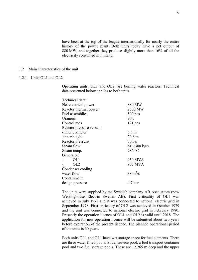
have been at the top of the league internationally for nearly the entire
history of the power plant. Both units today have a net output of
880 MW, and together they produce slightly more than 16% of all the
electricity consumed in Finland
1.2 Main characteristics of the unit
1.2.1 Units OL1 and OL2
Operating units, OL1 and OL2, are boiling water reactors. Technical
data presented below applies to both units.
Technical data:
Net electrical power 880 MW
Reactor thermal power 2500 MW
Fuel assemblies 500 pcs
Uranium 90 t
Control rods 121 pcs
Reactor pressure vessel:
-inner diameter 5.5 m
-inner height 20.6 m
Reactor pressure 70 bar
Steam flow ca. 1300 kg/s
Steam temp. 286 °C
Generator:
- OL1 950 MVA
- OL2 905 MVA
Condenser cooling
water flow 38 m3/s
Containment
design pressure 4.7 bar
The units were supplied by the Swedish company AB Asea Atom (now
Westinghouse Electric Sweden AB). First criticality of OL1 was
achieved in July 1978 and it was connected to national electric grid in
September 1978. First criticality of OL2 was achieved in October 1979
and the unit was connected to national electric grid in February 1980.
Presently the operation licence of OL1 and OL2 is valid until 2018. The
application for new operation licence will be submitted about two years
before expiration of the present licence. The planned operational period
of the units is 60 years.
Both units OL1 and OL1 have wet storage space for fuel elements. There
are three water filled pools: a fuel service pool, a fuel transport container
pool and two fuel storage pools. These are 12.265 m deep and the upper

7
edge is 65 mm above the floor of the reactor hall. They are surrounded
with adequate radiation shields of concrete. The walls and floors of the
pools are covered with stainless steel sheet.
1.2.2 Unit OL3
OL3 unit is under construction. Technical data is presented below.
Thermal power 4 300 MW
Electric output 1 600 MW
Net efficiency approx. 37 %
Reactor pressure 155 bar
Number of fuel assemblies 241
Fuel element:
- matrix 17 x 17
- number of fuel rods 265
- height 4.8 m
- diameter 213.5 mm
- weight 735 kg
Number of control rods 89
Pressure vessel inner height 12.3 m
Pressure vessel inner diameter 4.9 m
Reactor core height (active) 4.2 m
Uranium in reactor 128 t UO2
Containment height 63 m
Containment width 49 m
Containment wall thickness 2.0 m
Design pressure of containment 5.3 bar
Total building volume 950 000 m3
Fuel loading is scheduled to happen by the end of year 2012 and first
criticality and commercial operation are scheduled to be achieved in year
2013. The planned operational period is 60 years.
1.2.3 Interim storage for spent fuel (KPA-store)
Interim storage for spent fuel (KPA-store) locates at plant site and is
used for interim storage of spent fuel from both operating units OL1 and
OL2. Storage capacity for the spent fuel of OL1 and OL2 in the KPA-
store is 1800 tons of uranium. Presently there are three storage pools and
one evacuation pool, which has the capacity to store all spent fuel from
any of the storage pools.

8
KPA-store was taken into use in 1987. Later the planned operational
period of OL1 and OL2 has been increased from 40 years up to 60 years.
Unit OL3 is planned to start its operation in 2012 and KPA-store will be
used for the storage of the spent fuel of OL3, also. Thus, the operational
period of KPA-store is foreseen to continue until 2100's.
The capacity of the KPA-store is presently being increased by three
more storage pools. The extended capacity will be in use in 2013. In the
operating license application of OL3, usage of KPA-store for the
purposes of OL3 will be taken into account in the operating license
application process of OL3.
1.3 Systems for providing or supporting main safety functions
1.3.1 Reactivity control
OL1 and OL2
Reactivity control is provided by the control rods, by the recirculation
pumps, by burnable absorbers in the fuel and by the liquid boron
injection system. Control of reactivity is operationally provided by a
combination of the movable control rods, burnable absorbers and by the
recirculation pump speed. These systems accommodate fuel burn-up,
load changes and long-term reactivity changes.
Rapid insertion of the control rods is performed by the hydraulic scram
system. Fast reduction of recirculation pump speed is also actuated
concurrent with scram ensuring prompt reduction of reactor power.
Normal maneuvering of the control rods is made by means of electric
motors attached to the control rod drives which are operated from the
control rod operating system. Concurrent with insertion of the control
rods with the hydraulic scram system the control rod operating system is
actuated as a back-up. The circuitry for the control rod operating system
is completely independent of the circuitry for the hydraulic scram
system. This separation prevents failures in the control rod operating
system circuitry from affecting the scram circuitry and vice versa.
A standby liquid control system containing neutron absorbing boron
solution constitutes the independent diverse back-up system to the
control rods. The capacity of the boron system, taking a single failure
within this system into account, is such that the reactor can be brought to
a cold shutdown condition at any time during the core life even if no

9
control rod would be inserted and thus all rods remain in their original
positions.
The design of the reactivity control systems assures reliable control of
reactivity under postulated accident conditions with appropriate margin
for stuck rods. The capability to cool the core is maintained under all
postulated accident conditions.
OL3
The plant is provided with two independent reactivity control systems
which work on diverse operating principles: rod cluster control
assemblies (RCCAs) and boron systems (chemical and volume control
system, safety injection systems and emergency boration system). The
RCCAs and emergency boration system are separately capable of
shutting down the reactor during normal operational and anticipated
operational occurrences. Each of the boron systems alone is capable of
maintaining the reactor in a shutdown state at any reactor temperature.
The reactivity control systems are designed to have separate or combined
capabilities, together with the poison added by the emergency core
cooling system, to reliably bring the reactor to and maintain it in the
shutdown condition after postulated accidents.
The reactivity control systems are designed such that the reactor, having
sustained damage in a hypothetical severe accident, or its debris, is
maintained subcritical.
The reactivity control systems together with the protection system are
designed to ensure that no single malfunction of the reactivity control
systems, such as control rod withdrawal at normal speed, results in the
violation of the fuel design limits.
In postulated accidents caused by the failure of the reactivity control
systems (e.g. control rod ejection or drop, or a rapid decrease in the boric
acid concentration in the reactor core), the degree and speed of reactivity
increase is limited in such a way that the design limits for fuel
coolability are not exceeded and that the number of fuel failures possibly
occurring in consequence of the accident is kept to a minimum.
The reactivity control systems are designed to ensure that systems are
capable of accomplishing their safety functions even in the event of a
single failure.
10
1.3.2 Heat transfer from reactor to the ultimate heat sink
1.3.2.1 All existing heat transfer means
OL1 and OL2
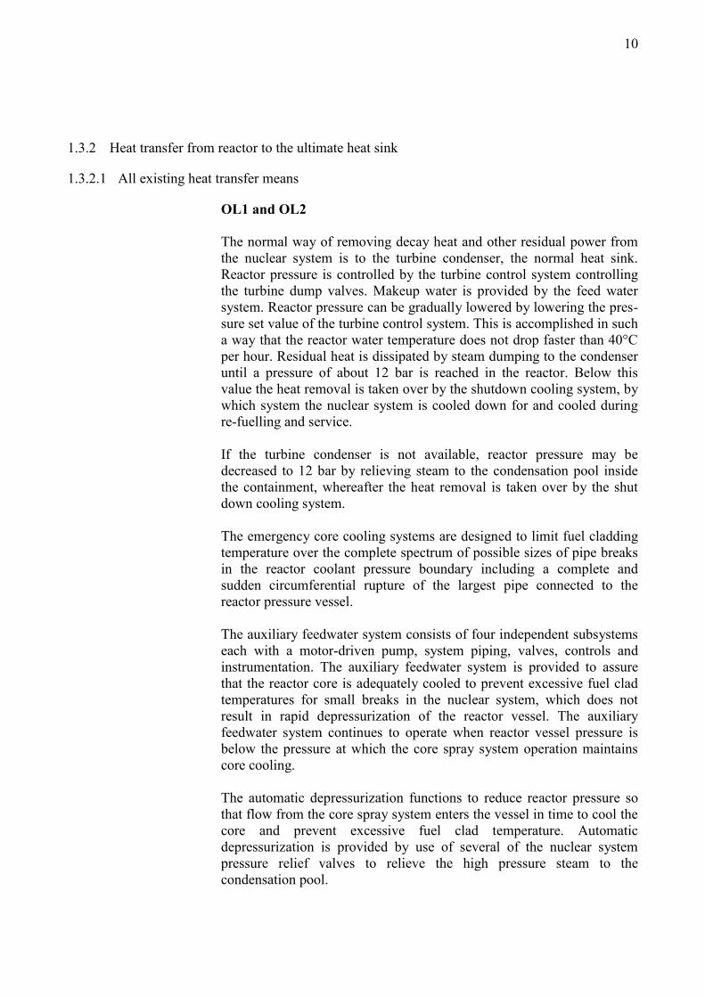
The normal way of removing decay heat and other residual power from
the nuclear system is to the turbine condenser, the normal heat sink.
Reactor pressure is controlled by the turbine control system controlling
the turbine dump valves. Makeup water is provided by the feed water
system. Reactor pressure can be gradually lowered by lowering the pres-
sure set value of the turbine control system. This is accomplished in such
a way that the reactor water temperature does not drop faster than 40°C
per hour. Residual heat is dissipated by steam dumping to the condenser
until a pressure of about 12 bar is reached in the reactor. Below this
value the heat removal is taken over by the shutdown cooling system, by
which system the nuclear system is cooled down for and cooled during
re-fuelling and service.
If the turbine condenser is not available, reactor pressure may be
decreased to 12 bar by relieving steam to the condensation pool inside
the containment, whereafter the heat removal is taken over by the shut
down cooling system.
The emergency core cooling systems are designed to limit fuel cladding
temperature over the complete spectrum of possible sizes of pipe breaks
in the reactor coolant pressure boundary including a complete and
sudden circumferential rupture of the largest pipe connected to the
reactor pressure vessel.
The auxiliary feedwater system consists of four independent subsystems
each with a motor-driven pump, system piping, valves, controls and
instrumentation. The auxiliary feedwater system is provided to assure
that the reactor core is adequately cooled to prevent excessive fuel clad
temperatures for small breaks in the nuclear system, which does not
result in rapid depressurization of the reactor vessel. The auxiliary
feedwater system continues to operate when reactor vessel pressure is
below the pressure at which the core spray system operation maintains
core cooling.
The automatic depressurization functions to reduce reactor pressure so
that flow from the core spray system enters the vessel in time to cool the
core and prevent excessive fuel clad temperature. Automatic
depressurization is provided by use of several of the nuclear system
pressure relief valves to relieve the high pressure steam to the
condensation pool.
11
The core spray system consists of four separate, independent subsystems
each with a motor-driven pump, system piping, valves and associated
controls and instrumentation. At low pressure the system feeds water
into the reactor vessel in time and at a sufficient flow rate to cool the
core and prevent excessive fuel temperature.
In the analysis of emergency core cooling systems' performance it is
assumed that the function is degraded by a single failure and
maintenance (N+2-criterion) and it is shown that the safety objective is
still achieved.
In case the normal and emergency cooling system would be unavailable,
there exists a possibility to use atmosphere as the ultimate heat sink. This
would be done by using containment filtered venting for relieving steam
to the atmosphere.
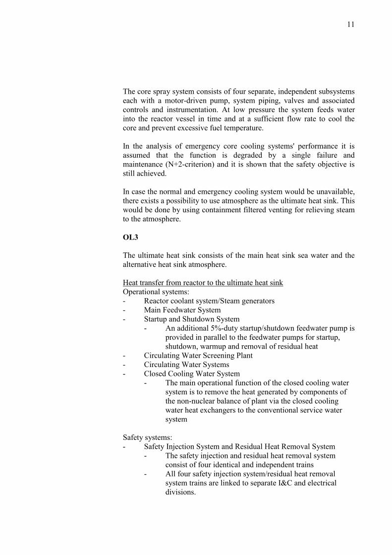
OL3
The ultimate heat sink consists of the main heat sink sea water and the
alternative heat sink atmosphere.
Heat transfer from reactor to the ultimate heat sink
Operational systems:
- Reactor coolant system/Steam generators
- Main Feedwater System
- Startup and Shutdown System
- An additional 5%-duty startup/shutdown feedwater pump is
provided in parallel to the feedwater pumps for startup,
shutdown, warmup and removal of residual heat
- Circulating Water Screening Plant
- Circulating Water Systems
- Closed Cooling Water System
- The main operational function of the closed cooling water
system is to remove the heat generated by components of
the non-nuclear balance of plant via the closed cooling
water heat exchangers to the conventional service water
system
Safety systems:
- Safety Injection System and Residual Heat Removal System
- The safety injection and residual heat removal system
consist of four identical and independent trains
- All four safety injection system/residual heat removal
system trains are linked to separate I&C and electrical
divisions.

12
- In-containment Refueling Water Storage Tank is common
to the four safety injection system trains
- Emergency feedwater system
- Only function is to supply the required water to the steam
generators secondary side
- The emergency feedwater system consists of four
redundant trains
- Component Cooling Water System
- The function of the component cooling water system is to
transfer heat from safety and operational process systems to
the main heat sink
- Component Cooling Water System consists of four
separate trains
- The system also includes two trains of the dedicated
cooling chain for conditions associated with the mitigation
of postulated severe accidents
- Essential Service Water System
- The function of the essential service water system is to
provide cooling of the component cooling water system
heat exchangers with water from the ultimate heat sink
- The essential service water system comprises four trains,
each serving one train of the component cooling water
system
Heat transfer from spent fuel pools to the ultimate heat sink
- Fuel Pool Cooling and Purification System
- System consists of two separate trains
Heat transfer from the reactor containment to the ultimate heat sink
- Containment Cooling Ventilation System
- The containment cooling ventilation system has no safety
functions except to cool and maintain ambient conditions
of the reactor pit during loss of offsite power and station
blackout
- Containment Heat Removal System
- The containment heat removal system provides cooling of
the in-containment refueling water storage tank and of the
spreading area in case of hypothetical core melt accidents.
- 2x100%-duty system, i.e. one train is sufficient to fulfill the
safety function
- Containment Filtered Venting System
- The Containment Filtered Venting System can be used to
release the non-condensable gases and the remaining steam
fraction in a later stage of the accident in order to
depressurize the containment and terminate the possible
release of radioactive substances into the environment.

13
- Pressure relief by the filtered vent gas release to the
environment provides effective retention of airborne
aerosols and iodine.
1.3.2.2 Lay out information on the heat transfer chains
Routing of redundant and diverse heat transfer piping and location of the
main equipment as well as physical protection of equipment against
internal and external threats is explained in Appendix 1 for OL1, Ol2
and KPA-store, and, in Appendix 2 for OL3.
1.3.2.3 Possible time constraints for availability of different heat transfer chains, and possibilities
to extend the respective times by external measures
OL1 and OL2
If all the connections to the off-site power grids are lost, the emergency
diesel generators are started automatically within 10 seconds and the
Olkiluoto gas turbine plant, which serves as an alternative onsite back-up
AC source, can typically be started and connected in about 10 minutes.
Availability of the above mentioned back-up power sources is sufficient
to provide cooling of the reactor core.
In case the condensation pool is used as the heat sink and the pool
cooling has been lost, release of steam from the containment becomes
necessary after about 8 hours.
The tanks of the de-mineralized water distribution system contain a
minimum amount of water of 900 tons, which is enough for core cooling
purposes for about 1.5 days after reactor trip. If off-site power is
available, an adequate amount of de-mineralized water can be produced
for cooling both OL1 and OL2. It is also possible to replenish the water
inventory with the help of the fire fighting water system using temporary
arrangements.

14
OL3
The power supply to the core cooling systems is provided by following
means: one of two connections to the off-site 400 kV and 110 kV grids,
house turbine operation, emergency diesel generators and the gas
turbine. Thanks to the large amount of water in the steam generators,
cooling of the core can be assured for 2 hours without any AC power. In
addition there are two station black out diesels available. They can be
started and connected manually and they provide the required power for
core cooling.
According to the plant design basis the water content of the emergency
feedwater system tanks is sufficient for feeding the steam generators for
24 hours and there is a permanent water reservoir at the site for
additional 48 hours.
1.3.2.4 AC power sources and batteries that could provide the necessary power to each chain (e.g.,
for driving of pumps and valves, for controlling the systems operation)
OL1 and OL2
The available primary power sources have been described in section
1.3.2.3. above. The in-house power system is divided into four
subsystems. Each of them includes necessary batteries which provide the
required DC power for the corresponding control functions of the safety
functions.
OL3
The available primary power sources have been described in section
1.3.2.3. above. The in-house power system is divided into four
subsystems. Each of them includes necessary batteries which provide the
required DC power for the corresponding control functions of the safety
functions.
1.3.2.5 Need and method of cooling equipment that belong to a certain heat transfer chain
OL1 and OL2
The normal and preferred heat transfer chain consists of the main
condenser and the condensate and feedwater systems. Normally, the
condenser is available when the reactor pressure is above 12 bar. The
pumps of the condensate and feedwater systems as well as the main
condenser are dependent on sea water.

15
The pumps of shut-down cooling system need active cooling.
The locations of the pumps of containment vessel spray system, core
spray system and auxiliary feed water system are cooled by air coolers
which are dependent on sea water cooling. However, if these air coolers
are not operable, the pump locations can also be cooled by opening the
doors and flaps at the grade level and at the ceiling, thus utilizing the
chimney effect.
The recirculation lines in auxiliary feed water system also need active
cooling in order to avoid overheating. Modifications are being planned
in auxiliary feed water system in order to make it independent from the
main heat sink.
OL3
Systems which are used for cooling equipment that belong to a certain
heat transfer chains are:
- Safety Chilled Water System
- Operational Chilled Water Systems
- Safeguard Building Controlled-Area Ventilation System
- Nuclear Auxiliary and Fuel Building Ventilation System
- Radioactive Waste Building Ventilation System
- Main Control Room Air Conditioning System
- Electrical Division of the Safeguard Building Ventilation System
- Diesel Building Ventilation Systems
- Main Steam and Feedwater Valve Compartment Ventilation
System
- Ventilation System for Operational Chilled Water System,
Switchgear Area of Nuclear Auxiliary Building Ventilation
System
- Service Water Pump Building Ventilation System
Details, including their function, protection against internal and external
hazards, installation and electrical power supply are given in Appendix
2.

16
1.3.3 Heat transfer from spent fuel pools to the ultimate heat sink
OL1 and OL2
The pool water system is used for fuel pool cooling under normal
operation. Water is circulated using a pump from the level adjustment
tank to the pools, and back into the level adjustment tank by means of
overflow via the pool gutters. Water in the pools is cooled by using the
two heat exchangers in the system. The heat exchangers are cooled using
either shut-down secondary cooling system or diesel-backed normal
operation secondary cooling system.
If it is assumed that all systems used for pool cooling and the auxiliary
water system are lost, fire fighting water may be sprayed into the fuel
pools by using hoses. In case of prolonged fault in the cooling the water
in the pools would heat up and eventually start boiling. Boiling will
remove heat from the fuel pools and make-up water is received from fire
fighting water line.
The two fuel pools are located in the reactor building.
Further information on the location of pumps and heat exchangers of the
pool water system, diesel-backed normal operation service water system,
diesel-backed normal operation secondary cooling system, and, fire
fighting water system is given in Appendix 1.
KPA-store
The fuel pool cooling systems has two separate trains transferring heat
into the ultimate heat sink through diesel-backed normal operation
service water system. One train is capable of for the required cooling
function and in case of malfunction of the primary train the secondary
train would be used.
Layout information on the heat removal systems in KPA-store are given
in Appendix 1.
The spent fuel stored in KPA-store is relatively old and, thus, the decay
heat production is low. The time delays for warming up, boiling and
water level decreasing in case of loss of decay heat removal systems are
several weeks.
If assuming the loss of ultimate heat sink and loss of power in the KPA
store the fire fighting water can be used for supplying additional water to
the KPA storage pools.

17
OL3
The fuel pool cooling system removes the decay heat from the spent fuel
pool during normal plant operation (power operation and outages) and
during accidents. Fuel pool purification system participates in heat
removal by the safety injection system and residual heat removal system
during LOCA.
In case of loss of offsite power both trains of fuel pool cooling system
remain operable as they are supplied by the emergency diesel generator.
Also cooling water is available as the four pumps of the operational
component cooling water system are emergency power supplied.
If it is assumed that all systems used for pool cooling and the auxiliary
water system are lost, fire fighting water may be sprayed into the fuel
pools by using hoses. In case of prolonged fault in the cooling the water
in the pools would heat up and eventually start boiling. Boiling will
remove heat from the fuel pools and make-up water is received from fire
fighting water line.
1.3.4 Heat transfer from the reactor containment to the ultimate heat sink
OL1 and OL2
During normal operation, the drywell of the containment vessel is cooled
by means of radiators, by blowing the gas inside the drywell (nitrogen-
filled containment) through the radiators. The radiators are cooled by
using water from the diesel-backed secondary cooling system from
where heat is transferred into the sea.
The condensation pool inside the containment is cooled by means of the
containment vessel spray system. During disturbances where steam
enters the containment drywell or the wetwell gas space, steam may be
condensed by spraying water from the condensation pool into the above
spaces. Water condensed from steam flows into the condensation pool.
The heat is transferred into the sea.
Adding and removing water to and from the condensation pool is carried
out by means of the containment vessel spray system and the liquid
waste system.
Information on lay out, physical protection, time constraints of use,
power sources, and cooling of equipment is given in Appendix 1.

18
OL3
The containment cooling ventilation system is used to maintain the
ambient conditions to ensure the proper operation of the reactor coolant
system components, control rod drive mechanisms and correct
functioning of instrumentation and control equipment. It also prepares
acceptable ambient conditions for the personnel working in the reactor
building containment equipment compartments during outages and
maintains acceptable ambient conditions for the personnel working
inside the reactor building service compartments and maintains the
ambient conditions needed to ensure the correct functioning of
instrumentation and control equipment.
The containment heat removal system provides cooling of the in-
containment refuelling water storage tank.
If all the other residual heat removal systems are lost, the containment
filtered venting system can be used to release steam from the
containment and terminate the pressure increase.
Information on lay out, physical protection, time constraints of use,
power sources, and cooling of equipment is given in Appendix 2.
1.3.5 AC power supply
1.3.5.1 Off-site power supply
1.3.5.1.1 Information on reliability of off-site power supply: historical data at least from power
cuts and their durations during the plant lifetime.
There are two offsite grids available for Olkiluoto NPP units, 400 kV
grid and 110 kV grid. They are described more detailed in the next
chapter. The primary means of power needed in onsite electric power
system is supplied from offsite 400 kV grid.
The reliability data of the 400 kV grid and switchyards in Olkiluoto has
been given by the national grid operator Fingrid. Data is recorded since
year 1980 and is presented below from the time period of 1980-2011:
- OL1: 5 power cuts, cut time altogether 295 minutes
- OL2: 2 power cuts, cut time altogether 172 minutes
Power cuts consist of the situations where connection to the 400 kV
switchyard and by this means to grid has been lost and power couldn't be
supplied to or from the grid. Reasons for these have been the human
mistakes made while connecting and protection relay faults. In all cases

19
the 400 kV grid itself would have been available but connection to it was
lost.
1.3.5.1.2 Connections of the plant with external power grids: transmission line and potential earth
cable routings with their connection points, physical protection, and design against
internal and external hazards.
The electricity produced in the NPP unit is supplied to offsite 400 kV
grid. When the NPP unit is not operating, the power needed in onsite
electric power system is supplied from offsite 400 kV grid through two
auxiliary normal transformers. If the offsite 400 kV grid or the main
transformer is not available, the power needed in onsite electric power
system is supplied from offsite 110 kV grid through the auxiliary
standby transformer. The electricity produced in the NPP unit cannot be
supplied to offsite 110 kV grid.
The electricity produced is supplied through the overhead lines to the
nearest 400 kV switchyard which is located in Olkiluoto island few
kilometers from the plant units. The 110 kV switchyard is located beside
the existing OL1 and OL2 plant units, approx. 1 km from OL3. Power
there is coming from the 110 kV grid through the overhead lines and
connections from the switchyard to the plant units are made with
underground cables.
Connection to the offsite grids is agreed through the Connection
Agreement, signed between TVO and national grid operator Fingrid.
For ensuring the power system security, all the power plants including
NPP units OL1, OL2 and OL3 must withstand the variations in voltage
and frequency caused by the power system, remain synchronised and
behave as planned in case disturbances occur in the network. Due to this,
power plants must fulfill the requirements "Specifications for
Operational Performance of Power Plants" when they are connected to
the grid. The specifications follow in applicable parts the Nordel
specification "Operational Performance Specifications for Thermal
power Units larger than 100 MW". The requirements specify for
example the generator and voltage regulator characteristics, tolerance for
frequency and voltage variations and requirements concerning the power
control characteristics.
20
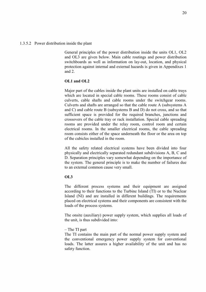
1.3.5.2 Power distribution inside the plant
General principles of the power distribution inside the units OL1, OL2
and OL3 are given below. Main cable routings and power distribution
switchboards as well as information on lay-out, location, and physical
protection against internal and external hazards is given in Appendixes 1
and 2.
OL1 and OL2
Major part of the cables inside the plant units are installed on cable trays
which are located in special cable rooms. These rooms consist of cable
culverts, cable shafts and cable rooms under the switchgear rooms.
Culverts and shafts are arranged so that the cable route A (subsystems A
and C) and cable route B (subsystems B and D) do not cross, and so that
sufficient space is provided for the required branches, junctions and
crossovers of the cable tray or rack installation. Special cable spreading
rooms are provided under the relay room, control room and certain
electrical rooms. In the smaller electrical rooms, the cable spreading
room consists either of the space underneath the floor or the area on top
of the cubicles installed in the room.
All the safety related electrical systems have been divided into four
physically and electrically separated redundant subdivisions A, B, C and
D. Separation principles vary somewhat depending on the importance of
the system. The general principle is to make the number of failures due
to an external common cause very small.
OL3
The different process systems and their equipment are assigned
according to their functions to the Turbine Island (TI) or to the Nuclear
Island (NI) and are installed in different buildings. The requirements
placed on electrical systems and their components are consistent with the
loads of the process systems.
The onsite (auxiliary) power supply system, which supplies all loads of
the unit, is thus subdivided into:
– The TI part
The TI contains the main part of the normal power supply system and
the conventional emergency power supply system for conventional
loads. The latter assures a higher availability of the unit and has no
safety function.
21
– The NI part
The NI contains a small part of the normal power supply system and the
emergency power supply system. The emergency power supply system
is designed to supply all safety-related loads. The normal power supply
system shall supply the non-safety-related loads in the NI area.
The guidelines require separate sections for
– AC Power Systems and
– DC Power Systems
meaning interruptible (AC) and uninterruptible (DC) Power Systems.
The AC power system comprises the interruptible AC power system of
the
– normal power supply system (NPSS), and
– emergency power supply system (EPSS).
The DC power system comprises
– in case of TI the uninterruptible DC and AC power systems, and
– in case of NI the uninterruptible AC and DC power systems of the
EPSS.
1.3.5.3 Main ordinary on-site source for back-up power supply
OL1 and OL2
The plant units OL1 and OL2 have several different options for
electricity supply. When the plant is running, the plant unit's main
generator supplies the internal consumption loads via the house load
transformers. If the connection to the external grid is lost while the plant
unit is running, the unit tries to switch to house load operation. In this
case, the plant unit's own main generator remains in operation, only
supplying the internal consumption loads. If the plant unit's own
electricity generation is interrupted, the internal consumption loads are
supplied by the external 400 kV network via the main transformer and
the house load transformers. If the connection to the 400 kV network has
been lost, and transfer to house load operation is unsuccessful, electricity
supply is automatically switched to the external 110 kV network via the
start-up transformers.
If both the house load option and both external networks have been lost,
the plant unit has four back-up diesels, one for each subsystem. These
automatically start and supply the systems required to bring the plant
unit to a safe state.

22
The diesel generator units are located in different rooms according to
separation principle.
Each diesel generator has a fuel tank, sufficient for eight hours of
operation at full nominal power. Each of the plant units have their own
storage tank, which is enough to supply all four diesel generators
simultaneously at full nominal power for one week. The running fuel
tanks are automatically filled from the storage tank. Additional fuel is
brought into the storage tanks by means of tanker lorries.
OL3
The emergency power supply is designed to ensure that the safety
systems are powered in the event of loss of the preferred electrical
sources.
It is designed as four separate and redundant trains arranged in
accordance with the four division concept. Each train is provided with an
emergency diesel generator (EDG) set.
The safety loads connected to the emergency power supply correspond
to those required to safely shut down the reactor, remove the residual
and stored heat and prevent the release of radioactive substances.
In the event of total loss of the four EDGs (i.e. station blackout or SBO),
two additional generators, the SBO emergency diesel generators, provide
the necessary power to the emergency loads. They are connected to the
safety busbars of two divisions.
One EDG diesel or one SBO diesel is sufficient to keep the plant in a
controlled state, i.e. hot shutdown state. Reducing the loads the fuel is
sufficient for at least three weeks to keep the plant in controlled state.
1.3.5.4 Diverse permanently installed on-site sources for back-up power supply
Fingrid Oyj has constructed a gas turbine power plant of approx. 100
MW net output at Olkiluoto in Eurajoki. The gas turbine power plant
consists of two gas turbine machine units of approx. 50 MW. Both gas
turbine machine units consist of two gas turbines and one generator.
Fingrid uses the plant as part of what is known as the national grid's
rapid disturbance reserve. TVO has participated in the costs of the
project with a share of 50%, and the gas turbine power plant is available
for TVO to secure the internal consumption power supply of the
Olkiluoto nuclear power plant units during external network connection
disturbances.

23
The plant is independent from other systems and for black start
situations it has dedicated diesel generators. The plant is designed with
starting possibilities locally, from Olkiluoto 1, Olkiluoto 2, Olkiluoto 3
or the Fingrid's central control rooms. Connection of gas turbine supply
is manual only.
The gas turbine power plant is located on the island of Olkiluoto, in the
immediate vicinity of the power plant units. In addition to the 110 kV
switchgear plant connection, supplies to the plant units have also been
set up as 6.6 kV medium-voltage cable connections. The cables are
installed in the ground inside cable ducts.
There are two fuel storage tanks for the operation of the gas turbine
power plant. At a power level of approx. 20 MW, which is enough to
maintain OL1, OL2 and OL3 at a safe state simultaneously, the stored
amount of fuel is sufficient for one week of operation. Additional fuel is
brought into the storage tanks by means of tanker lorries.
1.3.5.5 Other power sources that are planned and kept in preparedness for use as last resort means
to prevent a serious accident damaging reactor or spent fuel
Opportunities for cross-connection between the plant units
Unit to unit interconnections will be provided via the Olkiluoto 400 kV
offsite switchyard. Between OL1 and OL2 the direct diesel busbar
connections are also provided. Unit to unit connections can provide
power for the safety systems of other nuclear unit on Olkiluoto and vice
versa during house load operation. Best estimation for the connection time
is under 1 hour.
Once the OL3 plant unit is completed, it may be used for supplying
electricity between plant units.
Reserve start-up electricity
Reserve start-up electricity means a direct 110 kV connection to a
nearby hydro power station. It is created by Fingrid after an order from
OL1 or OL2 main control room to secure the internal consumption
electricity once the external 400 kV and 110 kV grids have been lost,
transfer to house load operation has failed, and the gas turbine plant is
not available.
24
Electricity supply from the outside area, using Paneliankosken Voima
Oy's 20 kV network
Reserve electricity may also be connected to the OL1 and OL2 plant
units via the electricity supplies of the outside areas. In this case,
electricity is supplied from local medium voltage distribution network.
Transportable equipment at the site
The plant units OL1 and OL2 have two transportable diesel generators.
Portable electric power sources are not designed for the OL3.
Technical details on the alternative fixed and transportable power
sources are given in Appendices 1 and 2.
1.3.6 Batteries for DC power supply
OL1 and OL2
Batteries are used in two safety-related UPS-backed alternating current
systems, and in five battery-backed direct current systems, of which
three are safety-related and two non-safety related.
During normal conditions, the permanent charge of the batteries is
maintained either by the UPS's rectifier, or the rectifier for direct current
systems.
Technical information on consumers served by each battery bank:
driving of valve motors, control systems, measuring devices, etc. as well
as information on location and separation is given in Appendix 1.
In a longer-standing fault scenario, the fixed rectifiers of direct current
systems may be replaced by transportable rectifiers on wheels. There are
transportable rectifiers for all DC voltage levels, and both plant units
have their own. The transportable rectifiers are technically similar to the
fixed ones.
OL3
The Uninterruptible Power Supply (UPS) has the task of supplying
power continuously to loads which must operate without interruption
even when there is a loss of power from the normal power source (e.g.
during diesel start-up's).
Several diverse power supplies related to the UPS equipment and I&C
power supply prevent a common cause failures (CCF) in the

25
uninterruptible power supply system. These power supplies are
described in detail in Appendix 2.
Improving reserve power generation
TVO has started analyses to improve reserve power generation at
Olkiluoto. In practice, this would mean increasing the number of mobile
generators or other reserve power equipment.
The need for additional power concerns all power plant units
(OL1/OL2/OL3), as well as some other buildings at Olkiluoto and
certain electricity consumers in the outside areas. Analysis of the
additional charging opportunities for batteries is included in this work.
1.4 Significant differences between units
Considering safety systems units OL1 and OL2 are identical. OL3 has a
design of it's own.
1.5 Scope and main results of Probabilistic Safety Assessments
OL1 and OL2
The PSA for OL1 and OL2 is a full scope analysis including power
operation, annual outages as well as planned shutdown and start-up of
the plant. Internal initiating events, internal and external hazards and
harsh weather conditions are included. Due to the similarity of the plants,
level 1 PSA modelling is common to OL1 and OL2.
The total core damage frequency according to the up-to-date level 1
PRA model is 1.3E-5 per year per plant (i.e. per reactor year). Most of
the core damage risk contribution, about 80%, comes from the power
operation. Planned shut-downs and start-ups have almost equal risk
contribution, about 8% each, whereas only about 4% of the annual core
damage frequency comes from the refuelling outage.
The relative contribution of the initiating events categories to core
damage frequency resulting from power states is presented in Figure 1.5-
1 below.

26
Transients31 %
Seismic1 %
Weather20 %
LOCAs10 %
Fires18 %
Outage2 % Flooding
1 % Missiles0 %
Planned shutdown to hot shutdown
6 %
Shutdown from hot to cold shutdown
2 %
Start-up8 %
Total CDF
Figure 1.5-1. The contribution to the total core damage frequency (1.3E-
5 1/year) classified according to the origin of the initiating events.
The result of level 2 PSA gives the probability for a large release (100
TBq cesium-137 equivalent) as a consequence of core damage. The
combined mean frequency of large release accident progression bins is
3.5E-6 1/reactor year.
OL3
The core damage frequency resulting from initiating events during
power states is calculated with 1.37E-06/a (point estimate). Relative
contribution of initiating event categories leading to core damage
resulting from power states is presented in Figure 1.5-2.

27
Figure 1.5-2. The contributions of initiating event categories show the
Internal Hazards with 47% (leadingby IH Fire – 44%) as major
contributor to CDF during power states followed by Loss of offsite
power with 9.5% (dominated by short LOOP < 2h). and External
Hazards with 8.8% (dominated by Loss of ultimate heat sink due to Oil
Spills, EH W12). ATWS category, with contribution of 9% to CDF,
includes all initiators with failed reactor trip (dominated by ATWS after
IH F_A - Internal Hazard Fire leading to transients).
The level 2 PSA result for exceeding of 100 TBq cesium-137 equivalent
release is 5.6E-8 /yr.
2 Earthquakes
2.1 Design basis
OL1 and OL2
Earthquake was not part of the original design basis of units OL1 and
OL2. Since then plant modifications to fulfil regulatory demand for
PGA-value of 0.1 g have been done.
Earthquakes have been analysed in OL1/OL2-PSA chapter 17
(Probabilistic earthquake analysis). The analysis includes the estimation
of seismic hazard in Olkiluoto, list of components and equipment,
earthquake response of buildings and equipment, plant walk downs,
containment analysis and probabilistic model based on the presented
data.

28
In plant modifications the seismic design requirement are set according
to the seismic ground response spectrum as specified in guide YVL 2.6
for southern Finland and it is modified to correspond the PGA level
0.1 g.
KPA-store
The PGA-value of 0.1g has been applied in design of KPA pools.
The PGA-value of 0.1g has been applied in design of KPA pools. Static
method has been used in the original, first phase, pool design. Currently
for the modification for extended capacity of KPA-storage, the seismic
design for both pool structures and storage building structures has been
done using dynamic analyses according to YVL 2.6.
OL3
All seismic classified buildings are designed according to the design
earthquake load. The design basis for loads for earthquake is based on
YVL 2.6 requirements, because the calculated PGA level in Olkiluoto
site is lower than the minimum value required in the guide YVL 2.6.
Definition of Loads from the viewpoint of safety design and dynamic
analysis, the design basis earthquake is the only earthquake to be
considered.
The seismic loads for the design basis earthquake are defined as follows:
- The same profile is used for the horizontal and vertical directions.
- Zero period acceleration
- Horizontal: 0.1 g
- Vertical: 2/3 of the horizontal
- The ground response spectrum is given for 5% damping. This
spectrum is in accordance with YVL Guide 2.6.
The input motion is defined at the finished grade in the free field, in
three orthogonal directions described by response spectra corresponding
to statistically independent time histories. The two horizontal
components are described by equal response spectra.
The probabilistic seismic PSA analysis is documented as chapter 6.1 of
OL3 PSA documentation.
The probabilistic seismic hazard assessment at Olkiluoto has been
estimated in connection to the seismic PSA of the Olkiluoto plant units
and it consists of three parts: 1) source effects, 2) path effects, 3) site
effects. Because there are no registered strong motion acceleration
recordings of earthquakes in Finland, the earthquake recordings from
29
Saguenay and Newcastle regions from Canada and Australia were taken
as sources of initial data because of their geological and tectonical
similarity to Fennoscandia.
The hazard curve shows the return period (annual frequency of
exceeding) as a function of peak acceleration level. The probability of
seismic activity exceeding the PGA amplitude level of 0.1 g is very low.
The ground response spectra for OL3 with uncertainty bounds are
presented as defined in the probabilistic seismic hazard assessment.
At the 1·10-5
annual frequency level (100000 year return period), the
median peak ground acceleration level (PGA) is 0.085g for Olkiluoto
site. Because the calculated PGA level is lower than the minimum value
required in the guide YVL 2.6, the PGA value of 0.1g is set for the
design basis earthquake.
Design basis for the nuclear installations at Olkiluoto site are met.
Consequential flooding due to earthquake flooding exceeding the design
basis flood is not relevant for the Olkiluoto site.
2.2 Evaluation of safety margins
OL1 and OL2
Based on Seismic PRA the core damage risk due to earthquakes is
estimated as 1,7e-7 1/year. The median capacity of the OL1/OL2 plant is
about 0.35g. The HCLPF (95% confidence of a less than 5% probability
of failure) of the plant can be estimated to be about 0.12g.
The anchoring improvement of some relay cabinets to prevent relay
chatter is the most important modification that is foreseen to reduce core
damage risk. Modification proposal has been done and work is ongoing
OL3
The lowest HCLPF capacities lay in the range of 0.2g. Thus sufficient
seismic margins well beyond the EUR requirements (40% beyond the
horizontal PGA of the DBE, i.e. HCLPF>0.14g) are demonstrated.

30
3 Flooding
3.1 Design basis
OL1 and OL2
According to design basis a rise of sea water to the level of N60+3.5 m
may not endanger safe shutdown of the plant nor the environmental
radiation safety. In order to fulfil this demand following design assets are
fulfilled:
- Reactor building is watertight and can withstand external water
level to the level of N60+3.5 m.
- Integrity of other safety significant structures is secured either by
structural robustness or flood gates.
- Systems needed to safe shut down may not be endangered of a
flood reaching N60+3.5 m. In practise e.g. the so called H-bays,
in which many pumps of the safety systems are located, are water
tight are least to level N60+3.5 m. Also, the waste handling
systems have been designed to be water tight or they are located
above the level N60+3.5 m.
The designation N60 refers to the average sea water level in the year
1960. Due to the land elevation the effective grade level is today about
30 cm higher.
KPA-store
For the KPA storage, structural design has been performed assuming a
seawater level +1.2 m. However, the intrusion of ground water or sea
water into the building does not threaten the pool structures.
OL3
Safety aim is to ensure global stability of the building structures, and no
water ingress into the buildings.
Subjects considered in layout and design are increased buoyancy loads
and hydrostatic pressure loads on outer structures including penetrations
Possible water ingress via “open” piping system is avoided.
The buoyancy loads and hydrostatic pressure loads on the outer
structures including penetrations are considered for the building design
for a seawater level of N60+3.50 m.
31
The relevant penetrations below building level +0.00 m are tightened
and building joints are tightened by Omega Water Stops. The Omega
Water Stops are designed for a water height of 4 m or 25 m depending
on the location. They prevent flooding from one division to another.
Internal and external flooding routes and consequences of flooding are
analyzed within FSAR topical report on flooding analysis. It is assured
that flooding up to N60+3.5 m does not endanger the systems, structures
or components required to maintain critical safety functions.
The general boundary conditions are as follows:
It is assumed that a water level of N60 +3.5m (equivalent to building
level + 0.00m) is given on the plant site, i.e. also around the buildings. A
water ingress into the buildings via doors or other penetrations on level
+0.00m has not been analyzed. Reasoning: Margin of 30 cm between
site level (N60 +3.2m) and building level + 0.00m is already included.
3.2 Evaluation of safety margins
OL1 and OL2
According to the statistical assessments of the Finnish Meteorological
Institute, the sea level exceeding +3.5 m is at Olkiluoto area so
improbable that it is not necessary to take actions. Information about the
fluctuations of the sea level is updated, among others, in the research
projects in the SAFIR program.
Consequences of assumption that the sea water level exceeds N60 + 3.5
m have been described in Appendix 1.
The event that the design basis flood would be exceeded is so
improbable that any measures to increase robustness of the plant against
flooding are not necessary. However, in connection with future plant
modifications, the robustness of the plant against flooding can be
improved, too.
KPA-store
To ensure the cooling of the KPA storage fuel pools analyses on diverse
the residual heat removal of the KPA storage are being started.
A probabilistic risk analysis (PRA) will be prepared for the KPA storage
during its expansion. The risk analysis will contain the risks of internal
and external initiating events. In the analysis, the risk caused by flooding
will also be studied. Any modifications improving nuclear safety will be

32
analysed based on the results of the probabilistic risk analysis for the
KPA storage.
OL3
The outside doors have not water tightness requirements. Nuclear Island
outer door tests have been performed: doors are leak tight at the level
N60+15.5m (12 m above threshold of the door, the leak less than 10 l/h).
However, the probability of reaching the water level N60+3.5 m is very
low.
4 Extreme weather conditions
4.1 Design basis
OL1 and OL2
Design basis considering extreme weather conditions is shown in the
present OL1/OL2-FSAR chapter 4. These are supported by OL1/OL2-
PSA-analysis, where weather conditions have been analysed in chapter
16 ("weather -PSA"). About 40 phenomena have been screened and the
adequacy of the design basis has been ensured. Following phenomena
have been screened for further study and the results will be discussed in
the final report. Earlier the results have been described in chapter 1 in
reference 2.
- Outside air temperature and humidity
- Seawater temperature
- Precipitation
- Wind
- Phenomena, which could endanger the intake of seawater
- External flooding and high seawater level
- Lightning
- External fire (terrain-, bush-, forest fire)
- Snow and ice
Design basis for each weather phenomenon is presented in Appendix 1.
OL3
The design values of weather conditions are presented in FSAR and the
assessments of the weather conditions' frequencies are done in PSA.
After 2007 the extreme weather conditions, weather phenomena and the
33
area specific weather data have been researched in the research project
SAFIR/EXWE
Design basis for the following weather phenomenon is presented in
Appendix 2:
- Maximum Air Design Temperatures
- Minimum Air Design Temperatures
- Maximum External Humidity Conditions
- Wind speed
- Strong Winds speed return periods
- Tornado return periods
- Cooling water temperature
- Seawater level
- Low sea water level
- Rainfall
- Snowfall
- Lightning
- Hazards with potential effects on plant items such as cooling
water intakes, air intakes
- Site proximity hazards
Evaluation of each hazard including results from multiple events -
screening analysis are presented in Appendix 2.
4.2 Evaluation of safety margins
OL1 and OL2
Outside air temperature and humidity
A risk for nuclear safety due to very high or very low air temperature is
remarkably small. As results of a recent study on low temperatures and
loss of room heating small plant changes have been done. These includes
alarms on low temperature in some rooms and manually operated
ventilation gate valves.
Seawater temperature
When seawater temperature exceeds 27°C, the operation mode of the
plant unit is decided on separately, and the decision is processed by the
Local Safety Committee. The safe state in each operation mode is
evaluated on a case by case basis. Based on experience, the high
temperature peaks have been short, and a change in wind direction, for
example, may quickly lower seawater temperature.
Appearance of frazil ice is a characteristic phenomenon to the site. To
prevent operational disturbances due to frazil ice, pumps that allow

34
water to be pumped from the discharge side to the inlet side have been
installed. The rate of this recirculation flow is 1 m3/s at both plant units.
The recirculation pumping is started as a precaution, when the
temperature of the incoming seawater falls below +2°C.
Precipitation
Amount of heavy precipitation, which could cause pool formation in the
vicinity of reactor building, has been re-estimated in 2010. Corrective
actions to enhance storm draining at outside areas of OL1 and OL2 are
in progress and to be completed in 2012.
Wind
Design basis of the buildings for the wind speed is 50 m/s that
corresponds to the Finnish civil construction standards. The probability
of exceeding the design basis is very low.
Phenomena, which could endanger the intake of seawater
The result of seawater channel blocking, either intake or output, could
eventually lead into seawater flow to the outside areas of the auxiliary
building. The enhancements of surface draining, which are being done to
avoid pool formation by heavy precipitation, will also lead the excess
seawater away from reactor building.
External flooding and high seawater level
This issue has been discussed in chapter 3.
Lightning
During the plant unit modernisation in 1996, a separate lightning strike
risk evaluation was performed. The current preparations are sufficient.
External fire (terrain-, bush-, forest fire)
Wildfires, bushfires and forest fires don't pose any danger to the plant
beside the possible loss of the external grid. There are considerable
safety margins for the loss of the external grid.
Snow and ice
Large snow loads may be prepared for in time by removing the snow.
Combustion air for the diesel generators is usually taken from the
outside. If the grille on the air duct should be blocked due to snow, an
alarm for the pressure difference across the grille would first be received
in the control room. If the pressure difference were to increase further,
the air intake of the diesel in the room would automatically be switched
to the inside.
35
Snow pile up due to wind occurs against one plant unit wall at a time. As
the diesel generators are located so that two are on the west side and two
on the east side, pile-up will not occur on both diesel generator pairs at
the same time. Thus, two diesel generators will be available even in a
scenario such as this. This means that there is a sufficient safety margin.
Pile-up does not happen suddenly, which means there is time to react
and remove the snow.
KPA-store
With the exception of earthquakes, the same provisions for natural
conditions have been made in the design of the KPA storage and the
design of the OL1 and OL2 plant units
OL3
The Probabilistic Seismic assessment and the probabilistic assessment of
the other External hazards are presented in OL3 PSA documentation.
These analyses support the evaluation of the adequacy of the design
basis of OL3 unit to cope external hazards. The analysis of other
External hazards cover wide spectrum of external hazards and their
combinations grouped to the following categories:
- Air based external events
- Ground based external events
- Water based external events.
For the assessment of the relevance of potential external events to OL3,
a set of screening criteria has been defined in the screening analysis
report. The screening analysis is based on a mapping of information on
plant characteristics with respect to external events and collection of
information on data, methods and experiences concerning the analysis of
external events, both plant specific and generic.
A set of screening criteria are defined for single and multiple external
events. The criteria are applied in the screening analysis in order to
eliminate non-relevant external events from further analysis.
As result of the analysis on the design basis presented in Appendix 2 the
current design is considered adequate.
36
5 Loss of electrical power and loss of the ultimate heat sink
5.1 Loss of electrical power
OL1 and OL2
There are several design provisions aimed at preventing the loss of off-
site power connection and at providing back-up AC power in case the
off-site power connection is not available. As explained in more detail in
1.3 and Appendix 1, both OL1 and OL2 units have several possibilities
to recover from a loss of off-site power situation. The available means
incorporate both redundancy and diversity, which makes the total loss of
all electrical power an extremely unlikely event. The initiating events as
well as system dependencies related to the supply of electric power have
been carefully analysed in the probabilistic safety assessment and, even
though loss of off-site power events have a significant risk contribution,
the absolute risk has been analysed to be acceptable and to be in balance
with the overall risk profile of the units. Accordingly, the protection
against the loss of electrical power is considered adequate.
Even though the present level of protection against the loss of electrical
power is considered to be adequate, it can be improved. At present TVO
is planning several modifications that can provide extra protection.
One plant modification that is being considered at present aims at
providing a new and independent way of pumping water to the reactor
pressure vessel. The present pipe connections would make it possible to
pump water to the reactor from the fire fighting water system but the
diesel driven fire fighting pumps available for the task do not have
enough pumping head. Therefore, a pressure booster would have to be
added to the pumping route. As the time available for recovery actions
may be quite limited, the booster pump would have to be fitted
permanently and it would require a dedicated diesel engine or diesel
generator for operating power supplied through a simple dedicated
electric power system. Such a system would provide an independent way
to supply water to the reactor and it would be available irrespective of
the operation of the present backup power systems.
In addition to the plans explained above, TVO is investigating the
possibilities for fixed connection points that would facilitate the use of
mobile power generators and for recharging of the safety important
batteries using mobile devices. The possible acquisition and use of
mobile power generators for other supporting tasks, e.g. to recharge the
batteries of the outside weather measurement instrumentation, is also
under investigation.
37
KPA-store
As to the spent fuel pools at the plant units and at the KPA-store, even a
total loss of pool cooling would jeopardize fuel cooling only after
several weeks. However, there are a couple of issues that could place the
possibilities for successful accident management at risk: the pools have
no proper water level indications, and the addition of make-up water to
the pools would require temporary arrangements. Improvements are
being planned in this respect.
OL3
The OL3 station blackout diesel system consists of the two station
blackout diesel engines and two 725 V station blackout diesel
generators. The station blackout diesel systems are installed in divisions
1 and 4.
The task of the station blackout diesel system is to feed the 690 V
busbars of division 1 and division 4 in case of station blackout (LOOP
and CCF of EDGs). One station blackout diesel set is sufficient to meet
the power demand of the loads required for station blackout operation.
The equipment is designed to provide emergency power during and after
the postulated accident. To minimize the consequence of external
hazards the two station blackout diesel generator sets with their
auxiliaries are installed in two geographically separated buildings. Each
station blackout diesel generator is functionally independent and
physically separated from the other such that the consequences of any
single failure in one room will only affect one division.
The SBO-diesel has no automatic start. Starting is possible manually
only and has to be decided on the complete operational and safety
situation. The start and operation of the SBO- diesel can be done with
and without I&C power supply working (in case 2h batteries are empty).
The OL3 autonomy time in case of total loss of AC power is two hours
without fuel overheating to prevent fuel cladding overheating and
cladding failure. Opening of the pressurizer safety valves and loss of
primary coolant would take place but fuel integrity would be ensured.

38
5.2 Loss of the ultimate heat sink
OL1 and OL2
Sea water is the primary ultimate heat sink for OL1 and OL2 units. The
sea water inlet is equipped with coarse and fine intake screens as well as
travelling basket filters that will prevent fish and other foreign matter
from being sucked into the water pumps and heat exchangers.
Oil booms are permanently stored in containers next to the inlet channels
and can be installed with short notice to protect the inlet channels from
marine oil spills. More oil booms will be stored on the nearby islands on
the inlet side.
If the inlet tunnel is blocked, it is possible to switch the water intake to
the outlet side. In this case the water going to the auxiliary buildings is
taken from the water outlet. This provides sufficient water flow for the
safety systems.
During winter time when the sea water temperature drops below +2 °C,
warm water is pumped from the outlet side to the inlet side in order to
prevent the formation of frazil ice at the intake screens. In addition, as a
precaution to minimise the consequences of possible frazil ice formation,
the water intake of two safety trains will be switched to the outlet side.
The actions to be performed when either the inlet channel or the outlet
channel is blocked are instructed and rehearsed.
OL3
Total loss of the ultimate heat sink, i.e. loss of sea water, is taken into
account in the OL3 design and all safety functions are ensured in case of
loss of the ultimate heat sink. Ambient air is the diverse heat sink for
decay heat removal via the secondary side, component cooling and the
station black out diesels.
In case of loss of ultimate heat sink cooling evaporation cooling of the
fuel assemblies in the spent fuel pools in the fuel building and steam
release to the vent stack ensures the decay heat removal. In case of
unavailability of the fuel pool cooling system FAK the heat removal
from the fuel assemblies is provided by evaporation and make-up. It is
shown that the capacity of the fire extinguishing water system SG as
make up system is sufficient to compensate the evaporated water as well
as to raise the water level in the spent fuel pools, if needed. Subcriticality
is ensured by the boron steel fuel racks.
39
A controlled release of the generated steam is provided in order to
restrict the effects of increased ambient conditions to a restricted area
inside the fuel building which has not to be accessed for actions
necessary for recovery of the fuel pool cooling system. The design of the
fuel pool cooling system enables a restart of operation at 100°C water
temperature.
The radiological limit in case of evaporation cooling is met.
The spent fuel pools are equipped with pool level and temperature
measurements and also with separate hardwired measurements.
6 Severe accident management
6.1 Organisation and arrangements of the licensee to manage accidents
OL1 and OL2
The symptom based Emergency Operation Procedures (EOPs) provide
guidance for the prevention and management of accidents as well as for
the mitigation of the consequences of accidents. A Safety Parameter
Display System is available for supporting the application of the EOPs.
The EOPs cover all types of accident scenarios up to severe accidents,
that is hypothetical event sequences with extensive fuel damages and
simultaneous threat to containment integrity.
The responsibility for accident management lies with the operating
organisation in the short term and (in case of more severe scenarios) with
the emergency preparedness organisation in the longer term.
The description of the structure and contents of the procedures and
instructions as well as the related organisational matters will be based on
the FSAR for OL1 and OL2, chapter 8 (Conduct of construction and
operations).
The amount of personnel at site is considered to be adequate in order to
act according the existing procedures. Plans for strengthening the site
organisation for accident management exist in the emergency plan. In
cases of external events that would prevent the access of emergency
organisation to the plant site help would be provided by rescue
authorities.
The organisational issues for accident management are considered
adequate. Details of TVO's organisation for normal operation and

40
accident management as well as plans to strengthen the organisation in
emergency situations are presented in Appendix 1.
OL3
During emergency operation additional qualified on-call safety engineer
will take over responsibility for permanent safety function monitoring
during execution of event- or symptom-based emergency operating
procedures using specific monitoring procedures designed for this task.
During non-working hours the designated on -call safety engineer will
arrive on site within 40 minutes of notification by the Shift Supervisor.
Safety Engineer has at least shift supervisor´s qualification
In case of a complicated, long lasting emergency situations,
responsibility for the accident management is transferred to the
emergency preparedness organization in the technical support center. In
the main control room the operators will stop using the ongoing event- or
symptom-based emergency operating procedures and receive required
operating instructions from the technical support center. A separate
severe accident management guidance document called “Operating
Strategies for Severe Accidents (OSSA)” will be provided for the
emergency preparedness organization to help assess the accident
conditions and determine what coping strategies need to be
implemented. Such strategies will be implemented by the operators in
the main control room either using appropriate existing procedures (or
parts thereof), probably from the set of symptom-based emergency
operating procedures, or by “ad hoc operation” without predefined
operating procedures according to the instructions of the emergency
preparedness organization.
OSSA is under preparation. The plant conditions will be monitored by a
dedicated instrumentation system and the radiological conditions with
the Central Radiological Computer System.
6.2 Accident management measures in place at the various stages of a scenario of loss of the core
cooling function
OL1 and OL2
Principles of emergency operating procedures are described in more
detail in Appendix 1. General outline of the measures taken at various
stages of the accident are:
- The accident management measures included in the symptom
based EOPs aim at restoring the operability of the normal safety

41
systems in order to preserve the integrity of the fuel and the
primary circuit.
- If it becomes obvious that a severe reactor accident is imminent
(if the reactor cannot be made subcritical or if the reactor water
level cannot be restored within a certain time) the operators are
guided to start the most time critical severe accident management
measures (depressurization of the reactor, flooding of the reactor
cavity). However, the efforts to start core cooling are still
continued, until there is a clear indication of pressure vessel melt-
through.
- After failure of the reactor pressure vessel, it is clear that the only
intact line of structural defence-in-depth is the reactor
containment and that core coolability is no longer possible to
restore. However, even at that stage, efforts to start the normal
containment heat removal systems are still continued.
OL3
Severe accident management is taken into account in the EPR and OL3
design from the beginning of the EPR design.
Consequently, the EPR and OL3 design incorporates the following
features for core melt mitigation and the prevention of large releases:
- Prevention of high-pressure core melt by high reliability of
residual heat removal systems, complemented by dedicated severe
accident depressurization valves ;
- Prevention of hydrogen combustion by reducing the hydrogen
concentration in the containment at an early stage using catalytic
recombiners;
- Limitation of molten core concrete interaction by spreading the
corium in a dedicated spreading compartment;
- Control of the containment pressure increase by a dedicated
containment heat removal system JMQ which consists of a small-
capacity spray system and allows recirculation through the
cooling structure of the core catcher;
- A filtered containment venting system JMA30 to finally
depressurize the containment at long term by purging the non-
condensable gases. The system can also be used for decay heat
removal by releasing steam from the containment.
- Collection of all leaks and prevention of any confinement bypass
is achieved by a double-wall containment.

42
6.3 Maintaining the containment integrity after occurrence of significant fuel damage (up to core
meltdown) in the reactor core
OL1 and OL2
Automatic depressurization of the reactor pressure vessel will be
actuated, if the water level in the reactor has been below a preset value
for more than 15 minutes.
To prevent the hydrogen burns or detonations the containments of OL1
and OL2 plant units are normally nitrogen inerted during power
operation, which is also the main feature for management of hydrogen
risks. During power operation only for a short time before shut-down to
refueling outage and after start-up from refueling outage the oxygen
content of the containment atmosphere may be high (greater than 2 %).
The containment pressure can be decreased by following systems:
- Containment vessel spray system
- Containment filtered venting system
- Containment over-pressurization protection system
Besides the depressurisation function, containment vessel spray system
and containment filtered venting system have also the limiting effect for
the radioactive releases to the environment.
Re-criticality may occur, if the progression of a severe accident sequence
is interrupted at a stage when the control rods have already melted but
the core is still mainly intact. The OL1 and OL2 plant units have two
diverse systems for shutting down the reactor. Beside the control rods,
boron injection using enriched boron (enrichment to 96 at-%) is also an
efficient means of rapidly reaching sub-criticality. The boron injection
system will be automatically actuated in connection with ATWS event
sequences, but not in connection with symptoms typical of severe
accidents. However, the severe accident management procedures guide
the operators to start boron injection manually in case AC power supply
is re-established after long interruption, e.g. if the automatic
depressurization of the reactor has already been automatically actuated
on low reactor water level due to loss of water injection.
To protect the basemat and the penetrations in the lower drywell, the
compartment is flooded with water before the pressure vessel melt-
through. The mechanical loads considered include also steam explosions
which might happen when the molten core relocates into the flooded
lower drywell.

43
All the accident management actions can be performed without the need
for AC power, either manually or by using battery backed power
sources.
Since the required equipment and procedures are in place, the level of
protection of containment integrity is considered adequate. Since the
accident management measures are mostly based on manual operator
actions, the risk for spurious actuations has been minimized. Analyses
show that the grace period for operator actions is adequate.
Since the systems for management and mitigation of severe accidents
have already been implemented at OL1 and OL2 and the corresponding
procedures are in place, no further measures for this purpose are foreseen
at the moment. However, the soundness and adequacy of the accident
management schemes is being constantly assessed against the latest
knowledge and experience obtained from different international sources.
OL3
See 6.2.
6.4 Accident management measures to restrict the radioactive releases
OL1 and OL2
The severe accident management is based on maintaining the
containment integrity. Containment vessel spray system and containment
filtered venting system limit the radioactive releases to the environment.
Main control room is habitable also in cases of severe accidents.
Fuel pools and KPA-store
If the irradiated fuel which is stored in the fuel pools is uncovered, metal
water reaction or zirconium fire is possible only if the fuel has been
cooled down for less than a year (reference: NUREG/CR-4982 Severe
Accidents in Spent Fuel Pools in Support of Generic Safety Issue 82).
This means that hydrogen generation from irradiated fuel would be an
issue only at the plant units but not at the KPA-store.
No provisions have been implemented for dealing with the hydrogen
generated from stored irradiated fuel at OL1 or OL2. The main goal is to
keep the fuel always covered with water. If cooling by the closed
systems is lost, ample time is available for establishing cooling in the

44
"feed-and-boil" mode and the need for make-up water to the pools is
very modest
OL3
By these means explained in section 6.2, the external source terms are
limited in a way that emergency response measures such as relocation or
evacuation of the population would be restricted to the immediate
vicinity of the plant.
The operations needed for the management of severe accidents are
described in emergency operating procedures. The actions needed are
either automated or conducted by the operators in shift. Thus, in case of
simultaneous accidents at different units immediate actions needed for
severe accident management could be performed at each unit
independently.
Appendices
1 EU "Stress Test" for Olkiluoto NPP - Licencee Report - Part I:
OL1, OL2 and KPA-store. TVO 2011.
2 EU "Stress Test" for Olkiluoto NPP - Licencee Report - Part II:
OL3. TVO 2011.


