EUD-2016025-00 SmartScanNG Track Hardware “Track Hardware” refers to those rail-mounted or rail-side components associated with a typical SmartScanNG detector system. These components include: Bearing Scanners Wheel Scanners Transducers (Wheel Sensors) Deflectors Track Circuit Antennas This manual provides an overview of these external subsystems as well as detailed procedures for their installation, alignment, and calibration. 25 January 2016
Transcript
EUD-2016025-00
SmartScanNG Track Hardware
“Track Hardware” refers to those rail-mounted or rail-side components associated with a typical SmartScanNG detector system. These components include:
Because products evolve and system configurations change, this manual may not be an exact representation of the products and systems that you are using.
STC assumes no responsibility for errors or omissions in this document. Nor does STC
make any commitment to update the information contained herein.
Product and company names mentioned herein are trademarks or registered trademarks of their respective owners.
WARNING!
Contact with electrically active parts could result in sparks, burns, and electric shock. Because of this, you should avoid all electrical hazards when installing, wiring, operating, and maintaining the SmartScanNG system. Failure to do so could result in damage to the equipment or serious injury to you.
1.1 Purpose of This Guide .................................................................................................. 5 1.2 SmartScanNG Track Hardware .................................................................................... 5 1.3 Cautions ........................................................................................................................ 6 1.4 Disclaimers ................................................................................................................... 6 1.5 How to Comment on This Guide ................................................................................... 6 1.6 How to Order More Copies of This Guide ..................................................................... 7 1.7 Standard Warranty ........................................................................................................ 7
2.4.2.1 Heat Source Front Panel ........................................................................... 25 2.4.2.2 Modification for Use with Type3 Wheel Scanner ....................................... 26 2.4.2.3 Heat Source: Power Cable Warning ......................................................... 30
8.0 Site Preparation .................................................................................................. 43 8.1 Selecting a Site ........................................................................................................... 43 8.2 Preparing the Scanner Location ................................................................................. 43 8.3 Preparing the AEI Antenna Masts ............................................................................... 44 8.4 Receiving Your System ............................................................................................... 45 8.5 Returning Damaged or Defective Hardware ............................................................... 46 8.6 Getting Help with the Installation ................................................................................ 46 8.7 Identifying the Installation Tools .................................................................................. 47
13.0 Setting Transducer Gain ................................................................................. 109 13.1 Procedure for Setting Transducer Gain .................................................................. 109
Appendix A Lens Cleaning of Scanners ............................................................... 113 Appendix B 2100-610 Track Mount Nut Lock ....................................................... 115 Index ......................................................................................................................... 117
EUD-2016025-00, User's Guide for SmartScanNG Track Hardware, 25 January 2016 5
1.0 Introduction
1.1 Purpose of This Guide The technical staff at Southern Technologies Corporation (STC) created the SmartScanNG system. It is designed to monitor moving trains and report certain conditions detected on these trains. SmartScanNG hardware and firmware can be changed to meet the unique needs of a given railroad. Thus, some of the components that make up a SmartScanNG system differ from railroad to railroad. This guide is for those who purchase, install, maintain, troubleshoot, manage, or use the SmartScanNG system. This guide covers the track hardware portion of the SmartScanNG system. It describes the functionality, installation, and operation of these components.
1.2 SmartScanNG Track Hardware The SmartScanNG is a full-featured detection and reporting system that runs well in the harsh environments found along right of ways. It runs under the most adverse weather conditions, functioning over a temperature range of -40°C to +71°C (-40°F to +160°F). It runs in high vibration situations. It runs unattended, carrying out all tasks without human intervention. SmartScanNG track hardware consists of those components located outside the wayside enclosure and mounted either on or near the rail. Some of these components are customer and/or application specific and may not be used in every system. Track hardware components include:
Bearing Scanners
Wheel Scanners
Deflectors
Gating Transducers
Advance Transducers
Auxiliary Alarm Detectors
AEI Antennas
Track Circuits
6 25 January 2016, User's Guide for SmartScanNG Track Hardware, EUD-2016025-00
1.3 Cautions Contact with electrically active parts could result in sparks, burns, and electric shock. Because of this, you should avoid all electrical hazards when installing, wiring, operating, and maintaining the SmartScanNG system. Failure to do so could result in damage to the equipment and/or serious injury to you. In operation, batteries generate and release flammable hydrogen gas, which, if ignited by a burning cigarette, naked flame, or spark, may cause battery explosion with dispersion of casing fragments and corrosive liquid electrolyte. So, carefully follow manufacturer's instructions. Keep all sources of gas ignition away from the batteries and do not allow metallic articles to contact the negative and positive terminals of a battery at the same time. Do not install any tower, pole, mast, or antenna on a wet or windy day. Do not install them near any type of power line. Be sure all parts of the system are out of falling range of any overhead wires, including the lead to any building. Once installed, do not climb any tower, pole, or mast. Failure to follow these instructions could result in injury or death.
1.4 Disclaimers The correct use of this guide, the environmental conditions at the time of installation, the method of installation itself, and the installation of customer-supplied components are beyond the control of STC. So too are the correct use and maintenance of all or part of the SmartScan system. Therefore, the installer, user, and maintainer must assume the risk of any injury that might occur during installation, use, and maintenance of all or part of the SmartScan system. STC assumes no risk, liability, or responsibility for errors and omissions on the part of the installer, user, or maintainer.
1.5 How to Comment on This Guide We want to hear from you. Tell us what you like or don't like about this guide. Send your comments to:
Southern Technologies Corporation Technical Publications Department 6145 Preservation Drive Chattanooga, Tennessee 37416-3638 USA
All comments become the sole property of STC and none will be returned.
EUD-2016025-00, User's Guide for SmartScanNG Track Hardware, 25 January 2016 7
1.6 How to Order More Copies of This Guide When placing an order for more copies of this guide, refer to the order number shown on the cover of this guide. To request pricing and delivery, call 423-892-3029, fax 423-499-0045, or send email to [email protected]. Electronic copies of this guide are also available.
1.7 Standard Warranty Systems manufactured by Southern Technologies Corporation carry a 14-month warranty from date of shipment. Warranty is limited to repair or replacement at the sole discretion of STC, of any goods found to be defective in either materials or workmanship during the 14-month period following shipment. Warranty does not apply to product with signs of obvious abuse, or product that has been improperly installed. STC warrants that goods represented by this warranty statement have been designed and manufactured with all reasonable care and attention to appropriate regulatory documents. STC makes no representation that the goods covered by this warranty are suitable for the application they are used for. Application of the goods is at the sole discretion of the purchaser. Purchaser is responsible for shipment of the defective product to STC. STC will pay the return shipping charges. Products purchased from others, but included in STC systems carry the original manufacturer’s warranty, typically 12 months. Warranty claims for these products must be made directly to the original equipment manufacturer.
8 25 January 2016, User's Guide for SmartScanNG Track Hardware, EUD-2016025-00
EUD-2016025-00, User's Guide for SmartScanNG Track Hardware, 25 January 2016 9
2.0 Scanners
2.1 Scanners STC scanners are the primary input devices of the system. Each has:
A housing that protects the infrared sensor and associated optics.
A shutter that prevents the entrance of contaminants during periods of inactivity.
A heater that removes moisture from the infrared sensor assembly.
A vibration-resistant connection between the scanner and the system electronics. STC scanners are made up of covers, modules, and mounts. The external housing consists of the cover and mount. The internal module contains the infrared sensor and associated optics. The module and cover are tightly integrated and rarely should be taken apart. The SmartScanNG system uses two kinds of scanners. One kind scans the temperature of axle bearings. The other scans the temperature of wheels. Except for different aluminum filter frames within the scanner module, the bearing scanner and wheel scanner covers and modules are identical and can be used interchangeably. There have been three generations of STC scanners. This guide covers the latest two generations (that is, the type2 and type3 scanners). Scanner mounts attach to the rail in a way that ensures that the scanners are:
Correctly aimed
Easily re-aimed, if necessary
Isolated from as much shock and vibration as possible
Electrically isolated from the rail The scanner mounts can be installed on either rail, eliminating the need to maintain left-rail and right-rail models. However, bearing scanner mounts and wheel scanner mounts are different in design. They can't be directly interchanged. Nevertheless, they contain many common parts, which mean that fewer spare parts need to be kept on hand. Within each scanner is a pyrometer that measures change in the amount of infrared radiation emanating from the point at which it is aimed. As the amount of infrared radiation increases, the output from the scanner increases proportionally. This increase is expressed as a positive-analog voltage.
10 25 January 2016, User's Guide for SmartScanNG Track Hardware, EUD-2016025-00
The scanner generates a signal as it is exposed to a passing heat source, such as heat from a bearing or wheel. The ambient reference is obtained from the bottoms of the vehicles as they pass over. The waveform of the heat signal is an electrical representation of the heat generated by the passing bearing or wheel with respect to the ambient reference. The heat signal travels from the scanner through the cable to the SmartScanNG enclosure. It then passes through the System-Interconnect board to the Interface board. Here, the amplitude of the heat signal is scaled to represent an accurate representation of the temperature. Next, the heat signal passes to the Processor board, where it is digitized for use by STC's Dynamic Scan Rate (DSR) algorithms. The Dynamic Scan Rate algorithms assure collection of samples every 1/2 inch (1.27 centimeters) of axle travel regardless of train speed. The heat signal waveform is always sampled 48 times between the gating transducers. It makes no difference what speed the train is going, as long as it is traveling from 7 to 90 mph (11.3 to 145 kph). A benefit to using these algorithms is the creation of a digital filter within the firmware. Sampling every 1/2 inch (1.27 centimeters) assures that no valid heat is missed, but timing the sample rate creates relatively long periods when no samples are being taken at all. This period acts as a filter for undesirable noise induced signals. In other words, use of these algorithms contributes to better detection of alarm conditions with fewer false readings. To avoid errant heat readings caused by moisture on the pyrometer lenses, the scanners have heaters built into them. The heaters are made active, for varying periods of time, when the ambient temperature is 26.7°C (80°F) or less.
EUD-2016025-00, User's Guide for SmartScanNG Track Hardware, 25 January 2016 11
2.2 Bearing Scanners The figure below shows an assembled type2 bearing scanner cover and module.
The figure below shows an assembled type3 bearing scanner cover and module.
12 25 January 2016, User's Guide for SmartScanNG Track Hardware, EUD-2016025-00
The figure below shows the parts of a type2 bearing scanner cover-and-module assembly (2100-512AC).
EUD-2016025-00, User's Guide for SmartScanNG Track Hardware, 25 January 2016 13
The figure below shows the parts of a bearing scanner cover-and-module assembly (2500-512AC). The bearing scanner uses a black filter frame. Bearing scanners are shipped from the factory with black filter frames installed.
14 25 January 2016, User's Guide for SmartScanNG Track Hardware, EUD-2016025-00
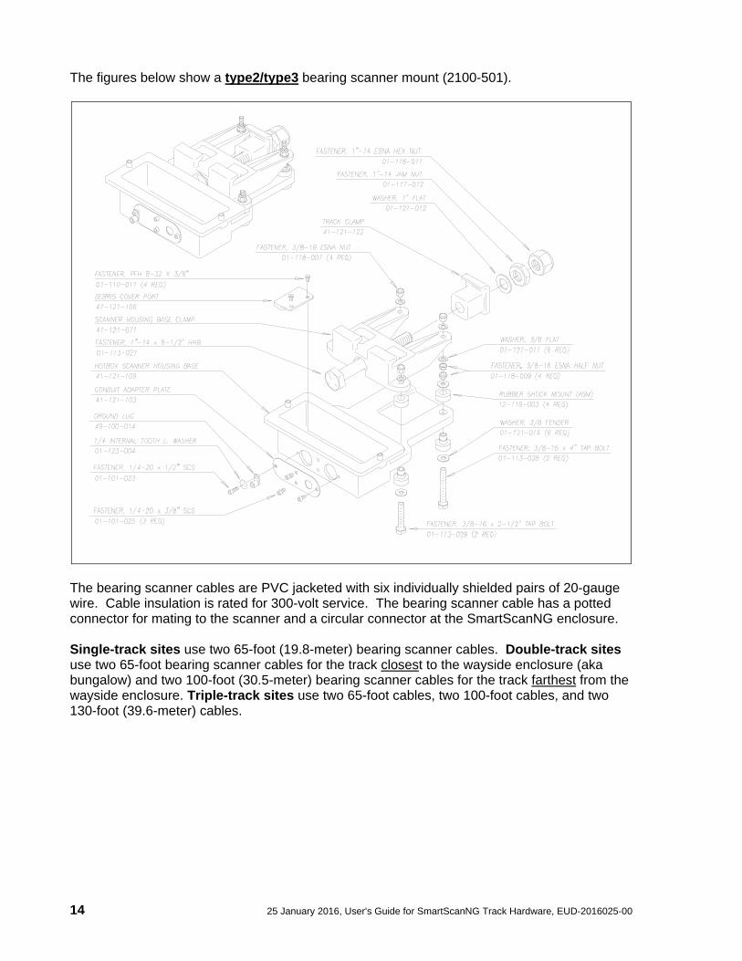
The figures below show a type2/type3 bearing scanner mount (2100-501).
The bearing scanner cables are PVC jacketed with six individually shielded pairs of 20-gauge wire. Cable insulation is rated for 300-volt service. The bearing scanner cable has a potted connector for mating to the scanner and a circular connector at the SmartScanNG enclosure. Single-track sites use two 65-foot (19.8-meter) bearing scanner cables. Double-track sites use two 65-foot bearing scanner cables for the track closest to the wayside enclosure (aka bungalow) and two 100-foot (30.5-meter) bearing scanner cables for the track farthest from the wayside enclosure. Triple-track sites use two 65-foot cables, two 100-foot cables, and two 130-foot (39.6-meter) cables.
EUD-2016025-00, User's Guide for SmartScanNG Track Hardware, 25 January 2016 15
The figure below shows a bearing scanner cable. The part number for the 65-foot (19.8-meter) bearing scanner cable is 2058-260PM. For the 100-foot (30.5-meter) cable, it's 2058-265PM. For the 130-foot (39.6-meter) cable, it's 2058-267PM.
2.3 Wheel Scanners The figure below shows a type2 wheel scanner cover-and-module assembly. The only difference between the type2 wheel scanner cover-and-module assembly and the one for the type2 bearing scanner is the addition of the plastic attenuation plug.
16 25 January 2016, User's Guide for SmartScanNG Track Hardware, EUD-2016025-00
The figure below shows a type3 wheel scanner cover-and-module assembly. The only difference between the wheel scanner cover-and-module assembly and the one for the bearing scanner is a change of filter frames. The wheel scanner uses a red filter frame. However, wheel scanners are shipped from the factory with black filter frames installed.
Weather Cover
Mounting Plate
Filter FrameRed for Wheel ScannerBlack for Bearing Scanner
EUD-2016025-00, User's Guide for SmartScanNG Track Hardware, 25 January 2016 17
The figure below shows a type2 wheel scanner mount (2100-701). Though not recommended, this mount can also be used for type3 wheel scanners. However, this guide does not cover the use of this mount for type3 wheel scanners.
18 25 January 2016, User's Guide for SmartScanNG Track Hardware, EUD-2016025-00
The figure below shows a type3 wheel scanner mount (2500-401) and its parts.
The figure below shows the wheel scanner cable. The only difference between the bearing scanner cable and the wheel scanner cable is a different flex-conduit-adapter plate. The one for the wheel scanner is smaller. (The part number for the 65-foot (19.8-meter) wheel scanner cable is 2058-260HW. For the 100-foot (30.5-meter) cable, it's 2058-265HW.)
Scanner Housing Base Clamp41-121-071
HHB 1-14 x 8-1/2"01-113-027
Locator Pin41-121-107, 2-Req.
1"NPT PVC Hex Pipe Plug34-100-050
1/4" Internal Tooth Lockwasher01-123-004, 2-Req.
SCS 1/4-20 x 1/2" S.Steel01-101-023, 2-Req.
T&B Solderless Lug #649-100-041
Hot Wheel Detector Base41-121-194
Tap Bolt 3/8-16 x 2-1/2"01-113-029, 2-Req.
Tap Bolt 3/8-16 x 4"01-113-028, 2-Req.
3/8 x 1"OD Gal. Flat Washer01-121-028, 4-Req.
Shock Mount (Pair)12-119-003, 4-Req.
3/8 Fender Washer x 1-1/4"OD01-121-014, 2-Req.
3/8-16 ESNA Half Nut01-118-009, 4-Req.
3/8 Flat Washer S.Steel01-121-011, 6-Req.
3/8-16 ESNA Nut01-118-007, 4-Req.
Cast Track Clamp41-121-122
1" Flat Washer Plated01-121-012
1-14 Hex Nut Jam01-117-012
1-14 ESNA Nut01-118-011
EUD-2016025-00, User's Guide for SmartScanNG Track Hardware, 25 January 2016 19
2.4 Scanner Alignment/Calibration Tools This section describes the components that are used during the adjustment process. Covered are the alignment fixture and the calibrated heat source. STC supplies one of each for each SmartScanNG site. Section 10.0 - Aligning Scanners and Section 12.0 – Calibrating Scanner tell how to use these components to establish proper scanner alignment and to set and verify the heat values seen by the scanners.
2.4.1 Alignment Fixture (2066-000) The figure below shows an assembled alignment fixture (2066-000).
20 25 January 2016, User's Guide for SmartScanNG Track Hardware, EUD-2016025-00
The figure below shows the parts of an alignment fixture (2066-000).
The alignment fixture is used to ensure that all scanners are aimed at the proper point above the rail. Each axis of the fixture is equipped with graduated scales that give indications relative to the top of the rail and the gauge.
EUD-2016025-00, User's Guide for SmartScanNG Track Hardware, 25 January 2016 21
The fixture is used differently for bearing scanners and for wheel scanners. To align bearing scanners, you use the optical system of the fixture. The key parts of this optical system are the target sight and the reflector block. Shown below is alignment of a bearing scanner.
To align wheel scanners, you use the horizontal alignment bar of the fixture. Alignment is done by measuring from the bottom of the extended bar to the top of both ends of the scanner mount. When both measurements are the same, alignment is correct. That is, as shown below, when distance A is equal to distance B, alignment is correct.
Alignment must be performed when a new scanner is installed. Thereafter, unless the scanner is damaged, it is unlikely that alignment will change once it has been set.
22 25 January 2016, User's Guide for SmartScanNG Track Hardware, EUD-2016025-00
The transducer height bracket on the bottom of the alignment fixture can be used to ensure proper installation of the transducers. When the transducer body touches the bracket, the transducer body is 1-9/16 inches (3.97 centimeters) below the top of the rail and parallel to it.
2.4.2 Calibrated Heat Source (2100-810NG) When a new scanner is installed, calibration is performed. Thereafter, calibration usually is done only when needed or on a regular basis during scheduled maintenance. The supplied calibrated heat source (2100-810NG) operates from a 120-volt 60-Hz power source. Minimum operating voltage is 105 volts. A frequency of 50 Hz won’t work. The supplied 16-gauge orange power cable provides the necessary safety ground. This cable is 50 feet (15 meters) long. If you need to add an extension cord to this cable, make sure it is 16-gauge or larger thickness of wire. For a site that doesn’t have a 120-volt 60-Hz power source, the heat source should be powered from a true sine wave inverter capable of 250 watts with an output of at least 110 volts at 60 Hz. The inverter should operate from an input voltage of 10.5 VDC to 15 VDC. A 120-volt USA socket should be provided to match the heat source power cord. The inverter should be grounded according to the manufacturer’s recommendations. On the front of the calibrated heat source is a knob that lets you select one of five delta temperatures, ranging from 126°F to 220°F. The heat source contains a heat block that can reach a combined temperature of your delta temperature plus the ambient temperature. It can maintain this temperature for extended periods. The heat block is controlled by a circuit that references both ambient temperature and the temperature of the heat block, and maintains the selected differential. For example, if the ambient temperature were 29.4°C (85°F) and the knob were set to 180°F (100°C), the heat block would be maintained at 129.4°C (265°F).
EUD-2016025-00, User's Guide for SmartScanNG Track Hardware, 25 January 2016 23
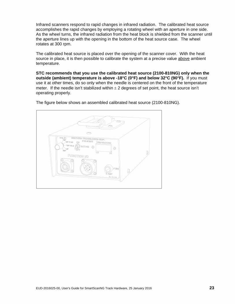
Infrared scanners respond to rapid changes in infrared radiation. The calibrated heat source accomplishes the rapid changes by employing a rotating wheel with an aperture in one side. As the wheel turns, the infrared radiation from the heat block is shielded from the scanner until the aperture lines up with the opening in the bottom of the heat source case. The wheel rotates at 300 rpm. The calibrated heat source is placed over the opening of the scanner cover. With the heat source in place, it is then possible to calibrate the system at a precise value above ambient temperature. STC recommends that you use the calibrated heat source (2100-810NG) only when the outside (ambient) temperature is above -18°C (0°F) and below 32°C (90°F). If you must use it at other times, do so only when the needle is centered on the front of the temperature meter. If the needle isn’t stabilized within 2 degrees of set point, the heat source isn’t operating properly. The figure below shows an assembled calibrated heat source (2100-810NG).
24 25 January 2016, User's Guide for SmartScanNG Track Hardware, EUD-2016025-00
The figure below shows the parts of a calibrated heat source (2100-810NG).
EUD-2016025-00, User's Guide for SmartScanNG Track Hardware, 25 January 2016 25
2.4.2.1 Heat Source Front Panel The figure below shows the control panel that's on the front of a calibrated heat source (2100-810NG).
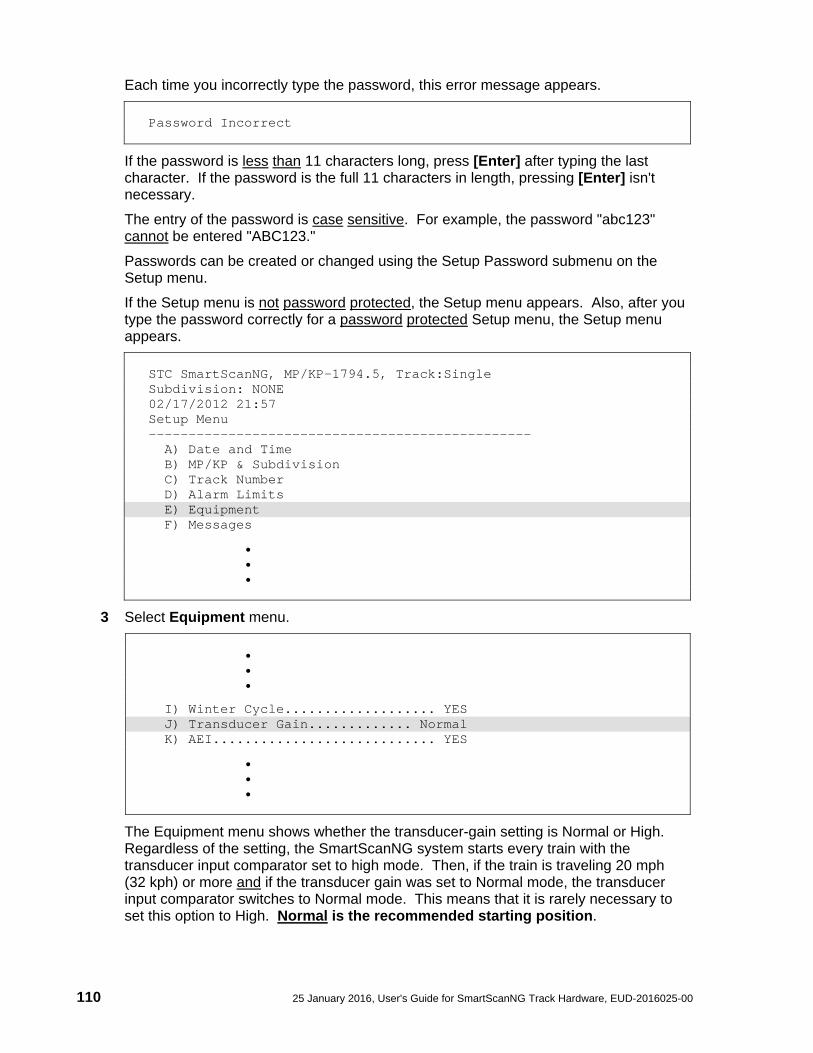
Temperature Knob The temperature knob allows you to select one of five delta temperatures. The temperature label on each knob setting represents degrees Fahrenheit above ambient. The 180 setting is normally used with all STC scanners. Gating Switch On the front of the heat source is the Gating switch. Toggling it on causes gating signals to be sent to the Function I/O connectors. The first signal sent is a simulated TO1 (aka A-transducer) signal. The second signal sent is a simulated TO2 (aka B-transducer) signal. As long as this switch is toggled on, this sequence continues at a rate of 10 signals per second (five of them being TO1s and five of them being TO2s). The gating signals aren't needed for calibration of the SmartScanNG system. The Gating switch may be left in the off position. Temperature Meter The temperature meter shows when heat block has reached the selected temperature setting and has stabilized within 2 degrees of set point. From a cold start, this could take 5 to 8 minutes. The heat block is stabilized when the needle is centered. Function Connectors The function connectors provide the I/O lines to the heat source including AC power in and gating signals out. The six-contact circular connector (on the left side) is compatible with the power cord included with the system. One end of the supplied 2100-832 power cord is connected to the heat source. The other end is plugged into a stable, grounded, three-wire AC outlet capable of at least 105 VAC at 15 amperes.
FUNCTION I/O
130° BOLO
SOUTHERN TECHNOLOGIES CORP.
220°126°
180°DEG. (F)
130° PYRO
LO
2100-810NG
GATING
OFF
ON
HI
FUSE
TEMPERATURE
2 AMP
26 25 January 2016, User's Guide for SmartScanNG Track Hardware, EUD-2016025-00
The table below shows the pin assignment for the six-contact connector. Pin Assignment A AC Neutral B AC Hot C AC Ground D TO1 (positive output pulse) E TO2 (positive output pulse) F Ground
The eight-contact circular connector (on the right side) isn't used when calibrating STC scanners. For safety's sake, always cover this connector with the supplied dust cap. Fuse On the front of the heat source is a 2-amp 250-volt fast-acting fuse. It protects the heat source from excessive current.
2.4.2.2 Modification for Use with Type3 Wheel Scanner For Type3 hot wheel scanners mounted on 115-LB rail: Sometimes interference issues occur between the crown of rail and the power connector on the 2100-810NG heat source. This condition makes it impossible to calibrate the wheel scanner because the heat source cannot be properly seated on the scanner cover. If you experience this or other clearance issues, your heat source will need to be modified. This section outlines those modification procedures.
EUD-2016025-00, User's Guide for SmartScanNG Track Hardware, 25 January 2016 27
Modification Procedure 1. Open the heat-source by removing the lid.
2. Disconnect the 12-pin Molex connector.
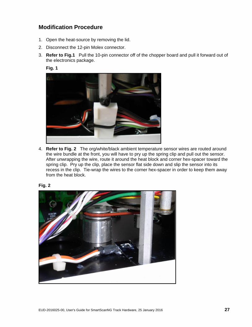
3. Refer to Fig.1 Pull the 10-pin connector off of the chopper board and pull it forward out of the electronics package.
Fig. 1
4. Refer to Fig. 2 The org/white/black ambient temperature sensor wires are routed around the wire bundle at the front, you will have to pry up the spring clip and pull out the sensor. After unwrapping the wire, route it around the heat block and corner hex-spacer toward the spring clip. Pry up the clip, place the sensor flat side down and slip the sensor into its recess in the clip. Tie-wrap the wires to the corner hex-spacer in order to keep them away from the heat block.
Fig. 2
28 25 January 2016, User's Guide for SmartScanNG Track Hardware, EUD-2016025-00
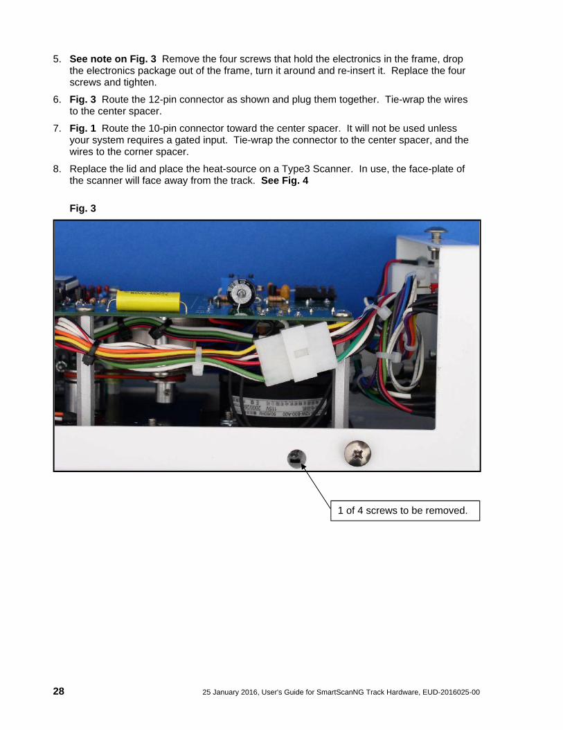
5. See note on Fig. 3 Remove the four screws that hold the electronics in the frame, drop the electronics package out of the frame, turn it around and re-insert it. Replace the four screws and tighten.
6. Fig. 3 Route the 12-pin connector as shown and plug them together. Tie-wrap the wires to the center spacer.
7. Fig. 1 Route the 10-pin connector toward the center spacer. It will not be used unless your system requires a gated input. Tie-wrap the connector to the center spacer, and the wires to the corner spacer.
8. Replace the lid and place the heat-source on a Type3 Scanner. In use, the face-plate of the scanner will face away from the track. See Fig. 4
Fig. 3
1 of 4 screws to be removed.
EUD-2016025-00, User's Guide for SmartScanNG Track Hardware, 25 January 2016 29
Fig. 4
Before Modification
After Modification
30 25 January 2016, User's Guide for SmartScanNG Track Hardware, EUD-2016025-00
2.4.2.3 Heat Source: Power Cable Warning A few years ago the power cord connector was found to be a shock hazard because the connector had pins that might be easy to touch if someone were not paying attention. If the power cord were plugged in to AC that would be a startling experience! So the connectors on both the power cord and the heat source were changed. Because of that change a new power cord was and is shipped with each new heat source.
Old style plug with pins. New heat source with pins. As you can see, even though the connectors will fit together, they won’t work together. When the connectors are screwed together the two sets of pins touch and cause a reverse polarity situation which damages the heat source.
Warning - Caution PLEASE – ONLY USE THE POWER CORD THAT WAS SHIPPED WITH
THIS HEAT SOURCE. USE OF THE OLD CORD WITH PINS IN THE CONNECTOR WILL DAMAGE THIS
HEAT SOURCE
EUD-2016025-00, User's Guide for SmartScanNG Track Hardware, 25 January 2016 31
3.0 Transducers
3.1 Transducers Transducers are rail-mounted devices that provide the timing signals that allow the system to:
Detect a train's presence
Coordinate gating
Determine a train's direction
Calculate a train's exit speed
Calculate a train's length
Identify individual railcars and locomotives based on axle spacing patterns Two mounting plates are packaged with each transducer. The smaller one, which is labeled 112LB-130LB, is used with lighter rails. The larger one, which is labeled 131LB-141LB, is used with heavier rails. If your rail size were 112 to 130-pounds per yard (55.6 to 64.5-kilograms per meter), you would use the smaller mounting plate (2100-554) that looks like this.
If your rail size were 131 to 141-pounds per yard (65.0 to 69.9-kilograms per meter), you would use the larger mounting plate (2100-552) that looks like this.
112LB-130LB
131LB-141LB
32 25 January 2016, User's Guide for SmartScanNG Track Hardware, EUD-2016025-00
The figure below shows an assembled transducer with the larger mounting plate.
The figure below shows the parts of a transducer with the smaller mounting plate.
STC transducers consist of a horseshoe magnet with a tightly wound coil, encapsulated in a rigid epoxy potting compound. Each transducer is mounted 1-9/16 inches (3.97 centimeters) below the top of the rail. As the wheels of a railcar pass over the transducer, the wheel flange disturbs the flux field of the magnet, causing the output of a sinusoidal type waveform of varying amplitude. The depth of the flange and the speed at which the wheel is moving determines amplitude.
EUD-2016025-00, User's Guide for SmartScanNG Track Hardware, 25 January 2016 33
The STC magnetic transducer can be utilized in two different functions on a SmartScanNG system - as a gating transducer or an advance transducer. All tracks use two rail-mounted gating transducers. On the rail nearest the wayside enclosure, these transducers (labeled TO1 and TO2) are mounted near and to the north or east of the bearing scanner. They control scan timing and car recognition. Some but not all tracks use rail-mounted advance transducers (labeled ADV1 and ADV2). On the rail nearest the wayside enclosure, the two advance transducers are usually mounted 32 feet (9.75 meters) on either side of the gating transducers. If so desired, they can also be mounted 40 feet (12.19 meters) on either side of the gating transducers. The first advance transducer encountered provides a signal that changes the state of an inactive system from idle to scan mode. Instead of two advance transducers, train presence can be ascertained by using a track circuit and an SOTC board. The figure below shows a transducer cable.
One end of the transducer cable comes attached to the transducer. The other end has two wires protruding from the conduit. These wires are black and white. They attach to a surge protector located on the surge-protection panel. There is one surge protector assigned to transducer TO1 and another to transducer TO2. These surge protectors protect the SmartScanNG system from transients and surges, which can be induced onto external wiring by lightning.
34 25 January 2016, User's Guide for SmartScanNG Track Hardware, EUD-2016025-00
3.2 Transducer Alignment Tools The figure below shows an assembled alignment fixture (2066-000).
The transducer height bracket on the bottom of the alignment fixture can be used to ensure proper installation of the transducers. When the transducer body touches the bracket, the transducer body is 1-9/16 inches (3.97 centimeters) below the top of the rail and parallel to it.
EUD-2016025-00, User's Guide for SmartScanNG Track Hardware, 25 January 2016 35
4.0 Deflectors
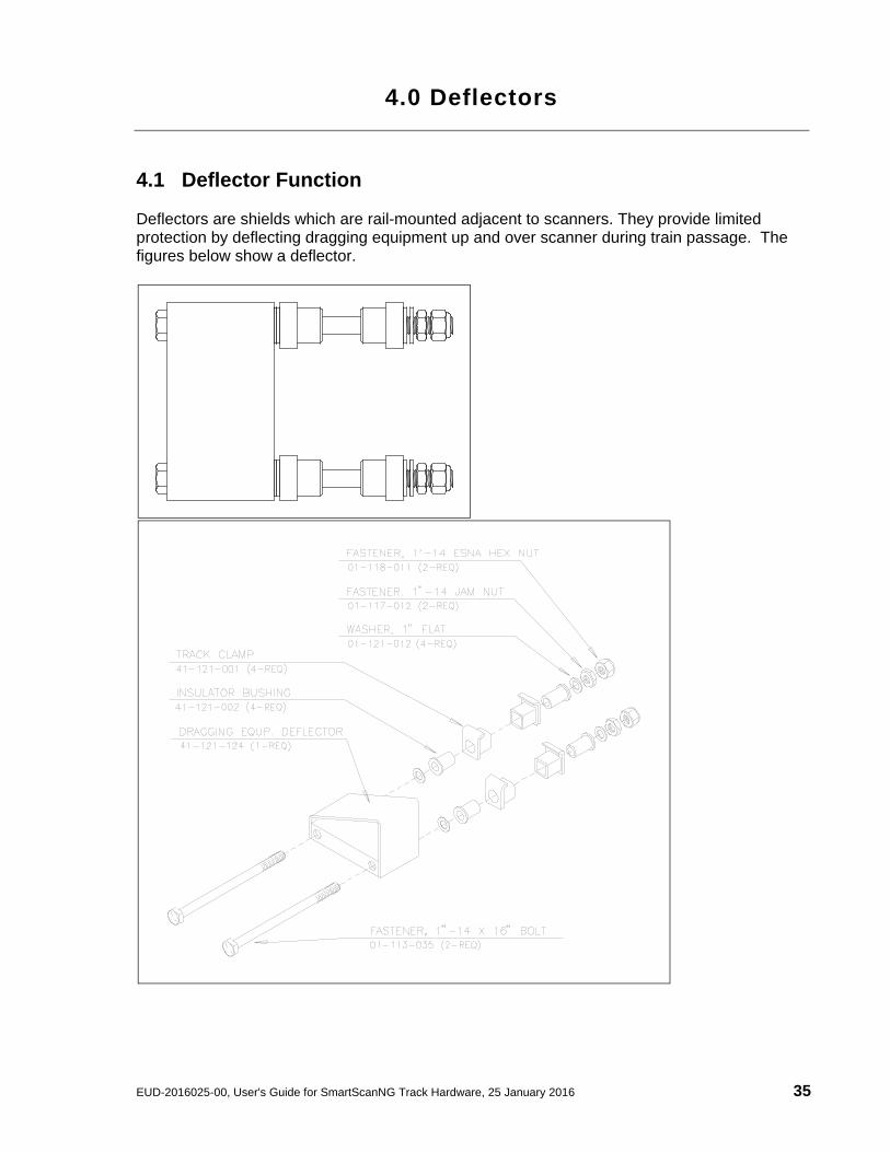
4.1 Deflector Function Deflectors are shields which are rail-mounted adjacent to scanners. They provide limited protection by deflecting dragging equipment up and over scanner during train passage. The figures below show a deflector.
36 25 January 2016, User's Guide for SmartScanNG Track Hardware, EUD-2016025-00
EUD-2016025-00, User's Guide for SmartScanNG Track Hardware, 25 January 2016 37
5.0 Track Circuit
5.1 Track Circuit Some SmartScanNG sites use a track circuit to detect train presence. Other sites use advance transducers for this purpose. The track circuit combined with the SOTC board make up the presence subsystem. The track circuit is nothing more than two wires attached to the rails. One wire is attached to each rail. When the SOTC board senses a track shunt, it signals the SmartScanNG system that a train is present. The shunting zone is adjustable up to 150 feet (45.7 meters) on each side of the attached track-circuit wires. The track circuit wires are attached to each rail directly opposite from the other, centered between the gating transducers. Connection to the rail can be made in one of two ways.
Bonding – Cadweld manufactures a line of bond welding systems that are commonly used by railroads. Recommended practice is to weld a short length of bond strand to the web of each rail. Cadweld can provide these items as prepackaged kits, which include the bond strand (a 3/16-inch (4.8-millimeter) diameter strand is recommended) and the one-shot welding system. A reusable mold of the correct size is required.
Drilling – The alternative to Cad-welding is to drill a 3/8-inch (9.5-millimeter) hole in the web of each rail at the neutral axis, and apply a bonding kit. The kit includes ready-made lengths of bond strand with "chicken heads" attached. The "chicken heads" are tapered solid metal inserts that can be driven into the 3/8-inch (9.5-millimeter) holes to establish a permanent connection to the rail.
Once the rail attachment is made, extend the connection to the three-terminal arrester mounted below the SmartScanNG enclosure. You do this by splicing a length of wire to each bond strand. Okonite Cable makes a twisted-pair cable (Okonite 113-12-3933) that is suitable for direct burial. The cable has two 6-AWG solid conductors and a very rugged insulation jacket. The cable should be attached to the bond strand using compression sleeves.
38 25 January 2016, User's Guide for SmartScanNG Track Hardware, EUD-2016025-00
EUD-2016025-00, User's Guide for SmartScanNG Track Hardware, 25 January 2016 39
6.0 Auxiliary-Alarm Detectors
6.1 Auxiliary-Alarm Detectors The standard SmartScanNG system can support input from as many as four external alarm devices. Any device that provides an open set of relay contacts upon alarm detection can be supported by the system. Electrical contacts on auxiliary-alarm equipment should have a minimum current rating of less than 17 mA. The system responds to an open contact by announcing the defect and the axle number nearest the defect. Alarm detection and announcement are in real-time. The SmartScanNG system supports dragging-equipment alarms, high-load alarms, and wide-load alarms. Other alarm devices require custom speech programming. STC doesn't manufacture any auxiliary-alarm input devices. Therefore, their installation, use, and maintenance aren't covered in this manual.
40 25 January 2016, User's Guide for SmartScanNG Track Hardware, EUD-2016025-00
EUD-2016025-00, User's Guide for SmartScanNG Track Hardware, 25 January 2016 41
7.0 Antennas
7.1 AEI Antennas Not all SmartScanNG systems use the AEI (Automatic Equipment Identification) subsystem. If your SmartScanNG system does, the AEI subsystem consists of the AEI antennas, which are described below, and the AEI Interface module. The SmartScanNG system supports two types of antennas.
Sinclair SRL470 antennas
Scala HP9-915 Parapanel antennas
7.1.1 Sinclair SRL470 Antennas Two Sinclair SRL470 antennas (or two Scala HP9-915 Parapanel antennas) are installed per track. The SRL470 is a directionally-pointed horizontally-polarized panel antenna. It is housed in a compact white enclosure that is made from materials that don't interfere with the transmission and reception of radio waves. It is suitable for pipe, tower, or wall mounting.
In reference to the track, antenna0 is the northmost or eastmost antenna. Antenna1 is the southmost or westmost antenna. Each SRL470 antenna is installed:
With its face parallel to the rails
With its N-type connector pointing down
10 feet (3 meters) from the gauge side of the closest rail
3.5 feet (1.1 meters) above the top of the rails
Centered between the transducers
Opposite each other
42 25 January 2016, User's Guide for SmartScanNG Track Hardware, EUD-2016025-00
7.1.2 Scala HP9-915 Parapanel Antennas Two Scala HP9-915 Parapanel antennas (or two Sinclair SRL470 antennas) are installed per track. The HP9-915 is a directionally-pointed horizontally-polarized panel antenna. It has a gain of 9.5 dBd. It is housed in a compact white enclosure that is made from materials that don't interfere with the transmission and reception of radio waves. It is suitable for either pipe or tower mounting.
In reference to the track, antenna0 is the northmost or eastmost antenna. Antenna1 is the southmost or westmost antenna. Each HP9-915 antenna is installed:
Vertically with its face parallel to the rails
10 feet (3 meters) from the gauge side of the closest rail
3.5 feet (1.1 meters) above the top of the rails
Centered between the transducers
Opposite each other
Install Mounting Brackets
Type-N Connector
Rear
Top
EUD-2016025-00, User's Guide for SmartScanNG Track Hardware, 25 January 2016 43
8.0 Site Preparation The preparation phase starts with selecting the site. It ends with identifying the installation tools. Care taken during this phase can result in reduced maintenance and improved performance of the SmartScanNG system. This section covers what needs to be done before installation begins. Contained herein is time-tested advice that is well worth following.
8.1 Selecting a Site Locate the site:
On level, well-drained ground (avoid low areas where flooding may occur)
In an area that doesn't normally require heavy braking by passing trains
At least 300 feet (91.4 meters) from the nearest road crossing
Away from a track joint, a track switch, and a side track
By a track that is on gauge (avoid placing track hardware in curves)
By a roadbed that is tamped, stable, and well maintained
Where trains usually travel at more than 10 mph (16 kph)
8.2 Preparing the Scanner Location To ready the scanner location:
1 Select a location to install the bearing scanners.
2 Inspect the ties (aka sleepers) and tie plates (aka sleeper plates) in the area where the scanners are to be installed.
3 If the ties or tie plates aren't in good condition, fix this problem before proceeding.
4 If the ties aren't well tamped, fix this problem before proceeding.
5 Measure the distance between the ties.
The scanners should be centered in the crib of two ties spaced at least 14 inches (35.6 centimeters) apart.
6 If the ties aren’t spaced at least 14 inches (35.6 centimeters) apart, fix this problem before proceeding.
44 25 January 2016, User's Guide for SmartScanNG Track Hardware, EUD-2016025-00
7 Mark the rail at the midpoint between the ties.
If you are going to install antenna masts, in addition to identifying where the bearing scanners will be installed, this midpoint mark will also be used later to locate where the holes for the mast bases are to be dug.
8 If your installation has wheel scanners:
a Select a location to install them.
The wheel scanners should be centered in the crib of the two ties immediately ahead (and to the north or east) of the bearing scanners.
b Repeat steps 2 through 6.
8.3 Preparing the AEI Antenna Masts If your single-track site uses AEI equipment, to ready the masts (aka poles):
1 Using the dimensions below, dig two holes and add ballast.
EUD-2016025-00, User's Guide for SmartScanNG Track Hardware, 25 January 2016 45
2 Lower one metal mast base into each hole, rotating it until one edge of the base is parallel to the track.
Install each base so that it's plumb and so that its center is 10 feet (3 meters) from the gauge side of the closest rail and 25 inches (0.6 meters) from the center of the crib in which the bearing scanner will be installed. Both bases will be north or east of the crib.
3 With the supplied hardware, attach one mast to each base.
4 Plumb each mast.
5 Ground each mast.
When done, each mast should be level, grounded, attached to a base, and placed directly opposite the other mast.
8.4 Receiving Your System All the dragging-equipment detectors that a site needs are shipped on one pallet. All the components that make up one or more SmartScanNG systems are shipped either in a crate or in a wayside enclosure, if one was ordered. The contents of this crate or wayside enclosure are specific to the site and are detailed on the packing list. When the packages arrive at the site, check them immediately for exterior damage. If there is any, notify STC.
46 25 January 2016, User's Guide for SmartScanNG Track Hardware, EUD-2016025-00
8.5 Returning Damaged or Defective Hardware Return any damaged or defective hardware to STC for repair or replacement. You don't need a return authorization number. You don't need to call first. Just ship it directly to:
Southern Technologies Corporation Repair Department 6145 Preservation Drive Chattanooga, Tennessee 37416-3638 USA
With the returned hardware, include:
Complete address of where the hardware is to be returned.
Name and telephone number of the person who should be contacted to answer questions about the hardware.
Written explanation of the hardware damage or defect.
8.6 Getting Help with the Installation If a part is missing or if you have any problems installing a part, telephone STC's engineering staff. Except on major holidays, you can reach them at 423-892-3029, Monday through Friday, from 8:00 a.m. until 5:00 p.m. Eastern time. After business hours, calls are answered by machine. These calls are returned promptly the next business day. When calling, state that you are calling about a SmartScanNG system. Your call will then be directed to the appropriate person. Though slower and more cumbersome, solving your problems by email is also possible.
EUD-2016025-00, User's Guide for SmartScanNG Track Hardware, 25 January 2016 47
8.7 Identifying the Installation Tools Besides the tools needed to install signal cases, underground cables, and power services, you need these to install your SmartScanNG system.
Laptop computer
Track drill with 3/8-inch bit
1/2-inch drive socket with 9/16-inch deep well socket
3/4-inch drive socket with 1-7/16-inch socket
9/16-inch torque wrench
Medium size adjustable box wrench
Carpenters level
1/2-inch nutdriver
11/32-inch nutdriver
#2 Phillips head screwdriver
Small slotted screwdriver (aka flathead screwdriver)
50-foot (15-meter) or longer tape measure
Multimeter, reading at least 110 to120-VAC, 0 to 50-VDC, and 0 to 1-megohm In the box containing the bearing scanners are these tools.
Short-handle 1-1/2-inch open-end wrench, which is used to install the scanner mounts and the deflectors
T-handle 3/16-inch hex-wrench, which is used to install the flex-conduit-adapter plates on the scanner mounts
T-handle 1/4-inch hex-wrench, which is used to install the scanners on the scanner mounts
Two combination 9/16-inch open-end box wrenches, which are used to install the transducers and align the scanners
When you finish using the supplied tools, store them in the wayside enclosure, if possible. They are also used to maintain the system.
48 25 January 2016, User's Guide for SmartScanNG Track Hardware, EUD-2016025-00
EUD-2016025-00, User's Guide for SmartScanNG Track Hardware, 25 January 2016 49
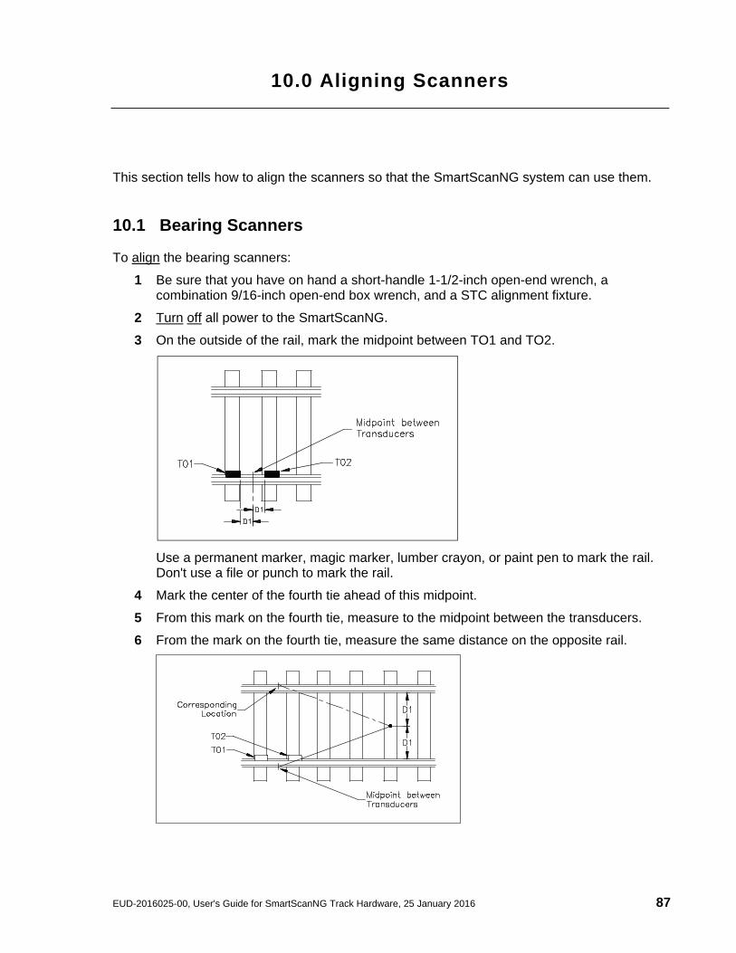
9.0 Installing Track Components
This section provides instruction for the installation of scanners, transducers, deflectors, track circuits, and AEI antennas. The installation of dragging-equipment detectors and other auxiliary-alarm detectors isn't covered in this guide. All SmartScanNG sites have two bearing scanners per track. Some tracks also have two wheel scanners. All tracks have two gating transducers. They are used to control scan timing and car recognition. All tracks have either two advance transducers or a track circuit used to indicate train presence. Track components are installed in this order.
Bearing scanners and their cables
Gating transducers and their cables
Advance transducers or Track Circuit
When used, wheel scanners and their cables
When used, deflectors
When used, AEI antennas and their cables
When used, auxiliary-alarm detectors and their cables
9.1 Bearing Scanners An assembled type2 bearing scanner looks like this.
50 25 January 2016, User's Guide for SmartScanNG Track Hardware, EUD-2016025-00
An assembled type3 bearing scanner looks like this.
To install the type2/type3 bearing scanners:
1 Be sure that you have on hand two assembled bearing scanners.
2 Be sure that you have on hand a short-handle 1-1/2-inch open-end wrench, a T-handle 3/16-inch hex-wrench, a T-handle 1/4-inch hex-wrench, a #2 Phillips head screwdriver, and a 50-foot (15-meter) or longer tape measure.
3 Select a location to install the bearing scanners.
The bearing scanners should be centered in the crib of two ties spaced at least 14 inches (35.6 centimeters) apart.
4 Under both rails between the ties, remove the ballast to a depth of 4 inches (10.1 centimeters).
You'll next install the first bearing scanner.
5 Using a T-handle 1/4-inch hex-wrench, loosen the socket-head-cap screws on the cover of a not-yet-installed bearing scanner.
The type2 bearing scanner has two socket-head-cap screws that attach the weather cover to the mount.
Weather Cover
EUD-2016025-00, User's Guide for SmartScanNG Track Hardware, 25 January 2016 51
The type3 bearing scanner has six socket head cap screws. Four that attach the weather cover to the mounting plate and two that attach the mounting plate to the mount.
6 Separate the bearing scanner cover-and-module assembly from its mount.
7 If this is a type3 bearing scanner, disconnect the heater wiring plug.
8 Store the cover-and-module assembly in a safe place until you replace it.
In the steps that follow, the terms track clamp, clamping nut, and locking nut are used. Notice where they are on the mount.
9 Centered between the ties and on the rail closest to the wayside enclosure, place the mount so that the moveable track clamp extends under the rail and toward the center of the track.
10 Tighten the inner nut (that is, the clamping nut) by hand.
This should hold the mount in place.
Weather Cover Mounting Plate
52 25 January 2016, User's Guide for SmartScanNG Track Hardware, EUD-2016025-00
11 Using a short-handle 1-1/2-inch wrench, tighten the clamping nut to a torque of 48 to 50 foot-pounds (65.1 to 67.8 newton-meters).
Don’t exceed a torque of 50 foot-pounds (67.8 newton-meters). Doing so can cause failure of the mount.
12 Using a short-handle 1-1/2-inch wrench, tighten the locking nut to a torque of 48 to 50 foot-pounds (65.1 to 67.8 newton-meters).
Don’t exceed a torque of 50 foot-pounds (67.8 newton-meters). Doing so can cause failure of the mount.
At this point, your work should look like this.
13 Determine the direction of scan. NOTE: On a N/S track, it is critical that bearing scanners be oriented to scan in a northerly direction. This reduces the possibility of scanners looking directly into the sun during scanning operations. For E/W tracks, an easterly direction of scan is considered the system “standard” and is strongly recommended by STC.
If the track runs north and south, both the oval hole in the top of the scanner and the rectangular hole in the bottom of the mount should be pointed north.
If the track runs east and west, both holes should be pointed east.
EUD-2016025-00, User's Guide for SmartScanNG Track Hardware, 25 January 2016 53
14 Examine the top of the mount.
In the bottom of the mount are two rectangular holes called debris ports. One port is covered. One isn't. Do the next step only if the uncovered debris port is at the southmost or westmost end of the mount.
15 If the debris port cover isn't as shown above, follow these steps.
a Using a #2 Phillips head screwdriver, remove the two screws holding the debris port cover.
b With gentle pushing from underneath, remove the debris port cover.
c Place the debris port cover over the debris port on the other end of the mount.
d Using a #2 Phillips head screwdriver, replace the two screws through the debris port cover.
16 If you are installing a type3 bearing scanner, follow these steps.
a Place the vented debris port cover over the debris port.
b Using a #2 Phillips head screwdriver and the supplied two screws, secure to mount.
Direction of Scan (North or East)
Vented Debris Port Cover
54 25 January 2016, User's Guide for SmartScanNG Track Hardware, EUD-2016025-00
17 Examine the side of the mount farthest from the track.
On the side of the mount are two large holes and four socket-head-cap screws. The longest screw is holding a ground lug and an internal-tooth washer.
18 Using a T-handle 3/16-inch hex-wrench, remove the four socket-head-cap screws.
19 Store the screws, washer, and lug in a safe place until you replace them.
In the steps that follow, the terms scanner cable connector, panel connector, and flex-conduit-adapter plate are used. Notice where they are on a bearing scanner cable.
Single-track sites have two 65-foot (19.8-meter) bearing scanner cables. Double-track sites have two 65-foot bearing scanner cables for the track closest to the wayside enclosure and two 100-foot (30.5-meter) bearing scanner cables for the track farthest from the wayside enclosure. Triple-track sites have two 65-foot cables, two 100-foot cables, and two 130-foot (39.6-meter) cables.
20 If this is a multitrack site, select the correct length of cable.
EUD-2016025-00, User's Guide for SmartScanNG Track Hardware, 25 January 2016 55
21 Tighten the locking nut (on the conduit connector) until it is tight against the flex-conduit-adapter plate
22 Put the scanner cable connector through the northmost or eastmost round hole in the side of the mount.
23 Align the screw holes in the flex-conduit-adapter plate with the screw holes in the mount.
24 Replace the two center screws and tighten by hand.
This should hold the flex-conduit-adapter plate in place.
25 Leave 6 inches (15.2 centimeters) of the bearing scanner cable in the mount.
26 In the screw hole closest to the cable, replace the screw and tighten by hand.
27 In the screw hole farthest from the cable, replace the ground lug, internal-tooth washer, and screw.
28 Tighten by hand.
29 Using a T-handle 3/16-inch hex-wrench, tighten the four screws until they are completely tight.
30 Attach the bearing scanner cable connector to the scanner box connector.
56 25 January 2016, User's Guide for SmartScanNG Track Hardware, EUD-2016025-00
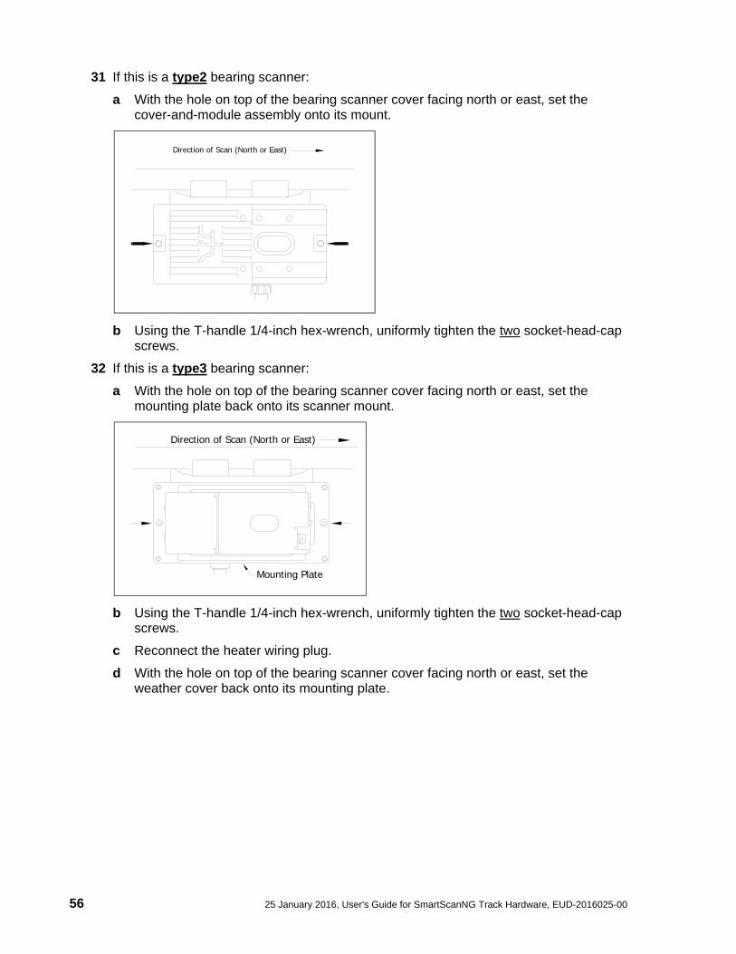
31 If this is a type2 bearing scanner:
a With the hole on top of the bearing scanner cover facing north or east, set the cover-and-module assembly onto its mount.
b Using the T-handle 1/4-inch hex-wrench, uniformly tighten the two socket-head-cap screws.
32 If this is a type3 bearing scanner:
a With the hole on top of the bearing scanner cover facing north or east, set the mounting plate back onto its scanner mount.
b Using the T-handle 1/4-inch hex-wrench, uniformly tighten the two socket-head-cap screws.
c Reconnect the heater wiring plug.
d With the hole on top of the bearing scanner cover facing north or east, set the weather cover back onto its mounting plate.
Direction of Scan (North or East)
Mounting Plate
Direction of Scan (North or East)
EUD-2016025-00, User's Guide for SmartScanNG Track Hardware, 25 January 2016 57
e Using the T-handle 1/4-inch hex-wrench, uniformly tighten the four socket-head-cap screws.
33 If this is a single-track site, label the end of the cable that isn't attached to the bearing scanner RAIL1 or RAIL2, whichever is appropriate.
If the track runs north and south, RAIL1 is the east rail and RAIL2 is the west rail. If the track runs east and west, RAIL1 is the north rail and RAIL2 is the south rail.
34 If this is a double-track site, label the end of the cable that isn't attached to the bearing scanner RAIL1-TRACK1, RAIL2-TRACK1, RAIL1-TRACK2, or RAIL2-TRACK2, whichever is appropriate.
35 If this is a triple-track site, label the end of the cable that isn't attached to the bearing scanner RAIL1-TRACK1, RAIL2-TRACK1, RAIL1-TRACK2, RAIL2-TRACK2, RAIL1-TRACK3, or RAIL2-TRACK3, whichever is appropriate.
36 Extend the cable into the wayside enclosure and leave it coiled on the floor.
37 Attach one end of an 8-AWG stranded copper wire to the ground lug on the flex-conduit-adapter plate and the other end to the ground connector on the ground rod.
The ground rod was driven into the ground beside the wayside enclosure.
You'll next install the second bearing scanner on the opposite rail.
38 Using a T-handle 1/4-inch hex-wrench, loosen the socket-head-cap screws on the cover of the remaining not-yet-installed bearing scanner.
The type2 bearing scanner has two socket-head-cap screws that attach the weather cover to the mount. The type3 bearing scanner has six. Four that attach the weather cover to the mounting plate and two that attach the mounting plate to the mount.
39 Separate the scanner cover-and-module assembly from its mount.
40 If this is a type3 bearing scanner, disconnect the heater wiring plug.
41 Store the cover-and-module assembly in a safe place until you replace it.
When installing the second bearing mount on the opposite rail, make sure that the two bearing mounts are squared with each other and directly opposite each other. The next step tells how to do this.
42 To locate the second mount on the opposite rail:
a Mark the center of the fourth tie ahead of the just installed mount.
Weather Cover
Direction of Scan (North or East)
58 25 January 2016, User's Guide for SmartScanNG Track Hardware, EUD-2016025-00
b From this mark, measure to the edge of the track clamp on the just installed mount.
c From the mark, measure the same distance on the opposite rail.
d Mark this location.
This mark will correspond to the edge of the track clamp on the opposite mount.
Use a permanent marker, magic marker, lumber crayon, or paint pen to mark the rail. Don't use a file or punch to mark the rail.
43 With the mark as a guide, place the second mount so that the moveable track clamp extends under the rail and toward the center of the track.
44 Repeat steps 10 through 36.
45 Attach one end of an 8-AWG stranded copper wire to the ground lug on the flex-conduit-adapter plate and the other end to the ground lug on the other scanner mount.
Seen from above, your site would look something like this.
46 If this is a multitrack site, repeat steps 1 through 45 on each track.
EUD-2016025-00, User's Guide for SmartScanNG Track Hardware, 25 January 2016 59
9.2 Transducers An assembled STC magnetic transducer looks like one of these.
If your site uses transducers that don’t look like either of the above, skip the instructions below and call STC for help. If your rail size isn’t 115, 122, 127, 132, 136, or 141-pounds per yard (57.05, 60.52, 63.00, 65.48, 67.46, or 69.94-kilograms per meter), skip the instructions below and call STC for help. Two mounting plates are packaged with each transducer. The smaller one, which is labeled 112LB-130LB, is used with lighter rails. The larger one, which is labeled 131LB-141LB, is used with heavier rails. If your rail size is 112 to 130 pounds per yard (55.6 to 64.5 kilograms per meter), use the smaller mounting plate (2100-554) that looks like this.
If your rail size is 131 to 141 pounds per yard (65.0 to 69.9 kilograms per meter), use the larger mounting plate (2100-552) that looks like this.
112LB-130LB
131LB-141LB
60 25 January 2016, User's Guide for SmartScanNG Track Hardware, EUD-2016025-00
9.2.1 Gating Transducers To install the gating transducers with their correct mounting plates:
1 Be sure that you have on hand all the parts for two gating transducers.
2 Be sure that you have on hand a track drill, a 3/8-inch bit, a 9/16-inch torque wrench, a 50-foot (15-meter) or longer tape measure, and the alignment fixture.
3 Determine the size of the rail at your site.
If your rail size isn't 115, 122, 127, 132, 136, or 141-pounds per yard (57.05, 60.52, 63.00, 65.48, 67.46, or 69.94-kilograms per meter), call STC for help.
On the rail nearest to the wayside enclosure, you’ll next install the gating transducer nearest to the bearing scanner.
The graphic below depicts component placement for a “standard” north/south track configuration. A north-facing scanner is highly recommended to reduce the possibility of looking directly into the sun during scanning operations. The east rail is Rail1 and the west rail is Rail2. The northmost transducer is always designated TO2 regardless of which rail it is mounted to. The eastmost antenna is always designated Antenna-0.
TO2 (Gating Transducer)
TO1 (Gating Transducer)
N
S
W E
CTR of GATE
BEARINGSCANNER
WHEELSCANNER
DIRECTIONof SCAN
Antenna-1 Antenna-0
TRANSDUCER LAYOUT for NORTH-FACING SCAN
EUD-2016025-00, User's Guide for SmartScanNG Track Hardware, 25 January 2016 61
The graphic (below left) depicts component placement for the typical east/west track configuration. An east-facing scanner is considered “standard” and is recommended by STC. An alternative configuration (west-facing scanner) is depicted in the lower-right graphic. The north rail is Rail1 and the south rail is Rail2. In either configuration, the eastmost transducer is always designated TO2 regardless of which rail it is mounted to. The northmost antenna is always designated Antenna-0.
TO
2 (Gating
Tra
nsducer)
TO
1 (Gating
Tra
nsducer)
CT
R of G
AT
E
BE
AR
ING
SC
AN
NE
R
WH
EE
LS
CA
NN
ER
DIRECTIONof SCAN
Antenna-0
Antenna-1
N
S
W E
TRANSDUCER LAYOUT for EAST-FACING SCAN
TO
2 (G
ating
Tra
nsducer)
BE
AR
ING
SC
AN
NE
R
CT
R of G
AT
E
Antenna-0
Antenna-1
WH
EE
LS
CA
NN
ER
TO
1 (G
ating
Tra
nsducer)
N
S
W E
DIRECTIONof SCAN
TRANSDUCER LAYOUT for WEST-FACING SCAN
62 25 January 2016, User's Guide for SmartScanNG Track Hardware, EUD-2016025-00
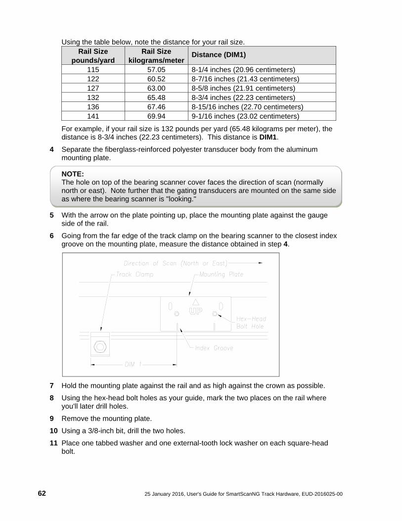
Using the table below, note the distance for your rail size. Rail Size
For example, if your rail size is 132 pounds per yard (65.48 kilograms per meter), the distance is 8-3/4 inches (22.23 centimeters). This distance is DIM1.
4 Separate the fiberglass-reinforced polyester transducer body from the aluminum mounting plate.
NOTE: The hole on top of the bearing scanner cover faces the direction of scan (normally north or east). Note further that the gating transducers are mounted on the same side as where the bearing scanner is "looking."
5 With the arrow on the plate pointing up, place the mounting plate against the gauge side of the rail.
6 Going from the far edge of the track clamp on the bearing scanner to the closest index groove on the mounting plate, measure the distance obtained in step 4.
7 Hold the mounting plate against the rail and as high against the crown as possible.
8 Using the hex-head bolt holes as your guide, mark the two places on the rail where you'll later drill holes.
9 Remove the mounting plate.
10 Using a 3/8-inch bit, drill the two holes.
11 Place one tabbed washer and one external-tooth lock washer on each square-head bolt.
EUD-2016025-00, User's Guide for SmartScanNG Track Hardware, 25 January 2016 63
12 Insert the two square-head bolts with tabbed washers and external-tooth lock washers into the slotted holes of the mounting plate.
13 With the arrow on the plate pointing up and the heads of the bolts against the gauge side of the rail, align the hex-head bolt holes in the plate with the drilled holes in the rail.
14 Place one Nord-Lock washer on each hex-head bolt.
15 Insert the two hex-head bolts with Nord-Lock washers through the aligned holes.
16 Loosely place the mounting bar, Nord-Lock washers, and hex-lock nuts onto the hex-head bolts.
TABBED WASHER
SQUARE-HEAD BOLT
LOCK WASHER
HEX-HEAD BOLT
NORD-LOCK WASHER
MOUNTING BARNORD-LOCK WASHER
HEX NUT
64 25 January 2016, User's Guide for SmartScanNG Track Hardware, EUD-2016025-00
17 Tighten each hex-lock nut with a 9/16-inch torque wrench to a torque of 12 to 15 foot-pounds (16.3 to 20.3 newton-meters).
Don't exceed a torque of 15 foot-pounds (20.3 newton-meters). Doing so can weaken or break a bolt, requiring the bolt to be replaced.
18 With the transducer body's magnetic side up (that is, with the arrow on the transducer body pointing up), slide it onto the square-head bolts.
19 Loosely place the Nord-Lock washers and hex-lock nuts onto the.. square-head bolts.
The installed transducer body should be 1-9/16 inches (3.97 centimeters) below the top of the rail and parallel to it. You can meet this requirement by using the transducer height bracket on the bottom of the alignment fixture.
20 Place the alignment fixture across both rails, centered over the transducer.
The fixture should be snug against the top and gauge of both rails.
21 Move the transducer body to where it just touches the height bracket.
22 Tighten each hex nut with a 9/16-inch torque wrench to a torque of 12 to 15 foot-pounds (16.3 to 20.3 newton-meters).
Don't exceed a torque of 15 foot-pounds (20.3 newton-meters). Doing so can weaken or break a bolt, requiring the bolt to be replaced.
The transducer body is now attached to the mounting plate.
EUD-2016025-00, User's Guide for SmartScanNG Track Hardware, 25 January 2016 65
23 If this is a single-track site, label the two-wire end of the cable TO1.
24 If this is a double-track site, label the two-wire end of the cable TO1-TRACK1 or TO1-TRACK2, whichever is appropriate.
25 Extend the cable into the wayside enclosure and leave it coiled on the floor.
You'll next install the gating transducer farthest from the bearing scanner. This transducer is TO2.
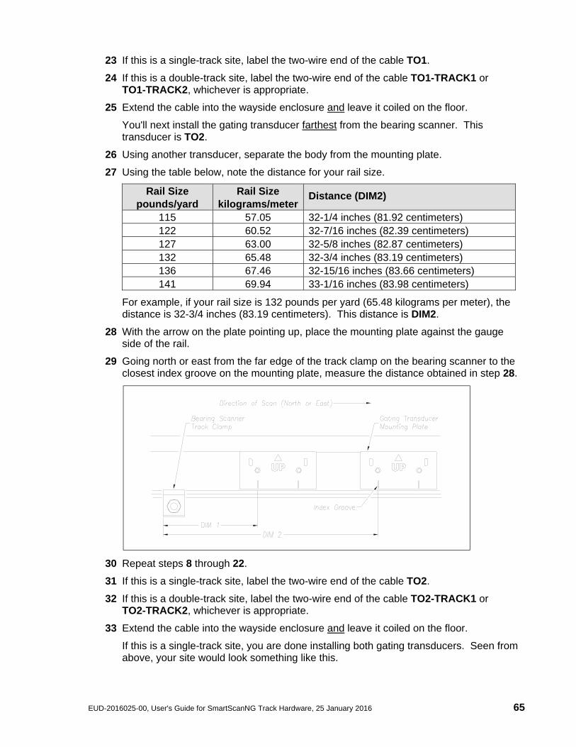
26 Using another transducer, separate the body from the mounting plate.
27 Using the table below, note the distance for your rail size.
For example, if your rail size is 132 pounds per yard (65.48 kilograms per meter), the distance is 32-3/4 inches (83.19 centimeters). This distance is DIM2.
28 With the arrow on the plate pointing up, place the mounting plate against the gauge side of the rail.
29 Going north or east from the far edge of the track clamp on the bearing scanner to the closest index groove on the mounting plate, measure the distance obtained in step 28.
30 Repeat steps 8 through 22.
31 If this is a single-track site, label the two-wire end of the cable TO2.
32 If this is a double-track site, label the two-wire end of the cable TO2-TRACK1 or TO2-TRACK2, whichever is appropriate.
33 Extend the cable into the wayside enclosure and leave it coiled on the floor.
If this is a single-track site, you are done installing both gating transducers. Seen from above, your site would look something like this.
66 25 January 2016, User's Guide for SmartScanNG Track Hardware, EUD-2016025-00
34 If this is a double-track site, repeat steps 1 through 34 on the second track.
9.2.2 Advance Transducers Not all sites use advance transducers. If your site uses a track circuit, skip ahead to next section. To install the advance transducers with their correct mounting plates:
1 Be sure that you have on hand all the parts for two advance transducers.
2 Be sure that you have on hand a track drill, a 3/8-inch bit, a 9/16-inch torque wrench, a 50-foot (15-meter) or longer tape measure, and the alignment fixture.
On the rail nearest the wayside enclosure, the two advance transducers are usually mounted 32 feet (9.75 meters) on either side of the gating transducers. If so desired, you can also mount them 40 feet (12.19 meters) on either side of the gating transducers.
EUD-2016025-00, User's Guide for SmartScanNG Track Hardware, 25 January 2016 67
You'll next install advance transducer ADV1 to the right of gating transducer TO2.
3 Separate the fiberglass-reinforced polyester transducer body from the aluminum mounting plate.
4 With the arrow on the plate pointing up, place the mounting plate against the gauge side of the rail.
5 Going right from the rightmost index groove of gating transducer TO2, measure 32 feet (9.75 meters) to the rightmost index groove on the new mounting plate.
6 Hold the mounting plate against the rail and as high against the crown as possible.
7 Using the hex-head bolt holes as your guide, mark the two places on the rail where you'll later drill holes.
8 Remove the mounting plate.
9 Using a 3/8-inch bit, drill the two holes.
10 Mount transducer to rail (see steps 12 through 22 of Section 9.2.1 for detailed mounting instructions).
11 If this is a single-track site, label the two-wire end of the cable ADV1.
12 If this is a double-track site, label the two-wire end of the cable either ADV1-TRACK1 or ADV1-TRACK2, whichever is appropriate.
13 Extend the transducer cable into the wayside enclosure and leave it coiled on the floor.
You'll next install advance transducer ADV2 to the left of gating transducer TO1.
14 Using another transducer, separate the body from the mounting plate.
15 With the arrow on the plate pointing up, place the mounting plate against the gauge side of the rail.
16 Going left from the leftmost index groove of gating transducer TO1, measure 32 feet (9.75 meters) to the leftmost index groove on the new mounting plate.
17 Mount transducer to the rail (see steps 11 through 22 of Section 9.2.1 for detailed mounting instructions).
18 If this is a single-track site, label the two-wire end of the cable ADV2.
19 If this is a double-track site, label the two-wire end of the cable either ADV2-TRACK1 or ADV2-TRACK2, whichever is appropriate.
68 25 January 2016, User's Guide for SmartScanNG Track Hardware, EUD-2016025-00
20 Extend the cable into the wayside enclosure and leave it coiled on the floor.
If this is a single-track site, you are done installing all the transducers. Seen from above, your site would look something like this.
21 If this is a double-track site, repeat steps 1 through 20 on the second track.
EUD-2016025-00, User's Guide for SmartScanNG Track Hardware, 25 January 2016 69
9.3 Wheel Scanners An assembled type2 wheel scanner looks like this.
An assembled type3 wheel scanner looks like this.
Not all sites use wheel scanners. If your site doesn't use them, skip to the next section. To install the type2/type3 wheel scanners:
1 Be sure that you have on hand two assembled wheel scanners.
2 Be sure that you have on hand a short-handle 1-1/2-inch open-end wrench, a T-handle 3/16-inch hex-wrench, a T-handle 1/4-inch hex-wrench, and a 50-foot (15-meter) or longer tape measure.
3 If not done already, select a location to install the wheel scanners.
The wheel scanners should be centered in the crib of two ties spaced at least 14 inches (35.6 centimeters) apart. The crib of the two ties is the one immediately ahead (and to the north or east) of the bearing scanners. This places one wheel scanner between the two gating transducers. The other one is directly opposite, on the other rail of the track.
70 25 January 2016, User's Guide for SmartScanNG Track Hardware, EUD-2016025-00
4 If not done already, remove ballast from under both rails between the ties.
You'll next install the first wheel scanner.
5 Using a T-handle 1/4-inch hex-wrench, loosen the socket-head-cap screws on the cover of a not-yet-installed wheel scanner.
The type2 wheel scanner has two socket-head-cap screws that attach the weather cover to the mount.
The type3 wheel scanner has six. Four that attach the weather cover to the mounting plate and two that attach the mounting plate to the mount.
6 Separate the wheel scanner cover-and-module assembly from its mount.
Weather Cover
Weather Cover Mounting Plate
Wheel Scanner Coverand Module
Wheel Scanner Mount
EUD-2016025-00, User's Guide for SmartScanNG Track Hardware, 25 January 2016 71
7 If this is a type3 wheel scanner, disconnect the heater wiring plug.
8 Store the cover-and-module assembly in a safe place until you replace it.
9 Centered between the ties and on the rail closest the wayside enclosure, place the mount so that the moveable track clamp extends under the rail and toward the center of the track.
10 Tighten the inner nut (that is, the clamping nut) by hand.
This should hold the mount in place.
11 Using a short-handle 1-1/2-inch wrench, tighten the clamping nut to a torque of 48 to 50 foot-pounds (65.1 to 67.8 newton-meters).
Don’t exceed a torque of 50 foot-pounds (67.8 newton-meters). Doing so can cause failure of the mount.
12 Using a short-handle 1-1/2-inch wrench, tighten the locking nut to a torque of 48 to 50 foot-pounds (65.1 to 67.8 newton-meters).
Don’t exceed a torque of 50 foot-pounds (67.8 newton-meters). Doing so can cause failure of the mount.
At this point, your work should look like this.
On the side of the mount are a large hole and two socket-head-cap screws. The longest screw is holding a ground lug and an internal-tooth washer.
For the type2 wheel scanner, the large hole is on the right side of the mount (2100-701) as you face the track.
72 25 January 2016, User's Guide for SmartScanNG Track Hardware, EUD-2016025-00
For the type3 wheel scanner, the large hole is on the side of the mount (2500-401) farthest from the track. Some of these scanners have two ground lugs, as shown below.
13 Using a T-handle 3/16-inch hex-wrench, remove the two socket-head-cap screws.
14 Store the screws, washer, and ground lug (or ground lugs) in a safe place until you're ready to use them.
In the steps that follow, the terms scanner cable connector, panel connector, and flex-conduit-adapter plate are used. Notice where they are on a wheel scanner cable.
Single-track sites have two 65-foot (19.8-meter) wheel scanner cables. Double-track sites have two 65-foot wheel scanner cables for the track closest to the enclosure and two 100-foot (30.5-meter) wheel scanner cables for the track farthest from the enclosure. Triple-track sites have two 65-foot cables, two 100-foot cables, and two 130-foot (39.6-meter) cables.
15 If this is a multitrack site, select the correct length of cable.
16 Tighten the locking nut (on the conduit connector) until it is tight against the flex-conduit-adapter plate.
17 Put the scanner cable connector through the round hole in the side of the mount.
18 Align the screw holes in the flex-conduit-adapter plate with the screw holes in the mount.
EUD-2016025-00, User's Guide for SmartScanNG Track Hardware, 25 January 2016 73
19 If you are installing a type2 wheel scanner:
a In the screw hole closest to the rail, replace the screw.
b In the screw hole farthest from the rail, replace the ground lug, internal-tooth washer, and screw.
20 If you are installing a type3 wheel scanner:
a If your wheel scanner uses only one ground lug, replace the screw into the top screw hole.
b If your wheel scanner uses two ground lugs, replace the ground lug, internal-tooth washer, and screw into the top screw hole.
c In the bottom screw hole, replace the ground lug, internal-tooth washer, and screw.
21 Tighten by hand.
This should hold the flex-conduit-adapter plate in place.
22 Using a T-handle 3/16-inch hex-wrench, tighten the two socket-head-cap screws until they are completely tight.
23 Leave 6 inches (15.2 centimeters) of the scanner cable in the mount.
24 Attach the scanner cable connector to the scanner box connector.
25 If this is a type2 wheel scanner:
a With the hole on top of the wheel scanner cover facing the center of the track, set the cover-and-module assembly onto its mount.
b Using the T-handle 1/4-inch hex-wrench, uniformly tighten the two socket-head-cap screws.
26 If this is a type3 wheel scanner:
a With the hole on top of the wheel scanner cover facing the center of the track, set the mounting plate back onto its scanner mount.
b Using the T-handle 1/4-inch hex-wrench, uniformly tighten the two socket-head-cap screws.
c Reconnect the heater wiring plug.
d With the hole on top of the wheel scanner cover facing the center of the track, set the weather cover back onto its mounting plate.
e Using the T-handle 1/4-inch hex-wrench, uniformly tighten the four socket-head-cap screws.
27 If this is a single-track site, label the end of the cable that isn't attached to the wheel scanner W-RAIL1 or W-RAIL2, whichever is appropriate.
If the track runs north and south, RAIL1 is the east rail and RAIL2 is the west rail. If the track runs east and west, RAIL1 is the north rail and RAIL2 is the south rail.
74 25 January 2016, User's Guide for SmartScanNG Track Hardware, EUD-2016025-00
28 If this is a multitrack site, label the end of the cable that isn't attached to the wheel scanner W-RAIL1-TRACK1, W-RAIL2-TRACK1, W-RAIL1-TRACK2, W-RAIL2-TRACK2, W-RAIL1-TRACK3, or W-RAIL2-TRACK3, whichever is appropriate.
29 Extend the cable into the wayside enclosure and leave it coiled on the floor.
30 Attach one end of an 8-AWG stranded copper wire to the ground lug on the flex-conduit-adapter plate and the other end to the ground connector on the ground rod.
You'll next install the second wheel scanner on the opposite rail.
31 Using a T-handle 1/4-inch hex-wrench, loosen the socket-head-cap screws on the cover of the remaining not-yet-installed bearing scanner.
The type2 wheel scanner has two socket-head-cap screws that attach the weather cover to the mount. The type3 wheel scanner has six. Four that attach the weather cover to the mounting plate and two that attach the mounting plate to the mount.
32 Separate the scanner cover-and-module assembly from its mount.
33 If this is a type3 wheel scanner, disconnect the heater wiring plug.
34 Store the cover-and-module assembly in a safe place until you replace it.
When installing the second wheel mount on the opposite rail, make sure that the two wheel mounts are squared with each other and directly opposite each other. The next step tells how to do this.
35 To locate the second mount on the opposite rail:
a Mark the center of the fourth tie ahead of the just installed mount.
b From this mark, measure to the edge of the track clamp on the just installed mount.
c From the mark, measure the same distance on the opposite rail.
EUD-2016025-00, User's Guide for SmartScanNG Track Hardware, 25 January 2016 75
d Mark this location.
This mark will correspond to the edge of the track clamp on the opposite mount.
Use a permanent marker, magic marker, lumber crayon, or paint pen to mark the rail. Don't use a file or punch to mark the rail.
36 With the mark as a guide, place the second mount so that the moveable track clamp extends under the rail and toward the center of the track.
37 Repeat steps 9 through 30.
38 Attach one end of an 8-AWG stranded copper wire to the ground lug on the flex-conduit-adapter plate and the other end to the ground lug on the other scanner mount.
Seen from above, your site would look something like this.
39 If this is a multitrack site, repeat steps 1 through 38 on the each track.
76 25 January 2016, User's Guide for SmartScanNG Track Hardware, EUD-2016025-00
9.4 Deflectors Not all sites use deflectors. If your site doesn't use them, skip ahead to next section. To assemble the deflectors:
1 Be sure that you have on hand all the parts for four deflectors.
You’ll next put together two left-hand deflectors.
2 On a clean, flat surface, place a deflector ramp with its peak side toward you.
3 As shown below, place two bolts to the left and the rest of the needed parts to the right.
4 Assemble the parts, loosely putting on the final two nuts.
Your assembled deflector should look like this.
5 Put the deflector aside.
6 If you have only assembled one left-hand deflector, repeat steps 2 through 5.
You now have two assembled left-hand deflectors. One will be installed to the left of the leftmost scanner on one rail. The other will be installed to the left of the leftmost scanner on the opposite rail. The peak side of the deflector ramps will always be the ones closest to the scanner.
You’ll next put together two right-hand deflectors.
7 On a clean, flat surface, place a deflector ramp with its peak side away from you.
8 As shown below, place two bolts to the left and the rest of the needed parts to the right.
EUD-2016025-00, User's Guide for SmartScanNG Track Hardware, 25 January 2016 77
9 Assemble the parts, loosely putting on the final two nuts.
Your assembled deflector should look like this.
10 Put the deflector aside.
11 If you have only assembled one right-hand deflector, repeat steps 7 through 10.
You now have two more assembled right-hand deflectors. One will be installed to the right of the rightmost scanner on one rail. The other will be installed to the right of the rightmost scanner on the opposite rail. The peak side of the deflector ramps will always be the ones closest to the scanner.
You’re now ready to install the deflectors. To install the deflectors:
1 Be sure that you have on hand four assembled deflectors.
2 Be sure that you have on hand a short-handle 1-1/2-inch wrench.
3 As shown below, note where the deflectors are placed.
If your site has just bearing scanners, one installation will look like this.
78 25 January 2016, User's Guide for SmartScanNG Track Hardware, EUD-2016025-00
RIGHTDEFLECTOR
TYPE 3BEARINGSCANNER
LEFTDEFLECTOR
GATING TRANSDUCERSTRANSDUCERMOUNTING PLATE
EUD-2016025-00, User's Guide for SmartScanNG Track Hardware, 25 January 2016 79
If your site has both bearing scanners and wheel scanners, one installation will look like this.
4 Under both rails between both ties, remove the ballast to a depth of 4 inches (10 centimeters).
5 To the right of the rightmost scanner and flush against the tie closest to it, place a right-hand deflector on the rail so that the bolts with the moveable clamps extend under the rail and toward the center of the track.
6 Tighten each inner nut (that is, each clamping nut) by hand.
This should hold the deflector in place.
7 Using a short-handle 1-1/2-inch wrench, tighten the clamping nut to a torque of 48 to 50 foot-pounds (65.1 to 67.8 newton-meters).
Don’t exceed a torque of 50 foot-pounds (67.8 newton-meters). Doing so can cause failure of the mount.
RIGHTDEFLECTOR
TYPE 3WHEEL
SCANNER TYPE 3BEARINGSCANNER
LEFTDEFLECTOR
GATING TRANSDUCERS TRANSDUCERMOUNTING PLATE
80 25 January 2016, User's Guide for SmartScanNG Track Hardware, EUD-2016025-00
8 Using a short-handle 1-1/2-inch wrench, tighten the locking nut to a torque of 48 to 50 foot-pounds (65.1 to 67.8 newton-meters).
Don’t exceed a torque of 50 foot-pounds (67.8 newton-meters). Doing so can cause failure of the mount.
You’re done installing the first deflector. Your work should look like this.
You’re now ready to install the deflector on the other side of the scanner mount.
9 To the left of the leftmost scanner and flush against the tie closest to it, place a left-hand deflector on the rail so that the bolts with the moveable clamps extend under the rail and toward the center of the track.
10 Tighten each clamping nut by hand.
This should hold the deflector in place.
11 Using a short-handle 1-1/2-inch wrench, tighten the clamping nut to a torque of 48 to 50 foot-pounds (65.1 to 67.8 newton-meters).
Don’t exceed a torque of 50 foot-pounds (67.8 newton-meters). Doing so can cause failure of the mount.
12 Using a short-handle 1-1/2-inch wrench, tighten the locking nut to a torque of 48 to 50 foot-pounds (65.1 to 67.8 newton-meters).
Don’t exceed a torque of 50 foot-pounds (67.8 newton-meters). Doing so can cause failure of the mount.
You’re done installing the second deflector on the first rail.
13 To install the other two deflectors on the opposite rail, repeat steps 5 through 12.
14 If this is a double-track site, repeat steps 1 through 13 on the second track.
Side View
Top View
EUD-2016025-00, User's Guide for SmartScanNG Track Hardware, 25 January 2016 81
9.5 Track Circuit Not all sites use a track circuit. If your site doesn't use one, skip ahead to the next section. Following the directions that came with your track circuit:
1 Mount both track-wire connectors.
Mount one connector on each rail, directly opposite each other. Mount them within 5 feet (1.5 meters) of the scanners.
2 Attach wires to the track-wire connectors.
Wires should be as short as practical. They should be 9-AWG (or larger) insulated copper wire. Total wire resistance shouldn't exceed 0.2 ohm.
3 If this is a single-track site, label the end of the wires that aren't attached to the track-wire connectors TC.
4 Extend the wires into the wayside enclosure and leave them coiled on the floor.
5 If this is a multitrack site, repeat steps 1 through 4 on each track. Label the end of the wires that aren't attached to the track-wire connectors TC-TRACK1, TC-TRACK2, or TC-TRACK3, whichever is appropriate.
9.6 AEI Antennas Not all sites use AEI antennas. If your site doesn't use them, skip the instructions below and go to the next section. At each SmartScanNG site that uses AEI, two Sinclair SRL470 antennas or two Scala HP9-915 Parapanel antennas are installed per track. In reference to the track, Antenna0 is the northmost or eastmost antenna. Antenna1 is the southmost or westmost antenna. (As a means of reference, transducer TO1 is the first gating transducer going north or east from the bearing scanner. It is the gating transducer closest to the bearing scanner.) The instructions below assume that the masts that the antennas will be attached to have already been installed. Their installation was described in Section 8.3. Only the installation of the SRL470 is covered below. The installation of the HP9-915 isn't covered in this guide. Coaxial antenna cables (N-Type Male to N-Type Male) are cut to length and assembled on-site. Antenna0 (RF0) output is connected to the northmost or eastmost antenna. Antenna1 (RF1) is connected to the southmost or westmost antenna.
82 25 January 2016, User's Guide for SmartScanNG Track Hardware, EUD-2016025-00
Each SRL470 antenna is installed:
With its face parallel to the rails With its N-type connector pointing down 10 feet (3 meters) from the gauge side of the closest rail 3.5 feet (1.1 meters) above the top of the rails Centered between the gating transducers Opposite each other
To install the antenna cables:
1 Run FSJ4 coaxial cable from each AEI antenna to the bottom of the SmartScanNG enclosure.
2 Cut each cable to the correct length.
EUD-2016025-00, User's Guide for SmartScanNG Track Hardware, 25 January 2016 83
3 In the wayside enclosure, label the cable from the northmost or eastmost antenna ANTENNA0.
4 In the wayside enclosure, label the other cable ANTENNA1.
5 Install an N-type connector on each end of each cable as follows:
a Trim the cable jacket on the FSJ4 back 1-1/8 inches (28.6 millimeters).
b Remove 9/32 inches (7.1 millimeters) of outer conductor.
c Remove the foam and adhesive from inner conductor.
d Taper the inner conductor.
e Add a gasket.
f Place the supplied heat shield over inner conductor, slide the pin on, and solder.
g Remove the heat shield and trim any excess solder from the pin.
h Add grease to the gasket and to the rubber O-ring (on the clamping nut).
i Thread the clamping nut onto cable until it stops.
j Attach the connector body to the clamping nut.
k Tighten the connector body with a wrench to a torque of 20 to 22 foot-pounds (27.1 to 29.8 newton-meters).
l Apply heat-shrink tube to connector to provide weather seal.
6 Connect the N-type connector on the trackside end of a coaxial cable to the antenna to a torque of 15 inch-pounds (1.7 newton-meters).
Later you'll attach the wayside-enclosure end of the coaxial cables to their respective Joslyn surge protectors (aka Joslyn coaxial lightning arresters). The other end of the surge protectors is then attached to the AEI Interface module (2300-750).
84 25 January 2016, User's Guide for SmartScanNG Track Hardware, EUD-2016025-00
9.7 Installation Diagrams Seen from above, the layout of your double-track site would look something like this.
The minimum distance between the gauge of the closest rail and the center of the low antenna mount should be 6.5 feet (2 meters). The low antenna should be positioned at the end of the ties and centered between the two gating transducers. Be sure to provide one continuous ground between the antennas, scanners, and the wayside enclosure. Be sure that the hole on top of the bearing scanner cover is facing north or east and facing the two gating transducers.
EUD-2016025-00, User's Guide for SmartScanNG Track Hardware, 25 January 2016 85
Seen from the side, the layout of your track1 of a double-track site would look something like this. An installed dragger (aka dragging-equipment detector) is not shown in the figure below.
Shown in the figure above are two Sinclair antennas. The SRL470 is pole mounted and the SP470 is low mounted. Install the AEI antennas centered between the two pairs of gating transducers and directly opposite each other. Mount them with their N-type connector pointing down. For the pole-mounted antenna, install it with its face parallel to the rails, 3.5 feet (1.1 meters) above the top of the rails. Be sure that the pole's base is plumb and that its center is 10 feet (3 meters) from the gauge side of the closest rail. Be sure that each pole is level, grounded, and properly attached to a base. For the low-mounted antenna, install it at a minimum distance of 6.5 feet (2 meters) between the gauge of the closest rail and the center of the low antenna mount. Be sure that it is positioned at the end of the ties and pointed so it will be able to read an AEI tag on a train. Do not install any pole, mast, or antenna on a wet or windy day. Do not install them near any type of power line. Be sure all parts of the system are out of falling range of any overhead wires, including the lead to any building. Once installed, do not climb any pole or mast. Failure to follow these instructions could result in injury or death.
86 25 January 2016, User's Guide for SmartScanNG Track Hardware, EUD-2016025-00
Seen from the side, the layout of your single-track site would look something like this. An installed dragger (aka dragging-equipment detector) is not shown in the figure below.
Shown in the figure above are two Sinclair SRL470 pole-mounted antennas. Install the AEI antennas centered between the two pairs of gating transducers and directly opposite each other. Mount them with their N-type connector pointing down. Install each antenna with its face parallel to the rails, 3.5 feet (1.1 meters) above the top of the rails. Be sure that the pole's base is plumb and that its center is 10 feet (3 meters) from the gauge side of the closest rail. Be sure that each pole is level, grounded, and properly attached to a base. See Section 8.3 for more information on installing the pole and its base. Do not install any pole, mast, or antenna on a wet or windy day. Do not install them near any type of power line. Be sure all parts of the system are out of falling range of any overhead wires, including the lead to any building. Once installed, do not climb any pole or mast. Failure to follow these instructions could result in injury or death.
EUD-2016025-00, User's Guide for SmartScanNG Track Hardware, 25 January 2016 87
10.0 Aligning Scanners This section tells how to align the scanners so that the SmartScanNG system can use them.
10.1 Bearing Scanners To align the bearing scanners:
1 Be sure that you have on hand a short-handle 1-1/2-inch open-end wrench, a combination 9/16-inch open-end box wrench, and a STC alignment fixture.
2 Turn off all power to the SmartScanNG.
3 On the outside of the rail, mark the midpoint between TO1 and TO2.
Use a permanent marker, magic marker, lumber crayon, or paint pen to mark the rail. Don't use a file or punch to mark the rail.
4 Mark the center of the fourth tie ahead of this midpoint.
5 From this mark on the fourth tie, measure to the midpoint between the transducers.
6 From the mark on the fourth tie, measure the same distance on the opposite rail.
88 25 January 2016, User's Guide for SmartScanNG Track Hardware, EUD-2016025-00
7 On the outside of the rail, mark this location.
This mark should correspond to the first mark on the opposite rail.
Use a permanent marker, magic marker, lumber crayon, or paint pen to mark the rail. Don't use a file or punch to mark the rail.
8 Place the alignment fixture across both rails and adjust it so that the north or east side of the adjustable gauge slide is even with the two rail marks.
The fixture should be snug against the top and gauge of both rails.
9 Remove the reflector block from the vertical alignment bar.
10 Install the vertical alignment bar with the target sight tilted toward the bearing scanner.
11 Install the reflector block in the top of the scanner cover with the sloping surface facing the target.
The setup for the bearing scanner is shown below.
EUD-2016025-00, User's Guide for SmartScanNG Track Hardware, 25 January 2016 89
12 Extend the horizontal alignment bar to 7-1/4 inches ± 1/4 inch on the scale.
13 Extend the vertical alignment bar to 18 inches on the scale.
14 Look through the hole in the center of the target and note the relationship of the target cross hairs to the circle in the center of the reflector block.
When the cross hairs are centered on the circle, alignment is correct.
15 If the cross hairs are centered on the circle, go to step 19.
90 25 January 2016, User's Guide for SmartScanNG Track Hardware, EUD-2016025-00
16 If horizontal adjustment is necessary, adjust the upper and lower nuts on the edge of the arm of the bearing scanner mount.
Using a combination 9/16-inch open-end box wrench, turn both upper nuts the same number of turns. Turn both lower nuts the same number of turns. Adjusting these four nuts causes the scanner to pivot about the two shock mounts under the rail. This adjustment moves the cross hairs (on the circle) to the right or left.
17 If vertical adjustment is necessary:
a Using a short-handle 1-1/2-inch wrench, loosen both nuts on the side of the mount.
The inner nut is the clamping nut. The outer nut is the locking nut.
b Slide the entire mount toward or away from the alignment fixture.
Sliding toward the fixture raises the cross hairs on the circle. Sliding away from the fixture lowers the cross hairs on the circle.
c Using a short-handle 1-1/2-inch wrench, tighten the clamping nut to a torque of 48 to 50 foot-pounds (65.1 to 67.8 newton-meters).
Don't exceed a torque of 50 foot-pounds (67.8 newton-meters). Doing so can cause failure of the mount.
d Using a short-handle 1-1/2-inch wrench, tighten the locking nut to a torque of 48 to 50 foot-pounds (65.1 to 67.8 newton-meters).
Don't exceed a torque of 50 foot-pounds (67.8 newton-meters). Doing so can cause failure of the mount.
18 Until the cross hairs are centered on the circle, repeat steps 16 and 17.
19 Remove the vertical alignment bar, target sight, and reflector block.
20 Repeat steps 10 through 18 for the bearing scanner on the opposite rail.
21 Remove the alignment fixture from the track.
22 If this is a multitrack site, repeat steps 1 through 21 for each track.
EUD-2016025-00, User's Guide for SmartScanNG Track Hardware, 25 January 2016 91
10.2 Wheel Scanners Not all sites use wheel scanners. If your site doesn't use them, skip ahead to the next section. To align the wheel scanners:
1 Be sure that you have on hand a T-handle 1/4-inch hex-wrench, a combination 9/16-inch open-end box wrench, and a STC alignment fixture.
2 Turn off all power to the SmartScanNG.
3 Using a T-handle 1/4-inch hex-wrench, loosen the six socket-head-cap screws on the cover of a wheel scanner.
Four screws attach the weather cover to the mounting plate and two screws attach the mounting plate to the mount.
4 Separate the wheel scanner cover-and-module assembly from its mount.
5 Disconnect the heater wiring plug.
Weather Cover Mounting Plate
Wheel Scanner Coverand Module
Wheel Scanner Mount
92 25 January 2016, User's Guide for SmartScanNG Track Hardware, EUD-2016025-00
6 Disconnect the scanner cable connector from the scanner box connector.
7 Store the cover-and-module assembly in a safe place until you replace it.
8 If not done already, place the alignment fixture on the rails so that the adjustable gauge slide is over both wheel scanners.
The fixture should be snug against the top and gauge of both rails.
9 Over the scanner mount, extend the horizontal alignment bar of the fixture as far as it will go.
10 Tighten the extended bar.
11 At both ends of the scanner mount, measure from the bottom of the extended bar to the top surface of the mount.
Scanner Cable Connector Scanner
Scanner Box Connector
EUD-2016025-00, User's Guide for SmartScanNG Track Hardware, 25 January 2016 93
When both measurements are the same, alignment is correct. That is, as shown above, when distance A is equal to distance B, alignment is correct.
12 If adjustment is necessary, adjust the upper and lower nuts on the edge of the wheel scanner mount's arm.
Using a combination 9/16-inch open-end box wrench, turn both upper nuts the same number of turns. Turn both lower nuts the same number of turns. Adjusting these four nuts causes the scanner to pivot about the two shock mounts under the rail.
13 Until both measurements are the same, repeat steps 11 and 12.
14 Retract the horizontal alignment bar as far as it will go.
15 Attach the scanner cable connector to the scanner box connector.
94 25 January 2016, User's Guide for SmartScanNG Track Hardware, EUD-2016025-00
16 With the hole on top of the wheel scanner cover facing the center of the track, set the mounting plate back onto its scanner mount.
17 Using the T-handle 1/4-inch hex-wrench, uniformly tighten the two socket-head-cap screws.
18 Reconnect the heater wiring plug.
19 With the hole on top of the wheel scanner cover facing the center of the track, set the weather cover back onto its mounting plate.
20 Using the T-handle 1/4-inch hex-wrench, uniformly tighten the four socket-head-cap screws.
21 Repeat steps 3 through 20 for the wheel scanner on the opposite rail.
22 Remove the alignment fixture from the track.
23 If this is a multitrack site, repeat steps 1 through 22 for the each track.
EUD-2016025-00, User's Guide for SmartScanNG Track Hardware, 25 January 2016 95
11.0 Connecting Track Hardware to SmartScanNG This section tells how to connect track hardware wiring to the proper termination points within the SmartScanNG wayside enclosure.
11.1 Bearing Scanners There are two bearing scanners per track. At double-track sites, the cables from the bearing scanners on track1 are connected to the bottom of the leftmost SmartScanNG enclosure. The cables from track2 are connected to the bottom of the rightmost SmartScanNG enclosure. To connect the bearing scanners to the SmartScanNG enclosure:
1 Be sure that both bearing scanners are installed on the track.
At a single-track site, the cable from the bearing scanner on rail1 should be labeled RAIL1. The cable from the bearing scanner on rail2 should be labeled RAIL2. If the track runs north and south, RAIL1 is the east rail and RAIL2 is the west rail. If the track runs east and west, RAIL1 is the north rail and RAIL2 is the south rail.
At a double-track site, they're labeled RAIL1-TRACK1, RAIL2-TRACK1, RAIL1-TRACK2, or RAIL2-TRACK2, whichever is appropriate.
2 Plug the connector from the bearing scanner on rail1 (that is, from the north or east rail) into the rightmost box connector on the backmost part of the bottom of the SmartScanNG enclosure.
3 Plug the connector from the bearing scanner on rail2 (that is, from the south or west rail) into the leftmost box connector on the backmost part of the bottom of the SmartScanNG enclosure.
If this is a double-track site, repeat steps 1 through 3 on the second track. The cables from track2 are connected to the rightmost SmartScanNG enclosure.
From Bearing Scanner on Rail1
From Bearing Scanner on Rail2
96 25 January 2016, User's Guide for SmartScanNG Track Hardware, EUD-2016025-00
11.2 Wheel Scanners Not all sites use wheel scanners. If your site doesn't use them, skip the instructions below and go to Gating Transducers. If your site uses them, there are two wheel scanners per track. At double-track sites, the cables from the wheel scanners on track1 are connected to the bottom of the leftmost SmartScanNG enclosure. The cables from track2 are connected to the bottom of the rightmost SmartScanNG enclosure. To connect the wheel scanners to the SmartScanNG enclosure:
1 Be sure that both wheel scanners are installed on the track.
At a single-track site, the cable from the wheel scanner on rail1 should be labeled W-RAIL1. The cable from the wheel scanner on rail2 should be labeled W-RAIL2. If the track runs north and south, RAIL1 is the east rail and RAIL2 is the west rail. If the track runs east and west, RAIL1 is the north rail and RAIL2 is the south rail.
At a double-track site, they're labeled W-RAIL1-TRACK1, W-RAIL2-TRACK1, W-RAIL1-TRACK2, or W-RAIL2-TRACK2, whichever is appropriate.
2 Plug the connector from the wheel scanner on rail1 (that is, from the north or east rail) into the rightmost box connector on the frontmost part of the bottom of the SmartScanNG enclosure.
3 Plug the connector from the wheel scanner on rail2 (that is, from the south or west rail) into the leftmost box connector on the frontmost part of the bottom of the SmartScanNG enclosure.
4 If this is a double-track site, repeat steps 1 through 3 on the second track. The cables from track2 are connected to the rightmost SmartScanNG enclosure.
From Wheel Scanner on Rail1
From Wheel Scanner on Rail2
EUD-2016025-00, User's Guide for SmartScanNG Track Hardware, 25 January 2016 97
11.3 Gating Transducers There are two gating transducers per track, each having two wires. One black wire and one white wire. At a single-track site, the wires from gating transducer TO1 should be labeled TO1. The wires from gating transducer TO2 should be labeled TO2. At a double-track site, they should be labeled TO1-TRACK1, TO2-TRACK1, TO1-TRACK2, or TO2-TRACK2, whichever is appropriate. At double-track sites, the wires from the gating transducers on track1 are connected inside the leftmost SmartScanNG enclosure. The wires from track2 are connected inside the rightmost SmartScanNG enclosure. On each surge-suppression panel, there is one UTB (universal transient barrier) assigned to transducer TO1 and another to transducer TO2. These UTBs protect the SmartScanNG system from transients and surges, which can be induced onto external wiring by lightning. Each UTB has four rows of connectors. The wires from one gating transducer are terminated at the third row of connectors from the top. The second row from the top is wired at the factory to TS3 on the System-Interconnect board.
Observe correct polarity when you connect the wires from the transducers. The polarity is correct when the transducer's white wire is connected directly under the existing white wire at row two of the UTB, and the transducer's black wire is connected directly under the existing black wire at row two of the UTB. Connect cable shield to ground terminal as shown above. Connect TO1 first and TO2 second. TO1 is the gating transducer closest to the bearing scanner. TO2 is the one farthest from the bearing scanner.
White Wire from Gating TransducerBlack Wire from Gating Transducer
White Wire from System-Interconnect BoardBlack Wire from System -Interconnect Board
White Wire from Gating TransducerBlack Wire from Gating Transducer
White Wire from System-Interconnect BoardBlack Wire from System -Interconnect Board
Shield from Transducer Cable
98 25 January 2016, User's Guide for SmartScanNG Track Hardware, EUD-2016025-00
11.4 Advance Transducers Not all sites have advance transducers. If yours doesn’t, skip to next section. There are two advance transducers per track, each having two wires. One black wire and one white wire. At a single-track site, the wires from advance transducer ADV1 should be labeled ADV1. The wires from advance transducer ADV2 should be labeled ADV2. At a double-track site, they should be labeled ADV1-TRACK1, ADV2-TRACK1, ADV1-TRACK2, or ADV2-TRACK2, whichever is appropriate. At double-track sites, the wires from the advance transducers on track1 are connected inside the leftmost SmartScanNG enclosure. The wires from track2 are connected inside the rightmost SmartScanNG enclosure. On each surge-suppression panel, there is one UTB assigned to transducer ADV1 and another to transducer ADV2. These UTBs protect the SmartScanNG system from transients and surges, which can be induced onto external wiring by lightning. Each UTB has four rows of connectors. The wires from one advance transducer are terminated at the third row of connectors from the top. The second row from the top is wired at the factory to TS3 on the System-Interconnect board.
Observe correct polarity when you connect the wires from the transducers. The polarity is correct when the transducer's white wire is connected directly below the existing white wire at row two of the UTB, and the transducer's black wire is connected directly below the existing black wire at row two of the UTB. Connect cable shield to the ground terminal as shown. Connect ADV1 first and ADV2 second. ADV1 is the advance transducer to the right of gating transducer TO2. ADV2 is the one to the left of gating transducer TO1.
11.5 Dragging-Equipment Detector Most, but not all, systems use dragging-equipment detectors. When used, there is one dragging-equipment detector per track, each having two wires. Usually, one black wire and one white wire. The color of your wires may be different. Polarity is not important for this connection. At double-track sites, the wires from the dragging-equipment detector on track1 are connected inside the leftmost SmartScanNG enclosure. The wires from track2 are connected inside the rightmost SmartScanNG enclosure.
White Wire from Advance TransducerBlack Wire from Advance Transducer
White Wire from System -Interconnect BoardBlack Wire from System - Interconnect Board
White Wire from Advance TransducerBlack Wire from Advance Transducer
White Wire from System -Interconnect BoardBlack Wire from System - Interconnect Board
Shield from Transducer Cable
EUD-2016025-00, User's Guide for SmartScanNG Track Hardware, 25 January 2016 99
On the DIN rail assembly, the UTB labeled DED is for the dragging-equipment detector. This UTB protects the SmartScanNG system from transients and surges, which can be induced onto external wiring by lightning. The UTB has four rows of connectors. The wires from the dragging-equipment detector are terminated at the third row of connectors from the top. The second row from the top is wired at the factory to TS4 on the System-Interconnect board.
Correct polarity need not be observed when connecting the wires from the detector. One wire from the detector should be connected directly below the existing white wire at row two of the UTB, and the other wire should be connected directly below the existing black wire at row two of the UTB.
11.6 AEI Antenna Most, but not all systems are equipped with AEI. If yours is not, skip ahead to next section. Attach the coaxial cables, coming from the AEI antennas, to their respective Joslyn surge protectors (aka Joslyn coaxial lightning arresters).
First Wire from Dragging - Equipment DetectorSecond Wire from Dragging - Equipment Detector
White Wire from System - Interconnect BoardBlack Wire from System - Interconnect Board
First Wire from Dragging - Equipment DetectorSecond Wire from Dragging - Equipment Detector
White Wire from System - Interconnect BoardBlack Wire from System - Interconnect Board
Shield from Cable
100 25 January 2016, User's Guide for SmartScanNG Track Hardware, EUD-2016025-00
11.7 High-Load/High-Wide Detector Some systems use high-load detectors. Others use high-wide detectors. If your site doesn't use either of them, skip the instructions below and go to the next section. When used, there is one high-load/high-wide detector per track, each having two wires. At double-track sites, the wires from the high-load/high-wide detector on track1 are connected inside the leftmost SmartScanNG enclosure. The wires from track2 are connected inside the rightmost SmartScanNG enclosure. On the DIN rail assembly, the UTB labeled HIGH is either for the high-wide detector or the high-load detector. This UTB protects the SmartScanNG system from transients and surges, which can be induced onto external wiring by lightning. The UTB has four rows of connectors. The wires from the high-load/high-wide detector are terminated at the third row of connectors from the top. The second row from the top is wired at the factory to TS4 on the System-Interconnect board.
Correct polarity need not be observed when connecting the wires from the high-load/high-wide detector. One wire from the detector should be connected directly below the existing white wire at row two of the UTB, and the other wire should be connected directly below the existing black wire at row two of the UTB. To designate High-Load alarms, YES must appear after the words High Load on the Equipment menu and Separate must appear after the words Clearance Mode on the Equipment menu. To designate High-Wide alarms, YES must appear after the words High Load on the Equipment menu and Multiplexed must appear after the words Clearance Mode on the on the Equipment menu. High-Load, High-Wide, and Wide-Load alarms are not reported or announced. When one of these three alarms is flagged, Dimensional Shipment is reported and announced.
First Wire from High Load DetectorSecond Wire from High Load Detector
White Wire from System-Interconnect BoardBlack Wire from System -Interconnect Board
First Wire from HighSecond Wire from High
White Wire from System-Interconnect BoardBlack Wire from System -Interconnect Board
First Wire from High Load DetectorSecond Wire from High Load Detector
White Wire from System-Interconnect BoardBlack Wire from System -Interconnect Board
First Wire from HighSecond Wire from High
White Wire from System-Interconnect BoardBlack Wire from System -Interconnect Board
Shield from Cable
EUD-2016025-00, User's Guide for SmartScanNG Track Hardware, 25 January 2016 101
12.0 Calibrating Scanners
12.1 Calibrating Scanners The SmartScanNG system self-calibrates its pyrometer interface circuitry. You need only put a preheated calibrated heat source on a scanner and place the system in autocalibration mode. The system then scans all pyrometer inputs until the signal from the calibrated heat source is located. The necessary adjustments to the related interface circuitry are automatically made while the system monitors its own progress by analyzing changes in the heat signals. Once the procedure has been completed, autocalibration mode is disengaged and the calibration results are displayed on your computer. The next two sections contain details for calibrating the bearing scanners and the wheel scanners.
12.2 Bearing Scanner Calibration STC recommends that you use the calibrated heat source (2100-810NG) only when the outside (ambient) temperature is above -18°C (0°F) and below 32°C (90°F). If you must use it at other times, do so only when the needle is centered on the front of the temperature meter. If the needle isn’t stabilized within 2 degrees of set point, the heat source isn’t operating properly. To calibrate the bearing scanners:
1 Be sure that you have on hand a STC calibrated heat source (2100-810NG) and a laptop computer.
2 On the control panel of the calibrated heat source, toggle the Gating switch off.
3 Plug the proper end of the supplied 50-foot (15-meter) power cord into the six-contact circular connector on the front of the calibrated heat source.
Sixty Hz is critical for proper operation. For a site that doesn’t have a 120-volt 60-Hz power source, the heat source should be powered from a true sine wave inverter capable of 250 watts with an output of at least 110 volts at 60 Hz. The inverter should operate from an input voltage of 10.5 VDC to 15 VDC. A 120-volt USA socket should be provided to match the heat source power cord. The inverter should be grounded according to the manufacturer’s recommendations.
WARNING Once plugged in, both function connectors will have live AC present.
4 Using the supplied dust cap, cover the function connector that isn't being used.
5 Plug the other end of the power cord into the 120-volt USA socket.
6 On the control panel of the calibrated heat source, turn the temperature knob to 180°.
7 Put the heat source in a shady area, out of direct sunlight and out of the wind.
8 Wait about 8 minutes for the heat source to reach operating temperature and stabilize.
102 25 January 2016, User's Guide for SmartScanNG Track Hardware, EUD-2016025-00
The heat source has reached operating temperature and stabilized when the temperature meter needle remains centered.
Once the temperature stabilizes, calibration may begin. Once stabilized, the temperature will change less than plus-or-minus one degree Fahrenheit.
9 Take the calibrated heat source to the bearing scanner on the north or east rail.
10 With the power cord to the front of the scanner, place the calibrated heat source on the bearing scanner.
11 To prepare your computer:
a Plug your computer into COM1 or COM2 (whichever is available) using a crossover (null-modem) cable.
b Turn on your computer.
c Be sure that your computer has installed communications software, that it is set to use full duplex, and that the baud rate is set to 19,200.
Use your communications software to open a LOG file and capture the whole session to the file. When your session is complete, you may then view what you have done with an editor, print it with a printer, or store it for later retrieval.
d On your computer, open a LOG file.
EUD-2016025-00, User's Guide for SmartScanNG Track Hardware, 25 January 2016 103
12 Using the serial interface, display the Main menu.
The Main menu looks like this.
• • •
M) Enter Pass-Thru Mode N) System Functions O) Dynamic Scan Records - Train Directory P) Dynamic Scan Records - Exception Directory Q) Straight-Thru Comms (COM2) R) Comma Separated Setup Parameters X) Exit
13 Select System Functions menu.
This prompt appears.
Type "System":
You are given unlimited chances to type the word "system." The entry of this word is not case sensitive. After you type it, the System Functions menu appears.
STC SmartScanNG, MP/KP-1794.5, Track:Single Subdivision: NONE 02/17/2012 21:57 System Functions Menu ------------------------------------------------- A) Radio Test B) Vocabulary Test C) Ramp Function D) Radio Inhibit E) Manual Test Mode F) 1KHz Test Tone G) Auto-Calibration H) Reset the COP Counters I) Remote System RESET J) Delete All Stored Train Data K) Clear Event Log L) Scanner Quick Check X) Exit
The Auto-Calibration option is used to calibrate the system's pyrometer interface circuitry.
104 25 January 2016, User's Guide for SmartScanNG Track Hardware, EUD-2016025-00
14 Select Auto-Calibration to begin scanner calibration process.
The SmartScanNG system will now calibrate itself. Follow along on your computer screen until you see "Auto-Calibration Disengaged." This message is an indication that the system is done with the calibration procedure. To abort the process, press [Esc] on your computer or remove the heat source from the bearing scanner.
On your computer screen, an acceptable calibration looks like this. Your values will be different.
Auto Calibration Selected Signal levels in millivolts with closed shutters Rail1 Rail2 Wheel1 Wheel2 Min/Max/Average Min/Max/Average Min/Max/Average Min/Max/Average 0 80 20 0 60 20 0 60 20 20 80 40 Opening the shutters. Scanning for heat source. Press the 'Esc' key to abort. Located 187F heat source at Rail1. Auto-calibration beginning in 0 secs. .......Auto-Calibration Engaged....... Testing Digital-Pot U-306. Stand by. Digital-pot checks OK. Previous calibrated digital-pot. setting was 38. Adjusting digital-pot. Temp = 225F Pot = 59 Sec = 1 Pot. decremented by 1 step. Temp = 224F Pot = 58 Sec = 1 Pot. decremented by 1 step. Temp = 221F Pot = 57 Sec = 2 Pot. decremented by 1 step. Temp = 219F Pot = 56 Sec = 3 Pot. decremented by 1 step.
• • •
Temp = 183F Pot = 35 Sec = 15 Pot. decremented by 1 step. Temp = 182F Pot = 34 Sec = 18 Pot. decremented by 1 step. Temp = 181F Pot = 33 Sec = 29 Pot. decremented by 1 step. Temp = 179F Pot = 33 Sec = 93 Monitoring heat source temperature. Rail1 digital-pot setting of 33 was stored in EEPROM. East Rail Scanner Calibration complete. The setpoint is 180F. The calibrated temp. is 179F. Closing the shutters. Resistor test pending. .......Auto-Calibration Disengaged.......
EUD-2016025-00, User's Guide for SmartScanNG Track Hardware, 25 January 2016 105
Before the shutters are opened, if you get a signal level greater than 200 millivolts, it usually means that there is noise on the scanner inputs, which most times is caused by an electrical problem with the scanner. If you cannot isolate and fix the cause of this problem, call STC for help.
Auto Calibration Selected Signal levels in millivolts with closed shutters Rail1 Rail2 Wheel1 Wheel2 Min/Max/Average Min/Max/Average Min/Max/Average Min/Max/Average 210 250 210 0 60 20 0 60 20 20 80 40
• • •
Before the shutters are closed, if you don't get a calibrated temperature in the range 178°F to 182°F, it means that the scanner wasn't calibrated. If cleaning the optics doesn't solve your problem, replace the scanner cover-and-module assembly. If this doesn't solve your problem, call STC for help in fixing the problem.
15 When "Auto-Calibration Disengaged" is displayed on your computer, remove the calibrated heat source.
16 Take the calibrated heat source to the bearing scanner on the south or west rail.
17 With the power cord to the front of the scanner, place the calibrated heat source on the bearing scanner.
18 Repeat calibration procedure. Select Auto-Calibration from System Function Menu to initiate.
19 To return to the Main menu, select Exit.
20 To exit the serial interface and return the system to normal operation, select Exit.
21 If this is a multitrack site, repeat steps 1 through 20 for the second track.
106 25 January 2016, User's Guide for SmartScanNG Track Hardware, EUD-2016025-00
12.3 Wheel Scanner Calibration Not all sites use wheel scanners. If your site doesn't use them, skip ahead to the next section. STC recommends that you use the calibrated heat source (2100-810NG) only when the outside (ambient) temperature is above -18°C (0°F) and below 32°C (90°F). If you must use it at other times, do so only when the needle is centered on the front of the temperature meter. If the needle isn’t stabilized within 2 degrees of set point, the heat source isn’t operating properly. To calibrate the wheel scanners:
1 Be sure that you have on hand a STC calibrated heat source (2100-810NG) and a laptop computer. The wheel scanner calibration procedure is the same as that for bearing scanners.
NOTE: The black filter frames MUST be installed during wheel scanner calibration! After calibration is complete, exchange the black filter frame with the red. The red filter frame should be installed for normal wheel scanning operation.
2 With the power cord to the front of the scanner, place the calibrated heat source on the north or east wheel scanner.
If you experience a clearance issue between the heat source power connector and the crown of the rail, the heat source will require modifications. See Section 2.4.2.2 for details. This typically occurs only with 115-LB rail.
3 Begin autocalibration. Refer to 12.2 Bearing Scanner Calibration for setup details.
EUD-2016025-00, User's Guide for SmartScanNG Track Hardware, 25 January 2016 107
4 Select Auto-Calibration.
The SmartScanNG system will now calibrate itself. Follow along on your computer screen until you see "Auto-Calibration Disengaged." This message is an indication that the system is done with the calibration procedure. To abort the process, press [Esc] on your computer or remove the heat source from the wheel scanner.
Before the shutters are opened, if you get a signal level greater than 200 millivolts, it usually means that there is noise on the scanner inputs, which most times is caused by an electrical problem with the scanner. If you cannot isolate and fix the cause of this problem, call STC for help.
Before the shutters are closed, if you don't get a calibrated temperature in the range 540°F ± 6°F, it means that the scanner wasn't calibrated. If cleaning the optics doesn't solve your problem, replace the scanner cover-and-module assembly. If this doesn't solve your problem, call STC for help in fixing the problem.
5 When "Auto-Calibration Disengaged" is displayed on your computer, remove the calibrated heat source.
6 Take the calibrated heat source to the wheel scanner on the south or west rail.
7 With the power cord to the front of the scanner, place the calibrated heat source on the wheel scanner.
8 Repeat steps 3 through 5.
9 To return to the Main menu, select Exit.
10 To exit the serial interface and return the system to normal operation, select Exit.
11 Replace the black filter frame with the red one in both wheel scanners.
108 25 January 2016, User's Guide for SmartScanNG Track Hardware, EUD-2016025-00
Before continuing, be sure that the red filter frame is securely in place and that the four socket-head-cap screws on the weather cover are completely tight.
Upon completion of autocalibration, the system acquires the scanner resistor temperature baseline values. The process begins with a 20 minute wait period in which the resistors are allowed to cool down. The system counts down during this period, sounding a tone each minute. After the 20 minute cool down period, the system opens and closes the shutters for a period of 8 minutes.
NOTE: The red filter frame MUST be in place during the resistor temperature baseline acquisition process.
12 If this is a multitrack site, repeat steps 1 through 11 for each track.
Weather Cover
Mounting Plate
Filter FrameRed for Wheel ScannerBlack for Bearing Scanner
EUD-2016025-00, User's Guide for SmartScanNG Track Hardware, 25 January 2016 109
13.0 Setting Transducer Gain
13.1 Procedure for Setting Transducer Gain The Equipment menu shows whether the transducer-gain setting is normal or high. Regardless of the setting, the SmartScanNG system starts every train with the transducer input comparator set to High mode. Then, if the train is traveling 20 mph (32 kph) or more and if the transducer gain was set to Normal mode, the transducer input comparator switches to normal mode. This means that it is rarely necessary to set this option to high. Normal is the recommended starting position. When the comparator is in high mode, the comparator converts lower voltage pulses from the transducer into output pulses. This causes the system to be more sensitive to transducer output. When the comparator is in normal mode, the comparator has a better chance of filtering transducer pulses not caused by a wheel. To set the transducer-gain setting to normal:
1 Using the serial interface, display the Main menu.
The Main menu looks like this.
• • •
K) Maintenance Report L) Setup M) Enter Pass-Thru Mode N) System Functions O) Dynamic Scan Records - Train Directory P) Dynamic Scan Records - Exception Directory Q) Straight-Thru Comms (COM2) R) Comma Separated Setup Parameters X) Exit
2 Select Setup menu.
If the Setup menu is password protected, this prompt appears.
Enter Setup Password:
You are given three chances to type the correct password. When you don't type the correct password in three tries, the system returns to the Main menu.
110 25 January 2016, User's Guide for SmartScanNG Track Hardware, EUD-2016025-00
Each time you incorrectly type the password, this error message appears.
Password Incorrect
If the password is less than 11 characters long, press [Enter] after typing the last character. If the password is the full 11 characters in length, pressing [Enter] isn't necessary.
The entry of the password is case sensitive. For example, the password "abc123" cannot be entered "ABC123."
Passwords can be created or changed using the Setup Password submenu on the Setup menu.
If the Setup menu is not password protected, the Setup menu appears. Also, after you type the password correctly for a password protected Setup menu, the Setup menu appears.
STC SmartScanNG, MP/KP-1794.5, Track:Single Subdivision: NONE 02/17/2012 21:57 Setup Menu ------------------------------------------------ A) Date and Time B) MP/KP & Subdivision C) Track Number D) Alarm Limits E) Equipment F) Messages
The Equipment menu shows whether the transducer-gain setting is Normal or High. Regardless of the setting, the SmartScanNG system starts every train with the transducer input comparator set to high mode. Then, if the train is traveling 20 mph (32 kph) or more and if the transducer gain was set to Normal mode, the transducer input comparator switches to Normal mode. This means that it is rarely necessary to set this option to High. Normal is the recommended starting position.
EUD-2016025-00, User's Guide for SmartScanNG Track Hardware, 25 January 2016 111
When the comparator is in High mode, the comparator converts lower voltage pulses from the transducer into output pulses. This causes the system to be more sensitive to transducer output. When the comparator is in Normal mode, the comparator has a better chance of filtering transducer pulses not caused by a wheel.
4 If the Transducer Gain option on the Equipment menu is set to Normal, go to step 6.
5 If the Transducer Gain option on the Equipment menu is set to High, select Transducer Gain.
The transducer-gain setting toggles from High to Normal. The Transducer Gain option on the Equipment menu changes and the Equipment menu reappears.
6 To leave the Equipment menu and return to the Setup menu, select Exit.
7 To leave the Setup menu and return to the Main menu, select Exit.
Changes to the system parameters aren't reflected until after you have exited the Setup menu.
8 To exit the serial interface and return the system to normal operation, select Exit.
9 If this is a multitrack site, repeat steps 1 through 8 for the other SmartScanNG systems.
112 25 January 2016, User's Guide for SmartScanNG Track Hardware, EUD-2016025-00
EUD-2016025-00, User's Guide for SmartScanNG Track Hardware, 25 January 2016 113
Appendix A Lens Cleaning of Scanners
This appendix tells how to clean the optics in the scanners. To clean the optics in the scanners:
1 Be sure that you have on hand a T-handle 1/4-inch hex-wrench.
2 Turn off all power to the SmartScanNG.
This requires turning off the DC power switch on the SmartScanNG enclosure and unplugging the AC power cord on the bottom of the SmartScanNG enclosure.
3 Using the T-handle 1/4-inch hex-wrench, loosen the four socket-head-cap screws that attach the weather cover to the mounting plate.
4 Remove the weather cover from its mounting plate.
Be careful not to damage the electrical connection for the cover heaters.
Weather Cover
BEARING SCANNER MOUNT,MOUNTING PLATE, AND MODULE
BEARING SCANNER COVER
Wheel Scanner Cover
Wheel Scanner Mount,Mounting Plate, and Module
114 25 January 2016, User's Guide for SmartScanNG Track Hardware, EUD-2016025-00
5 Disconnect the heater wiring plug.
On the side of the scanner module, you'll find a metal tab that protrudes about 1/4 inch outside the module.
6 Grasp the tab and pull the filter frame out of the scanner module.
7 Using the brush supplied with the tool kit, lightly dust any excess material from the filter frame glass.
Be careful not to abrade or scratch the surface of the lens.
8 Apply a small amount of Vallen V8L cleaning solution ( included in the tool kit) directly to the glass filter to loosen any remaining contamination.
9 Gently polish the reflective glass surface of the filter to remove any remaining contamination.
Pay close attention to the area around the perimeter of the lens. It is important that the entire surface of the lens is clean.
10 Open the shutter by stroking one of the gating transducers with a piece of ferrous metal.
11 If the lens surface appears to have any dust on it, insert the brush from the tool kit through the baffle plates until it contacts the lens surface and apply a twisting motion to dislodge any accumulated dust.
12 Remove the brush and visually inspect the lens for cleanliness.
13 Reinstall the filter frame assembly properly - (The reflective surface will be facing the view port opening of the scanner) Reconnect the heater wiring plug.
14 Re-connect the scanner cover heater.
15 If this is a bearing scanner:
With the hole on top of the bearing scanner cover facing north or east, set the weather cover back onto its mounting plate. Using the T-handle 1/4-inch hex-wrench, uniformly tighten the four socket-head-cap screws.
16 If this is a wheel scanner:
With the hole on top of the wheel scanner cover facing the center of the track, set the weather cover back onto its mounting plate. Using the T-handle 1/4-inch hex-wrench, uniformly tighten the four socket-head-cap screws.
17 Turn on power to the scanners.
Weather Cover
Mounting Plate
Filter FrameRed for Wheel ScannerBlack for Bearing Scanner
EUD-2016025-00, User's Guide for SmartScanNG Track Hardware, 25 January 2016 115
Appendix B 2100-610 Track Mount Nut Lock
PARTS LIST
ITEM QTY PART NUMBER DESCRIPTION
1 2 12-126-007 2in x 1.016in x .065in bville wash
2 1 41-121-208 1-14 Hex Nut
3 1 41-121-197 Lock Clip
4 1 01-129-008 Industrial Ext. Retaining Rings, Series 3100
116 25 January 2016, User's Guide for SmartScanNG Track Hardware, EUD-2016025-00
Installation Instructions
1. Remove both Hex Nuts and Washer from the Clamp Assembly. 2. Install the Spring Washers over the 1" bolt with the inside of the washers against the
Rail Clamp. 3. Install the Hex Nut and torque to 30 ft/lbs. 4. Slide the Lock Clip over the Hex Nut and against the Rail Clamp. The two large
flanges on the clip fit over the left and right sides of the rail clamp. (note: the Hex Nut may need to be torqued a little more to get the Lock Clip and Rail Clamp to lign up properly.)
5. Install the Retaining Ring in the groove in the Hex Nut.
EUD-2016025-00, User's Guide for SmartScanNG Track Hardware, 25 January 2016 117
Index This section lists the page numbers for keywords and phrases used in this guide.