99
MAZ TRUCKS 631236, 534035, 650136, 555035 Euro–4 Operation Manual
MAZ TRUCKS
631236, 534035, 650136, 555035 Euro–4
Operation Manual
ATTENTION OF THE DRIVER!
MAZ truck you are just about to use is distinguished for its reliability. It is equipped with modern units and devices that make the articulated lorry control easier, reduce driver’s tiredness, raise road safety and labour productivity, reduce transportation costs.
Before starting the truck operation, study this manual carefully.

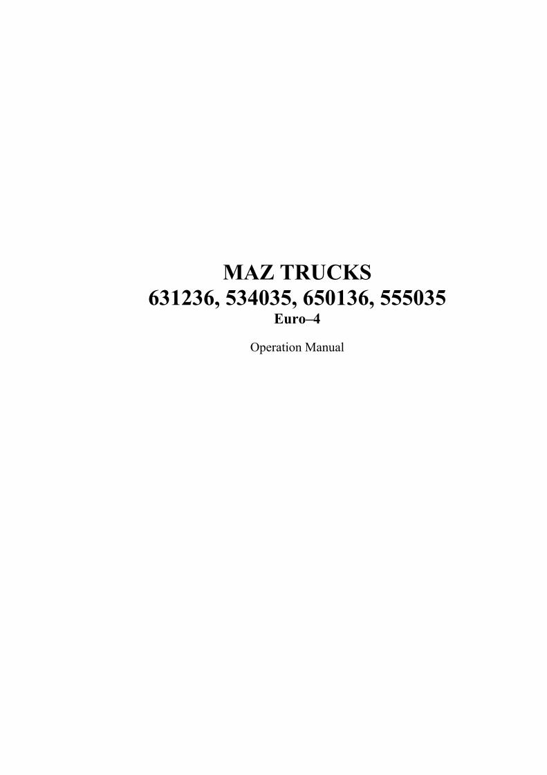
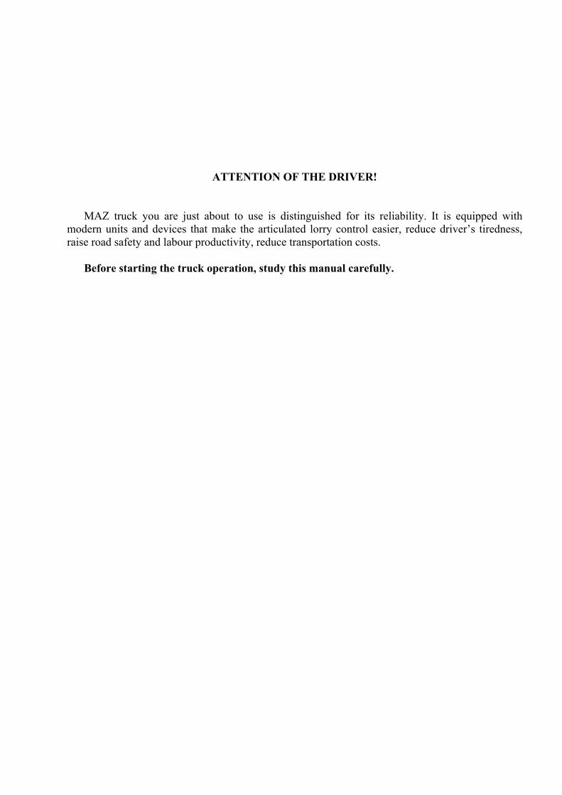
MAZ–631236 is a three-axle and MAZ–534035 is a two-axle chassis (see Figures 1, 2) that are intended for mounting of different technological equipment and use on the roads where the axial loads stated in the technical characteristics are allowed.
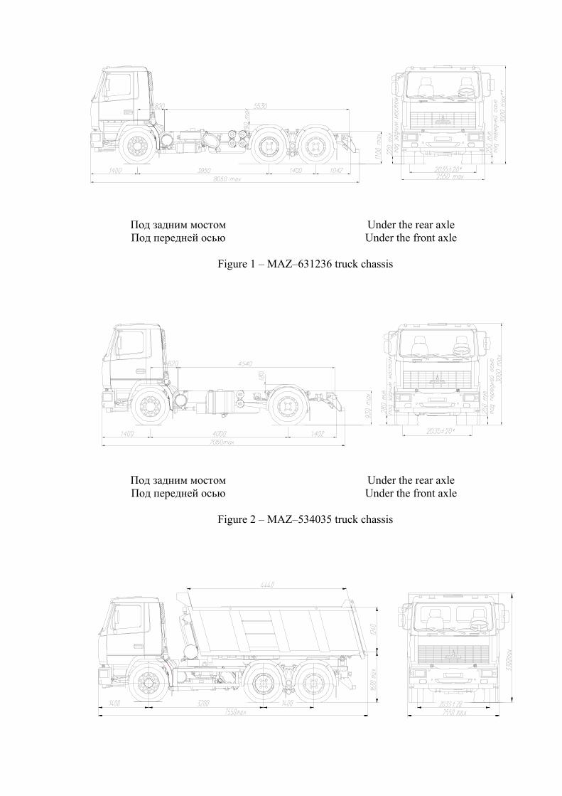
MAZ–650136 is a 6×4 three-axle dump-truck (see Figure 3) and MAZ–555035 is 4×2 two-axle dump-truck with a metal body (see Figure 4) that is dumped with the help of a hydraulic mechanism and is designed for non-metallic building, industrial and domestic bulk cargo by a single truck or within an articulated lorry on open and special roads where the axial loads stated in the technical characteristics are allowed.
The trucks are equipped with «Deutz» engines of Euro-4 ecological standard. The information on power unit operation servicing (engine, clutch, gearbox) is given in separate
manufacturer-plants manuals additionally enclosed with the truck.
Под задним мостом Under the rear axle Под передней осью Under the front axle
Figure 1 – MAZ–631236 truck chassis
Под задним мостом Under the rear axle Под передней осью Under the front axle
Figure 2 – MAZ–534035 truck chassis
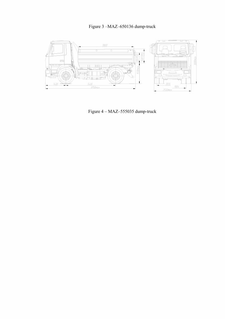
Figure 3 –MAZ–650136 dump-truck
Figure 4 – MAZ–555035 dump-truck
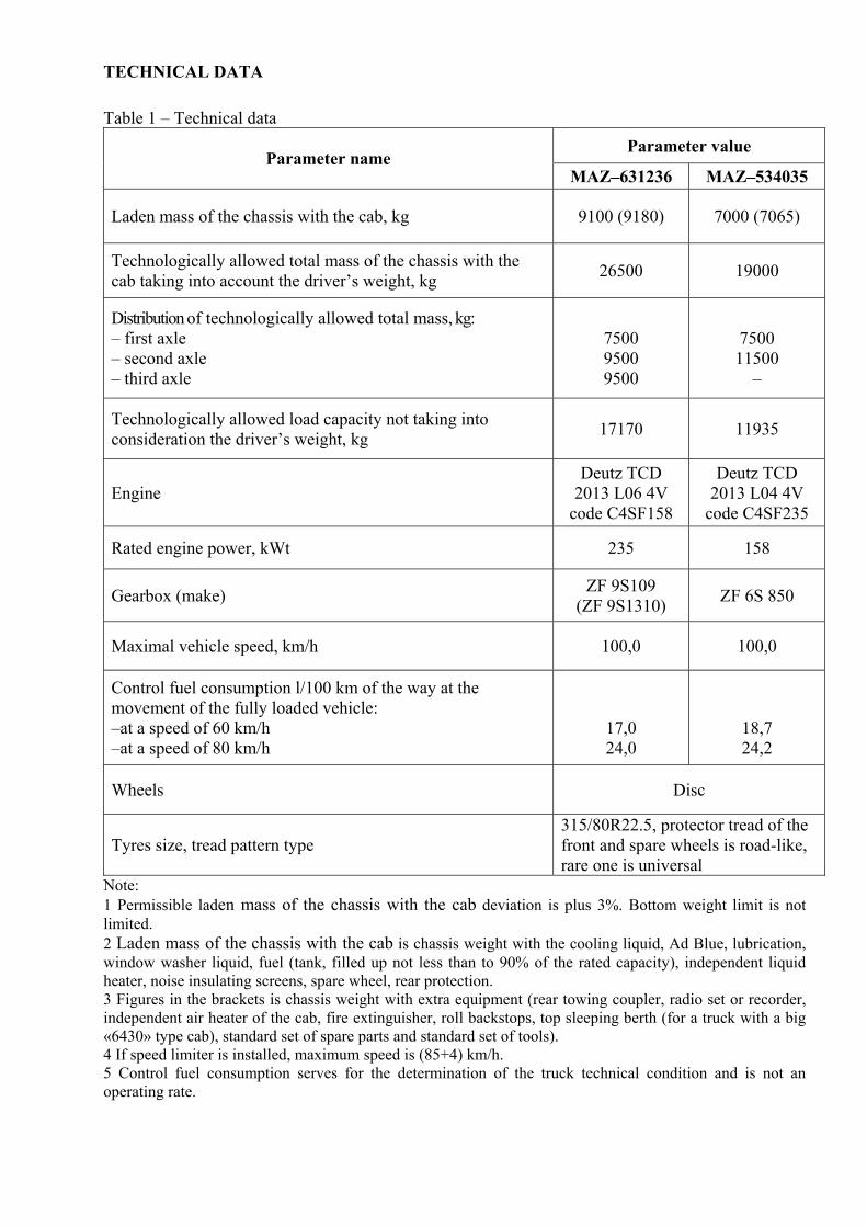
TECHNICAL DATA
Table 1 – Technical data Parameter value
Parameter name MAZ–631236 MAZ–534035
Laden mass of the chassis with the cab, kg 9100 (9180) 7000 (7065)
Technologically allowed total mass of the chassis with the cab taking into account the driver’s weight, kg 26500 19000
Distribution of technologically allowed total mass, kg: – first axle – second axle – third axle
7500 9500 9500
7500 11500
–
Technologically allowed load capacity not taking into consideration the driver’s weight, kg 17170 11935
Engine Deutz TCD
2013 L06 4V code C4SF158
Deutz TCD 2013 L04 4V
code C4SF235
Rated engine power, kWt 235 158
Gearbox (make) ZF 9S109 (ZF 9S1310) ZF 6S 850
Maximal vehicle speed, km/h 100,0 100,0
Control fuel consumption l/100 km of the way at the movement of the fully loaded vehicle: –at a speed of 60 km/h –at a speed of 80 km/h
17,0 24,0
18,7 24,2
Wheels Disc
Tyres size, tread pattern type 315/80R22.5, protector tread of the front and spare wheels is road-like, rare one is universal
Note: 1 Permissible laden mass of the chassis with the cab deviation is plus 3%. Bottom weight limit is not limited. 2 Laden mass of the chassis with the cab is chassis weight with the cooling liquid, Ad Blue, lubrication, window washer liquid, fuel (tank, filled up not less than to 90% of the rated capacity), independent liquid heater, noise insulating screens, spare wheel, rear protection. 3 Figures in the brackets is chassis weight with extra equipment (rear towing coupler, radio set or recorder, independent air heater of the cab, fire extinguisher, roll backstops, top sleeping berth (for a truck with a big «6430» type cab), standard set of spare parts and standard set of tools). 4 If speed limiter is installed, maximum speed is (85+4) km/h. 5 Control fuel consumption serves for the determination of the truck technical condition and is not an operating rate.
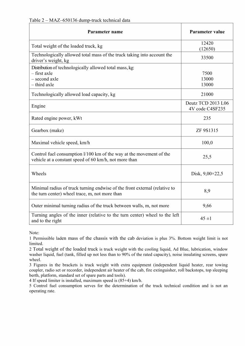
Table 2 – MAZ–650136 dump-truck technical data
Parameter name Parameter value
Total weight of the loaded truck, kg 12420 (12650)
Technologically allowed total mass of the truck taking into account the driver’s weight, kg 33500
Distribution of technologically allowed total mass, kg: – first axle – second axle – third axle
7500 13000 13000
Technologically allowed load capacity, kg 21000
Engine Deutz TCD 2013 L06 4V code C4SF235
Rated engine power, kWt 235
Gearbox (make) ZF 9S1315
Maximal vehicle speed, km/h 100,0
Control fuel consumption l/100 km of the way at the movement of the vehicle at a constant speed of 60 km/h, not more than 25,5
Wheels Disk, 9,00×22,5
Minimal radius of truck turning endwise of the front external (relative to the turn center) wheel trace, m, not more than 8,9
Outer minimal turning radius of the truck between walls, m, not more 9,66
Turning angles of the inner (relative to the turn center) wheel to the left and to the right 45 ±1
Note: 1 Permissible laden mass of the chassis with the cab deviation is plus 3%. Bottom weight limit is not limited. 2 Total weight of the loaded truck is truck weight with the cooling liquid, Ad Blue, lubrication, window washer liquid, fuel (tank, filled up not less than to 90% of the rated capacity), noise insulating screens, spare wheel. 3 Figures in the brackets is truck weight with extra equipment (independent liquid heater, rear towing coupler, radio set or recorder, independent air heater of the cab, fire extinguisher, roll backstops, top sleeping berth, platform, standard set of spare parts and tools). 4 If speed limiter is installed, maximum speed is (85+4) km/h. 5 Control fuel consumption serves for the determination of the truck technical condition and is not an operating rate.
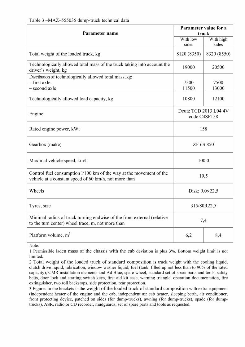
Table 3 –MAZ–555035 dump-truck technical data
Note: 1 Permissible laden mass of the chassis with the cab deviation is plus 3%. Bottom weight limit is not limited. 2 Total weight of the loaded truck of standard composition is truck weight with the cooling liquid, clutch drive liquid, lubrication, window washer liquid, fuel (tank, filled up not less than to 90% of the rated capacity), CMR installation elements and Ad Blue, spare wheel, standard set of spare parts and tools, safety belts, door lock and starting switch keys, first aid kit case, warning triangle, operation documentation, fire extinguisher, two roll backstops, side protection, rear protection. 3 Figures in the brackets is the weight of the loaded truck of standard composition with extra equipment (independent heater of the engine and the cab, independent air cab heater, sleeping berth, air conditioner, front protecting device, patched on sides (for dump-trucks), awning (for dump-trucks), spade (for dump-trucks), ASR, radio or CD recorder, mudguards, set of spare parts and tools as requested.
Parameter value for a truck Parameter name
With low sides
With high sides
Total weight of the loaded truck, kg 8120 (8350) 8320 (8550)
Technologically allowed total mass of the truck taking into account the driver’s weight, kg 19000 20500
Distribution of technologically allowed total mass, kg: – first axle – second axle
7500 11500
7500 13000
Technologically allowed load capacity, kg 10800 12100
Engine Deutz TCD 2013 L04 4V code C4SF158
Rated engine power, kWt 158
Gearbox (make) ZF 6S 850
Maximal vehicle speed, km/h 100,0
Control fuel consumption l/100 km of the way at the movement of the vehicle at a constant speed of 60 km/h, not more than 19,5
Wheels Disk; 9,0×22,5
Tyres, size 315/80R22,5
Minimal radius of truck turning endwise of the front external (relative to the turn center) wheel trace, m, not more than 7,4
Platform volume, m3 6,2 8,4
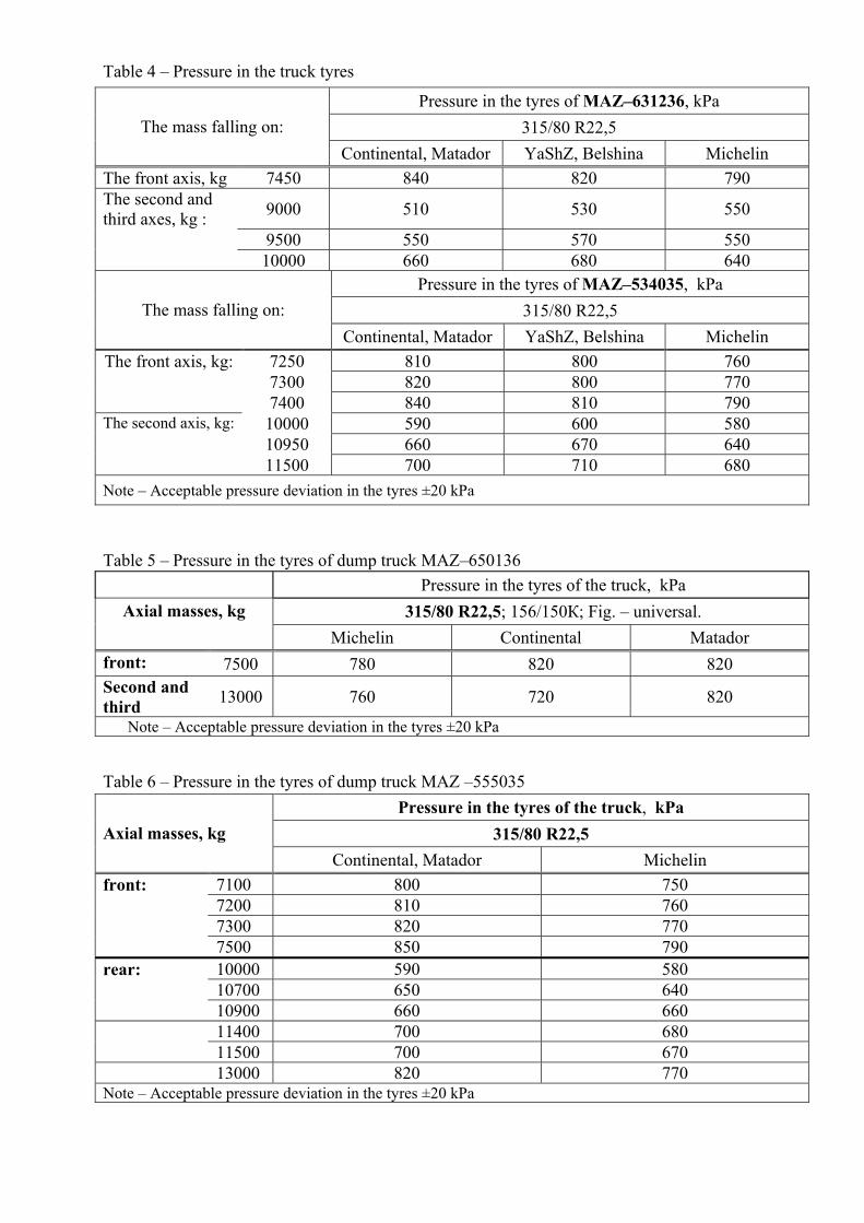
Table 4 – Pressure in the truck tyres
Table 5 – Pressure in the tyres of dump truck MAZ–650136
Table 6 – Pressure in the tyres of dump truck MAZ –555035
Pressure in the tyres of MAZ–631236, kPa 315/80 R22,5 The mass falling on:
Continental, Matador YaShZ, Belshina Michelin The front axis, kg 7450 840 820 790 The second and third axes, kg : 9000 510 530 550
9500 550 570 550 10000 660 680 640
Pressure in the tyres of MAZ–534035, kPa 315/80 R22,5 The mass falling on:
Continental, Matador YaShZ, Belshina Michelin The front axis, kg: 7250 810 800 760
7300 820 800 770 7400 840 810 790
The second axis, kg: 10000 590 600 580 10950 660 670 640 11500 700 710 680
Note – Acceptable pressure deviation in the tyres ±20 kPa
Pressure in the tyres of the truck, kPa 315/80 R22,5; 156/150К; Fig. – universal. Axial masses, kg
Michelin Continental Matador front: 7500 780 820 820 Second and third 13000 760 720 820
Note – Acceptable pressure deviation in the tyres ±20 kPa
Pressure in the tyres of the truck, kPa 315/80 R22,5 Axial masses, kg
Continental, Matador Michelin front: 7100 800 750 7200 810 760 7300 820 770 7500 850 790 rear: 10000 590 580 10700 650 640 10900 660 660 11400 700 680 11500 700 670 13000 820 770 Note – Acceptable pressure deviation in the tyres ±20 kPa
SAFETY REQUIREMENTS AND WARNINGS
Principal conditions for proper operation and reliable functioning of the vehicle are the knowledge of its units and aggregates construction, strict observation of the vehicle maintenance and care instructions.
Thus, prior to starting operating the truck, it is necessary to thoroughly study its design, instructions for operation, maintenance and care included into the present booklet, paying special attention to the “Truck Operation Peculiarities” section.
1 Claim form is given in Appendix 1. 2 During the truck running-in (first 2000 km of the run) it is necessary to strictly observe the
rules laid down in the “Truck running-in” section because its further performance greatly depends upon how properly the components will bed in during the initial period of operation.
3 Lubrication of the truck units and aggregates is to be executed in accordance with the “Lubrication chart” of this Manual. Application of contaminated or non-recommended grades of lubricants and oils is prohibited.
4 Truck movement is prohibited if the pressure in the air brake circuits is less than 490 kPa, i.e. until the warning lamps indicating a drop of air pressure in the brake circuits go out.
5 When starting the movement of a truck on a slippery road engage interaxle (6х4 trucks) and cross-axle differential blocking. After overcoming such part of the road unblock the differentials. Turn of the truck with blocked differentials is prohibited.
6 During the truck movement watch the readings of the control lamps and indicators. 7 Running downhill with stopped engine and disengaged gearbox is prohibited in order to avoid
steering booster cutoff and to exclude air replenishment of the brakes actuator receivers. 8 While running downhill avoid truck movement at the revolutions higher than allowed, i.e. the
tachometer pointer must not enter the red zone of the scale. 9 Operation of the truck with a defective or failed steering booster is prohibited. During the
truck movement the key is not to be pulled out of the starter actuator lock in order to avoid steering column blocking and engine cutoff.
10 In order to avoid steering booster pump breakdown, steering wheel is not to be kept in the extreme positions (at maximum turn of the operated wheels to the left and to the right) more than 5 sec.
11 On parking places switch off the batteries by means of batteries switch button. In case of long-term parking (more than 3 days) a jumper should be taken off the battery. It is prohibited to connect 12V electrical appliances (radio recorders, receivers etc.) to the battery.
12 It is necessary to follow the scope and periodicity of the truck maintenance, stated in this manual.
13 Power unit service works are stated in a separate manual. 14 Power unit maintenance is to be carried out on a level ground with a cab completely lifted. It is strictly forbidden to stand under the cab that is not fully lifted. 15 Cab lifting is to be carried out on an even level ground. The vehicle is to be braked by a
parking brake. Before lifting the cab the lever of the gear box must be moved to the neutral position, the doors must be closed and front facing of the cab must be opened. In is forbidden to stand in the zone of the cab tilting.
16 Lifting and lowering of the cab at the working engine is prohibited in order to avoid spontaneous engagement of the gear box and, as a result, start of unauthorized movement of the truck.
17 When washing the truck, one should avoid directing the water jet to the electrical equipment and electrical wires connections.
18 Do not check the operability of the system and electrical equipment circuits with the help of megaohmmeter or a lamp fed from a source with a voltage higher than 24V.
19 Do not cut off the wires from the generator and battery terminals while the engine is working.
20 Do not allow polarity reversal when connecting the storage batteries to the truck board system.
21 While carrying out welding operations on the truck the batteries must be disconnected and electrical wires and conduits of brake actuators must be protected from high (higher than 900С) temperatures and weld spatters.
22 Starting of the truck engine from an external source or using of the truck board system as an external source for starting of another truck are prohibited in order to avoid the breakdown of electronic control units.
23 After lowering the cab make sure that locking mechanisms are locked. 24 The polarity of the batteries is to be strictly observed in order to avoid the breakdown of the
generator: – minus (–) battery terminal through the right engine support to the truck body; – plus (+) battery terminal through the battery switch to the starter terminal (plus). 25 While mounting electrical equipment onto the truck, when carrying out the works under the
truck, on the engine with the cab lifted, while hand cranking (in case the starter drive gear teeth are stopped by the engine flywheel crown etc.), in case of emergency on the truck (short circuit, electrical wire ignition etc.) the batteries should be disconnected).
26 Engine start with the cab lifted is prohibited. In case there is a necessity to start the engine with a lifted cab for carrying out adjustments and repair works it is necessary to make sure that gear box is in neutral position. Engine starting is to be fulfilled with the observation of the «Safety rules».
27 In order to avoid untimely failure of the pressure regulator with the adsorber it is necessary to watch the airtightness of the truck pneumatic systems.
28 During the movement of the vehicles (road trains) along the roads of general use, as well as along the streets of cities and settlements the drivers should follow the requirements of the normative documents valid for the country, that will set the allowances for weight and dimensions and the rules of travel in case they are exceeded.
29 When the dump-truck platform and its trailer are loaded with bulk materials, the volume of the excavator bucket should not be bigger than 2,5m3, and the dump height above the platform floor – 1,5 m.
The load should be evenly distributed on the platform. In order to avoid platform damage and load hanging-up during the unloading, separate monolithic blocks or frozen pieces of bulk material shall not be bigger than 0,4 m and heavier than 300 kg.
30 Lifting of the loaded platform of the dump-truck with a faulty stabilizer of the transversal stability in the rear suspension is not allowed.
31 Engaging of the platform lifting hydraulic system pump at the air pressure in the system lower than 490 kPa and disengaged clutch is not allowed.
32 Unloading of the dump-truck and its trailer should be made on an even flat ground with a hard surface. In case there signs of stability loss, stop the unloading immediately.
33 Start of the dump-truck movement with the platform lifted is not allowed. 34 It is prohibited to work under the lifted loaded platform. 35 When working under the lifted unloaded platform of a dump-truck, the platform must be
locked by special locking devices (safety stops) not to let its lowering. 36 If the load is not unloading when the platform is lifted at approximately 20º the platform
lifting should be stopped and the reason investigated.
CONTROLS AND INSTRUMENTATION
The arrangement of controls and instrumentation is shown on Figures 5, 6, 7. Parking and emergency brakes drive valve handle Is located to the right from the steering column under the dashboard. The handle can be fixed
in two extreme positions. In the lower extreme fixed position parking brake is engaged, and it is disengaged when the handle is moved to the top fixed position. When keeping the handle in any intermediate (non-fixed) position, emergency brake is engaged.
When pushing the handle end in the extreme lower position and auxiliary moving downwards, unbraking of the semitrailer and the check of the road train keeping on a slope by means of truck brakes takes place.
Emergency brakes drive valve button Is located on the cab floor to the left from the driver. When the button is pressed butterfly valve creates counterpressure in the exhaust system by
blocking the flow passage in the exhaust gases manifold. At the same time fuel feed cuts off. Steering wheel with an energy-absorbing steering column and a device that allows its height
and inclination adjustment. Adjustments are carried out by pressing the pedal that is located on the steering column
fastening bracket. After placing the steering wheel into a comfortable position, release the pedal.
Starter and steering column instruments switch-lock with an antitheft device. The key is inserted and taken out of the lock in position III (Figure 5).
In order to unlock the steering column shaft it is necessary to insert the key into the switch-lock and, in order to avoid key braking, turn the steering wheel to the left – to the right a bit, and then turn the key clockwise to the position «0».
When taking the key out of the switch-lock (from position III) the lock blocking device is disabled. In order to block the steering column shaft it is necessary to turn the steering wheel to the left – to the right a bit.
Other positions of the key in the lock: 0 – neutral (fixed) position. Instruments and starter circuits are switched off, the engine is shut
down; I – instruments and consumers are powered up (fixed position); II – instruments, consumers and starter circuits are powered off (non-fixed position). Handle 3 of the windscreen wiper switch is located on the steering wheel, on the right-hand
side. There are following positions: In the horizontal plane: 0 – neutral (fixed); I (fixed) – windscreen wiper is engaged on a low speed; II (fixed) – windscreen wiper is engaged on a high speed; III (fixed) – windscreen wiper is engaged in intermitted duty regime. In the vertical plane: IV (non-fixed) – windscreen washer is engaged with a simultaneous switching on of the
windscreen wiper on a low speed. When pressing the handle end, pneumatic sound alarm is switched on at any position of the
handle. Handle 2 of the turn indicator, lower beam and upper beam switch is located on the steering
column, at the left-hand side. There are following positions: In the horizontal plane: 0 – neutral (fixed);
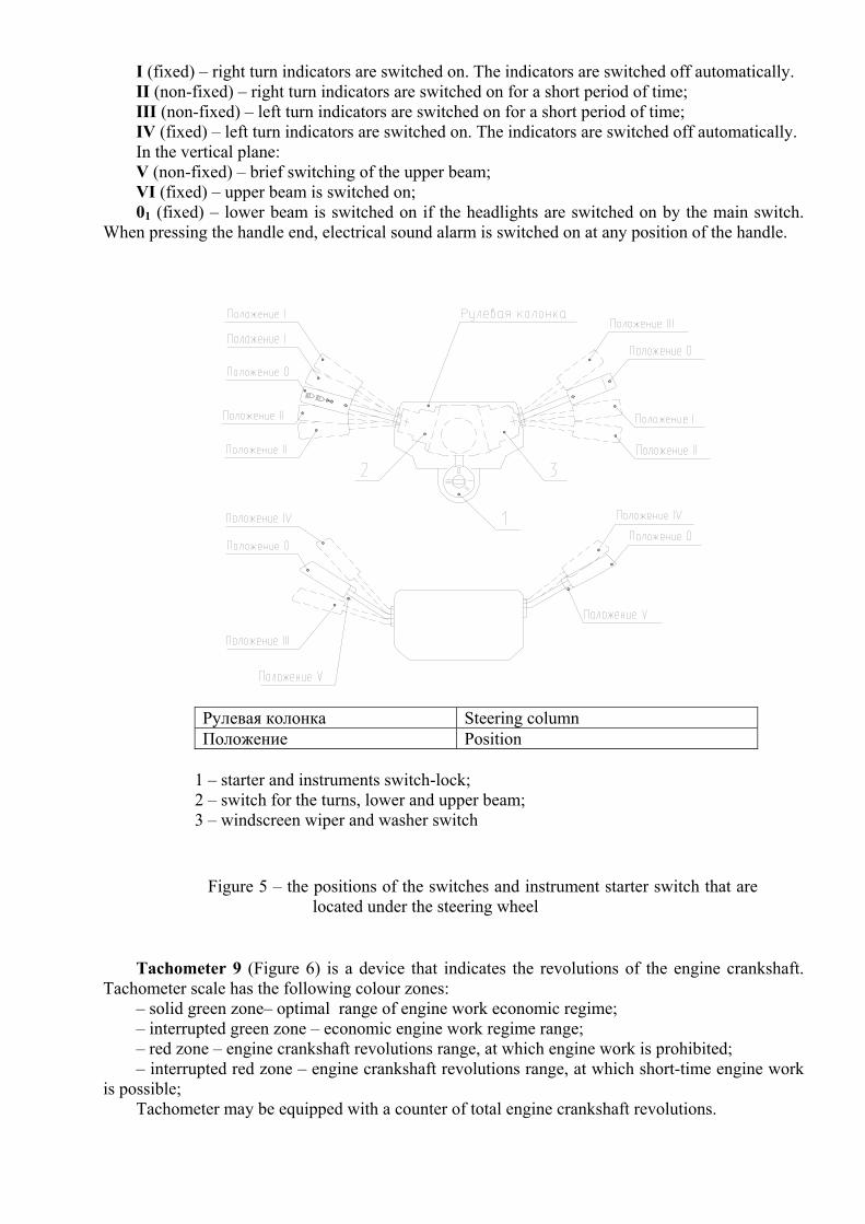
I (fixed) – right turn indicators are switched on. The indicators are switched off automatically. II (non-fixed) – right turn indicators are switched on for a short period of time; III (non-fixed) – left turn indicators are switched on for a short period of time; IV (fixed) – left turn indicators are switched on. The indicators are switched off automatically. In the vertical plane: V (non-fixed) – brief switching of the upper beam; VI (fixed) – upper beam is switched on; 01 (fixed) – lower beam is switched on if the headlights are switched on by the main switch.
When pressing the handle end, electrical sound alarm is switched on at any position of the handle.
Рулевая колонка Steering column Положение Position
1 – starter and instruments switch-lock; 2 – switch for the turns, lower and upper beam; 3 – windscreen wiper and washer switch
Figure 5 – the positions of the switches and instrument starter switch that are located under the steering wheel
Tachometer 9 (Figure 6) is a device that indicates the revolutions of the engine crankshaft. Tachometer scale has the following colour zones:
– solid green zone– optimal range of engine work economic regime; – interrupted green zone – economic engine work regime range; – red zone – engine crankshaft revolutions range, at which engine work is prohibited; – interrupted red zone – engine crankshaft revolutions range, at which short-time engine work
is possible; Tachometer may be equipped with a counter of total engine crankshaft revolutions.

Batteries switch remote control button 8. When batteries switch is turned on the voltage indicator pointer indicates the voltage of the embedded network.
The batteries are to be switched off at the parking as well as in order to disconnect energy consumers in cases of emergency.
In case the remote control doesn’t operate, the switch can be turned on or off by pressing the button on the switch case that is located on the front or rear wall of the battery container.
Tachograph 11 is a device that shows the speed, current time and the total distance passed. On
a special disc there is a recording (ciphered) of the speed, way and drivers’ (one or two) working regime.
Remote control of the independent air heater (if installed). It is dedicated for switching on/off
of the heating regime and setting of the cab temperature that is kept automatically by an independent air heater.
12040
0
20
8
32
0 1
0 10
0 10
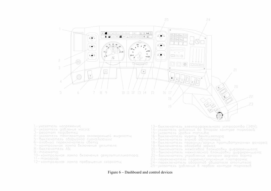
Figure 6 – Dashboard and control devices
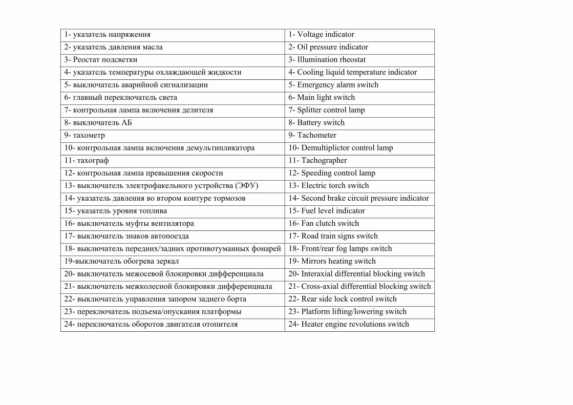
1- указатель напряжения 1- Voltage indicator 2- указатель давления масла 2- Oil pressure indicator 3- Реостат подсветки 3- Illumination rheostat 4- указатель температуры охлаждающей жидкости 4- Cooling liquid temperature indicator 5- выключатель аварийной сигнализации 5- Emergency alarm switch 6- главный переключатель света 6- Main light switch 7- контрольная лампа включения делителя 7- Splitter control lamp 8- выключатель АБ 8- Battery switch 9- тахометр 9- Tachometer 10- контрольная лампа включения демультипликатора 10- Demultiplictor control lamp 11- тахограф 11- Tachographer 12- контрольная лампа превышения скорости 12- Speeding control lamp 13- выключатель электрофакельного устройства (ЭФУ) 13- Electric torch switch 14- указатель давления во втором контуре тормозов 14- Second brake circuit pressure indicator 15- указатель уровня топлива 15- Fuel level indicator 16- выключатель муфты вентилятора 16- Fan clutch switch 17- выключатель знаков автопоезда 17- Road train signs switch 18- выключатель передних/задних противотуманных фонарей 18- Front/rear fog lamps switch 19-выключатель обогрева зеркал 19- Mirrors heating switch 20- выключатель межосевой блокировки дифференциала 20- Interaxial differential blocking switch 21- выключатель межколесной блокировки дифференциала 21- Cross-axial differential blocking switch22- выключатель управления запором заднего борта 22- Rear side lock control switch 23- переключатель подъема/опускания платформы 23- Platform lifting/lowering switch 24- переключатель оборотов двигателя отопителя 24- Heater engine revolutions switch
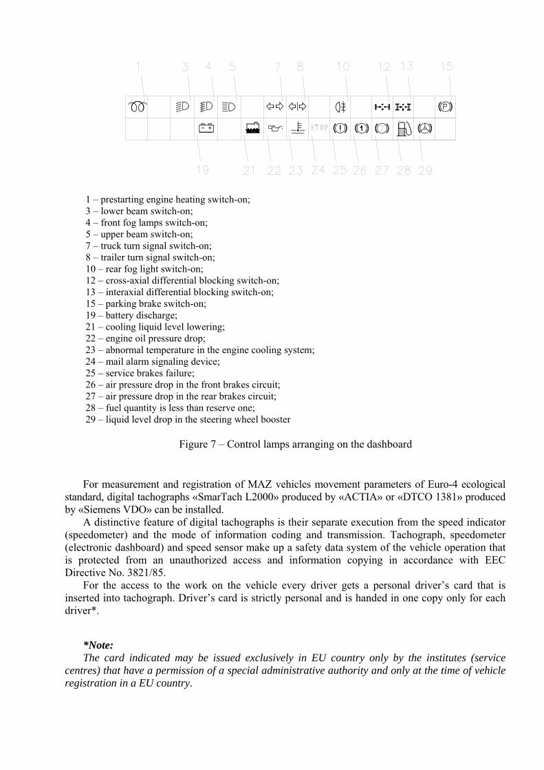
1 – prestarting engine heating switch-on; 3 – lower beam switch-on; 4 – front fog lamps switch-on; 5 – upper beam switch-on; 7 – truck turn signal switch-on; 8 – trailer turn signal switch-on; 10 – rear fog light switch-on; 12 – cross-axial differential blocking switch-on; 13 – interaxial differential blocking switch-on; 15 – parking brake switch-on; 19 – battery discharge; 21 – cooling liquid level lowering; 22 – engine oil pressure drop; 23 – abnormal temperature in the engine cooling system; 24 – mail alarm signaling device; 25 – service brakes failure; 26 – air pressure drop in the front brakes circuit; 27 – air pressure drop in the rear brakes circuit; 28 – fuel quantity is less than reserve one; 29 – liquid level drop in the steering wheel booster
Figure 7 – Control lamps arranging on the dashboard
For measurement and registration of MAZ vehicles movement parameters of Euro-4 ecological standard, digital tachographs «SmarTach L2000» produced by «ACTIA» or «DTCO 1381» produced by «Siemens VDO» can be installed.
A distinctive feature of digital tachographs is their separate execution from the speed indicator (speedometer) and the mode of information coding and transmission. Tachograph, speedometer (electronic dashboard) and speed sensor make up a safety data system of the vehicle operation that is protected from an unauthorized access and information copying in accordance with EEC Directive No. 3821/85.
For the access to the work on the vehicle every driver gets a personal driver’s card that is inserted into tachograph. Driver’s card is strictly personal and is handed in one copy only for each driver*.
*Note: The card indicated may be issued exclusively in EU country only by the institutes (service
centres) that have a permission of a special administrative authority and only at the time of vehicle registration in a EU country.
The information on the vehicle speed, regimes of its work and the regimes of the driver(s)’s work and rest is registered in the electronic memory of the tachograph, later on the information can be read out, printed out and checked by supervisory bodies. Recording and readout of the information is performed in such way as to check its integrity and authenticity in the future.
In accordance with EU Directive No. 3821/85, periodical inspection of digital techographs should be carried out at any condition of the device, at least once every two years after the last check.
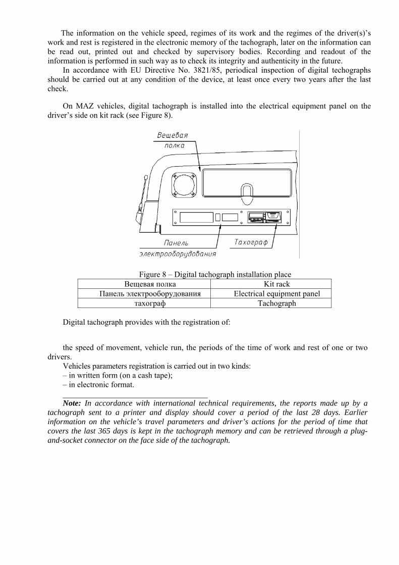
On MAZ vehicles, digital tachograph is installed into the electrical equipment panel on the driver’s side on kit rack (see Figure 8).
Figure 8 – Digital tachograph installation place Вещевая полка Kit rack
Панель электрооборудования Electrical equipment panel тахограф Tachograph
Digital tachograph provides with the registration of:
the speed of movement, vehicle run, the periods of the time of work and rest of one or two drivers.
Vehicles parameters registration is carried out in two kinds: – in written form (on a cash tape); – in electronic format. ____________________________________ Note: In accordance with international technical requirements, the reports made up by a
tachograph sent to a printer and display should cover a period of the last 28 days. Earlier information on the vehicle’s travel parameters and driver’s actions for the period of time that covers the last 365 days is kept in the tachograph memory and can be retrieved through a plug-and-socket connector on the face side of the tachograph.
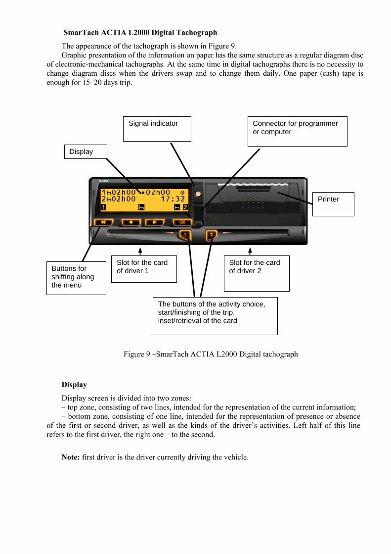
SmarTach ACTIA L2000 Digital Tachograph
The appearance of the tachograph is shown in Figure 9. Graphic presentation of the information on paper has the same structure as a regular diagram disc
of electronic-mechanical tachographs. At the same time in digital tachographs there is no necessity to change diagram discs when the drivers swap and to change them daily. One paper (cash) tape is enough for 15–20 days trip.
Figure 9 –SmarTach ACTIA L2000 Digital tachograph
Display
Display screen is divided into two zones: – top zone, consisting of two lines, intended for the representation of the current information; – bottom zone, consisting of one line, intended for the representation of presence or absence
of the first or second driver, as well as the kinds of the driver’s activities. Left half of this line refers to the first driver, the right one – to the second.
Note: first driver is the driver currently driving the vehicle.
Connector for programmer or computer
Signal indicator
Display
Printer
Buttons for shifting along the menu
The buttons of the activity choice, start/finishing of the trip, inset/retrieval of the card
Slot for the card of driver 1
Slot for the card of driver 2
Meaning of different pictograms in the bottom line:
– presence of the first driver;
– presence of the second driver;
– «driving»– current activity of the first driver during the run (this pictogram is displayed only on the left side of the line, in the zone of the first driver);
– «work»– current activity of the first driver (left side) or the second (right side);
·–«readiness»– current activity of the first driver (left side) or the second (right side);
–«rest»– current activity of the first driver (left side) or the second (right side);
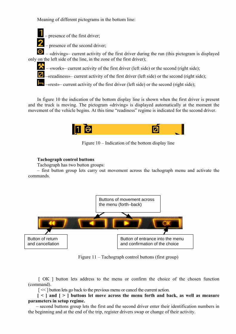
In figure 10 the indication of the bottom display line is shown when the first driver is present and the truck is moving. The pictogram «driving» is displayed automatically at the moment the movement of the vehicle begins. At this time “readiness” regime is indicated for the second driver.
Figure 10 – Indication of the bottom display line
Tachograph control buttons Tachograph has two button groups: – first button group lets carry out movement across the tachograph menu and activate the
commands.
Figure 11 – Tachograph control buttons (first group)
[ ОК ] button lets address to the menu or confirm the choice of the chosen function
(command). [ << ] button lets go back to the previous menu or cancel the current action. [ < ] and [ > ] buttons let move across the menu forth and back, as well as measure
parameters in setup regime. – second buttons group lets the first and the second driver enter their identification numbers in
the beginning and at the end of the trip, register drivers swap or change of their activity.
Buttons of movement across the menu (forth–back)
Button of return and cancellation
Button of entrance into the menu and confirmation of the choice
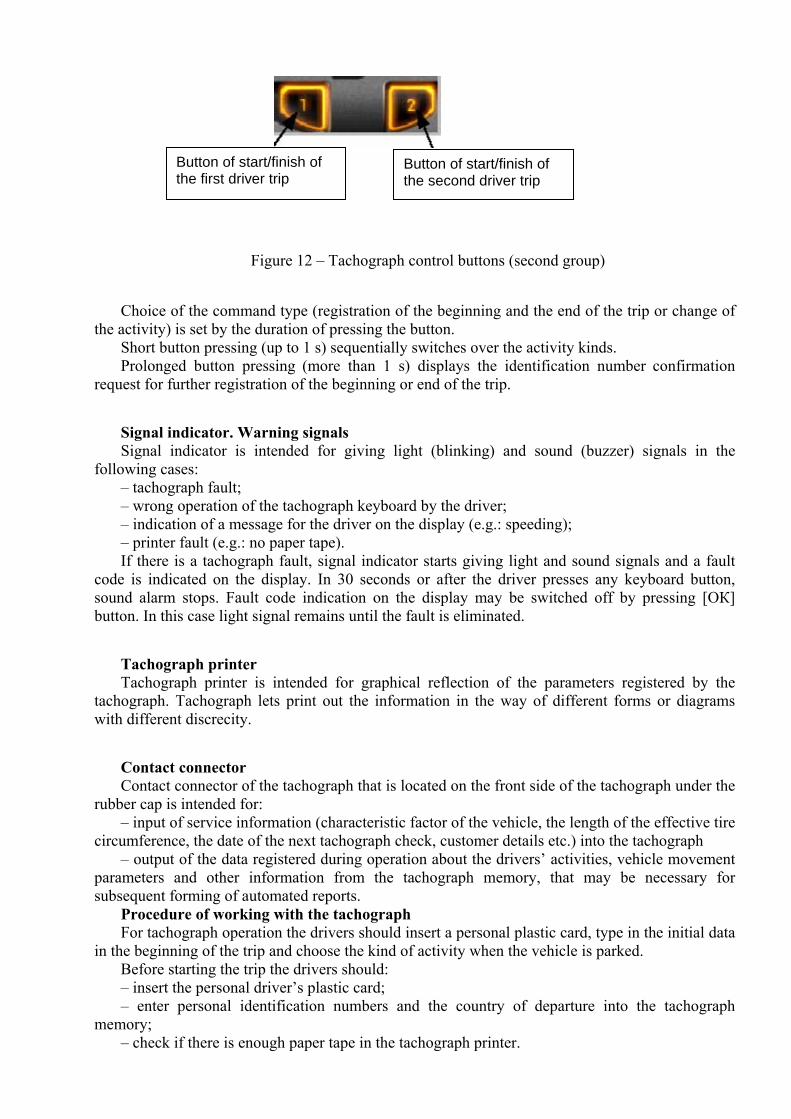
Figure 12 – Tachograph control buttons (second group)
Choice of the command type (registration of the beginning and the end of the trip or change of the activity) is set by the duration of pressing the button.
Short button pressing (up to 1 s) sequentially switches over the activity kinds. Prolonged button pressing (more than 1 s) displays the identification number confirmation
request for further registration of the beginning or end of the trip.
Signal indicator. Warning signals Signal indicator is intended for giving light (blinking) and sound (buzzer) signals in the
following cases: – tachograph fault; – wrong operation of the tachograph keyboard by the driver; – indication of a message for the driver on the display (e.g.: speeding); – printer fault (e.g.: no paper tape). If there is a tachograph fault, signal indicator starts giving light and sound signals and a fault
code is indicated on the display. In 30 seconds or after the driver presses any keyboard button, sound alarm stops. Fault code indication on the display may be switched off by pressing [ОК] button. In this case light signal remains until the fault is eliminated.
Tachograph printer Tachograph printer is intended for graphical reflection of the parameters registered by the
tachograph. Tachograph lets print out the information in the way of different forms or diagrams with different discrecity.
Contact connector Contact connector of the tachograph that is located on the front side of the tachograph under the
rubber cap is intended for: – input of service information (characteristic factor of the vehicle, the length of the effective tire
circumference, the date of the next tachograph check, customer details etc.) into the tachograph – output of the data registered during operation about the drivers’ activities, vehicle movement
parameters and other information from the tachograph memory, that may be necessary for subsequent forming of automated reports.
Procedure of working with the tachograph For tachograph operation the drivers should insert a personal plastic card, type in the initial data
in the beginning of the trip and choose the kind of activity when the vehicle is parked. Before starting the trip the drivers should: – insert the personal driver’s plastic card; – enter personal identification numbers and the country of departure into the tachograph
memory; – check if there is enough paper tape in the tachograph printer.
Button of start/finish of the first driver trip
Button of start/finish of the second driver trip
When the trip is over the drivers should confirm their personal identification number and put in the country of entrance into the tachograph memory.
All the actions should be cariied out in accordance with the particular tachograph operation manual that is enclosed with the vehicle at the time of the tachograph installation.
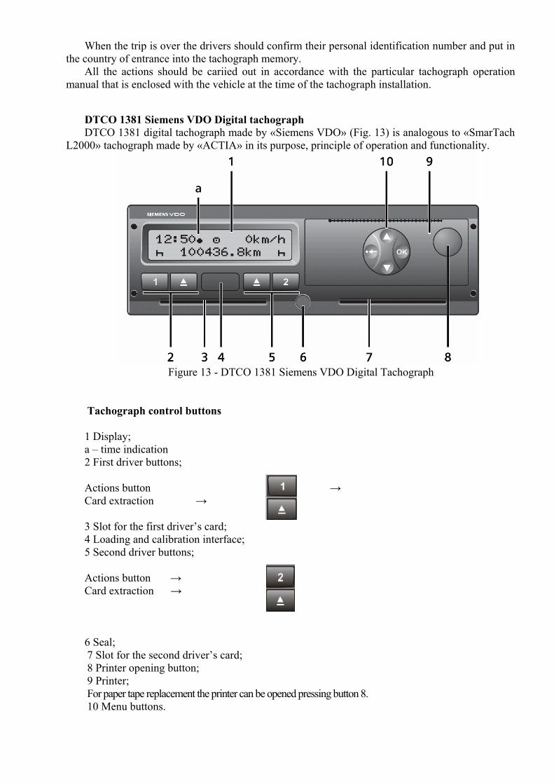
DTCO 1381 Siemens VDO Digital tachograph DTCO 1381 digital tachograph made by «Siemens VDO» (Fig. 13) is analogous to «SmarTach
L2000» tachograph made by «ACTIA» in its purpose, principle of operation and functionality.
Figure 13 - DTCO 1381 Siemens VDO Digital Tachograph
Tachograph control buttons 1 Display; а – time indication 2 First driver buttons; Actions button → Card extraction → 3 Slot for the first driver’s card; 4 Loading and calibration interface; 5 Second driver buttons; Actions button → Card extraction → 6 Seal; 7 Slot for the second driver’s card; 8 Printer opening button; 9 Printer; For paper tape replacement the printer can be opened pressing button 8. 10 Menu buttons.
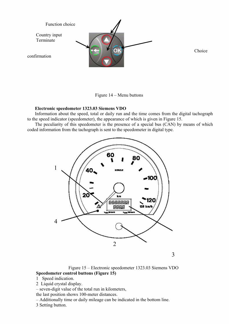
Function choice
Country input Terminate
Choice confirmation
Figure 14 – Menu buttons
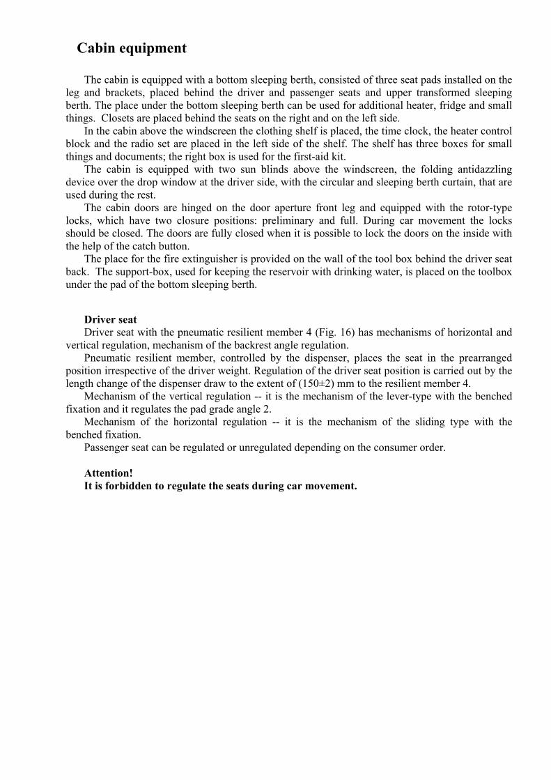
Electronic speedometer 1323.03 Siemens VDO Information about the speed, total or daily run and the time comes from the digital tachograph
to the speed indicator (speedometer), the appearance of which is given in Figure 15. The peculiarity of this speedometer is the presence of a special bus (CAN) by means of which
coded information from the tachograph is sent to the speedometer in digital type.
1
4
2
3
Figure 15 – Electronic speedometer 1323.03 Siemens VDO Speedometer control buttons (Figure 15) 1 Speed indication. 2 Liquid crystal display. – seven-digit value of the total run in kilometers, the last position shows 100-meter distances. – Additionally time or daily mileage can be indicated in the bottom line. 3 Setting button.

– short pressing – switching between the daily mileage and the time. – pressing the button longer than for two seconds in the position of daily mileage, the value of
the counter is reset to «0». 4 Operative condition check
Light indicator goes on when failures appear in one of the tachograph system components.
Cabin equipment
The cabin is equipped with a bottom sleeping berth, consisted of three seat pads installed on the leg and brackets, placed behind the driver and passenger seats and upper transformed sleeping berth. The place under the bottom sleeping berth can be used for additional heater, fridge and small things. Closets are placed behind the seats on the right and on the left side.
In the cabin above the windscreen the clothing shelf is placed, the time clock, the heater control block and the radio set are placed in the left side of the shelf. The shelf has three boxes for small things and documents; the right box is used for the first-aid kit.
The cabin is equipped with two sun blinds above the windscreen, the folding antidazzling device over the drop window at the driver side, with the circular and sleeping berth curtain, that are used during the rest.
The cabin doors are hinged on the door aperture front leg and equipped with the rotor-type locks, which have two closure positions: preliminary and full. During car movement the locks should be closed. The doors are fully closed when it is possible to lock the doors on the inside with the help of the catch button.
The place for the fire extinguisher is provided on the wall of the tool box behind the driver seat back. The support-box, used for keeping the reservoir with drinking water, is placed on the toolbox under the pad of the bottom sleeping berth.
Driver seat Driver seat with the pneumatic resilient member 4 (Fig. 16) has mechanisms of horizontal and
vertical regulation, mechanism of the backrest angle regulation. Pneumatic resilient member, controlled by the dispenser, places the seat in the prearranged
position irrespective of the driver weight. Regulation of the driver seat position is carried out by the length change of the dispenser draw to the extent of (150±2) mm to the resilient member 4.
Mechanism of the vertical regulation -- it is the mechanism of the lever-type with the benched fixation and it regulates the pad grade angle 2.
Mechanism of the horizontal regulation -- it is the mechanism of the sliding type with the benched fixation.
Passenger seat can be regulated or unregulated depending on the consumer order. Attention! It is forbidden to regulate the seats during car movement.
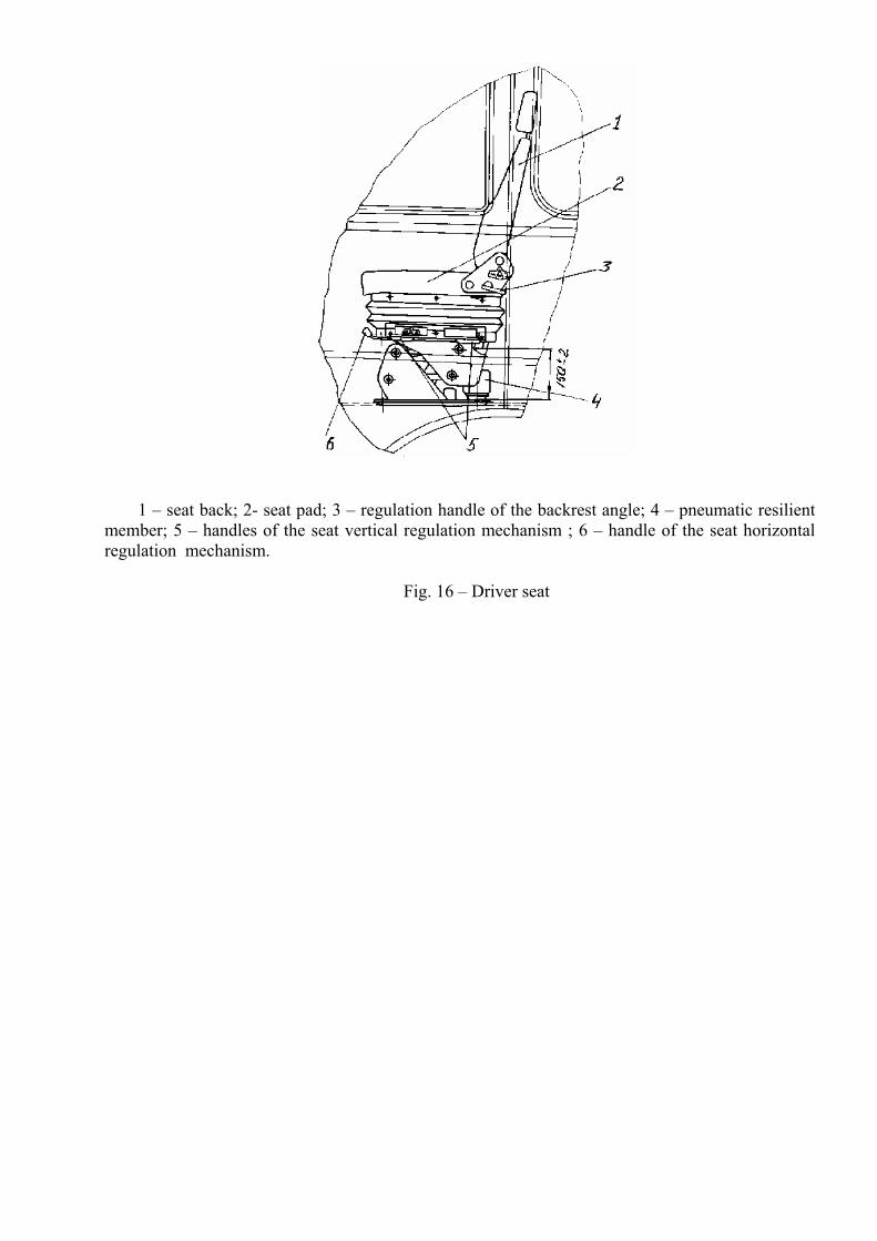
1 – seat back; 2- seat pad; 3 – regulation handle of the backrest angle; 4 – pneumatic resilient
member; 5 – handles of the seat vertical regulation mechanism ; 6 – handle of the seat horizontal regulation mechanism.
Fig. 16 – Driver seat
Job list of the presales preparation
1 Brining back into service (disposal of the antirust compound). 2 It is necessary to make sure that the product doesn’t have any damages it is necessary to
check the accessories, the instruments, the instructions in accordance with the packing list. 3 It is necessary to remand demounted for handling time articles and accessories. 4 It is necessary to check the oil presence and level in the aggregates and products units, and
add some if necessary. 5 It is necessary to add cooling liquid. 6 It is necessary to check the state of the accumulator batteries, their fastening (add
electrolyte, recharge and fix in case of need) 7 It is necessary to check good work conditions of the air brakes, clutch drive, electric
accessories, signals, cabin dumping system, tire pressure, wheel fastening and of the other links. 8 It is necessary to check good work conditions of the aggregates, of the products systems and
to eliminate damages in case of need. 9 It is necessary to check the work of the steering gear when the engine is running and to
eliminate damages in case of need. 10 It is necessary to check the product at the bottom (the absence of the cooling liquid, oil and
fuel leak and junction reliability). 11 It is necessary to clean the product and refresh the paint. 12 It is necessary to give instructions to the holder, driver.
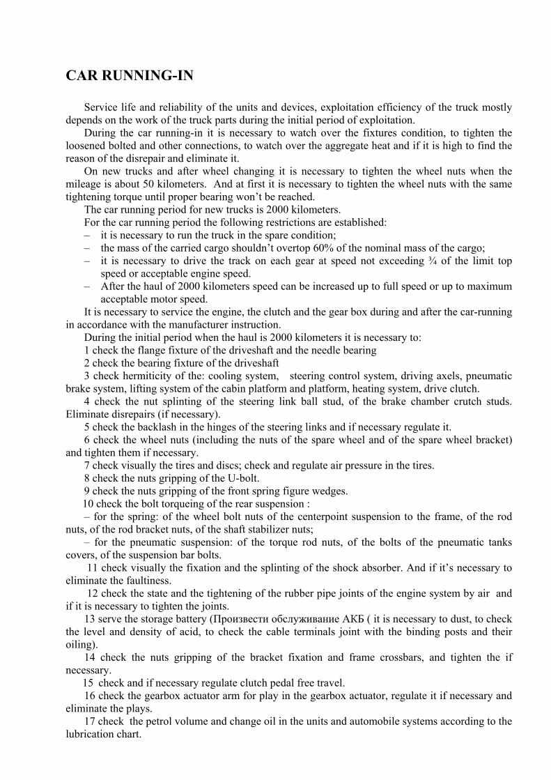
CAR RUNNING-IN
Service life and reliability of the units and devices, exploitation efficiency of the truck mostly depends on the work of the truck parts during the initial period of exploitation.
During the car running-in it is necessary to watch over the fixtures condition, to tighten the loosened bolted and other connections, to watch over the aggregate heat and if it is high to find the reason of the disrepair and eliminate it.
On new trucks and after wheel changing it is necessary to tighten the wheel nuts when the mileage is about 50 kilometers. And at first it is necessary to tighten the wheel nuts with the same tightening torque until proper bearing won’t be reached.
The car running period for new trucks is 2000 kilometers. For the car running period the following restrictions are established: – it is necessary to run the truck in the spare condition; – the mass of the carried cargo shouldn’t overtop 60% of the nominal mass of the cargo; – it is necessary to drive the track on each gear at speed not exceeding ¾ of the limit top
speed or acceptable engine speed. – After the haul of 2000 kilometers speed can be increased up to full speed or up to maximum
acceptable motor speed. It is necessary to service the engine, the clutch and the gear box during and after the car-running
in accordance with the manufacturer instruction. During the initial period when the haul is 2000 kilometers it is necessary to: 1 check the flange fixture of the driveshaft and the needle bearing 2 check the bearing fixture of the driveshaft 3 check hermiticity of the: cooling system, steering control system, driving axels, pneumatic
brake system, lifting system of the cabin platform and platform, heating system, drive clutch. 4 check the nut splinting of the steering link ball stud, of the brake chamber crutch studs.
Eliminate disrepairs (if necessary). 5 check the backlash in the hinges of the steering links and if necessary regulate it. 6 check the wheel nuts (including the nuts of the spare wheel and of the spare wheel bracket)
and tighten them if necessary. 7 check visually the tires and discs; check and regulate air pressure in the tires. 8 check the nuts gripping of the U-bolt. 9 check the nuts gripping of the front spring figure wedges.
10 check the bolt torqueing of the rear suspension : – for the spring: of the wheel bolt nuts of the centerpoint suspension to the frame, of the rod
nuts, of the rod bracket nuts, of the shaft stabilizer nuts; – for the pneumatic suspension: of the torque rod nuts, of the bolts of the pneumatic tanks
covers, of the suspension bar bolts. 11 check visually the fixation and the splinting of the shock absorber. And if it’s necessary to
eliminate the faultiness. 12 check the state and the tightening of the rubber pipe joints of the engine system by air and
if it is necessary to tighten the joints. 13 serve the storage battery (Произвести обслуживание АКБ ( it is necessary to dust, to check
the level and density of acid, to check the cable terminals joint with the binding posts and their oiling).
14 check the nuts gripping of the bracket fixation and frame crossbars, and tighten the if necessary. 15 check and if necessary regulate clutch pedal free travel.
16 check the gearbox actuator arm for play in the gearbox actuator, regulate it if necessary and eliminate the plays.
17 check the petrol volume and change oil in the units and automobile systems according to the lubrication chart.
Peculiarities of Vehicle Operation
Automobile preparation for work Before starting the work it is recommended to do preparatory work, that is connected with the
car control and filling up by the maintenance material. In addition it is necessary to check: – cooling fluid availability and it’s level in the surge tank and if necessary add it; – oil level in the engine pan, in the gearbox, in the driving axels, in the steering booster
system and if it’s necessary add oil up to needed level; – the belts tension of the water pump drive, of the generator, of the compressor and steering
pump; – air pressure in the tires.
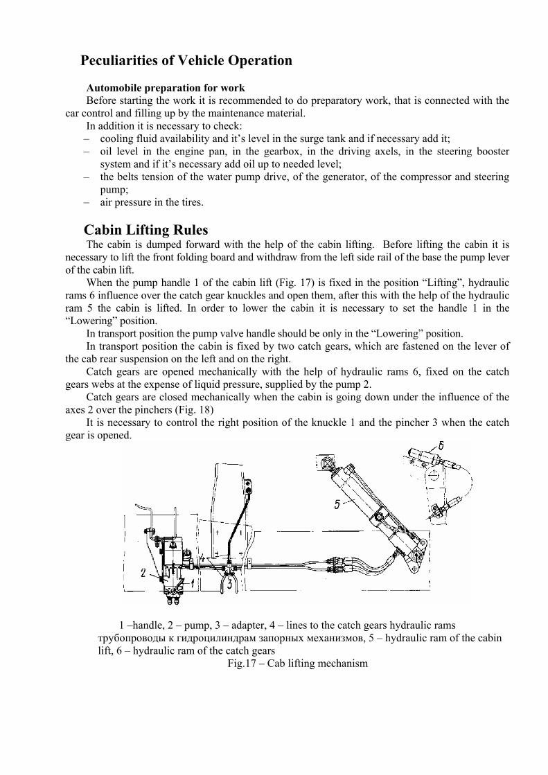
Cabin Lifting Rules The cabin is dumped forward with the help of the cabin lifting. Before lifting the cabin it is
necessary to lift the front folding board and withdraw from the left side rail of the base the pump lever of the cabin lift.
When the pump handle 1 of the cabin lift (Fig. 17) is fixed in the position “Lifting”, hydraulic rams 6 influence over the catch gear knuckles and open them, after this with the help of the hydraulic ram 5 the cabin is lifted. In order to lower the cabin it is necessary to set the handle 1 in the “Lowering” position.
In transport position the pump valve handle should be only in the “Lowering” position. In transport position the cabin is fixed by two catch gears, which are fastened on the lever of
the cab rear suspension on the left and on the right. Catch gears are opened mechanically with the help of hydraulic rams 6, fixed on the catch
gears webs at the expense of liquid pressure, supplied by the pump 2. Catch gears are closed mechanically when the cabin is going down under the influence of the
axes 2 over the pinchers (Fig. 18) It is necessary to control the right position of the knuckle 1 and the pincher 3 when the catch
gear is opened.
1 –handle, 2 – pump, 3 – adapter, 4 – lines to the catch gears hydraulic rams трубопроводы к гидроцилиндрам запорных механизмов, 5 – hydraulic ram of the cabin lift, 6 – hydraulic ram of the catch gears
Fig.17 – Cab lifting mechanism
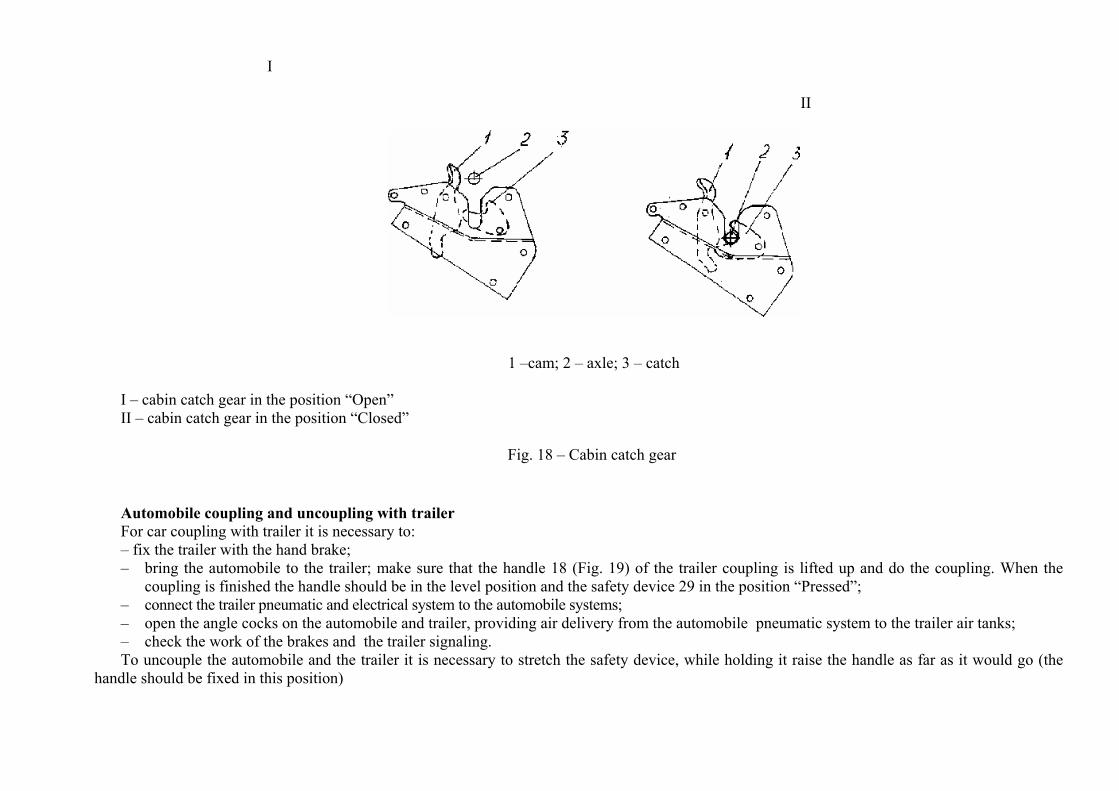
I II
1 –cam; 2 – axle; 3 – catch
I – cabin catch gear in the position “Open” II – cabin catch gear in the position “Closed”
Fig. 18 – Cabin catch gear
Automobile coupling and uncoupling with trailer For car coupling with trailer it is necessary to: – fix the trailer with the hand brake; – bring the automobile to the trailer; make sure that the handle 18 (Fig. 19) of the trailer coupling is lifted up and do the coupling. When the
coupling is finished the handle should be in the level position and the safety device 29 in the position “Pressed”; – connect the trailer pneumatic and electrical system to the automobile systems; – open the angle cocks on the automobile and trailer, providing air delivery from the automobile pneumatic system to the trailer air tanks; – check the work of the brakes and the trailer signaling. To uncouple the automobile and the trailer it is necessary to stretch the safety device, while holding it raise the handle as far as it would go (the
handle should be fixed in this position)
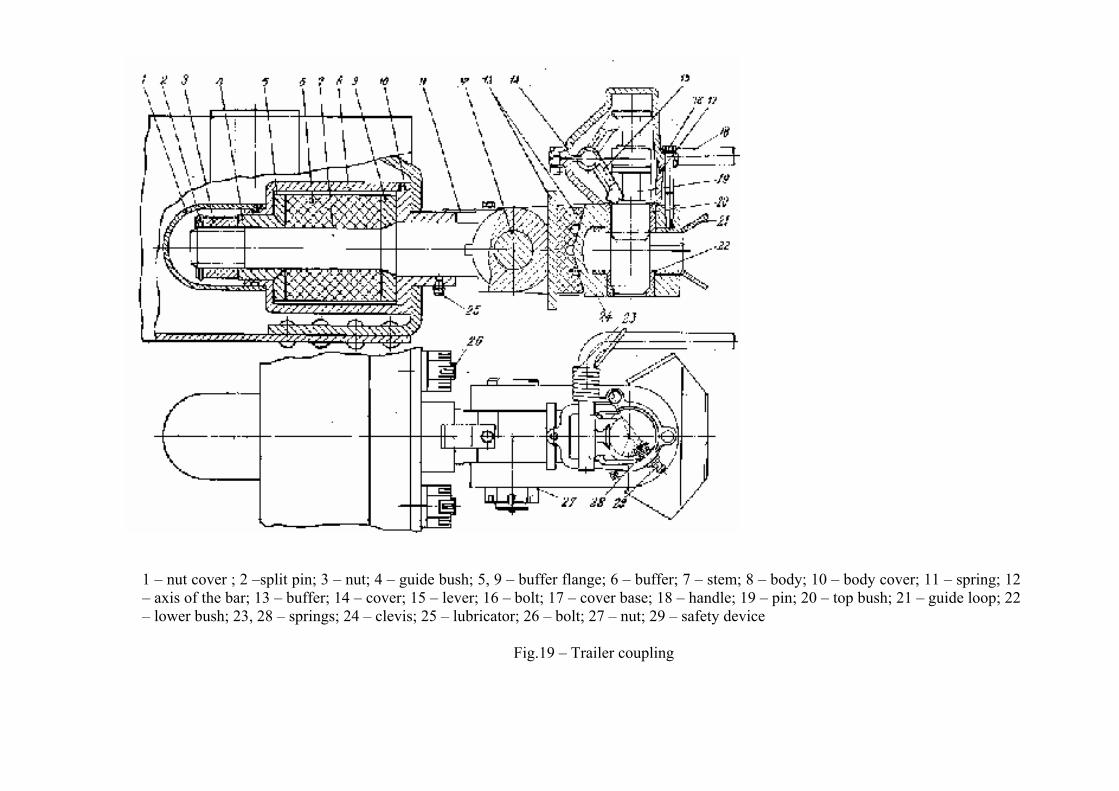
1 – nut cover ; 2 –split pin; 3 – nut; 4 – guide bush; 5, 9 – buffer flange; 6 – buffer; 7 – stem; 8 – body; 10 – body cover; 11 – spring; 12 – axis of the bar; 13 – buffer; 14 – cover; 15 – lever; 16 – bolt; 17 – cover base; 18 – handle; 19 – pin; 20 – top bush; 21 – guide loop; 22 – lower bush; 23, 28 – springs; 24 – clevis; 25 – lubricator; 26 – bolt; 27 – nut; 29 – safety device
Fig.19 – Trailer coupling
Automobile driving and control
General guidance of the automobile driving and the rules of its towing Automobile driving doesn’t have any problems on good roads. When the automobile takes off and moves on a slippery length of the road it is recommended to switch for a short-term the block system of the
interbridge and interwheel differential. The block system should be switched on just before a slippery length of the road. In this case it is necessary to switch off the clutch and switch on the block system after the automobile stop.
It is forbidden to switch on the block system of the differentials when the wheels are slipping. During winter operation and on the slippery roads poor oiling of the hooking device base plate results in bad turning over. During cargo and containers transportation with the high center of gravity the traverse speed should be chosen under the condition that lateral
stability will be ensured. In order to improve vision when it is misty or rainy it’s necessary to use fog-light. MAZ automobiles have separate contours of the brake gears pneumatic drive of the front and rear wheels, contours of the auxiliary, parking and
emergency brake. It is forbidden to move when control lamps 26, 27 (Fig. 7) are alight, signaling about inadequate pressure in the contours of the brake pneumatic drive.
In order to slow down a train along the downgrade it is necessary to use the auxiliary brake. Also it is necessary to take into account that the maximal effectiveness of the auxiliary brake is reached when the reducing gear in the gearbox is switched.
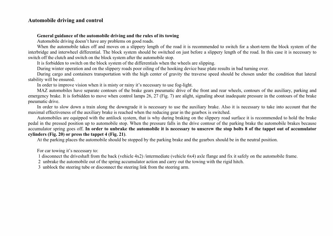
Automobiles are equipped with the antilock system, that is why during braking on the slippery road surface it is recommended to hold the brake pedal in the pressed position up to automobile stop. When the pressure falls in the drive contour of the parking brake the automobile brakes because accumulator spring goes off. In order to unbrake the automobile it is necessary to unscrew the stop bolts 8 of the tappet out of accumulator cylinders (Fig. 20) or press the tappet 4 (Fig. 21).
At the parking places the automobile should be stopped by the parking brake and the gearbox should be in the neutral position. For car towing it’s necessary to: 1 disconnect the driveshaft from the back (vehicle 4х2) /intermediate (vehicle 6х4) axle flange and fix it safely on the automobile frame. 2 unbrake the automobile out of the spring accumulator action and carry out the towing with the rigid hitch. 3 unblock the steering tube or disconnect the steering link from the steering arm.
Fig. 20 – Unscrewing of the accumulator tappet stop bolt
ELECTRONIC SYSTEM OF ENGINE CONTROL AND NEUTRALIZATION OF EXHAUST GASES The electronic systems have the installed self-diagnostic system and don’t need any technical service but the general check after their repair and control or after the repair and adjustment of the units connected with them. Purpose and structure of the electronic system of the engines Deutz (Euro 4) The engine has the electronic system of fuel delivery (EDC) of Common Rail type, which is used for controlling the dose and lead angle of the injected fuel. Additionally, in order to ensure the ecological level, the neutralization system of exhausted gases (SCR–Selective Catalytic Reduction) with the AdBlue injection is fixed on the truck. Arrangement of the system elements on the chassis is shown in the Fig. 22 (a, b), the arrangement of the elements on the relay board and safety device, the placing of electronic blocks and signaling indicators (lamps) -- in the Fig. 23. Electrical schemes are shown in the Fig. 24, 25 and 26. Possible defects and their remedies are shown in the Fig. 7. Electronic module 6 of the engine (Fig, 22) is connected with the accelerator -pedal position (13), with the switch (TSET), and also with the indicators of the cover devices and lamps (signaling indicators) through the front-end electronic block 1 or block VECU of the truck, fixed in the cabin, which forms the CAN bus of the data transmission together with the block of the engine. Information about speed of the truck is delivered from the terminal B7 of the tachograph 2 to the block VECU and goes through the CAN bus to the electronic block 6 of the engine. In the capacity of the sensor which shows the working state of the motor brake the electrical switch VKP –2 (item 14, Fig. 22) is used and it is activated by driver’s left leg. Maintenance of rules and safety standards when running the truck with the electronic system UPS and SCR.
1. Before starting the engine, visually control the lamps on the equipment board, make sure that battery is joined safely and that all systems are in good conditions.
2. It is categorically forbidden to turn the key of the switch lightning in the position «switched off» during running the truck. 3. Exploitation of the radiotelephones and transmitters, which antenna is inside the truck, can lead to failures of the electronic system and to
disturbance of safe exploitation of the truck. 4. It is forbidden to disengage the battery while engine is running. 5. It is necessary to avoid polarity changing of the battery. 6. Signal lamp of the battery charge mustn’t be alight on the working engine. 7. It is forbidden to use charging station and starting facility for launching of the engine.
8. It is necessary to detach the battery by accelerated charging. 9. It is necessary to take off the electronic block when the temperature is above 90 C. 10. It is allowed to detach the connectors of the electronic control blocks when the lock of the starter and equipment activation is switched off. 11. It is allowed to service and repair the systems at the specialized technical service station. 12. It is allowed to do welding works in the following conditions:
• the wires must be disconnected from the battery and joined together • the welding must be held by constant current when polarities are kept • the main switch of the battery must be turned on • the earth connection of the electric welding facility must be done as close as possible to the welding place at the safely conducting
place • it is forbidden to place the cable of the welding facility parallel with the electrical wires of the track • components liable to the welding must have safe electrical link with the negative electrode of the welding facility.
Work of the system The system provides optimal control of fuel delivery during launching of the engine and while the truck is running depending on the temperature and the state of the sensors. The restriction of maximal speed is also supplied.
Switching on of the motor brake During the truck running decrease in speed is possible due to activation of a two-stage motor brake. The switch of the motor brake is placed on the floor of the cabin under the driver seat (Fig. 22). After pressing the switch of the motor brake the truck slows down. Diagnostics of the system Two types of diagnostics are provided:
• Simplified (connected with the state of lamps and light-diode signaling indicators ) • Full (with help of special diagnostic equipment)
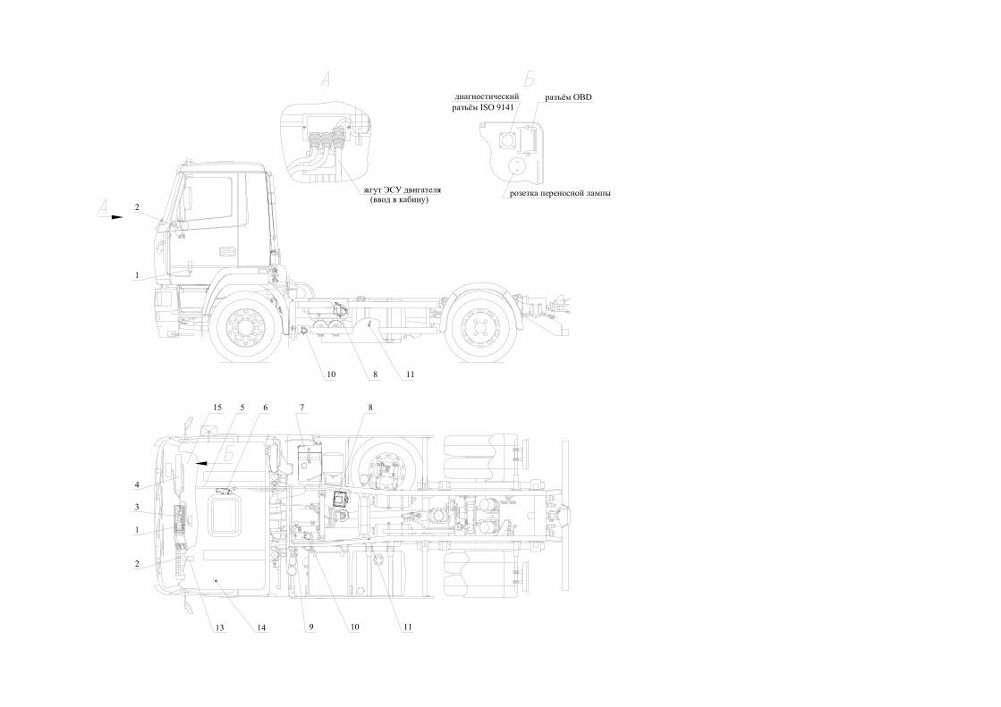
1 – interface electronic block(VECU;)2 – tahograph; 3 – block of the relay and safety devices; 4 – block of the switching equipment (BSE); 5 – bundle of the engine ECS; 6 – electronic engine; 7 – AdBlue tank; 8 – electronic module of the SCR system; 9 – SCR bundle; 10 – AdBlue dosage valve and sprayer injection; 11 – NOx sensor; 13 – electric pedal of fuel delivery; 14 – switch of the motor break; 15 – OBD diagnostic connector
Fig. 22a – arrangement of the engine elements ECS on the truck
Жгут ЭСУ двигателя Bundle of the engine ECS Диагностический разъем ISO 9141 ISO 9141 diagnostic connector Разъем OBD OBD connector Розетка переносной лампы Outlet of the portable lamp
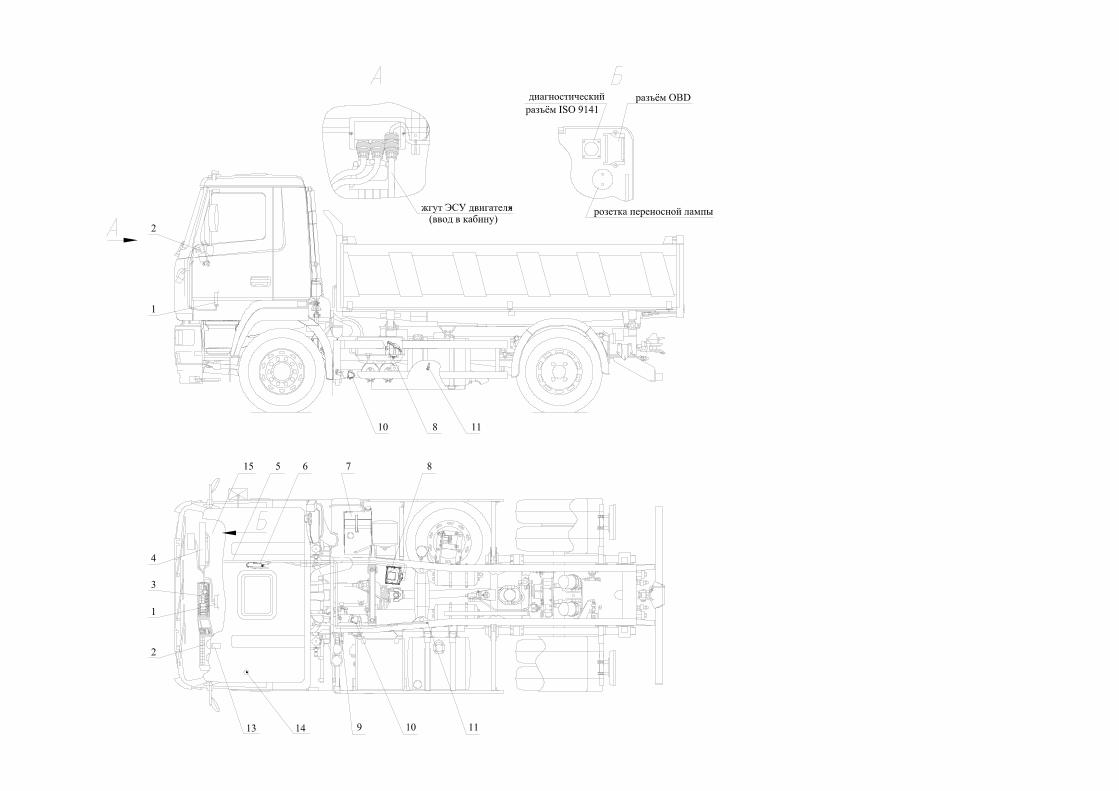
Р1 – interface electronic block(VECU;)2 – tahograph; 3 – block of the relay and safety devices; 4 – block of the switching equipment (BSE); 5 – bundle of the engine ECS; 6 – electronic engine; 7 – AdBlue tank; 8 – electronic module of the SCR system; 9 – SCR bundle; 10 – AdBlue dosage valve and sprayer injection; 11 – NOx sensor; 13 – electric pedal of fuel delivery; 14 – switch of the motor break; 15 – OBD diagnostic connector
Fig. 22b – arrangement of the engine elements ECS on the truck (A)Жгут ЭСУ двигателя Bundle of the engine ECS (Б)Диагностический разъем ISO 9141 ISO 9141 diagnostic connector Разъем OBD OBD connector Розетка переносной лампы Outlet of the portable lamp
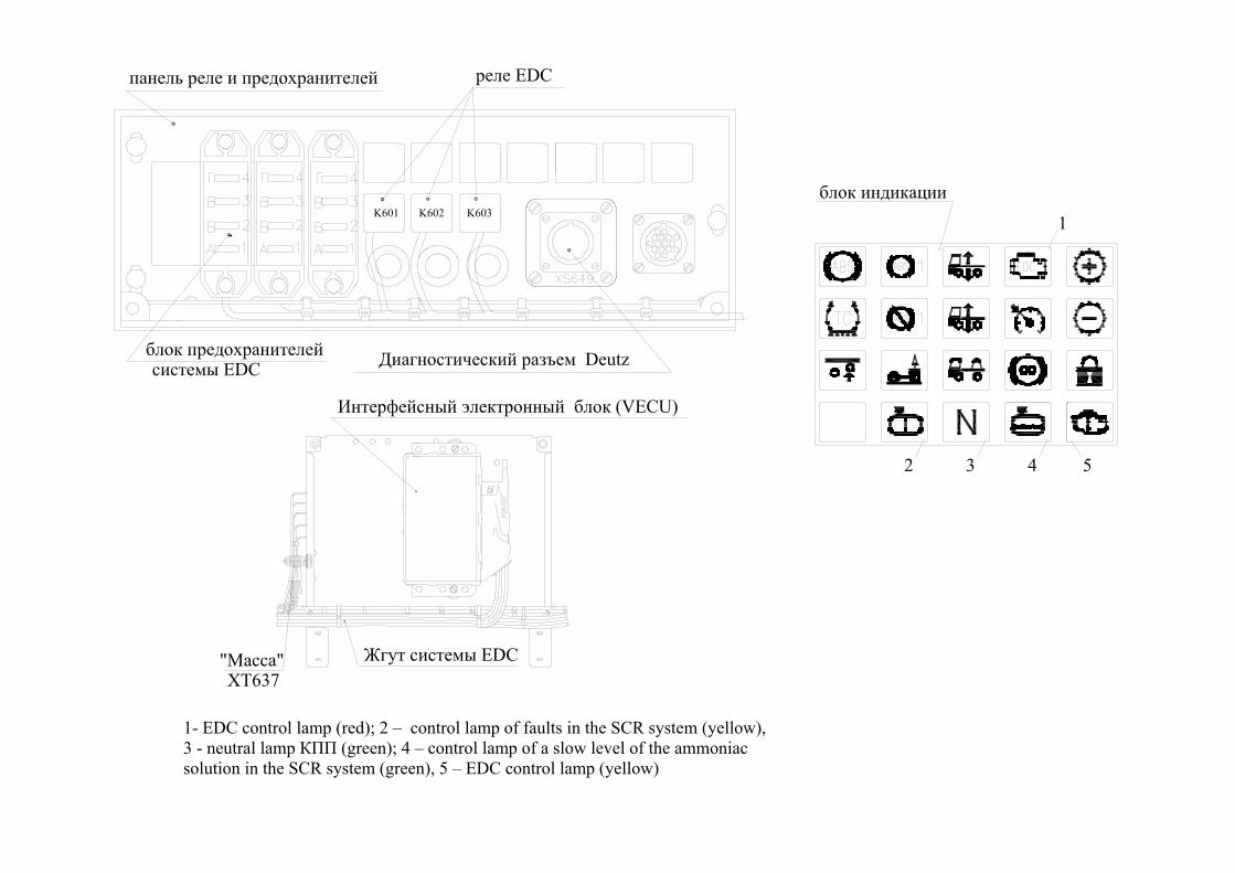
Интерфейсный электронный блок (VECU)
XT637"Масса" Жгут системы EDC
4 5
1
2 3
1- EDC control lamp (red); 2 – control lamp of faults in the SCR system (yellow), 3 - neutral lamp КПП (green); 4 – control lamp of a slow level of the ammoniac solution in the SCR system (green), 5 – ЕDC control lamp (yellow)
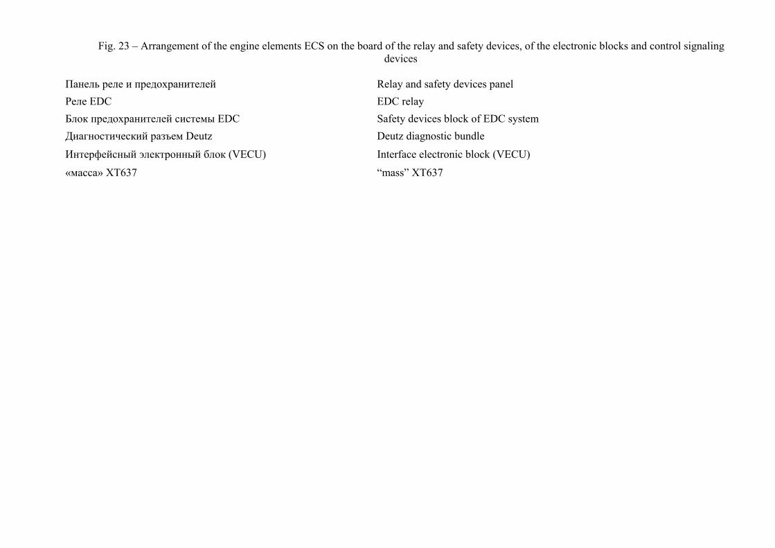
Fig. 23 – Arrangement of the engine elements ECS on the board of the relay and safety devices, of the electronic blocks and control signaling devices
Панель реле и предохранителей Relay and safety devices panel Реле EDC EDC relay Блок предохранителей системы EDC Safety devices block of EDC system Диагностический разъем Deutz Deutz diagnostic bundle
Интерфейсный электронный блок (VECU) Interface electronic block (VECU)
«масса» ХТ637 “mass” XT637
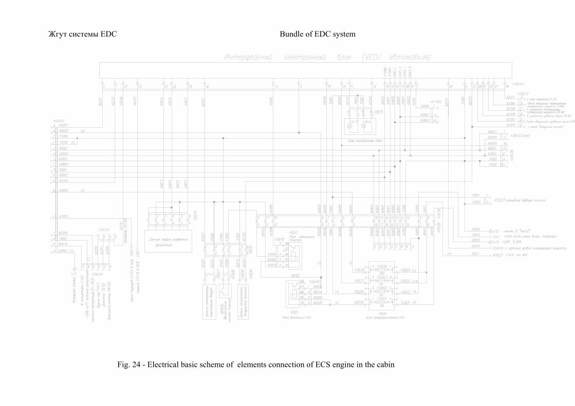
Жгут системы EDC Bundle of EDC system
Fig. 24 - Electrical basic scheme of elements connection of ECS engine in the cabin
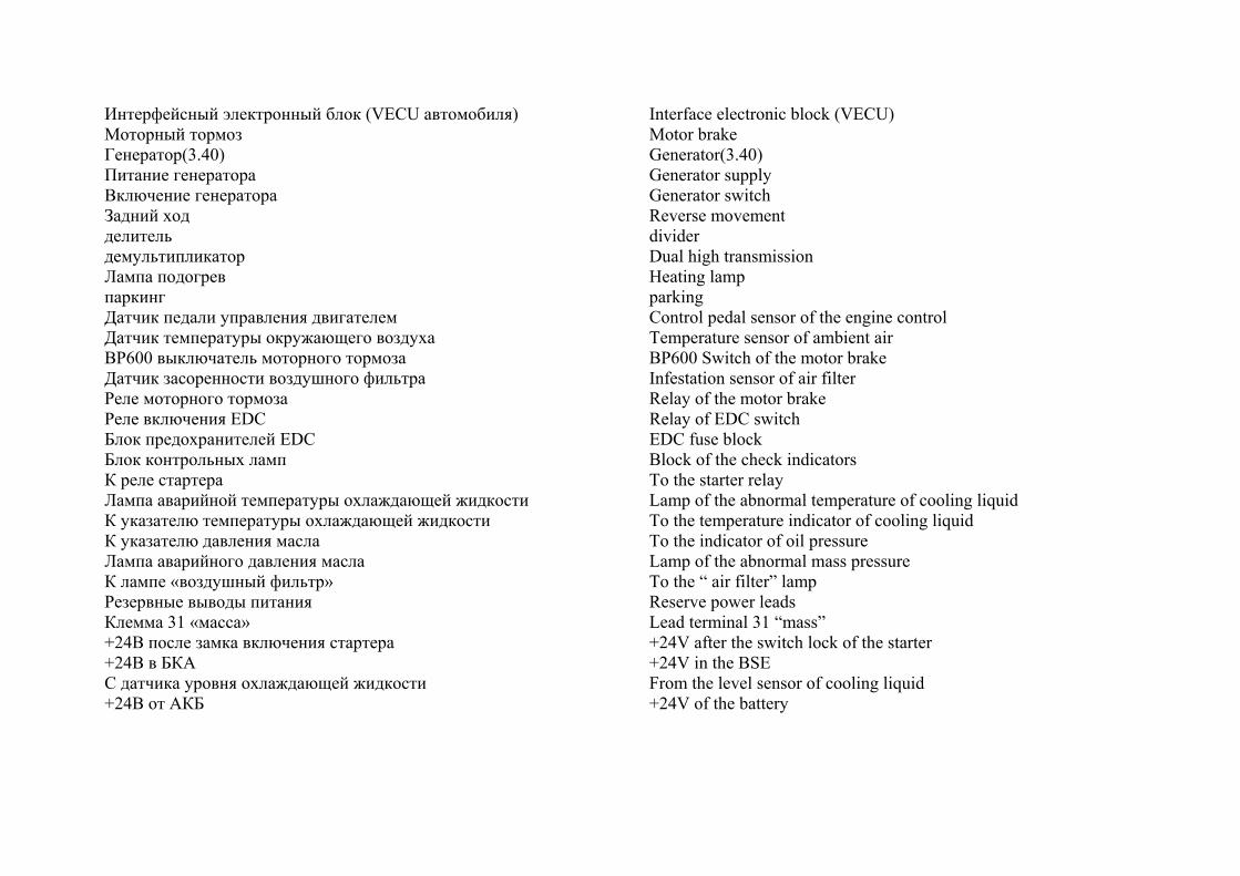
Интерфейсный электронный блок (VECU автомобиля) Interface electronic block (VECU) Моторный тормоз Motor brake Генератор(3.40) Generator(3.40) Питание генератора Generator supply Включение генератора Generator switch Задний ход Reverse movement делитель divider демультипликатор Dual high transmission Лампа подогрев Heating lamp паркинг parking Датчик педали управления двигателем Control pedal sensor of the engine control Датчик температуры окружающего воздуха Temperature sensor of ambient air ВР600 выключатель моторного тормоза BP600 Switch of the motor brake Датчик засоренности воздушного фильтра Infestation sensor of air filter Реле моторного тормоза Relay of the motor brake Реле включения EDC Relay of EDC switch Блок предохранителей EDC EDC fuse block Блок контрольных ламп Block of the check indicators К реле стартера To the starter relay Лампа аварийной температуры охлаждающей жидкости Lamp of the abnormal temperature of cooling liquid К указателю температуры охлаждающей жидкости To the temperature indicator of cooling liquid К указателю давления масла To the indicator of oil pressure Лампа аварийного давления масла Lamp of the abnormal mass pressure К лампе «воздушный фильтр» To the “ air filter” lamp Резервные выводы питания Reserve power leads Клемма 31 «масса» Lead terminal 31 “mass” +24В после замка включения стартера +24V after the switch lock of the starter +24В в БКА +24V in the BSE С датчика уровня охлаждающей жидкости From the level sensor of cooling liquid +24В от АКБ +24V of the battery
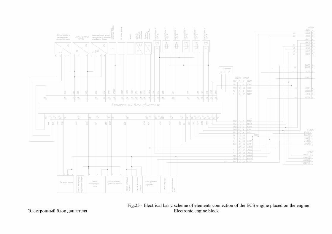
Fig.25 - Electrical basic scheme of elements connection of the ECS engine placed on the engine
Электронный блок двигателя Electronic engine block
Датчик уровня и температуры моторного масла Level and temperature sensor of engine oil Датчик давления топлива Sensor of fuel pressure Комбинированный датчик температуры и давления надувочного воздуха
Combined sensor of supercharging air temperature and pressure
Выключатель моторного тормоза Switch of the motor brake Эл. магн. клапан Electronic magnetic valve Датчик оборотов коленчатого вала Speed sensor of crankshaft Датчик оборотов распред. вала Speed sensor of the control shaft Эл.магн. клапан Electronic magnetic valve Датчик температуры наддувочного воздуха Supercharging air temperature sensor Датчик температуры масла Oil temperature sensor Датчик низкого давления топлива Fuel low pressure sensor Клапан моторного тормоза Motor brake valve Блок пускового подогрева Block of start heating Реле стартера Starter relay Клапан выхлопных газов Exhaust gases valve Генератор Generator
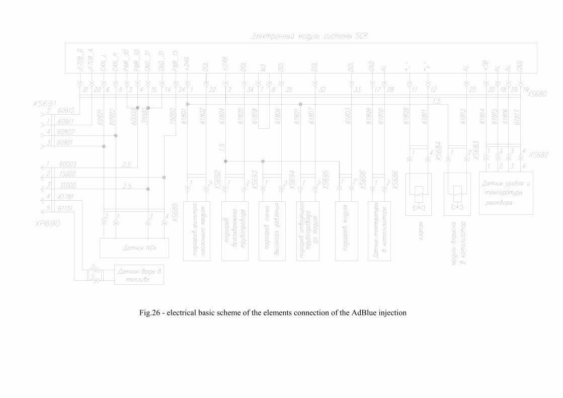
Fig.26 - electrical basic scheme of the elements connection of the AdBlue injection
Электронный модуль системы SCR Electronic module of the SCR system Датчик NOx NOx sensor Датчик воды в топливе Sensor of water in the fuel Подогрев фильтра насосного модуля Heating of the pumping module filter Подогрев всасывающего трубопровода Heating of the suction manifold Подогрев линии высокого давления Heating of the line of resultant pressure Подогрев отводящего трубопровода до модуля Heating of the pipe lateral up to the module Подогрев модуля Heating of the module Датчик температуры в катализаторе Temperature sensor in the accelerator Клапан Valve Модуль впрыска в катализатор Injection module for the accelerator Датчик уровня и температуры раствора Level and temperature sensor of solution
Simplified diagnostics According to the state of the controlling lamps a driver can define working capacity of the electronic system of the engine control and the SCR system. Controlling lamps are placed on the side shield (Fig.23) of the devices, composed of the indicator unit. While turning the key of the ignition switch, the “Devices” must briefly switch on, and if there are no any damages or disrepairs in the system, the lamps 1, 2, 4 and 5 must switch on (Fig. 23). Repeated lightning of one of the listed lamps will indicate the presence of any disrepair. Control lamp 1(red) shows that there are serious disrepairs in the engine control system. Attention! It is forbidden to start the engine when the control lamp is on with the sign EDC (item 1, Fig. 23)! If the lamp switches on during the truck movement, it is necessary to stop the truck and kill the motor. The truck movement is allowed only with the help of towing and the engine start is allowed after removing of all disrepairs at a service center. Control lamp 5 (yellow) warns a driver about disrepairs in the engine control system that are not connected with the risk of breakage of the engine or the safety of traffic. So the further truck movement is allowed and it is recommended to visit a nearby service center for the repair. Control lamp 2 (yellow) warns about defects in the SCR system (neutralization of exhaust gases). It is allowed to continue the truck movement and it is recommended to visit a nearby service center in order to clear the defects. Control lamp 4 (green) warns about low level of ammoniac solution in the AdBlue tank. It is recommended to fill the tank with the ammoniac solution (AdBlue) at a specialized refueling station equipped with the AdBlue fuel filling column. Control lamp 3 (green) informs about the location of the gear-change lever of the gear box in neutral position. When one of the gear is switched on - the lamp goes out. To start the engine it is necessary to fix the gear-change lever in neutral position, otherwise the engine won’t start! Full diagnostics Full diagnostics of the system is held with the help of specialized diagnostic equipment at a certified service center. The trucks, that have the lamps 1, 2 or 5 switched on, are liable to full diagnostics. In order to hold the full or computer diagnostics of the engine and its systems the truck has two special diagnostic connectors, one of them is placed under the middle cover of the facia (Fig.23), the latter one (OBD connector) is placed in the bottom of the facia on the right side opposite the passenger seat (Fig.22).
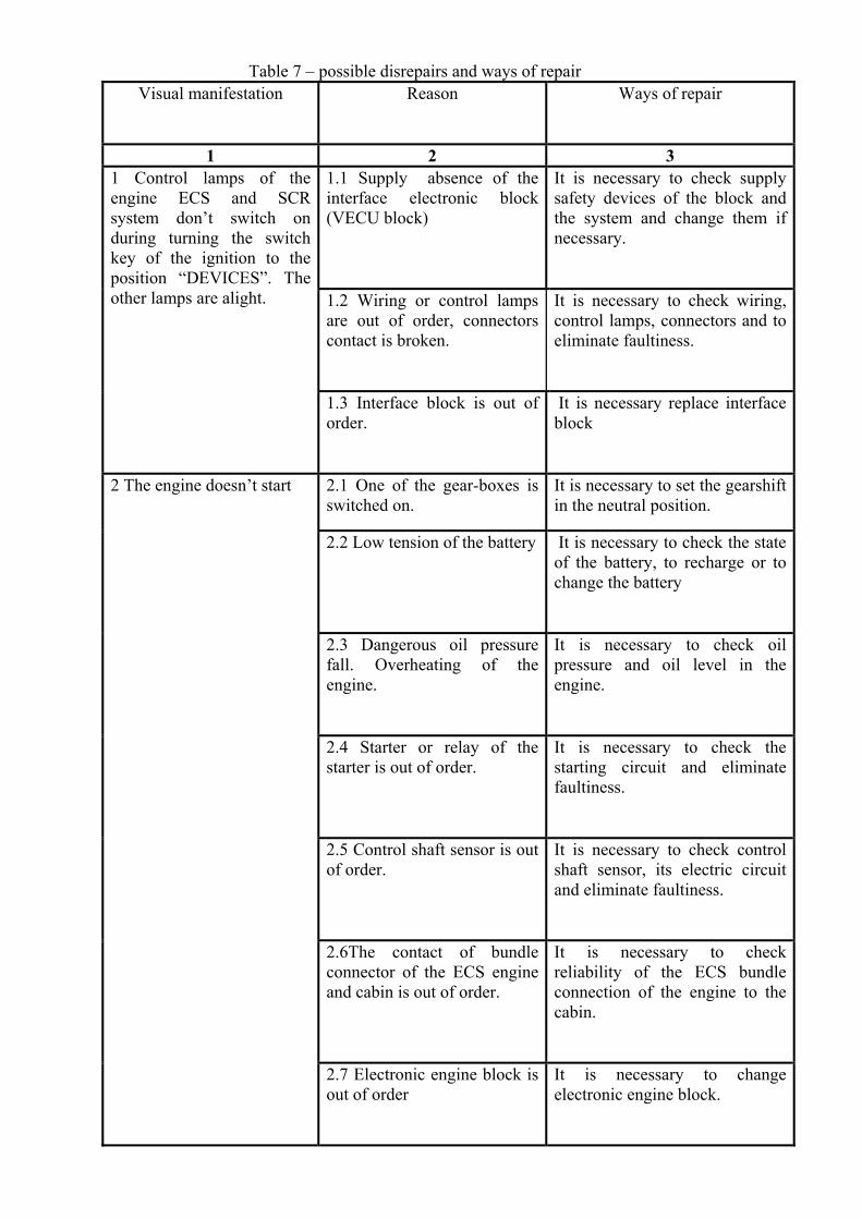
Table 7 – possible disrepairs and ways of repair Visual manifestation
Reason
Ways of repair
1 2 3
1.1 Supply absence of the interface electronic block (VECU block)
It is necessary to check supply safety devices of the block and the system and change them if necessary.
1.2 Wiring or control lamps are out of order, connectors contact is broken.
It is necessary to check wiring, control lamps, connectors and to eliminate faultiness.
1 Control lamps of the engine ECS and SCR system don’t switch on during turning the switch key of the ignition to the position “DEVICES”. The other lamps are alight.
1.3 Interface block is out of order.
It is necessary replace interface block
2.1 One of the gear-boxes is switched on.
It is necessary to set the gearshift in the neutral position.
2.2 Low tension of the battery It is necessary to check the state of the battery, to recharge or to change the battery
2.3 Dangerous oil pressure fall. Overheating of the engine.
It is necessary to check oil pressure and oil level in the engine.
2.4 Starter or relay of the starter is out of order.
It is necessary to check the starting circuit and eliminate faultiness.
2.5 Control shaft sensor is out of order.
It is necessary to check control shaft sensor, its electric circuit and eliminate faultiness.
2.6The contact of bundle connector of the ECS engine and cabin is out of order.
It is necessary to check reliability of the ECS bundle connection of the engine to the cabin.
2 The engine doesn’t start
2.7 Electronic engine block is out of order
It is necessary to change electronic engine block.
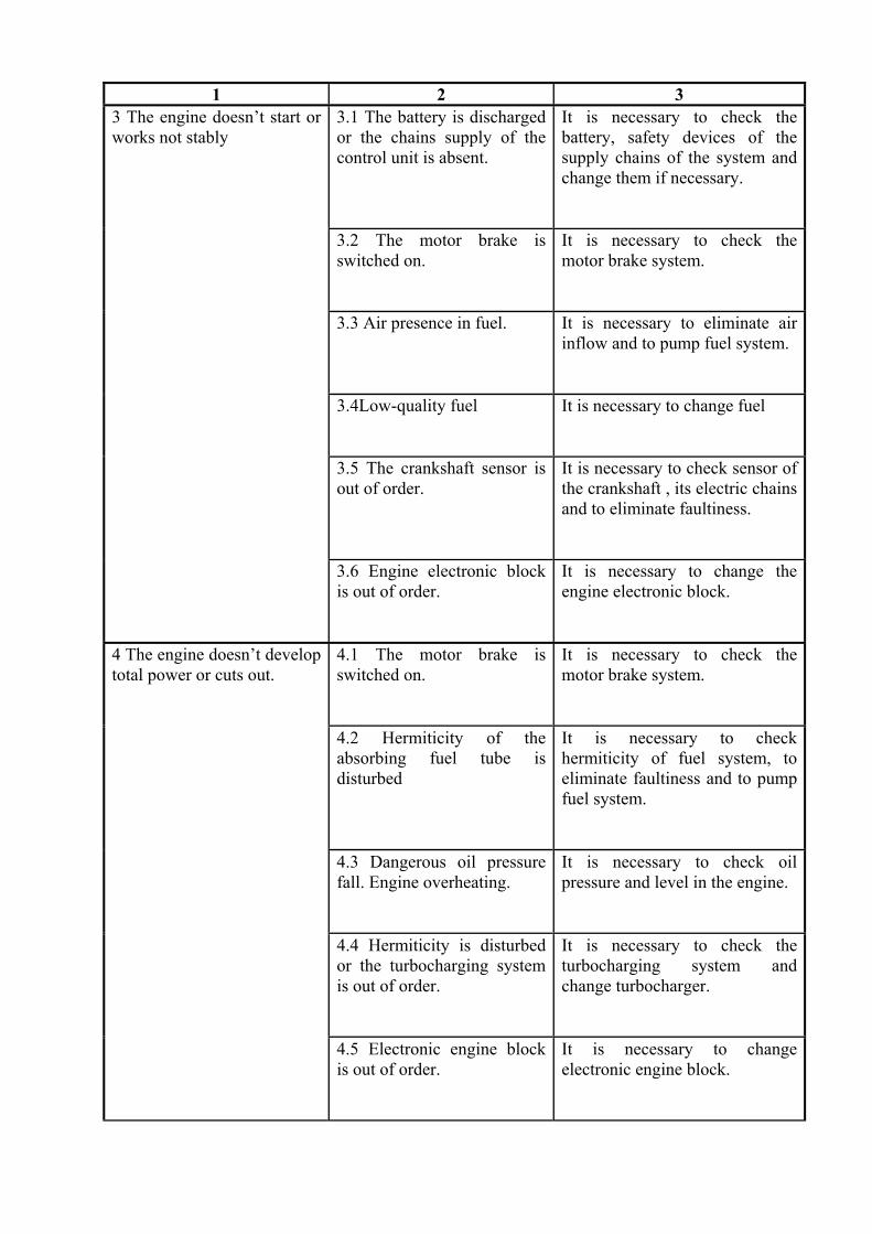
1 2 3
3.1 The battery is discharged or the chains supply of the control unit is absent.
It is necessary to check the battery, safety devices of the supply chains of the system and change them if necessary.
3.2 The motor brake is switched on.
It is necessary to check the motor brake system.
3.3 Air presence in fuel. It is necessary to eliminate air
inflow and to pump fuel system.
3.4Low-quality fuel It is necessary to change fuel
3.5 The crankshaft sensor is out of order.
It is necessary to check sensor of the crankshaft , its electric chains and to eliminate faultiness.
3 The engine doesn’t start or works not stably
3.6 Engine electronic block is out of order.
It is necessary to change the engine electronic block.
4.1 The motor brake is switched on.
It is necessary to check the motor brake system.
4.2 Hermiticity of the absorbing fuel tube is disturbed
It is necessary to check hermiticity of fuel system, to eliminate faultiness and to pump fuel system.
4.3 Dangerous oil pressure fall. Engine overheating.
It is necessary to check oil pressure and level in the engine.
4.4 Hermiticity is disturbed or the turbocharging system is out of order.
It is necessary to check the turbocharging system and change turbocharger.
4 The engine doesn’t develop total power or cuts out.
4.5 Electronic engine block is out of order.
It is necessary to change electronic engine block.
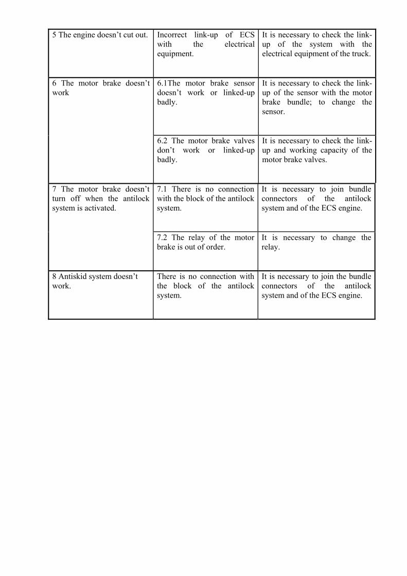
5 The engine doesn’t cut out.
Incorrect link-up of ECS with the electrical equipment.
It is necessary to check the link-up of the system with the electrical equipment of the truck.
6.1The motor brake sensor doesn’t work or linked-up badly.
It is necessary to check the link-up of the sensor with the motor brake bundle; to change the sensor.
6 The motor brake doesn’t work
6.2 The motor brake valves don’t work or linked-up badly.
It is necessary to check the link-up and working capacity of the motor brake valves.
7.1 There is no connection with the block of the antilock system.
It is necessary to join bundle connectors of the antilock system and of the ECS engine.
7 The motor brake doesn’t turn off when the antilock system is activated.
7.2 The relay of the motor brake is out of order.
It is necessary to change the relay.
8 Antiskid system doesn’t work.
There is no connection with the block of the antilock system.
It is necessary to join the bundle connectors of the antilock system and of the ECS engine.
SCR SYSTEM
The engine meeting requirements of Euro-4 ecology standards is installed on your truck. Performance of Euro-4 requirements is provided due to the SCR system – injection of an
ammoniac solution to the engine exhaust system and transformations of harmful oxides of nitrogen into nitrogen and water occurring at high temperature in the catalyst.
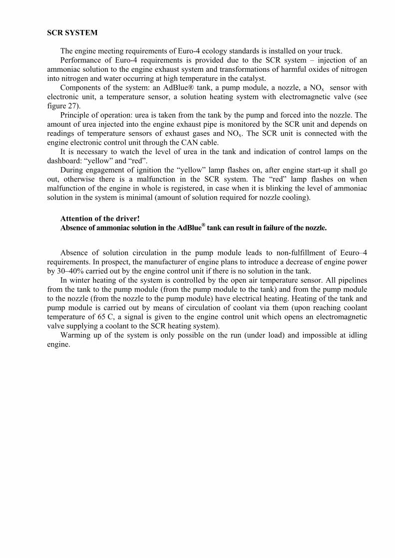
Components of the system: an AdBlue® tank, a pump module, a nozzle, a NOx sensor with electronic unit, a temperature sensor, a solution heating system with electromagnetic valve (see figure 27).
Principle of operation: urea is taken from the tank by the pump and forced into the nozzle. The amount of urea injected into the engine exhaust pipe is monitored by the SCR unit and depends on readings of temperature sensors of exhaust gases and NOx. The SCR unit is connected with the engine electronic control unit through the CAN cable.
It is necessary to watch the level of urea in the tank and indication of control lamps on the dashboard: “yellow” and “red”.
During engagement of ignition the “yellow” lamp flashes on, after engine start-up it shall go out, otherwise there is a malfunction in the SCR system. The “red” lamp flashes on when malfunction of the engine in whole is registered, in case when it is blinking the level of ammoniac solution in the system is minimal (amount of solution required for nozzle cooling).
Attention of the driver! Absence of ammoniac solution in the AdBlue® tank can result in failure of the nozzle.
Absence of solution circulation in the pump module leads to non-fulfillment of Еeuro–4 requirements. In prospect, the manufacturer of engine plans to introduce a decrease of engine power by 30–40% carried out by the engine control unit if there is no solution in the tank.
In winter heating of the system is controlled by the open air temperature sensor. All pipelines from the tank to the pump module (from the pump module to the tank) and from the pump module to the nozzle (from the nozzle to the pump module) have electrical heating. Heating of the tank and pump module is carried out by means of circulation of coolant via them (upon reaching coolant temperature of 65 C, a signal is given to the engine control unit which opens an electromagnetic valve supplying a coolant to the SCR heating system).
Warming up of the system is only possible on the run (under load) and impossible at idling engine.
Figure 27 – SCR System operation scheme
temperature sensor- датчик температуры
exhaust gases- выхлопные газы
SCR muffler- глушитель SCR
dosing module- дозирующий модуль
valve- клапан
pump feed module- подающий модуль насоса
Adblue feed (displacement)- подача (перемещение) Adblue
coolant in the engine- охлаждающая жидкость в двигателе
tank ventilation- вентилирование бака
tank with AdBlue- бак с Adblue
level and solution temperature sensor- датчик уровня и температуры раствора
heated tubes with AdBlue solution- подогреваемые трубы с раствором Adblue
TIRES MOUNTING AND DISMOUNTING
Tire fitting shall be performed in a tire fitting section or premises meant for these operations using special equipment, accessories and tools.
During tire fitting it is strictly forbidden: –to start dismounting the tire from the rim without making sure it is completely deflated; –to dismount the tire from the automobile without taking measures for preventing rolling of the
automobile; – to use hammers, crow-bars and other heavy things that can deform wheel parts; – to mount the tire on non-corresponding wheel rim; – to use tires having edge fins, cuts and other damages and wheels having geometry violation of nicks,
cracks, burs, rust markings on the landing surface; damages preventing the mounting process; – to start up tires pumping without assurance that it is in the right position on the rim – to pump tire out of special barrier and in road conditions without safety regulations
compliance - Dismounting of one from coupled wheels without use of jack, with collision of second wheel on lugs; – Pump the tire up to pressure, which exceeds set standards Pump the tire, without taking off from the truck at decompression in tire more than 40 percent
from nominal. It is necessary to remember that wheels (metallic part) related to the category of nonrepairable, that is why in crack detection the wheel is rejected i.e. it should be changed.
Fastening of spare wheel
Fastening of spare wheel of MAZ-631236, 534035 trucks is indicated on the Figure28.
For a wheel descending
-unscrew nuts 4 mounting holder 6 to the bracket 1
- lower a wheel, revolving by fixed driver in clamping 10 (handle of pump of cab lifting is used) anticlockwise
- set free holder from wheel disk
Wheel lifting and its fastening are made in reverse order. If during the wheel lifting, the
resistance of shaft revolution is absent or it is insignificant, so it is necessary to draw up nut 7,
regulating effort of spring disk pack 8.
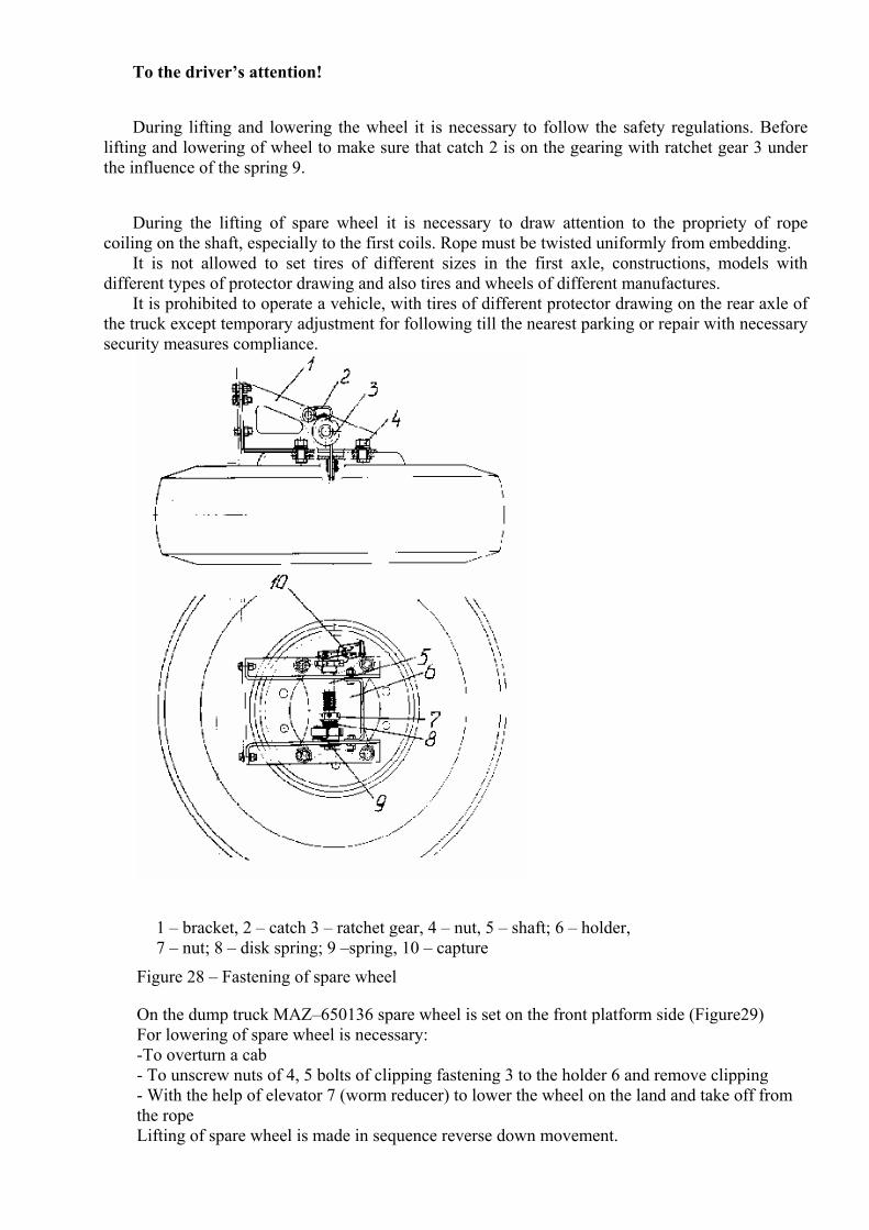
To the driver’s attention!
During lifting and lowering the wheel it is necessary to follow the safety regulations. Before lifting and lowering of wheel to make sure that catch 2 is on the gearing with ratchet gear 3 under the influence of the spring 9.
During the lifting of spare wheel it is necessary to draw attention to the propriety of rope coiling on the shaft, especially to the first coils. Rope must be twisted uniformly from embedding.
It is not allowed to set tires of different sizes in the first axle, constructions, models with different types of protector drawing and also tires and wheels of different manufactures.
It is prohibited to operate a vehicle, with tires of different protector drawing on the rear axle of the truck except temporary adjustment for following till the nearest parking or repair with necessary security measures compliance.
1 – bracket, 2 – catch 3 – ratchet gear, 4 – nut, 5 – shaft; 6 – holder, 7 – nut; 8 – disk spring; 9 –spring, 10 – capture
Figure 28 – Fastening of spare wheel
On the dump truck МАZ–650136 spare wheel is set on the front platform side (Figure29) For lowering of spare wheel is necessary: -To overturn a cab - To unscrew nuts of 4, 5 bolts of clipping fastening 3 to the holder 6 and remove clipping - With the help of elevator 7 (worm reducer) to lower the wheel on the land and take off from the rope Lifting of spare wheel is made in sequence reverse down movement.
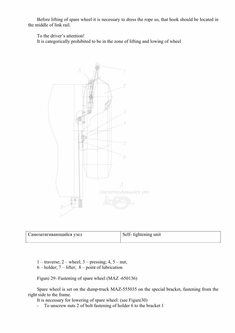
Before lifting of spare wheel it is necessary to dress the rope so, that hook should be located in the middle of link rail.
To the driver’s attention! It is categorically prohibited to be in the zone of lifting and lowing of wheel
Самозатягивающийся узел Self- tightening unit
1 – traverse; 2 – wheel; 3 – pressing; 4, 5 – nut; 6 – holder; 7 – lifter; 8 – point of lubrication Figure 29- Fastening of spare wheel (MAZ -650136) Spare wheel is set on the dump-truck MAZ-555035 on the special bracket, fastening from the
right side to the frame. It is necessary for lowering of spare wheel: (see Figure30) - To unscrew nuts 2 of bolt fastening of holder 6 to the bracket 1
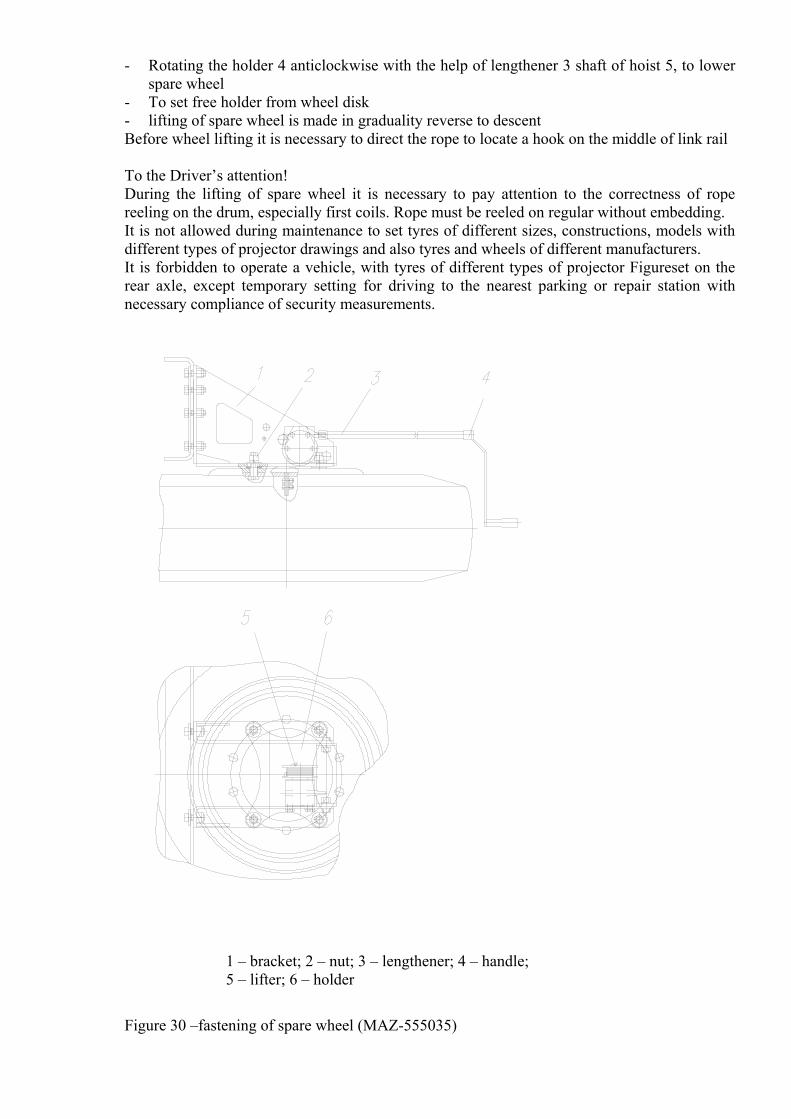
- Rotating the holder 4 anticlockwise with the help of lengthener 3 shaft of hoist 5, to lower spare wheel
- To set free holder from wheel disk - lifting of spare wheel is made in graduality reverse to descent Before wheel lifting it is necessary to direct the rope to locate a hook on the middle of link rail To the Driver’s attention! During the lifting of spare wheel it is necessary to pay attention to the correctness of rope reeling on the drum, especially first coils. Rope must be reeled on regular without embedding. It is not allowed during maintenance to set tyres of different sizes, constructions, models with different types of projector drawings and also tyres and wheels of different manufacturers. It is forbidden to operate a vehicle, with tyres of different types of projector Figureset on the rear axle, except temporary setting for driving to the nearest parking or repair station with necessary compliance of security measurements.
1 – bracket; 2 – nut; 3 – lengthener; 4 – handle; 5 – lifter; 6 – holder
Figure 30 –fastening of spare wheel (MAZ-555035)
Mechanism of dump-truck lifter Lifting mechanism (tipping mechanism) - hydraulic, single cylinder with electro pneumatic
distant control, with direct influence in the platform. Mechanism provides independent separate control of platform lifting of a dump-truck with the
49о–3о angle, lowing, stop in interposition, automatic restriction of angle of lifting, shaking of laden platform in the end of lifting for complete cargo fall.
Besides, automatic fall and closing of back header are provided. Schemes of dump-trucks platform lifting with back dumping are depicted in drawings 33 and 34
To the driver’s attention! Switching of power take-off should be made at air pressure in pneumatic system not less than
500 kPa. Hoisting mechanism control of truck platform with rear unloading Hoisting mechanism control of truck platform is implemented on the flat surface of the driver
cab with a help of switch (Figure 35), located on devices dashboard (see Figure6, 23). Before platform lifting is necessary at working engine to be proved that air pressure in pneumatic system is lower than 500 kPa (if monometer shows less than 500 kPa, it is necessary to pump air preliminary).
Platform lifting should be made in next order: -To disconnect the clutch -To turn off the switch 22 (see Figure 6) -To turn the switch handle (Figure 35) in right position: Lifting -To low clutch pedal slowly increasing engine over speeding simultaneously. To tachometer it is necessary to support engine over speeding up to 1200–1500 rpm Monitoring in the mirror of rear view or rear window, to regulate the speed of platform lifting
slowly changing engine over speeding, gradually changing engine over speeding. To disconnect the clutch approximately on 2/3 of its switch length at moving-out of last pipe of
hydraulic cylinder and to turn the switch control of platform in neutral position. Meanwhile the platform should be stopped. Platform shaking is possible at the end of lifting.
For lowering of empty platform: To turn the handle of switch in outside left position –”lowering” -To move the handle switch in neutral position To turn off the switch 22 (see Figure 6) meanwhile locks of side should be closed At the necessity of platform stop in interposition during the process of lifting or lowering it is
enough to depress the pedal of clutch and move the handle of switch in neutral position.
Moving of the truck with lifted platform is forbidden to avoid bracket breakage and working surfaces of pipe of hydraulic cylinder damages.
It is forbidden to lower the platform unladed.
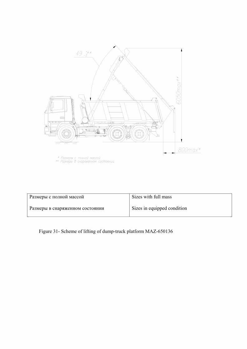
Размеры с полной массой
Размеры в снаряженном состоянии
Sizes with full mass
Sizes in equipped condition
Figure 31- Scheme of lifting of dump-truck platform МАZ-650136
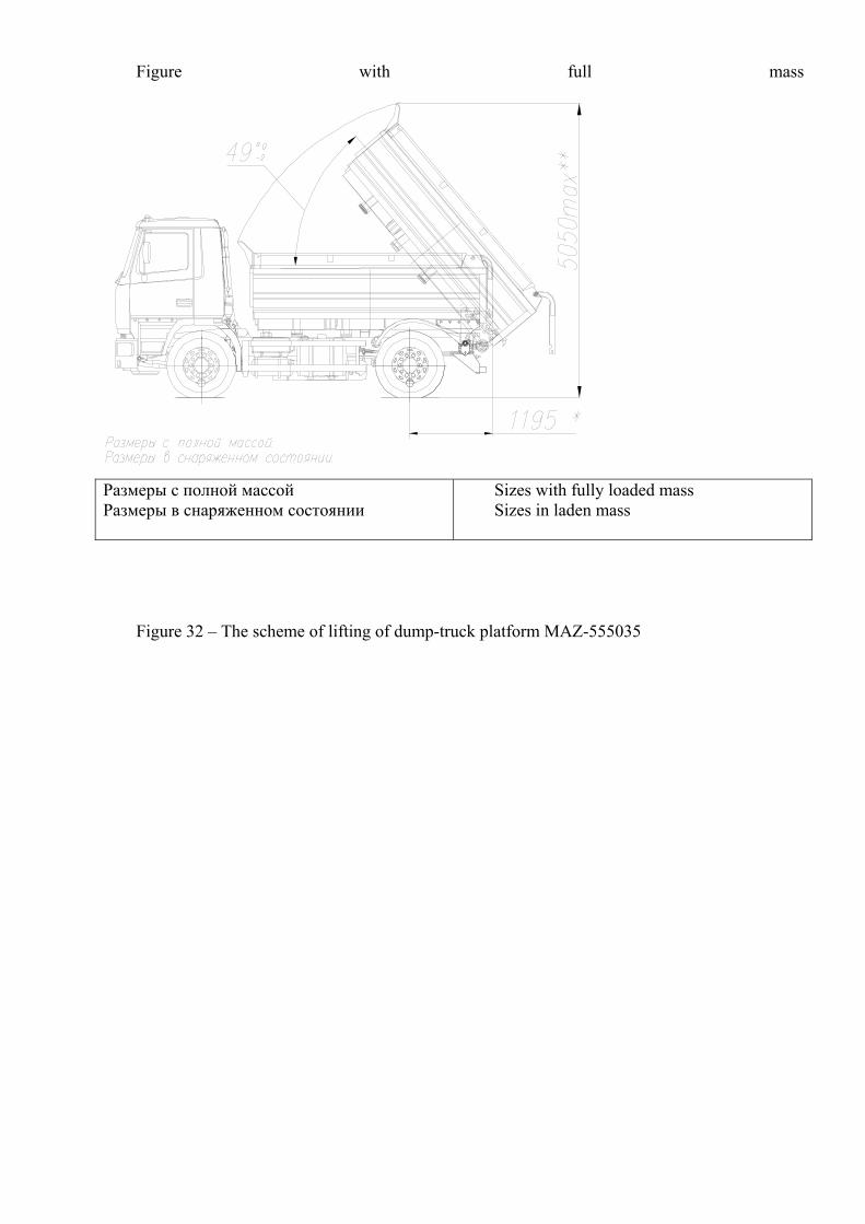
Figure with full mass
Размеры с полной массой Размеры в снаряженном состоянии
Sizes with fully loaded mass Sizes in laden mass
Figure 32 – The scheme of lifting of dump-truck platform МАZ-555035
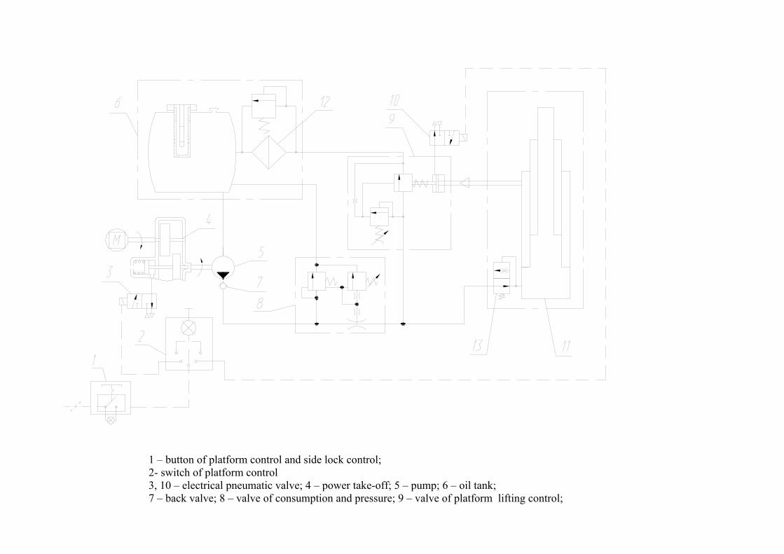
1 – button of platform control and side lock control; 2- switch of platform control 3, 10 – electrical pneumatic valve; 4 – power take-off; 5 – pump; 6 – oil tank; 7 – back valve; 8 – valve of consumption and pressure; 9 – valve of platform lifting control;
11 – hydrocylinder; 12 – filter; 13 – valve of speed restriction of platform lowering
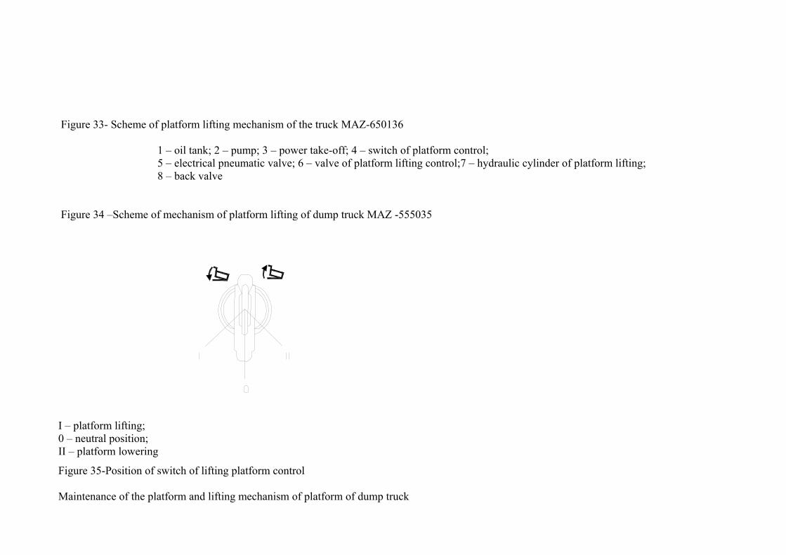
Figure 33- Scheme of platform lifting mechanism of the truck МАZ-650136
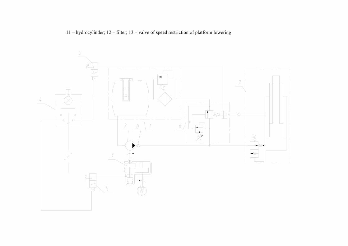
1 – oil tank; 2 – pump; 3 – power take-off; 4 – switch of platform control; 5 – electrical pneumatic valve; 6 – valve of platform lifting control;7 – hydraulic cylinder of platform lifting; 8 – back valve
Figure 34 –Scheme of mechanism of platform lifting of dump truck MAZ -555035
I – platform lifting; 0 – neutral position; II – platform lowering
Figure 35-Position of switch of lifting platform control
Maintenance of the platform and lifting mechanism of platform of dump truck
During operation of platform lifting mechanism is necessary to follow next rules: 1 If it is necessary to work under the platform to fix the platform with support to avoid accident (cargo presence in the platform is intolerable) 2 Not to overload dump truck more than standard norm and follow equal cargo distribution on the platform without allowing front part overloading 3 To make lubrication of all joints and units according to hematological map regularly 4 In proper time to trace and pull the oil pipes connection, air pipes and hoses, preventing oil and air leakage 5 To follow oil level in the tank. To add oil to the upper mark at descending oil level lower than second marking on the oil level indication. Adding oil
should be filtered properly 6 To change oil following hematological map. Filtered elements of oil filter tank should be flushed in diesel fuel and blew with pressed air at every oil
change To unscrew plug in the tank and filling cover for oil change. To turn the plug on the tank and fill in properly filtered oil in the tank in relief fitting pour. For urgent oil pouring it is necessary to disconnect suction hose from foot pipe and pour oil in the tank It is necessary to take into account that dirty oil is a major reason of premature deterioration and unit defect of lifting mechanism and especially pump. Axial piston pump «Meiller» of high pressure is sensible to the overload and to clearance of applying oil. At refilling and oil change is necessary to
filter it in a proper way, without getting into the tank of bodies and water. It is categorically forbidden to use in hydraulic system oil grades which are not provided in hematological map. The necessity of disassemble for changing of packing collars or guiding semi rings and bushings can appear during the operation process of hydraulic
cylinder. For this reason to take off hydraulic cylinder from the truck to unscrew down cover and extract pull-out pipes from the body. For removing worn-out bushing (sleeve) to take out stop ring locking it, than bushing is easy retrieved from the pipe. To draw attention to the condition of guiding semi rings at change of sealing rings It is necessary to change them with the thickness of wear more than 0.3 - 0.5 mm At cylinder assembly to trace that stop rings are tucked in grooves properly to avoid pull-out of bushings during platform lifting After long operation insignificant oil flows can appear at the surfaces of pulling-out links of Hydro cylinder. They can lead to the scraping of oil layer by sealing rings Oil flows should be removed with clean dry rag. Abundant flows indicate in sealing rings wear. In this case sealing rings and protective washers should be changed as the presence of oil on the
working surfaces of cylinder pipes can lead to the contamination and consequently to the rapid part wear At every oil change it is recommended to unscrew the plug of hydrocylinder on the bottom for condensate drain. According to the operation experience, water coming to the hydraulic system is collected in the cylinder, it freezes in winter time and ice inside of
cylinder obstacles complete platform lowering what can lead to the serious cylinder breakage. Periodically it is necessary to check the valve work 6 (see Figure33) 9 (see Figure34). Slow platform lifting indicates to the seat wear and in case of diaphragm break at inflowing of pressed air in the chamber cavity, it will be coming out
with specific hissing.
Oil leakage through drainage hole in the valve frame indicates to the wear or damage of sealing ring valve. Air outlet through the hole testifies about wear or other ring damage At valve disassembling is categorically forbidden to break safeguard adjustment. During truck operation there is necessity to check the condition and correctness of adjustment of rope of valve control of the truck.
Adjustment works
Declutching drive
Declutching drive – hydraulic with pneumatic booster is depicted on the Figure36.
Free pedal movement of clutch 5-7 mm is regulated by the bolt 6. During operation at the necessity it is allowed to adjust free movement by the length rod change 3, by unscrewing of lock - nut. At declutching it is necessary to adjust full speed of pedal providing rod motion pneumatic hydraulic unit 19, 5–22, 3 mm with the help of 4 and 8 bolts. At filling of the system of hydraulic drive of clutch: working fluid should be discharged into the system of hydraulic drive under the overpressure (200-
300 kPa) through preliminary unscrewing on (1-2) turnover of valve 6 till the complete disappearing of air bubbles in fluid going out into the tank 5. It is allowed to fill in the system through the tank 5 under pressure (200 -300) kPa at unscrewing valve 6 at (1-2) till the fluid going out through the valve
will not be clean without air bubbles. Tighten up valve 6 and put on cover after filling the system. Fluid volume in the tank leads to the level (10- 25) mm lower than filler cap.
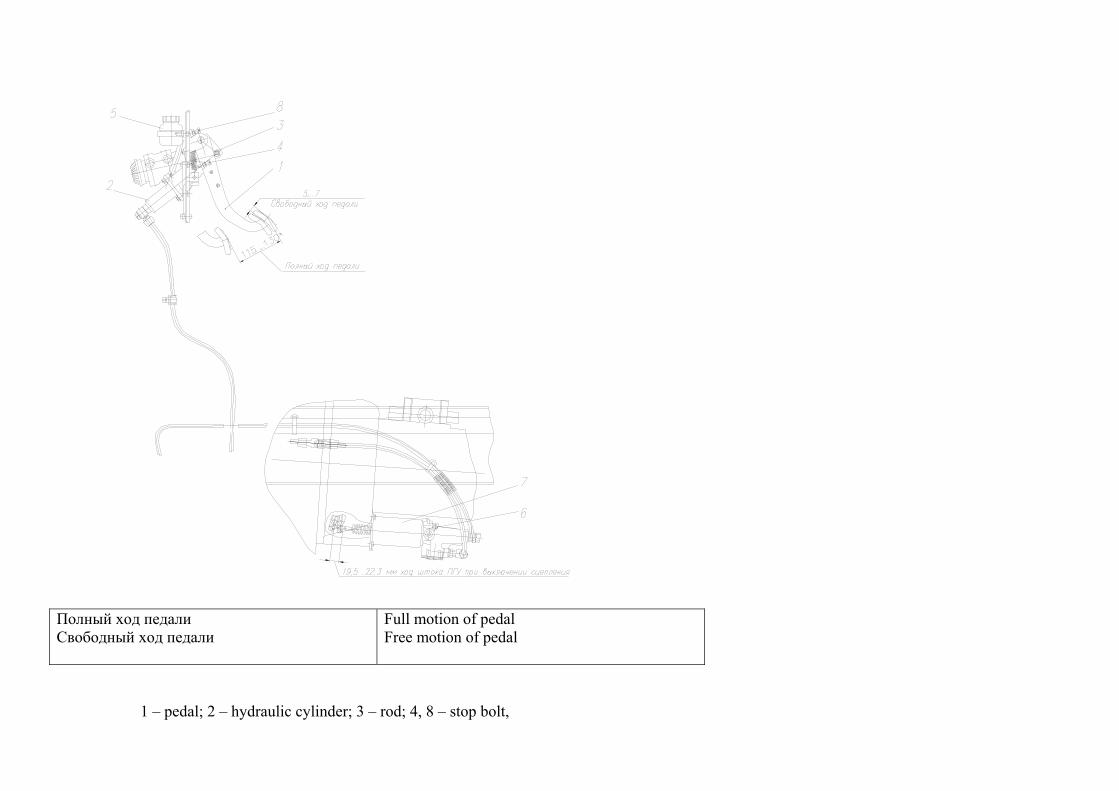
Полный ход педали Свободный ход педали
Full motion of pedal Free motion of pedal
1 – pedal; 2 – hydraulic cylinder; 3 – rod; 4, 8 – stop bolt,
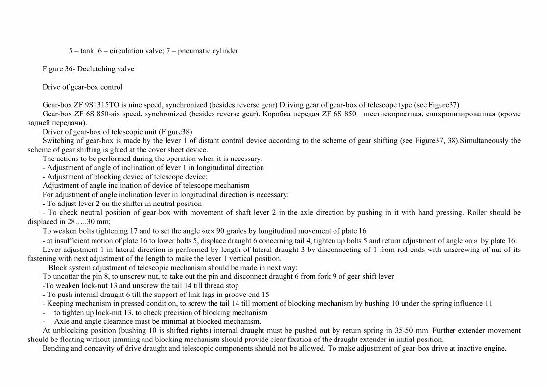
5 – tank; 6 – circulation valve; 7 – pneumatic cylinder Figure 36- Declutching valve
Drive of gear-box control
Gear-box ZF 9S1315TO is nine speed, synchronized (besides reverse gear) Driving gear of gear-box of telescope type (see Figure37) Gear-box ZF 6S 850-six speed, synchronized (besides reverse gear). Коробка передач ZF 6S 850—шестискоростная, синхронизированная (кроме
задней передачи). Driver of gear-box of telescopic unit (Figure38) Switching of gear-box is made by the lever 1 of distant control device according to the scheme of gear shifting (see Figure37, 38).Simultaneously the
scheme of gear shifting is glued at the cover sheet device. The actions to be performed during the operation when it is necessary: - Adjustment of angle of inclination of lever 1 in longitudinal direction - Adjustment of blocking device of telescope device; Adjustment of angle inclination of device of telescope mechanism For adjustment of angle inclination lever in longitudinal direction is necessary: - To adjust lever 2 on the shifter in neutral position - To check neutral position of gear-box with movement of shaft lever 2 in the axle direction by pushing in it with hand pressing. Roller should be
displaced in 28…..30 mm; To weaken bolts tightening 17 and to set the angle «α» 90 grades by longitudinal movement of plate 16 - at insufficient motion of plate 16 to lower bolts 5, displace draught 6 concerning tail 4, tighten up bolts 5 and return adjustment of angle «α» by plate 16. Lever adjustment 1 in lateral direction is performed by length of lateral draught 3 by disconnecting of 1 from rod ends with unscrewing of nut of its
fastening with next adjustment of the length to make the lever 1 vertical position. Block system adjustment of telescopic mechanism should be made in next way: To uncottar the pin 8, to unscrew nut, to take out the pin and disconnect draught 6 from fork 9 of gear shift lever -To weaken lock-nut 13 and unscrew the tail 14 till thread stop - To push internal draught 6 till the support of link lags in groove end 15 - Keeping mechanism in pressed condition, to screw the tail 14 till moment of blocking mechanism by bushing 10 under the spring influence 11 - to tighten up lock-nut 13, to check precision of blocking mechanism - Axle and angle clearance must be minimal at blocked mechanism. At unblocking position (bushing 10 is shifted rights) internal draught must be pushed out by return spring in 35-50 mm. Further extender movement
should be floating without jamming and blocking mechanism should provide clear fixation of the draught extender in initial position. Bending and concavity of drive draught and telescopic components should not be allowed. To make adjustment of gear-box drive at inactive engine.
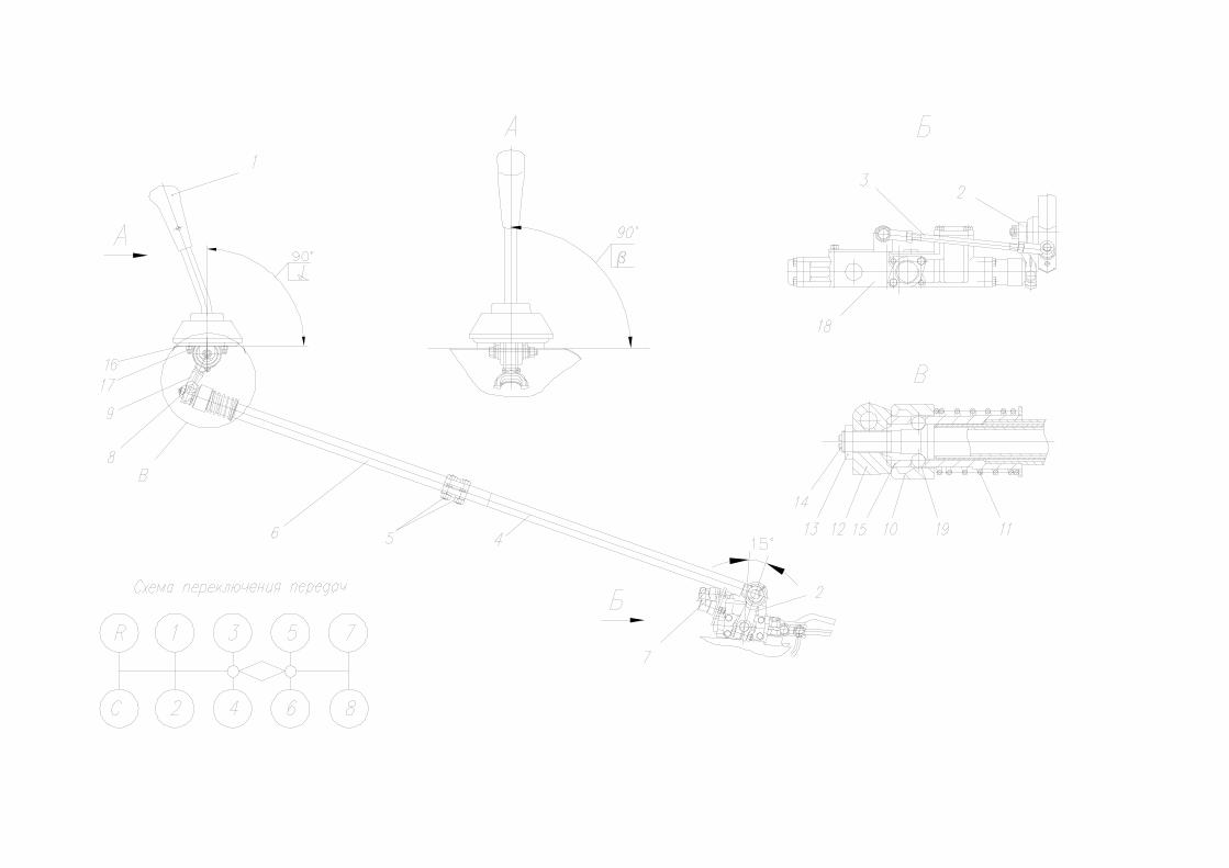
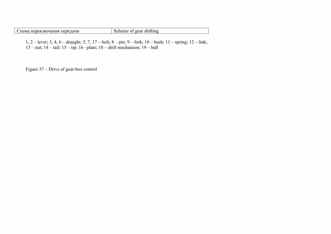
Схема переключения передачи Scheme of gear shifting 1, 2 – lever; 3, 4, 6 – draught; 5, 7, 17 – bolt; 8 – pin; 9 – fork; 10 – bush; 11 – spring; 12 – link; 13 – nut; 14 – tail; 15 – tip; 16 –plate; 18 – shift mechanism; 19 – ball
Figure 37 – Drive of gear-box control
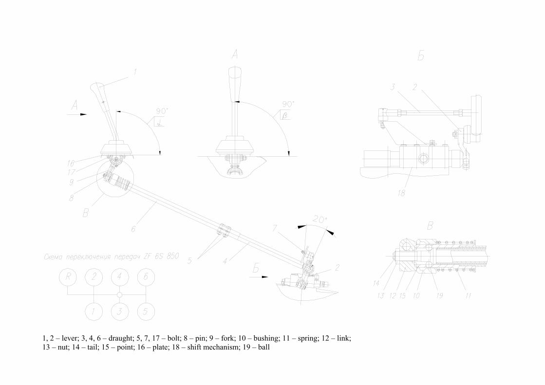
1, 2 – lever; 3, 4, 6 – draught; 5, 7, 17 – bolt; 8 – pin; 9 – fork; 10 – bushing; 11 – spring; 12 – link; 13 – nut; 14 – tail; 15 – point; 16 – plate; 18 – shift mechanism; 19 – ball
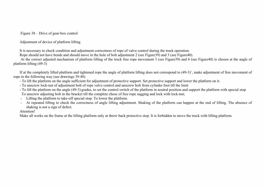
Figure 38 – Drive of gear-box control Adjustment of device of platform lifting
It is necessary to check condition and adjustment correctness of rope of valve control during the truck operation. Rope should not have bends and should move in the hole of bolt adjustment 2 (see Figure39) and 3 (see Figure40). At the correct adjusted mechanism of platform lifting of the truck free rope movement 3 (see Figure39) and 6 (see Figure40) is chosen at the angle of
platform lifting (49-3) If at the completely lifted platform and tightened rope the angle of platform lifting does not correspond to (49-3)˚, make adjustment of free movement of
rope in the following way (see drawings 39-40) - To lift the platform on the angle sufficient for adjustment of protective support. Set protective support and lower the platform on it. - To unscrew lock-nut of adjustment bolt of rope valve control and unscrew bolt from cylinder foot till the limit - To lift the platform on the angle (49-3) grades, to set the control switch of the platform in neutral position and support the platform with special stop
To unscrew adjusting bolt in the bracket till the complete chose of free rope sagging and lock with lock-nut; - Lifting the platform to take-off special stop. To lower the platform. - At repeated lifting to check the correctness of angle lifting adjustment. Shaking of the platform can happen at the end of lifting. The absence of
shaking is not a sign of defect. Attention! Make all works on the frame at the lifting platform only at threw back protective stop. It is forbidden to move the truck with lifting platform.
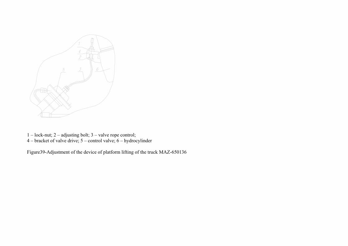
1 – lock-nut; 2 – adjusting bolt; 3 – valve rope control; 4 – bracket of valve drive; 5 – control valve; 6 – hydrocylinder
Figure39-Adjustment of the device of platform lifting of the truck MAZ-650136
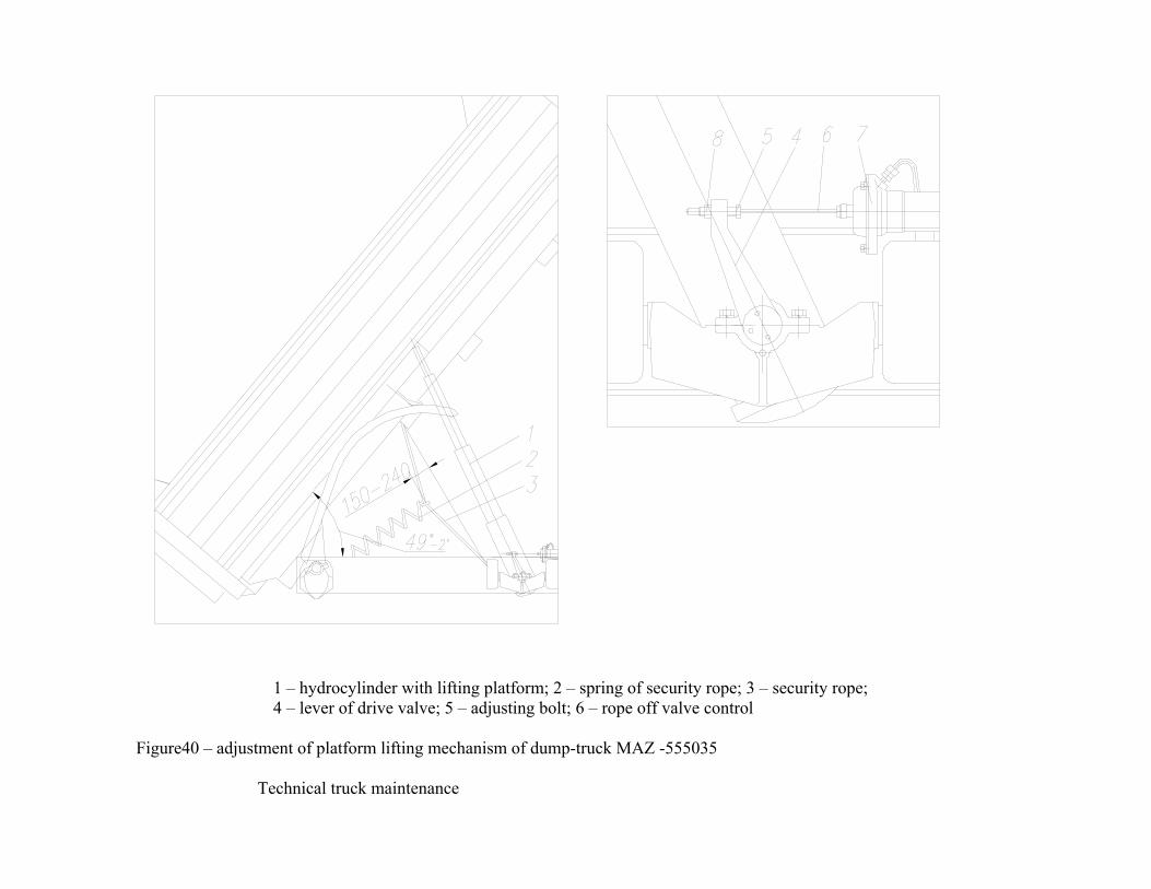
1 – hydrocylinder with lifting platform; 2 – spring of security rope; 3 – security rope; 4 – lever of drive valve; 5 – adjusting bolt; 6 – rope off valve control
Figure40 – adjustment of platform lifting mechanism of dump-truck MAZ -555035
Technical truck maintenance
Reliable truck work extensively depends on well-timed and qualified technical maintenance. Works, connected with adjustments and maintenance of devices of engine feed circuit, electrical equipment, ABS and also units of
hydraulic systems, pneumatic suspensions should be performed on the station of technical maintenance or special works where skilled specialists execute this work with quality and rapidly. After making works, connected with technical maintenance and with taking-off pneumatic, electric and hydraulic systems from the truck, to check and to remove contagions (bad contacts) of these systems with truck parts.
Maintenance of power unit (engine, clutch, gear box) is performed according to the instruction of plant – manufactures. Tightening torques of basic thread connections are presented in the supplement 3. Types and periodicity of technical maintenance
1 daily technical maintenance 2 First technical maintenance (А): - in 22,500 км for trucks (chassis); -in 15 000 km for dump-truck 3 Second technical maintenance (C): - in 45 000 км for trucks (chassis); - in every 30000 км dump-truck 4 Seasonal technical maintenance Seasonal technical maintenance combined with «С» or «А» and made two times per year at the truck (car) preparation to the operation
in winter time
Daily technical maintenance
To make washing works at necessity To check before engine launch: - Fuel margin in the tank (by indicator); - Lightning devices and light signaling - condition of trailer coupling - Oil level in engine Tire condition, wheels (also spare), spare-wheel carrier and their fastening, disks condition - Sufficient level of cooling fluid To check after engine start-up: - oil pressure; -air pressure in pneumatic system;
- Functioning of brake system, also parking brake It is necessary to check daily: - Fluid level in washer of wind shield; To check air pressure in tires at the necessity Works performed once per two weeks (on returning from trip, on the base): -To check the presence of oil leakage, fluid from engine, gear-box, driving axles, steering wheel, heating system, shock absorber of
suspension, hydro cylinders of hoisting mechanism of cab and platform; -to check the fluid level in the tank of drive of clutch control; - to check the absence of condensate in receivers at the temperature of environmental air close to 00; - in case of engine start-up difficulties be electrical starter to make maintenance of accumulator batteries following attached operation
manual; - to check free movement of steering wheel, the absence of clearances in steering links - (nutation of steering wheel) - To check (once per 2 weeks on returning from trip): -condition and work of platform hoisting mechanism; - hermeticity of system of platform hoisting mechanism Works performed monthly: -To check functioning of independent fluid heater
First technical maintenance (A)
At the truck maintenance after indicated run of performed works, foreseen by daily maintenance and besides:
1 To check splinting of ball pin nuts of steering links, pins of brake chambers forks and to eliminate defaults
2 To check condition of rubber branch pipes of entrance of engine branch pipe system and to tighten up links at the necessity 3 To make service maintenance of accumulator batteries according to attached operation manual, to check fastenings of accumulator
batteries, to clean them from dust, dirt, and electrolyte tracking, to clean air vents. To check connection of wires tops with clamps. To grease clamps with lubrication Litol-24.To check and tighten bolt of fastening of electrical wires connection “masses” on side bracket of engine support.
4 To check rod motion of brake chambers. If rod motion does not meet the size 38-44 мм, to check correctness of adjustment lever setting and find out a reason of down and remove it.
5. To check and tighten up nut of fastening of platform of truck to the frame to make adjustment of side locks and back side platform providing proper bearing of side locks to the post pins.
6 To check and adjust tension of belts of pump of steering wheel 7. To check and tighten up nuts of wheels fastening 8 To make lubrication of truck units according to hematological map.
Truck inspection after service maintenance.
After service maintenance to check work of engine, devices, action of steering column, brakes and other aggregates and on-the-run or diagnosis station.
Second technical maintenance (С)
After indicted run to make first maintenance and additionally next:
1 Through hole in the shield brake devices and at taken-off brake-drums (at season service) to check thickness of brake linings. Linings thickness should be not less than 6 mm. At 1 mm lining reserve to control shoulder or clamping (or shoe) should be changed.
2 To check and tighten nut of cushion fastening of engine suspension. 3 To check fastening of towing device with crossbeam, tightening and pin of slotted nut and at the necessity to remove defect. 4 To check free motion and easiness of steering wheel turn at working engine. 5 To check the frame condition, bolt connection of crossbeams to frame longeron. In case of visible marking relatively connected and
fastening units (cover peeling, metal removal, gapping and others) is necessary to tighten bolt connections. When there is the necessity to check and tighten up fastening nut of brackets of reaction bars of pneumatic suspensions to the frame and
also nuts and bolts of reaction bars to the brackets on the frame and axle (in 2 C), bolts of beam fastening of back pneumatic suspension to the axle (in 2 C), disconnect from it low reaction bars (alternate) and also at the presence of leakages, to check efforts, progressing by back pneumatic suspension ( stretching effort -7000 N) not less than tightening – 1500 N, not less)
When there is necessity to check and tighten up nuts of u-bolts, fastening of pneumatic balloons of back suspension, brackets of balancing trolley to the frame. During u-bolt tightening of spring-balancing suspension to take-off wheels of rear axle.
7 To check and to tighten up nuts of fastening brackets and clamp of fuel tank, bracket of accumulator battery, brackets of lock devices, nuts fastening of spare wheel and nuts of spare wheel bracket fastening to the frame.
8 To check condition of rubber boots and horses on the plug of electrical equipment. Provide hermeticity of its sockets. 9 To check condition and adjustment of rope of overflow valve and adjust the angle of platform lifting. 10 To check and to make adjustment of headlights at the necessity. 11 To check and to tighten up nuts of brake chambers fastening, bolts of flange fastening of propeller shaft, foot, cover of needle
bearing. 12 To check the clearance of hubs of front and rear wheels and to adjust bearing tightness at the necessity.
The clearance is checked by wheel pumping at hung out wheel. Check the size of wheel convergence after adjustment of bearing tightness.
13. During increased free stroke of steering wheel and clearance absence in the links of steering wheel to demount steering mechanism and make adjustment.
14 To check and to adjust free motion of pedal of clutch when it is necessary. 15 To check the drive lever of gear-box in the drive. When there is a necessary make adjustment, remove clearances. 16 In 60-80 000 km to make adjustment of bearings tightness of driving bevel gears, axle differential gears and output shaft of
intermediate axle. 17 To check the condition and adjustment of the rope of overflow valve and to adjust the angle of platform lifting 18 To drive out the plug from the hydraulic cylinder bottom and pour out sediment 19 To check condition of guiding semicircles of hydraulic cylinder of platform lifting. Make the grease of the truck according to hematological map.
Test of the truck after maintenance.
After maintenance check the work of aggregates, devices and truck systems during the movement or diagnosis station.
Season maintenance
Make next actions additionally to the above listed autumn and spring works:
1 Change the oil, fuel and cooling fluid, corresponding to the season. 2 Change filtered element of dryer of pressed air (once per 1-2 years) Truck lubrication
Perform lubrication of units and truck aggregates according to hematological map of lubrication.
Perform lubrication of units and power units (engine, clutch, gear - box) according to the specifications of manufacturing plant. To the driver’s attention! Oils for gear-box ZF and periodicity of oil change is given in ZF specifications or in ТЕ–МL 02 specifications, which can be found in
service centers or in internet site www.zf.com
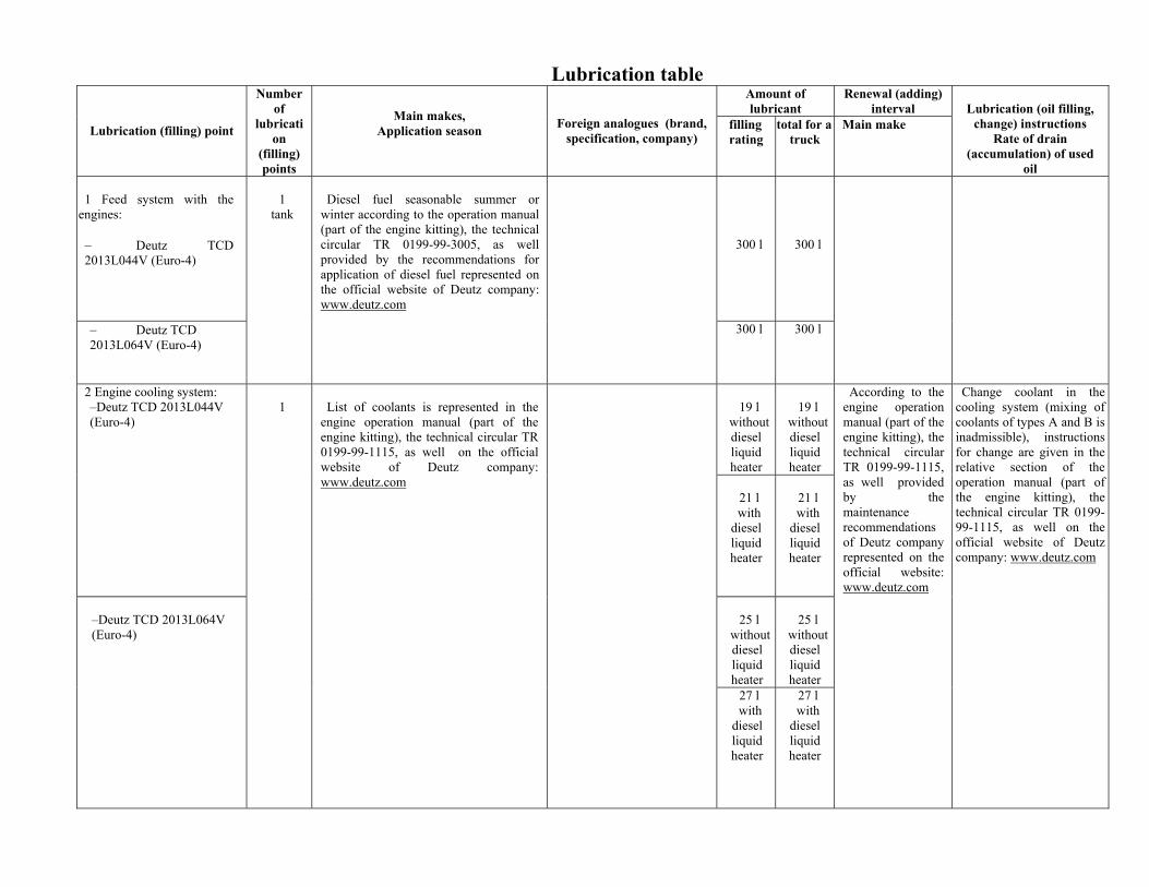
Lubrication table Amount of lubricant
Renewal (adding) interval
Lubrication (filling) point
Number of
lubrication
(filling) points
Main makes, Application season
Foreign analogues (brand, specification, company)
filling rating
total for a truck
Main make
Lubrication (oil filling,
change) instructions Rate of drain
(accumulation) of used oil
1 Feed system with the
engines: − Deutz TCD 2013L044V (Euro-4)
1
tank
300 l
300 l
− Deutz TCD 2013L064V (Еuro-4)
Diesel fuel seasonable summer or
winter according to the operation manual (part of the engine kitting), the technical circular TR 0199-99-3005, as well provided by the recommendations for application of diesel fuel represented on the official website of Deutz company: www.deutz.com
300 l 300 l
19 l
without diesel liquid heater
19 l
without diesel liquid heater
2 Engine cooling system: –Deutz TCD 2013L044V (Euro-4)
21 l with
diesel liquid heater
21 l with
diesel liquid heater
25 l
without diesel liquid heater
25 l
without diesel liquid heater
–Deutz TCD 2013L064V (Euro-4)
1
List of coolants is represented in the
engine operation manual (part of the engine kitting), the technical circular TR 0199-99-1115, as well on the official website of Deutz company: www.deutz.com
27 l with
diesel liquid heater
27 l with
diesel liquid heater
According to the engine operation manual (part of the engine kitting), the technical circular TR 0199-99-1115, as well provided by the maintenance recommendations of Deutz company represented on the official website: www.deutz.com
Change coolant in the cooling system (mixing of coolants of types А and В is inadmissible), instructions for change are given in the relative section of the operation manual (part of the engine kitting), the technical circular TR 0199-99-1115, as well on the official website of Deutz company: www.deutz.com
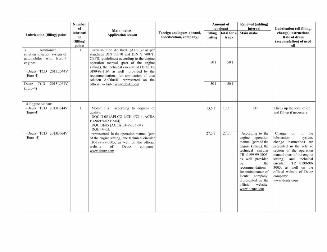
Amount of lubricant
Renewal (adding) interval
Lubrication (filling) point
Number of
lubrication
(filling) points
Main makes, Application season
Foreign analogues (brand, specification, company)
filling rating
total for a truck
Main make
Lubrication (oil filling,
change) instructions Rate of drain
(accumulation) of used oil
1
3 Ammoniac solution injection system of automobiles with Euro-4 engines –Deutz TCD 2013L044V (Euro-4)
50 l 50 l
Deutz TCD 2013L064V (Euro-4)
Urea solution AdBlue® (AUS 32 as per standards DIN 70070 and DIN V 70071, CEFIC guidelines) according to the engine operation manual (part of the engine kitting), the technical circular of Deutz TR 0199-99-1164, as well provided by the recommendations for application of urea solution AdBlue®, represented on the official website: www.deutz.com
50 l 50 l
4 Engine oil pan: –Deutz TCD 2013L044V (Euro-4)
1
13,5 l
13,5 l
ЕО
Check up the level of oil and fill up if necessary
–Deutz TCD 2013L064V (Euro -4)
Motor oils according to degrees of
quality: DQC II-05 (API CG-4/CH-4/CI-4, ACEA
E3-96/E5-02 E7-04) DQC III-05 (ACEA E4-99/E6-04) DQC IV-05, represented in the operation manual (part
of the engine kitting), the technical circular TR-199-99-3005, as well on the official website of Deutz company: www.deutz.com
27,5 l 27,5 l According to the engine operation manual (part of the engine kitting), the technical circular TR 0199-99-3005, as well provided by the recommendations for maintenance of Deutz company, represented on the official website: www.deutz.com
Change oil in the lubrication system, change instructions are presented in the relative section of the operation manual (part of the engine kitting) and technical circular TR 0199-99-3005, as well on the official website of Deutz company: www.deutz.com
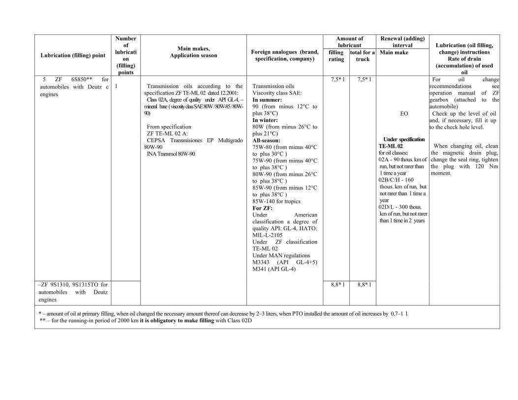
Amount of lubricant
Renewal (adding) interval
Lubrication (filling) point
Number of
lubrication
(filling) points
Main makes, Application season
Foreign analogues (brand, specification, company)
filling rating
total for a truck
Main make
Lubrication (oil filling,
change) instructions Rate of drain
(accumulation) of used oil
5 ZF 6S850** for automobiles with Deutz с engines
1
7,5* l 7,5* l For oil change recommendations see operation manual of ZF gearbox (attached to the automobile)
EO
Check up the level of oil and, if necessary, fill it up to the check hole level.
–ZF 9S1310, 9S1315TO for automobiles with Deutz engines
Transmission oils according to the
specification ZF TE-ML 02 dated 12.2001: Class 02А, degree of quality under API GL-4, –
mineral base ( viscosity class SAE 80W / 80W-85 / 80W-90) From specification ZF TE-ML 02 А: CEPSA Transmisiones EP Multigrado
80W-90 INA Transmol 80W-90
Transmission oils Viscosity class SAE: In summer: 90 (from minus 12°С to plus 38°С) In winter: 80W (from minus 26°С to plus 21°С) All-season: 75W-80 (from minus 40°С to plus 30°С ) 75W-90 (from minus 40°С to plus 38°С ) 80W-90 (from minus 26°С to plus 38°С ) 85W-90 (from minus 12°С to plus 38°С ) 85W-140 for tropics For ZF: Under American classification a degree of quality API: GL-4, НАТО: MIL-L-2105 Under ZF classification TE-ML 02 Under МАN regulations M3343 (API GL-4+5) М341 (API GL-4)
8,8* l 8,8* l
Under specification TE-ML 02 for oil classes: 02А - 90 thous. km of run, but not rarer than 1 time a year 02В/С/Н - 160 thous. km of run, but not rarer than 1 time a year 02D/L - 300 thous. km of run, but not rarer than 1 time in 2 years
When changing oil, clean
the magnetic drain plug, change the seal ring, tighten the plug with 120 Nm moment.
* – amount of oil at primary filling, when oil changed the necessary amount thereof can decrease by 2–3 liters, when PTO installed the amount of oil increases by 0,7–1 l. ** – for the running-in period of 2000 km it is obligatory to make filling with Class 02D
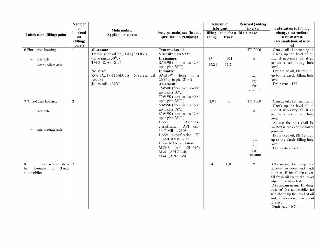
Amount of lubricant
Renewal (adding) interval
Lubrication (filling) point
Number of
lubrication
(filling) points
Main makes, Application season
Foreign analogues (brand, specification, company)
filling rating
total for a truck
Main make
Lubrication (oil filling,
change) instructions Rate of drain
(accumulation) of used oil
6 Final drive housing 1 ТО-2000
− rear axle 15 l 15 l А 15,2 l 15,2 l − intermediate axle
2С *С for
mixture
Change oil after running-in Check up the level of oil
and, if necessary, fill it up to the check filling hole level. Drain used oil, fill fresh oil
up to the check filling hole level. Drain rate – 12 l
7 Wheel gear housing 2 2,0 l 4,0 l ТО-2000
− rear axle А
− intermediate axle
2С *С for
mixture
Change oil after running-in Check up the level of oil
and, if necessary, fill it up to the check filling hole level. At that the hole shall be
located in the extreme lower position. Drain used oil, fill fresh oil
up to the check filling hole level. Drain rate – 3,6 l
8 Rear axle equalizer bar housing of 3-axle automobiles
2
All-season: Transmission oil ТАД17И (TAD17I) (up to minus 300С) ТМ-5-18, API GL-5 *Mixture: 85% ТАД17И (TAD17I) +15% diesel fuel
«А», «З» (below minus 300С)
Transmission oils Viscosity class SAE: In summer: SAE 90 (from minus 12°С up to plus 38°С) In winter: SAE80W (from minus 26°С up to plus 21°С) All-season: 75W-80 (from minus 40°С up to plus 30°С ) 75W-90 (from minus 40°С up to plus 38°С ) 80W-90 (from minus 26°С up to plus 38°С ) 85W-90 (from minus 12°С up to plus 38°С ) Under American classification API GL-3/4/5 MIL-L-2105 Under classification ZF TE-ML 02/05/07/12 Under МАN regulations M3343 (API GL-4+5) М341 (API GL-4), М342 (API GL-5)
0,4 l 0,8 2С Change oil, for doing this: remove the cover and wash it, drain oil, install the cover, fill fresh oil up to the lower edge of the filler hole. At running-in and handing-
over of the automobile for sale check up the level of oil and, if necessary, carry out refilling. Drain rate – 0,7 l
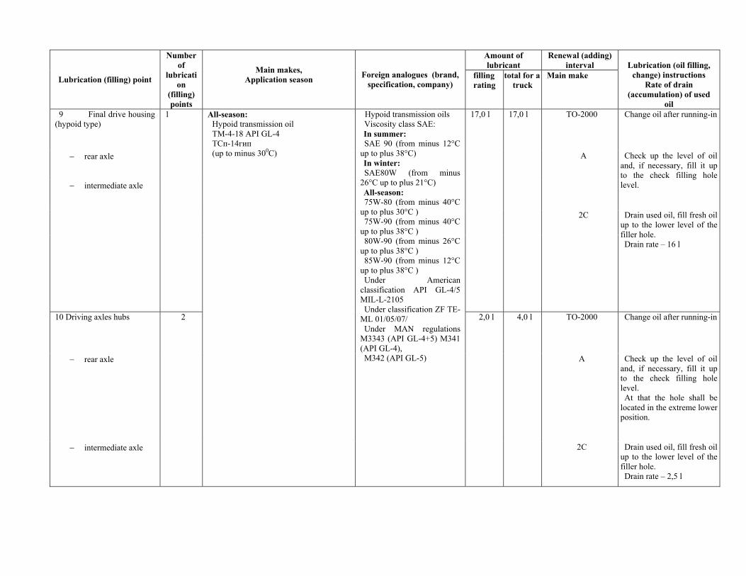
Amount of lubricant
Renewal (adding) interval
Lubrication (filling) point
Number of
lubrication
(filling) points
Main makes, Application season
Foreign analogues (brand, specification, company)
filling rating
total for a truck
Main make
Lubrication (oil filling,
change) instructions Rate of drain
(accumulation) of used oil
9 Final drive housing (hypoid type)
1 17,0 l 17,0 l ТО-2000 Change oil after running-in
− rear axle А
Check up the level of oil and, if necessary, fill it up to the check filling hole level.
2С
− intermediate axle
Drain used oil, fill fresh oil up to the lower level of the filler hole. Drain rate – 16 l
10 Driving axles hubs 2 2,0 l 4,0 l ТО-2000 Change oil after running-in
− rear axle А Check up the level of oil and, if necessary, fill it up to the check filling hole level. At that the hole shall be
located in the extreme lower position.
− intermediate axle
All-season: Hypoid transmission oil ТМ-4-18 API GL-4 ТСп-14гип (up to minus 300С)
Hypoid transmission oils Viscosity class SAE: In summer: SAE 90 (from minus 12°С
up to plus 38°С) In winter: SAE80W (from minus
26°С up to plus 21°С) All-season: 75W-80 (from minus 40°С
up to plus 30°С ) 75W-90 (from minus 40°С
up to plus 38°С ) 80W-90 (from minus 26°С
up to plus 38°С ) 85W-90 (from minus 12°С
up to plus 38°С ) Under American
classification API GL-4/5 MIL-L-2105 Under classification ZF TE-
ML 01/05/07/ Under МАN regulations
M3343 (API GL-4+5) М341 (API GL-4), М342 (API GL-5)
2С Drain used oil, fill fresh oil up to the lower level of the filler hole. Drain rate – 2,5 l
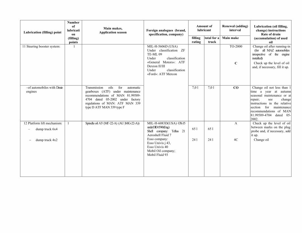
Amount of lubricant
Renewal (adding) interval Lubrication (filling) point
Number of
lubrication
(filling) points
Main makes, Application season
Foreign analogues (brand, specification, company)
filling rating
total for a truck
Main make
Lubrication (oil filling,
change) instructions Rate of drain
(accumulation) of used oil
11 Steering booster system: 1 ТО-2000 Change oil after running-in (for all MAZ automobiles
irrespective of the engine installed)
С Check up the level of oil and, if necessary, fill it up.
–of automobiles with Deutz engines
Transmission oils for automatic gearboxes (ATF) under maintenance recommendations of MAN 81.99589-4704 dated 05-2002 under factory regulations of МАN: ATF MAN 339 type D ATF MAN 339 type F
MIL-H-5606D (USA) Under classification ZF TE-ML 09 Under classification «General Motors»: ATF Dexron II/III Under classification «Ford»: ATF Mercon
7,0 l 7,0 l СО Change oil not less than 1 time a year at autumn seasonal maintenance or at repair; see change instructions in the relative section for maintenance recommendations of MAN 81.99589-4704 dated 05-2002.
12 Platform lift mechanism: 1 А
− dump truck 6х4 65 l 65 l Check up the level of oil
between marks on the plug probe and, if necessary, add it up.
− dump truck 4х2 24 l 24 l 4С Change oil
Spindle oil АУ (МГ-22-А) (AU )MG-22-A))
MIL-H-6083D(USA) OX-15 under DID-5540 (Eng.) Shell company: Tellus 21 Aeroshell Fluid 7 Esso company: Esso Univis j 43, Esso Univis 40 Mobil Oil company; Mobil Fluid 93
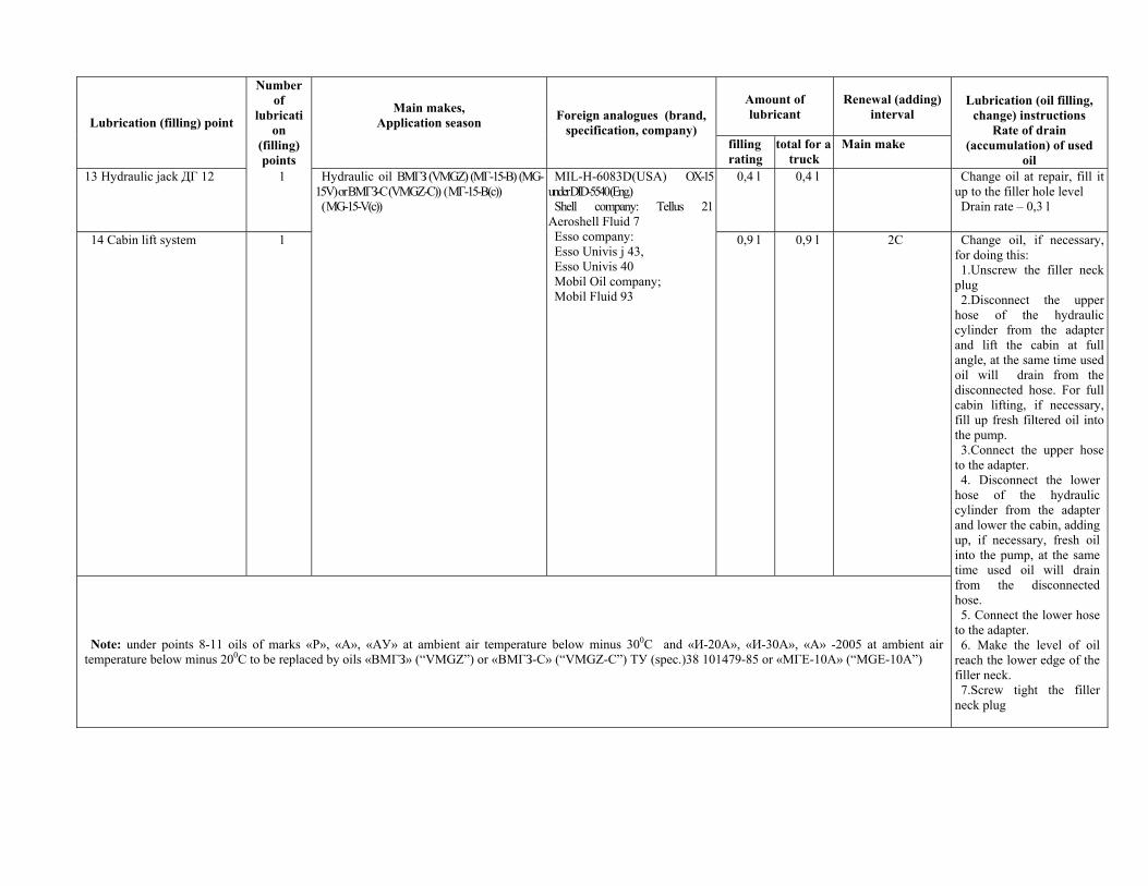
Amount of lubricant
Renewal (adding) interval Lubrication (filling) point
Number of
lubrication
(filling) points
Main makes, Application season
Foreign analogues (brand, specification, company)
filling rating
total for a truck
Main make
Lubrication (oil filling,
change) instructions Rate of drain
(accumulation) of used oil
13 Hydraulic jack ДГ 12 1 0,4 l 0,4 l Change oil at repair, fill it up to the filler hole level Drain rate – 0,3 l
14 Cabin lift system 1
Hydraulic oil ВМГЗ (VMGZ) (МГ-15-В) (MG-15V) or ВМГЗ-С (VMGZ-C)) ( МГ-15-В(с)) ( МG-15-V(с))
MIL-H-6083D(USA) OX-15 under DID-5540 (Eng.) Shell company: Tellus 21
Aeroshell Fluid 7 Esso company: Esso Univis j 43, Esso Univis 40 Mobil Oil company; Mobil Fluid 93
0,9 l 0,9 l 2С
Note: under points 8-11 oils of marks «Р», «А», «АУ» at ambient air temperature below minus 300С and «И-20А», «И-30А», «А» -2005 at ambient air temperature below minus 200С to be replaced by oils «ВМГЗ» (“VMGZ”) or «ВМГЗ-С» (“VMGZ-C”) ТУ (spec.)38 101479-85 or «МГЕ-10А» (“MGE-10A”)
Change oil, if necessary, for doing this: 1.Unscrew the filler neck
plug 2.Disconnect the upper
hose of the hydraulic cylinder from the adapter and lift the cabin at full angle, at the same time used oil will drain from the disconnected hose. For full cabin lifting, if necessary, fill up fresh filtered oil into the pump. 3.Connect the upper hose
to the adapter. 4. Disconnect the lower
hose of the hydraulic cylinder from the adapter and lower the cabin, adding up, if necessary, fresh oil into the pump, at the same time used oil will drain from the disconnected hose. 5. Connect the lower hose
to the adapter. 6. Make the level of oil
reach the lower edge of the filler neck. 7.Screw tight the filler
neck plug
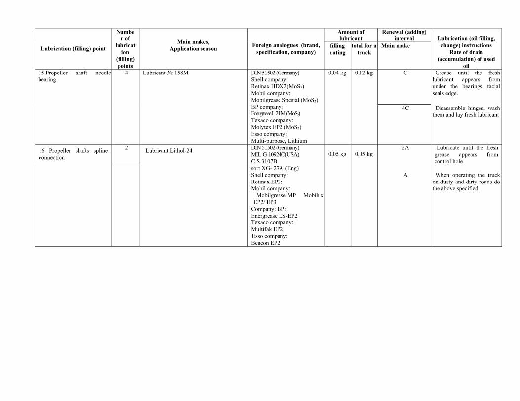
Amount of lubricant
Renewal (adding) interval
Lubrication (filling) point
Number of
lubrication
(filling) points
Main makes, Application season
Foreign analogues (brand, specification, company)
filling rating
total for a truck
Main make
Lubrication (oil filling,
change) instructions Rate of drain
(accumulation) of used oil
С Grease until the fresh lubricant appears from under the bearings facial seals edge.
15 Propeller shaft needle bearing
4 Lubricant № 158М
DIN 51502 (Germany) Shell company: Retinax HDX2(МоS2) Mobil company: Mobilgrease Spesial (МоS2) BP company: Energrease L 21 M (МоS2) Texaco company: Molytex EP2 (МоS2) Esso company: Multi-purpose, Lithium
0,04 kg 0,12 kg
4С Disassemble hinges, wash them and lay fresh lubricant
16 Propeller shafts spline connection
2 Lubricant Lithol-24 0,05 kg 0,05 kg
DIN 51502 (Germany) MIL-G-10924C(USA) C.S.3107B sort XG- 279, (Eng) Shell company: Retinax EP2; Mobil company:
Mobilgrease MP MobiluxEP2/ EP3
Company: BP: Energrease LS-EP2 Texaco company: Multifak EP2 Esso company: Beacon EP2
2А А
Lubricate until the fresh grease appears from control hole. When operating the truck
on dusty and dirty roads do the above specified.
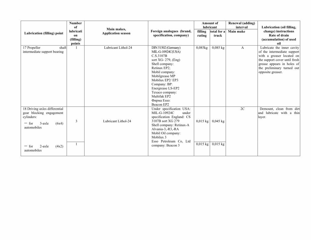
Amount of lubricant
Renewal (adding) interval
Lubrication (filling) point
Number of
lubrication
(filling) points
Main makes, Application season
Foreign analogues (brand, specification, company)
filling rating
total for a truck
Main make
Lubrication (oil filling,
change) instructions Rate of drain
(accumulation) of used oil
17 Propeller shaft intermediate support bearing
1 Lubricant Lithol-24 DIN 51502 (Germany) MIL-G-10924C(USA) C.S.3107B sort XG- 279, (Eng) Shell company: Retinax EP2; Mobil company: Mobilgrease MP Mobilux EP2/ EP3 Company: BP: Energrease LS-EP2 Texaco company: Multifak EP2 Фирмa Esso: Beacon EP2
0,085kg 0,085 kg А Lubricate the inner cavity of the intermediate support with a greaser located on the support cover until fresh grease appears in holes of the preliminary turned out opposite greaser.
18 Driving axles differential gear blocking engagement cylinders:
2С
− for 3-axle (6х4) automobiles
3 Lubricant Lithol-24 0,015 kg 0,045 kg
− for 2-axle (4х2) automobiles
1
Under specification USA: MIL-G-10924C under specification England: CS 3107B sort XG 279 Shell company: Retinax-A Alvania-3,-R3,-RA Mobil Oil company: Mobilux 3 Esso Petroleum Co, Ltd company: Beacon 3 0,015 kg 0,015 kg
Demount, clean from dirt and lubricate with a thin layer.
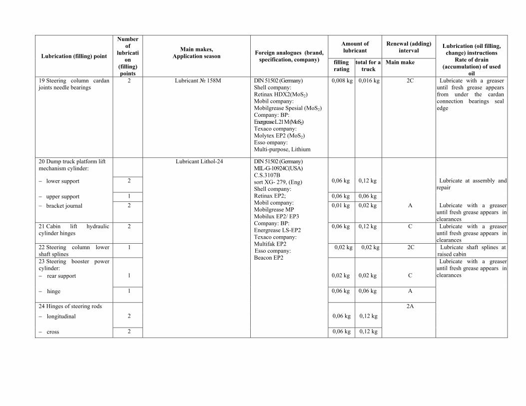
Amount of lubricant
Renewal (adding) interval
Lubrication (filling) point
Number of
lubrication
(filling) points
Main makes, Application season
Foreign analogues (brand, specification, company) filling
rating total for a
truck Main make
Lubrication (oil filling,
change) instructions Rate of drain
(accumulation) of used oil
19 Steering column cardan joints needle bearings
2 Lubricant № 158М
DIN 51502 (Germany) Shell company: Retinax HDX2(МоS2) Mobil company: Mobilgrease Spesial (МоS2) Company: BP: Energrease L 21 M (МоS2) Texaco company: Molytex EP2 (МоS2) Esso ompany: Multi-purpose, Lithium
0,008 kg 0,016 kg 2С Lubricate with a greaser until fresh grease appears from under the cardan connection bearings seal edge
20 Dump truck platform lift mechanism cylinder:
− lower support 2 0,06 kg 0,12 kg Lubricate at assembly and repair
− upper support 1 0,06 kg 0,06 kg − bracket journal 2 0,01 kg 0,02 kg A Lubricate with a greaser
until fresh grease appears in clearances
21 Cabin lift hydraulic cylinder hinges
2 0,06 kg 0,12 kg C Lubricate with a greaser until fresh grease appears in clearances
22 Steering column lower shaft splines
1 0,02 kg 0,02 kg 2C Lubricate shaft splines at raised cabin
23 Steering booster power cylinder:
− rear support 1 0,02 kg 0,02 kg C
Lubricate with a greaser until fresh grease appears in clearances
− hinge 1 0,06 kg 0,06 kg A
24 Hinges of steering rods 2A
− longitudinal 2 0,06 kg 0,12 kg
− cross 2
Lubricant Lithol-24
DIN 51502 (Germany) MIL-G-10924C(USA) C.S.3107B sort XG- 279, (Eng) Shell company: Retinax EP2; Mobil company: Mobilgrease MP Mobilux EP2/ EP3 Company: BP: Energrease LS-EP2 Texaco company: Multifak EP2 Esso company: Beacon EP2
0,06 kg 0,12 kg
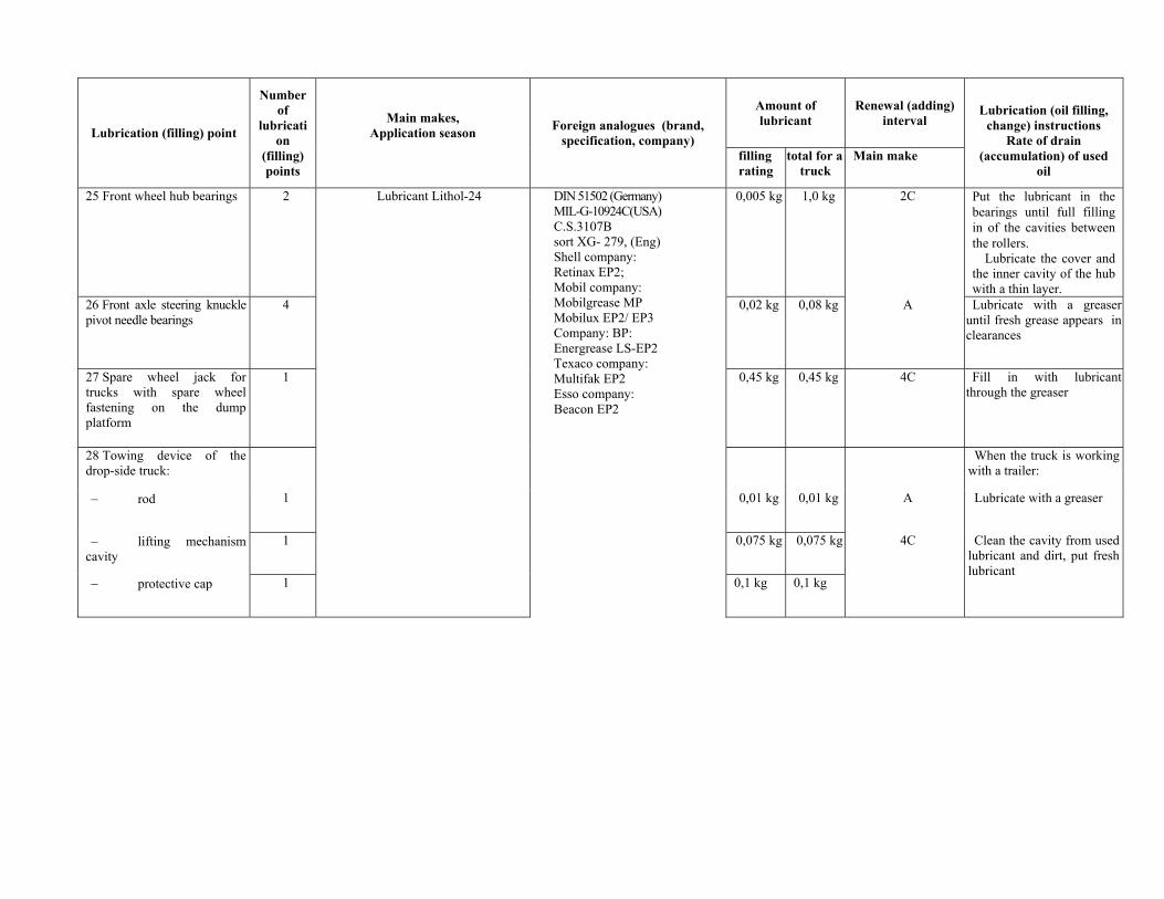
Amount of lubricant
Renewal (adding) interval
Lubrication (filling) point
Number of
lubrication
(filling) points
Main makes, Application season
Foreign analogues (brand, specification, company)
filling rating
total for a truck
Main make
Lubrication (oil filling,
change) instructions Rate of drain
(accumulation) of used oil
25 Front wheel hub bearings 2 0,005 kg 1,0 kg 2С Put the lubricant in the bearings until full filling in of the cavities between the rollers.
Lubricate the cover and the inner cavity of the hub with a thin layer.
26 Front axle steering knuckle pivot needle bearings
4 0,02 kg 0,08 kg А Lubricate with a greaser until fresh grease appears in clearances
27 Spare wheel jack for trucks with spare wheel fastening on the dump platform
1 0,45 kg 0,45 kg 4С Fill in with lubricant through the greaser
28 Towing device of the drop-side truck:
When the truck is working with a trailer:
− rod 1 0,01 kg 0,01 kg А Lubricate with a greaser
− lifting mechanism cavity
1 0,075 kg 0,075 kg
− protective cap 1
Lubricant Lithol-24
DIN 51502 (Germany) MIL-G-10924C(USA) C.S.3107B sort XG- 279, (Eng) Shell company: Retinax EP2; Mobil company: Mobilgrease MP Mobilux EP2/ EP3 Company: BP: Energrease LS-EP2 Texaco company: Multifak EP2 Esso company: Beacon EP2
0,1 kg 0,1 kg
4С Clean the cavity from used lubricant and dirt, put fresh lubricant
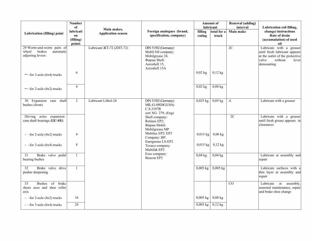
Amount of lubricant
Renewal (adding) interval
Lubrication (filling) point
Number of
lubrication
(filling) points
Main makes, Application season
Foreign analogues (brand, specification, company)
filling rating
total for a truck
Main make
Lubrication (oil filling,
change) instructions Rate of drain
(accumulation) of used oil
29 Worm-and-worm pairs of wheel brakes automatic adjusting levers:
2C
− –for 3-axle (6х4) trucks 6 0,02 kg 0,12 kg
− –for 2-axle (4х2) trucks 4
Lubricant ЖТ-72 (ZHT-72)
DIN 51502 (Germany) Mobil Oil company: Mobilgrease 24, Фирма Shell: Aeroshell 15, Aeroshell 15А
0,02 kg 0,08 kg
Lubricate with a greaser until fresh lubricant appears at the outlet of the protective valve without lever demounting
30 Expansion cam shaft bushes (front)
2 0,025 kg 0,05 kg A Lubricate with a greaser
Driving axles expansion cam shaft bearings (ШС-40К):
2C
− –for 2-axle (4х2) trucks 4 0,015 kg 0,06 kg
− –for 3-axle (6х4) trucks 8 0,015 kg 0,12 kg
Lubricate with a greaser until fresh grease appears in clearances
31 Brake valve pedal bearing bushes
1 0,04 kg 0,04 kg Lubricate at assembly and repair
32 Brake valve drive pusher deepening
1
Lubricant Lithol-24 DIN 51502 (Germany) MIL-G-10924C(USA) C.S.3107B sort XG- 279, (Eng) Shell company: Retinax EP2; Фирма Mobil: Mobilgrease MP Mobilux EP2/ EP3 Company: BP: Energrease LS-EP2 Texaco company: Multifak EP2 Esso company: Beacon EP2
0,005 kg 0,005 kg Lubricate surfaces with a thin layer at assembly and repair
33 Bushes of brake shoes axes and shoe roller axis
СО Lubricate at assembly, seasonal maintenance, repair and brake shoe change
− –for 2-axle (4х2) trucks 16 0,005 kg 0,08 kg
− –for 3-axle (6х4) trucks 24 0,005 kg 0,12 kg
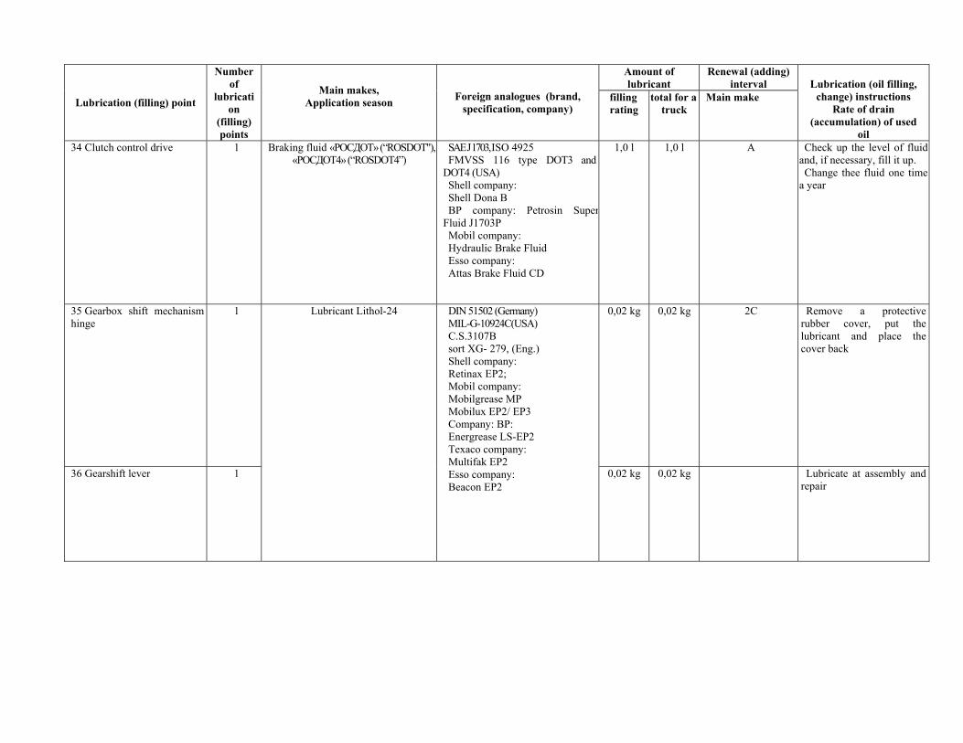
Amount of lubricant
Renewal (adding) interval
Lubrication (filling) point
Number of
lubrication
(filling) points
Main makes, Application season
Foreign analogues (brand, specification, company)
filling rating
total for a truck
Main make
Lubrication (oil filling,
change) instructions Rate of drain
(accumulation) of used oil
34 Clutch control drive 1 Braking fluid «РОСДОТ» (“ROSDOT"), «РОСДОТ4» (“ROSDOT4”)
SAE J 1703, ISO 4925 FMVSS 116 type DOT3 and
DOT4 (USA) Shell company: Shell Dona B ВР company: Petrosin Super
Fluid J1703P Mobil company: Hydraulic Brake Fluid Esso company: Attas Brake Fluid CD
1,0 l 1,0 l A
Check up the level of fluid and, if necessary, fill it up. Change thee fluid one time
a year
35 Gearbox shift mechanism hinge
1 0,02 kg 0,02 kg 2C
Remove a protective rubber cover, put the lubricant and place the cover back
36 Gearshift lever 1
Lubricant Lithol-24 DIN 51502 (Germany) MIL-G-10924C(USA) C.S.3107B sort XG- 279, (Eng.) Shell company: Retinax EP2; Mobil company: Mobilgrease MP Mobilux EP2/ EP3 Company: BP: Energrease LS-EP2 Texaco company: Multifak EP2 Esso company: Beacon EP2
0,02 kg 0,02 kg Lubricate at assembly and repair
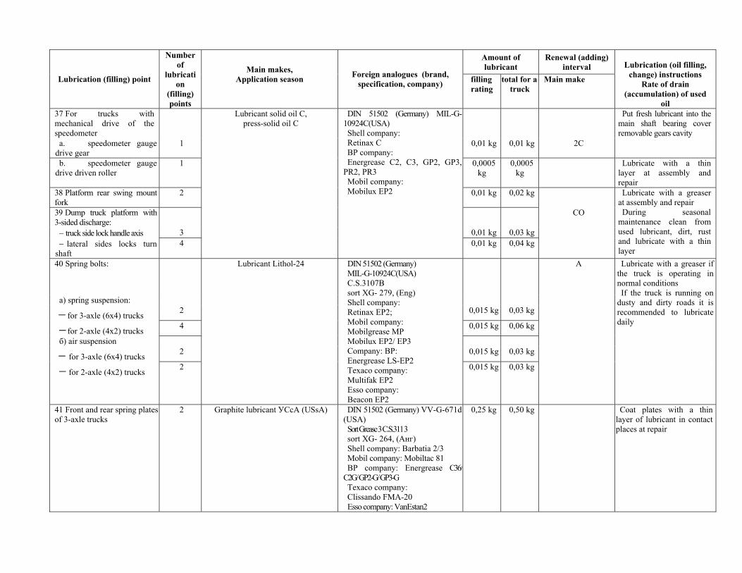
Amount of lubricant
Renewal (adding) interval
Lubrication (filling) point
Number of
lubrication
(filling) points
Main makes, Application season
Foreign analogues (brand, specification, company) filling
rating total for a
truck Main make
Lubrication (oil filling,
change) instructions Rate of drain
(accumulation) of used oil
37 For trucks with mechanical drive of the speedometer
a. speedometer gauge drive gear
1 0,01 kg 0,01 kg 2C
Put fresh lubricant into the main shaft bearing cover removable gears cavity
b. speedometer gauge drive driven roller
1
Lubricant solid oil С, press-solid oil С
0,0005 kg
0,0005 kg
Lubricate with a thin layer at assembly and repair
38 Platform rear swing mount fork
2 0,01 kg 0,02 kg
39 Dump truck platform with 3-sided discharge:
СО
− truck side lock handle axis 3 0,01 kg 0,03 kg − lateral sides locks turn
shaft 4
DIN 51502 (Germany) MIL-G-10924C(USA) Shell company: Retinax C BP company: Energrease C2, C3, GP2, GP3,
PR2, PR3 Mobil company: Mobilux EP2
0,01 kg 0,04 kg
Lubricate with a greaser at assembly and repair During seasonal
maintenance clean from used lubricant, dirt, rust and lubricate with a thin layer
40 Spring bolts:
а) spring suspension:
− for 3-axle (6х4) trucks 2 0,015 kg 0,03 kg
− for 2-axle (4х2) trucks 4 0,015 kg 0,06 kg
б) air suspension
− for 3-axle (6х4) trucks 2 0,015 kg 0,03 kg
− for 2-axle (4х2) trucks 2
Lubricant Lithol-24 DIN 51502 (Germany) MIL-G-10924C(USA) C.S.3107B sort XG- 279, (Eng) Shell company: Retinax EP2; Mobil company: Mobilgrease MP Mobilux EP2/ EP3 Company: BP: Energrease LS-EP2 Texaco company: Multifak EP2 Esso company: Beacon EP2
0,015 kg 0,03 kg
A Lubricate with a greaser if the truck is operating in normal conditions If the truck is running on
dusty and dirty roads it is recommended to lubricate daily
41 Front and rear spring plates of 3-axle trucks
2 Graphite lubricant УСсА (USsA) DIN 51502 (Germany) VV-G-671d (USA) Sort Grease 3 C.S.3113 sort XG- 264, (Анг) Shell company: Barbatia 2/3 Mobil company: Mobiltac 81 BP company: Energrease С36/ С2G/ GP2-G/ GP3-G Texaco company: Clissando FMA-20 Esso company: VanEstan2
0,25 kg 0,50 kg Coat plates with a thin layer of lubricant in contact places at repair
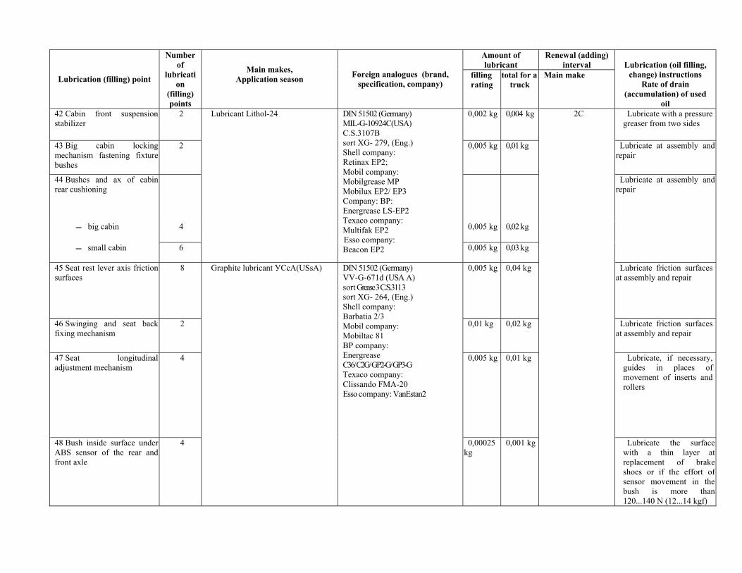
Amount of lubricant
Renewal (adding) interval
Lubrication (filling) point
Number of
lubrication
(filling) points
Main makes, Application season
Foreign analogues (brand, specification, company)
filling rating
total for a truck
Main make
Lubrication (oil filling,
change) instructions Rate of drain
(accumulation) of used oil
42 Cabin front suspension stabilizer
2 0,002 kg 0,004 kg 2С Lubricate with a pressure greaser from two sides
43 Big cabin locking mechanism fastening fixture bushes
2
Lubricant Lithol-24
0,005 kg 0,01 kg Lubricate at assembly and repair
44 Bushes and ax of cabin rear cushioning
Lubricate at assembly and repair
big cabin 4 0,005 kg 0,02 kg
small cabin 6
DIN 51502 (Germany) MIL-G-10924C(USA) C.S.3107B sort XG- 279, (Eng.) Shell company: Retinax EP2; Mobil company: Mobilgrease MP Mobilux EP2/ EP3 Company: BP: Energrease LS-EP2 Texaco company: Multifak EP2 Esso company: Beacon EP2 0,005 kg 0,03 kg
45 Seat rest lever axis friction surfaces
8 0,005 kg 0,04 kg Lubricate friction surfaces at assembly and repair
46 Swinging and seat back fixing mechanism
2 0,01 kg 0,02 kg Lubricate friction surfaces at assembly and repair
47 Seat longitudinal adjustment mechanism
4 0,005 kg 0,01 kg Lubricate, if necessary, guides in places of movement of inserts and rollers
48 Bush inside surface under ABS sensor of the rear and front axle
4
Graphite lubricant УСсА(USsA) DIN 51502 (Germany) VV-G-671d (USA А) sort Grease 3 C.S.3113 sort XG- 264, (Eng.) Shell company: Barbatia 2/3 Mobil company: Mobiltac 81 BP company: Energrease С36/ С2G/ GP2-G/ GP3-G Texaco company: Clissando FMA-20 Esso company: VanEstan2
0,00025 kg
0,001 kg
Lubricate the surface with a thin layer at replacement of brake shoes or if the effort of sensor movement in the bush is more than 120...140 N (12...14 kgf)
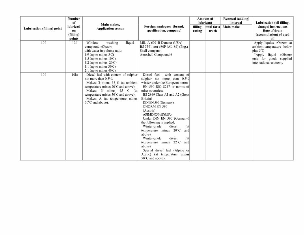
Amount of lubricant
Renewal (adding) interval
Lubrication (filling) point
Number of
lubrication
(filling) points
Main makes, Application season
Foreign analogues (brand, specification, company)
filling rating
total for a truck
Main make
Lubrication (oil filling,
change) instructions Rate of drain
(accumulation) of used oil
10 l 10 l Window washing liquid compound «Obzor» with water in volume ratio: 1:9 (up to minus 5 С) 1:5 (up to minus 10 С) 1:2 (up to minus 20 С) 1:1 (up to minus 30 С) 2:1 (up to minus 40 С)
MIL-A-6091B Denatur (USA) BS 3591 sort 680P (AL-8d) (Eng.) Shell company: Aeroshell Compound 6
Apply liquids «Obzor» at ambient temperature below plus 50С *Apply liquid «Obzor»
only for goods supplied into national economy
10 l 10lл Diesel fuel with content of sulphur not more than 0,5%. Makes: З minus 35 С (at ambient
temperature minus 200С and above). Makes: З minus 45 С (at
temperature minus 300С and above). Makes: А (at temperature minus
500С and above).
Diesel fuel with content of sulphur not more than 0,5% winter under the European norm: EN 590 ISO 8217 or norms of
other countries: BS 2869 Class A1 and A2 (Great
Britain) DIN EN 590 (Germany) ONORM EN 590 (Austria) ASTM D 975 N01D (USA) Under DIN EN 590 (Germany)
the following is applied: Winter-grade diesel (at
temperature minus 20°С and above) Winter-grade diesel (at
temperature minus 22°С and above) Special diesel fuel (Alpine or
Arctic) (at temperature minus 50°С and above)
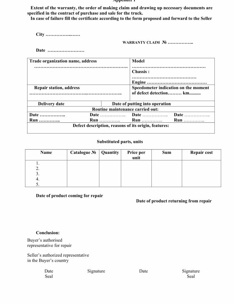
Appendix 1
Extent of the warranty, the order of making claim and drawing up necessary documents are specified in the contract of purchase and sale for the truck.
In case of failure fill the certificate according to the form proposed and forward to the Seller City ……………..……
WARRANTY CLAIM № ……………..
Date ……………………
Trade organization name, address …………………………………………………….
Model ………………………………………… Chassis : …………………………………… Engine …………………………………
Repair station, address ………………………………..…………………..
Speedometer indication on the moment of defect detection……… km..........
Delivery date Date of putting into operation Routine maintenance carried out:
Date …………….. Run …………..
Date …………….. Run …………..
Date …………….. Run …………..
Date …………….. Run …………..
Defect description, reasons of its origin, features:
Substituted parts, units
Name Catalogue №
Quantity Price per
unit Sum Repair cost
1. 2. 3. 4. 5.
Date of product coming for repair
Date of product returning from repair
Conclusion:
Buyer’s authorised representative for repair Seller’s authorized representative in the Buyer’s country
Date Signature Date Signature Seal Seal
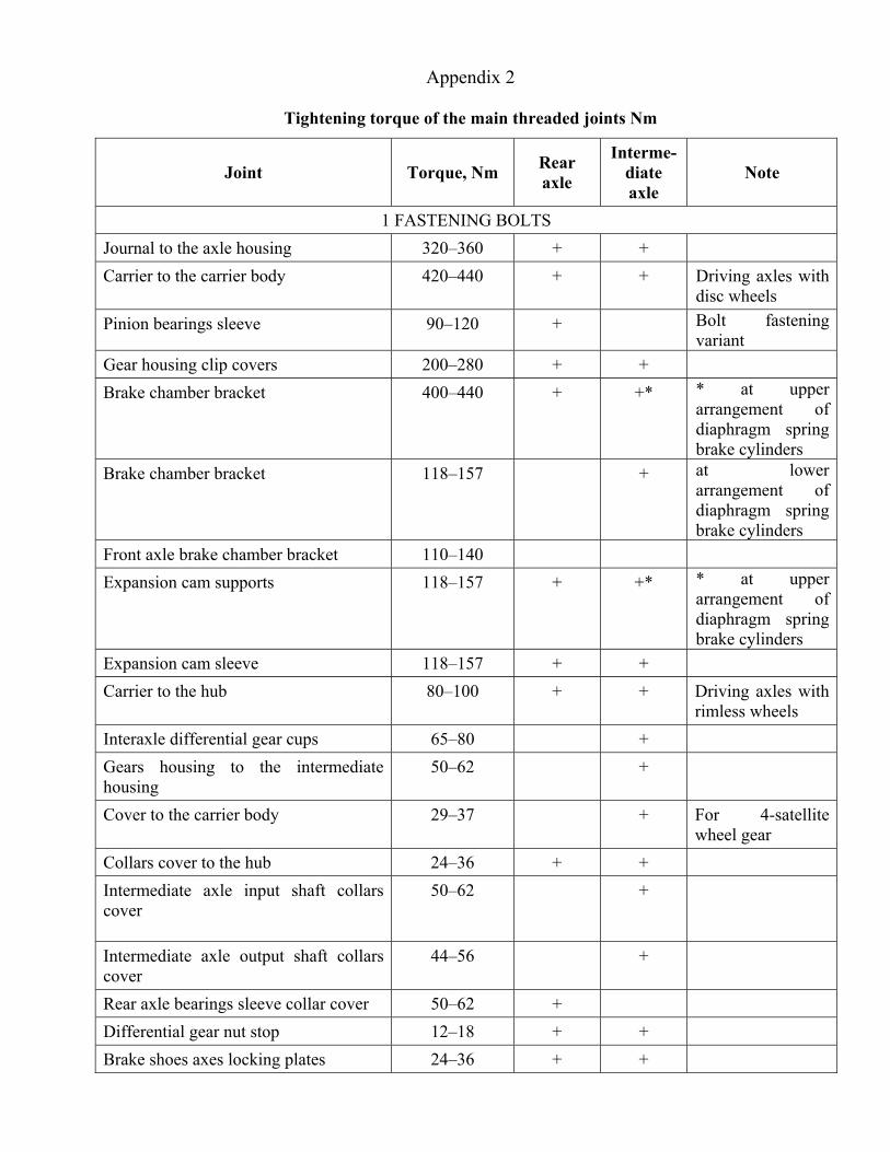
Appendix 2
Tightening torque of the main threaded joints Nm
Joint Torque, Nm Rear axle
Interme-diate axle
Note
1 FASTENING BOLTS Journal to the axle housing 320–360 + + Carrier to the carrier body 420–440 + + Driving axles with
disc wheels Pinion bearings sleeve 90–120 + Bolt fastening
variant Gear housing clip covers 200–280 + + Brake chamber bracket 400–440 + +* * at upper
arrangement of diaphragm spring brake cylinders
Brake chamber bracket 118–157 + at lower arrangement of diaphragm spring brake cylinders
Front axle brake chamber bracket 110–140 Expansion cam supports 118–157 + +* * at upper
arrangement of diaphragm spring brake cylinders
Expansion cam sleeve 118–157 + + Carrier to the hub 80–100 + + Driving axles with
rimless wheels Interaxle differential gear cups 65–80 + Gears housing to the intermediate housing
50–62 +
Cover to the carrier body 29–37 + For 4-satellite wheel gear
Collars cover to the hub 24–36 + + Intermediate axle input shaft collars cover
50–62 +
Intermediate axle output shaft collars cover
44–56 +
Rear axle bearings sleeve collar cover 50–62 + Differential gear nut stop 12–18 + + Brake shoes axes locking plates 24–36 + +
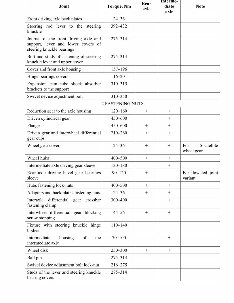
Joint Torque, Nm Rear axle
Interme-diate axle
Note
Front driving axle back plates 24–36 Steering rod lever to the steering knuckle
392–432
Journal of the front driving axle and support, lever and lower covers of steering knuckle bearings
275–314
Bolt and studs of fastening of steering knuckle lever and upper cover
275–314
Cover and front axle housing 157–196 Hinge bearings covers 16–20 Expansion cam tube shock absorber brackets to the support
310–315
Swivel device adjustment bolt 310–350 2 FASTENING NUTS
Reduction gear to the axle housing 120–160 + + Driven cylindrical gear 450–600 + Flanges 450–600 + + Driven gear and interwheel differential gear cups
210–260 + +
Wheel gear covers 24–36 + + For 5-satellite wheel gear
Wheel hubs 400–500 + + Intermediate axle driving gear sleeve 130–180 + Rear axle driving bevel gear bearings sleeve
90–120 + For doweled joint variant
Hubs fastening lock-nuts 400–500 + + Adapters and back plates fastening nuts 24–36 + + Interaxle differential gear crossbar fastening clamp
300–400 +
Interwheel differential gear blocking screw stopping
44–56 + +
Fixture with steering knuckle hinge bodies
110–140
Intermediate housing of the intermediate axle
70–100 +
Wheel disk 250–300 + + Ball pin 275–314 Swivel device adjustment bolt lock-nut 216–275 Studs of the lever and steering knuckle bearing covers
275–314
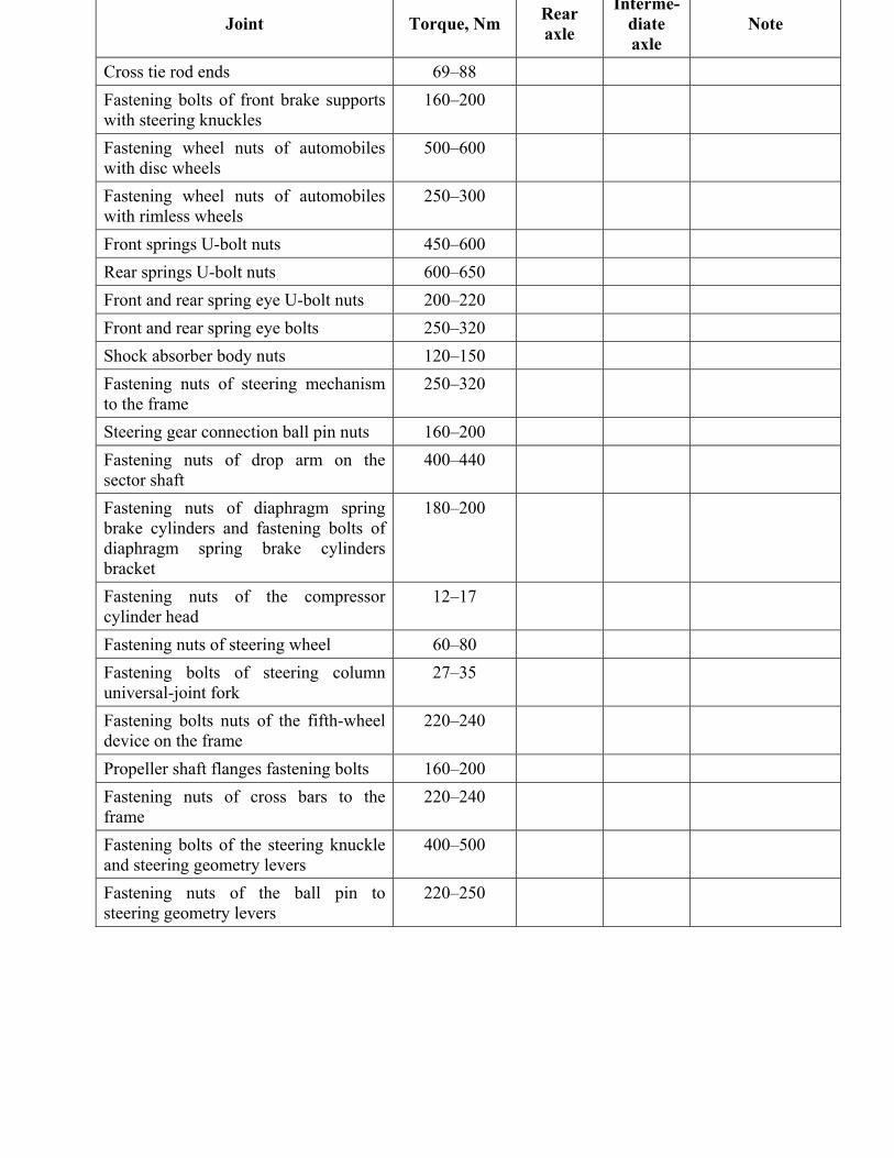
Joint Torque, Nm Rear axle
Interme-diate axle
Note
Cross tie rod ends 69–88 Fastening bolts of front brake supports with steering knuckles
160–200
Fastening wheel nuts of automobiles with disc wheels
500–600
Fastening wheel nuts of automobiles with rimless wheels
250–300
Front springs U-bolt nuts 450–600 Rear springs U-bolt nuts 600–650 Front and rear spring eye U-bolt nuts 200–220 Front and rear spring eye bolts 250–320 Shock absorber body nuts 120–150 Fastening nuts of steering mechanism to the frame
250–320
Steering gear connection ball pin nuts 160–200 Fastening nuts of drop arm on the sector shaft
400–440
Fastening nuts of diaphragm spring brake cylinders and fastening bolts of diaphragm spring brake cylinders bracket
180–200
Fastening nuts of the compressor cylinder head
12–17
Fastening nuts of steering wheel 60–80 Fastening bolts of steering column universal-joint fork
27–35
Fastening bolts nuts of the fifth-wheel device on the frame
220–240
Propeller shaft flanges fastening bolts 160–200 Fastening nuts of cross bars to the frame
220–240
Fastening bolts of the steering knuckle and steering geometry levers
400–500
Fastening nuts of the ball pin to steering geometry levers
220–250
CONTENTS
Page
Introduction ………………………………………………………………..
Safety requirements and caution ……………………….
Technical data ………………………………………….
Controls and instrumentation ……….
Cabin accessories ………………………………………………
Pre-sale preparation works list ……….
Running in of the truck ……………………………………………………
Truck operation peculiarities ………………………………
Preparation of the truck for operation ………………………………
Driving the truck and monitoring of its system and units operation ………..
Tires mounting and dismounting………………………………………………
Securing spare wheel …………………………………………
Adjustments ……………………………………………….
Maintenance of the truck ….……………………………
Appendices ……………………………………………………………...


