This document provides performance requirements for ATM surveillance system when supporting 3 and 5 NM horizontal separation applications. This specification has been developed by an international group of experts from air navigation service providers, system manufacturers and national supervisory authorities. This document can be used by air navigation service providers to define, as required by Commission Implementing Regulation (EU) No 1207/2011 of 22 November 2011, the minimum performance that their surveillance system must meet. This specification also defines how the associated conformity assessment must be performed.
Keywords Surveillance ATM Specification Performance Horizontal separation Quality of service Data item SES
Contact Persons Tel Unit Eric POTIER +32 (0) 27294741 NMD/NS/SCC
Michel BORELY +32 (0) 27291161 DPS/TEC
STATUS, AUDIENCE AND ACCESSIBILITY Status Intended for Accessible via
Working Draft General Public Intranet Draft EUROCONTROL Extranet Proposed Issue Restricted Internet (www.eurocontrol.int) Released Issue
EUROCONTROL Specification for ATM Surveillance System Performance (Volume 2 Appendices)
Edition Number: 1.1 Released Issue Page 3
DOCUMENT APPROVAL
See Volume 1
EUROCONTROL Specification for ATM Surveillance System Performance (Volume 2 Appendices)
Page 4 Released Issue Edition: 1.1
DOCUMENT CHANGE RECORD
See Volume 1
Publications EUROCONTROL Headquarters 96 Rue de la Fusée B-1130 BRUSSELS Tel: +32 (0)2 729 4715 Fax: +32 (0)2 729 5149 E-mail: [email protected]
EUROCONTROL Specification for ATM Surveillance System Performance (Volume 2 Appendices)
Edition Number: 1.1 Released Issue Page 5
CONTENTS
Appendix - I Justifications of the specified performance metrics ................ 11 I - 1 Approaches for defining performance requirement criteria .....................................................11 I - 2 An example of top-down approach to define performance requirement criteria .....................11 I - 3 Measurement interval ..............................................................................................................11 I - 4 Probability of update of horizontal position .............................................................................12 I - 5 Ratio of missed reports involved in long gaps ........................................................................13 I - 6 RMS error of horizontal position .............................................................................................14 I - 7 Ratio of target reports involved in sets of consecutive correlated horizontal position
errors .......................................................................................................................................15 I - 8 Relative time of applicability of close horizontal positions ......................................................15 I - 9 Data age and ratio of incorrect pressure altitude ....................................................................16 I - 10 Unsigned error of pressure altitude .........................................................................................18 I - 11 Delay of transmission of SPI and emergency indicators ........................................................18 I - 12 Delay of transmission of change of aircraft identity ................................................................18 I - 13 Probability of update of correct aircraft identity .......................................................................18 I - 14 Ratio of incorrect aircraft identity ............................................................................................19 I - 15 RMS errors of rate of climb/descent .......................................................................................19 I - 16 RMS errors of track velocity vector components ....................................................................19 I - 17 Density of uncorrelated false target reports ............................................................................20 I - 18 Number of falsely confirmed tracks close to true tracks .........................................................21
Appendix - II Traceability and justification matrix ........................................... 23 II - 1 Conventions ............................................................................................................................23 II - 2 Traceability, justification and links to equivalent requirement statement ................................24
Appendix - III Air traffic services ...................................................................... 111
Appendix - IV Conformity assessment of specific designs ........................... 113 IV - 1 SSR Mono radar system design based on [RD 2] ................................................................114 IV - 2 Mode S mono radar system design based on [RD 3] ...........................................................120 IV - 3 Single ADS-B ground station based on [RD 14] (ADS-B NRA) ............................................126 IV - 4 Single ADS-B ground station based on [RD 15] (ADS-B RAD) ............................................132 IV - 5 Wide Area Multilateration system based on [RD 16] ............................................................138 IV - 6 System design including tracker ...........................................................................................142
Appendix - V Detailed description of the Operational Performance Assessment scenarios .......................................................................................... 143
EUROCONTROL Specification for ATM Surveillance System Performance (Volume 2 Appendices)
Page 6 Released Issue Edition: 1.1
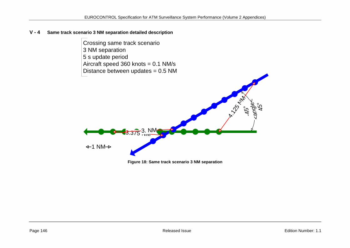
V - 3 Same track scenario 5 NM separation detailed description ..................................................145 V - 4 Same track scenario 3 NM separation detailed description ..................................................146 V - 5 Reciprocal track scenario 5 NM separation detailed description ..........................................147 V - 6 Reciprocal track scenario 3 NM separation detailed description ..........................................148 V - 7 Vertical crossing track scenario 5 NM separation detailed descriptions ...............................149 V - 8 Vertical crossing track scenario 3 NM separation detailed descriptions ...............................151
Appendix - VI An approach to justify requirements based on the model described in [RD 22] and in [RD 18] ......................................................... 153
VI - 1 Introduction ...........................................................................................................................153 VI - 2 Generalities ...........................................................................................................................153 VI - 3 Model parameters and model results for 5 NM separation ...................................................155 VI - 4 Model parameters and model results for 3 NM separation ...................................................158
EUROCONTROL Specification for ATM Surveillance System Performance (Volume 2 Appendices)
Edition Number: 1.1 Released Issue Page 7
LIST OF FIGURES
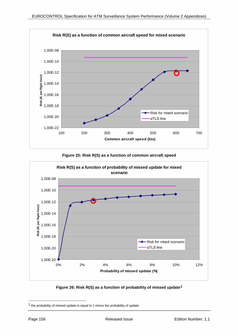
Figure 1: Aircraft position probability of update ..................................................................................... 12 Figure 2: 3 consecutive missed target reports in aircraft crossing scenario ......................................... 13 Figure 3: Impact of position accuracy on separation (aircraft crossing scenario) ................................. 14 Figure 4: Correlated error position in parallel route scenario ................................................................ 15 Figure 5: Impact of relative time difference ΔT on crossing scenario ................................................... 16 Figure 6: Impact of pressure altitude data age on vertical separation .................................................. 17 Figure 7: Impact of incorrect pressure altitude issue on vertical separation ......................................... 17 Figure 8: Impact of pressure altitude accuracy on vertical separation .................................................. 18 Figure 9: Impact of velocity vector errors on separation prediction – parallel route scenario ............... 20 Figure 10: Impact of velocitity vector amplitude error on separation prediction – in-trail scenario ....... 20 Figure 11: Falsely confirmed track close to true track ........................................................................... 21 Figure 12: Maximum horizontal position ................................................................................................ 37 Figure 13: Maximum horizontal position ................................................................................................ 81 Figure 14: Hierarchy of Air Traffic Services ......................................................................................... 112 Figure 15: Crossing track scenario 5 NM separation .......................................................................... 143 Figure 16: Crossing track scenario 3 NM separation .......................................................................... 144 Figure 17: Same track scenario 5 NM separation ............................................................................... 145 Figure 18: Same track scenario 3 NM separation ............................................................................... 146 Figure 19: Reciprocal track scenario 5 NM separation ....................................................................... 147 Figure 20: Reciprocal track scenario 3 NM separation ....................................................................... 148 Figure 21: Vertical crossing track scenario 5 NM separation at 1500 ft/mn ........................................ 149 Figure 22: Vertical crossing track scenario 5 NM separation at 3000 ft/mn ........................................ 150 Figure 23: Vertical crossing track scenario 3 NM separation at 1500 ft/mn ........................................ 151 Figure 24: Vertical crossing track scenario 3 NM separation at 3000 ft/mn ........................................ 152 Figure 25: Risk R(S) as a function of common aircraft speed ............................................................. 156 Figure 26: Risk R(S) as a function of probability of missed update .................................................... 156 Figure 27: Risk R(S) as a function of update interval .......................................................................... 157 Figure 28: Risk R(S) as a function of horizontal separation minimum ................................................ 157 Figure 29: Risk R(S) as a function of Pm ............................................................................................. 158 Figure 30: Risk R(S) as a function of common aircraft speed ............................................................. 159 Figure 31: Risk R(S) as a function of probability of missed update .................................................... 159 Figure 32: Risk R(S) as a function of update interval .......................................................................... 160 Figure 33: Risk R(S) as a function of horizontal separation minimum ................................................ 160 Figure 34: Risk R(S) as a function of Pm ............................................................................................. 161
EUROCONTROL Specification for ATM Surveillance System Performance (Volume 2 Appendices)
Edition Number: 1.1 Released Issue Page 9
EXECUTIVE SUMMARY
This document provides performance requirements for ATM surveillance system when supporting 3 and 5 NM horizontal separation applications. This specification has been developed by an international group of experts from air navigation service providers, system manufacturers and national supervisory authorities.
This specification was developed in parallel with the draft Surveillance Performance and Interoperability Implementing Rule (SPI IR). On 21 November 2011 the final rule (Commission Implementing Regulation (EU) No 1207/2011) was published within European Union Official Journal. This specification therefore complements and refines the requirements included in this Single European Sky (SES) regulation.
This document can be used by air navigation service providers to define, as required by Commission Implementing Regulation (EU) No 1207/2011 of 22 November 2011, the minimum performance that their surveillance system must meet. This specification also defines how the associated conformity assessment must be performed.
This specification is generic and independent of technology. It must be supplemented by specific local requirements that may be due to safety constraints, to local technological choices, to the needs to support other services and functions and other local requirements. This specification is written to be compatible with recently published industry standards (EUROCAE) applicable to specific surveillance sensor technologies (ADS-B RAD and NRA and WAM).
The requirements defined in this specification are mainly derived from practical experience, operational needs analysis studies and technical studies.
Particular attention was paid to ensuring that each performance requirement was achievable and measurable and accompanied by an associated conformity assessment process. In this regard, measurements made on the basis of opportunity traffic are preferable as they fully reflect the system performance in its operational environment. Alternatively flight trials may also be undertaken. Proof offered through system design files or by system design assurance, the use of a test transponder or an injected test target is also acceptable when the other options are impracticable.
For the time being this specification is addressing the ATM surveillance system performance needed to support 3 and 5 NM horizontal separation. In the future this specification may be extended to address other air traffic services (e.g. other horizontal separation minima) and/or functions.
This volume 2 contains informative appendices whereas volume 1 contains the mandatory and recommended requirements.
The changes introduced to raise this specification to Edition 1.1 correct minor errors and address clarification requests which have become apparent since the publication of Edition 1.0.
It should be noted that further work to develop a Generic Surveillance Safety and Performance Requirement (GEN SUR SPR) document is being performed in the frame of EUROCAE Working Group 102. Upon its formal publication the GEN SUR SPR document will complement and in some aspects is expected to partially supersede this EUROCONTROL Specification. It is therefore foreseen that a further update to this specification may be required in the future to reflect and incorporate elements of the published GEN SUR SPR.
It may be of interest to the reader to note that whilst European Commission Implementing Regulation (EU) No 1207/2011 of 22 November 2011 referred to in this document was amended by Commission Implementing Regulation (EU) No 1028/2014 of 26 September 2014 the amendment does not affect the surveillance system performance requirements.
EUROCONTROL Specification for ATM Surveillance System Performance (Volume 2 Appendices)
Edition Number: 1.1 Released Issue Page 11
APPENDIX - I JUSTIFICATIONS OF THE SPECIFIED PERFORMANCE METRICS
I - 1 Approaches for defining performance requirement criteria As the horizontal separation service is provided to two individual aircraft (see OPA scenarios in Appendix - V), the performance requirements for cooperative surveillance have been defined, as far as possible, per flight/aircraft.
Additionally, such an approach is considered necessary as the performance of cooperative surveillance systems is increasingly reliant upon the performance of the aircraft domain components.
The following paragraphs provide a rational for the requirements which have not been explicitely defined per flight.
R3 (long 3D gaps) and R5 (horizontal position correlated errors) are addressing events linked to flights. For these two requirements, the elementary performance is assessed per flight and then aggregated for all flights.
R6 (time consistency) is applicable to couples of aircraft in close proximity, the elementary performance indicator is per couple of flights, and then aggregated for all relevant couples of flights.
R7, R8, R10, R14, R15, R16, R17 and R18 are currently specified globally because of a lack of experience in assessing those indicators per flight. Nevertheless it is expected that in the future these performance requirement criteria will be defined per flight. For R14 there is already a recommended requirement specified per flight.
R12 and R13 are implicitely per flight as they refer to events on individual flights.
R19 is not applicable to flights as it is related to false uncorrelated target reports.
R20 is indirectly related to individual flights: falsely confirmed tracks close to true tracks (flights).
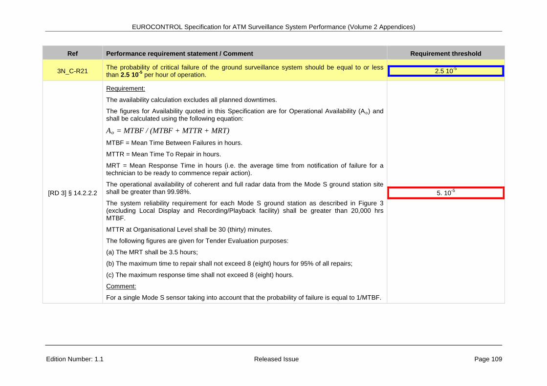
R21 is a system global performance and is therefore not applicable to individual flights.
I - 2 An example of top-down approach to define performance requirement criteria Appendix - VI provides an example of a top-down approach, on the basis of a modelisation of the horizontal position error, for justifying the choice of the following performance metrics:
• Measurement interval. • Horizontal position RMS error. • Probability of update of horizontal position.
It is also based on other performance characteristics that are not specified in this document (e.g. probability to have a second missed target report after a first one and the shape of the tail distribution of the horizontal position error) and on a number of parameters that are specified in Appendix - VI and further described in the documents [RD 22] and [RD18].
I - 3 Measurement interval The provision of aircraft separation service is relying on the regular provision, at a given measurement interval, of surveillance information on the aircraft being separated. The measurement interval is not a performance requirement but is a technical parameter from which other performance indicators are derived (probability of update of data items). In principle, in case of a surveillance system with a periodic output, the measurement interval should be a multiple of the system nominal update interval/periodicity
EUROCONTROL Specification for ATM Surveillance System Performance (Volume 2 Appendices)
Page 12 Released Issue Edition: 1.1
The required values are copied from the EUROCONTROL Standard Document for Radar Surveillance in En-route Airspace and Major Terminal Areas (see document [RD 2]). They have also been retained for providing 3 and 5 NM separation in the context of the ADS-B RAD application (see document [RD 15]) and they have also been specified for WAM system (see document [RD 16]).
I - 4 Probability of update of horizontal position The provision of aircraft separation service is relying on the regular provision, at each measurement interval, of the horizontal position of the aircraft being horizontally separated. Therefore, for cooperative systems, a requirement has been defined for the probability of update of horizontal position of each flight. In addition and as recommendation, this requirement is supplemented with a requirement on the global (i.e. aggregation of all flights) probability of update of aircraft horizontal position with a higher threshold.
For non-cooperative systems, for the time being, the mandatory requirement for the probability of update is defined globally. It is however recommended to apply a requirement per flight as for cooperative systems.
The following diagram (Figure 1) clearly shows that updated aircraft horizontal positions are needed to maintain aircraft horizontal separation in the case of the aircraft crossing scenario.
Figure 1: Aircraft position probability of update
The required value for the probability of update of horizontal position per flight for cooperative system is derived from the figure specified for horizontal position and pressure data items in [RD 15].
Separation
Separation
Sepa
ratio
n
Separation
Separation
Separation
Sepa
ratio
n
Separation
EUROCONTROL Specification for ATM Surveillance System Performance (Volume 2 Appendices)
Edition Number: 1.1 Released Issue Page 13
The required value for the global probability of update of horizontal position for non-cooperative system is derived from the figure specified for PSR horizontal position in [RD 2].
I - 5 Ratio of missed reports involved in long gaps Whilst some missed positions (in the horizontal dimension and/or in the vertical dimension) can be tolerated, it is considered that the missed positions must not be consecutive. Therefore a requirement has been defined on the ratio of missed target report involved in long gaps.
The diagram below (Figure 2) shows the impact of 3 consecutive missed target reports in the case of the aircraft crossing scenario.
The required values have been discussed and agreed by the SSTF members on the basis of their current experience. A more stringent value may be defined when more experience will be available.
It is to be noted that this indicator, as it is currently defined, does not address long track initiation delay or early track termination. However the probability of update is impacted by such events.
Missing 2nd update Missing 3rd update
Separation
Separation?
Separation?
Sepa
ratio
n
Missing 1st update
Separation?Areas of uncertainty
due to missedposition reports
Missing 2nd update Missing 3rd update
Separation
Separation?
Separation?
Sepa
ratio
n
Missing 1st update
Separation?Areas of uncertainty
due to missedposition reports
EUROCONTROL Specification for ATM Surveillance System Performance (Volume 2 Appendices)
Page 14 Released Issue Edition: 1.1
I - 6 RMS error of horizontal position The provision of aircraft separation service is relying on the provision, at each measurement interval, of accurate positions of the aircraft being separated. Therefore a requirement has been defined for the position accuracy of aircraft at the time it is output. A threshold has been defined for global assessment (all target reports) and another threshold has been defined per flight (all target reports corresponding to the same flight. The threshold per flight is slightly greater (i.e. 10%) to take account for the limited number of samples that may increase the RMS assessment per flight compared to the global RMS assessment.
The following diagram (Figure 3) shows the impact of horizontal position accuracy on the horizontal separation service. The uncertainty of the horizontal position is represented by an ellipse around the displayed position.
Figure 3: Impact of position accuracy on separation (aircraft crossing scenario)
The required global values are copied from the EUROCONTROL Standard Document for Radar Surveillance in En-route Airspace and Major Terminal Areas (see document [RD 2]).
Actual horizontal separation?
Areas of uncertainty around displayed
aircraft positions due to position accuracy
Actual horizontal separation?
Actual horizontal separation?
Areas of uncertainty around displayed
aircraft positions due to position accuracy
Actual horizontal separation?
EUROCONTROL Specification for ATM Surveillance System Performance (Volume 2 Appendices)
Edition Number: 1.1 Released Issue Page 15
I - 7 Ratio of target reports involved in sets of consecutive correlated horizontal position errors The provision of aircraft separation service is relying on the extrapolation of the future situation by the air traffic controller. A set of consecutive correlated errors in the same direction may invalidate the predictions made by the controller. This can be illustrated on Figure 4 on the basis of the parallel route scenario. On this figure the displayed aircraft position are shown in bright color whereas the real aircraft positions of the blue aircraft are shown in shaded color.
Figure 4: Correlated error position in parallel route scenario
In this case, after 3 correlated errors the controller will be convinced that the blue aircraft has kept its initial route whereas, in the reality, it is becoming closer to the red aircraft.
The required values have been derived from the figures specified for 3 and 5 NM separation applications in document [RD 24] for mono radar systems.
I - 8 Relative time of applicability of close horizontal positions There is already a requirement on the accuracy of the aircraft position at the time it is output nevertheless there is an additional uncertainty which is due to the fact that all aircraft positions are not applicable (e.g. calculated) at the same time. The contribution to the relative position error of this time difference between two aircraft being separated must therefore be limited.
App
aren
t and
act
ual
sepa
ratio
n
Act
ual s
epar
atio
n
App
aren
t sep
arat
ion
App
aren
t sep
arat
ion
Act
ual s
epar
atio
n
Blue aircraft displayed trajectory
Blue aircraft actual trajectoryApp
aren
t and
act
ual
sepa
ratio
n
Act
ual s
epar
atio
n
App
aren
t sep
arat
ion
App
aren
t sep
arat
ion
Act
ual s
epar
atio
n
Blue aircraft displayed trajectory
Blue aircraft actual trajectory
EUROCONTROL Specification for ATM Surveillance System Performance (Volume 2 Appendices)
Page 16 Released Issue Edition: 1.1
This is illustrated on the basis of the crossing scenario on Figure 5 below where the blue aircraft position is calculated at T1 and the red aircraft position is calculated a little bit later at T1 + ΔT.
Figure 5: Impact of relative time difference ΔT on crossing scenario
The required values have been copied from the figures specified for 3 NM separation applications in document [RD 24]. The SSTF agreed to apply the same figure for 3 and 5 NM separation.
I - 9 Data age and ratio of incorrect pressure altitude
I - 9.1 Data age of pressure altitude When the pressure altitude data item provided to the controller is the last pressure altitude that has been reported by the aircraft (either in response to an interrogation or through a spontaneous squitter message) it is important for the controller that this data item is provided as quickly as possible to reflect the reality. Therefore a requirement has been defined on the average and maximum data age of the pressure altitude.
The required values have been discussed and agreed by the SSTF members on the basis of their experience.
Apparent separation
Blue aircraft displayed horizontal position (calculated at T1)
Blue aircraft real horizontal position at
T1 + ΔT
Red aircraft displayed horizontal position
(calculated at T1 + ΔT)
Actual
sepa
ration
Apparent separation
Blue aircraft displayed horizontal position (calculated at T1)
Blue aircraft real horizontal position at
T1 + ΔT
Red aircraft displayed horizontal position
(calculated at T1 + ΔT)
Actual
sepa
ration
EUROCONTROL Specification for ATM Surveillance System Performance (Volume 2 Appendices)
Edition Number: 1.1 Released Issue Page 17
The diagram below (Figure 6) illustrates the impact of pressure data age on vertical separation.
Figure 6: Impact of pressure altitude data age on vertical separation
I - 9.2 Ratio of incorrect pressure altitude In addition to what is stated in previous sub-section I - 9, it is also important to make sure that during the processing of the pressure altitude its value is not corrupted. Therefore a requirement has been defined on the maximum ratio of cases when this data item is incorrect/corrupted.
The required value has been derived from the figure specified for a single SSR in document [RD 2]. Single SSR is still used in Europe to provide 3 and 5 NM separation, either in pure stand-alone mode or integrated in a mosaic system.
The diagram below (Figure 7) illustrates the impact that one case of incorrect pressure altitude may have on vertical separation.
Figure 7: Impact of incorrect pressure altitude issue on vertical separation
App
aren
t and
act
ual
sepa
ratio
n
Pressure altitude data age
Act
ual s
epar
atio
n
App
aren
t sep
arat
ion
Pressure altitude data age
App
aren
t and
act
ual
sepa
ratio
n
Pressure altitude data age
Act
ual s
epar
atio
n
App
aren
t sep
arat
ion
Pressure altitude data age
App
aren
t and
act
ual
sepa
ratio
n
App
aren
t sep
arat
ion
Act
ual s
epar
atio
n
Pressure altitude errorA
ppar
ent a
nd a
ctua
l se
para
tion
App
aren
t sep
arat
ion
Act
ual s
epar
atio
n
Pressure altitude error
EUROCONTROL Specification for ATM Surveillance System Performance (Volume 2 Appendices)
Page 18 Released Issue Edition: 1.1
I - 10 Unsigned error of pressure altitude Alternatively to the approach described in section I - 9, the correctness of pressure altitude data item may be assessed on the basis of its accuracy (i.e. similarly as the horizontal position data item).
It is to be noted that this requirement may be applied even though the pressure altitude data item is just forwarded.
The required values have been discussed and agreed by the SSTF members on the basis of actual measurements made by an ANSP on its operational systems.
The diagram below (Figure 8) illustrates the impact that pressure altitude accuracy may have on vertical separation.
Figure 8: Impact of pressure altitude accuracy on vertical separation
I - 11 Delay of transmission of SPI and emergency indicators Because it is important for the controller to timely identify SPI and emergency indicators a performance has been defined for the delay to transmit this information from when it is available for the first time at sensor level up to when it is provided/output by the system.
The required value have been discussed and agreed by the SSTF members on the basis of their experience.
I - 12 Delay of transmission of change of aircraft identity Because it is important for the controller to timely identify that the operational identity (Mode A code or “aircraft identification (ACID)”) of an aircraft has changed a performance has been defined for the delay to transmit this from when it is available for the second time at sensor level up to when it is provided/output by the system.
The required values have been discussed and agreed by the SSTF members on the basis of their experience.
I - 13 Probability of update of correct aircraft identity The provision of aircraft separation service is relying on the identification of the aircraft being separated. Therefore a requirement has been defined for the probability of update of aircraft identity of each aircraft.
Act
ual v
ertic
al s
epar
atio
n?
Act
ual v
ertic
al
sepa
ratio
n?
Pressure altitude accuracy
Pressure altitude accuracy
Act
ual v
ertic
al s
epar
atio
n?
Act
ual v
ertic
al
sepa
ratio
n?
Pressure altitude accuracy
Pressure altitude accuracy
EUROCONTROL Specification for ATM Surveillance System Performance (Volume 2 Appendices)
Edition Number: 1.1 Released Issue Page 19
It is to be noted that this requirement on the probability of update of the aircraft identity data item is a requirement on the provision of the information at the output of the system and does not require the extraction from the aircraft at each measurement interval. Such extraction should only be performed when needed (i.e. when the aircraft notifies a change) and/or periodically but on the basis of a longer period in order to limit, as far as possible, the occupancy of the 1090 MHz band.
The required value is copied from European Mode S station functional specification (see document [RD 3]). Mode S stations are used in Europe to provide 3 and 5 NM separation.
I - 14 Ratio of incorrect aircraft identity It is important to timely provide the aircraft identity to the controller when it has changed and it is also important to make sure that during the processing of the aircraft identity its value has not been corrupted. Therefore a requirement has been defined on the ratio of cases when this data item is incorrect/corrupted.
The required values have been derived from the figure specified for a single SSR in document [RD 2]. Single SSR is still used in Europe to provide 3 and 5 NM separation, either in pure stand-alone mode or integrated in a mosaic system.
I - 15 RMS errors of rate of climb/descent The provision of aircraft rate of climb/descent is recommended to support the provision of separation service. When providing separation between aircraft the intentions of both aircraft are important for the controller to be able to predict that no conflict will happen in the near future. In that case it is important to make sure that the quality of this information is good enough for the controller to perform separation.
The required values have been discussed and agreed by the SSTF members on the basis of actual measurements made by an ANSP on its operational systems.
It is to be noted that this information may be reduced to a trend, i.e. stable, climbing or descending. In that case an alternate performance criterion will have to be defined.
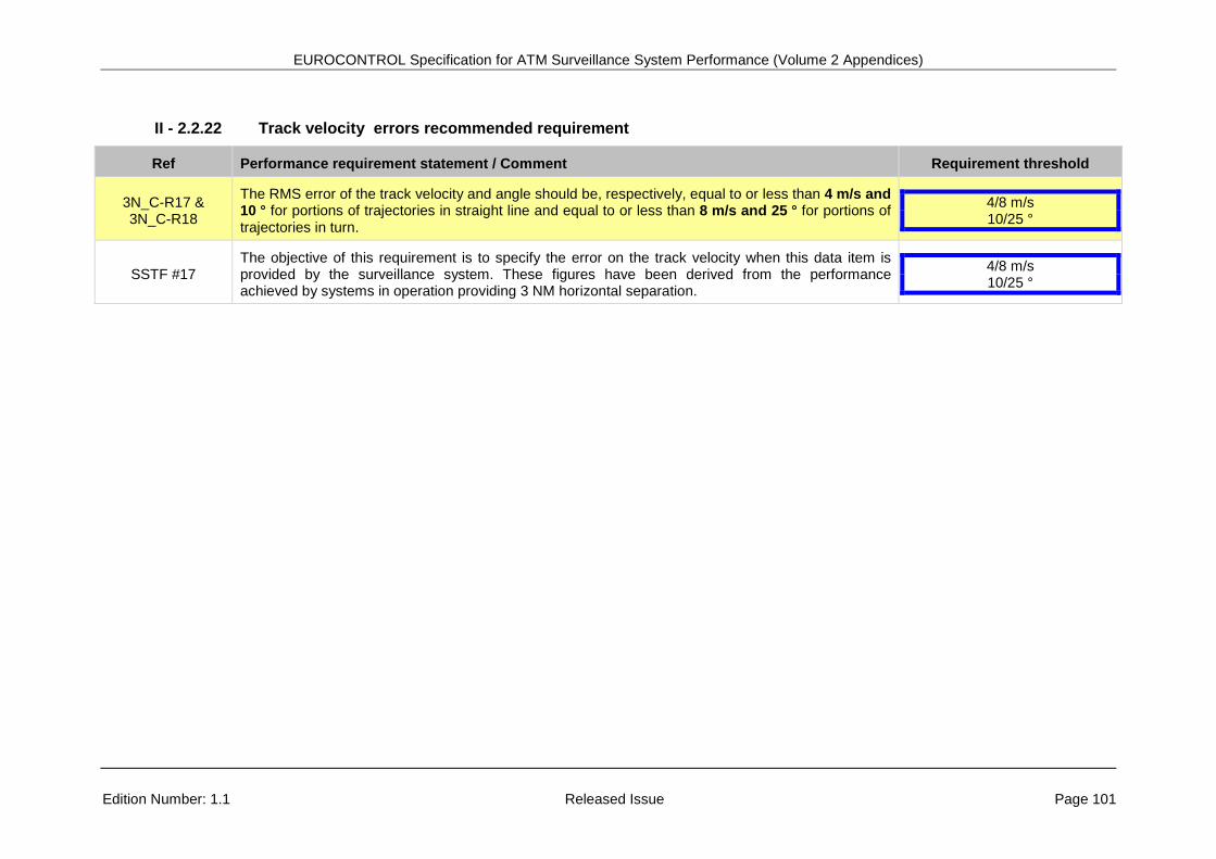
I - 16 RMS errors of track velocity vector components The provision of aircraft velocity vector is recommended to support the provision of separation service. When providing separation between aircraft the intentions of both aircraft are important for the controller to be able to predict that no conflict will happen in the near future. This information can be provided indirectly to the controller under the form of the past aircraft horizontal positions but it is more and more often provided under the form of a velocity vector. In that case it is important to make sure that the quality of this information is good enough for the controller to perform separation.
The required values have been discussed and agreed by the SSTF members on the basis of actual measurements made by an ANSP on its operational systems.
EUROCONTROL Specification for ATM Surveillance System Performance (Volume 2 Appendices)
Page 20 Released Issue Edition: 1.1
The following diagrams (Figure 9 and Figure 10) illustrate the impact that velocity vector (angle and/or amplitude) error may have on the prediction of future separation between aircraft in the case of the parallel route scenario and of the in-trail scenario.
Figure 9: Impact of velocity vector errors on separation prediction – parallel route scenario
Figure 10: Impact of velocitity vector amplitude error on separation prediction – in-trail
scenario
I - 17 Density of uncorrelated false target reports The provision of aircraft separation by controller requires a careful monitoring of the air situation picture, controller attention must not be disturbed by spurious events as false target reports, i.e. aircraft position reports that are displayed but which do not correspond to actual aircraft positions. In the EUROCONTROL Standard Document for Radar Surveillance in En-route Airspace and Major Terminal Areas the maximum allowable number of false target reports is specified as a maximum ratio over the total number of target reports. This approach was found not appropriate, from an operational point of view, as it allows more false target reports when there are more true target reports, i.e. when the air situation picture is complex.
Sep
arat
ion
Sep
arat
ion
Areas of uncertainty due
to velocity vector error
Velocity vectors
Possible separation
at next updateS
epar
atio
n
Sep
arat
ion
Areas of uncertainty due
to velocity vector error
Velocity vectors
Possible separation
at next update
Uncertainty of predicted horizontal position due to velocity amplitude error
Predicted separation worst case
Uncertainty of predicted horizontal position due to velocity amplitude error
Uncertainty of predicted horizontal position due to velocity amplitude error
Predicted separation worst case
Uncertainty of predicted horizontal position due to velocity amplitude error
EUROCONTROL Specification for ATM Surveillance System Performance (Volume 2 Appendices)
Edition Number: 1.1 Released Issue Page 21
In order to address this issue, EUROCONTROL sub-contracted a study (see [RD 21]) in 2007-2008 to derive the operational requirements into technical requirements applicable to the output of the surveillance system. One of the requirements proposed by this study is to limit, within an operational sector, the density (per hour) of uncorrelated false target reports being output. In order to further refine the requirement it was agreed that the usual size of a sector is 900 NM² (30 NM x 30 NM) and 100 NM² (10 NM x 10 NM) for respectively 5 and 3 NM separation.
The required values have been proposed in document [RD 21]. They were derived from brainstorming with operational staff and were then confirmed on the basis of basic operational scenarios.
I - 18 Number of falsely confirmed tracks close to true tracks The provision of aircraft separation by controller requires a careful monitoring of the air situation picture, the presence of an unexpected track in the vicinity of aircraft under control will generate an additional workload to the controller in order to determine whether the displayed track correspond to a true aircraft or not. In the EUROCONTROL Standard Document for Radar Surveillance in En-route Airspace and Major Terminal Areas the maximum allowable number of false target reports is specified as a maximum ratio over the total number of target reports. This approach was found not appropriate, from an operational point of view, as it does not make any difference between correlated false target reports that are critical and uncorrelated false target reports that are more a nuisance.
In order to address this issue, EUROCONTROL sub-contracted a study (see [RD 21]) in 2007-2008 to derive the operational requirements into technical requirements applicable to the output of the surveillance system. The other requirement proposed by this study to address this aspect is to limit the number of falsely confirmed track that are located close to true tracks. This is further illustrated on Figure 11 below on the basis of the crossing route scenario.
Figure 11: Falsely confirmed track close to true track
Separation
Separation
True track
Truetrack
Potentialconflicts Falsely
confirmedtrack
Potentialconflicts
Separation
Separation
True track
Truetrack
Potentialconflicts Falsely
confirmedtrack
Potentialconflicts
EUROCONTROL Specification for ATM Surveillance System Performance (Volume 2 Appendices)
Page 22 Released Issue Edition: 1.1
The required values have been proposed in document [RD 21]. They were derived from brainstorming with operational staff and were then confirmed on the basis of basic operational scenarios.
EUROCONTROL Specification for ATM Surveillance System Performance (Volume 2 Appendices)
Edition Number: 1.1 Released Issue Page 23
APPENDIX - II TRACEABILITY AND JUSTIFICATION MATRIX
II - 1 Conventions Shading:
Light green shading means mandatory ESASSP requirements
Light yellow shading means recommended ESASSP requirements
Framing:
Blue framing means referenced requirement is identical to ESSASP requirement
Sky blue framing means referenced requirement is very close to ESASSP requirement (+/- 10%)
Green framing means referenced requirement is more demanding than ESASSP requirement
Red framing means referenced requirement is less demanding than ESASSP requirement
Pink framing means referenced requirement is different than ESASSP requirement
EUROCONTROL Specification for ATM Surveillance System Performance (Volume 2 Appendices)
Edition Number: 1.1 Released Issue Page 24
II - 2 Traceability, justification and links to equivalent requirement statement
II - 2.1 5N_C: 5 NM horizontal separation
II - 2.1.1 Measurement interval mandatory requirements
5N_C-R1 The applicable measurement interval for horizontal position, pressure altitude and aircraft identity data items shall be set to 8 s or less. 8 s
[RD 2] § 5.2.4 Requirement:
Surveillance information updates shall enable the display updates to be less than or equal to 8 seconds in en-route airspace.
8 s
[RD 14] SPR 19 § 3.5.2
Requirement:
For 5 NM separation – The update interval for Surveillance Reports containing any new ADS-B position data associated with any single aircraft shall be no longer than 10s with a probability of 95%.
Comment:
For ADS-B only.
10 s
[RD 24] Exigence 18
Requirement:
The duration separating two screen refreshes relating to the same aircraft shall not in principle exceed the following:
• 8 s for a target separation minimum M, if 3 NM < M ≤ 5 NM
8 s
EUROCONTROL Specification for ATM Surveillance System Performance (Volume 2 Appendices)
5N_C-R1 The applicable measurement interval for horizontal position, pressure altitude and aircraft identity data items shall be set to 8 s or less. 8 s
[RD 20] § 6.3.3
Proposed requirement:
The maximum data age of pressure altitude measured at the output of the ground system is: • 1000ft separation = 5s • 2000ft separation = 8s
Note:
The different figures depending on the applied VSM were due to the the assumption of the same nominal aircraft vertical speed for 3 NM/1000 ft separation and 5 NM/1000 ft separation. The SSTF agreed that a lower nominal vertical speed should be assumed for 5 NM/1000 separation as the vertical capabilities of aircraft in the en-route airspace are lower.
5 s 8 s
[RD 15] SPR 49
Requirement:
For 5 NM separation – The probability of providing a Surveillance Report containing newly received ADS-B Position data of sufficient quality associated with any aircraft in En Route airspace within 8 seconds shall be 97%.
Comment:
For ADS-B only.
8 s
[RD 16] § 3.3.1
Requirement:
The defined Update interval shall not exceed the following: • 8 seconds for the En-route application
Comment:
For WAM only.
8 s
EUROCONTROL Specification for ATM Surveillance System Performance (Volume 2 Appendices)
Edition Number: 1.1 Released Issue Page 26
II - 2.1.2 Measurement interval recommended requirements
5N_C-R1 The applicable measurement interval for horizontal position, pressure altitude and aircraft identity data items should be set to 6 s or less. 6 s
SSTF #12 It was agreed during SSTF meeting #12 that to take into account the future traffic increase in Europe it is needed to align the measurement interval for future system to the measurement interval currently applied in high-medium density airspace.
6 s
EUROCONTROL Specification for ATM Surveillance System Performance (Volume 2 Appendices)
Edition Number: 1.1 Released Issue Page 27
II - 2.1.3 Horizontal position probability of update mandatory requirement
5N_C-R2 The probability of update of the horizontal position in accordance with the applicable measurement interval shall be equal to or higher than 97 % per flight. 97 % (per flight)
[RD 2] § 6.3.2.1
Requirement:
Target Position Detection
Overall probability of detection: > 97 %
Comment:
For 1 SSR only.
For 2 independent SSR’s the requirement should be 99.91 %.
Not possible to derive a requirement per flight.
97 % or 99.91 % (global)
[RD 14] SPR 19 § 3.5.2
Requirement:
For 5 NM separation – The update interval for Surveillance Reports containing any new ADS-B Position data associated with any single aircraft shall be no longer than 10s with a probability of 95%.
95 % (per flight)
EUROCONTROL Specification for ATM Surveillance System Performance (Volume 2 Appendices)
5N_C-R2 The probability of update of the horizontal position in accordance with the applicable measurement interval shall be equal to or higher than 97 % per flight. 97 % (per flight)
[RD 24] Exigence 18
Requirement:
The duration separating two screen refreshes relating to the same aircraft shall not in principle exceed the following:
• 8 s for a target separation minimum M, if 3 NM < M ≤ 5 NM
Any exceeding of these limits shall be considered individual cases and shall accordingly be the subject of a detailed analysis included in the Radar Separation Minimum Dossier (RSMD).
Such analysis will make it possible to ascertain the cause of the occurrence, the potential operational implications, its classification in the seriousness table, a theoretical estimation of its frequency, the possible proposal of mitigating measures and its acceptability vis-à-vis regulations.
Comment:
According to the above, any missed target report should be very rare as it will require a specific analysis. Although it is not expressed as a probability of update per flight, it is deemed that this requirement is more demanding.
?
[RD 15] SPR 49
Requirement:
For 5 NM separation – The probability of providing a Surveillance Report containing newly received ADS-B Position data of sufficient quality associated with any aircraft in En Route airspace within 8 seconds shall be 97%.
Comment:
For ADS-B only. It is assumed that “ADS-B Position data” encompasses all the data items listed in SPR 27which include aircraft horizontal position data and pressure altitude.
97 % (per flight)
[RD 16] § 3.3.3 & 3.3.6
Requirement:
The Probability of position detection within the defined Update interval shall be greater than or equal to 97% for any target.
97% (per flight)
EUROCONTROL Specification for ATM Surveillance System Performance (Volume 2 Appendices)
Edition Number: 1.1 Released Issue Page 29
II - 2.1.4 Horizontal position probability of update recommended requirement
5N_C-R2 The probability of update of the horizontal position in accordance with the applicable measurement interval (see Req. 01) should be equal to or higher than 99 % globally and equal to or higher than 97 % per flight.
99 % (global) 97 % (per flight)
SSTF #12
It was agreed during SSTF meeting #12 that to take into account the future traffic increase in Europe it is needed to align the probability of update of positional information for future system to the probability of update of positional information currently achieved in high-medium density airspace.
99 % (global)
SSTF #21 It is proposed to supplement mandatory requirement of 97 % per flight with 99% global. 99 % (global) 97 % (per aircraft)
EUROCONTROL Specification for ATM Surveillance System Performance (Volume 2 Appendices)
Edition Number: 1.1 Released Issue Page 30
II - 2.1.5 Ratio of missed 3D position involved in long gaps mandatory requirement
5N_C-R3 The ratio of missed 3D position (either horizontal position or pressure altitude missing) involved in long gaps (longer than 3 x 8 s + 10% = 26.4 s) shall be equal to or less than 0.5 %. 0.5 %
SSTF #12-15-22
The objective of this requirement is to limit the size of trajectory gaps without full 3D position information. The inclusion of the requirement was agreed at SSTF meeting #12 and the length of long gap was agreed during STTF meeting #15. At meeting #22 it was agreed to specify an initial value of 0.5 % until more feedback is collected ( see Appendix I - 5).
0.5 %
[RD 16] § 3.3.4
Requirement:
The probability of long position gap for more than 3 times the maximum Update interval +10% (26.4 seconds for En-route application and 16.5 seconds for TMA application) shall be less than or equal to 0.1%.
0.1%
EUROCONTROL Specification for ATM Surveillance System Performance (Volume 2 Appendices)
Edition Number: 1.1 Released Issue Page 31
II - 2.1.6 Horizontal position error mandatory requirement
5N_C-R4 Horizontal position error, including measurement error and error due to information latency, shall be equal to or less than 500 m RMS globally and shall be equal to or less than 550 m RMS per flight.
500 m (global)
550 m (per flight)
[RD 2] § 5.2.3
Requirement:
The positional accuracy of the surveillance radar data available, at the control position, shall have an error distribution with a root mean square (RMS) value equal to or less than 500 metres (m) for en-route airspace.
500 m (global)
[RD 14] SPR 1 § 3.4.2.1
Requirement: For ADS-B Airborne, the 95% accuracy of the horizontal position shall be less than 0.5 NM (i.e. NACP ≥ 5).
Quality indicators that are transmitted in ADS-B messages shall account for any uncompensated latency on-board the aircraft. NOTE1: Quality Indicators, particularly accuracy, as used in this document include all contributing
factors for the uncertainty of position data with respect to the time of applicability for that data. These factors include the uncertainty of the position measurement and any uncompensated latency prior to transmission of the data.
Comments:
Equivalent requirements for ADS-B only (926 m converted in RMS, assuming Rayleigh distribution, gives 535 m), but does not take into account position error due to latency of the information on the ground. There are separated requirements for specifying information latency (Airborne part: less than 1.5 second for 95%, ground part: less than 0.5 second for 95%).
In [RD 14] Appendix B.1.3 it is further stated: “Finally, any uncompensated on-board latency or timing uncertainties that are not known to the ground will have the effect of degrading the position accuracy (predominantly in the along-track direction) of the ADS-B information received by the ground.”
Therefore it is unclear whether or not the error due to uncompensated latency is included or not in requirement SPR 1.
535 m (global)
535 m (per flight)
EUROCONTROL Specification for ATM Surveillance System Performance (Volume 2 Appendices)
5N_C-R4 Horizontal position error, including measurement error and error due to information latency, shall be equal to or less than 500 m RMS globally and shall be equal to or less than 550 m RMS per flight.
500 m (global)
550 m (per flight)
[RD 24] Exigence 12
Requirement:
The overall RMS shall not exceed the following thresholds: • 500 m for a target separation minimum of 5 NM
Comment:
It should be noted that the requirement shall also be met when the measurement is made on the basis of turning aircraft trajectories only.
500 m (global)
[RD 17] § 6.4 Tables 15 & 16
Proposed requirement:
Position error standard deviation shall be less than 1852 m.
Comment:
Even though it is not possible to convert this value to RMS it is deemed less demanding.
? m
[RD 18] § 10.13 Table 3 & § 10.15
Table 4
Proposed requirement:
Proposed values for 95% containment value is 556 m (0.3 NM) with a standard deviation of 185 m (0.1 NM).
Comment:
Even though it is not possible to convert these values to RMS it is deemed more demanding.
? m
EUROCONTROL Specification for ATM Surveillance System Performance (Volume 2 Appendices)
5N_C-R4 Horizontal position error, including measurement error and error due to information latency, shall be equal to or less than 500 m RMS globally and shall be equal to or less than 550 m RMS per flight.
500 m (global)
550 m (per flight)
[RD 3] § 4.2.6.2 & 4.2.6.3
Requirements:
(i) All SSR Random errors shall be less than 30 m RMS (1 sigma)
(ii) All Mode S Random errors shall be less than 15 m RMS (1 sigma)
All azimuth error standard deviations shall be less than 0.068° (one sigma)
Comment:
For a single Mode S sensor and without taking into account information latency (maximum 2 s).
Assuming no bias and that the azimuth error is Gaussian and is the main component of the position error and taking into account that maximum operational range for 5 NM separation is 200 NM (0.068° represents 440 m at 200 NM).
440 m (global)
EUROCONTROL Specification for ATM Surveillance System Performance (Volume 2 Appendices)
5N_C-R4 Horizontal position error, including measurement error and error due to information latency, shall be equal to or less than 500 m RMS globally and shall be equal to or less than 550 m RMS per flight.
500 m (global)
550 m (per flight)
[RD 15] SPR 8
Requirement:
For 5 NM separation – The 95% accuracy of the measured horizontal position shall be less than 308 metres (NACP = 7).
Comment:
More demanding requirement for ADS-B only (308 m @95% converted in RMS, assuming Rayleigh distribution, gives 178 m), but does not take into account position error due to information latency. There are separated requirements for specifying horizontal position latency (Airborne part: less than 0.6 second (uncompensated) for 95% SPR 24, ground part: less than 0.5 second for 95% SPR 35). It is also stated that these latencies are partially compensated (airborne) or fully compensated (ground), such compensation will introduce a budget error that is not possible to quantify without further assumptions.
178 m (per flight)
[RD 16] § 3.3.8 & 3.3.11
Requirement:
The Horizontal position errors shall not exceed: • 350 m RMS for the En-route application
NOTE1: The horizontal position error is calculated for the time of applicability provided by the target report.
In Periodic Predicted Mode, when the Predicted Position at time of output is transmitted, the maximum Processing delay shall be 0.5 second.
Comment:
Horizontal position error due to processing delay has to be added.
350 m
EUROCONTROL Specification for ATM Surveillance System Performance (Volume 2 Appendices)
Edition Number: 1.1 Released Issue Page 35
II - 2.1.7 Horizontal position error recommended requirement
5N_C-R4 Horizontal position error, including measurement error and error due to information latency, should be equal to or less than 350 m RMS global equal to or less than 385 m RMS er flight.
350 m (global)
385 m (per flight)
SSTF #12 It was agreed during SSTF meeting #12 that to take into account the future traffic increase in Europe it is needed to align the horizontal position core accuracy for future system to the horizontal position core accuracy currently achieved in high-medium density airspace.
350 m (global)
SSTF #21 At SSTF #21 it was agreed to supplement the global requirement on RMS horizontal position error with a requirement per flight with an additional margin to take account of the limited number of samples when performing an assessment per flight.
385 m (per flight)
EUROCONTROL Specification for ATM Surveillance System Performance (Volume 2 Appendices)
The criteria on horizontal position error for declaring a target report as outlier, including measurement error and error due to information latency, shall be equal to 2100 m. 2100 m
[RD 27] § 1.2.2.1.2.1
Requirement:
Maximum horizontal position error shall be less than half of the chosen separation minimum minus a specified safety buffer.
Note 1: The maximum horizontal position uncertainty is assumed to occur at the end of the update interval.
Comment:
The above value of 2100 m has been derived from the 4630 m value assuming a maximum aircraft speed (Vmax) of 600 knots (Volume 1 Annex C – 4.3.1), an update interval of 8 s and an aircraft size of 60 m. This is further illustrated on Figure 12 below.
4630 m
EUROCONTROL Specification for ATM Surveillance System Performance (Volume 2 Appendices)
The criteria on horizontal position error for declaring a target report as outlier, including measurement error and error due to information latency, shall be equal to 2100 m. 2100 m
Figure 12: Maximum horizontal position
Provided that the position error remains in the dark blue area the probability to be in collision during the period of display is null, even in the worst case of the two aircraft heading on. This simple approach does not address the evolution of the aircraft trajectory during the next updates.
Aircraft dimensions:60 m
Uncertainty area due to aircraft movement during
update period:Vmax x update interval
Uncertainty area due to horizontal position error:
Maximum horizontal position error
Horizontal separation
Aircraft dimensions:60 m
Uncertainty area due to aircraft movement during
update period:Vmax x update interval
Uncertainty area due to horizontal position error:
Maximum horizontal position error
Horizontal separation
EUROCONTROL Specification for ATM Surveillance System Performance (Volume 2 Appendices)
Edition Number: 1.1 Released Issue Page 38
II - 2.1.9 Ratio of correlated horizontal position errors recommended requirement
5N_C-R5 There should be no more than 0.03 % of position reports included in a series of correlated horizontal position errors in the same direction, larger than 926 m and during more than 3 applicable measurement intervals.
0.03 %
926 m
3 updates
[RD 24] Exigence 5
Requirement:
The ratio of plots with a correlated deviation (i.e. the plots with an across deviation greater than M/10 immediately preceded or followed (i.e. on the preceding or subsequent antenna revolutions) by two plots with an across deviation in the same direction greater than M/20) in the area of interest of the control unit served by the image evaluated shall not exceed 0.03%.
Comment:
M is the applicable separation minima (i.e. 5 NM)
Statement derived from SSR only requirements. The amount of error to declare correlated errors is smaller but is limited to across error.
0.03 %
926-463-463 m
463-463-926 m
3 updates
EUROCONTROL Specification for ATM Surveillance System Performance (Volume 2 Appendices)
Edition Number: 1.1 Released Issue Page 39
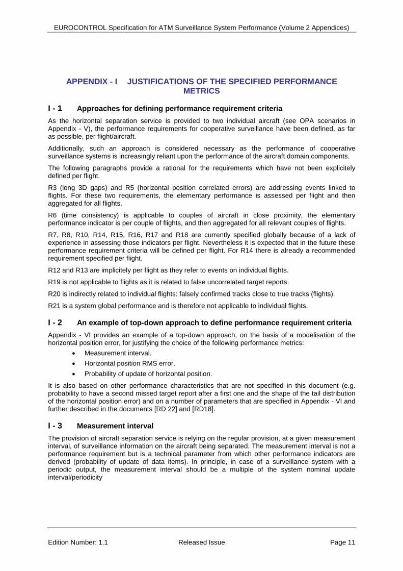
II - 2.1.10 Horizontal position relative time of applicability recommended requirement
5N_C-R6 The relative time of applicability of horizontal position of close aircraft (separated by less than 10 NM horizontally) should be equal to or less than 0.3 s RMS. 0.3 s
[RD 24] Exigence 16
Requirement:
The RMS of the time deviations separating the position update of the aircraft in proximity shall not exceed the following thresholds:
• 0.5 s for a target separation minimum M, if M = 5 NM
Comment:
The requirement is put on the relative time of display between aircraft separated by less than 10 NM.
In the frame of SSTF#12 it was agreed to keep the same requirement (0.3 s) for both applications.
0,5 s
EUROCONTROL Specification for ATM Surveillance System Performance (Volume 2 Appendices)
Edition Number: 1.1 Released Issue Page 40
II - 2.1.11 Correct pressure altitude probability of update mandatory requirement
5N_C-R7 The probability of update of correct pressure altitude in accordance with the applicable measurement interval shall be equal to or higher than 96 %. 96 %
[RD 2] § 6.3.2.4
Requirement:
Overall Mode C probability of code detection: > 96 %
Comment:
For 1 SSR only.
96 %
[RD 14] SPR 19 § 3.5.2
Requirement:
For 5 NM separation – The update interval for Surveillance Reports containing any new ADS-B Position data associated with any single aircraft shall be no longer than 10s with a probability of 95%.
Comment:
For ADS-B only, it is considered that ADS-B target reports always contain horizontal position and pressure altitude so the ratio should be 100 % minus the cases of pressure altitude integrity error.
100- %
[RD 15] SPR 49
Requirement:
For 5 NM separation – The probability of providing a Surveillance Report containing newly received ADS-B Position data of sufficient quality associated with any aircraft in En Route airspace within 8 seconds shall be 97%.
Comment:
For ADS-B only. It is assumed that “ADS-B Position data” encompasses all the data items listed in SPR 27which include aircraft horizontal position data and pressure altitude so the ratio should be 100 % minus the cases of pressure altitude integrity error.
100- %
[RD 16] § 3.3.3 & 3.3.6
Requirement:
The WAM system shall provide a correct and validated Mode C code within the defined Measurement interval with a probability greater than or equal to 96%.
96%
EUROCONTROL Specification for ATM Surveillance System Performance (Volume 2 Appendices)
Edition Number: 1.1 Released Issue Page 41
II - 2.1.12 Forwarded pressure altitude average data age mandatory requirements
5N_C-R8 The average data age of the forwarded pressure altitude reported in all target reports shall be equal to or less than 4 s. 4 s
SSTF #12
The objective of this requirement is to limit the latency of pressure altitude (forwarded data item) inside the surveillance system. There is currently no equivalent requirement in any standard from which this requirement can be traced. This value has been proposed during STTF meeting #12 and is based on current surveillance system experience.
4 s
[RD 2] § 6.7
Requirement:
The maximum target report delay shall be less than or equal to 2 seconds.
Comment:
Airborne latency is assumed to be negligible; therefore the global performance is better than the above specification.
2 + s
[RD 14] SPR 12 § 3.4.2.2 –
SPR 16 § 3.5.2
Requirement:
For barometric altitude, aircraft identification, mode A code, SPI and Emergency indicators, the Airborne Transmit Domain shall have a latency no greater than specified in current implementations for SSR.
The 95% latency for ADS-B Surveillance Reports (measured between points D and E2) shall be no greater than 0.5s.
Comment:
Airborne and transmission latencies are assumed to be negligible; therefore the global performance is better than the above specification.
0.5 + s
EUROCONTROL Specification for ATM Surveillance System Performance (Volume 2 Appendices)
5N_C-R8 The average data age of the forwarded pressure altitude reported in all target reports shall be equal to or less than 4 s. 4 s
[RD 15] SPR 35 § 3.4.2
Requirement: The 95% latency for ADS-B surveillance reports (measured between points D and E2 (output of the “Ground ADS-B Receive” function) shall be no greater than 0.5 seconds, excluding communication latency to the ATC processing system.
Comment:
Airborne latency is assumed to be the same as for SSR and is therefore negligible; therefore the global performance is better than the above specification.
0.5 + s
[RD 16] § 3.3.11
Requirement: In Periodic Delayed Mode, when the last received measured position within the Output Period is transmitted, the maximum Processing delay shall be less than or equal to the duration of the Output Period plus 1s.
Comment:
It is assumed that the WAM system under nominal condition will meet the requirement.
Max 9 s
EUROCONTROL Specification for ATM Surveillance System Performance (Volume 2 Appendices)
Edition Number: 1.1 Released Issue Page 43
II - 2.1.13 Forwarded pressure altitude maximum data age mandatory requirements
5N_C-R9 Any forwarded pressure altitude data item with an age greater than or equal to 16 s shall be considered as not available when assessing R3, R7, R8, R10 and R11
16 s
SSTF #21 Assuming that a large proportion (to be quantified) of the aircraft vertical movements are performed at a rate of climb/descent less than or equal to 3000 ft/mn, 16 s corresponds to the delay for a climbing descending aircraft to leave its initial flight level but to not have yet reached the next (above or below) flight level. In accordance with ICAO Document 4444 [RD 9] an aircraft is at a given flight level if its pressure altitude is within +/- 200 ft from that flight level (VSM = 1000 ft). 16 seconds is derived from 1000 ft minus 200 ft divided by the considered normal vertical speed 3000 ft/mn (or 50 ft/s).
16 s
At SSTF #21 it was agreed that this delays must be applicable for 100% of the cases, however it is also recognised that cases of higher data age may happen in rare cases. These cases should be analysed to avoid/minimise their re-occurence.
At SSTF #22 it was agreed consider that pressure altitude data items with an age greater than or equal to 16 s shall be considered as not available/present.
[RD 2] § 6.7
Requirement:
The maximum target report delay shall be less than or equal to 2 seconds.
Comment:
Airborne latency is assumed to be negligible; therefore the global performance is better than the above specification.
2 + s
EUROCONTROL Specification for ATM Surveillance System Performance (Volume 2 Appendices)
5N_C-R9 Any forwarded pressure altitude data item with an age greater than or equal to 16 s shall be considered as not available when assessing R3, R7, R8, R10 and R11
16 s
[RD 14] SPR 12 § 3.4.2.2 –
SPR 16 § 3.5.2
Requirement:
For barometric altitude, aircraft identification, mode A code, SPI and Emergency indicators, the Airborne Transmit Domain shall have a latency no greater than specified in current implementations for SSR.
The 95% latency for ADS-B Surveillance Reports (measured between points D and E2) shall be no greater than 0.5s.
Comment:
Airborne and transmission latencies are assumed to be negligible; therefore the global performance is better than the above specification.
0.5 + s
[RD 15] SPR 35 § 3.4.2
Requirement: The 95% latency for ADS-B surveillance reports (measured between points D and E2 (output of the “Ground ADS-B Receive” function) shall be no greater than 0.5 seconds, excluding communication latency to the ATC processing system.
Comment:
Airborne latency is assumed to be the same as for SSR and is therefore negligible; therefore the global performance is better than the above specification.
0.5 + s
[RD 16] § 3.3.11 Requirement: In Periodic Delayed Mode, when the last received measured position within the Output Period is transmitted, the maximum Processing delay shall be less than or equal to the duration of the Output Period plus 1s.
Max 9 s
EUROCONTROL Specification for ATM Surveillance System Performance (Volume 2 Appendices)
Edition Number: 1.1 Released Issue Page 45
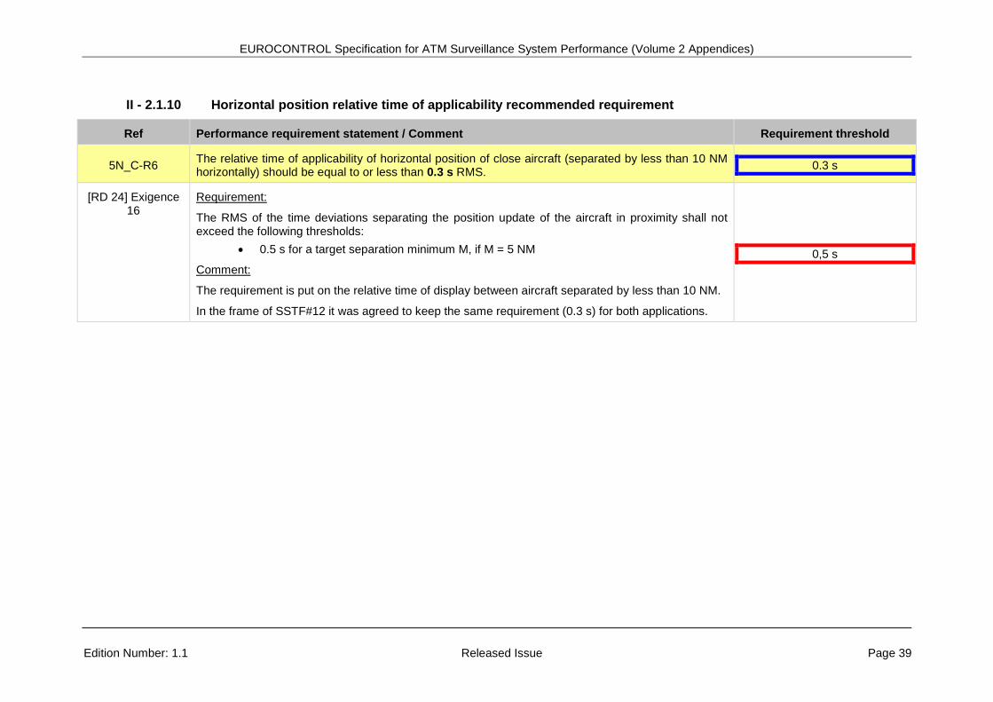
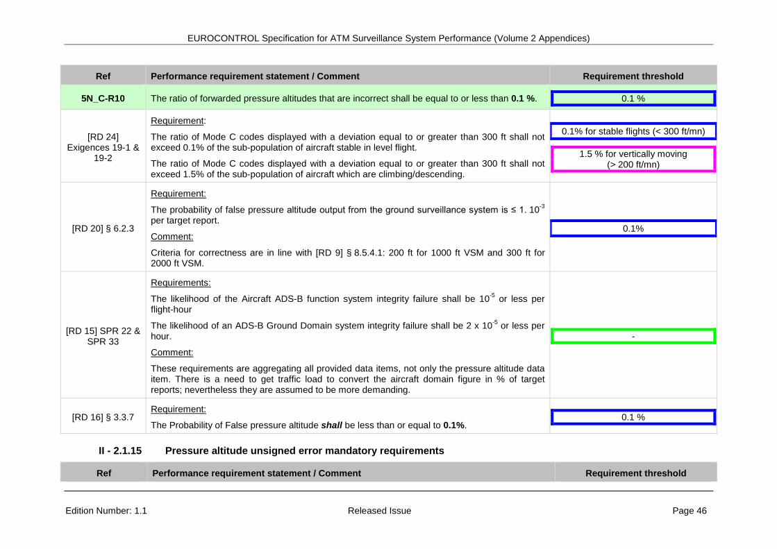
II - 2.1.14 Forwarded pressure altitude correctness
5N_C-R10 The ratio of forwarded pressure altitudes that are incorrect shall be equal to or less than 0.1 %. 0.1 %
[RD 9] § 8.5.4.1 Statement:
If the ATC displayed Mode C differs of more than 200 ft (1000 ft vertical separation) / 300 ft (2000 ft vertical separation) the controller shall verify the correctness of Mode C with the pilot.
[RD 2] § 6.3.3.2
Requirement:
Validated false Mode C codes: < 0.1 %
Comment:
For SSR only, in SASS-C the threshold to declare incorrect Mode C is set to 300 ft.
0.1 %
[RD 14] SPR 10 § 3.4.2 &
SPR 13 § 3.5.2
Requirements:
The likelihood that the Aircraft Transmit Domain corrupts ADS-B information shall be no more than 10-5 per flight-hour
The likelihood that the ADS-B receive subsystem corrupts ADS-B information through the reception, processing or delivery of data (E2) shall be no more than 5 x 10⁻⁶ per ATSU hour.
Comment:
These requirements are aggregating all provided data items, not only the pressure altitude data item. There is a need to get traffic load to convert these figures in %; nevertheless they are assumed to be more demanding.
?
EUROCONTROL Specification for ATM Surveillance System Performance (Volume 2 Appendices)
5N_C-R10 The ratio of forwarded pressure altitudes that are incorrect shall be equal to or less than 0.1 %. 0.1 %
[RD 24] Exigences 19-1 &
19-2
Requirement:
The ratio of Mode C codes displayed with a deviation equal to or greater than 300 ft shall not exceed 0.1% of the sub-population of aircraft stable in level flight.
The ratio of Mode C codes displayed with a deviation equal to or greater than 300 ft shall not exceed 1.5% of the sub-population of aircraft which are climbing/descending.
0.1% for stable flights (< 300 ft/mn)
1.5 % for vertically moving (> 200 ft/mn)
[RD 20] § 6.2.3
Requirement:
The probability of false pressure altitude output from the ground surveillance system is ≤ 1. 10-3 per target report.
Comment:
Criteria for correctness are in line with [RD 9] § 8.5.4.1: 200 ft for 1000 ft VSM and 300 ft for 2000 ft VSM.
0.1%
[RD 15] SPR 22 & SPR 33
Requirements:
The likelihood of the Aircraft ADS-B function system integrity failure shall be 10-5 or less per flight-hour
The likelihood of an ADS-B Ground Domain system integrity failure shall be 2 x 10⁻⁵ or less per hour.
Comment:
These requirements are aggregating all provided data items, not only the pressure altitude data item. There is a need to get traffic load to convert the aircraft domain figure in % of target reports; nevertheless they are assumed to be more demanding.
-
[RD 16] § 3.3.7 Requirement:
The Probability of False pressure altitude shall be less than or equal to 0.1%. 0.1 %
II - 2.1.15 Pressure altitude unsigned error mandatory requirements
EUROCONTROL Specification for ATM Surveillance System Performance (Volume 2 Appendices)
Edition Number: 1.1 Released Issue Page 47
5N_C-R11 The pressure altitude unsigned error shall be less than or equal to 200/300 ft in 99.9% of the cases for stable flights and less than or equal to 300 ft in 98.5% of the cases for climbing / descending flights.
99.9 % 98.5 %
[RD 24] Exigences 19-1 and 19-2
This requirement is an alternative to the requirements addressing forwarded pressure altitude data age and correctness. It limits the error on pressure altitude, at its time of display, in the same way as the horizontal position error.
99.9 % 98.5 %
SSTF #17 At SSTF #17 it was agreed to put a maximum limit to the vertical speed of 8000 ft/mn and to not address pressure altitude data items corresponding to portion of trajectories exceeding 8000 ft/mn as climbing of descending rate.
Usually the pressure altitude that is provided to the users is the last measured altitude (see § 5.2.5 [RD 2]) because an extrapolated altitude is not enough reliable. However new systems could provide reliable calculated pressure altitude and a new requirement is now defined to cover this type of implementation.
[RD 9] § 8.5.5.1.1-2
For stable flights inside RVSM, respectively non-RVSM, airspace the threshold has been set to 200 ft, respectively 300 ft, because of the requirements specified in ICAO document 4444 [RD 9] § 8.5.5.1.1-2 where it is stated:
“8.5.5.1.1 The tolerance value used to determine that pressure-altitude-derived level information displayed to the controller is accurate shall be ±60 m (±200 ft) in RVSM airspace. In other airspace, it shall be ±90 m (±300 ft), except that the appropriate ATS authority may specify a smaller criterion, but not less than ±60 m (±200 ft), if this is found to be more practical. Geometric height information shall not be used for separation.
8.5.5.1.2 Verification of pressure-altitude-derived level information displayed to the controller shall be effected at least once by each suitably equipped ATC unit on initial contact with the aircraft concerned or, if this is not feasible, as soon as possible thereafter. The verification shall be effected by simultaneous comparison with altimeter-derived level information received from the same aircraft by radiotelephony. The pilot of the aircraft whose pressure-altitude-derived level information is within the approved tolerance value need not be advised of such verification. Geometric height information shall not be used to determine if altitude differences exist.”
It is assumed that when an aircraft is transferred from one ATC centre to another it stays at a stable flight level.
EUROCONTROL Specification for ATM Surveillance System Performance (Volume 2 Appendices)
5N_C-R11 The pressure altitude unsigned error shall be less than or equal to 200/300 ft in 99.9% of the cases for stable flights and less than or equal to 300 ft in 98.5% of the cases for climbing / descending flights.
99.9 % 98.5 %
[RD 9] § 8.5.5.2.3-4
For climbing/descending flights, and irrespective of the airspace, the threshold has been set to 300 ft because of the requirements specified in ICAO document 4444 [RD 9] § 8.5.5.2.3-4 where it is stated:
“8.5.5.2.3 Aircraft vacating a level. An aircraft cleared to leave a level is considered to have commenced its manoeuvre and vacated the previously occupied level when the pressure-altitude-derived level information indicates a change of more than 90 m (300 ft) in the anticipated direction from its previously assigned level.
8.5.5.2.4 Aircraft passing a level in climb or descent. An aircraft in climb or descent is considered to have crossed a level when the pressure-altitude-derived level information indicates that it has passed this level in the required direction by more than 90 m (300 ft).”
II - 2.1.16 Change in emergency indicator/SPI report delay mandatory requirements
5N_C-R12 The time between the emergency indicator / SPI report being present at sensor level for the first time and availability of the emergency indicator / SPI report at the output of the surveillance system shall be equal to or less than 12 s.
12 s
SSTF#14 Calculations have been made on the basis of single radar and multi-radar tracker configurations and the figure of 12 s has been agreed for this requirement. 12 s
SSTF#21 At SSTF #21 it was agreed that this delays must be applicable for 100% of the cases, however it is also recognised that cases of higher delay may happen in rare cases. These cases should be analysed to avoid/minimise their re-occurence.
12 s
[RD 2] § 6.7 Requirement:
The maximum target report delay shall be less than or equal to 2 seconds. 2 s
[RD 14] SPR 12 § 3.4.2.2 – SPR 16
§ 3.5.2
Requirement:
For barometric altitude, aircraft identification, mode A code, SPI and Emergency indicators, the 0.5 s at 95%
EUROCONTROL Specification for ATM Surveillance System Performance (Volume 2 Appendices)
5N_C-R12 The time between the emergency indicator / SPI report being present at sensor level for the first time and availability of the emergency indicator / SPI report at the output of the surveillance system shall be equal to or less than 12 s.
12 s
Airborne Transmit Domain shall have a latency no greater than specified in current implementations for SSR.
The 95% latency for ADS-B Surveillance Reports (measured between points D and E2) shall be no greater than 0.5s.
[RD 15] SPR 35 § 3.4.2
Requirement: The 95% latency for ADS-B surveillance reports (measured between points D and E2 (output of the “Ground ADS-B Receive” function) shall be no greater than 0.5 seconds, excluding communication latency to the ATC processing system.
0.5 s at 95%
[RD 16] § 3.3.11 Requirement: In Periodic Delayed Mode, when the last received measured position within the Output Period is transmitted, the maximum Processing delay shall be less than or equal to the duration of the Output Period plus 1s.
Max 9 s
EUROCONTROL Specification for ATM Surveillance System Performance (Volume 2 Appendices)
Edition Number: 1.1 Released Issue Page 50
II - 2.1.17 Change in aircraft identity delay mandatory requirements
5N_C-R13 The time between the second occurrence at sensor level of the new aircraft identity and the availability of the new aircraft identity at the output of the surveillance system shall be equal to or less than 24 s.
24 s
SSTF #12-15
The objective of this requirement is to limit the latency of a change of aircraft identity (forwarded data item) inside the surveillance system. There is currently no equivalent requirement in any standard (except SPR 25 in [RD 14]) from which this requirement can be traced. The inclusion of the requirement was agreed at SSTF meeting #12 and the threshold value was agreed during STTF meeting #15.
24 s
SSTF #21 At SSTF #21 it was agreed that this delays must be applicable for 100% of the cases, however it is also recognised that cases of higher delay may happen in rare cases. These cases shall be analysed to avoid/minimise their re-occurence.
24 s
[RD 2] § 6.7 Requirement:
The maximum target report delay shall be less than or equal to 2 seconds. 2 s
[RD 14] SPR 12 § 3.4.2.2 –
SPR 16 § 3.5.2
Requirement:
For barometric altitude, aircraft identification, mode A code, SPI and Emergency indicators, the Airborne Transmit Domain shall have a latency no greater than specified in current implementations for SSR.
The 95% latency for ADS-B Surveillance Reports (measured between points D and E2) shall be no greater than 0.5s.
0.5 s at 95%
[RD 15] SPR 35 § 3.4.2
Requirement: The 95% latency for ADS-B surveillance reports (measured between points D and E2 (output of the “Ground ADS-B Receive” function) shall be no greater than 0.5 seconds, excluding communication latency to the ATC processing system.
0.5 s at 95%
[RD 16] § 3.3.11 Requirement: In Periodic Delayed Mode, when the last received measured position within the Output Period is transmitted, the maximum Processing delay shall be less than or equal to the duration of the Output Period plus 1s.
Max 9 s
EUROCONTROL Specification for ATM Surveillance System Performance (Volume 2 Appendices)
5N_C-R13 The time between the second occurrence at sensor level of the new aircraft identity and the availability of the new aircraft identity at the output of the surveillance system shall be equal to or less than 24 s.
24 s
[RD 27] § 1.2.2.1.1.3
Requirement:
Any change of Identity shall be reported at the output of the surveillance system in less than 20s. 20 s
[RD 15] SPR 51
Requirements:
For 5 NM separation – The time interval between a change of Mode A code provided by the ADS-B aircraft domain and an ADS-B surveillance report containing the new Mode A code at interface E2 shall be no longer than 8 seconds (95%) En Route.
Comment:
Interface E2 is between Ground ADS-B Receive Function and Ground ADS-B Surveillance Processing Function. Interface E2 is inside the ADS-B Ground Domain, therefore the performance at the ATCO level should be worse. It is not possible to compare these requirements.
8 s
EUROCONTROL Specification for ATM Surveillance System Performance (Volume 2 Appendices)
Edition Number: 1.1 Released Issue Page 52
II - 2.1.18 Correct aircraft identity probability of update mandatory requirement
5N_C-R14 The probability of update of correct aircraft identity (Mode A or aircraft identification) shall equal or greater than 98% globally. 98 %
SSTF #19 At SSTF #19 it has been agreed that this type of requirement was lacking and the value of 98 % was agreed. 98 %
[RD 2] § 6.3.2.4
Requirement:
Overall Mode A probability of code detection: > 98 %
Comment:
For 1 SSR only and for Mode A only.
98 %
[RD 15] SPR 49
Requirement:
For 5 NM separation – The probability of providing a Surveillance Report containing newly received ADS-B Position data of sufficient quality associated with any aircraft in En Route airspace within 8 seconds shall be 97%.
Comment:
For ADS-B only. It is assumed that “ADS-B Position data” encompasses all the data items listed in SPR 27 which include aircraft identity. As the requirement is on the proportion of target reports with horizontal position therefore the achieved ADS-B performance should be 100 % minus the cases of pressure altitude integrity error.
100 - %
[RD 16] § 2.8.2 Requirement:
The WAM system shall provide a correct and validated Mode A code within the defined Measurement interval with a probability greater than or equal to 98%.
98 %
[RD 3] § 4.2.4.1.4 Requirement:
As a minimum, the overall Mode 3/A probability of correct and valid code detection shall be better than 98% for large samples, without any geographical restrictions, of opportunity traffic.
98 %
EUROCONTROL Specification for ATM Surveillance System Performance (Volume 2 Appendices)
Edition Number: 1.1 Released Issue Page 53
II - 2.1.19 Correct aircraft identity probability of update mandatory requirement
5N_C-R15 The ratio of aircraft identities that are incorrect shall be equal to or less than 0.1 %. 0.1 %
[RD 2] § 6.3.3.2
Requirement:
Validated false Mode A codes: < 0.1 %
Comment:
For SSR only and for Mode A only.
0.1 %
[RD 14] SPR 10 § 3.4.2 &
SPR 13 § 3.5.2
Requirements:
The likelihood that the Aircraft Transmit Domain corrupts ADS-B information shall be no more than 10-5 per flight-hour
The likelihood that the ADS-B receive subsystem corrupts ADS-B information through the reception, processing or delivery of data (E2) shall be no more than 5. 10-6 per ATSU hour.
Comment:
These requirements are aggregating all provided data items, not only the aircraft identity data item. There is a need to get traffic load to convert these figures in %; nevertheless they are assumed to be more demanding.
?
EUROCONTROL Specification for ATM Surveillance System Performance (Volume 2 Appendices)
5N_C-R15 The ratio of aircraft identities that are incorrect shall be equal to or less than 0.1 %. 0.1 %
[RD 20] § 7.2.3 Proposed requirement:
The probability of an incorrect identification data output from ground system is ≤ 1x10⁻³ per target report.
0.1 %
[RD 15] SPR 22 & SPR 33
Requirements:
The likelihood of the Aircraft ADS-B function system integrity failure shall be 10-5 or less per flight-hour
The likelihood of an ADS-B Ground Domain system integrity failure shall be 2 x 10⁻⁵ or less per hour.
Comment:
These requirements are aggregating all provided data items, not only the aircraft identity data item. There is a need to get traffic load to convert the aircraft domain figure in % of target reports; nevertheless they are assumed to be more demanding.
-
[RD 16] § 3.3.7
Requirement:
The Probability of False Mode A code detection shall be less than or equal to 0.1%.
The Probability of False ACID detection shall be less than or equal to 0.1%.
0.1 %
EUROCONTROL Specification for ATM Surveillance System Performance (Volume 2 Appendices)
Edition Number: 1.1 Released Issue Page 56
II - 2.1.21 Rate of climb/descent error recommended requirement
5N_C-R16 The RMS error of the rate of climb/descent should be equal to or less than 250 ft/mn for stable flights and should be equal or less than 500 ft/mn for climbing/descending flights.
SSTF #12-15 The objective of this requirement is to specify the error on the rate of climb/descent. There is currently no equivalent requirement in any standard from which this requirement can be traced from. The initial value proposed at SSTF #12 has been reviewed at SSTF #15and has been found feasible.
SSTF #17 At SSTF #17 it was agreed to limit the assessment to climbing and descending rates that are below 8000 ft/mn.
SSTF #19 At SSTF #19 on the basis of the measurements presented by DSNA/DTI it was agreed to differentiate between stable flights and climbing/descending flights on the same basis as for the accuracy of the pressure altitude data item. It was also agreed to calculate the RMS error rather than the average error which is a more relevant parameter to report on the accuracy of the pressure rate.
The RMS error of the track velocity and track velocity angle should be, respectively, equal to or less than 4 m/s and 10 ° for portions of trajectories in straight line and equal to or less than 8 m/s and 25 ° for portions of trajectories in turn.
4/8 m/s 10/25 °
SSTF #17
The objective of this requirement is to specify the error on the track velocity when this data item is provided by the surveillance system. The same value as for 3 NM separation (based on actual system performance) have been used although the speed accuracy should be worse in the case of 5 NM separation because of the longer measurement interval but on the other side it should be better because in this airspace the aircraft are less manoeuvring and there is also a higher level of sensor overlapping coverage in that airspace.
4/8 m/s 10/25 °
EUROCONTROL Specification for ATM Surveillance System Performance (Volume 2 Appendices)
Edition Number: 1.1 Released Issue Page 58
II - 2.1.23 Uncorrelated false target report mandatory requirement
5N_C-R19 The density of uncorrelated false target reports per area of 900 NM2 and over a duration of 450 applicable measurement intervals (450 updates periods of 8 s equal 1 hour) shall be less than or equal to 10.
10
[RD 2] § 6.3.2.2 & 6.3.2.3
Requirement:
Overall false target report ratio: < 0.1 %
Overall multiple SSR target report ratio: < 0.3 %
Comment:
Derived from SSR only requirements and aggregating all sources of false plots (false and multiple). Although the requirement is not expressed in a similar way, it seems less demanding.
0.4 %
[RD 14] SPR 10 § 3.4.2 &
SPR 13 § 3.5.2
Requirements:
The likelihood that the Aircraft Transmit Domain corrupts ADS-B information shall be no more than 10-5 per flight-hour.
The likelihood that the ADS-B receive subsystem corrupts ADS-B information through the reception, processing or delivery of data (E2) shall be no more than 5. 10-6 per ATSU hour.
Comments:
Although it is not possible to convert the above figure in accordance with the specified indicator, that requirement is deemed more demanding.
-
EUROCONTROL Specification for ATM Surveillance System Performance (Volume 2 Appendices)
5N_C-R19 The density of uncorrelated false target reports per area of 900 NM2 and over a duration of 450 applicable measurement intervals (450 updates periods of 8 s equal 1 hour) shall be less than or equal to 10.
10
[RD 21] § 6.4 Approach #3 En route airspace
Requirements:
The number of false target reports per area of 900 NM2 and per time interval of 30 minutes shall be less than or equal to 5.
Comments:
This requirement has been defined on the basis of user requirements and on the basis of assessments made on few datasets. It requires further analysis to confirm its applicability and relevance. For consistency the requirement has been expressed per hour.
At SSTF #19 it was agreed to convert the duration in a number of measurement interval to normalise the requirement irrespective of the applicable measurement interval. The number of measurement interval being equal to 1 hour divided by the maximum allowed measurement interval.
5 false target reports per 900 NM2 and per 30 min
EUROCONTROL Specification for ATM Surveillance System Performance (Volume 2 Appendices)
5N_C-R19 The density of uncorrelated false target reports per area of 900 NM2 and over a duration of 450 applicable measurement intervals (450 updates periods of 8 s equal 1 hour) shall be less than or equal to 10.
10
[RD 15] SPR 14, SPR 22 & SPR 33
Requirements:
The probability that a horizontal position error exceeds the integrity containment bounds for more than 10 seconds without reflecting the fact at B1 shall be no greater than 0.001.
The likelihood of the aircraft ADS-B function system integrity failure shall be 10-5 or less per flight hour.
The likelihood of an ADS-B Ground Domain system integrity failure shall be 2 x 10⁻⁵ or less per hour.
Comment:
The first requirement is provided per flight hour (to be clarified/confirmed) and for a containment radius of 1 NM (close to the 2100 m maximum error). The second requirement is not specific to horizontal position data item, so the probability of integrity failure of horizontal position mad by the ground system should be smaller. Nevertheless, assuming that 900 NM² is the size of a sector and the high density traffic characteristics defined in [RD 15] (6 flight hours per sector and per hour) this requirement is more demanding (less than 0.00606 false target report per hour and per sector).
0.00606
SSTF #19
At SSTF #19, it was agreed to specify the duration not as an absolute value but as a number of applicable measurement intervals so as to normalise the requirement irrespective of the applicable measurement interval. Therefore a value of 450 measurement intervals was agreed corresponding to one hour when measurement interval is 8 s.
EUROCONTROL Specification for ATM Surveillance System Performance (Volume 2 Appendices)
Edition Number: 1.1 Released Issue Page 61
II - 2.1.24 Falsely confirmed track mandatory requirement
5N_C-R20 The number of coincident falsely confirmed tracks close to true tracks (less than 7 NM) shall be less than or equal to 2 per hour and not coincident. 2
[RD 21] § 6.4 Approach #4 TMA airspace
Requirements:
The number of false tracks close to true tracks (less than 7 NM) shall be less than or equal to 2 per hour.
Comments:
This requirement has been defined on the basis of user requirements and on the basis of assessments made on few datasets. It requires further analysis to confirm the figures.
Before SSTF #17 it has been proposed to add the condition that the two false tracks must not appear coincidently.
2 false tracks per hour closer than 7 NM from true tracks
EUROCONTROL Specification for ATM Surveillance System Performance (Volume 2 Appendices)
Edition Number: 1.1 Released Issue Page 62
II - 2.1.25 Ground system continuity recommended requirement
5N_C-R21 The probability of critical failure of the ground surveillance system should be equal to or less than 2.5 10-5 per hour of operation. 2.5 10-5
SSTF #12 It was agreed during SSTF meeting #12. 2.5 10-5
[RD 2] § 5.3.2
Requirement:
The radar surveillance data availability requirements are: • full data availability shall be not less than 0.995, excluding periods of scheduled
maintenance; • essential data availability shall be not less than 0.99999; • PSR data availability for major terminal areas shall be not less than 0.995.
Full data are: • aircraft horizontal position and history; • aircraft identification; • aircraft vertical position; • specific indication of Mode A special codes (i.e. 7500,7600,7700); • ground speed; • status of the Track whether it is primary, secondary, combined or extrapolated.
Essential data are: • aircraft horizontal position and history; • aircraft identification or Mode A code; • aircraft vertical position.
Comment:
It is not possible to convert availability figure to probability of failure. However the requirement on essential data seems more demanding.
?
EUROCONTROL Specification for ATM Surveillance System Performance (Volume 2 Appendices)
5N_C-R21 The probability of critical failure of the ground surveillance system should be equal to or less than 2.5 10-5 per hour of operation. 2.5 10-5
[RD 14] § 3.5.2 SPR 14 & SPR 15
Ground Performance Requirement:
Availability and continuity requirements for ground equipment are left to local authorities. Factors that are recommended to be considered for developing these requirements include traffic density, traffic patterns, and criticality of services being provided. SPR 14: The likelihood that ADS-B Receive subsystem does not provide updated ADS-B surveillance reports for more than one aircraft from which ADS-B messages are being received shall be no more than 5. 10-6 per ATSU hour. SPR 15: The likelihood that the ADS-B receive subsystem does not provide updated ADS-B surveillance reports for one aircraft from which ADS-B messages are being received shall be no more than 10-4 per ATSU hour.
Comment:
For reliability of ADS-B ground only.
See below extract of B.4.4.2 Reliability requirements
Within the context of the ADS-B-NRA application it has been decided to only consider continuity requirements for the ground system. This was done because the scope of the OSED is limited to when aircraft have already entered non-radar airspace. This means that the operation has already commenced, and therefore was “available” at the start of the operation. What is specified in this OPA (and in the SPR requirements in section 3) is the continuity – the likelihood the system will be working normally for the entire flight of any one aircraft through the sector of NRA airspace.
5. 10-6 for at least 2 aircraft
[RD 6] § 8.4.5
Safety Objectives ADS-B-NRA:
Safety objective of sudden and unexpected loss of position information for multiple aircraft previously identified in the sector detected by ATCO is 2.9 10-4 per ATSU hour (severity 3) for En-Route (i.e. 5 NM horizontal separation).
Comment:
This is a safety objective not a performance requirement.
2.9 10-4
EUROCONTROL Specification for ATM Surveillance System Performance (Volume 2 Appendices)
5N_C-R21 The probability of critical failure of the ground surveillance system should be equal to or less than 2.5 10-5 per hour of operation. 2.5 10-5
[RD 7] § 5.3 Safety objective WAM:
Safety objective of detected loss of horizontal position for more than one aircraft is 6. 10-4 per ATSU hour (severity 3) for En-Route (i.e. 5 NM horizontal separation).
6. 10-4
[RD 25] § 4.6 and 7.2
Safety objectives ARTAS software:
Safety objective of total loss of aircraft lateral position information (ARTAS system tracks) within an ARTAS DOI is less than 1. 10-5 per ATSU hour (with fallback system) and less than 1. 10-6 per ATSU hour (without fallback system).
Comment:
This is a safety objective not a performance requirement.
Measured hazard rate on operational ARTAS software:
Hazard: total loss of aircraft lateral position information (ARTAS system tracks) within an ARTAS DOI.
Raw measurement: 2.7 10-5 per ATSU hour (based on 185.000 hours of operation).
Theoretical rate (@ 50% confidence): 3.1 10-5 per ATSU hour.
Theoretical rate (@ 90% confidence): 5. 10-5 per ATSU hour.
1. 10-5
2.7 10-5
[RD 8] § 2.2
Safety objectives Mode S system:
Maximum tolerability of System derived loss of aircraft horizontal position is 3.3 10-9 per flight hour.
Assuming high traffic density it gives a figure of 3.3 10-6 per ATSU hour.
Assuming low/medium traffic density it gives a figure of 3.3 10-7 per ATSU hour.
Comment:
This is a safety objective not a performance requirement.
3.3 10-7
EUROCONTROL Specification for ATM Surveillance System Performance (Volume 2 Appendices)
5N_C-R21 The probability of critical failure of the ground surveillance system should be equal to or less than 2.5 10-5 per hour of operation. 2.5 10-5
[RD 3] § 14.2.2.2
Requirement:
The availability calculation excludes all planned downtimes.
The figures for Availability quoted in this Specification are for Operational Availability (Ao) and shall be calculated using the following equation:
Ao = MTBF / (MTBF + MTTR + MRT) MTBF = Mean Time Between Failures in hours.
MTTR = Mean Time To Repair in hours.
MRT = Mean Response Time in hours (i.e. the average time from notification of failure for a technician to be ready to commence repair action).
The operational availability of coherent and full radar data from the Mode S ground station site shall be greater than 99.98%.
The system reliability requirement for each Mode S ground station as described in Figure 3 (excluding Local Display and Recording/Playback facility) shall be greater than 20,000 hrs MTBF.
MTTR at Organisational Level shall be 30 (thirty) minutes.
The following figures are given for Tender Evaluation purposes:
(a) The MRT shall be 3.5 hours;
(b) The maximum time to repair shall not exceed 8 (eight) hours for 95% of all repairs;
(c) The maximum response time shall not exceed 8 (eight) hours.
Comment:
For a single Mode S sensor taking into account that the probability of failure is equal to 1/MTBF.
5. 10-5
EUROCONTROL Specification for ATM Surveillance System Performance (Volume 2 Appendices)
5N_C-R21 The probability of critical failure of the ground surveillance system should be equal to or less than 2.5 10-5 per hour of operation. 2.5 10-5
[RD 15] SPR 20 & SPR 34
Requirements:
The continuity of the ADS-B Aircraft Domain shall be 0.9998 per flight hour.
The likelihood of a Ground ADS-B Receive function continuity failure shall be 10-5 or less per hour.
Comment:
The probability of failure of the complete system will happen if all the ADS-B Aircraft Domains fail or if the ADS-B ground domain fails. The combined probability equals to (2. 10-4)N + 10-5 where N is the number of aircraft managed by the system. This calculation does not take into account the other components of the ADS-B ground domain. So the continuity of the complete system depends on the continuity of the ground domain which is equal, in the worst case, to 10-
5; the contribution of the aircraft domain is negligible as long as N is greater than 2.
10-5
[RD 16] § 2.8.2
Requirement:
The availability figure defined will typically be met with MTBCF and MTTR figures of 10,000 hours and 1 hour respectively.
Comment:
Indicative figure.
10-4
EUROCONTROL Specification for ATM Surveillance System Performance (Volume 2 Appendices)
Edition Number: 1.1 Released Issue Page 67
II - 2.2 3N_C: 3 NM horizontal separation
II - 2.2.1 Measurement interval mandatory requirements
3N_C-R1 The applicable measurement interval for horizontal position, pressure altitude and aircraft identity data items shall be set to 5 s or less. 5 s
[RD 2] § 5.2.4 Requirement:
Surveillance information updates shall enable the display updates to be no more than 5 seconds (s) for major terminal areas.
5 s
[RD 14] SPR 23 § 3.5.2
Requirement:
For 3 NM separation – The update interval for Surveillance Reports containing any new ADS-B Position data associated with any single aircraft shall be no longer than 5 s with a probability of 95%.
Comment:
For ADS-B only.
5 s
[RD 24] Exigence 18
Requirement:
The duration separating two screen refreshes relating to the same aircraft shall not in principle exceed the following:
• 5 s for a target separation minimum M, if 2 NM < M ≤ 3 NM
5 s
EUROCONTROL Specification for ATM Surveillance System Performance (Volume 2 Appendices)
3N_C-R1 The applicable measurement interval for horizontal position, pressure altitude and aircraft identity data items shall be set to 5 s or less. 5 s
[RD 20] § 6.3.3
Proposed requirement:
The maximum data age of pressure altitude measured at the output of the ground system is: • 1000ft separation = 5s • 2000ft separation = 8s
5 s
[RD 15] SPR 53
Requirement:
For 3 NM separation – The probability of providing a Surveillance Report containing newly received ADS-B Position data of sufficient quality associated with any aircraft in TMA airspace within 5 seconds shall be 97%.
Comment:
For ADS-B only.
5 s
[RD 16] § 3.3.1
Requirement:
The defined Measurement interval shall not exceed the following: • 5 seconds for the TMA application
Comment:
For WAM only.
5 s
EUROCONTROL Specification for ATM Surveillance System Performance (Volume 2 Appendices)
Edition Number: 1.1 Released Issue Page 69
II - 2.2.2 Measurement interval recommended requirements
3N_C-R1 The applicable measurement interval for horizontal position, pressure altitude and aircraft identity data items should be set to 4 s or less. 4 s
SSTF #12 It was agreed during SSTF meeting #12 that to take into account the future traffic increase in Europe it is needed to align the measurement interval for future system to the measurement interval currently applied in high-medium density airspace.
4 s
EUROCONTROL Specification for ATM Surveillance System Performance (Volume 2 Appendices)
Edition Number: 1.1 Released Issue Page 70
II - 2.2.3 Horizontal position and pressure altitude probability of update mandatory requirements
3N_C-R2 The probability of update of the horizontal position and the pressure altitude in accordance with the applicable measurement interval shall be equal to or higher than 97 % per flight. 97 % (per flight)
[RD 2] § 6.3.2.1
Requirement:
Target Position Detection
Overall probability of detection: > 97 %
Comment:
For 1 SSR only.
For 2 independent SSR’s the requirement should be 99.91 %.
There is no requirement per flight; therefore it is not possible to compare them with the requirement above.
97 % or 99.91 % (globally)
[RD 14] SPR 23 § 3.5.2
Requirement:
For 3 NM separation – The update interval for Surveillance Reports containing any new ADS-B Position data associated with any single aircraft shall be no longer than 5 s with a probability of 95%.
95 % (per flight)
EUROCONTROL Specification for ATM Surveillance System Performance (Volume 2 Appendices)
3N_C-R2 The probability of update of the horizontal position and the pressure altitude in accordance with the applicable measurement interval shall be equal to or higher than 97 % per flight. 97 % (per flight)
[RD 24] Exigence 18
Requirement:
The duration separating two screen refreshes relating to the same aircraft shall not in principle exceed the following:
• 5 s for a target separation minimum M, if 5 NM < M ≤ 3 NM
Any exceeding of these limits shall be considered individual cases and shall accordingly be the subject of a detailed analysis included in the Radar Separation Minimum Dossier (RSMD).
Such analysis will make it possible to ascertain the cause of the occurrence, the potential operational implications, its classification in the seriousness table, a theoretical estimation of its frequency, the possible proposal of mitigating measures and its acceptability vis-à-vis regulations.
Comment:
According to the above, any missed target report should be very rare as it will require a specific analysis. Although it is not expressed as a probability of update, it is deemed that this requirement is more demanding.
?
[RD 15] SPR 53
Requirement:
For 3 NM separation – The probability of providing a Surveillance Report containing newly received ADS-B Position data of sufficient quality associated with any aircraft in TMA airspace within 5 seconds shall be 97%.
97 % (per flight)
[RD 16] § 3.3.3 Requirement:
The Probability of position detection within the defined Measurement interval shall be greater than or equal to 97% for any target.
97% (per flight)
EUROCONTROL Specification for ATM Surveillance System Performance (Volume 2 Appendices)
Edition Number: 1.1 Released Issue Page 72
II - 2.2.4 Horizontal position and pressure altitude probability of update recommended requirements
3N_C_R2 The probability of update of the horizontal position and the pressure altitude in accordance with the applicable measurement interval (see Req. 01) should be equal to or higher than 99 % globally and equal to or higher than 97 % per flight.
99 % (globally) 97 % (per flight)
SSTF #12
It was agreed during SSTF meeting #12 that to take into account the future traffic increase in Europe it is needed to align the probability of update of positional information for future system to the probability of update of positional information currently achieved in high-medium density airspace.
99 %
SSTF #21 It is proposed to supplement with the mandatory requirement of 97 % per flight with a global requirement of 99 %.
99 % (global) 97 % (per flight)
EUROCONTROL Specification for ATM Surveillance System Performance (Volume 2 Appendices)
Edition Number: 1.1 Released Issue Page 73
II - 2.2.5 Ratio of missed 3D position involved in long gaps mandatory requirement
3N_C-R3 The ratio of missed 3D position (either horizontal position or pressure altitude missing) involved in long gaps (longer than 3 x 5 s + 10% = 16.5 s) shall be equal to or less than 0.5 %. 0.5 %
SSTF #12-15-22
The objective of this requirement is to limit the size of trajectory gaps without full 3D position information. The inclusion of the requirement was agreed at SSTF meeting #12 and the gap size was agreed during STTF meeting #15. At meeting #22 it was agreed to specify an initial value of 0.5 % until more feedback is collected ( see Appendix I - 5).
0.5 %
[RD 16] § 3.3.4
Requirement:
The probability of long position gap for more than 3 times the maximum Measurement interval +10% (26.4 seconds for En-route application and 16.5 seconds for TMA application) shall be less than or equal to 0.1%.
0.1%
EUROCONTROL Specification for ATM Surveillance System Performance (Volume 2 Appendices)
Edition Number: 1.1 Released Issue Page 74
II - 2.2.6 Horizontal position error mandatory requirement
3N_C-R4 Horizontal position error, including measurement error and error due to information latency, shall be equal to or less than 300 m RMS globall and equal to or less than 330 m RMS per flight.
300 m (global)
330 m (per flight)
[RD 2] § 5.2.3
Requirement:
The positional accuracy of the surveillance radar data available, at the control position, shall have an error distribution with a root mean square (RMS) value equal to or less than 300 metres (m) for major terminal areas.
300 m
EUROCONTROL Specification for ATM Surveillance System Performance (Volume 2 Appendices)
3N_C-R4 Horizontal position error, including measurement error and error due to information latency, shall be equal to or less than 300 m RMS globall and equal to or less than 330 m RMS per flight.
300 m (global)
330 m (per flight)
[RD 14] SPR 5 § 3.4.2.1
Requirement:
For ADS-B Airborne, the 95% accuracy of the horizontal position shall be less than 0.3 NM.
Quality indicators that are transmitted in ADS-B messages shall account for any uncompensated latency on-board the aircraft. NOTE1: Quality Indicators, particularly accuracy, as used in this document include all contributing
factors for the uncertainty of position data with respect to the time of applicability for that data. These factors include the uncertainty of the position measurement and any uncompensated latency prior to transmission of the data.
Comment:
Equivalent requirements for ADS-B only (556 m converted in RMS, assuming Rayleigh distribution, gives 321 m), but does not take into account position error due to latency of the information on the ground. There are separated requirements for specifying information latency (Airborne part: less than 1.5 second for 95%, ground part: less than 0.5 second for 95%).
In [RD 14] Appendix B.1.3 it is further stated: “Finally, any uncompensated on-board latency or timing uncertainties that are not known to the ground will have the effect of degrading the position accuracy (predominantly in the along-track direction) of the ADS-B information received by the ground.”
Therefore it is unclear whether or not the error due to uncompensated latency is included or not in the requirement.
This requirement is also to be combined with the data integrity requirements for the airborne (SPR 10 1.10-5 per flight hour) and the ground part (SPR 13 5.10-6 per hour of operation).
321 m (global)
321 m (per flight)
EUROCONTROL Specification for ATM Surveillance System Performance (Volume 2 Appendices)
3N_C-R4 Horizontal position error, including measurement error and error due to information latency, shall be equal to or less than 300 m RMS globall and equal to or less than 330 m RMS per flight.
300 m (global)
330 m (per flight)
[RD 24] Exigence 12
Requirement:
The overall RMS shall not exceed the following thresholds: • 300 m for a target separation minimum of 3 NM
Comment:
It should be noted that the requirement shall also be met when the measurement is made on the basis of turning aircraft trajectories only.
300 m (global)
[RD 17] § 6.4 Tables 15 & 16
Proposed requirement:
Position error standard deviation shall be less than 370 m.
Comment:
Even though it is not possible to convert this value to RMS it is deemed relatively close.
? m
[RD 18] § 10.13 Table 3 & § 10.15
Table 4
Proposed requirement:
Proposed values for 95% containment value is 556 m (0.3 NM) with a standard deviation of 185 m (0.1 NM).
Comment:
Even though it is not possible to convert these values to RMS it is deemed relatively close.
? m
EUROCONTROL Specification for ATM Surveillance System Performance (Volume 2 Appendices)
3N_C-R4 Horizontal position error, including measurement error and error due to information latency, shall be equal to or less than 300 m RMS globall and equal to or less than 330 m RMS per flight.
300 m (global)
330 m (per flight)
[RD 3] § 4.2.6.2 & 4.2.6.3
Requirements:
(i) All SSR Random errors shall be less than 30 m RMS (1 sigma)
(ii) All Mode S Random errors shall be less than 15 m RMS (1 sigma)
All azimuth error standard deviations shall be less than 0.068° (one sigma)
Comment:
For a single Mode S sensor and without taking into account information latency (maximum 2 s).
Assuming no bias and that the azimuth error is Gaussian and is the main component of the position error and taking into account that maximum operational range for 3 NM separation is 80 NM (0.068° represents 176 m at 80 NM).
176 m (global)
EUROCONTROL Specification for ATM Surveillance System Performance (Volume 2 Appendices)
3N_C-R4 Horizontal position error, including measurement error and error due to information latency, shall be equal to or less than 300 m RMS globall and equal to or less than 330 m RMS per flight.
300 m (global)
330 m (per flight)
[RD 15] SPR 12
Requirement:
For 3 NM separation – The 95% accuracy of the measured horizontal position shall be less than 171 metres (NACP = 8).
Comment:
More demanding requirement for ADS-B only (171 m @95% converted in RMS, assuming Rayleigh distribution, gives 99 m), but does not take into account position error due to information latency. There are separated requirements for specifying horizontal position latency (Airborne part: less than 0.6 second (uncompensated) for 95% SPR 24, ground part: less than 0.5 second for 95% SPR 35). It is also stated that these latencies are partially compensated (airborne) or fully compensated (ground), such compensation will introduce a budget error that is not possible to quantify without further assumptions.
99 m (global)
99 m (per flight)
[RD 16] § 3.3.8 & 3.3.11
Requirement:
The Horizontal position errors shall not exceed: • 150 m RMS for the TMA application
NOTE1: The horizontal position error is calculated for the time of applicability provided by the target report.
In Periodic Predicted Mode, when the Predicted Position at time of output is transmitted, the maximum Processing delay shall be 0.5 second.
Comment:
Horizontal position error due to processing delay has to be added.
150 m (global)
EUROCONTROL Specification for ATM Surveillance System Performance (Volume 2 Appendices)
Edition Number: 1.1 Released Issue Page 79
II - 2.2.7 Horizontal position error recommended requirement
3N_C-R4 Horizontal position error, including measurement error and error due to information latency, should be equal to or less than 210 m RMS global and equal to or less than 230 m RMS per flight.
210 m (global)
230 m (per flight)
SSTF #12-19
It was agreed during SSTF meeting #12 that to take into account the future traffic increase in Europe it is needed to align the horizontal position error for future system to the horizontal position error currently achieved in high-medium density airspace.
At SSTF #19 it was agreed to keep the same ratio between the mandatory and the recommended performance requirements for 5 and 3 NM horizontal separation, therefore 200 m agreed at SSTF #12 has been amended as 210 m.
210 m (global)
SSTF #21 At SSTF #21 it was agreed to supplement the global requirement on RMS horizontal position error with a requirement per flight with an additional margin to take account of the limited number of samples when performing an assessment per flight.
230 m (per flight)
EUROCONTROL Specification for ATM Surveillance System Performance (Volume 2 Appendices)
The criteria on horizontal position error for declaring a target report as outlier, including measurement error and error due to information latency, shall be equal to 1690 m. 1690 m
[RD 27] § 1.2.2.1.2.1
Requirement:
Maximum horizontal position error shall be less than half of the chosen separation minimum minus a specified safety buffer.
Note 1: The maximum horizontal position uncertainty is assumed to occur at the end of the update interval.
Comment:
The value of 1690 m has been derived from the 2780 m value assuming a maximum aircraft speed of 400 knots (Volume 1 Annex C - 4.3.2), an update interval of 5 s and an aircraft size of 60 m. This is further illustrated on Figure 13 below.
2780 m
EUROCONTROL Specification for ATM Surveillance System Performance (Volume 2 Appendices)
The criteria on horizontal position error for declaring a target report as outlier, including measurement error and error due to information latency, shall be equal to 1690 m. 1690 m
Figure 13: Maximum horizontal position
Provided that the position error remains in the dark blue area the probability to be in collision during the period of display is null, even in the worst case of the two aircraft heading on. This simple approach does not address the evolution of the aircraft trajectory during the next updates.
Aircraft dimensions:60 m
Uncertainty area due to aircraft movement during
update period:Vmax x update interval
Uncertainty area due to horizontal position error:
Maximum horizontal position error
Horizontal separation
Aircraft dimensions:60 m
Uncertainty area due to aircraft movement during
update period:Vmax x update interval
Uncertainty area due to horizontal position error:
Maximum horizontal position error
Horizontal separation
EUROCONTROL Specification for ATM Surveillance System Performance (Volume 2 Appendices)
Edition Number: 1.1 Released Issue Page 82
II - 2.2.9 Ratio of correlated horizontal position error recommended requirement
3N_C-R5 There should be no more than 0.03 % of position reports included in a series of correlated horizontal position errors in the same direction, larger than 556 m and during more than 3 applicable measurement intervals.
0.03 %
556 m
3 updates
[RD 24] Exigence 5
Requirement:
The ratio of plots with a correlated deviation (i.e. the plots with an across deviation greater than M/10 immediately preceded or followed (i.e. on the preceding or subsequent antenna revolutions) by two plots with an across deviation in the same direction greater than M/20) in the area of interest of the control unit served by the image evaluated shall not exceed 0.03%.
Comment:
M is the applicable separation minima (i.e. 3 NM)
Statement derived from SSR only requirements. The amount of error to declare correlated errors is smaller but is limited to across error.
0.03 %
556-278-278 m
278-278-556 m
3 updates
EUROCONTROL Specification for ATM Surveillance System Performance (Volume 2 Appendices)
Edition Number: 1.1 Released Issue Page 83
II - 2.2.10 Horizontal position relative time of applicability recommended requirement
3N_C-R6 The relative time of applicability of horizontal position of close aircraft (separated by less than 10 NM horizontally) should be equal to or less than 0.3 s RMS. 0.3 s
[RD 24] Exigence 16
Requirement:
The RMS of the time deviations separating the position update of the aircraft in proximity shall not exceed the following thresholds:
• 0.3 s for a target separation minimum M, if 2 NM < M ≤ 3 NM
Comment:
The requirement is put on the relative time of display between aircraft separated by less than 10 NM.
0.3 s
EUROCONTROL Specification for ATM Surveillance System Performance (Volume 2 Appendices)
Edition Number: 1.1 Released Issue Page 84
II - 2.2.11 Correct pressure altitude probability of update mandatory requirement
3N_C-R7 The probability of update of correct pressure altitude in accordance with the applicable measurement interval shall be equal to or higher than 96 %. 96 %
[RD 2] § 6.3.2.4
Requirement:
Overall Mode C probability of code detection: > 96 %
Comment:
For 1 SSR only.
96 %
[RD 14] SPR 19 § 3.5.2
Requirement:
For 5 NM separation – The update interval for Surveillance Reports containing any new ADS-B Position data associated with any single aircraft shall be no longer than 5 s with a probability of 95%.
Comment:
For ADS-B only, it is considered that ADS-B target reports always contain horizontal position and pressure altitude so the ratio should be 100 % minus the cases of pressure altitude integrity error.
100- %
[RD 15] SPR 49
Requirement:
For 5 NM separation – The probability of providing a Surveillance Report containing newly received ADS-B Position data of sufficient quality associated with any aircraft in En Route airspace within 5 seconds shall be 97%.
Comment:
For ADS-B only. It is assumed that “ADS-B Position data” encompasses all the data items listed in SPR 27which include aircraft horizontal position data and pressure altitude so the ratio should be 100 % minus the cases of pressure altitude integrity error.
100- %
[RD 16] § 3.3.3 & 3.3.6
Requirement:
The WAM system shall provide a correct and validated Mode C code within the defined Update interval with a probability greater than or equal to 96%.
96%
EUROCONTROL Specification for ATM Surveillance System Performance (Volume 2 Appendices)
Edition Number: 1.1 Released Issue Page 85
II - 2.2.12 Forwarded pressure altitude average data age mandatory requirements
3N_C-R8 The average data age of the forwarded pressure altitude reported in all target reports shall be equal to or less than 2.5 s. 2.5 s
SSTF #12-15
The objective of this requirement is to limit the latency of pressure altitude (forwarded data item) inside the surveillance system. There is currently no equivalent requirement in any standard from which this requirement can be traced. This value has been proposed during STTF meeting #12 and is based on current surveillance system experience. At SSTF meeting #15 it was reported that some systems are not able to meet this requirement.
2.5 s
[RD 2] § 6.7
Requirement:
The maximum target report delay shall be less than or equal to 2 seconds.
Comment:
Airborne latency is assumed to be negligible, therefore the global performance is better than the above specification.
2 + s
[RD 14] SPR 12 § 3.4.2.2 –
SPR 16 § 3.5.2
Requirement:
For barometric altitude, aircraft identification, mode A code, SPI and Emergency indicators, the Airborne Transmit Domain shall have a latency no greater than specified in current implementations for SSR.
The 95% latency for ADS-B Surveillance Reports (measured between points D and E2) shall be no greater than 0.5s.
Comment:
Airborne and transmission latencies are assumed to be negligible, therefore the global performance is better than the above specification.
0.5 + s
[RD 15] SPR 35 § 3.4.2
Requirement: The 95% latency for ADS-B surveillance reports (measured between points D and E2 – output of the “Ground ADS-B Receive” function) shall be no greater than 0.5 seconds, excluding communication latency to the ATC processing system.
Comment:
0.5 + s
EUROCONTROL Specification for ATM Surveillance System Performance (Volume 2 Appendices)
3N_C-R8 The average data age of the forwarded pressure altitude reported in all target reports shall be equal to or less than 2.5 s. 2.5 s
Airborne latency is assumed to be the same as for SSR (as for NRA) and is therefore negligible, therefore the global performance is better than the above specification.
[RD 16] § 3.3.11
Requirement: In Periodic Delayed Mode, when the last received measured position within the Output Period is transmitted, the maximum Processing delay shall be less than or equal to the duration of the Output Period plus 1s.
Comment:
It is assumed that the WAM system under nominal condition will meet the requirement.
Max 6 s
EUROCONTROL Specification for ATM Surveillance System Performance (Volume 2 Appendices)
Edition Number: 1.1 Released Issue Page 87
II - 2.2.13 Forwarded pressure altitude maximum data age mandatory requirements
3N_C-R9 Any forwarded pressure altitude data item with an age greater than or equal to 16 s shall be considered as not available when assessing R3, R7, R8, R10 and R11 16 s
SSTF #21
Assuming that a large proportion (to be quantified) of the aircraft vertical movements are performed at a rate of climb/descent less than or equal to 3000 ft/mn, 16 s corresponds to the delay for a climbing descending aircraft to leave its initial flight level but to not have yet reached the next (above or below) flight level. In accordance with ICAO Document 4444 [RD 9] an aircraft is at a given flight level if its pressure altitude is within +/- 200 ft from that flight level (VSM = 1000 ft). 16 seconds is derived from 1000 ft minus 200 ft divided by the considered normal vertical speed 3000 ft/mn (or 50 ft/s).
16 s
At SSTF #21 it was agreed that this delays must be applicable for 100% of the cases, however it is also recognised that cases of higher data age may happen in rare cases. These cases shall be analysed to avoid/minimise their re-occurence.
At SSTF #22 it was agreed consider that pressure altitude data items with an age greater than or equal to 16 s shall be considered as not available/present.
[RD 2] § 6.7
Requirement:
The maximum target report delay shall be less than or equal to 2 seconds.
Comment:
Airborne latency is assumed to be negligible, therefore the global performance is better than the above specification.
2 + s
[RD 14] SPR 12 § 3.4.2.2 –
SPR 16 § 3.5.2
Requirement:
For barometric altitude, aircraft identification, mode A code, SPI and Emergency indicators, the Airborne Transmit Domain shall have a latency no greater than specified in current implementations for SSR.
The 95% latency for ADS-B Surveillance Reports (measured between points D and E2) shall be no greater than 0.5s.
Comment:
Airborne and transmission latencies are assumed to be negligible, therefore the global performance is
0.5 + s
EUROCONTROL Specification for ATM Surveillance System Performance (Volume 2 Appendices)
3N_C-R9 Any forwarded pressure altitude data item with an age greater than or equal to 16 s shall be considered as not available when assessing R3, R7, R8, R10 and R11 16 s
better than the above specification.
[RD 15] SPR 35 § 3.4.2
Requirement: The 95% latency for ADS-B surveillance reports (measured between points D and E2 – output of the “Ground ADS-B Receive” function) shall be no greater than 0.5 seconds, excluding communication latency to the ATC processing system.
Comment:
Airborne latency is assumed to be the same as for SSR (as for NRA) and is therefore negligible, therefore the global performance is better than the above specification.
0.5 + s
[RD 16] § 3.3.11
Requirement: In Periodic Delayed Mode, when the last received measured position within the Output Period is transmitted, the maximum Processing delay shall be less than or equal to the duration of the Output Period plus 1s.
Max 6 s
EUROCONTROL Specification for ATM Surveillance System Performance (Volume 2 Appendices)
Edition Number: 1.1 Released Issue Page 89
II - 2.2.14 Forwarded pressure altitude correctness
3N_C-R10 The ratio of forwarded pressure altitudes that are incorrect shall be equal to or less than 0.1 %. 0.1 %
[RD 9] § 8.5.4.1 Statement:
If the ATC displayed Mode C differs of more than 200 ft (1000 ft vertical separation) / 300 ft (2000 ft vertical separation) the controller shall verify the correctness of Mode C with the pilot.
[RD 2] § 6.3.3.2
Requirement:
Validated false Mode C codes: < 0.1 %
Comment:
For SSR only, in SASS-C the threshold to declare incorrect Mode C is set to 300 ft.
0.1 %
[RD 14] SPR 10 § 3.4.2 &
SPR 13 § 3.5.2
Requirements:
The likelihood that the Aircraft Transmit Domain corrupts ADS-B information shall be no more than 10-5 per flight-hour
The likelihood that the ADS-B receive subsystem corrupts ADS-B information through the reception, processing or delivery of data (E2) shall be no more than 5 x 10⁻⁶ per ATSU hour.
Comments:
These requirements are aggregating all provided data items, not only the pressure altitude data item. There is a need to get traffic load to convert these figures in %; nevertheless they are assumed to be more demanding.
?
EUROCONTROL Specification for ATM Surveillance System Performance (Volume 2 Appendices)
3N_C-R10 The ratio of forwarded pressure altitudes that are incorrect shall be equal to or less than 0.1 %. 0.1 %
[RD 24] Exigences 19-1 &
19-2
Requirements:
The ratio of Mode C codes displayed with a deviation equal to or greater than 300 ft shall not exceed 0.1% of the sub-population of aircraft stable in level flight.
The ratio of Mode C codes displayed with a deviation equal to or greater than 300 ft shall not exceed 1.5% of the sub-population of aircraft which are climbing/descending.
0.1% for stable flights (< 300 ft/mn)
1.5 % for vertically moving flights (> 200 ft/mn)
[RD 20] § 6.2.3
Requirements:
The probability of false pressure altitude output from the ground surveillance system is ≤ 1.10-3 per target report.
Comments:
Criteria for correctness are in line with [RD 9] § 8.5.4.1: 200 ft for 1000 ft VSM and 300 ft for 2000 ft VSM.
0.1%
[RD 15] SPR 22 & SPR 33
Requirements:
The likelihood of the Aircraft ADS-B function system integrity failure shall be 10-5 or less per flight-hour
The likelihood of an ADS-B Ground Domain system integrity failure shall be 2 x 10⁻⁵ or less per hour.
Comment:
These requirements are aggregating all provided data items, not only the pressure altitude data item. There is a need to get traffic load to convert the aircraft domain figure in % of target reports; nevertheless they are assumed to be more demanding.
-
[RD 16] § 3.3.7 Requirement:
The Probability of False pressure altitude shall be less than or equal to 0.1%. 0.1 %
EUROCONTROL Specification for ATM Surveillance System Performance (Volume 2 Appendices)
Edition Number: 1.1 Released Issue Page 91
II - 2.2.15 Pressure altitude unsigned error mandatory requirements
3N_C-R11 The pressure altitude unsigned error shall be less than or equal to 200/300 ft in 99.9% of the cases for stable flights and less than or equal to 300 ft in 98.5% of the cases for climbing / descending flights.
99.9 % 98.5 %
[RD 24] Exigences 19-1 and 19-2
It limits the error on pressure altitude, at its time of display, in the same way as the horizontal position error.
99.9 % 98.5 %
SSTF #17 At SSTF #17 it was agreed to put a maximum limit to the vertical speed of 8000 ft/mn and to not address pressure altitude data items corresponding to portion of trajectories exceeding 8000 ft/mn as climbing of descending rate.
Usually the pressure altitude that is provided to the users is the last measured altitude (see § 5.2.5 [RD 2]) because an extrapolated altitude is not enough reliable. However new systems could provide reliable calculated pressure altitude and a new requirement is now defined to cover this type of implementation.
EUROCONTROL Specification for ATM Surveillance System Performance (Volume 2 Appendices)
3N_C-R11 The pressure altitude unsigned error shall be less than or equal to 200/300 ft in 99.9% of the cases for stable flights and less than or equal to 300 ft in 98.5% of the cases for climbing / descending flights.
99.9 % 98.5 %
[RD 9] § 8.5.5.1.1-2
For stable flights inside RVSM, respectively non-RVSM, airspace the threshold has been set to 200 ft, respectively 300 ft, because of the requirements specified in ICAO document 4444 [RD 9] § 8.5.5.1.1-2 where it is stated:
“8.5.5.1.1 The tolerance value used to determine that pressure-altitude-derived level information displayed to the controller is accurate shall be ±60 m (±200 ft) in RVSM airspace. In other airspace, it shall be ±90 m (±300 ft), except that the appropriate ATS authority may specify a smaller criterion, but not less than ±60 m (±200 ft), if this is found to be more practical. Geometric height information shall not be used for separation.
8.5.5.1.2 Verification of pressure-altitude-derived level information displayed to the controller shall be effected at least once by each suitably equipped ATC unit on initial contact with the aircraft concerned or, if this is not feasible, as soon as possible thereafter. The verification shall be effected by simultaneous comparison with altimeter-derived level information received from the same aircraft by radiotelephony. The pilot of the aircraft whose pressure-altitude-derived level information is within the approved tolerance value need not be advised of such verification. Geometric height information shall not be used to determine if altitude differences exist.”
It is assumed that when an aircraft is transferred from one ATC centre to another it stays at a stable flight level.
[RD 9] § 8.5.5.2.3-4
For climbing/descending flights, and irrespective of the airspace, the threshold has been set to 300 ft because of the requirements specified in ICAO document 4444 [RD 9] § 8.5.5.2.3-4 where it is stated:
“8.5.5.2.3 Aircraft vacating a level. An aircraft cleared to leave a level is considered to have commenced its manoeuvre and vacated the previously occupied level when the pressure-altitude-derived level information indicates a change of more than 90 m (300 ft) in the anticipated direction from its previously assigned level.
8.5.5.2.4 Aircraft passing a level in climb or descent. An aircraft in climb or descent is considered to have crossed a level when the pressure-altitude-derived level information indicates that it has passed this level in the required direction by more than 90 m (300 ft).”
EUROCONTROL Specification for ATM Surveillance System Performance (Volume 2 Appendices)
Edition Number: 1.1 Released Issue Page 93
II - 2.2.16 Change in emergency indicator/SPI report delay mandatory requirements
3N_C-R12 The time between the emergency indicator / SPI report being present at sensor level for the first time and availability of the emergency indicator / SPI report at the output of the surveillance system shall be equal to or less than 7.5 s.
7.5 s
SSTF #14 Calculations have been made on the basis of single radar and multi-radar tracker configurations and the figure of 7.5 s has been agreed for this requirement. 7.5 s
SSTF#21 At SSTF #21 it was agreed that this delays must be applicable for 100% of the cases, however it is also recognised that cases of higher delay may happen in rare cases. These cases shall be analysed to avoid/minimise their re-occurence.
7.5 s
[RD 2] § 6.7 Requirement:
The maximum target report delay shall be less than or equal to 2 seconds. 2 s
[RD 14] SPR 12 § 3.4.2.2 –
SPR 16 § 3.5.2
Requirement:
For barometric altitude, aircraft identification, mode A code, SPI and Emergency indicators, the Airborne Transmit Domain shall have a latency no greater than specified in current implementations for SSR.
The 95% latency for ADS-B Surveillance Reports (measured between points D and E2) shall be no greater than 0.5s.
0.5 s at 95%
[RD 15] SPR 35 § 3.4.2
Requirement:
The 95% latency for ADS-B surveillance reports (measured between points D and E2 – output of the “Ground ADS-B Receive” function) shall be no greater than 0.5 seconds, excluding communication latency to the ATC processing system.
0.5 s at 95%
[RD 16] § 3.3.11
Requirement: In Periodic Delayed Mode, when the last received measured position within the Output Period is transmitted, the maximum Processing delay shall be less than or equal to the duration of the Output Period plus 1s.
Max 6 s
EUROCONTROL Specification for ATM Surveillance System Performance (Volume 2 Appendices)
Edition Number: 1.1 Released Issue Page 94
II - 2.2.17 Change in aircraft identity delay mandatory requirements
3N_C-R13 The time between the second occurrence at sensor level of the new aircraft identity and the availability of the new aircraft identity at the output of the surveillance system shall be equal to or less than 15 s
15 s
SSTF #12-15
The objective of this requirement is to limit the latency of a change of aircraft identity (forwarded data item) inside the surveillance system. There is currently no equivalent requirement in any standard (except SPR 25 in [RD 14]) from which this requirement can be traced. The inclusion of the requirement was agreed at SSTF meeting #12 and the threshold value was agreed during STTF meeting #15.
15 s
SSTF#21 At SSTF #21 it was agreed that this delays must be applicable for 100% of the cases, however it is also recognised that cases of higher delay may happen in rare cases. These cases shall be analysed to avoid/minimise their re-occurence.
15 s
[RD 2] § 6.7 Requirement:
The maximum target report delay shall be less than or equal to 2 seconds. 2 s
[RD 14] SPR 12 § 3.4.2.2 –
SPR 16 § 3.5.2
Requirement:
For barometric altitude, aircraft identification, mode A code, SPI and Emergency indicators, the Airborne Transmit Domain shall have a latency no greater than specified in current implementations for SSR.
The 95% latency for ADS-B Surveillance Reports (measured between points D and E2) shall be no greater than 0.5s.
0.5 s at 95%
[RD 15] SPR 35 § 3.4.2
Requirement:
The 95% latency for ADS-B surveillance reports (measured between points D and E2 – output of the “Ground ADS-B Receive” function) shall be no greater than 0.5 seconds, excluding communication latency to the ATC processing system.
0.5 s at 95%
[RD 16] § 3.3.11
Requirement: In Periodic Delayed Mode, when the last received measured position within the Output Period is transmitted, the maximum Processing delay shall be less than or equal to the duration of the Output Period plus 1s.
Max 6 s
EUROCONTROL Specification for ATM Surveillance System Performance (Volume 2 Appendices)
3N_C-R13 The time between the second occurrence at sensor level of the new aircraft identity and the availability of the new aircraft identity at the output of the surveillance system shall be equal to or less than 15 s
15 s
[RD 27] § 1.2.2.1.1.3
Requirement:
Any change of Identity shall be reported at the output of the surveillance system in less than 20s. 20 s
EUROCONTROL Specification for ATM Surveillance System Performance (Volume 2 Appendices)
Edition Number: 1.1 Released Issue Page 96
II - 2.2.18 Correct aircraft identity probability of update mandatory requirement
3N_C-R14 The probability of update of correct aircraft identity (Mode A or aircraft identification) shall equal or greater than 98% globally. 98 %
SSTF #19 At SSTF #19 it has been agreed that this type of requirement was lacking and the value of 98 % was agreed. 98 %
[RD 2] § 6.3.2.4
Requirement:
Overall Mode A probability of code detection: > 98 %
Comment:
For 1 SSR only and for Mode A only.
98 %
[RD 14] SPR 49
Requirement:
For 5 NM separation – The probability of providing a Surveillance Report containing newly received ADS-B Position data of sufficient quality associated with any aircraft in En Route airspace within 8 seconds shall be 97%.
Comment:
For ADS-B only. It is assumed that “ADS-B Position data” encompasses all the data items listed in SPR 27 which include aircraft identity. As the requirement is on the proportion of target reports with horizontal position therefore the achieved ADS-B performance should be 100 % minus the cases of aircraft identity (Mode A or Aircraft Identification) integrity error.
100- %
[RD 16] § 2.8.2 Requirement:
The WAM system shall provide a correct and validated Mode A code within the defined Measurement interval with a probability greater than or equal to 98%.
98 %
[RD 3] § 4.2.4.1.4 Requirement:
As a minimum, the overall Mode 3/A probability of correct and valid code detection shall be better than 98% for large samples, without any geographical restrictions, of opportunity traffic.
98 %
EUROCONTROL Specification for ATM Surveillance System Performance (Volume 2 Appendices)
Edition Number: 1.1 Released Issue Page 97
II - 2.2.19 Correct aircraft identity probability of update mandatory requirement
3N_C-R15 The ratio of aircraft identities that are incorrect shall be equal to or less than 0.1%. 0.1 %
[RD 2] § 6.3.3.2
Requirement:
Validated false Mode A codes: < 0.1 %
Comment:
For SSR only and for Mode A only.
0.1 %
[RD 14] SPR 10 § 3.4.2 &
SPR 13 § 3.5.2
Requirements:
The likelihood that the Aircraft Transmit Domain corrupts ADS-B information shall be no more than 10-5 per flight-hour
The likelihood that the ADS-B receive subsystem corrupts ADS-B information through the reception, processing or delivery of data (E2) shall be no more than 5. 10-6 per ATSU hour.
Comments:
These requirements are aggregating all provided data items, not only the aircraft identity data item. There is a need to get traffic load to convert these figures in %; nevertheless they are assumed to be more demanding.
?
EUROCONTROL Specification for ATM Surveillance System Performance (Volume 2 Appendices)
3N_C-R15 The ratio of aircraft identities that are incorrect shall be equal to or less than 0.1%. 0.1 %
[RD 20] § 7.2.3 Proposed requirement:
The probability of an incorrect identification data output from ground system is ≤ 1x10⁻³ per target report.
0.1 %
[RD 15] SPR 22 & SPR 33
Requirements:
The likelihood of the Aircraft ADS-B function system integrity failure shall be 10-5 or less per flight-hour
The likelihood of an ADS-B Ground Domain system integrity failure shall be 2 x 10⁻⁵ or less per hour.
Comment:
These requirements are aggregating all provided data items, not only the aircraft identity data item. There is a need to get traffic load to convert the aircraft domain figure in % of target reports; nevertheless they are assumed to be more demanding.
-
[RD 16] § 3.3.7
Requirement:
The Probability of False Mode A code detection shall be less than or equal to 0.1%.
The Probability of False ACID detection shall be less than or equal to 0.1%.
0.1 %
EUROCONTROL Specification for ATM Surveillance System Performance (Volume 2 Appendices)
Edition Number: 1.1 Released Issue Page 100
II - 2.2.21 Rate of climb/descent error recommended requirement
3N_C-R16 The RMS error of the rate of climb/descent should be equal to or less than 250 ft/mn for stable flights and should be equal or less than 500 ft/mn for climbing/descending flights.
SSTF #15 The objective of this requirement is to specify the error on the rate of climb/descent. There is currently no equivalent requirement in any standard from which this requirement can be trace from. The inclusion of the requirement based on the average error was agreed at SSTF meeting #12 and the threshold (300 ft/mn) value was agreed during STTF meeting #15.
SSTF #17 At SSTF #17 it was agreed to limit the assessment to climbing and descending rates that are below 8000 ft/mn.
SSTF #19 At SSTF #19 on the basis of the measurements presented by DSNA/DTI it was agreed to differentiate between stable flights and climbing/descending flights on the same basis as for the accuracy of the pressure altitude data item. It was also agreed to calculate the RMS error rather than the average error which is a more relevant parameter to report on the accuracy of the pressure rate.
The RMS error of the track velocity and angle should be, respectively, equal to or less than 4 m/s and 10 ° for portions of trajectories in straight line and equal to or less than 8 m/s and 25 ° for portions of trajectories in turn.
4/8 m/s 10/25 °
SSTF #17 The objective of this requirement is to specify the error on the track velocity when this data item is provided by the surveillance system. These figures have been derived from the performance achieved by systems in operation providing 3 NM horizontal separation.
4/8 m/s 10/25 °
EUROCONTROL Specification for ATM Surveillance System Performance (Volume 2 Appendices)
Edition Number: 1.1 Released Issue Page 102
II - 2.2.23 Uncorrelated false target report mandatory requirement
3N_C-R19 The density of uncorrelated false target reports per area of 100 NM2 and over a duration of 720 applicable measurement intervals shall be less than or equal to 2. 2
[RD 2] § 6.3.2.2 & 6.3.2.3
Requirement:
Overall false target report ratio: < 0.1 %
Overall multiple SSR target report ratio: < 0.3 %
Comment:
Derived from SSR only requirements and aggregating all sources of false plots (false and multiple).
0.4 %
[RD 14] SPR 10 § 3.4.2 &
SPR 13 § 3.5.2
Requirements:
The likelihood that the Aircraft Transmit Domain corrupts ADS-B information shall be no more than 10-5 per flight-hour
The likelihood that the ADS-B receive subsystem corrupts ADS-B information through the reception, processing or delivery of data (E2) shall be no more than 5. 10-6 per ATSU hour.
Comments:
Although it is not possible to convert the above figure in accordance with the specified indicator, that requirement is deemed more demanding.
0.05
EUROCONTROL Specification for ATM Surveillance System Performance (Volume 2 Appendices)
3N_C-R19 The density of uncorrelated false target reports per area of 100 NM2 and over a duration of 720 applicable measurement intervals shall be less than or equal to 2. 2
[RD 21] § 6.4 Approach #3 En route airspace
Requirements:
The number of false target reports per area of 100 NM2 and per 30 minutes shall be less than or equal to 1.
Comments:
This requirement has been defined on the basis of user requirements and on the basis of assessments made on few datasets. It requires further analysis to confirm its applicability and relevance. For consistency the requirement has been converted per hour.
At SSTF #19 it was agreed to convert the duration in a number of applicable measurement interval to normalise the requirement irrespective of the applicable measurement interval. The number of measurement interval being equal to 1 hour divided by the maximum allowed measurement interval.
1 false target reports per 100 NM2 and per 30 min
EUROCONTROL Specification for ATM Surveillance System Performance (Volume 2 Appendices)
3N_C-R19 The density of uncorrelated false target reports per area of 100 NM2 and over a duration of 720 applicable measurement intervals shall be less than or equal to 2. 2
[RD 15] SPR 14, SPR 22 & SPR 33
Requirements:
The probability that a horizontal position error exceeds the integrity containment bounds for more than 10 seconds without reflecting the fact at B1 shall be no greater than 0.001 (per flight hour)
The likelihood of aircraft ADS-B function system integrity failure shall be 1 x 10⁻⁵ or less per flight hour.
The likelihood of an ADS-B Ground Domain system integrity failure shall be 2 x 10⁻⁵ or less per hour.
Comment:
The first requirement is provided per flight hour (to be clarified/confirmed) and for a containment radius of 0.6 NM (less than the 1700 m maximum error). The second and third requirements are not specific to horizontal position data item, so the probability of integrity failure of horizontal position made by the total system should be smaller. Nevertheless, assuming that 100 NM² is the size of a sector and the high density traffic characteristics defined in [RD 15] (6 flight hours per sector and per hour) this requirement is more demanding (less than 0.00606 false target report per hour and per sector).
0.00606
SSTF #19
At SSTF #19, it was agreed to specify the duration not as an absolute value but as a number of applicable measurement intervals so as to normalise the requirement irrespective of the applicable measurement interval. Therefore a value of 720 measurement intervals was agreed corresponding to one hour when measurement interval is 5 s.
EUROCONTROL Specification for ATM Surveillance System Performance (Volume 2 Appendices)
Edition Number: 1.1 Released Issue Page 105
II - 2.2.24 Falsely confirmed track mandatory requirement
3N_C-R20 The number of false tracks close to true tracks (less than 9 NM) shall be less than or equal to 1 per hour. 1
[RD 21] § 6.4 Approach #4 TMA
airspace
Requirements:
The number of false tracks close to true tracks (less than 9 NM) shall be less than or equal to 1 per hour.
Comments:
This requirement has been defined on the basis of user requirements and on the basis of assessments made on few datasets. It requires further analysis to confirm the figures.
1 false track per hour closer than 9 NM from true tracks
EUROCONTROL Specification for ATM Surveillance System Performance (Volume 2 Appendices)
Edition Number: 1.1 Released Issue Page 106
II - 2.2.25 Ground system continuity recommended requirement
3N_C-R21 The probability of critical failure of the ground surveillance system should be equal to or less than 2.5 10-5 per hour of operation. 2.5 10-5
SSTF #12 It was agreed during SSTF meeting #12. 2.5 10-5
[RD 2] § 5.3.2
Requirement:
The radar surveillance data availability requirements are: • full data availability shall be not less than 0.995, excluding periods of scheduled
maintenance; • essential data availability shall be not less than 0.99999; • PSR data availability for major terminal areas shall be not less than 0.995.
Full data are : • aircraft horizontal position and history; • aircraft identification; • aircraft vertical position; • specific indication of Mode A special codes (i.e. 7500,7600,7700); • ground speed; • status of the Track whether it is primary, secondary, combined or extrapolated.
Essential data are: • aircraft horizontal position and history; • aircraft identification or Mode A code; • aircraft vertical position.
Comment:
It is not possible to convert availability figure to probability of failure. However the requirement on essential data seems more demanding.
?
EUROCONTROL Specification for ATM Surveillance System Performance (Volume 2 Appendices)
3N_C-R21 The probability of critical failure of the ground surveillance system should be equal to or less than 2.5 10-5 per hour of operation. 2.5 10-5
[RD 14] § 3.5.2 SPR 14 & SPR 15
Ground Performance Requirement:
Availability and continuity requirements for ground equipment are left to local authorities. Factors that are recommended to be considered for developing these requirements include traffic density, traffic patterns, and criticality of services being provided. SPR 14: The likelihood that ADS-B Receive subsystem does not provide updated ADS-B surveillance reports for more than one aircraft from which ADS-B messages are being received shall be no more than 5. 10-6 per ATSU hour. SPR 15: The likelihood that the ADS-B receive subsystem does not provide updated ADS-B surveillance reports for one aircraft from which ADS-B messages are being received shall be no more than 10-4 per ATSU-hour.
Comment:
For reliability of ADS-B ground only.
See below extract of B.4.4.2 Reliability requirements
Within the context of the ADS-B-NRA application it has been decided to only consider continuity requirements for the ground system. This was done because the scope of the OSED is limited to when aircraft have already entered non-radar airspace. This means that the operation has already commenced, and therefore was “available” at the start of the operation. What is specified in this OPA (and in the SPR requirements in section 3) is the continuity – the likelihood the system will be working normally for the entire flight of any one aircraft through the sector of NRA airspace.
5. 10-6 for at least 2 aircraft
[RD 6] § 8.4.5
Safety Objective ADS-B-NRA:
Safety objective of sudden and unexpected loss of position information for multiple aircraft previously identified in the sector detected by ATCO is 2.9 10-5 per ATSU hour (severity 3) for TMA (i.e. 3 NM horizontal separation).
Comment:
This is a safety objective not a performance requirement.
2.9 10-5
EUROCONTROL Specification for ATM Surveillance System Performance (Volume 2 Appendices)
3N_C-R21 The probability of critical failure of the ground surveillance system should be equal to or less than 2.5 10-5 per hour of operation. 2.5 10-5
[RD 16] § 5.3 Safety objective WAM:
Safety objective of detected loss of horizontal position for more than one aircraft is 2.8 10-5 per ATSU hour (severity 2) for TMA (i.e. 3 NM horizontal separation).
2.8 10-5
[RD 25] § 4.6 and 7.2
Safety objective ARTAS software:
Safety objective of total loss of aircraft lateral position information (ARTAS system tracks) within an ARTAS DOI is less than 1. 10-5 per ATSU hour (with fallback system) and less than 1. 10-6 per ATSU hour (without fallback system).
Comment:
This is a safety objective not a performance requirement.
Measured hazard rate on operational ARTAS software:
Hazard: total loss of aircraft lateral position information (ARTAS system tracks) within an ARTAS DOI.
Raw measurement: 2.7 10-5 per ATSU hour (based on 185.000 hours of operation).
Theoretical rate (@ 50% confidence): 3.1 10-5 per ATSU hour.
Theoretical rate (@ 90% confidence): 5. 10-5 per ATSU hour.
1. 10-5
2.7 10-5
[RD 8] § 2.2
Safety objectives Mode S system:
Maximum tolerability of System derived loss of aircraft horizontal position is 3.3 10-9 per flight hour.
Assuming high traffic density it gives a figure of 3.3 10-6 per ATSU hour.
Assuming low/medium traffic density it gives a figure of 3.3 10-7 per ATSU hour.
Comment:
This is a safety objective not a performance requirement.
3.3 10-7
EUROCONTROL Specification for ATM Surveillance System Performance (Volume 2 Appendices)
3N_C-R21 The probability of critical failure of the ground surveillance system should be equal to or less than 2.5 10-5 per hour of operation. 2.5 10-5
[RD 3] § 14.2.2.2
Requirement:
The availability calculation excludes all planned downtimes.
The figures for Availability quoted in this Specification are for Operational Availability (Ao) and shall be calculated using the following equation:
Ao = MTBF / (MTBF + MTTR + MRT) MTBF = Mean Time Between Failures in hours.
MTTR = Mean Time To Repair in hours.
MRT = Mean Response Time in hours (i.e. the average time from notification of failure for a technician to be ready to commence repair action).
The operational availability of coherent and full radar data from the Mode S ground station site shall be greater than 99.98%.
The system reliability requirement for each Mode S ground station as described in Figure 3 (excluding Local Display and Recording/Playback facility) shall be greater than 20,000 hrs MTBF.
MTTR at Organisational Level shall be 30 (thirty) minutes.
The following figures are given for Tender Evaluation purposes:
(a) The MRT shall be 3.5 hours;
(b) The maximum time to repair shall not exceed 8 (eight) hours for 95% of all repairs;
(c) The maximum response time shall not exceed 8 (eight) hours.
Comment:
For a single Mode S sensor taking into account that the probability of failure is equal to 1/MTBF.
5. 10-5
EUROCONTROL Specification for ATM Surveillance System Performance (Volume 2 Appendices)
3N_C-R21 The probability of critical failure of the ground surveillance system should be equal to or less than 2.5 10-5 per hour of operation. 2.5 10-5
[RD 15] SPR 20 & SPR 34
Requirements:
The continuity of the ADS-B Aircraft Domain shall be 0.9998 per flight hour.
The likelihood of a Ground ADS-B Receive function continuity failure shall be 10-5 or less per hour.
Comment:
The probability of failure of the complete system will happen if all the ADS-B Aircraft Domains fail or if the ADS-B ground domain fails. The combined probability equals to (2. 10-4)N + 10-5 where N is the number of aircraft managed by the system. This calculation does not take into account the other components of the ADS-B ground domain. So the continuity of the complete system depends on the continuity of the ground domain which is equal, in the worst case, to 10-
5; the contribution of the aircraft domain is negligible as long as N is greater than 2.
10-5
[RD 16] § 2.8.2
Requirement:
The availability figure defined will typically be met with MTBCF and MTTR figures of 10,000 hours and 1 hour respectively.
Comment:
Indicative figure.
10-4
EUROCONTROL Specification for ATM Surveillance System Performance (Volume 2 Appendices)
Edition Number: 1.1 Released Issue Page 111
APPENDIX - III AIR TRAFFIC SERVICES
The definitions related to ATS below are extracted from ICAO PANS-ATM [RD 9].
Air traffic service. A generic term meaning variously, flight information service, alerting service, air traffic advisory service, air traffic control service (area control service, approach control service or aerodrome control service).
Approach control service. Air traffic control service for arriving or departing controlled flights.
Area control service. Air traffic control service for controlled flights in control areas.
Aerodrome control service. Air traffic control service for aerodrome traffic.
Flight information service. A service provided for the purpose of giving advice and information useful for the safe and efficient conduct of flights.
Alerting service. A service provided to notify appropriate organizations regarding aircraft in need of search and rescue aid, and assist such organizations as required.
Air traffic advisory service. A service provided within advisory airspace to ensure separation, in so far as practical, between aircraft which are operating on IFR flight plans.
Air traffic control service. A service provided for the purpose of:
a) preventing collisions:
1) between aircraft, and
2) on the manoeuvring area between aircraft and obstructions; and
b) expediting and maintaining an orderly flow of air traffic
ATS surveillance service. A term used to indicate a service provided directly by means of an ATS surveillance system.
EUROCONTROL Specification for ATM Surveillance System Performance (Volume 2 Appendices)
Page 112 Released Issue Edition Number: 1.1
The previous definitions are further detailed and illustrated on the following diagram.
The Area Control Services are fully located under the ATC services whereas the Approach Control Services are only partly under ATC services, the part that is described in § 8.9 of the ICAO PANS-ATM [RD 9] is specific.
The 3 and 5 NM separation services are located in the light blue boxes i.e. the Area Control Services and the Approach Control Services which are also part of the Air Traffic Control (ATC) Services.
Figure 14: Hierarchy of Air Traffic Services
ICAO PANS-ATM [RD 9] identifies a number of functions based on surveillance data and that are integrated in an ATC system, these functions are:
• Short Term Conflict Alert (STCA) which assists the controller in preventing collision between aircraft by generating, in a timely manner, an alert of a potential or actual infringement of separation minima (see [RD 9] § 15.7.2).
• Minimum Safe Altitude Warning (MSAW) which assists the controller in the prevention of controlled flight into terrain accidents by generating, in a timely manner, a warning of the possible infringement of a minimum safe altitude (see [RD 9] § 15.7.4).
Air Traffic Services (ATS)
Flight Information Services
Air Traffic Advisory Services
Alerting Services
Area Control Services
Aerodrome Control
Services
Approach Control
Services
Air Traffic Control Services
EUROCONTROL Specification for ATM Surveillance System Performance (Volume 2 Appendices)
Edition Number: 1.1 Released Issue Page 113
APPENDIX - IV CONFORMITY ASSESSMENT OF SPECIFIC DESIGNS
This annex assesses the conformity to this specification of specific surveillance system designs: pure mono-sensor designs (Mode A/C SSR , Mode S SSR, ADS-B and WAM sensors) and designs including a tracker, either mono or multi-sensor tracker.
In case of a mono-sensor system design the specified requirements must be achieved by the sensor itself and alone.
The following tables compare for each mono-sensor systems its specified performance with the performance requirements stated in this specification. Different justifications are provided for each requirement and for the different types of sensor.
The following conventions are applied:
OK means that the specific surveillance system design meets the corresponding performance requirement.
OK means that the specific surveillance system design meets the corresponding performance requirement under specific conditions.
Not OK means that the specific surveillance system design does not meet the corresponding performance requirement.
EUROCONTROL Specification for ATM Surveillance System Performance (Volume 2 Appendices)
Page 114 Released Issue Edition Number: 1.1
IV - 1 SSR Mono radar system design based on [RD 2]
IV - 1.1 5N_C Data items Req. # Quality of service Mandatory/recommended
performance Status Justification and conditions
Horizontal position, pressure altitude and aircraft identity
5N_C-R1 Applicable measurement interval Less than or equal to 8 seconds OK Provided that SSR rotation period is less than 8 s
Horizontal position 5N_C-R2 Probability of update Greater than or equal to 97 % (per flight)
? 97 % global
Horizontal position or pressure altitude
5N_C-R3 Ratio of missed 3D position involved in long gaps (larger than 26.4 s = 3 x 8 s + 10%)
Less than or equal to 0.1 % OK Probability of 3 consecutive missed target report (assuming not correlated) is 1,25 10-4 (0.05³).
Horizontal position 5N_C-R4 RMS error Less than or equal to 500 m global and 550 m per flight
OK Assuming azimuth error is predominant over range error (i.e. range > 30 NM), assuming azimuth error follows a Gaussian distribution with 0.08° standard deviation and assuming all aircraft are at the same range. An RMS error of 500 m corresponds to a range of 190 NM. It does not take into account error due to latency. Maximum latency (2 s) at maximum speed (600 knots) gives an error of 620 m. Based on measurements made previously this impact is limited and can be compensated by a range reduction. Azimuth bias (0,1°) must be taken into account for addressing radar vectoring. 550 m RMS per flight should be achieved as well.
Horizontal position 5N_C-R5 Ratio of target reports involved in series of at least 3 consecutive correlated errors larger than 926 m - 0.5 NM
Less than or equal to 0.03 % OK Taking into account the probability of azimuth error greater than 926 m at 190 NM and assuming errors are uncorrelated and Gaussian, the probability of having 3 consecutive errors larger than 926 m (1.88 σ) is (0.0301)³ = 2.7 10-5
Horizontal position 5N_C-R6 Relative time of applicability for aircraft in close proximity (less than 18520 m - 10 NM)
Less than or equal to 0.3 second RMS for relative data age
OK OK by design because the radar scans monotonically the space. Aircraft at low altitude and on each side of the radar (one taking off and one landing) will increase the RMS but in that case these aircraft are not subject to horizontal separation so such cases will not be taken into account.
Pressure altitude 5N_C-R7 Probability of update More than or equal to 96 % OK Same performance for SSR
EUROCONTROL Specification for ATM Surveillance System Performance (Volume 2 Appendices)
Edition Number: 1.1 Released Issue Page 115
Data items Req. # Quality of service Mandatory/recommended performance
Status Justification and conditions
Forwarded pressure altitude
5N_C-R8 Average data age Less than or equal to 4 seconds OK SSR specified maximum processing time is 2 s.
Forwarded pressure altitude
5N_C-R9 Maximum data age Less than or equal to 16 seconds
OK Max 2 s specified
Forwarded pressure altitude
5N_C-R10 Ratio of incorrect pressure altitude
Less than or equal to 0.1 % OK Same specified performance for SSR.
Pressure altitude 5N_C-R11 Unsigned error Less than or equal to 200/300 ft in 99.9% of the cases for stable flights Less than or equal to 300 ft in 98.5% of the cases for climbing / descending flights
NA Verification performed on the basis of 5N_C-R8 and R10.
Change in emergency indicator/SPI report
5N_C-R12 Delay Less than or equal to 12 seconds
OK Less than 2 seconds maximum processing delay
Change in Aircraft identity
5N_C-R13 Delay Less than or equal to 24 seconds
OK Less than 2 seconds maximum processing delay
Aircraft identity 5N_C-R14 Probability of update Greater than or equal to 98 % global
OK Correct and valid Mode A Pd = 98 %
Aircraft identity 5N_C-R15 Ratio of incorrect aircraft identity Less than or equal to 0.1 % OK Same specified performance for SSR. Rate of climb/descent 5N_C-R16 RMS error Less than or equal to 250 ft/mn for
stable flights and less than or equal to 500 ft/mn for climbing/descending flights
NA Assumed no tracker included.
Track velocity 5N_C-R17 RMS error Less than or equal to 4 m/s for straight line and less than or equal to 8 m/s for turn
NA Assumed no tracker included.
Track velocity angle 5N_C-R18 RMS error Less than or equal to 10° for straight line and less than or equal to 25° for turn
NA Assumed no tracker included.
False target reports 5N_C-R19 Density of uncorrelated false target reports
Less than 10 false target reports per area of 900 NM2 and over a duration of 450 applicable measurement intervals
OK If range is limited to 190 NM it gives a maximum of 1260 false target reports over 450 updates periods which correspond to 2,8 false target report per scan. Specified maximum rate of false target report is 0,4 % (0,1 % false + 0,3 % duplicated) from this rate and from previous figure a maximum number of 700 (2,8/.004) target reports per scan can be derived, which is a reasonable SSR capacity when limited to 190 NM.
EUROCONTROL Specification for ATM Surveillance System Performance (Volume 2 Appendices)
Page 116 Released Issue Edition Number: 1.1
Data items Req. # Quality of service Mandatory/recommended performance
Status Justification and conditions
False tracks 5N_C-R20 Number per hour of falsely confirmed track close to true tracks
Less than or equal to 2 non-coincident falsely confirmed tracks per hour that are closer than 13000 m - 7 NM from true tracks
? No corresponding specification.
System 5N_C-R21 Continuity (probability of critical failure)
Less than or equal to 2.5 10-5 per hour of operation
? No corresponding specification.
EUROCONTROL Specification for ATM Surveillance System Performance (Volume 2 Appendices)
Edition Number: 1.1 Released Issue Page 117
IV - 1.2 3N_C Data items Req. # Quality of service Mandatory/recommended
performance Status Justification and conditions
Horizontal position, pressure altitude and aircraft identity
3N_C-R1 Applicable measurement interval Less than or equal to 5 seconds OK Provided that SSR rotation period is less than 5 s.
Horizontal position 3N_C-R2 Probability of update Greater than or equal to 97 % per flight
? 97 % global
Horizontal position or pressure altitude
3N_C-R3 Ratio of missed 3D position involved in long gaps (larger than 16.5 s = 3 x 5 s + 10%)
Less than or equal to 0.1 % OK Probability of 3 consecutive missed target report (assuming uncorrelated) is 1,25 10-4 which gives a rate of 0,0375 %.
Horizontal position 3N_C-R4 RMS error Less than or equal to 300 m global and 330 m per flight
OK Assuming azimuth error is predominant over range error (i.e. range > 30 NM), assuming azimuth error follows a Gaussian distribution with 0.08° standard deviation and assuming all aircraft are at the same range. An RMS error of 300 m corresponds to a range of 115 NM. It does not take into account error due to latency. Maximum latency (2 s) at maximum speed (400 knots) gives an error of 412 m. Based on measurements made previously this impact is limited and can be compensated by a range reduction. Azimuth bias (0,1 °) must be taken into account for addressing radar vectoring. 330 m RMS per flight should be achieved as well.
Horizontal position 3N_C-R5 Ratio of target reports involved in sets of 3 consecutive correlated errors larger than 555 m - 0.3 NM
Less than or equal to 0.03 % OK Taking into account the probability of azimuth error greater than 555 m at 115 NM and assuming errors are uncorrelated and Gaussian, the probability of having 3 consecutive errors larger than 555 m (1.87 σ) is (0.0303)³ = 2.8 10-5
Horizontal position 3N_C-R6 Relative time of applicability for aircraft in close proximity (less than 18520 m - 10 NM)
Less than or equal to 0.3 seconds RMS
OK OK by design because the radar scans monotonically the space. Aircraft at low altitude and on each side of the radar (one taking off and one landing) will increase the RMS but in that case these aircraft are not subject to horizontal separation so such cases will not be taken into account.
Pressure altitude 3N_C-R7 Probability of update More than or equal to 96 % OK Same performance for SSR Forwarded pressure altitude
3N_C-R8 Average data age Less than or equal to 2.5 seconds
OK SSR specified maximum processing time is 2s.
Forwarded pressure altitude
3N_C-R9 Maximum data age Less than or equal to 16 seconds
OK Max 2 s specified
EUROCONTROL Specification for ATM Surveillance System Performance (Volume 2 Appendices)
Page 118 Released Issue Edition Number: 1.1
Data items Req. # Quality of service Mandatory/recommended performance
Status Justification and conditions
Forwarded pressure altitude
3N_C-R10 Ratio of incorrect pressure altitude
Less than or equal to 0.1 % OK Same specified performance for SSR.
Pressure altitude 3N_C-R11 Unsigned error Less than or equal to 200/300 ft in 99.9% of the cases for stable flights Less than or equal to 300 ft in 98.5% of the cases for climbing / descending flights
NA Verification performed on the basis of 3N_C-R8 and R10.
Change in emergency indicator/SPI report
3N_C-R12 Delay Less than or equal to 7.5 seconds
OK Less than 2 seconds maximum processing delay
Change in Aircraft identity
3N_C-R13 Delay Less than or equal to 15 seconds
OK Less than 2 seconds maximum processing delay
Aircraft identity 3N_C-R14 Probability of update Greater than or equal to 98 % global
OK Mode A Pd = 98 %
Aircraft identity 3N_C-R15 Ratio of incorrect aircraft identity Less than or equal to 0.1 % OK Same specified performance for SSR. Rate of climb/descent 3N_C-R16 RMS error Less than or equal to 250 ft/mn for
stable flights and less than or equal to 500 ft/mn for climbing/descending flights
NA Assumed no tracker included.
Track velocity 3N_C-R17 RMS error Less than or equal to 4 m/s for straight line and less than or equal to 8 m/s for turn
NA Assumed no tracker included.
Track velocity angle 3N_C-R18 RMS error Less than or equal to 10° for straight line and less than or equal to 25° for turn
NA Assumed no tracker included.
False target reports 3N_C-R19 Density of uncorrelated false target reports
Less than or equal to 2 false target reports per area of 100 NM2 and over a duration of 720 applicable measurement intervals
OK If range is limited to 115 NM it gives a maximum of 830 false target reports over 720 updates periods which correspond to 1,15 false target report per scan. Specified maximum rate of false target report is 0,4% (0,1 % false + 0,3 % duplicated) from this rate and from previous figure a maximum number of 288 (1,15/0.004) target reports per scan can be derived, which is a reasonable SSR capacity when limited to 115 NM.
False tracks 3N_C-R20 Number per hour of falsely confirmed track close to true tracks
Less than or equal to 1 falsely confirmed track per hour that are closer than 16700 m - 9 NM from true tracks
? No corresponding specification.
EUROCONTROL Specification for ATM Surveillance System Performance (Volume 2 Appendices)
Edition Number: 1.1 Released Issue Page 119
Data items Req. # Quality of service Mandatory/recommended performance
Status Justification and conditions
System 3N_C-R21 Continuity (probability of critical failure)
Less than or equal to 2.5 10-5 per hour of operation
? No corresponding specification.
EUROCONTROL Specification for ATM Surveillance System Performance (Volume 2 Appendices)
Page 120 Released Issue Edition Number: 1.1
IV - 2 Mode S mono radar system design based on [RD 3]
IV - 2.1 5N_C Data items Req. # Quality of service Mandatory/recommended
performance Status Justification and conditions
Horizontal position, pressure altitude and aircraft identity
5N_C-R1 Applicable measurement interval Less than or equal to 8 seconds OK Provided that rotation period is less than 8 s
Horizontal position 5N_C-R2 Probability of update Greater than or equal to 97 % per flight
OK 99% in the measurement volume
Horizontal position or pressure altitude
5N_C-R3 Ratio of missed 3D position involved in long gaps (larger than 26.4 s = 3 x 8 s + 10%)
Less than or equal to 0.1 % OK OK. Probability of 3 consecutive and uncorrelated (assumption) missed target report is between 8. 10-6 and 1.25 10-4.
Horizontal position 5N_C-R4 RMS error Less than or equal to 500 m global and 550 m per flight
OK Assuming azimuth error is predominant over range error (i.e. range > 30 NM), assuming azimuth error follows a Gaussian distribution with 0.068° standard deviation and assuming all aircraft are within the measurement volume (> 170 NM) ) it gives an RMS error of 375 m.. It does not take into account error due to latency. Maximum latency (2 s) at maximum speed (600 knots) gives an error of 620 m. Based on measurements made previously this impact is limited and can be compensated by a range reduction. Azimuth bias (0,022°) must be taken into account for addressing radar vectoring. 550 m RMS per flight should be achieved as well.
Horizontal position 5N_C-R5 Ratio of target reports involved in series of at least 3 consecutive correlated errors larger than 926 m - 0.5 NM
Less than or equal to 0.03 % OK Taking into account the probability of azimuth error greater than 926 m at 170 NM and assuming errors are uncorrelated and Gaussian, the probability of having 3 consecutive errors larger than 926 m (2.47 σ) is (0.0068)³ = 3.2 10-7.
Horizontal position 5N_C-R6 Relative time of applicability for aircraft in close proximity (less than 18520 m - 10 NM)
Less than or equal to 0.3 second RMS for relative data age
OK OK by design because the radar scans monotonically the space. Aircraft at low altitude and on each side of the radar (one taking off and one landing) will increase the RMS but in that case these aircraft are not subject to horizontal separation so such cases will not be taken into account.
Pressure altitude 5N_C-R7 Probability of update Greater than or equal to 96 % OK 98% specified Forwarded pressure altitude
5N_C-R8 Average data age Less than or equal to 4 seconds OK Specified maximum processing time is 2 s therefore performance is reached by single Mode S radar.
EUROCONTROL Specification for ATM Surveillance System Performance (Volume 2 Appendices)
Edition Number: 1.1 Released Issue Page 121
Data items Req. # Quality of service Mandatory/recommended performance
Status Justification and conditions
Forwarded pressure altitude
5N_C-R9 Maximum data age Less than or equal to 16 seconds
OK Max 2 s specified
Forwarded pressure altitude
5N_C-R10 Ratio of incorrect pressure altitude
Less than or equal to 0.1 % OK Same specified performance for Mode S.
Pressure altitude 5N_C-R11 Unsigned error Less than or equal to 200/300 ft in 99.9% of the cases for stable flights Less than or equal to 300 ft in 98.5% of the cases for climbing / descending flights
NA Verification performed on the basis of 5N_C-R8 and R10.
Change in emergency indicator/SPI report
5N_C-R12 Delay Less than or equal to 12 seconds
OK Less than 2 seconds maximum processing delay
Change in Aircraft identity
5N_C-R13 Delay Less than or equal to 24 seconds
OK Less than 2 seconds maximum processing delay
Aircraft identity 5N_C-R14 Probability of update Greater than or equal to 98 % global
OK Mode A Pd = 99% over the measurement volume for Mode S equipped aircraft (cf. [AD 1]). Mode A Pd = 98% over the measurement volume for Mode A/C equipped aircraft.
Aircraft identity 5N_C-R15 Ratio of incorrect aircraft identity Less than or equal to 0.1 % OK Same specified performance for Mode S. Rate of climb/descent 5N_C-R16 RMS error Less than or equal to 250 ft/mn for
stable flights and less than or equal to 500 ft/mn for climbing/descending flights
NA Assumed no tracker included.
Track velocity 5N_C-R17 RMS error Less than or equal to 4 m/s for straight line and less than or equal to 8 m/s for turn
NA Assumed no tracker included.
Track velocity angle 5N_C-R18 RMS error Less than or equal to 10° for straight line and less than or equal to 25° for turn
NA Assumed no tracker included.
False target reports 5N_C-R19 Density of uncorrelated false target reports
Less than 10 false target reports per area of 900 NM2 and over a duration of 450 applicable measurement intervals
OK If range is limited to 170 NM (measurement volume) it gives a maximum of 1000 false target reports over 450 updates. Specified maximum rate of false target report is 0,1% and 1 duplicated target report per scan. One can derive a maximum of 1222 target reports per scan which is above the Mode S radar capacity (900).
EUROCONTROL Specification for ATM Surveillance System Performance (Volume 2 Appendices)
Page 122 Released Issue Edition Number: 1.1
Data items Req. # Quality of service Mandatory/recommended performance
Status Justification and conditions
False tracks 5N_C-R20 Number per hour of falsely confirmed track close to true tracks
Less than or equal to 2 non-coincident falsely confirmed tracks per hour that are closer than 13000 m - 7 NM from true tracks
? No corresponding specification.
System 5N_C-R21 Continuity (probability of critical failure)
Less than or equal to 2.5 10-5 per hour of operation
Not OK MTBF = 20000 h which gives a continuity of 5 10-5 per hour of operation.
EUROCONTROL Specification for ATM Surveillance System Performance (Volume 2 Appendices)
Edition Number: 1.1 Released Issue Page 123
IV - 2.2 3N_C Data items Req. # Quality of service Mandatory/recommended
performance Status Justification and conditions
Horizontal position, pressure altitude and aircraft identity
3N_C-R1 Applicable measurement interval Less than or equal to 5 seconds OK Provided that rotation period is less than 5 s
Horizontal position 3N_C-R2 Probability of update Greater than or equal to 97 % per flight
OK 99% in the measurement volume
Horizontal position or pressure altitude
3N_C-R3 Ratio of missed 3D position involved in long gaps (larger than 16.5 s = 3 x 5 s + 10%)
Less than or equal to 0.1 % OK OK. Probability of 3 consecutive and uncorrelated (assumption) missed target report is between 8. 10-6 and 1.25 10-4.
Horizontal position 3N_C-R4 RMS error Less than or equal to 300 m global and 330 m per flight
OK Assuming azimuth error is predominant over range error (i.e. range > 30 NM), assuming azimuth error follows a Gaussian distribution with 0.068° standard deviation and assuming all aircraft are at the same range. An RMS error of 300 m corresponds to a range of 135 NM. It does not take into account error due to latency. Maximum latency (2 s) at maximum speed (400 knots) gives an error of 412 m. Based on measurements made previously this impact is limited and can be compensated by a range reduction. Azimuth bias (0,022°) must be taken into account for addressing radar vectoring. 330 m RMS per flight should be achieved as well.
Horizontal position 3N_C-R5 Ratio of target reports involved in sets of 3 consecutive correlated errors larger than 555 m - 0.3 NM
Less than or equal to 0.03 % OK Taking into account only the azimuth error at the range of 135 NM and assuming errors are uncorrelated the probability of having 3 consecutive errors larger than 555 m (1.87 σ) is (0.0303)³ = 2.8 10-5
Horizontal position 3N_C-R6 Relative time of applicability for aircraft in close proximity (less than 18520 m - 10 NM)
Less than or equal to 0.3 seconds RMS
OK OK by design because the radar scans monotonically the space. Aircraft at low altitude and on each side of the radar (one taking off and one landing) will increase the RMS but in that case these aircraft are not subject to horizontal separation so such cases will not be taken into account.
Pressure altitude 3N_C-R7 Probability of update Greater than or equal to 96 % OK 98% specified Forwarded pressure altitude
3N_C-R8 Average data age Less than or equal to 2.5 seconds
OK Specified maximum processing time is 2 s therefore performance is reached by single Mode S radar.
Forwarded pressure altitude
3N_C-R9 Maximum data age Less than or equal to 16 seconds
OK Max 2 s specified
EUROCONTROL Specification for ATM Surveillance System Performance (Volume 2 Appendices)
Page 124 Released Issue Edition Number: 1.1
Data items Req. # Quality of service Mandatory/recommended performance
Status Justification and conditions
Forwarded pressure altitude
3N_C-R10 Ratio of incorrect pressure altitude
Less than or equal to 0.1 % OK Same specified performance for Mode S.
Pressure altitude 3N_C-R11 Unsigned error Less than or equal to 200/300 ft in 99.9% of the cases for stable flights Less than or equal to 300 ft in 98.5% of the cases for climbing / descending flights
NA Verification performed on the basis of 5N_C-R8 and R10.
Change in emergency indicator/SPI report
3N_C-R12 Delay Less than or equal to 7.5 seconds
OK Less than 2 seconds maximum processing delay
Change in Aircraft identity
3N_C-R13 Delay Less than or equal to 15 seconds
OK Less than 2 seconds maximum processing delay
Aircraft identity 3N_C-R14 Probability of update Greater than or equal to 98 % global
OK Mode A Pd = 99% over the measurement volume for Mode S equipped aircraft (cf. [AD 1]). Mode A Pd = 98% over the measurement volume for Mode A/C equipped aircraft.
Aircraft identity 3N_C-R15 Ratio of incorrect aircraft identity Less than or equal to 0.1 % OK Same specified performance for Mode S. Rate of climb/descent 3N_C-R16 RMS error Less than or equal to 250 ft/mn for
stable flights and less than or equal to 500 ft/mn for climbing/descending flights
NA Assumed no tracker included.
Track velocity 3N_C-R17 RMS error Less than or equal to 4 m/s for straight line and less than or equal to 8 m/s for turn
NA Assumed no tracker included.
Track velocity angle 3N_C-R18 RMS error Less than or equal to 10° for straight line and less than or equal to 25° for turn
NA Assumed no tracker included.
False target reports 3N_C-R19 Density of uncorrelated false target reports
Less than or equal to 2 false target reports per area of 100 NM2 and over a duration of 720 applicable measurement intervals
OK OK. If range is limited to 135 NM it gives a maximum of 1060 false target reports over 720 updates. Specified maximum rate of false target report is 0,1% and 0,8 duplicated target report per scan. One can derive a maximum 672 target reports per scan which is above the Mode S radar capacity (900 target report per scan at 256 NM) taking into account reduced range.
EUROCONTROL Specification for ATM Surveillance System Performance (Volume 2 Appendices)
Edition Number: 1.1 Released Issue Page 125
Data items Req. # Quality of service Mandatory/recommended performance
Status Justification and conditions
False tracks 3N_C-R20 Number per hour of falsely confirmed track close to true tracks
Less than or equal to 1 falsely confirmed track per hour that are closer than 16700 m - 9 NM from true tracks
? No corresponding specification.
System 3N_C-R21 Continuity (probability of critical failure)
Less than or equal to 2.5 10-5 per hour of operation
Not OK MTBF = 20000 h which gives a continuity of 5 10-4 per hour of operation.
EUROCONTROL Specification for ATM Surveillance System Performance (Volume 2 Appendices)
Page 126 Released Issue Edition Number: 1.1
IV - 3 Single ADS-B ground station based on [RD 14] (ADS-B NRA)
IV - 3.1 5N_C Data items Req. # Quality of service Mandatory/recommended
performance Status Justification and conditions
Horizontal position, pressure altitude and aircraft identity
5N_C-R1 Applicable measurement interval Less than or equal to 8 seconds
Not OK. 95% per aircraft is specified for 10 s update interval. This due to the selection of 10 s as the update interval for en-route airspace. In practice 95% at 8 s would be reached per flight. Horizontal position 5N_C-R2 Probability of update Greater than or equal to 97 % per
flight Horizontal position or pressure altitude
5N_C-R3 Ratio of missed 3D position involved in long gaps (larger than 26.4 s = 3 x 8 s + 10%)
Less than or equal to 0.1 % Not OK Assuming probability of update is uncorrelated from update interval to update interval, the probability to have at least 2 consecutive missed target reports (gap of 30 s) is equal to 2.5 10-3.
Horizontal position 5N_C-R4 RMS error Less than or equal to 500 metres global and 550 m per flight
Not OK Assuming ADS-B position errors follow a Rayleigh distribution and are contained within 0,5 NM at 95 %, it gives an RMS value of 535 m. In practice, the actual performance is far better than what is announced in the NAC value (the 95% containment value). Does not take into account error due to latency. 1,5 s airborne latency at 95% and 0,5 s ground latency at 95 % at maximum speed (600 knots) gives an error of 620 m. Will be OK per flight but not taking into account latencies.
Horizontal position 5N_C-R5 Ratio of target reports involved in series of at least 3 consecutive correlated errors larger than 926 m - 0.5 NM
Less than or equal to 0.03 % OK Assuming errors are uncorrelated and are always in the same direction (worst case), one can derive a probability of (0.05)³ = 1.25 10-4. Correlated errors are bound by the requirements on the NIC (4) and the SIL (2) which specify that the probability of having an undetected error above 2 NM during more than 10 s is less than 1. 10-5 per flight hour. This specification is expected to be more stringent although it cannot be formally demonstrated.
Horizontal position 5N_C-R6 Relative time of applicability for aircraft in close proximity (less than 18520 m - 10 NM)
Less than or equal to 0.3 second RMS for relative data age
? No corresponding specification, the inclusion of a monosensor tracker should guarantee the achievement of this performance.
Pressure altitude 5N_C-R7 Probability of update Greater than or equal to 96 % OK Pressure altitude is present in every target report, probability of integrity error on Mode C code is very remote.
Forwarded pressure altitude
5N_C-R8 Average data age Less than or equal to 4 seconds OK Airborne latency of pressure pressure is specified as equivalent as for SSR (assumed negligible) and ground latency is less than 0,5 s in 95% of the cases, it should be OK without problems.
EUROCONTROL Specification for ATM Surveillance System Performance (Volume 2 Appendices)
Edition Number: 1.1 Released Issue Page 127
Data items Req. # Quality of service Mandatory/recommended performance
Status Justification and conditions
Forwarded pressure altitude
5N_C-R9 Maximum data age Less than 16 s OK Airborne latency of pressure pressure is specified as equivalent as for SSR (assumed negligible) and ground latency is less than 0,5 s in 95 % of the case.
Forwarded pressure altitude
5N_C-R10 Ratio of incorrect pressure altitude
Less than or equal to 0.1 % OK Integrity requirement of less than 10-5 corruption per flight hour means less than one corruption for 100000 flight hours. One flight hour represents 450 target reports (8 s update interval). So the ratio of incorrect data item will be less than 1 /(450 x 100000) = 2.22 10-8 for any data item. Should be even less for pressure altitude. It is also assumed that the contribution of the airborne part is preponderant over the ground contribution (5. 10-6 per hour).
Pressure altitude 5N_C-R11 Unsigned error Less than or equal to 200/300 ft in 99.9% of the cases for stable flights Less than or equal to 300 ft in 98.5% of the cases for climbing / descending flights
NA Verification performed on the basis of 5N_C-R8 and R10.
Change in emergency indicator/SPI report
5N_C-R12 Delay Less than or equal to 12 seconds
OK Ground latency is less than 0.5 seconds in 95 % of the cases
Change in Aircraft identity
5N_C-R13 Delay Less than or equal to 24 seconds
OK Ground latency is less than 0.5 seconds in 95 % of the cases
Aircraft identity 5N_C-R14 Probability of update Greater than or equal to 98 % global
OK Aircraft ID and Mode A are present in every target report, probability of integrity error on Mode A or Aircraft ID code is very remote.
Aircraft identity 5N_C-R15 Ratio of incorrect aircraft identity Less than or equal to 0.1 % OK Integrity requirement of less than 10-5 corruption per flight hour means less than one corruption for 100000 flight hours. One flight hour represents 450 target reports (8 s update interval). So the ratio of incorrect data item will be less than 1 /(450 x 100000) = 2.22 10-8 for any data item. Should be even less for aircraft identity (Mode A or aircraft identification). It is also assumed that the contribution of the airborne part is preponderant over the ground contribution (5. 10-6 per hour).
Rate of climb/descent 5N_C-R16 RMS error Less than or equal to 250 ft/mn for stable flights and less than or equal to 500 ft/mn for climbing/descending flights
NA Assumed no tracker included.
EUROCONTROL Specification for ATM Surveillance System Performance (Volume 2 Appendices)
Page 128 Released Issue Edition Number: 1.1
Data items Req. # Quality of service Mandatory/recommended performance
Status Justification and conditions
Track velocity 5N_C-R17 RMS error Less than or equal to 4 m/s for straight line and less than or equal to 8 m/s for turn
NA Assumed no tracker included.
Track velocity angle 5N_C-R18 RMS error Less than or equal to 10° for straight line and less than or equal to 25° for turn
NA Assumed no tracker included.
False target reports 5N_C-R19 Density of uncorrelated false target reports
Less than 10 false target reports per area of 900 NM2 and over a duration of 450 applicable measurement intervals
OK Assuming 900 NM2 is the size of a sector and assuming that a controller controls 6 flight hour per hour and taking into account the integrity requirement of less than 10-5 corruption per flight hour it gives 6. 10-5 false target reports per area of 900 NM2 and over a duration of 450 update intervals. It is also assumed that the contribution of the airborne part is preponderant over the ground contribution (5. 10-6 per hour).
False tracks 5N_C-R20 Number per hour of falsely confirmed track close to true tracks
Less than or equal to 2 non-coincident falsely confirmed tracks per hour that are closer than 13000 m - 7 NM from true tracks
? No corresponding specification.
System 5N_C-R21 Continuity (probability of critical failure)
Less than or equal to 2.5 10-5 per hour of operation
? There is a specification for the airborne domain continuity but there is nothing for the ground, therefore it is not possible to calculate a global system (air+ground) continuity.
EUROCONTROL Specification for ATM Surveillance System Performance (Volume 2 Appendices)
Edition Number: 1.1 Released Issue Page 129
IV - 3.2 3N_C Data items Req. # Quality of service Mandatory/recommended
performance Status Justification and conditions
Horizontal position, pressure altitude and aircraft identity
3N_C-R1 Applicable measurement interval Less than or equal to 5 seconds OK. Same performance.
Horizontal position and pressure altitude
3N_C-R2 Probability of update Greater than or equal to 97 % per flight
Not OK Specified performance 95% per flight.
Horizontal position or pressure altitude
3N_C-R3 Ratio of missed 3D position involved in long gaps (larger than 16.5 s = 3 x 5 s + 10%)
Less than or equal to 0.1 % OK Assuming probability of update is uncorrelated from update interval to update interval, the probability to have at least 3 consecutive missed target reports (gap of 20 s) is equal to 1.25 10-4.
Horizontal position 3N_C-R4 RMS error Less than or equal to 300 m global and 330 m per flight
Not OK Assuming ADS-B position errors follow a Rayleigh distribution and are contained within 0,3 NM at 95 %, it gives an RMS value of 320 m. In practice the actual performance is far better than what is announced in the NAC value (the 95% containment value). Does not take into account error due to latency. 1,5 s airborne latency at 95% and 0,5 s ground latency at 95 % at maximum speed (400 knots) gives an error of 416 m. Will be OK per flight but not taking into account latencies.
Horizontal position 3N_C-R5 Ratio of target reports involved in sets of 3 consecutive correlated errors larger than 555 m - 0.3 NM
Less than or equal to 0.03 % OK Assuming errors are uncorrelated and are always in the same direction (worst case), one can derive a probability of (0.05)³ = 1.25 10-4. Correlated errors are bound by the requirements on the NIC (5) and the SIL (2) which specify that the probability of having an undetected error above 1 NM during more than 10 s is less than 1. 10-5 per flight hour. This specification is expected to be more stringent although it cannot be formally demonstrated.
Horizontal position 3N_C-R6 Relative time of applicability for aircraft in close proximity (less than 18520 m - 10 NM)
Less than or equal to 0.3 seconds RMS
? No corresponding specification, the inclusion of a monosensor tracker should guarantee the achievement of this performance.
Pressure altitude 3N_C-R7 Probability of update Greater than or equal to 96 % OK Pressure altitude is present in every target report, probability of integrity error on Mode C code is very remote.
Forwarded pressure altitude
3N_C-R8 Average data age Less than or equal to 2.5 seconds
OK Airborne latency of pressure pressure is specified as equivalent as for SSR (assumed negligible) and ground latency is less than 0,5 s in 95 % of the cases, it should be OK without problems.
EUROCONTROL Specification for ATM Surveillance System Performance (Volume 2 Appendices)
Page 130 Released Issue Edition Number: 1.1
Data items Req. # Quality of service Mandatory/recommended performance
Status Justification and conditions
Forwarded pressure altitude
3N_C-R9 Maximum data age Less than 16 s OK Airborne latency of pressure pressure is specified as equivalent as for SSR (assumed negligible) and ground latency is less than 0,5 s in 95 % of the case.
Forwarded pressure altitude
3N_C-R10 Ratio of incorrect pressure altitude
Less than or equal to 0.1 % OK Integrity requirement of less than 10-5 corruption per flight hour means less than one corruption for 100000 flight hours. One flight hour represents 720 target reports (5 s update interval). So the ratio of incorrect data item will be less than 1 /(720 x 100000) = 1.4 10-8 for any data item. Should be even less for pressure altitude. It is also assumed that the contribution of the airborne part is preponderant over the ground contribution (5. 10-6 per hour).
Pressure altitude 3N_C-R11 Unsigned error Less than or equal to 200/300 ft in 99.9% of the cases for stable flights Less than or equal to 300 ft in 98.5% of the cases for climbing / descending flights
NA Verification performed on the basis of 3N_C-R8 and R10.
Change in emergency indicator/SPI report
3N_C-R12 Delay Less than or equal to 7.5 seconds
OK Ground latency is less than 0.5 seconds in 95 % of the cases
Change in Aircraft identity
3N_C-R13 Delay Less than or equal to 15 seconds
OK Ground latency is less than 0.5 seconds in 95 % of the cases
Aircraft identity 3N_C-R14 Probability of update Greater than or equal to 98 % global
OK Aircraft ID and Mode A are present in every target report, probability of integrity error on Mode A or Aircraft ID code is very remote.
Aircraft identity 3N_C-R15 Ratio of incorrect aircraft identity Less than or equal to 0.1 % OK Integrity requirement of less than 10-5 corruption per flight hour means less than one corruption for 100000 flight hours. One flight hour represents 720 target reports (5 s update interval). So the ratio of incorrect data item will be less than 1 /(720 x 100000) = 1.4 10-8 for any data item. Should be even less for aircraft identity (Mode A or aircraft identification). It is also assumed that the contribution of the airborne part is preponderant over the ground contribution (5. 10-6 per hour).
Rate of climb/descent 3N_C-R16 RMS error Less than or equal to 250 ft/mn for stable flights and less than or equal to 500 ft/mn for climbing/descending flights
NA Assumed no tracker included.
EUROCONTROL Specification for ATM Surveillance System Performance (Volume 2 Appendices)
Edition Number: 1.1 Released Issue Page 131
Data items Req. # Quality of service Mandatory/recommended performance
Status Justification and conditions
Track velocity 3N_C-R17 RMS error Less than or equal to 4 m/s for straight line and less than or equal to 8 m/s for turn
NA Assumed no tracker included.
Track velocity angle 3N_C-R18 RMS error Less than or equal to 10° for straight line and less than or equal to 25° for turn
NA Assumed no tracker included.
False target reports 3N_C-R19 Density of uncorrelated false target reports
Less than or equal to 2 false target reports per area of 100 NM2 and over a duration of 720 applicable measurement intervals
OK Assuming 100 NM2 is the size of a sector and assuming that a controller controls 6 flight hour per hour and taking into account the integrity requirement of less than 10-5 corruption per flight hour it gives 6. 10-5 false target reports per area of 100 NM2 and over a duration of 720 update intervals. It is also assumed that the contribution of the airborne part is preponderant over the ground contribution (5. 10-6 per hour).
False tracks 3N_C-R20 Number per hour of falsely confirmed track close to true tracks
Less than or equal to 1 falsely confirmed track per hour that are closer than 16700 m - 9 NM from true tracks
? No corresponding specification.
System 3N_C-R21 Continuity (probability of critical failure)
Less than or equal to 2.5 10-5 per hour of operation
? There is a specification for the airborne domain continuity but there is nothing for the ground, therefore it is not possible to calculate a global system (air+ground) continuity.
EUROCONTROL Specification for ATM Surveillance System Performance (Volume 2 Appendices)
Page 132 Released Issue Edition Number: 1.1
IV - 4 Single ADS-B ground station based on [RD 15] (ADS-B RAD)
IV - 4.1 5N_C Data items Req. # Quality of service Mandatory/recommended
performance Status Justification and conditions
Horizontal position, pressure altitude and aircraft identity
5N_C-R1 Applicable measurement interval Less than or equal to 8 seconds OK Same performance for en route (5 NM separation)
Horizontal position 5N_C-R2 Probability of update Greater than or equal to 97 % per flight
OK 97% per flight is specified for en route (5 NM separation)
Horizontal position or pressure altitude
5N_C-R3 Ratio of missed 3D position involved in long gaps (larger than 26.4 s = 3 x 8 s + 10%)
Less than or equal to 0.1 % OK Assuming probability of update is uncorrelated from update interval to update interval, the probability to have at least 3 consecutive missed target reports (gap larger than 24s) is equal to (0.03)³ = 2.7 10-5.
Horizontal position 5N_C-R4 RMS error Less than or equal to 500 m global and 550 m per flight
OK Assuming ADS-B position errors follow a Rayleigh distribution and are contained within 308 m at 95 %, it gives an RMS value of 178 m. Does not take into account error due to latency. 0,6 s (airborne) and 0,5 s (ground) latency at 95 %, at maximum speed (600 knots) gives an error of 340 m.
Horizontal position 5N_C-R5 Ratio of target reports involved in series of at least 3 consecutive correlated errors larger than 926 m - 0.5 NM
Less than or equal to 0.03 % OK Assuming ADS-B errors follow a Rayleigh distribution, the probability of having an error greater than 926 m is equal to 1.3 10-10.Then assuming errors are uncorrelated and are always in the same direction (worst case), the probability of having 3 consecutive errors greater than 926 m is very remote. Correlated errors are bound by the requirements on the NIC (5) and the SIL (3) which specify that the probability of having an undetected error above 1 NM during more than 10 s is less than 1. 10-7 per flight hour. This specification is expected to be more stringent although it cannot be formally demonstrated.
Horizontal position 5N_C-R6 Relative time of applicability for aircraft in close proximity (less than 18520 m - 10 NM)
Less than or equal to 0.3 second RMS for relative data age
? No corresponding specification, the inclusion of a monosensor tracker should guarantee the achievement of this performance.
Pressure altitude 5N_C-R7 Probability of update Greater than or equal to 96 % OK Pressure altitude is present in every target report, probability of integrity error on Mode C code is very remote.
Forwarded pressure altitude
5N_C-R8 Average data age Less than or equal to 4 seconds OK Airborne latency of pressure pressure is assumed as equivalent as for SSR (assumed negligible) and ground latency is less than 0,5 s in 95 % of the cases, it should be OK without problems.
EUROCONTROL Specification for ATM Surveillance System Performance (Volume 2 Appendices)
Edition Number: 1.1 Released Issue Page 133
Data items Req. # Quality of service Mandatory/recommended performance
Status Justification and conditions
Forwarded pressure altitude
5N_C-R9 Maximum data age Less than or equal to 16 seconds
OK Airborne latency of pressure pressure is specified as equivalent as for SSR (assumed negligible) and ground latency is less than 0,5 s in 95 % of the case.
Forwarded pressure altitude
5N_C-R10 Ratio of incorrect pressure altitude
Less than or equal to 0.1 % OK Integrity requirement of less than 2. 10-5 corruption per flight hour means less than one corruption for 50000 flight hours. One flight hour represents 450 target reports (8 s update interval). So the ratio of incorrect data item will be less than 1 /(450 x 50000) = 4.44 10-8 for any data item. Should be even less for pressure altitude. It is also assumed that the contribution of the airborne part is preponderant over the ground contribution (5. 10-6 per hour).
Pressure altitude 5N_C-R11 Unsigned error Less than or equal to 200/300 ft in 99.9% of the cases for stable flights Less than or equal to 300 ft in 98.5% of the cases for climbing / descending flights
NA Verification performed on the basis of 5N_C-R8 and R10.
Change in emergency indicator/SPI report
5N_C-R12 Delay Less than or equal to 12 seconds
OK Ground latency is less than 0.5 seconds in 95 % of the cases
Change in Aircraft identity
5N_C-R13 Delay Less than or equal to 24 seconds
OK Ground latency is less than 0.5 seconds in 95 % of the cases
Aircraft identity 5N_C-R14 Probability of update Greater than or equal to 98 % global
OK 100 % as aircraft identity is provided in each target report.
Aircraft identity 5N_C-R15 Ratio of incorrect aircraft identity Less than or equal to 0.1 % OK Integrity requirement of less than 2. 10-5 corruption per flight hour means less than one corruption for 50000 flight hours. One flight hour represents 450 target reports (8 s update interval). So the ratio of incorrect data item will be less than 1 /(450 x 50000) = 4.44 10-8 for any data item. Should be even less for aircraft identity (Mode A or aircraft identification). It is also assumed that the contribution of the airborne part is preponderant over the ground contribution (5. 10-6 per hour).
Rate of climb/descent 5N_C-R16 RMS error Less than or equal to 250 ft/mn for stable flights and less than or equal to 500 ft/mn for climbing/descending flights
NA Assumed no tracker included.
EUROCONTROL Specification for ATM Surveillance System Performance (Volume 2 Appendices)
Page 134 Released Issue Edition Number: 1.1
Data items Req. # Quality of service Mandatory/recommended performance
Status Justification and conditions
Track velocity 5N_C-R17 RMS error Less than or equal to 4 m/s for straight line and less than or equal to 8 m/s for turn
NA Assumed no tracker included.
Track velocity angle 5N_C-R18 RMS error Less than or equal to 10° for straight line and less than or equal to 25° for turn
NA Assumed no tracker included.
False target reports 5N_C-R19 Density of uncorrelated false target reports
Less than 10 false target reports per area of 900 NM2 and over a duration of 450 applicable measurement intervals
OK Assuming 900 NM2 is the size of a sector and assuming that a controller controls 6 flight hours per hour and taking into account the integrity requirement of less than 2. 10-5 corruption per flight hour it gives 1.2 10-4 false target reports per area of 900 NM2 and over a duration of 450 update intervals. It is also assumed that the contribution of the airborne part is preponderant over the ground contribution (5. 10-6 per hour).
False tracks 5N_C-R20 Number per hour of falsely confirmed track close to true tracks
Less than or equal to 2 non-coincident falsely confirmed tracks per hour that are closer than 13000 m - 7 NM from true tracks
? No corresponding specification.
System 5N_C-R21 Continuity (probability of critical failure)
Less than or equal to 2.5 10-5 per hour of operation
OK Assuming the ground domain continuity is preponderant in the system (air+ground) continuity. The ground domain continuity is specified 1. 10-5.
EUROCONTROL Specification for ATM Surveillance System Performance (Volume 2 Appendices)
Edition Number: 1.1 Released Issue Page 135
IV - 4.2 3N_C Data items Req. # Quality of service Mandatory/recommended
performance Status Justification and conditions
Horizontal position, pressure altitude and aircraft identity
3N_C-R1 Applicable measurement interval Less than or equal to 5 seconds OK. Same performance for TMA (3 NM separation)
Horizontal position 3N_C-R2 Probability of update Greater than or equal to 97 % per flight
OK 97% per flight is specified for TMA (3 NM separation)
Horizontal position or pressure altitude
3N_C-R3 Ratio of missed 3D position involved in long gaps (larger than 16.5 s = 3 x 5 s + 10%)
Less than or equal to 0.1 % OK Assuming probability of update is uncorrelated from measurement interval to update interval, the probability to have at least 3 consecutive missed target reports (gap larger than 15 s) is equal to (0.03)³ = 2.7 10-5.
Horizontal position 3N_C-R4 RMS error Less than or equal to 300 m global and 330 m per flight
OK Assuming ADS-B errors follow a Rayleigh distribution 171 m at 95 % gives an RMS value of 99 m. Does not take into account error due to latency. 0,6 s (airborne) and 0,5 s (ground) latency at 95 % at maximum speed (400 knots) gives an error of 227 m.
Horizontal position 3N_C-R5 Ratio of target reports involved in sets of 3 consecutive correlated errors larger than 555 m - 0.3 NM
Less than or equal to 0.03 % OK Assuming ADS-B errors follow a Rayleigh distribution, the probability of having an error greater than 555 m is smaller than 10-13.Then assuming errors are uncorrelated and are always in the same direction (worst case), the probability of having 3 consecutive errors greater than 555 m is extremely remote. Correlated errors are bound by the requirements on the NIC (6) and the SIL (3) which specify that the probability of having an undetected error above 0.6 NM during more than 10 s is less than 1. 10-7 per flight hour. This specification is expected to be more stringent although it cannot be formally demonstrated.
Horizontal position 3N_C-R6 Relative time of applicability for aircraft in close proximity (less than 18520 m - 10 NM)
Less than or equal to 0.3 seconds RMS
? No corresponding specification, the inclusion of a monosensor tracker should guarantee the achievement of this performance.
Pressure altitude 3N_C-R7 Probability of update Greater than or equal to 96 % OK Pressure altitude is present in every target report, probability of integrity error on Mode C code is very remote.
Forwarded pressure altitude
3N_C-R8 Average data age Less than or equal to 2.5 seconds
OK Airborne latency of pressure pressure is assumed as equivalent as for SSR (assumed negligible) and ground latency is less than 0,5 s in 95 % of the cases, it should be OK without problems.
EUROCONTROL Specification for ATM Surveillance System Performance (Volume 2 Appendices)
Page 136 Released Issue Edition Number: 1.1
Data items Req. # Quality of service Mandatory/recommended performance
Status Justification and conditions
Forwarded pressure altitude
3N_C-R9 Maximum data age Less than or equal to 12 seconds
OK Airborne latency of pressure pressure is specified as equivalent as for SSR (assumed negligible) and ground latency is less than 0,5 s in 95 % of the case.
Forwarded pressure altitude
3N_C-R10 Ratio of incorrect pressure altitude
Less than or equal to 0.1 % OK Integrity requirement of less than 2. 10-5 corruption per flight hour means less than one corruption for 50000 flight hours. One flight hour represents 720 target reports (5 s update interval). So the ratio of incorrect data item will be less than 1 /(720 x 50000) = 2.8 10-8 for any data item. Should be even less for pressure altitude. It is also assumed that the contribution of the airborne part is preponderant over the ground contribution (5. 10-6 per hour).
Pressure altitude 3N_C-R11 Unsigned error Less than or equal to 200/300 ft in 99.9% of the cases for stable flights Less than or equal to 300 ft in 98.5% of the cases for climbing / descending flights
NA Verification performed on the basis of 5N_C-R8 and R10.
Change in emergency indicator/SPI report
3N_C-R12 Delay Less than or equal to 7.5 seconds
OK Ground latency is less than 0.5 seconds in 95 % of the cases
Change in Aircraft identity
3N_C-R13 Delay Less than or equal to 15 seconds
OK Ground latency is less than 0.5 seconds in 95 % of the cases
Aircraft identity 3N_C-R14 Probability of update Greater than or equal to 98 % global
OK 100 % as aircraft identity is provided in each target report.
Aircraft identity 3N_C-R15 Ratio of incorrect aircraft identity Less than or equal to 0.1 % OK Integrity requirement of less than 2. 10-5 corruption per flight hour means less than one corruption for 50000 flight hours. One flight hour represents 720 target reports (5 s update interval). So the ratio of incorrect data item will be less than 1 /(720 x 50000) = 2.8 10-8 for any data item. Should be even less for aircraft identity (Mode A or aircraft identification). It is also assumed that the contribution of the airborne part is preponderant over the ground contribution (5. 10-6 per hour).
Rate of climb/descent 3N_C-R16 RMS error Less than or equal to 250 ft/mn for stable flights and less than or equal to 500 ft/mn for climbing/descending flights
NA Assumed no tracker included.
EUROCONTROL Specification for ATM Surveillance System Performance (Volume 2 Appendices)
Edition Number: 1.1 Released Issue Page 137
Data items Req. # Quality of service Mandatory/recommended performance
Status Justification and conditions
Track velocity 3N_C-R17 RMS error Less than or equal to 4 m/s for straight line and less than or equal to 8 m/s for turn
NA Assumed no tracker included.
Track velocity angle 3N_C-R18 RMS error Less than or equal to 10° for straight line and less than or equal to 25° for turn
NA Assumed no tracker included.
False target reports 3N_C-R19 Density of uncorrelated false target reports
Less than or equal to 2 false target reports per area of 100 NM2 and over a duration of 720 applicable measurement intervals
OK Assuming 100 NM2 is the size of a sector and assuming that a controller controls 6 flight hours per hour and taking into account the integrity requirement of less than 2. 10-5 corruption per flight hour it gives 1.2 10-4 false target reports per area of 100 NM2 and over a duration of 720 update intervals. It is also assumed that the contribution of the airborne part is preponderant over the ground contribution (5. 10-6 per hour).
False tracks 3N_C-R20 Number per hour of falsely confirmed track close to true tracks
Less than or equal to 1 falsely confirmed track per hour that are closer than 16700 m - 9 NM from true tracks
? No corresponding specification.
System 3N_C-R21 Continuity (probability of critical failure)
Less than or equal to 2.5 10-5 per hour of operation
OK Assuming the ground domain continuity is preponderant in the system (air+ground) continuity. The ground domain continuity is specified 1. 10-5.
EUROCONTROL Specification for ATM Surveillance System Performance (Volume 2 Appendices)
Page 138 Released Issue Edition Number: 1.1
IV - 5 Wide Area Multilateration system based on [RD 16]
IV - 5.1 5N_C Data items Req. # Quality of service Mandatory/recommended
performance Status Justification and conditions
Horizontal position, pressure altitude and aircraft identity
5N_C-R1 Applicable measurement interval Less than or equal to 8 seconds OK Same performance for en route (i.e. 5 NM separation)
Horizontal position 5N_C-R2 Probability of update Greater than or equal to 97 % per flight
OK 97% (probability of position detection for any aircraft)
Horizontal position or pressure altitude
5N_C-R3 Ratio of missed 3D position involved in long gaps (larger than 26.4 s = 3 x 8 s + 10%)
Less than or equal to 0.1 % OK Same performance for en route (i.e. 5 NM separation)
Horizontal position 5N_C-R4 RMS error Less than or equal to 500 m global and 550 m per flight
OK 350 m RMS for en route (i.e. 5 NM separation) but does not take into account latency of maximum 0.5 s which gives at maximum speed (600 knots) 154 m.
Horizontal position 5N_C-R5 Ratio of target reports involved in series of at least 3 consecutive correlated errors larger than 926 m - 0.5 NM
Less than or equal to 0.03 % ? A model of the WAM horizontal error distribution is needed to progress further in this area.
Horizontal position 5N_C-R6 Relative time of applicability for aircraft in close proximity (less than 18520 m - 10 NM)
Less than or equal to 0.3 second RMS for relative data age
? No corresponding specification, the inclusion of a monosensor tracker should guarantee the achievement of this performance.
Pressure altitude 5N_C-R7 Probability of update Greater than or equal to 96 % OK 96% (probability of Mode C code detection for any aircraft) Forwarded pressure altitude
5N_C-R8 Average data age Less than or equal to 4 seconds OK Ground latency is less than 0,5 s maximum, it should be OK without problems.
Forwarded pressure altitude
5N_C-R9 Maximum data age Less than or equal to 12 seconds
OK Ground latency is less than 0,5 s maximum
Forwarded pressure altitude
5N_C-R10 Ratio of incorrect pressure altitude
Less than or equal to 0.1 % OK Probability of false Mode C code is less than 0.1%..
Pressure altitude 5N_C-R11 Unsigned error Less than or equal to 200/300 ft in 99.9% of the cases for stable flights Less than or equal to 300 ft in 98.5% of the cases for climbing / descending flights
NA Verification performed on the basis of 5N_C-R8 and R10.
EUROCONTROL Specification for ATM Surveillance System Performance (Volume 2 Appendices)
Edition Number: 1.1 Released Issue Page 139
Data items Req. # Quality of service Mandatory/recommended performance
Status Justification and conditions
Change in emergency indicator/SPI report
5N_C-R12 Delay Less than or equal to 12 seconds
OK Less than 9 s in processing delay in the worst case
Change in Aircraft identity
5N_C-R13 Delay Less than or equal to 24 seconds
OK Less than 9 s in processing delay in the worst case
Aircraft identity 5N_C-R14 Probability of update Greater than or equal to 98 % global
OK Mode A Pd = 98 %
Aircraft identity 5N_C-R15 Ratio of incorrect aircraft identity Less than or equal to 0.1 % OK Less than 0.1% of false Mode A code or false ACID Rate of climb/descent 5N_C-R16 RMS error Less than or equal to 250 ft/mn for
stable flights and less than or equal to 500 ft/mn for climbing/descending flights
NA Assumed no tracker included.
Track velocity 5N_C-R17 RMS error Less than or equal to 4 m/s for straight line and less than or equal to 8 m/s for turn
NA Assumed no tracker included.
Track velocity angle 5N_C-R18 RMS error Less than or equal to 10° for straight line and less than or equal to 25° for turn
NA Assumed no tracker included.
False target reports 5N_C-R19 Density of uncorrelated false target reports
Less than 10 false target reports per area of 900 NM2 and over a duration of 450 applicable measurement intervals
OK The Probability of false detection shall be less than or equal to 0.1% (§ 3.3.5). Assuming the same coverage as an SSR and a similar capacity, as the rate of false target reports for WAM is 4 times less than an SSR it should also meet the requirement.
False tracks 5N_C-R20 Number per hour of falsely confirmed track close to true tracks
Less than or equal to 2 non-coincident falsely confirmed tracks per hour that are closer than 13000 m - 7 NM from true tracks
? No corresponding specification.
System 5N_C-R21 Continuity (probability of critical failure)
Less than or equal to 2.5 10-5 per hour of operation
Not OK Indicative MTBCF = 10000 hours.
EUROCONTROL Specification for ATM Surveillance System Performance (Volume 2 Appendices)
Page 140 Released Issue Edition Number: 1.1
IV - 5.2 3N_C Data items Req. # Quality of service Mandatory/recommended
performance Status Justification and conditions
Horizontal position, pressure altitude and aircraft identity
3N_C-R1 Applicable measurement interval Less than or equal to 5 seconds OK Same performance for TMA (i.e. 3 NM separation)
Horizontal position 3N_C-R2 Probability of update Greater than or equal to 97 % per flight
OK 97% (probability of position detection for any aircraft)
Horizontal position or pressure altitude
3N_C-R3 Ratio of missed 3D position involved in long gaps (larger than 16.5 s = 3 x 5 s + 10%)
Less than or equal to 0.1 % OK Same performance for TMA (i.e. 3 NM separation)
Horizontal position 3N_C-R4 RMS error Less than or equal to 300 m global and 330 m per flight
OK 150 m RMS for TMA (i.e. 3 NM separation) but does not take into account latency of maximum 0.5 s which gives at maximum speed (400 knots) 103 m.
Horizontal position 3N_C-R5 Ratio of target reports involved in sets of 3 consecutive correlated errors larger than 555 m - 0.3 NM
Less than or equal to 0.03 % ? A model of the WAM horizontal error distribution is needed to progress further in this area.
Horizontal position 3N_C-R6 Relative time of applicability for aircraft in close proximity (less than 18520 m - 10 NM)
Less than or equal to 0.3 seconds RMS
? No corresponding specification, the inclusion of a monosensor tracker should guarantee the achievement of this performance.
Pressure altitude 3N_C-R7 Probability of update Greater than or equal to 96 % OK 96% (probability of Mode C code detection for any aircraft) Forwarded pressure altitude
3N_C-R8 Average data age Less than or equal to 2.5 seconds
OK Ground latency is less than 0,5 s maximum, it should be OK without problems.
Forwarded pressure altitude
3N_C-R9 Maximum data age Less than or equal to 12 seconds
OK Ground latency is less than 0,5 s maximum
Forwarded pressure altitude
3N_C-R10 Ratio of incorrect pressure altitude
Less than or equal to 0.1 % OK Probability of false Mode C code is less than 0.1%..
Pressure altitude 3N_C-R11 Unsigned error Less than or equal to 200/300 ft in 99.9% of the cases for stable flights Less than or equal to 300 ft in 98.5% of the cases for climbing / descending flights
NA Verification performed on the basis of 5N_C-R8 and R10.
Change in emergency indicator/SPI report
3N_C-R12 Delay Less than or equal to 7.5 seconds
OK Less than 6 s in processing delay in the worst case
Change in Aircraft identity
3N_C-R13 Delay Less than or equal to 15 seconds
OK Less than 6 s in processing delay in the worst case
EUROCONTROL Specification for ATM Surveillance System Performance (Volume 2 Appendices)
Edition Number: 1.1 Released Issue Page 141
Data items Req. # Quality of service Mandatory/recommended performance
Status Justification and conditions
Aircraft identity 3N_C-R14 Probability of update Greater than or equal to 98 % global
OK Mode A Pd = 98 %
Aircraft identity 3N_C-R15 Ratio of incorrect aircraft identity Less than or equal to 0.1 % OK Less than 0.1% of false Mode A code or false ACID Rate of climb/descent 3N_C-R16 RMS error Less than or equal to 250 ft/mn for
stable flights and less than or equal to 500 ft/mn for climbing/descending flights
NA Assumed no tracker included.
Track velocity 3N_C-R17 RMS error Less than or equal to 4 m/s for straight line and less than or equal to 8 m/s for turn
NA Assumed no tracker included.
Track velocity angle 3N_C-R18 RMS error Less than or equal to 10° for straight line and less than or equal to 25° for turn
NA Assumed no tracker included.
False target reports 3N_C-R19 Density of uncorrelated false target reports
Less than or equal to 2 false target reports per area of 100 NM2 and over a duration of 720 applicable measurement intervals
OK The Probability of false detection shall be less than or equal to 0.1% (§ 3.3.5). Assuming the same coverage as an SSR and a similar capacity, as the rate of false target reports for WAM is 4 times less than an SSR it should also meet the requirement.
False tracks 3N_C-R20 Number per hour of falsely confirmed track close to true tracks
Less than or equal to 1 falsely confirmed track per hour that are closer than 16700 m - 9 NM from true tracks
? No corresponding specification.
System 3N_C-R21 Continuity (probability of critical failure)
Less than or equal to 2.5 10-5 per hour of operation
Not OK Indicative MTBCF = 10000 hours.
EUROCONTROL Specification for ATM Surveillance System Performance (Volume 2 Appendices)
Page 142 Released Issue Edition Number: 1.1
IV - 6 System design including tracker Without making assumptions on the mono-sensor tracker characteristics and on the traffic it is impossible to quantitatively predict the performance of a mono-sensor tracker in a generic way. However some qualitative statements can be provided:
• a mono-sensor tracker will aim at removing outlier positions (horizontal or vertical) and at eliminating uncorrelated false target reports, however it may generate additional outlier positions when it provides coasted position updates
• a mono-sensor tracker will provide additional data items (e.g. track velocity and rate of climb/descent) • a mono-sensor tracker will aim at improving horizontal position accuracy in the uniform motion phases of the aircraft trajectories, however
horizontal position accuracy may be degraded in the portion of trajectories showing high acceleration • the inclusion of an additional processing stage may delay the provision of data items provided by the aircraft (e.g. SPI or new Mode A code) • the continuity of the total system will depend on continuity of the sensor and the continuity of the mono-sensor tracker. • mono-sensor tracker, working in a periodic mode, will geographically synchronise the target reports so that geographically close target reports are
calculated and delivered at close times.
Without making assumptions on the multi-sensor tracker characteristics, on the associated infrastructure (surveillance data network) and on the traffic it is impossible to quantitatively predict the performance of a multi-sensor system in a generic way. However some qualitative statements can be provided in areas where information from different sensors are available:
• a multi-sensor tracker will aim at removing outlier positions (horizontal or vertical) and at eliminating uncorrelated false target reports, however it may generate additional outlier positions when it provides coasted position updates
• a multi-sensor tracker will provide additional data items (e.g. track velocity and rate of climb/descent) • by receiving data items from several sensors, multi-sensor tracker will improve the probability of update of data items compared to the probability
of update of individual sensors • a multi-sensor tracker will aim at improving horizontal position accuracy thanks to an higher update rate of that information from the different
sensors. • integrity of data items will be improved by comparing the values of the same data item provided by the different sensors • the inclusion of additional processing and network stages may delay the provision of data items provided by the aircraft (e.g. SPI or new Mode A
code) • the continuity of the sensor stage will be improved (components in parallel), total system continuity will depend on the multi-sensor tracker
continuity • multi-sensor tracker, working in a periodic mode, will geographically synchronise the target reports so that target reports in close proximity are
calculated and delivered at close times.
EUROCONTROL Specification for ATM Surveillance System Performance (Volume 2 Appendices)
Edition Number: 1.1 Released Issue Page 143
APPENDIX - V DETAILED DESCRIPTION OF THE OPERATIONAL PERFORMANCE ASSESSMENT SCENARIOS
3 NM separation5 s update periodAircraft horizontal speed 360 knots = 0.1 NM/sHorizontal distance between updates = 0.5 NMAircraft vertical speed 3000 ft/mn = 50 ft/sVertical distance between updates = 250 ft
EUROCONTROL Specification for ATM Surveillance System Performance (Volume 2 Appendices)
Edition Number: 1.1 Released Issue Page 153
APPENDIX - VI AN APPROACH TO JUSTIFY REQUIREMENTS BASED ON THE MODEL DESCRIBED IN [RD 22] AND IN [RD 18]
VI - 1 Introduction The objective of this annex is to provide an example, based on a specific horizontal position error model, of a top-down approach justifying a sub-set of the requirements included in this specification. It calculates a collision risk based on some of the performance indicators defined in Volume 1 and supplemented with performance indicators on the tail of the horizontal position error.
The requirement on the tail of horizontal position error cannot be defined in a generic way and should be derived from the local surveillance safety assessment taking into account the internal design of the surveillance system and its environment.
It is to be noted that study report [RD 22] has been produced to demonstrate that it is possible to justify, using a top-down approach, the specified performance criteria rather that to justify the performance criteria themselves.
Should a reader wish to adapt this approach to his own surveillance system, he/she will have to apply an horizontal position error model in line with the actual performance of his/her surveillance system and to adapt the assumptions made and parameters used in [RD 22] in accordance with his/her surveillance system characteristics and environment.
VI - 2 Generalities This model is based on the calculation of risk of collision between two aircraft being horizontally separated in accordance with a separation minima (i.e. 5 or 3 NM). The equation relating collision risk to the input parameters is as follows.
Equation 1
It relates • collision risk per flight hour due to imperfections in the surveillance system, R(S), • the frequency of use of surveillance per flight hour, F, • the probability of vertical overlap during an encounter Pv, and • the probability of horizontal overlap Ph(S) as a function of the separation standard S
Note that Ph(S) is a function of the separation standard S and as a consequence, so is the risk R(S). Note also that this risk equation implicitly implies that other risk-mitigating factors are ignored. In particular, the effect of ACAS and any pilot-initiated collision avoidance measures are neglected.
To judge the acceptability of an estimated risk R(S), it must be compared with a measure of acceptability of risk, a Target Level of Safety (TLS), quoted in fatal accidents per flight hour.
The surveillance system, together with a separation standard S, is safe if and only if
Equation 2
where both R(S) and the TLS are measured in collisions per flight hour and α is the proportion of the TLS that is assigned to this cause of accidents, namely failures in the surveillance system.
The contributing factors to the governing equation F, Pv and Ph(S) are further discussed below.
It is usual at this stage to define a critical probability of horizontal overlap Pc which, given a specific TLS, is the probability of horizontal overlap that exactly meets this TLS. This critical probability Pc is given by
Equation 3
)()( SPPFSR hv ××=
TLSSR ×≤ α)(
vc PF
TLSP××
=α
EUROCONTROL Specification for ATM Surveillance System Performance (Volume 2 Appendices)
Page 154 Released Issue Edition Number: 1.1
This equation tells us what the required critical probability of horizontal overlap is given particular values for the apportioned TLS, the frequency of surveillance use and the probability of vertical overlap and all the other input parameters.
This probability of horizontal overlap is then determined by the model for a certain set of input parameters and the assessment is complete. The model also contains the functionality to be run “backwards” to determine the required horizontal position accuracy performance characteristics given the rest of the surveillance system parameters.
This model is not static it takes into account 3 consecutive detections (i.e. over 2 applicable measurement intervals) and requires as inputs:
• TLS for the horizontal plane, TLS = 5. 10-9 fatal accidents per flight hour • Proportion of risk budget assigned to surveillance α = 10% • Fatal accidents per collision 2 • Common aircraft speed in knots (as defined in Volume 1 Annex C – 4.3) • Height and diameter of aircraflt cylinder (i.e. cylinder representing the aircraft) • Probability of single missing target report update (as specified in Volume 1 Table 3 and
Table 4) • Probability of target report missing given that preceding one is missing • Measurement interval in seconds (as specified in Volume 1 Table 3 and Table 4) • Frequency of use of surveillance system per flight hour (F) in that case the aircraft are
assumed to not be vertically separated (i.e. being within less than Vi = 500 ft) • The weighting assigned to 3 different scenarios separation • The shape of the tail of the horizontal position error distribution by imposing the probability
density curve to fit 2 points (Q1 = P(D1) and (Q2 = P(D2))
This model relies on the assumption that the probability density function F of the horizontal position error X follows a double-double exponential:
Equation 4
Parameter p (in Equation 4) characterises the core horizontal position error and is set to match the corresponding requirement for the RMS of the horizontal position error.
The parameters a and q (in Equation 4) characterise the tail error and are derived from the shape of the tail of the horizontal position error distribution defined in the model.
The following common parameter values have been used for both 5 and 3 NM separation: • Diameter of aircraft cylinder 61.1 m • Height of aircraft cylinder (H) 17 m (55 ft) • Common aircraft speed (V) 450 knots • Probability of single missing update (Ps) 3% • Probability of target report missing given that preceding one is missing (Pm) 25%
The 3 scenarios that are modelled are the following: • Crossing tracks scenario (angle = 90°) • Reciprocal tracks scenario (angle = 180°) • Parallel tracks scenario followed by a crossing tracks scenario (angle = 60°)
These 3 scenarios have a relative weight: • Crossing tracks scenario 0.949999 • Reciprocal traks scenario 0.000001 • Parallel tracks scenario followed by a crossing tracks scenario 0.05
The probability of vertical overlap for the crossing tracks scenario is defined below, assuming that the horizontal crossing is combined with a vertical crossing.
qXpX eaeaXP −− ×+×−= )1()(
EUROCONTROL Specification for ATM Surveillance System Performance (Volume 2 Appendices)
Edition Number: 1.1 Released Issue Page 155
The probability of vertical overlap in the case of crossing traffic depends on the height of the aircraft and the vertical region they are counted within. In the case where the value of F (the frequency of use of surveillance) is generated for aircraft within 500 ft and the aircraft height H = 55ft the calculation becomes
Equation 5
For the 2 other scenarios, the aircraft are assumed to be at the same flight level therefore Pv = 0.4.
The model determines the horizontal overlap probability Ph(S) using as a basis methods similar to those used in [RD 18] for a reference-standard radar, but expanded from those to include the dynamic effects of particular operational scenarios.
Several other parameters need to be defined for Ph(S) to be generated. These are • The update period of the surveillance system (in seconds), this is the final update on the
controllers screen. For some systems such as mono-radar this may be the same of the update period of the radar head itself, for other technologies this is likely to be a processed or latest result.
• The horizontal position error distribution of the surveillance system. This is expressed as a double-double exponential governed by 4 parameters (see Equation 4). These are related to the percentiles along the tail distribution and a representation of the distribution size at those percentiles.
• The speed of the aircraft. • The probability that a target report will be received within the applicable update interval. • The probability that having missed a target report from one aircraft, the following target
report from that aircraft shall will also be missed. This is a common mode failure probability and is likely to be higher than the initial probability of the event.
• The probability that having missed a target report from one aircraft, the target report from the other aircraft (in conflict) is missed.
• The different scenarios encountered within the airspace region under investigation.
The calculation of Ph(S) is performed in an Excel spreadsheet in accordance with the above equations and taking into account the different parameters above. Then R(S) is calculated in accordance with Equation 1 and is compared with α x TLS.
VI - 3 Model parameters and model results for 5 NM separation For the 5 NM separation application the following specific model parameters have been set:
• Measurement interval 8 seconds • Common aircraft speed 600 knots • Frequency of use of surveillance system 0.5 times per flight hour • Q1 = 0.001 (probability of an error larger than D1 during one flight hour) D1 = 1.8 NM • Q2 = 0.0005 (probability of an error larger than D2 during one flight hour) D2 = 2.1 NM
The following figures depict the results of the model for the 5 NM separation application and in particular the sensitivity of the following parameters:
• Common aircraft speed, • Probability of update, • Update period, • Horizontal separation minimum, • Probability of target report missing given that preceding one is missing.
The red circle indicates the point on the curve corresponding to the selected parameters, this point correspond to a risk of 1.86 10-12 per flight hour. Therefore there is margin a factor of more than 100 with the maximum acceptable risk (5. 10-10).
11.05002552
22
=××
=××
=i
v VHP
EUROCONTROL Specification for ATM Surveillance System Performance (Volume 2 Appendices)
Page 156 Released Issue Edition Number: 1.1
Figure 25: Risk R(S) as a function of common aircraft speed
Figure 26: Risk R(S) as a function of probability of missed update1
1 the probability of missed update is equal to 1 minus the probability of update
Risk R(S) as a function of common aircraft speed for mixed scenario
1,00E-22
1,00E-20
1,00E-18
1,00E-16
1,00E-14
1,00E-12
1,00E-10
1,00E-08
100 200 300 400 500 600 700
Common aircraft speed (kts)
Ris
k (R
, per
flig
ht h
our)
Risk for mixed scenarioαTLS line
Risk R(S) as a function of probability of missed update for mixed scenario
1,00E-22
1,00E-20
1,00E-18
1,00E-16
1,00E-14
1,00E-12
1,00E-10
1,00E-08
0% 2% 4% 6% 8% 10% 12%
Probability of missed update (%)
Ris
k (R
, per
flig
ht h
our)
Risk for mixed scenarioαTLS line
EUROCONTROL Specification for ATM Surveillance System Performance (Volume 2 Appendices)
Edition Number: 1.1 Released Issue Page 157
Figure 27: Risk R(S) as a function of update interval
Figure 28: Risk R(S) as a function of horizontal separation minimum
Risk R(S) as a function of update interval for mixed scenario
1,00E-18
1,00E-16
1,00E-14
1,00E-12
1,00E-10
1,00E-08
3 4 5 6 7 8 9 10 11
Update interval (s)
Ris
k (R
, per
flig
ht h
our)
Risk for mixed scenarioαTLS line
Risk R(S) as a function of horizontal separation minimum for mixed scenario
1,00E-22
1,00E-20
1,00E-18
1,00E-16
1,00E-14
1,00E-12
1,00E-10
1,00E-08
1,00E-06
1,00E-04
1 2 3 4 5 6 7 8 9
Horizontal separation minimum (NM)
Ris
k (R
, per
flig
ht h
our)
Risk for mixed scenarioαTLS line
EUROCONTROL Specification for ATM Surveillance System Performance (Volume 2 Appendices)
Page 158 Released Issue Edition Number: 1.1
Figure 29: Risk R(S) as a function of Pm
VI - 4 Model parameters and model results for 3 NM separation For the 3 NM separation application the following specific model parameters have been set:
• Measurement interval 5 seconds • Common aircraft speed 400 knots • Frequency of use of surveillance system 2 times per flight hour • Q1 = 0.001 (probability of an error larger than D1 during one flight hour) D1 = 1.5 NM • Q2 = 0.00005 (probability of an error larger than D2 during one flight hour) D2 = 1.8 NM
The following figures depict the results of the model for the 3 NM separation application and in particular the sensitivity of the following parameters:
• Common aircraft speed, • Probability of update, • Update period, • Horizontal separation minimum, • Probability of target report missing given that preceding one is missing.
The red circle indicates the point on the curve corresponding to the selected parameters, this point correspond to a risk of 2.50 10-12 per flight hour. Therefore there is margin of a factor of more than 100 with the maximum acceptable risk (5. 10-10).
Risk R(S) as a function of Pm
1,00E-20
1,00E-18
1,00E-16
1,00E-14
1,00E-12
1,00E-10
1,00E-08
0% 10% 20% 30% 40% 50% 60% 70%
Pm (%)
Ris
k (R
, per
flig
ht h
our)
Risk for mixed scenarioTLS
EUROCONTROL Specification for ATM Surveillance System Performance (Volume 2 Appendices)
Edition Number: 1.1 Released Issue Page 159
Figure 30: Risk R(S) as a function of common aircraft speed
Figure 31: Risk R(S) as a function of probability of missed update2
2 the probability of missed update is equal to 1 minus the probability of update
Risk R(S) as a function of common aircraft speed for mixed scenario
1,00E-14
1,00E-13
1,00E-12
1,00E-11
1,00E-10
1,00E-09
1,00E-08
100 200 300 400 500 600 700
Common aircraft speed (kts)
Ris
k (R
, per
flig
ht h
our)
Risk for mixed scenarioαTLS line
Risk R(S) as a function of probability of missed update for mixed scenario
1,00E-14
1,00E-13
1,00E-12
1,00E-11
1,00E-10
1,00E-09
1,00E-08
0% 2% 4% 6% 8% 10% 12%
Probability of missed update (%)
Ris
k (R
, per
flig
ht h
our)
Risk for mixed scenarioαTLS line
EUROCONTROL Specification for ATM Surveillance System Performance (Volume 2 Appendices)
Page 160 Released Issue Edition Number: 1.1
Figure 32: Risk R(S) as a function of update interval
Figure 33: Risk R(S) as a function of horizontal separation minimum
Risk R(S) as a function of update interval for mixed scenario
1,00E-12
1,00E-11
1,00E-10
1,00E-09
1,00E-08
3 4 5 6 7 8 9 10 11
Update interval (s)
Ris
k (R
, per
flig
ht h
our)
Risk for mixed scenarioαTLS line
Risk R(S) as a function of horizontal separation minimum for mixed scenario
1,00E-34
1,00E-30
1,00E-26
1,00E-22
1,00E-18
1,00E-14
1,00E-10
1,00E-06
1 2 3 4 5 6 7 8 9
Horizontal separation minimum (NM)
Ris
k (R
, per
flig
ht h
our)
Risk for mixed scenarioαTLS line
EUROCONTROL Specification for ATM Surveillance System Performance (Volume 2 Appendices)