26
Operator’s Manual Trencher VENTRAC.COM Revised 01/14/22 09.10113 Rev. 03 Original Operator’s Manual KY400 Europe

Operator’s Manual
Trencher
VENTRAC.COMRevised 01/14/22 09.10113 Rev. 03Original Operator’s Manual
KY400Europe

2
To the OwnerContact Information and Product Identification
If you need to contact an authorized Ventrac dealer for information on servicing your product, al-ways provide the product model and serial numbers.Please fill in the following information for future reference. See the picture(s) below to find the loca-tion of the identification numbers. Record them in the spaces provided.
Date of Purchase: Dealer: Dealer Address:
Dealer Phone Number: Dealer Fax Number:
Model # (A): __________________________________
Serial # (B): ____________________________________
Affix Part/Serial Number label here.
Venture Products Inc. reserves the right to make chang-es in design or specifications without obligation to make like changes on previously manufactured products.
500 Venture DriveOrrville, OH 44667www.ventrac.com
View all manuals
Visit ventrac.com/manuals for the latest version of this operator’s manual.A downloadable parts manual is also available.
A
B
TABLE OF CONTENTS
3
INTRODUCTION PAGE 4Product Description . . . . . . . . . . . . . . . . . . . . . . . . . . . . . . . . . . . . . . . . . . . . . . . . . . 4Why Do I Need an Operator’s Manual? . . . . . . . . . . . . . . . . . . . . . . . . . . . . . . . . . . . . . . . 4Using Your Manual . . . . . . . . . . . . . . . . . . . . . . . . . . . . . . . . . . . . . . . . . . . . . . . . . . 5Manual Glossary . . . . . . . . . . . . . . . . . . . . . . . . . . . . . . . . . . . . . . . . . . . . . . . . . . . . 5
SAFETY PAGE 6General Safety Procedures . . . . . . . . . . . . . . . . . . . . . . . . . . . . . . . . . . . . . . . . . . . . . . 6Training Required . . . . . . . . . . . . . . . . . . . . . . . . . . . . . . . . . . . . . . . . . . . . . . . . . . . 6Requirements for Personal Protective Equipment (PPE) . . . . . . . . . . . . . . . . . . . . . . . . . . . . . 6Operation Safety . . . . . . . . . . . . . . . . . . . . . . . . . . . . . . . . . . . . . . . . . . . . . . . . . . . . 6Keep Riders Off . . . . . . . . . . . . . . . . . . . . . . . . . . . . . . . . . . . . . . . . . . . . . . . . . . . . 8Operating On Slopes . . . . . . . . . . . . . . . . . . . . . . . . . . . . . . . . . . . . . . . . . . . . . . . . . 8Roadway Safety . . . . . . . . . . . . . . . . . . . . . . . . . . . . . . . . . . . . . . . . . . . . . . . . . . . . 9Truck Or Trailer Transport . . . . . . . . . . . . . . . . . . . . . . . . . . . . . . . . . . . . . . . . . . . . . . 9Maintenance . . . . . . . . . . . . . . . . . . . . . . . . . . . . . . . . . . . . . . . . . . . . . . . . . . . . . . 9Fuel Safety . . . . . . . . . . . . . . . . . . . . . . . . . . . . . . . . . . . . . . . . . . . . . . . . . . . . . . 10Hydraulic Safety . . . . . . . . . . . . . . . . . . . . . . . . . . . . . . . . . . . . . . . . . . . . . . . . . . . 11KY400 Safety/Emergency Procedures . . . . . . . . . . . . . . . . . . . . . . . . . . . . . . . . . . . . . . . 12Electric Line Strike . . . . . . . . . . . . . . . . . . . . . . . . . . . . . . . . . . . . . . . . . . . . . . . . . . 13Emergency Procedures for Damaged Electric Lines . . . . . . . . . . . . . . . . . . . . . . . . . . . . . . . 13Gas Line Strike . . . . . . . . . . . . . . . . . . . . . . . . . . . . . . . . . . . . . . . . . . . . . . . . . . . . 14Emergency Procedures for Damaged Gas Lines . . . . . . . . . . . . . . . . . . . . . . . . . . . . . . . . . 14Safety Decals . . . . . . . . . . . . . . . . . . . . . . . . . . . . . . . . . . . . . . . . . . . . . . . . . . . . . 15
GENERAL OPERATION PAGE 17Daily Inspection . . . . . . . . . . . . . . . . . . . . . . . . . . . . . . . . . . . . . . . . . . . . . . . . . . . 17Attaching . . . . . . . . . . . . . . . . . . . . . . . . . . . . . . . . . . . . . . . . . . . . . . . . . . . . . . . 17Detaching . . . . . . . . . . . . . . . . . . . . . . . . . . . . . . . . . . . . . . . . . . . . . . . . . . . . . . . 17Operating Procedure . . . . . . . . . . . . . . . . . . . . . . . . . . . . . . . . . . . . . . . . . . . . . . . . 17Transport of the Attachment . . . . . . . . . . . . . . . . . . . . . . . . . . . . . . . . . . . . . . . . . . . . 18
SERVICE PAGE 19Cleaning and General Maintenance . . . . . . . . . . . . . . . . . . . . . . . . . . . . . . . . . . . . . . . . 19Belt Inspection . . . . . . . . . . . . . . . . . . . . . . . . . . . . . . . . . . . . . . . . . . . . . . . . . . . . 19Attachment Drive Belt Replacement . . . . . . . . . . . . . . . . . . . . . . . . . . . . . . . . . . . . . . . 19Drive Chain Tension Inspection . . . . . . . . . . . . . . . . . . . . . . . . . . . . . . . . . . . . . . . . . . 19Drive Chain Tension Adjustment . . . . . . . . . . . . . . . . . . . . . . . . . . . . . . . . . . . . . . . . . . 20Trencher Chain Tension Inspection . . . . . . . . . . . . . . . . . . . . . . . . . . . . . . . . . . . . . . . . 20Trencher Chain Tension Adjustment . . . . . . . . . . . . . . . . . . . . . . . . . . . . . . . . . . . . . . . 20Lubrication Locations . . . . . . . . . . . . . . . . . . . . . . . . . . . . . . . . . . . . . . . . . . . . . . . . 20Checking the Gearbox Oil Level . . . . . . . . . . . . . . . . . . . . . . . . . . . . . . . . . . . . . . . . . . 21Changing the Gearbox Oil . . . . . . . . . . . . . . . . . . . . . . . . . . . . . . . . . . . . . . . . . . . . . 21Storage . . . . . . . . . . . . . . . . . . . . . . . . . . . . . . . . . . . . . . . . . . . . . . . . . . . . . . . . 21Maintenance Schedule . . . . . . . . . . . . . . . . . . . . . . . . . . . . . . . . . . . . . . . . . . . . . . . 22Maintenance Checklist . . . . . . . . . . . . . . . . . . . . . . . . . . . . . . . . . . . . . . . . . . . . . . . 22
SPECIFICATIONS PAGE 23Dimensions . . . . . . . . . . . . . . . . . . . . . . . . . . . . . . . . . . . . . . . . . . . . . . . . . . . . . . 23Features. . . . . . . . . . . . . . . . . . . . . . . . . . . . . . . . . . . . . . . . . . . . . . . . . . . . . . . . 23EU Declaration of Conformity . . . . . . . . . . . . . . . . . . . . . . . . . . . . . . . . . . . . . . . . . . . 24Machine Mass Data . . . . . . . . . . . . . . . . . . . . . . . . . . . . . . . . . . . . . . . . . . . . . . . . . 24Machine Vibration Data . . . . . . . . . . . . . . . . . . . . . . . . . . . . . . . . . . . . . . . . . . . . . . . 24Machine Sound Data . . . . . . . . . . . . . . . . . . . . . . . . . . . . . . . . . . . . . . . . . . . . . . . . 24
WARRANTY PAGE 25

Introduction - 4
INTRODUCTION
Product DescriptionThe Ventrac KY400 trencher is capable of trenching up to 102 cm (40 inches) in depth with a 14 cm (5-1/2 inch) wide cut. The KY400 trencher attached to a Ventrac 4000 series power unit provides the maneuverability to trench in hard-to-reach areas without damaging the turf like traditional track units.The terminator/cup combo chain with carbide cutting tips provides excellent cutting performance in a variety of soil conditions. The teeth are bolted to the chain which allows for easy replacement.Dual hydraulic cylinders provide positive boom control for digging, boom lift, and transport. A depth indicator allows the operator to select and control trenching depth.
Why Do I Need an Operator’s Manual?This manual has been created to help you gain the important knowledge of what is needed to safely operate and maintain your machine, and to avoid injury and product damage. It is divided into chapters for convenient refer-ence of the appropriate information.You must read and understand the operator’s manual for each piece of Ventrac equipment you own. Read-ing the operator’s manual will help you become familiar with each specific piece of equipment. If this manual becomes damaged or unreadable, it should be replaced immediately. Contact your local Ventrac dealer for a replacement.When using a Ventrac attachment, be sure to read and follow the safety and operating instructions of both the power unit and the attachment being used to ensure the safest operation possible.The information in this manual provides the operator with the safest procedures to operate the machine while getting the maximum use out of the unit. Failure to follow the safety precautions listed in this manual may result in personal injury and/or damage to the equipment.
Venture Products Inc. is pleased to provide you with your new Ventrac KY400 trencher! We hope that Ventrac equipment will provide you with a ONE Tractor Solution.

INTRODUCTION
Introduction - 5
Using Your ManualThis manual identifies potential hazards and safety concerns to help you, as well as others, avoid person-al injury and/or damage to the equipment. Safety should always be the first priority when work-ing on or operating equipment. Accidents are more likely to occur when proper operating procedures are not followed or inexperienced operators are involved.
SYMBOL DEFINITIONSThis symbol identifies potential health and safety hazards. It marks safety precau-tions. Your safety and the safety of others is involved.
There are three signal words that describe the level of safety concern: Danger, Warning, and Caution.
SIGNAL WORD DEFINITIONS
DANGERIndicates an imminently hazardous situation which, if not avoided, will result in death or serious injury. This signal word is limited to the most extreme cases.
WARNINGIndicates a potentially hazardous situation which, if not avoided, could result in death or serious injury.
CAUTIONIndicates a potentially hazardous situation which, if not avoided, may result in minor or moderate injury and/or property damage. It may also be used to alert against unsafe practices.
This manual also uses two words to highlight informa-tion. ATTENTION calls attention to special mechanical information to prevent equipment damage and/or best practices for equipment service and care. NOTE emphasizes general information that is worthy of special attention.Note: Right-Hand and Left-Hand orientations may be referred to at different places throughout this manual. Right-Hand and Left-Hand is determined as if facing forward from the operator station.
Manual GlossaryPower Unit A Ventrac tractor or other Ventrac engine powered device that may be operated by itself or with
an attachment or accessory.Attachment A piece of Ventrac equipment that requires a Power Unit for operation.Accessory A device that attaches to a Power Unit or Attachment to extend its capabilities.Machine Describes any “Attachment” or “Accessory” that is used in conjunction with a power unit.

Safety - 6
SAFETY
General Safety Proceduresfor Ventrac Power Units, Attachments, & Accessories
Training Required• The owner of this machine is solely responsible for properly training the operators.• The owner/operator is solely responsible for the operation of this machine and for the prevention of ac-
cidents or injuries occurring to him/herself, other people, or property.• Do not allow operation or service by children or untrained personnel. Local regulations may restrict the
age of the operator.• Before operating this machine, read the operator’s manual and understand its contents.• If the operator of the machine cannot understand this manual, then it is the responsibility of this machine’s
owner to fully explain the material within this manual to the operator.• Learn and understand the use of all the controls.• Know how to stop the power unit and the attachments quickly in the event of an emergency.Requirements for Personal Protective Equipment (PPE)• The owner is responsible for ensuring that all the operators use the proper PPE while operating the ma-
chine. Whenever you use the machine, use the following PPE:• Certified eye protection and hearing protection.• Closed toe, slip resistant footwear.• Long pants or trousers.• A dust mask for dusty conditions.Operation Safety• Secure long hair and loose clothing. Do not wear jewelry.• Inspect the machine before operation. Repair or replace any damaged, worn, or missing parts. Be sure the
guards and shields are in proper working condition and are secured in place. Make any necessary adjust-ments before operating the machine.
• Some pictures in this manual may show shields or covers opened or removed in order to clearly illustrate the instructions. Under no circumstance should the machine be operated without these devices in place.
• Alterations or modifications to this machine can reduce safety and could cause damage to the machine. Do not alter the safety devices or operate with the shields or covers removed.
• Before each use, verify that all the controls function properly and inspect all the safety devices. Do not op-erate if the controls or safety devices are not in proper working condition.
• Check the parking brake function before operating. Repair or adjust the parking brake if necessary.• Observe and follow all of the safety decals.• All the controls are to be operated from the operator’s station only.• Always wear a seat belt if the machine has a roll cage/bar installed and in the upright position.
SAFETY
Safety - 7
General Safety Proceduresfor Ventrac Power Units, Attachments, & Accessories
• Ensure the attachment or accessory is locked or fastened securely to the power unit before operating.• Ensure that all bystanders are clear of the power unit and the attachment before operating. Stop the ma-
chine if someone enters your work area.• Always be alert to what is happening around you, but do not lose focus on the task you are performing.
Always look in the direction the machine is moving.• Look behind and down before backing up to be sure of a clear path.• If you hit an object, stop and inspect the machine. Make any necessary repairs before operating the ma-
chine again.• Stop operation immediately at any sign of equipment failure. An unusual noise can be a warning of equipment
failure or a sign that maintenance is required. Make any necessary repairs before operating the machine again.• If equipped with a high/low range feature, never shift between high and low range while on a slope. Always
move the machine to level ground and engage the parking brake before shifting range.• Do not leave the machine unattended while it is running.• Always park the machine on level ground.• Always shut off the engine when connecting the attachment drive belt to the power unit.• Never leave the operator’s station without lowering the attachment to the ground, engaging the parking
brake, shutting off the engine, and removing the ignition key. Make sure all moving parts have come to a complete stop before dismounting.
• Never leave the machine unattended without lowering the attachment to the ground, engaging the park-ing brake, shutting off the engine, and removing the ignition key.
• Only operate in well-lit conditions.• Do not operate when there is a risk of lightning.• Never direct the discharge of any attachment in the direction of people, buildings, animals, vehicles, or
other objects of value.• Never discharge material against a wall or obstruction. The material may ricochet back toward the operator.• Use extra caution when approaching blind corners, shrubs, trees, or other objects that may obscure your vi-
sion.• Do not run the engine in a building without adequate ventilation.• Do not touch the engine or the muffler while the engine is running or immediately after stopping the en-
gine. These areas may be hot enough to cause a burn.• Do not change the engine governor settings or over-speed the engine. Operating the engine at excessive
speeds may increase the hazard of personal injury.• To reduce the hazard of fire, keep the battery compartment, engine, and muffler areas free of grass, leaves,
excessive grease, and other flammable materials. • Clear the working area of objects that might be hit or thrown from the machine.
SAFETY
Safety - 8
General Safety Proceduresfor Ventrac Power Units, Attachments, & Accessories
• Keep people and pets out of the working area.• Know the work area well before operation. Do not operate where traction or stability is questionable.• Reduce speed when you are operating over rough ground.• Equipment can cause serious injury and/or death when improperly used. Before operating, know and un-
derstand the operation and safety of the power unit and the attachment being used.• Do not operate the machine if you are not in good physical and mental health, if you will be distracted by
personal devices, or if you are under the influence of any substance which might impair your decisions, dexterity, or judgment.
• Children are attracted to machine activity. Be aware of children and do not allow them in the work area. Turn off the machine if a child enters the work area.
Keep Riders Off• Only allow the operator on the power unit. Keep riders off.• Never allow riders on any attachment or accessory.Operating On Slopes• Slopes can cause loss-of-control and tip-over accidents, which can result in severe injury or death. Be familiar
with the emergency parking brake, along with the power unit controls and their functions.• If the power unit is equipped with a fold down roll bar, it must be locked in the upright position when operating
on any slope.• Use low range (if equipped) when operating on slopes greater than 15 degrees.• Do not stop or start suddenly when operating on slopes.• Never shift between high and low range while on a slope. Always move the power unit to level ground and
engage the parking brake before shifting range or placing the power unit in neutral.• Variables such as wet surfaces and loose ground will reduce the degree of safety. Do not drive where the
machine could lose traction or tip over.• Keep alert for hidden hazards in the terrain.• Stay away from drop-offs, ditches, and embankments.• Sharp turns should be avoided when operating on slopes.• Pulling loads on hills decreases safety. It is the responsibility of the owner/operator to determine loads that
can safely be controlled on slopes.• Transport the machine with the attachment lowered or close to the ground to improve stability.• While operating on slopes, drive in an up and down direction whenever possible. If turning is necessary
while driving across slopes, reduce your speed and turn slowly in the downhill direction.• Ensure a sufficient supply of fuel for continuous operation. A minimum of one-half tank of fuel is recommended.

SAFETY
Safety - 9
General Safety Proceduresfor Ventrac Power Units, Attachments, & Accessories
Roadway Safety• Operate with safety lights when operating on or near roadways.• Obey all state and local laws concerning operation on roadways.• Slow down and be careful of traffic when operating near or crossing roadways. Stop before crossing roads
or sidewalks. Use care when approaching areas or objects that may obscure vision.• If there is any doubt of safety conditions, discontinue the machine operation until a time when the opera-
tion can be performed safely.• When operating near or on roadways, have a Slow Moving Vehicle Emblem clearly displayed.Truck Or Trailer Transport• Use care when loading or unloading the machine into a truck or trailer.• Use full width ramps for loading the machine into a truck or trailer.• The parking brake is not sufficient to lock the machine during transport. Always secure the power unit and/
or attachment to the transporting vehicle securely using straps, chains, cables, or ropes. Both the front and rear straps should be directed down and outward from the machine.
• Shut off the fuel supply to the power unit during transport on a truck or trailer.• If equipped, turn the battery disconnect switch to the Off position to shut off electrical power.Maintenance• Keep the safety decals legible. Remove all grease, dirt, and debris from the safety decals and instructional labels.• If any decals are faded, illegible, or missing, contact your dealer promptly for replacements.• When new components are installed, be sure that the current safety decals are affixed to the replacement
components.• If any component requires replacement, use only original Ventrac replacement parts.• Always turn the battery disconnect to the Off position or disconnect the battery before performing any re-
pairs. Disconnect the negative terminal first and the positive terminal last. Reconnect the positive terminal first and the negative terminal last.
• Keep all bolts, nuts, screws, and other fasteners properly tightened.• Always lower the attachment to the ground, engage the parking brake, shut off the engine, and remove the
ignition key. Make sure all moving parts have come to a complete stop before cleaning, inspecting, adjust-ing, or repairing.
• If the power unit, attachment, or accessory requires repairs or adjustments not instructed in the operator’s manual, the power unit, attachment, or accessory must be taken to an authorized Ventrac dealer for service.
• Never perform maintenance on the power unit and/or attachment if someone is in the operator’s station.• Always use protective glasses when handling the battery.

SAFETY
Safety - 10
General Safety Proceduresfor Ventrac Power Units, Attachments, & Accessories
• Check the fuel lines for tightness and wear on a regular basis. Tighten or repair them as needed.• To reduce the hazard of fire, keep the battery compartment, engine, and muffler areas free of grass, leaves,
and excess grease.• Do not touch the engine, the muffler, or other exhaust components while the engine is running or immedi-
ately after stopping the engine. These areas may be hot enough to cause a burn.• Allow the engine to cool before storing and do not store near an open flame.• Do not change the engine governor settings or over-speed the engine. Operating engine at excessive
speeds may increase the hazard of personal injury.• Springs may contain stored energy. Use caution when disengaging or removing springs and/or spring
loaded components.• An obstruction or blockage in a drive system or moving/rotating parts may cause a buildup of stored en-
ergy. When the obstruction or blockage is removed, the drive system or moving/rotating parts may move suddenly. Do not attempt to remove an obstruction or blockage with your hands. Keep your hands, feet, and clothing away from all power-driven parts.
Fuel Safety• To avoid personal injury or property damage, use extreme care in handling gasoline. Gasoline is extremely
flammable and the vapors are explosive.• Do not refuel the machine while smoking or at a location near flames or sparks.• Always refuel the machine outdoors.• Do not store the machine or fuel container indoors where the fumes or fuel can reach an open flame,
spark, or pilot light.• Only store fuel in an approved container. Keep out of the reach of children.• Never fill containers inside a vehicle or on a truck or trailer bed with a plastic liner. Always place the containers
on the ground away from your vehicle before filling.• Remove the machine from the truck or trailer and refuel it on the ground. If this is not possible, refuel the
machine using a portable container, rather than from a fuel dispenser nozzle.• Never remove the fuel cap or add fuel with the engine running. Allow the engine to cool before refueling.• Never remove the fuel cap while on a slope. Only remove the fuel cap when parked on a level surface.• Replace the fuel tank cap and the container cap securely.• Do not overfill the fuel tank. Only fill to the bottom of the fuel neck, do not fill the fuel neck full. Overfilling
of the fuel tank could result in engine flooding, fuel leakage from the tank, and/or damage to the emissions control system.
• If fuel is spilled, do not attempt to start the engine. Move the power unit away from the fuel spill and avoid creating any source of ignition until the fuel vapors have dissipated.

SAFETY
Safety - 11
General Safety Proceduresfor Ventrac Power Units, Attachments, & Accessories
• If the fuel tank must be drained, it should be drained outdoors into an approved container.• Check the fuel lines for tightness and wear on a regular basis. Tighten or repair them as needed.• The fuel system is equipped with a shut-off valve. Shut off the fuel when transporting the machine to and
from the job, when parking the machine indoors, or when servicing the fuel system.Hydraulic Safety• Make sure the hydraulic connections are tight and all hydraulic hoses and tubes are in good condition. Re-
pair any leaks and replace any damaged or deteriorated hoses or tubes before starting the machine.• Hydraulic leaks can occur under high pressure. Hydraulic leaks require special care and attention.• Use a piece of cardboard and a magnifying glass to locate suspected hydraulic leaks.• Keep your body and hands away from pinhole leaks or nozzles that eject high pressure hydraulic fluid. Hy-
draulic fluid escaping under high pressure can penetrate the skin causing serious injury, leading to severe complications and/or secondary infections if left untreated. If hydraulic fluid is injected into the skin, seek immediate medical attention no matter how minor the injury appears.
• The hydraulic system may contain stored energy. Before performing maintenance or repairs on the hydrau-lic system, remove any attachments, engage the parking brake, disengage the weight transfer system (if equipped), shut off the engine, and remove the ignition key. To relieve pressure on the auxiliary hydraulic system, shut off the power unit engine and move the hydraulic control lever left and right before disconnect-ing the auxiliary hydraulic quick couplers.

SAFETY
Safety - 12
KY400 Safety/Emergency Procedures
• Disengage the PTO whenever the trencher boom is lifted out of the ground.• Engage the parking brake, lower the trencher to the ground, shut off the engine, and remove the ignition key
prior to attempting to clear a rock or other blockage from the trencher.• Call before you dig. If there is any possibility of buried utilities (cables, gas lines, etc.) in the area where
you are working, the utilities must be marked prior to working. There should be a Call Before You Dig num-ber listed in the service / information section of your local telephone directory, or you can find the number for your area online.
• If there are buried utilities in the area where you will be trenching, expose the utilities by careful hand dig-ging prior to trenching.
• Looking into fiber optic cable could result in permanent vision damage. Do not look into the cut ends of fiber optic cable or unidentified cable.
• Mark the job site and trenching path clearly and keep spectators away.• Keep clear of the trencher during operation. Digging teeth and the turning auger shaft can cause death or
serious injury.• Attachment hydraulic system may contain stored energy. Before performing maintenance or repairs on the
hydraulic system, the attachment’s auxiliary hydraulic hoses must be disconnected from the power unit. Lower the attachment to the ground, shut off power unit engine, move the secondary SDLA lever left and right to relieve auxiliary hydraulic pressure, and disconnect the auxiliary hydraulic quick couplers.
SAFETY
Safety - 13
KY400 Safety/Emergency Procedures
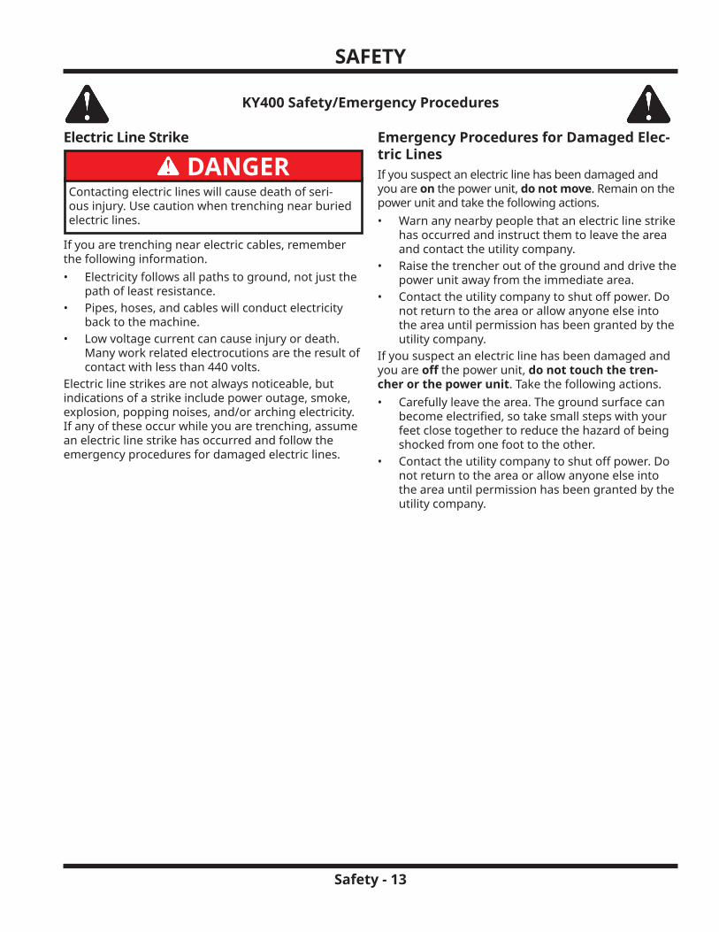
Electric Line Strike
DANGERContacting electric lines will cause death of seri-ous injury. Use caution when trenching near buried electric lines.
If you are trenching near electric cables, remember the following information.• Electricity follows all paths to ground, not just the
path of least resistance.• Pipes, hoses, and cables will conduct electricity
back to the machine.• Low voltage current can cause injury or death.
Many work related electrocutions are the result of contact with less than 440 volts.
Electric line strikes are not always noticeable, but indications of a strike include power outage, smoke, explosion, popping noises, and/or arching electricity. If any of these occur while you are trenching, assume an electric line strike has occurred and follow the emergency procedures for damaged electric lines.
Emergency Procedures for Damaged Elec-tric LinesIf you suspect an electric line has been damaged and you are on the power unit, do not move. Remain on the power unit and take the following actions.• Warn any nearby people that an electric line strike
has occurred and instruct them to leave the area and contact the utility company.
• Raise the trencher out of the ground and drive the power unit away from the immediate area.
• Contact the utility company to shut off power. Do not return to the area or allow anyone else into the area until permission has been granted by the utility company.
If you suspect an electric line has been damaged and you are off the power unit, do not touch the tren-cher or the power unit. Take the following actions.• Carefully leave the area. The ground surface can
become electrified, so take small steps with your feet close together to reduce the hazard of being shocked from one foot to the other.
• Contact the utility company to shut off power. Do not return to the area or allow anyone else into the area until permission has been granted by the utility company.
SAFETY
Safety - 14
KY400 Safety/Emergency Procedures
Gas Line Strike
DANGERDamaged or leaking gas lines can ignite and/or ex-plode, causing death or serious injury and burns. No smoking, flames, or sparks should be allowed in the vicinity of the gas line, to reduce the likelihood of ignition if a gas line is damaged.
Indications of a gas line strike include visual evidence of gas line damage, a hissing sound, and/or the smell of natural gas. If you suspect a gas line strike has occurred, follow the emergency procedures for dam-aged gas lines.
Emergency Procedures for Damaged Gas LinesIf you suspect a gas line has been damaged, take the following actions.• Immediately shut off the power unit engine or
alert the operator to do so. • Warn any nearby people that a gas line strike has
occurred and instruct them to leave the area. Keep everyone away from the area and upwind until the utility company shuts off the gas.
• Remove any ignition sources, if this can be done quickly and safely. Do not start an engine or mo-tor that is already shut off.
• Leave the work area as quickly as possible.• Do not attempt to repair or plug damaged pipes.
Allow the gas to vent into the atmosphere. • If the gas ignites, let it burn. Do not attempt to
put out the flame. Burning gas will not explode.• After leaving the area, call your local emergency
number and the utility company. Do not use your cell phone in the area of the damaged gas line.
• If the damaged gas line is near a street, stop traf-fic from driving near the work area.
• If the damaged gas line is near a building, the oc-cupants should be evacuated. Leave the doors to the building open and do not use light switches, doorbells, or telephones.
• Do not return to the work area until permission has been granted by emergency personnel and the utility company.
SAFETY
Safety - 15
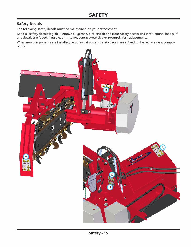
Safety DecalsThe following safety decals must be maintained on your attachment.Keep all safety decals legible. Remove all grease, dirt, and debris from safety decals and instructional labels. If any decals are faded, illegible, or missing, contact your dealer promptly for replacements.When new components are installed, be sure that current safety decals are affixed to the replacement compo-nents.
A
B
A
C
D
SAFETY
Safety - 16
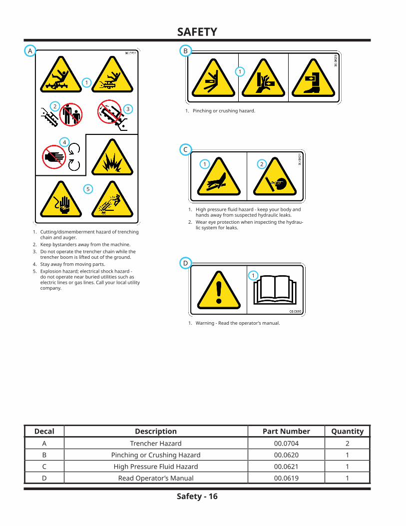
Decal Description Part Number QuantityA Trencher Hazard 00.0704 2B Pinching or Crushing Hazard 00.0620 1C High Pressure Fluid Hazard 00.0621 1D Read Operator’s Manual 00.0619 1
1. Pinching or crushing hazard.
1
B
1. High pressure fluid hazard - keep your body and hands away from suspected hydraulic leaks.
2. Wear eye protection when inspecting the hydrau-lic system for leaks.
1
C
2
1. Warning - Read the operator’s manual.
1
D
A
1. Cutting/dismemberment hazard of trenching chain and auger.
2. Keep bystanders away from the machine.3. Do not operate the trencher chain while the
trencher boom is lifted out of the ground.4. Stay away from moving parts.5. Explosion hazard; electrical shock hazard -
do not operate near buried utilities such as electric lines or gas lines. Call your local utility company.
1
2 3
4
5

Operation - 17
GENERAL OPERATIONDaily Inspection
WARNINGAlways engage the parking brake, shut off the pow-er unit engine, remove the ignition key, and ensure that all moving parts have come to a complete stop before inspecting the components, or attempting any repair or adjustment.
1. Park the machine on a level surface, with the en-gine shut off and all fluids cold.
2. Perform a visual inspection of both the power unit and the attachment. Look for loose or missing hardware, damaged components, or signs of wear.
3. Inspect the hydraulic hoses and the hydraulic fit-tings to ensure tight, leak free connections.
4. Inspect the attachment belt for damage or exces-sive wear. Refer to the Belt Inspection section of this manual.
5. Inspect the trencher chain tension. Refer to the Trencher Chain Tension Inspection section of this manual.
Attaching1. Drive the power unit slowly forward into the hitch
arms of the attachment. Align the lift arms of the power unit with the attachment hitch arms by raising or lowering the front hitch and complete the engagement.
A
B
2. Once completely engaged, move the front hitch latch lever* to the locked position. The latch (A) must lock over the attachment’s hitch arm pin (B).
3. Engage the parking brake* and shut off the engine.
4. Place the attachment belt onto the PTO drive pul-ley on the power unit. Ensure the belt is properly seated in each pulley.
5. Engage the PTO belt tensioner rod.6. Wipe the hose ends clean and connect to the power
unit’s hydraulic quick couplers. If equipped, connect the hoses and the quick couplers so the colored indicators are paired together (red to red, etc.).
Detaching1. Park the power unit on a level surface and engage
the parking brake.*2. Lower the trencher frame to the ground, then low-
er the trencher boom until it contacts the ground.3. Shut off the power unit engine.4. Disengage the PTO belt tensioner rod.5. Remove the attachment belt from the PTO drive
pulley of the power unit.6. Disconnect the hydraulic quick couplers from the
power unit and store the hose ends in the frame holes next to the hydraulic cylinders.
7. Disengage the front hitch locking lever.*8. Restart the power unit and slowly back away from
the attachment. A side to side movement of the steering wheel may aid in disengagement.
Operating ProcedureBefore operation, perform the daily inspection, shift the power unit into low range*, and set the weight transfer select lever* to setting 2 or 3. The trencher foot pad should slide along the ground without dig-ging into the soil.
WARNINGCall before you dig!
If there is any possibility of buried utilities (cables, gas lines, etc.) in the area where you are working, the utilities must be marked prior to working. There should be a Call Before You Dig number listed in the service / information section of your local telephone directory, or you can find the telephone number for your area online.
Make sure any buried utilities have been properly marked. If the trench will cross or run directly adja-cent to an existing utility, carefully dig these areas out by hand until all lines have been located and can then be easily avoided. If possible, have the utility service shut off while working. The utility company can test the lines before returning them to service.The power unit is operated in reverse when digging trenches. Do not drive forward while the trencher boom is engaged in the ground.
*Refer to power unit operator’s manual for operation of power unit controls.
GENERAL OPERATION
Operation - 18
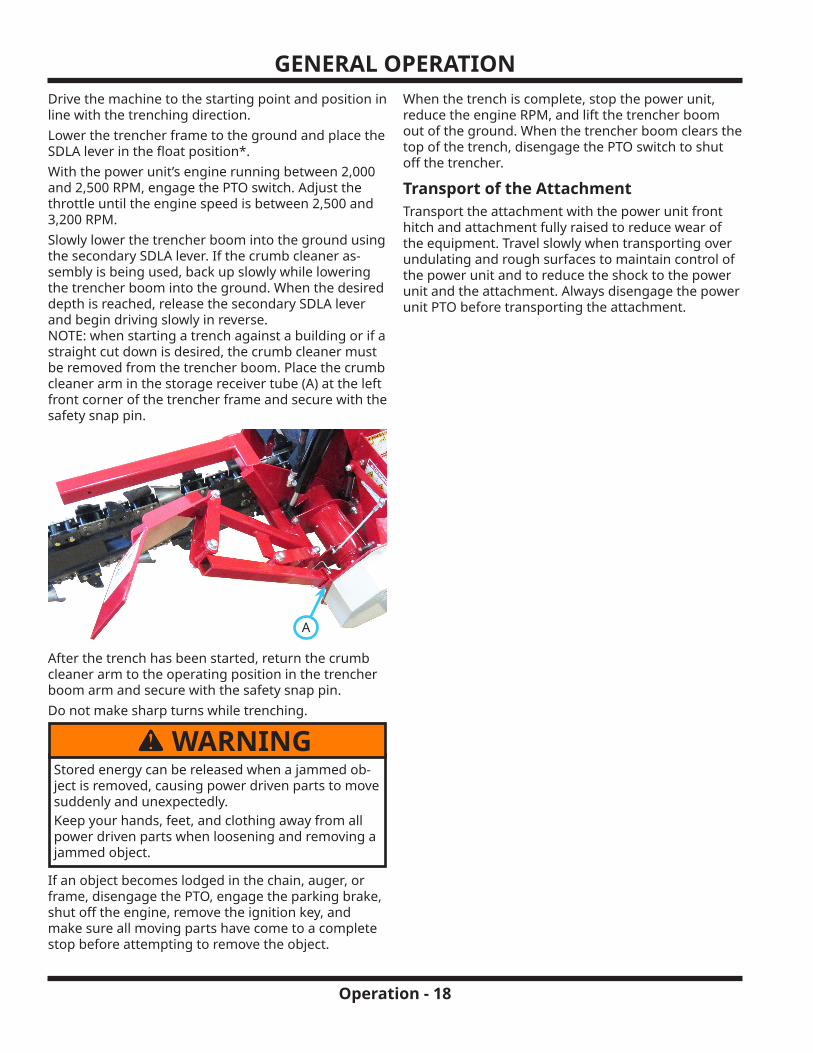
Drive the machine to the starting point and position in line with the trenching direction.Lower the trencher frame to the ground and place the SDLA lever in the float position*.With the power unit’s engine running between 2,000 and 2,500 RPM, engage the PTO switch. Adjust the throttle until the engine speed is between 2,500 and 3,200 RPM.Slowly lower the trencher boom into the ground using the secondary SDLA lever. If the crumb cleaner as-sembly is being used, back up slowly while lowering the trencher boom into the ground. When the desired depth is reached, release the secondary SDLA lever and begin driving slowly in reverse. NOTE: when starting a trench against a building or if a straight cut down is desired, the crumb cleaner must be removed from the trencher boom. Place the crumb cleaner arm in the storage receiver tube (A) at the left front corner of the trencher frame and secure with the safety snap pin.
A
After the trench has been started, return the crumb cleaner arm to the operating position in the trencher boom arm and secure with the safety snap pin.Do not make sharp turns while trenching.
WARNINGStored energy can be released when a jammed ob-ject is removed, causing power driven parts to move suddenly and unexpectedly.Keep your hands, feet, and clothing away from all power driven parts when loosening and removing a jammed object.
If an object becomes lodged in the chain, auger, or frame, disengage the PTO, engage the parking brake, shut off the engine, remove the ignition key, and make sure all moving parts have come to a complete stop before attempting to remove the object.
When the trench is complete, stop the power unit, reduce the engine RPM, and lift the trencher boom out of the ground. When the trencher boom clears the top of the trench, disengage the PTO switch to shut off the trencher.
Transport of the AttachmentTransport the attachment with the power unit front hitch and attachment fully raised to reduce wear of the equipment. Travel slowly when transporting over undulating and rough surfaces to maintain control of the power unit and to reduce the shock to the power unit and the attachment. Always disengage the power unit PTO before transporting the attachment.

Service - 19
SERVICE
WARNINGAlways engage the parking brake, shut off the pow-er unit engine, remove the ignition key, and ensure that all moving parts have come to a complete stop before inspecting the components, or attempting any repair or adjustment.
ATTENTIONIf any component requires replacement, use only original Ventrac replacement parts.
Cleaning and General MaintenanceFor best results, and to maintain the finish of the at-tachment, clean or wash the attachment to remove dirt, mud, and debris.
Belt InspectionInspecting the drive belts of the attachment can prevent sudden belt failure by finding problems before they cause a belt to break.
Glazing Streaked Sidewall
Cracks
Separation
Tensile Break
Typical wear on a drive belt may result in the conditions shown in the diagram. If any of these conditions occur, the drive belt will require replacement.
Attachment Drive Belt Replacement1. Detach the trencher from the power unit.2. Remove the drive pulley shield (A) from the trencher.
3.
A
Remove the old drive belt and install the new drive belt onto the drive pulley.
4. Reinstall the drive pulley shield and torque the mounting bolts to 24 Nm (210 in-lbs).
Drive Chain Tension Inspection5. Lower the trencher and the trencher boom to the
ground.6. Remove the drive chain shield from the left side of
the trencher frame.7. Place a straightedge across the bottom of the
sprockets as shown.
8.
0.5000.1253.5 - 13 mm(1/8 - 1/2 inch)
Lightly press on the chain at the center point between the sprockets to remove the slack. There should be a 3.5 - 13 mm (1/8 - 1/2 inch) gap be-tween the chain and the straightedge.
9. If the chain tension needs adjusted, proceed to the following section for adjustment procedures. If chain tension is correct, reinstall the drive chain shield and torque the bolts to 24 Nm (210 in-lbs).

SERVICE
Service - 20
Drive Chain Tension Adjustment1. Loosen the four gearbox mounting bolts (A).
2.
AB
C
Loosen the jam nut (B) on the gearbox adjustment bolt (C).
3. Tighten or loosen the gearbox adjustment bolt until the correct chain tension is achieved.
4. Tighten the jam nut and torque the four gearbox mounting bolts to 102 Nm (75 ft-lbs).
5. Reinstall the drive chain shield and torque the bolts to 24 Nm (210 in-lbs).
Trencher Chain Tension InspectionCheck the trencher chain tension before each use. With the trencher boom horizontal, measure the distance between the bottom of the boom and the chain at its widest point. The distance should be 32 - 45 mm (1-1/4 - 1-3/4 inches).
32 - 45 mm 32 - 45 mm 1-1/4 - 1-3/4 inches1-1/4 - 1-3/4 inches
Trencher Chain Tension Adjustment1. Loosen the four clamp bolts (A) that secure the
trencher boom to the boom frame arm.
2.
ABC
Loosen the jam nut (B) on the tension adjustment bolt (C).
3. Turn the adjustment bolt clockwise to tighten the chain or counterclockwise to loosen the chain.
ATTENTIONDo not overtighten the trencher chain. Overtighten-ing will cause the chain to stretch and may cause premature chain failure.
4. When the chain tension has been adjusted to the proper range, tighten the jam nut and torque the four clamp bolts to 102 Nm (75 ft-lbs).
Lubrication LocationsLubrication is required at the following locations using a lithium complex NLGI #2 grease. Wipe the grease fittings clean before applying grease to the grease fittings. Refer to the maintenance schedule for service inter-vals and the amount of grease.
SERVICE
Service - 21
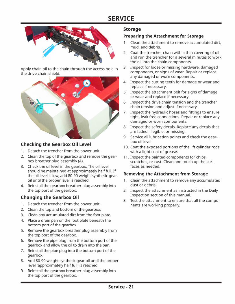
Apply chain oil to the chain through the access hole in the drive chain shield.
A
Checking the Gearbox Oil Level1. Detach the trencher from the power unit.2. Clean the top of the gearbox and remove the gear-
box breather plug assembly (A).3. Check the oil level in the gearbox. The oil level
should be maintained at approximately half full. If the oil level is low, add 80-90 weight synthetic gear oil until the proper level is reached.
4. Reinstall the gearbox breather plug assembly into the top port of the gearbox.
Changing the Gearbox Oil1. Detach the trencher from the power unit.2. Clean the top and bottom of the gearbox.3. Clean any accumulated dirt from the foot plate.4. Place a drain pan on the foot plate beneath the
bottom port of the gearbox.5. Remove the gearbox breather plug assembly from
the top port of the gearbox.6. Remove the pipe plug from the bottom port of the
gearbox and allow the oil to drain into the pan.7. Reinstall the pipe plug into the bottom port of the
gearbox.8. Add 80-90 weight synthetic gear oil until the proper
level (approximately half full) is reached.9. Reinstall the gearbox breather plug assembly into
the top port of the gearbox.
StoragePreparing the Attachment for Storage1. Clean the attachment to remove accumulated dirt,
mud, and debris.2. Coat the trencher chain with a thin covering of oil
and run the trencher for a several minutes to work the oil into the chain components.
3. Inspect for loose or missing hardware, damaged components, or signs of wear. Repair or replace any damaged or worn components.
4. Inspect the cutting teeth for damage or wear and replace if necessary.
5. Inspect the attachment belt for signs of damage or wear and replace if necessary.
6. Inspect the drive chain tension and the trencher chain tension and adjust if necessary.
7. Inspect the hydraulic hoses and fittings to ensure tight, leak free connections. Repair or replace any damaged or worn components.
8. Inspect the safety decals. Replace any decals that are faded, illegible, or missing.
9. Service all lubrication points and check the gear-box oil level.
10. Coat the exposed portions of the lift cylinder rods with a light coat of grease.
11. Inspect the painted components for chips, scratches, or rust. Clean and touch up the sur-faces as needed.
Removing the Attachment from Storage1. Clean the attachment to remove any accumulated
dust or debris.2. Inspect the attachment as instructed in the Daily
Inspection section of this manual.3. Test the attachment to ensure that all the compo-
nents are working properly.

SERVICE
Service - 22
Maintenance Schedule
# of
loca
tions
# of
pum
ps
Dai
ly
At 2
5 ho
urs
At 5
0 ho
urs
At 7
5 ho
urs
At 1
00 h
ours
At 1
25 h
ours
At 1
50 h
ours
At 1
75 h
ours
At 2
00 h
ours
At 2
25 h
ours
At 2
50 h
ours
At 2
75 h
ours
At 3
00 h
ours
At 3
25 h
ours
At 3
50 h
ours
At 3
75 h
ours
At 4
00 h
ours
At 4
25 h
ours
At 4
50 h
ours
At 4
75 h
ours
At 5
00 h
ours
Grease and Lubrication: See Lubrication Section
Boom Frame Pivot Tube 1 ^ ü ü ü ü ü ü ü ü ü ü ü ü ü ü ü ü ü ü ü ü
Lift Cylinder Ends 4 ^ ü ü ü ü ü ü ü ü ü ü ü ü ü ü ü ü ü ü ü ü
Trencher Boom 1 1 ü ü ü ü ü ü ü ü ü ü ü ü ü ü ü ü ü ü ü ü
Check the Gearbox Oil Level ü ü ü ü ü
Change the Gearbox Oil ü ü ü
Inspection
Inspect for Loose, Missing, or Worn Components ü
Inspect the Belts and Pulleys ü
Inspect the Hydraulic Hose and Fittings ü
Inspect the Drive Chain Tension ü ü ü ü ü
Inspect the Trencher Chain Tension ü
Inspect the Trencher Teeth for Damage ü
Inspect the Safety Decals ü
^Grease until fresh grease is visible.
Maintenance Checklist
# of
loca
tions
# of
pum
ps
Dai
ly
At 2
5 ho
urs
At 5
0 ho
urs
At 7
5 ho
urs
At 1
00 h
ours
At 1
25 h
ours
At 1
50 h
ours
At 1
75 h
ours
At 2
00 h
ours
At 2
25 h
ours
At 2
50 h
ours
At 2
75 h
ours
At 3
00 h
ours
At 3
25 h
ours
At 3
50 h
ours
At 3
75 h
ours
At 4
00 h
ours
At 4
25 h
ours
At 4
50 h
ours
At 4
75 h
ours
At 5
00 h
ours
Grease and Lubrication: See Lubrication Section
Boom Frame Pivot Tube 1 ^
Lift Cylinder Ends 4 ^
Trencher Boom 1 1
Check the Gearbox Oil Level
Change the Gearbox OilInspection
Inspect for Loose, Missing, or Worn Components
Inspect the Belts and Pulleys
Inspect the Hydraulic Hose and Fittings
Inspect the Drive Chain Tension
Inspect the Trencher Chain Tension
Inspect the Trencher Teeth for Damage
Inspect the Safety Decals
^Grease until fresh grease is visible.

Specifications - 23
SPECIFICATIONSDimensions
Overall Height . . . . . . . . . . . . . . . . . . . . . . . . . . . . . . . . . . . . . . 75.6 cm (29-3/4 inches)Overall Length . . . . . . . . . . . . . . . . . . . . . . . . . . . . . . . . . . . . . 189 cm (74-1/2 inches)Overall Length with Crumb Cleaner . . . . . . . . . . . . . . . . . . . . . . . . . . . .206 cm (81 inches)Overall Width . . . . . . . . . . . . . . . . . . . . . . . . . . . . . . . . . . . . . . . . .102 cm (40 inches)Weight . . . . . . . . . . . . . . . . . . . . . . . . . . . . . . . . . . . . . . . . . . . 218 kg (480 pounds)Trenching Depth . . . . . . . . . . . . . . . . . . . . . . . . . . . . . . . . . . . . . . .102 cm (40 inches)Trenching Width . . . . . . . . . . . . . . . . . . . . . . . . . . . . . . . . . . . . . .14 cm (5-1/2 inches)Discharge Auger Diameter . . . . . . . . . . . . . . . . . . . . . . . . . . . . . . . . 30.5 cm (12 inches)Material Discharge Reach . . . . . . . . . . . . . . . . . . . . . . . . . . . . . . . . . 35.6 cm (14 inches)
FeaturesTerminator/Cup combo chain with carbide cutting tipsDepth indicator for accurate depth of cutDual push and pull cylinders provide positive boom control for digging, boom lift, and transportAdjustable crumb cleaner
Visit ventrac.com/manuals for the latest version of this operator’s manual.A downloadable parts manual is also available.
View all manuals

SPECIFICATIONS
Specifications - 24
EU Declaration of ConformityVenture Products, Inc., 500 Venture Drive, Orrville, OH 44667, USA, declares that the following unit(s):
Model No. Serial No. Product Description Invoice DescriptionKY400 (39.55455) KY400-AA00000 and Up Ventrac KY400 Trencher Attach-
mentKY, KY400 Trencher
Conform(s) to the following directives:2006/42/EC (Machinery Safety), 2014/30/EU (EMC)
This declaration has been issued under the sole responsibility of the manufacturer.
The object of the declaration is in conformity with relevant Union harmonization legislation.Certified:
Ryan Steiner Engineering Sr. Manager 500 Venture Dr Orrville, OH 44667, USA January 7, 2022
Authorized Representative:Marcel Dutrieux Manager European Product Integrity Toro Europe NV Nijverheidsstraat 5 2260 Oevel Belgium
EU SpecificationsMachine Mass DataModel Machine Mass (kg)*KY400 (39.55455) 218
* In the standard operating configuration with no additional options or kits.
Machine Vibration Data
ModelHand/Arm Vibration (m/s2)* Whole Body Vibration (m/s2)*
Measurement Uncertainty Measurement UncertaintyKY400 (39.55455) 2.5 1 0.7 0.4
* Determined in accordance with EN ISO 5395-1:2013.
Machine Sound Data
ModelSound Pressure (dBA)1 Sound Power (dBA)2
Level Uncertainty Level UncertaintyKY400 (39.55455) 92 2 111 21 A-weighted levels, as measured at the operator position, determined in accordance with EN ISO 5395-1:2013.2 A-weighted levels determined in accordance with EN ISO 5395-1:2013.
Warranty - 25
LIMITED WARRANTY - VENTRAC COMMERCIAL EQUIPMENT
WARRANTY
LIMITED WARRANTY - VENTRAC COMMERCIAL EQUIPMENT
WARRANTY
Venture Products, Inc., (henceforth referred to as V.P.I.) warrants on the terms and conditions herein, that it will repair, replace, or adjust any part manufactured by Venture Products Inc., and found by Venture Products, Inc., to be defective in material and/or workmanship during the applicable warranty term.All Ventrac commercial equipment purchased and registered on or after January 1, 2019 will carry a 2-year commercial warranty. The warranty period begins on the date of the original customer purchase:
Ventrac Commercial Equipment Warranty Term2100 SSV & Attachments 2-year3000 Series Tractors & Attachments 2-year4000 Series Tractors & Attachments 2-year
All Ventrac add-on kits and accessories such as: 3-point hitch, 12V front & rear power outlets, foot pedal, dual wheel kit, etc., will be covered under the above warranty periods provided they are installed by an Authorized Ventrac Dealer. This warranty may be transferred and will carry the remainder of the warranty starting from the original purchase/registration date with the dealership and/or V.P.I. The engine warranty is covered by its respective engine manufacturer. Please refer to the engine manufacturer’s warranty statement that is included in the owner’s manual.For warranty consideration on Ventrac commercial equipment, the equipment, including any defective part, must be returned to an Authorized Ventrac Dealer within the warranty period. The warranty shall extend to the cost to repair or replace (as determined by V.P.I.) the defective part. The expense of pickup and delivery of the equipment, the service call drive time or any transportation expense incurred for the warranty repair is the sole responsibility of the owner and is not covered under warranty by Ventrac and/or V.P.I. Ventrac and V.P.I.’s responsibility in respect to claims is limited to making the required repairs or replacements, and no claim of breach of warranty shall be cause for cancellation or rescission of the contract of sale of any Ventrac equipment. Proof of purchase may be required by the dealer to substantiate any warranty claim. Only warranty work performed and submitted by an Authorized Ventrac Dealer may be eligible for warranty credit.This warranty extends only to Ventrac commercial equipment operated under normal conditions and properly serviced and maintained. The warranty expressly does NOT cover: (a) any defects, damage or deterioration due to normal use, wear and tear, or exposure; (b) normal maintenance services, such as cleaning, lubrication, oil change; (c) replacement of service items, such as oil, lubricants, spark plugs, belts, rubber hoses, bearings or other items subject to normal service replacement; (d) damage or defects arising out of, or relating to abuse, misuse, neglect, alteration, negligence or accident; (e) repair or replacement arising from operation of, or use of the equipment which is not in accordance with the operating instructions as specified in the operator’s manual or other operational instructions provided by V.P.I.; (f) repair or replacement arising as a result of any operation from Ventrac equipment that has been altered or modified so as to, in the determination of V.P.I., adversely affect the operation, performance or durability of the equipment or that has altered, modified or affected the equipment so as to change the intended use of the product; (g) repair or replacement necessitated by the use of parts, accessories or supplies, including gasoline, oil or lubricants, incompatible with the equipment or other than as recommended in the operator’s manual or other operational instructions provided by V.P.I.; (h) repairs or

WARRANTY
Warranty - 26
LIMITED WARRANTY - VENTRAC COMMERCIAL EQUIPMENTreplacements resulting from parts or accessories which have adversely affected the operation, performance or durability of the equipment; or (i) damage or defects due to or arising out of repair of the Ventrac equipment by a person or persons other than an authorized Ventrac service dealer or the installation of parts other than genuine Ventrac parts or Ventrac recommended parts.The sole liability of V.P.I. with respect to this warranty shall be the repair and replacement as set forth herein. V.P.I. shall have no liability for any other cost, loss, or damage. In particular V.P.I shall have no liability or responsibility for: (i) expenses relating to gasoline, oil, or lubricants; (ii) loss, cost or expense relating to transportation or delivery of turf equipment from the location of the owner or the location where used by the owner to or from any Authorized Ventrac Dealer; (iii) travel time, overtime, after hours’ time or other extraordinary repair charges or charge relating to repairs or replacements outside of normal business hours at the place of business of an Authorized Ventrac Dealer; (iv) rental of like or similar replacement equipment during the period of any warranty repair or replacement work; (v) any telephone or telegram charges; (vi) loss or damage to person or property other than that covered by the terms of this warranty; (vii) any claims for lost revenue, lost profit or additional cost or expense incurred as a result of a claim of breach of warranty; or (viii) attorney’s fees.The remedies of the buyer set forth herein are exclusive and are in lieu of all other remedies. The liability of V.P.I., whether in contract, tort, under any warranty, or otherwise, shall not extend beyond its obligation as set forth herein. V.P.I. shall not be liable for cost of removal or installation nor shall V.P.I. be responsible for any direct, indirect, special or consequential damages of any nature. In no event shall V.P.I. be liable for any sum in excess of the price received for the goods for which a liability is claimed.There are no representations or warranties which have been authorized to the buyer of the Ventrac commercial equipment other than set forth in this warranty. Any and all statements or representations made by any seller of this equipment, including those set forth in any sales literature or made orally by any sales representative, are superseded by the terms of this warranty. Any affirmation of fact or promise made by V.P.I. or any of its representatives to the buyer which relates to the goods that are the subject to this warranty shall not be regarded as part of the basis of the bargain and shall not be deemed to create any express warranty that such goods shall conform to the affirmation or promise.No employee, distributor, or representative is authorized to change the foregoing warranties in any way or grant any other warranty on behalf of V.P.I.Some states do not allow limitations on how long an implied warranty lasts or allow the exclusion on limitation of incidental or consequential damages, so the above limitation or exclusion may not apply to you.This warranty gives you specific legal rights, and you may also have other rights which vary from state to state.This warranty applies to all Ventrac commercial equipment sold by Venture Products Inc.


