ICAO EUR DOC 016 INTERNATIONAL CIVIL AVIATION ORGANIZATION EUROPEAN GUIDANCE MATERIAL ON INTEGRITY DEMONSTRATION IN SUPPORT OF CERTIFICATION OF ILS AND MLS SYSTEMS - First Edition - 2004 PREPARED BY THE EUROPEAN AND NORTH ATLANTIC OFFICE OF ICAO SEPTEMBER 2004
Transcript
ICAO EUR DOC 016
INTERNATIONAL CIVIL AVIATION ORGANIZATION
EUROPEAN GUIDANCE MATERIAL ON INTEGRITY DEMONSTRATION IN SUPPORT OF CERTIFICATION
OF ILS AND MLS SYSTEMS
- First Edition -
2004 PREPARED BY THE EUROPEAN AND NORTH ATLANTIC OFFICE OF ICAO SEPTEMBER 2004
First Edition September 2004
THE DESIGNATIONS AND THE PRESENTATION OF MATERIAL IN THIS PUBLICATION DO NOT IMPLY THE EXPRESSION OF ANY OPINION WHATSOEVER ON THE PART OF ICAO CONCERNING THE LEGAL STATUS OF ANY COUNTRY, TERRITORY, CITY OR AREA OF ITS AUTHORITIES, OR CONCERNING THE DELIMITATION OF ITS FRONTIERS OR BOUNDARIES.
7.1 System Safety Assessment Process .................................................................................................... 4 7.2 Specific design approval aspects ........................................................................................................ 6
8. SPECIFIC CONSIDERATIONS ........................................................................................................... 8
APPENDIX A - ILS AND MLS INTEGRITY REQUIREMENTS...............................................A-1
APPENDIX B - SEVERITY CLASSIFICATION OF CONSEQUENCES.................................. B-1
APPENDIX C - SOFTWARE ASSURANCE LEVEL DETERMINATION............................... C-1
APPENDIX D - HARDWARE ASSURANCE LEVEL DETERMINATION.............................D-1
APPENDIX E - INTEGRITY ASSESSMENT EXAMPLES ......................................................... E-1
European guidance material on integrity demonstration in support of certification of ILS and MLS systems 1
First Edition September 2004
1. INTRODUCTION
1.1 ICAO Annex 10 SARPS contain the integrity and continuity requirements for ILS and MLS ground systems. Service providers are required to demonstrate that systems offered for operational service comply with these requirements. This includes an assessment of integrity and an evaluation of continuity of service as part of the initial certification and activities to guarantee continued compliance over the lifecycle of the system. 1.2 The objective of this document is to provide guidance on basic methods that may be applied by States to enable common procedures to be used in the certification of ILS & MLS ground systems in Europe. The intention is that States will be able to use the certification carried out by other co-operating States. This should result in less duplication of work and more effective methods of putting new systems into service thus reducing the effort required by both the certification authority and the manufacturers. 1.3 As an initial step in the development of European Guidance material, the “European Guidance Material on Continuity of Service Evaluation in Support of Certification of ILS & MLS Ground Systems” was developed and published in December 2002 as EUR Doc 012. 1.4 This document focuses on the demonstration that the integrity requirements are being met.
2. SCOPE
2.1 This document provides guidance on: a) Initial demonstration of compliance with the ICAO integrity requirements for ILS & MLS
ground systems.
b) Post certification activities to ensure continued compliance with integrity requirements.
3. DEFINITIONS
3.1 Reliability: The probability that a system will operate within the specified tolerances. 3.2 Integrity: The probability that a system will not radiate incorrect navigation guidance information.
3.3 Continuity of service: The probability that a system will not fail to radiate navigation guidance information during a defined time interval.
3.4 Outage: The failure of a system to radiate navigation guidance.
4. ABBREVIATIONS
CCA Common Cause Analysis ETA Event Tree Analysis EUROCAE European Organisation for Civil Aviation Electronics FHA Functional Hazard Assessment FMEA Failure Mode and Effects Analysis FMECA Failure Modes, Effects and Criticality Analysis FTA Fault Tree Analysis ICAO International Civil Aviation Organisation ILS Instrument Landing System
2 European guidance material on integrity demonstration in support of certification of ILS and MLS systems
First Edition September 2004
MLS Microwave Landing System MTBF Mean Time Between Failures MTBO Mean Time Between Outages PSSA Preliminary System Safety Assessment RTCA Association of aeronautical organisations of USA SARPS Standards And Recommended Practices SSA System Safety Assessment
5. ANNEX 10 - INTEGRITY REQUIREMENTS
5.1 The integrity requirements for ILS are defined Annex 10, Volume I in paragraphs 3.1.3.12 for localizers and 3.1.5.8 for glide-paths. The MLS requirements are specified in paragraphs 3.11.5.2.4 (azimuth) and 3.11.5.3.4 (elevation) respectively (see Appendix A). 5.2 The integrity requirements are expressed as risk “in any one landing”. The intention of the “in any one landing” requirement is that no aircraft should be exposed to an integrity risk higher than 10-9. The risk is the probability to lose integrity over the time interval appropriate to the failure mode. The exposure times used for integrity calculations are dependent on the failure modes being considered. For latent failures the exposure time is determined by the periodicity of maintenance checks (either manual or automatic). For other failure modes where the integrity risk is determined by the probability of a failure event together with the probability of missed detection in a monitor it is necessary to use a suitable exposure time which in this case may be determined by the duration of the operation. In all cases the high level “in any one landing” requirement must be met. 5.3 Figure 1 shows the typical relationship between the integrity risk and time. The risk grows usually exponentially over time. After appropriate checks have taken place (monitor verification action, maintenance checks) the risk is considered to be zero. The interval between the checks should be such that the maximum risk is never greater than the integrity risk requirement. 5.4 A detailed example on the assessment of system integrity is provided in Appendix E.
Figure 1 - Integrity risk and time
European guidance material on integrity demonstration in support of certification of ILS and MLS systems 3
First Edition September 2004
6. CERTIFICATION PROCESS
6.1 Introduction
6.1.1 The certification process includes demonstration of the integrity requirements and evaluation of the continuity of service.
6.1.2 The relationship between integrity and continuity of service is shown in Figure 2.
out of tolerance within tolerance
alarm false alarm
no detectionmisleading
information
(Integrity Risk)
normal operation
Acurracy
failure
detection detection
(Continuity Risk)
Figure 2 - Integrity and Continuity of Service
6.1.3 The low probabilities involved dictate that the integrity demonstration is a process based mainly on analysis during design approval. However, tests and evaluations performed on installed systems are necessary to provide continued assurance that the integrity requirements are being met. Regular verification checks as well as the monitoring of MTBF are important cornerstones in maintaining the required integrity. 6.1.4 Additional guidance on certification considerations may be found in EUROCAE ED-79/ARP 4754 [3]. 6.2 Type approval
6.2.1 Type approval is a series of tests and verifications which are normally only performed once for a particular build state or design of a system. The type approval process includes design approval, operational evaluation and an assessment of the manufacturer’s quality and support procedures to ensure controlled and repeatable production techniques. Certain type approval tests may need to be repeated if the system is subsequently modified. 6.3 Design approval
6.3.1 The manufacturer should provide evidence that the system meets all the non-site-specific requirements for the system. This is normally a combination of practical demonstration results through tests and theoretical analysis to demonstrate compliance with ICAO Annex 10 SARPS. 6.3.2 The manufacturer should provide an analysis showing that the integrity of the system meets the requirement for the intended category of use. As integrity cannot be reasonably verified by field tests, it is essential that this is verified by detailed analysis. 6.3.3 Further guidance on the design approval process is provided in Section 7.
4 European guidance material on integrity demonstration in support of certification of ILS and MLS systems
First Edition September 2004
6.4 Operational evaluation
64.1 For type approval testing, it is normal practice to install the system on a site that is reasonably clear of any obstructions which could affect the radiated signals. 6.4.2 Extensive ground and flight tests should be made to ensure that all parameters of the radiated signal are compliant with ICAO Annex 10 SARPS [1]. Guidance for conducting these tests may be found in ICAO Doc 8071 [2] and guidance for evaluating the results is available in ICAO Doc 8071 and in the Attachments to Annex 10. These type approval tests will normally be more comprehensive than those carried out at commissioning. Such tests should be made at both extremes of the environmental conditions encountered in the State. Long term performance measurements should be made to determine the stability of key parameters in an operational environment. 6.4.3 Operational evaluation is not required to demonstrate compliance with the integrity requirement during type approval. 6.5 Manufacture quality and support procedures
6.5.1 Adequate quality procedures and manufacturing practices should be applied. Evidence of a separate quality organisation, appropriate inspection and test facilities will be required. 6.5.2 Adequate configuration management systems should be in place and for safety critical and safety related areas trace ability to component source should be in place. 6.6 Installation approval
6.6.1 For the certification of individual ground equipment installations additional site-specific factors should be considered: including equipment sitting, ground test procedures and flight verification procedures..
6.7 Post-certification activities
6.7.1 The periodicity of maintenance and flight inspection activities during the operational life of the ground systems should take into account any relevant assumptions made in the integrity analysis.
6.7.2 Changes to hardware or software items require an assessment of their safety impact that may lead to partial or complete re-certification. Procedures should be in place to make sure that changes are brought to the attention of the certification authority.
6.7.3 The MTBF monitoring of the transmitters and monitors is required in order to ensure the validity of the integrity analysis and to identify trends in the equipment which may invalidate the initial failure rate assumptions. If the monitored MTBF is significantly lower than the calculated MTBF the issue should be brought to the attention of the certification authority.
7. DESIGN APPROVAL
7.1 System Safety Assessment Process
7.1.1 Introduction
7.1.1.1 The System Safety Assessment Process provides analytic evidence to demonstrate compliance with the design approval requirements. This process includes specific assessments conducted and updated during system development. It also interacts with the system development supporting processes. The three primary safety assessment steps are Functional Hazard Assessment (FHA), Preliminary System Safety Assessment (PSSA) and System Safety Assessment (SSA).
European guidance material on integrity demonstration in support of certification of ILS and MLS systems 5
First Edition September 2004
7.1.1.2 Additional guidance for conducting the safety assessment process may be found in ARP 4761 [4]. Note: In accordance with the EUROCONTROL Safety Regulatory Requirement: Risk Assessment and
Mitigation in ATM (ESARR4) [5] EUROCONTROL Members States are required to conduct risk assessments when changing the existing ATM environment. The introduction of a new system type e.g. MLS is considered to be such a change. Since ESARR4 requires a total system approach which encapsulates human, procedural and equipment (hardware, software) elements the System Safety Assessment described in this document will form only a part of the total risk assessment necessary in accordance with ESARR4.
7.1.2 Safety assessment tools
7.1.2.1 The safety assessment tools commonly used are:
a) Fault Tree Analysis (FTA) identifies only the failure events that could individually or collectively lead to the occurrence of the undesired top event.
b) Event Tree Analysis (ETA) leading from the top event analyses the different outcomes possible depending on the failure or success of the various mitigation measures.
c) Failure Mode and Effects Analysis (FMEA) provide failure rates to quantify the basic events of the fault tree. A Criticality Analysis (FMECA) reveals areas of the system that are vital to the safety of the product.
d) Common Cause Analysis (CCA) establishes and verifies physical and functional separation and segregation requirements.
7.1.3 Functional hazard assessment
7.1.3.1 The FHA process is a top down approach for identifying the functional failure modes and assessing their effects. 7.1.3.2 The objectives of the FHA are:
a) Identification of all the functions associated with the level under study.
b) Identification and description of failure modes associated with these functions, considering single and multiple failures in normal and degraded environments.
c) Determination of the effects of the failure mode on meeting the integrity and continuity requirements.
d) Classification of the failure mode effects on meeting the integrity and continuity requirements.
e) Identification of the supporting material required to justify the failure mode effect classification.
7.1.3.4 The FHA should consider that a combination of failures should be taken into account and that the approach of allocating just one worst credible severity class for each failure mode is theoretically weak. 7.1.3.5 Consequently, the tools to be used for the FHA are FTA and ETA at a functional level. 7.1.4 Preliminary system safety assessment
6 European guidance material on integrity demonstration in support of certification of ILS and MLS systems
First Edition September 2004
7.1.4.1 The PSSA process is a top down approach that through a systematic examination of the proposed system architecture, determines how failures lead to the functional hazards identified by the FHA. The PSSA addresses all significant Failure Modes identified in the FHA. The PSSA is a method to evaluate proposed architecture and derive system and or item safety requirements. 7.1.4.2 The PSSA should meet the following objectives:
a) To complete the list of system level requirements.
b) To determine whether the architecture, and the planned concept design, can meet the safety requirements and objectives with a reasonable margin.
c) To derive the safety requirements for the design of lower level items (hardware and software), field installation and maintenance tasks.
7.1.4.3 The tools typically used with the PSSA are FTA, ETA and CCA. 7.1.5 System safety assessment
7.1.5.1 The System Safety Assessment is a systematic examination of the system and its architecture to show compliance with safety requirements. The SSA should summarise all significant failure modes and their effects on meeting the integrity and continuity of service requirements. The SSA is the verification that the implemented design meets both the qualitative and quantitative safety objectives and requirements as defined in the FHA and PSSA respectively. 7.1.5.2 The SSA is a bottom up approach for verifying hardware reliability requirements, built-in test requirements, architecture requirements, hardware design assurance levels and software design assurance levels are meeting the safety requirements as delineated in the PSSA process. The lower level of design is again evaluated to determine compliance with derived requirements. 7.1.5.3 Specific guidance on the verification of software and hardware design assurance levels is provided in the sections below. 7.1.5.4 The tools typically used with the SSA are FTA, ETA, FMEA/FMECA and CCA.
7.2 Specific design approval aspects
7.2.1 Hardware/Software partitioning
7.2.1.1 The roles of software and hardware in implementing the functional requirements of a system should be clearly specified and justified. The partitioning of functions between software and hardware should take into account safety criticality, testability, reliability, verification and validation, maintainability, and life cycle cost. 7.2.1.2 The system design process (including hardware and software design processes) will include the safety assessment process. Due to interdependence of the two processes, they will be developed in parallel.
European guidance material on integrity demonstration in support of certification of ILS and MLS systems 7
First Edition September 2004
7.2.1.3 The safety assessment process determines and categorises the failure modes of the system and their effects and consequences. The classification of the severity of consequences scale as defined in more detail in Appendix B is:
a) Severity Class 1 (Most severe) / Accident,
b) Severity Class 2 / Serious incident,
c) Severity Class 3 / Major incident,
d) Severity Class 4 / Significant incident,
e) Severity Class 5 (Least severe) / No immediate effect on safety.
7.2.1.4 The contribution of hardware and software to the failure of equipment function (understand the combination of hardware and software items) will be determined by the Preliminary System Safety Assessment process. The results of this process should be used to establish the appropriate development assurance levels as defined in the EUROCAE/RTCA document ED-109/DO-278 [6] for software design process and ED-80/DO-254 [7] for hardware design process. The hardware/software level of development implies that the level of effort required to show compliance with the safety/integrity requirements varies with the failure condition category. 7.2.2 Software design assurance
7.2.2.1 Software design should follow the guidelines specified in the EUROCAE/RTCA document ED-109/DO-278. This guidance material provides guidelines for the assurance of software contained in non-airborne systems. By assurance level it defines a set of objectives that are recommended to establish the assurance that software has the integrity needed for use in a safety-related application. 7.2.2.2 Software assurance levels are commensurate with safety-related requirements, contribution of software to potential failure conditions and their severity classifications. The software assurance level definitions and additional guidance are provided in Appendix C.
Note 1: The Eurocontrol Safety Regulatory Requirement "Software in ATM Systems" (ESARR6) [10]
established regulatory requirements for the use of software in ATM systems including CNS systems not prescribing any type of supporting means of compliance.
Note 2: In accordance with ESARR6 for software components that cannot be shown to be independent of one
another shall be allocated the software assurance level of the most critical of the dependent components. Software components are independent if they are not rendered inoperative by the same failure condition that causes the hazard.
7.2.3 Hardware design assurance
7.2.3.1 In the absence of a EUROCAE/RTCA document providing guidelines for the assurance of hardware contained in non-airborne ATM/CNS systems, hardware design should follow the guideline specified in the EUROCAE/RTCA document ED-80/DO-254.
Note: This standard was developed to provide guidance on the certification of complex electronic
hardware. Only for these hardware items it is deemed necessary to follow ED-80/DO254. Hardware is considered “simple” if by means of deterministic testing and analyses assurance of correct functional performance under normal operating conditions can be obtained.
8 European guidance material on integrity demonstration in support of certification of ILS and MLS systems
First Edition September 2004
7.2.3.2 In line with the interpretation of ED-12B/DO-178B [8] to define guidelines for the assurance of software not resident within the airframe boundaries which led to the development of ED-109/DO-278, it might be necessary to associate the ATM/CNS hardware levels and the airborne hardware levels. In particular, it might be required to define an additional assurance level to account for certain ATM/CNS systems where the equivalent to assurance level C is too stringent and the equivalent to assurance level D is too lenient. 7.2.3.3 The guidance is applicable, but not limited, to the following hardware items:
a) Line Replaceable Units (LRU)
b) Circuit board assemblies
c) Custom micro-coded components such as Application Specific Integrated Circuits (ASIC) and Programmable Logic Devices (PLD) including any associated macro functions
d) Integrated technology components such as hybrids and multi-chip modules
e) Commercial Off The Shelf (COTS)
7.2.3.4 Hardware design assurance level is based upon the contribution of hardware to potential failure modes as determined by the system safety assessment process. The hardware level definitions and further guidance are provided in Appendix D.
8. SPECIFIC CONSIDERATIONS
8.1 There is no unique way to design a system able to fulfil the ICAO integrity and continuity of service requirement. 8.2 The probability to transmit hazardous misleading information to the users is the product of the probability to generate such information and the probability not to detect it by a monitoring system within a certain time. If the probability to generate such information is demonstrated to be sufficiently remote to be compliant with the integrity requirement, implementation of the monitor system may not be required. Nevertheless, ICAO SARPS require the monitoring of specific parameters through the implementation of specific hardware or software monitors and all known certified ILS or MLS equipment implement these monitors. Monitoring concepts 8.3 In order to reduce the probability of monitor failure, it is common practice to duplicate or triplicate the monitoring system. The way to combine the information from the different sources is design related. There are basically two ways to combine duplicate monitor sources, depending on the combination logic (AND or OR) implementation. AND logic will generate an action if both monitor sources indicate out of tolerance information, while OR logic will generate such action if one of the two sources is indicating out of tolerance information. 8.4 OR logic will provide higher integrity when compared to the AND logic, however this degrades the continuity of service of the system. The proposed logic for the monitoring has to provide the best trade-off between these two fundamental parameters. The manufacturer has to prove through his Safety System Analysis that the proposed architecture fulfils both integrity and continuity of service requirements.
European guidance material on integrity demonstration in support of certification of ILS and MLS systems 9
First Edition September 2004
8.6 Triplicate sources are usually combined using a voting logic (2 of 3). Also in this case a trade-off between integrity and continuity of service performance has to be made and justified by the manufacturer in the system safety analysis. 8.7 In order to guarantee the quality of transmitted information, it may be necessary to check the signal in space at different points in the coverage or in the transmission chain (e.g. at antenna level or in the field). In order to accomplish this, different sensors are implemented within the transmitter (internal monitors), at the transmitter antenna level (integral monitors) or in the near or far field levels (near field or far field monitors). To take into account environmental conditions or different operational status of the equipment (Category of service), some of these monitors may not be implemented or may not have executive powers i.e. their outputs are displayed for information only. Monitor testing 8.8 In order to limit the probability of non-detection by the monitor system, it is common design and operational practice to regularly test the monitor systems of ILS or MLS equipment. The test may be automatic (automatic integrity test). In some designs the equipment elements responsible for switch-over or shutdown are tested either through an automatic integrity test or a manual test (End to End Test). 8.9 The necessity and periodicity of these tests is design dependant and should be validated by the manufacturer through the System Safety Analysis in accordance with the applicable integrity requirements. Redundant equipment testing 8.10 In order to comply with the continuity of service requirements, ground equipment manufacturers generally propose redundant architecture with automatic switch-over to stand-by equipment in the case of failure of the primary transmitter. In some cases, it may be required to guarantee the integrity of the standby transmitter to avoid the switch-over to faulty redundant equipment. There are different ways in which to implement standby equipment monitoring. A periodic switch-over to standby equipment is one such way but monitoring without transmission through the antenna system is another potential solution to a recommended means of redundant equipment testing. Specific design considerations
8.11 The monitoring system is integral to the ILS or MLS equipment design but complete independence (applicable to hardware and software) between the transmission and the monitoring functions is recommended. This is in order to increase the reliability of the monitoring system by avoiding common failure points. Normal practices require independent hardware and software and independent power supplies. When duplicated monitor systems are implemented, independence between the two channels is recommended up to a certain extent to limit these common failure points.
Examples of current design 8.12 Category I ILS/MLS systems are generally based on a single channel (no redundancy in the transmitter or monitoring channels). The equipment is monitored internally and through an integral and/or field monitors. 8.13 Category II ILS/MLS system monitoring is duplicated (due to higher integrity requirements) while the transmitter may still be based on a single channel. 8.14 Category III ILS/MLS systems are fully redundant.
10 European guidance material on integrity demonstration in support of certification of ILS and MLS systems
First Edition September 2004
8.15 For Category III ILS, a far field monitor is generally implemented to monitor the localizer. This monitor is not executive due to its location (threshold area) and potential false alarm due to aircraft on the runway (landing / departing). 8.16 For all MLS Categories, field monitor sensors are generally installed between 30 and 50 m in front of the transmission antennas. All MLS field monitors are executive. 8.17 For ILS/MLS Category II and III systems, an automatic integrity test is implemented. 8.18 If the coverage of the automatic integrity test is not sufficient, a manual End-to-End test is required. The periodicity of these tests is equipment dependant and should be derived from the System Safety Analysis in order to demonstrate safety assurance in compliance with the requirements. 8.19 As an example, a current MLS design implemented an automatic integrity check every 614 ms and a manual End-to-End test every 6 to 8 months. Flight inspection 8.20 Flight checks are not supposed to be used during integrity demonstration. Their objective is to check that environmental conditions are not affecting the signal propagation through out the coverage volume. 8.21 For ILS in particular, it is normal practise during the flight checks to verify the correlation between the ground monitoring and the airborne measurements. Good correlation increases the confidence in ground measurement and may help to optimise the periodicity between periodic flight checks. Discrepancy between ground and airborne measurements may reflect environmental effects and should be taken into account when setting the alarm limits. Normal practices indicate to subtract the difference between ground and airborne measurements to the ICAO alarm limit in order to take into account this discrepancy until good correlation is obtained.
9. REFERENCES
1. ICAO Annex 10 to the Convention on International Civil Aviation, Volume 1.
2. ICAO Doc. 8071 Manual on the Testing of Radio Navigation Aids.
3. EUROCAE ED-79/ARP 4754, Certification Considerations for Highly-Integrated or Complex Aircraft Systems, April 1997.
4. SAE ARP 4761, Guidelines and Methods for Conducting the Safety Assessment Process on Civil Airborne Systems and Equipment, December 1996.
5. ESARR4, EUROCONTROL Safety Regulatory Requirement: Risk Assessment and Mitigation in ATM, Version 1.0, April 2001.
6. EUROCAE ED-109 (RTCA/DO-278), Guidelines for CNS/ATM Systems Software Integrity Assurance, March 2002.
7. EUROCAE ED-80, (RTCA/DO-254), Design Assurance Guidance for Airborne Electronic Hardware, April 2000.
8. EUROCAE ED-12B, (RTCA/DO-178B), Software Considerations in Airborne Systems and Equipment Certification, December 1992.
European guidance material on integrity demonstration in support of certification of ILS and MLS systems 11
First Edition September 2004
9. ACJ 25.1309, JAA Advisory Circular Joint, System Design and Analysis in accordance with JAR25.1309.
10. ESARR6, EUROCONTROL Safety Regulatory Requirement: Software in ATM Systems, Version 1.0, November 2003.
European guidance material on integrity demonstration in support of certification of ILS and MLS systems A–1
First Edition September 2004
APPENDIX A - ILS AND MLS INTEGRITY REQUIREMENTS
ILS INTEGRITY REQUIREMENTS 3.1.3.12 Integrity and continuity of service requirements
3.1.3.12.1 The probability of not radiating false guidance signals shall not be less than 1-0.5×10⁻⁹ in any
one landing for Facility Performance Categories II and III localizers.
3.1.3.12.2 Recommendation.— The probability of not radiating false guidance signals should not be less than 1-1.0×10⁻⁷ in any one landing for Facility Performance Category I localizers. 3.1.5.8 Integrity and continuity of service requirements
3.1.5.8.1 The probability of not radiating false guidance signals shall not be less than 1-0.5×10⁻⁹ in
any one landing for Facility Performance Category II and III glide paths.
3.1.5.8.2 Recommendation.— The probability of not radiating false guidance signals should not be less than 1-1.0×10⁻⁷ in any one landing for Facility Performance Category I glide paths. MLS INTEGRITY REQUIREMENTS 3.11.5.2.4 Integrity and continuity of service requirements for MLS azimuth
3.11.5.2.4.1 The probability of not radiating false guidance signals shall not be less than 1-0.5×10⁻⁹ in any one landing for an MLS azimuth intended to be used for Category II and III operations.
3.11.5.2.4.2 Recommendation.— The probability of not radiating false guidance signals should not be less than 1-1.0×10⁻⁷ in any one landing on MLS azimuth intended to be used for Category I operations.
3.11.5.3.4 Integrity and continuity of service requirements for MLS approach elevation.
3.11.5.3.4.1 The probability of not radiating false guidance signals shall not be less than 1-0.5×10⁻⁹ in any one landing for an MLS approach elevation intended to be used for Category II and III operations. 3.11.5.3.4.2 Recommendation.— The probability of not radiating false guidance signals should not be less than 1-1.0×10⁻⁷ in any one landing on MLS approach elevation intended to be used for Category I operations.
European guidance material on integrity demonstration in support of certification of ILS and MLS systems B–1
First Edition September 2004
APPENDIX B - SEVERITY CLASSIFICATION OF CONSEQUENCES
1. The classification of the severity of consequences scale as defined in Appendix A of ESARR4 is:
a) Severity Class 1 (Most severe) / Accident,
b) Severity Class 2 / Serious Incident,
c) Severity Class 3 / Major incident,
d) Severity Class 4 / Significant Incident,
e) Severity Class 5 (Least severe) / No Immediate Effect on safety.
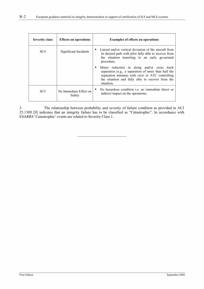
2. The following table provides a framework for assessing the severity of effects of hazards in a specific environment of operations:
Severity class
Effects on operations
Examples of effects on operations
SC1
Accidents ��Lateral and/or vertical deviation of the aircraft from
its desired path leads to a collision with one or more obstacles (ground, buildings, other aircraft) during the precision approach.
��No independent source of recovery mechanism, such as surveillance or ATC and/or flight crew procedures can reasonably be expected to prevent the accident(s).
SC2
Serious Incidents ��Lateral and/or vertical deviation of the aircraft from
its desired path so that abrupt manoeuvre is required to avoid collision with one or more obstacles during the precision approach.
��Large reduction in along and/or cross track separation (e.g., a separation of less than half the separation minima), without crew or ATC fully controlling the situation or able to recover from the situation.
SC3
Major Incidents ��Lateral and/or vertical deviation of the aircraft from
its desired path with pilot fully able to recover from the situation transiting at DH to a missed-approach procedure.
��Large reduction in along and/or cross track separation (e.g., a separation of less than half the separation minima) with crew or ATC controlling the situation and able to recover from the situation.
��Minor reduction in along and/or cross track separation (e.g., a separation of more than half the separation minima) without crew or ATC fully controlling the situation, hence jeopardising the ability to recover from the situation (without the use of collision or terrain avoidance manoeuvres).
B–2 European guidance material on integrity demonstration in support of certification of ILS and MLS systems
First Edition September 2004
Severity class
Effects on operations
Examples of effects on operations
SC4
Significant Incidents ��Lateral and/or vertical deviation of the aircraft from
its desired path with pilot fully able to recover from the situation transiting to an early go-around procedure.
��Minor reduction in along and/or cross track separation (e.g., a separation of more than half the separation minima) with crew or ATC controlling the situation and fully able to recover from the situation.
SC5
No Immediate Effect on
Safety
��No hazardous condition i.e. no immediate direct or indirect impact on the operations.
3. The relationship between probability and severity of failure condition as provided in ACJ 25.1309 [9] indicates that an integrity failure has to be classified as “Catastrophic”. In accordance with ESARR4 ‘Catastrophic’ events are related to Severity Class 1.
European guidance material on integrity demonstration in support of certification of ILS and MLS systems C–1
First Edition September 2004
APPENDIX C - SOFTWARE ASSURANCE LEVEL DETERMINATION
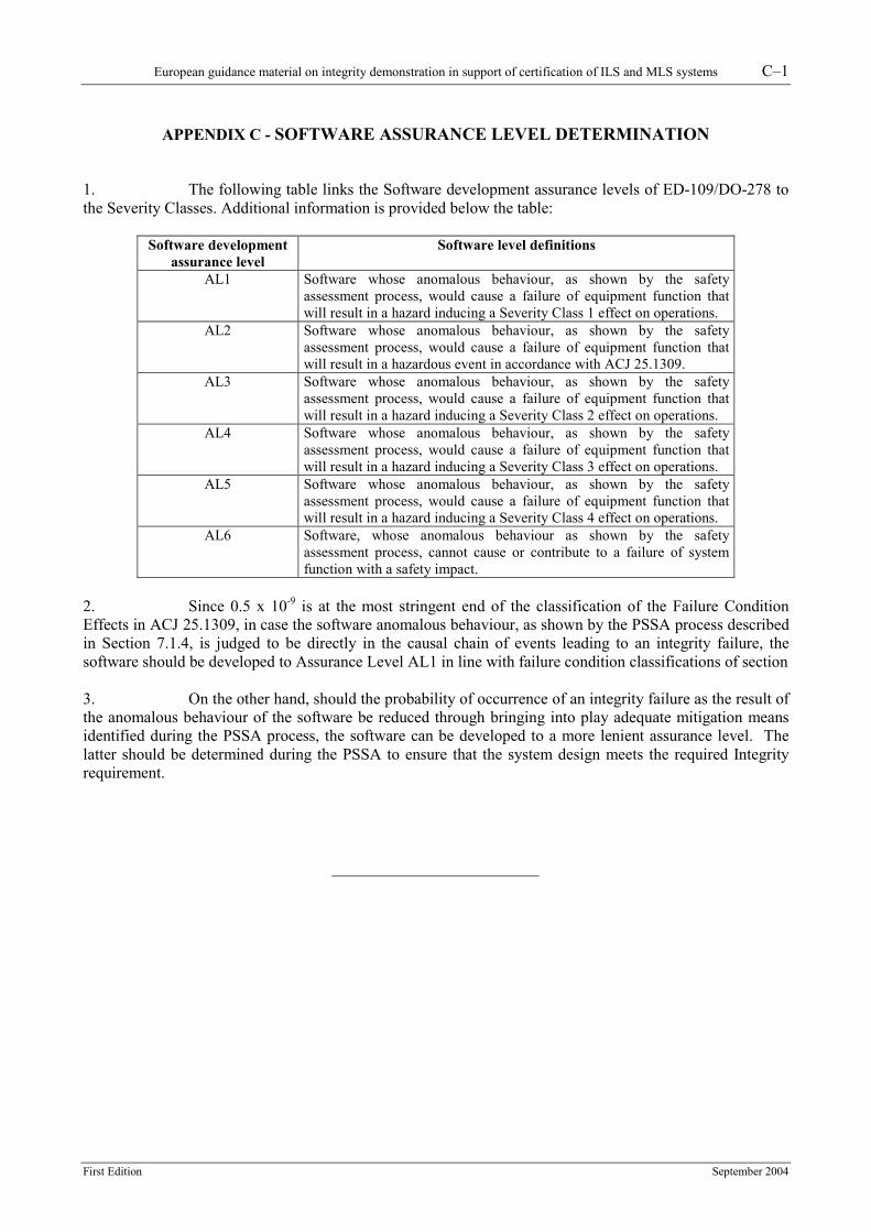
1. The following table links the Software development assurance levels of ED-109/DO-278 to the Severity Classes. Additional information is provided below the table:
Software development assurance level
Software level definitions
AL1 Software whose anomalous behaviour, as shown by the safety assessment process, would cause a failure of equipment function that will result in a hazard inducing a Severity Class 1 effect on operations.
AL2 Software whose anomalous behaviour, as shown by the safety assessment process, would cause a failure of equipment function that will result in a hazardous event in accordance with ACJ 25.1309.
AL3 Software whose anomalous behaviour, as shown by the safety assessment process, would cause a failure of equipment function that will result in a hazard inducing a Severity Class 2 effect on operations.
AL4 Software whose anomalous behaviour, as shown by the safety assessment process, would cause a failure of equipment function that will result in a hazard inducing a Severity Class 3 effect on operations.
AL5 Software whose anomalous behaviour, as shown by the safety assessment process, would cause a failure of equipment function that will result in a hazard inducing a Severity Class 4 effect on operations.
AL6 Software, whose anomalous behaviour as shown by the safety assessment process, cannot cause or contribute to a failure of system function with a safety impact.
2. Since 0.5 x 10⁻⁹ is at the most stringent end of the classification of the Failure Condition Effects in ACJ 25.1309, in case the software anomalous behaviour, as shown by the PSSA process described in Section 7.1.4, is judged to be directly in the causal chain of events leading to an integrity failure, the software should be developed to Assurance Level AL1 in line with failure condition classifications of section 3. On the other hand, should the probability of occurrence of an integrity failure as the result of the anomalous behaviour of the software be reduced through bringing into play adequate mitigation means identified during the PSSA process, the software can be developed to a more lenient assurance level. The latter should be determined during the PSSA to ensure that the system design meets the required Integrity requirement.
European guidance material on integrity demonstration in support of certification of ILS and MLS systems D–1
First Edition September 2004
APPENDIX D - HARDWARE ASSURANCE LEVEL DETERMINATION
1. The following table links the Hardware design assurance levels of ED-80/DO-254 to the severity. Additional information is provided below the table:
Hardware design assurance level
Hardware level definitions
A Hardware functions whose failure or anomalous behaviour, as shown by the System Safety Assessment Process, would cause a failure of system function resulting in a catastrophic failure condition for the aircraft.
B Hardware functions whose failure or anomalous behaviour, as shown by the System Safety Assessment Process, would cause a failure of system function resulting in a hazardous/severe-major failure condition for the aircraft.
C Hardware functions whose failure or anomalous behaviour, as shown by the System Safety Assessment Process, would cause a failure of system function resulting in a major failure condition for the aircraft.
D Hardware functions whose failure or anomalous behaviour, as shown by the System Safety Assessment Process, would cause a failure of system function resulting in a minor failure condition for the aircraft.
E Hardware functions whose failure or anomalous behaviour, as shown by the System Safety Assessment Process, would cause a failure of system with no effect on aircraft operational capability or flight crew workload.
2. By analogy with Appendix C – Software assurance level determination, and in the absence of guidelines for non-airborne hardware, the hardware design should be as follows: 3. In case the hardware functions failure or anomalous behaviour, as shown by the PSSA process described in Section 7.1.4, is judged to be directly in the causal chain of events leading to an integrity failure, the hardware should be developed to Hardware Design Assurance Level A in line with failure condition classifications of section. On the other hand, should the probability of occurrence of an integrity failure as the result of the failure or anomalous behaviour of the hardware functions be reduced through bringing into play adequate mitigation means identified during the PSSA process, the hardware can be developed to a more lenient assurance level. The latter should be determined during the PSSA to ensure that the system design meets the required Integrity.
European guidance material on integrity demonstration in support of certification of ILS and MLS systems E–1
First Edition September 2004
APPENDIX E - INTEGRITY ASSESSMENT EXAMPLES
1. Introduction
1.1 The integrity requirement is set in terms of probability in any one landing for landing system (Navigation System Panel decided to use “in any one operation” rather than “in any one landing” for GNSS). 1.2 The demonstration of compliance is provided by the system manufacturer through the System Safety Analysis. For that, a Risk Case Analysis is necessary in order to determine the failure scenarios leading to an integrity failure. 1.3 Then, the reliability study and a Failure Mode Effect Analysis results have to be used to compute the integrity risk in any one landing. This risk is computed at a given instant and is not constant but varies in time. The different monitoring techniques which are implemented have to be designed such as to limit the maximum risk to a value below the integrity risk requirement. 1.4 The following paragraphs aim to illustrate a typical integrity assessment analysis. However, it has to be noted that software and complex hardware issues have not been considered. 2. Integrity assessment analysis:
a) The system to be analyzed is depicted in Figure 1.
b) It is composed of a single transmitter connected to an antenna system through a Control Unit. This Control Unit enables or disables the transmission depending on information provided by the dual monitor system. These monitors check the signals received by field sensors and compared the detected errors or levels to alert limit thresholds. As soon as one monitor detects out of tolerance transmissions, the Control Unit disables the transmission.
c) The first presented analysis is conducted on this basic system. The results of this analysis are presented in paragraph 2.1.1.
d) A second analysis is conducted taking into account the presence of an automatic integrity check (AIC) which, periodically, checks the ability of the two monitors to detect any monitor failures. The results of this analysis are presented in paragraph 2.2.1.
e) Then, a third analysis is conducted taking into account the additional presence of a so-called End-to-End (ETE) test which, periodically, checks the reliability of the Control Unit. The results of this analysis are presented in paragraph 2.3.1.
E–2 European guidance material on integrity demonstration in support of certification of ILS and MLS systems
First Edition September 2004
Figure 1 – System overview 2.1 Analysis 1
2.1.1 The system is composed of a single transmitter transmitting through an antenna system. The transmitted signal is received by a field monitor sensor which feeds two parallel monitor systems which, in case of failure detection by one of them, is able to shut down the transmission through the Control Unit. The system analysis is supposed to prove that all the subparts of the system are independent, i.e. a failure in one subpart does not lead to a failure in another subpart. This demonstration is fundamental and has to be carefully conducted and reviewed through system analysis. Qualitative analysis 2.1.2 The reliability analysis results are supposed to be the following:
Element Failure per million of hrs
Integrity Failure per million of hrs (note 1)
Transmitter + Antenna system ΛT λT = α 1 ΛT Monitor system ΛM λM = α2 ΛM Field sensor ΛFS λFS = 0 Control Unit ΛCU λCU = α3 ΛCU Note 1: An integrity failure is a failure leading to a hazardous guidance transmission. The failures
which are affecting the continuity or the availability of the service are not taken into account in this integrity analysis. Annex 10 is referencing the ratios between failure and integrity failure as α1, α2 parameters.
Transmitter
Monitor 2
Antenna System
Monitor 1
Field sensor
Control Unit
European guidance material on integrity demonstration in support of certification of ILS and MLS systems E–3
First Edition September 2004
2.1.3 The Risk Case Analysis will determine the scenarios leading to the transmission of hazardous guidance. As long as the transmitted signal is monitored, only a sequence of failures can lead to such transmission. The concerned sequences are extracted from the following table:
Sequence number
Transmitter Monitor 1 Monitor 2 Control unit
Integrity risk
1 OK OK OK OK NO 2 OK OK OK NOK NO 3 OK OK NOK OK NO 4 OK OK NOK NOK NO 5 OK NOK OK OK NO 6 OK NOK OK NOK NO 7 OK NOK NOK OK NO 8 OK NOK NOK NOK NO 9 NOK OK OK OK NO 10 NOK OK OK NOK YES 11 NOK OK NOK OK NO 12 NOK OK NOK NOK YES 13 NOK NOK OK OK NO 14 NOK NOK OK NOK YES 15 NOK NOK NOK OK YES 16 NOK NOK NOK NOK YES
2.1.4 The sequences 10, 12, 14, 15 and 16 lead to a potential hazardous guidance transmission. The failure timing order is important because if the transmitter is failing before the monitoring system, the failure will be detected before the monitor failure but a conservative analysis may not consider the timing aspect. 2.1.5 From this table and reliability figures, the integrity risk may be computed for each scenario. Sequence 10 2.1.6 For this scenario, both the transmitter and the Control Unit are faulty and therefore the hazardous signal is still transmitted despite of out-of-tolerance detection by the monitors. The probability of transmitter integrity failure during a given time t is λT t. The probability of Control Unit integrity failure during a given time t is λCU t. Assuming independence between these two subparts (no common cause failure), the probability of dual integrity failure during t is: P10 = λT t λCU t = λT λCU t² Sequence 12 P12 = λT t λM t λCU t = λT λCU λM t3 Sequence 14 P14 = λT. t λM t λCU t = λT λCU λM t3 Sequence 15 P15 = λT t λM t λM t = λT λ²M t3
E–4 European guidance material on integrity demonstration in support of certification of ILS and MLS systems
First Edition September 2004
Sequence 16 P16 = λT t λM t λM t λCU t = λT λ²M λCU t4
and the total integrity risk may be computed as the sum of the sequence individual risks PTotal1 = P10 + P12 + P14 + P15 + P16 Quantitative analysis 2.1.7 Assuming that the system is composed of hardware exclusively, the reliability may be assessed based on reliability model as presented in MIL-Handbook documentation. To illustrate the previous case quantitatively, the following figures are proposed:
Element Failure per million of hrs Integrity failure per million of hrs (note 1)
Transmitter + Antenna system ΛT λT = 0.1 Monitor system ΛM λM = 10 Field sensor ΛFS λFS = 0 Control Unit ΛCU λCU = 0.01
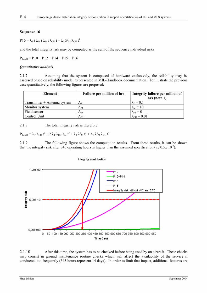
2.1.8 The total integrity risk is therefore: PTotal1 = λT λCU t² + 2 λT λCU λM t3 + λT λ²M t3 + λT λ²M λCU t4 2.1.9 The following figure shows the computation results. From these results, it can be shown that the integrity risk after 345 operating hours is higher than the assumed specification (i.e.0.5x 10-9).
2.1.10 After this time, the system has to be checked before being used by an aircraft. These checks may consist in ground maintenance routine checks which will affect the availability of the service if conducted too frequently (345 hours represent 14 days). In order to limit that impact, additional features are
European guidance material on integrity demonstration in support of certification of ILS and MLS systems E–5
First Edition September 2004
introduced into the system. The second analysis is presenting one potential feature knows as Automatic Integrity Check. 2.2 Analysis 2
2.2.1 An Automatic Integrity Check (AIC) feature is now added to the previous system. This AIC is checking automatically the two monitors at periodic instant. Just after such check, the monitors are supposed to be fault free. The AIC circuitry may also fail and is therefore added in the reliability analysis. Qualitative analysis 2.2.2 The reliability analysis results are supposed to be the following:
Element Failure per million of hrs
Integrity Failure per million of hrs (note 1)
Transmitter + Antenna system ΛT λT Monitor system ΛM λM Field sensor ΛFS λFS = 0 Control Unit ΛCU λCU AIC ΛAIC λAIC
Note 1: An integrity failure is a failure leading to a hazardous guidance transmission. The failures
which are affecting the continuity or the availability of the service are not taken into account in this integrity analysis.
2.2.3 The risk case analysis will determine the scenarios leading to the transmission of hazardous guidance. As long as the transmitted signal is monitored, only a sequence of failures can lead to such transmission. The concerned sequences are extracted from the following table:
Sequence number
Transmitter Monitor 1
Monitor 2
Control Unit
AIC Integrity risk
17 NOK OK OK OK OK NO 18 NOK OK OK OK NOK NO 19 NOK OK OK NOK OK YES 20 NOK OK OK NOK NOK YES 21 NOK OK NOK OK OK NO 22 NOK OK NOK OK NOK NO 23 NOK OK NOK NOK OK YES 24 NOK OK NOK NOK NOK YES 25 NOK NOK OK OK OK NO 26 NOK NOK OK OK NOK NO 27 NOK NOK OK NOK OK YES 28 NOK NOK OK NOK NOK YES 29 NOK NOK NOK OK OK YES between
2 AIC 30 NOK NOK NOK OK NOK YES 31 NOK NOK NOK NOK OK YES 32 NOK NOK NOK NOK NOK YES
2.2.4 The 16 first sequences without Transmitter failures are not depicted in this table as they do not lead to an integrity risk. 2.2.5 The sequences 19, 20, 23, 24, 27, 28, 30, 31 and 32 lead to a potential hazardous guidance transmission. The sequence 29 is hazardous between 2 AIC tests (TAIC). The failure timing order is one
E–6 European guidance material on integrity demonstration in support of certification of ILS and MLS systems
First Edition September 2004
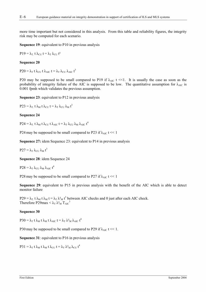
more time important but not considered in this analysis. From this table and reliability figures, the integrity risk may be computed for each scenario. Sequence 19: equivalent to P10 in previous analysis P19 = λT. t λCU t = λT λCU t² Sequence 20 P20 = λT t λCU t λAIC t = λT λCU λAIC t3
P20 may be supposed to be small compared to P19 if λAIC t <<1. It is usually the case as soon as the probability of integrity failure of the AIC is supposed to be low. The quantitative assumption for λAIC is 0.001 fpmh which validates the previous assumption. Sequence 23: equivalent to P12 in previous analysis P23 = λT. t λM t λCU t = λT λCU λM t3 Sequence 24 P24 = λT. t λM t λCU t λAIC t = λT λCU λM λAIC t4
P24 may be supposed to be small compared to P23 if λAIC t << 1 Sequence 27: idem Sequence 23: equivalent to P14 in previous analysis P27 = λT λCU λM t3 Sequence 28: idem Sequence 24 P28 = λT λCU λM λAIC t4
P28 may be supposed to be small compared to P27 if λAIC t << 1 Sequence 29: equivalent to P15 in previous analysis with the benefit of the AIC which is able to detect monitor failure P29 = λT. t λM t λM t = λT λ²M t3 between AIC checks and 0 just after each AIC check. Therefore P29max < λT λ²M TAIC
3
Sequence 30 P30 = λT t λM t λM t λAIC t = λT λ²M λAIC t4
P30 may be supposed to be small compared to P29 if λAIC t << 1. Sequence 31: equivalent to P16 in previous analysis P31 = λT t λM t λM t λCU t = λT λ²M λCU t4
European guidance material on integrity demonstration in support of certification of ILS and MLS systems E–7
First Edition September 2004
Sequence 32 P32 = λT t λM t λM t λCU t λAIC t = λT λ²M λCU λAIC t5 P32 may be supposed to be small compared to P31 if λAIC t << 1
The total integrity risk may be computed as the sum of the sequence individual risks. If the small terms are neglected, PTotal2 < P19 + 2 P23 + P29max + P31 = P10 + 2. P12 + P15 + P16 - (P15 - P29 max) PTotal2 < PTotal1- (P15-P29max) P15-P29max represents the gain provided by the AIC. Quantitative analysis 2.2.6 Assuming the following reliability figures:
Element Failure per million of hrs
Integrity failure per million of hrs (note 1)
Transmitter + Antenna system ΛT λT = 0.1 Monitor system ΛM λM = 10 Field sensor ΛFS λFS = 0 Control Unit ΛCU λCU = 0.01 AIC ΛAIC λAIC =0.001 TAIC = 5 h
2.2.7 The total integrity risk is presented on the following figure.
E–8 European guidance material on integrity demonstration in support of certification of ILS and MLS systems
First Edition September 2004
2.2.8 The figure shows the benefit introduced by the AIC. The time between ground periodic checks is doubled (one month). The addition of the AIC in the system allows the withdrawal of some contributions in the Integrity risk formulation. The non-tested element (the Control Unit) is responsible for the remaining integrity risk. The testing of the remaining system subpart may bring an additional benefit as presented in 2.3.1. 2.3 Analysis 3 2.3.1 An End-to-End Check (ETE) feature is now added to the previous system. This ETE is checking the Control Unit at periodic instant. Just after such check, the Control Unit is supposed to be fault free. The ETE may also fail and is therefore added in the reliability analysis. Qualitative analysis 2.3.2 The reliability analysis results are supposed to be the following:
Element Failure per million of hrs
Integrity Failure per million of hrs (note 1)
Transmitter + Antenna system ΛT λT Monitor system ΛM λM Field sensor ΛFS λFS = 0 Control Unit ΛCU λCU AIC ΛAIC λAIC ETE ΛETE λETE
Note 1: An integrity failure is a failure leading to a hazardous guidance transmission. The failures
which are affecting the continuity or the availability of the service are not taken into account in this integrity analysis.
2.3.3 The Risk Case Analysis will determine the scenarios leading to the transmission of hazardous guidance. As long as the transmitted signal is monitored, only a sequence of failures can lead to such transmission. 2.3.4 The concerned sequences are extracted from the following table:
Sequence number
Transmitter Monitor 1 Monitor 2
Control Unit
AIC ETE Integrity risk
33 NOK OK OK OK OK OK NO 34 NOK OK OK OK OK NOK NO 35 NOK OK OK OK NOK OK NO 36 NOK OK OK OK NOK NOK NO 37 NOK OK OK NOK OK OK YES between
2 ETE 38 NOK OK OK NOK OK NOK YES 39 NOK OK OK NOK NOK OK YES between
2 ETE 40 NOK OK OK NOK NOK NOK YES 41 NOK OK NOK OK OK OK NO 42 NOK OK NOK OK OK NOK NO 43 NOK OK NOK OK NOK OK NO 44 NOK OK NOK OK NOK NOK NO 45 NOK OK NOK NOK OK OK YES between
2 ETE 46 NOK OK NOK NOK OK NOK YES
European guidance material on integrity demonstration in support of certification of ILS and MLS systems E–9
First Edition September 2004
Sequence number
Transmitter Monitor 1 Monitor 2
Control Unit
AIC ETE Integrity risk
47 NOK OK NOK NOK NOK OK YES between 2 ETE
48 NOK OK NOK NOK NOK NOK YES 49 NOK NOK OK OK OK OK NO 50 NOK NOK OK OK OK NOK NO 51 NOK NOK OK OK NOK OK NO 52 NOK NOK OK OK NOK NOK NO 53 NOK NOK OK NOK OK OK YES between
2 ETE 54 NOK NOK OK NOK OK NOK YES 55 NOK NOK OK NOK NOK OK YES between
2 ETE 56 NOK NOK OK NOK NOK NOK YES 57 NOK NOK NOK OK OK OK YES between
2 AIC 58 NOK NOK NOK OK OK NOK YES between
2 AIC 59 NOK NOK NOK OK NOK OK YES 60 NOK NOK NOK OK NOK NOK YES 61 NOK NOK NOK NOK OK OK YES between
2 ETE 62 NOK NOK NOK NOK OK NOK YES 63 NOK NOK NOK NOK NOK OK YES between
2 ETE 64 NOK NOK NOK NOK NOK NOK YES
2.3.5 The 32 first sequences without transmitter failures are not depicted in the previous table as they do not lead to an integrity risk. 2.3.6 A pair of integrity risk scenarios may be associated to a single scenario from the previous analysis (37, 38 with 19; 39, 40 with 20; 45, 46 with 23; 47, 48 with 24; 53, 54 with 27; 55, 56 with 28; 57, 58 with 29; 59, 60 with 30; 61, 62 with 31; 63 and 64 with 32). 2.3.7 Each pair is composed of two scenarios which differ by the failure of the ETE feature. In a first approximation, it may be assumed that the second scenario of each pair has a lower probability and may be neglected. 2.3.8 The ETE benefit consists in assuming that after each ETE any failure of the Control Unit will be detected reducing the integrity risk to zero. 2.3.9 The total integrity risk of this third system is therefore: Ptotal3 = P37 + P39 + P45 + P47 + P53 + P55 + P57 + P59 + P61 + P63 Except for P57 and P59 which are similar to P29 and P30 of the previous analysis, all other probabilities are lower than the previous case because of the ETE. 2.3.10 The gain is linked to the fact that the risk probability is reset at each ETE occurrence and is therefore limited to a maximum value that is reached just before the ETE test. This maximum value is therefore directly linked to the time between ETE tests.
E–10 European guidance material on integrity demonstration in support of certification of ILS and MLS systems
First Edition September 2004
2.3.11 For example P37 is associated to P19 P19 = λT t λCU t = λT λCU t² > λT λCU TETE² Therefore P37 < λT λCU TETE² 2.3.12 For the quantitative analysis, P37 is supposed to be equal to zero at each ETE discrete instant and to increase between the ETE instant following λT λCU t² rate. 2.3.13 Same logic is applied for the following probabilities. P39 < λT λCU λAIC TETE
3
P45 < λT λCU λM TETE 3
P47 < λT λCU λM λAIC TETE
4
P53 < λT λCU λM TETE 3
P55 < λT λCU λM λAIC TETE
4
P57 < λT λ²M TAIC3
P59 = λT. t λM t λM t λAIC t = λT λ²M λAIC t4
P61 < λT λ²M λCU TETE 4
P63 < λT λ²M λCU λAIC TETE
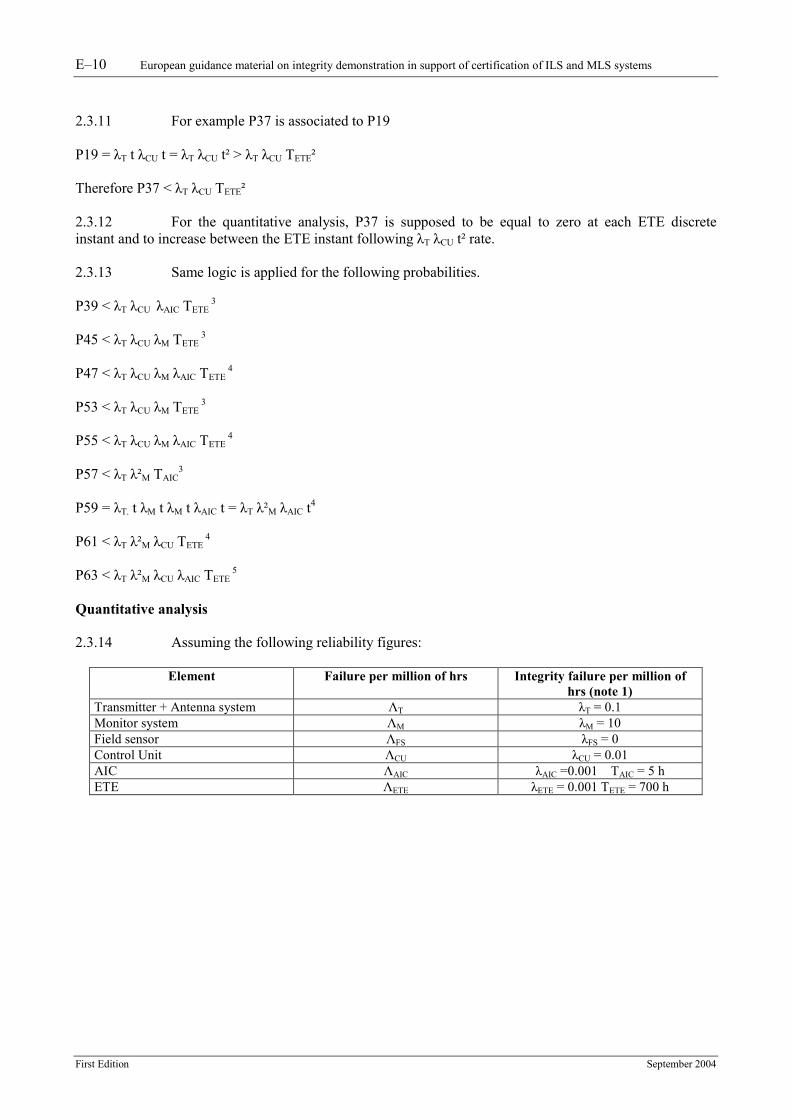
5 Quantitative analysis 2.3.14 Assuming the following reliability figures:
Element Failure per million of hrs Integrity failure per million of hrs (note 1)
Transmitter + Antenna system ΛT λT = 0.1 Monitor system ΛM λM = 10 Field sensor ΛFS λFS = 0 Control Unit ΛCU λCU = 0.01 AIC ΛAIC λAIC =0.001 TAIC = 5 h ETE ΛETE λETE = 0.001 TETE = 700 h
European guidance material on integrity demonstration in support of certification of ILS and MLS systems E–11
First Edition September 2004
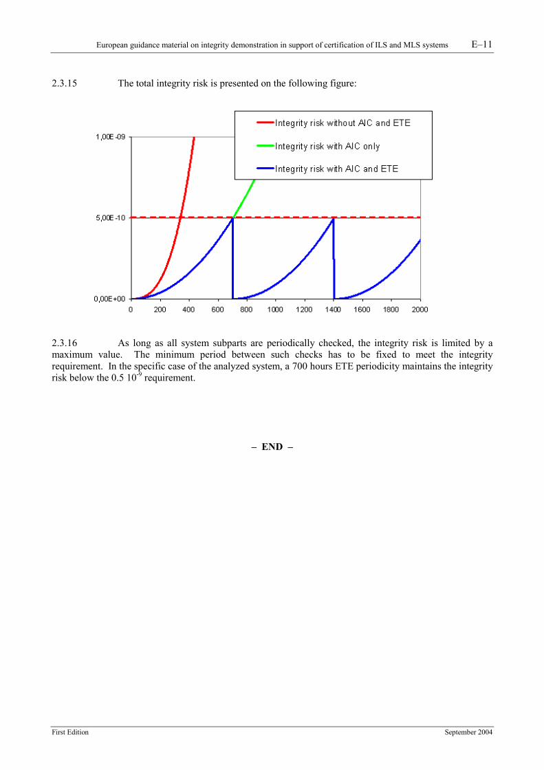
2.3.15 The total integrity risk is presented on the following figure:
2.3.16 As long as all system subparts are periodically checked, the integrity risk is limited by a maximum value. The minimum period between such checks has to be fixed to meet the integrity requirement. In the specific case of the analyzed system, a 700 hours ETE periodicity maintains the integrity risk below the 0.5 10-9 requirement.