ETA-Danmark A/S Kollegievej 6 DK-2920 Charlottenlund Tel. +45 72 24 59 00 Fax +45 72 24 59 04 Internet www.etadanmark.dk MEMBER OF EOTA Authorised and notified according to Article 10 of the Council Directive 89/106/EEC of 21 December 1988 on the approximation of laws, regulations and administrative provisions of Member States relating to construction products European Technical Approval ETA-10/0153 This ETA replaces the previous ETA with the same number and validity from 2011-01-14 to 2015-06-10 Trade name: Sima stanchion holders type B150, B100, B2-100, B2-200, S350, S450, BH-160, UHB2, type U (40, 70 and 90 mm) and type BH-165 Holder of approval: Sima Industri ApS Industrivej Nord 40 DK-7490 Aulum Tel. +45 97 47 26 11 Fax +45 97 47 37 11 Internet www.simaindustri.dk Generic type and use of con- struction product: Three-dimensional nailing plate (timber to concrete post base) Valid from: to: 2011-05-26 2015-06-10 Manufacturing plant: Sima Industri ApS Industrivej Nord 40 DK-7490 Aulum This European Technical Approval contains: 25 pages including 2 annexes which form an integral part of the document
Authorised and notified according to Article 10 of the Council Directive 89/106/EEC of 21 December 1988 on the approximation of laws, regulations and administrative provisions of Member States relating to construction products
European Technical Approval ETA-10/0153
This ETA replaces the previous ETA with the same number and validity from 2011-01-14 to 2015-06-10 Trade name:
Sima stanchion holders type B150, B100, B2-100, B2-200, S350, S450, BH-160, UHB2, type U (40, 70 and 90 mm) and type BH-165
Holder of approval: Sima Industri ApS Industrivej Nord 40 DK-7490 Aulum Tel. +45 97 47 26 11 Fax +45 97 47 37 11 Internet www.simaindustri.dk
Generic type and use of con-struction product:
Three-dimensional nailing plate (timber to concrete post base)
Valid from: to:
2011-05-26 2015-06-10
Manufacturing plant: Sima Industri ApS Industrivej Nord 40 DK-7490 Aulum
This European Technical Approval contains:
25 pages including 2 annexes which form an integral part of the document
Page 2 of 25 of European Technical Approval no. ETA-10/0153
I LEGAL BASIS AND GENERAL CONDITIONS
1 This European Technical Approval is issued by
ETA-Danmark A/S in accordance with: - Council Directive 89/106/EEC of 21 December
1988 on the approximation of laws, regulations and administrative provisions of Member States relating to construction products1), as amended by Council Directive 93/68/EEC of 22 July 19932).
- Bekendtgørelse 559 af 27-06-1994 (afløser
bekendtgørelse 480 af 25-06-1991) om ikrafttræ-den af EF direktiv af 21. december 1988 om indbyrdes tilnærmelse af medlemsstaternes love og administrative bestemmelser om byggevarer.
- Common Procedural Rules for Requesting,
Preparing and the Granting of European Techni-cal Approvals set out in the Annex to Commis-sion Decision 94/23/EC3).
- EOTA Guideline ETAG 015 Three-dimensional
nailing plates, September 2002 edition. 2 ETA-Danmark A/S is authorized to check whet-
her the provisions of this European Technical Approval are met. Checking may take place in the manufacturing plant. Nevertheless, the responsi-bility for the conformity of the products to the European Technical Approval and for their fitness for the intended use remains with the holder of the European Technical Approval.
3 This European Technical Approval is not to be
transferred to manufacturers or agents of manu-facturers other than those indicated on page 1, or manufacturing plants other than those indicated on page 1 of this European Technical Approval.
4 This European Technical Approval may be
withdrawn by ETA-Danmark A/S pursuant to Article 5(1) of Council Directive89/106/EEC.
5 Reproduction of this European Technical Approval including transmission by electronic means shall be in full. However, partial reproduction can be made with the written consent of ETA-Danmark A/S. In this case partial reproduction has to be designated as such. Texts and drawings of advertising brochures shall not contradict or misuse the European Technical Approval.
6 This European Technical Approval is issued by
ETA-Danmark A/S in Danish. This version corresponds fully to the version circula-
ted within EOTA. Translations into other languages have to be designated as such.
1) Official Journal of the European Communities No L40, 11 Feb 1989, p 12. 2) Official Journal of the European Communities No L220, 30 Aug 1993, p 1. 3) Official Journal of the European Communities No L 17, 20 Jan 1994, p 34.
Page 3 of 25 of European Technical Approval no. ETA-10/0153
II SPECIAL CONDITIONS OF THE EUROPEAN TECHNICAL APPROVAL
1 Definition of product and intended use Definition of the product Sima stanchion holders type B150, B100, B2-100, B2-200, S350, S450, BH-160, UHB2, type U (40, 70 and 90 mm) and type BH-165 are welded steel connectors (post bases). The upper part e.g. a plate or a U-shaped plate is fastened to the timber member with nails, screws, bolts or dowels. The lower part of the post base is either a bar, a threaded rod, a tube or a plate for embedment into the support of concrete or a steel plate to be fastened by anchor bolts to the support of concrete. The post bases are made from pre-galvanized steel Grade S 235 JRG2 according to EN 10025 with a corrosion protection of hot dipped galvanized according to EN ISO 1461 with a zinc coating thickness of approximately 55 µm. In addition, the stanchion holders can be delivered with electroplated zinc corrosion protection made from 12µm Fe/Zn 12c. Steel quality, dimensions of the post bases and hole positions are shown in Annex A. Intended use The intended use of the post bases is to support timber structures or wood-based structural members to their support, where requirements for mechanical resistance and stability and safety in use in the sense of the Essential Requirements 1 and 4 of Council Directive 89/106/EEC shall be fulfilled. Each connection shall be made with one post base. The static and kinematic behaviour of the timber members or the supports shall be as described in Annex B. The wood members can be of solid timber, glued laminated timber and similar glued members, or wood-based structural members with a characteristic density from 290 kg/m3 to 420 kg/m3. Depending on the fastening in the wood there are different demands for the wood material. For nailing in the side of the wood members the requirement to the material of the wood members can be fulfilled by using the following materials:
• Solid timber classified to C18-C40 according to EN 338 / EN 14081
• Glued members of timber classified to C18-C40 according to EN 338 / EN 14081 when structural adhesives are used.
• Glued laminated timber classified to GL24c or better according to EN 1194 / EN 14080.
Annex B states the load-carrying capacities of the post base connections for a characteristic density of the timber for at least 320 kg/m3. The load-carrying capacity of the connections for a lower characteristic density should be determined under the assumption that the load-carrying capacity is proportional to the density. The concrete strength class is assumed to be C15 unless otherwise indicated in Annex B. The design of the connections shall be in accordance with Eurocode 5 or a similar national Timber code. The post bases are intended for use for connections subjected to static or quasi static loading. The post bases with a electroplated zinc coating 12µm Fe/Zn 12c are intended for use in service class 1 and 2 according to EN 1995 (Eurocode 5). The post bases which are hot dipped galvanized according to EN ISO 1461 with a zinc coating thickness of approximately 55 µm are intended for use in service class 1, 2 and 3 according to EN 1995 (Eurocode 5). It is assumed that the force acting on the post base is an upward or downward force F1 acting in the centre of the post base Assumed working life The assumed intended working life of the Angle Brackets for the intended use is 50 years, provided that they are subject to appropriate use and maintenance. The information on the working life should not be regarded as a guarantee provided by the manufacturer or ETA-Danmark A/S. An “assumed intended working life” means that it is expected that, when this working life has elapsed, the real working life may be, in normal use conditions, considerably longer without major degradation affecting the essential requirements.
Page 4 of 25 of European Technical Approval no. ETA-10/0153
2 Characteristics of product and assessment
ETAG para.
Characteristic
Assessment of characteristic
2.1 Mechanical resistance and stability*)
6.1.1
Characteristic load-carrying capacity
See Annex B
6.1.2
Stiffness
No performance determined
6.1.3
Ductility in cyclic testing
No performance determined
2.2 Safety in case of fire
6.2.1
Reaction to fire
The post bases are made from steel classified as Euroclass A1 in accordance with EN 13501-1 and EC decision 96/603/EC, amended by EC Decision 2000/605/EC
2.3 Hygiene, health and the environment
6.3.1
Influence on air quality
No dangerous materials **)
2.4 Safety in use
Not relevant
2.5 Protection against noise
Not relevant
2.6 Energy economy and heat retention
Not relevant
2.7 Related aspects of serviceability
6.7.1
Durability
The post bases have been assessed as having satisfactory durability and serviceability when used in timber structures using the timber species described in DS 413 and subject to the dry internal conditions defined by service class 1, 2 and 3
6.7.2
Serviceability
6.7.3
Identification
See Annex A
*) See page 5 of this ETA **) In accordance with http://europa.eu.int-/comm/enterprise/construction/internal/dangsub/dangmain.htm In addition to the specific clauses relating to dangerous substances contained in this European Technical Approval, there may be other requirements applicable to the products falling within its scope (e.g. transposed European legislation and national laws, regulations and administrative provisions). In order to meet the provisions of the EU Construction Products Directive, these requirements need also to be complied with, when and where they apply.
Page 5 of 25 of European Technical Approval no. ETA-10/0153
Safety principles and partial factors The characteristic load-carrying capacities have been calculated without considering different ratios between the partial factors for timber connections and steel cross sections. Therefore, in the end use calculation based on this ETA, this shall be considered. The values in annex B have been determined by multiplying the calculated resistance of the connection by kmod to consider load duration and service classes in accordance with EC 5. Additionally, the capacities indicated for the upward force F1 takes into account the national partial safety factor γM. 2.1 Mechanical resistance and stability See annex B for characteristic load-carrying capacity in the direction F1.. The characteristic capacities of the post bases are determined by calculation as described in the EOTA Guideline 015 clause 5.1.2. They should be used for designs in accordance with Eurocode 5 or a similar national Timber Code. Connector nails in accordance to national approval The load bearing capacities of the post bases has been determined based on the use of NKT connector nails 4,0 x 40 mm and 4,0 × 60 mm in accordance with the Danish national approval for the nails. The characteristic withdrawal capacity of the nails has been determined by testing in accordance with EN 1382: Timber structures - Test methods - Withdrawal capacity of timber fasteners: For electroplated zinc covered nails No performance has been determined in relation to ductility of a joint under cyclic testing. The contribution to the performance of structures in seismic zones, therefore, has not been assessed. No performance has been determined in relation to the joint’s stiffness properties - to be used for the analysis of the serviceability limit state.
2.7 Related aspects of serviceability 2.7.1 Corrosion protection in service class 1 and 2. In accordance with ETAG 015the post bases having a zinc coating 12µm Fe/Zn 12c fulfill the requirements. 2.7.1 Corrosion protection in service class 1, 2 and 3. In accordance with ETAG 015 the post bases which are hot dipped galvanized according to EN ISO 1461 with a zinc coating thickness of approximately 55µm fulfill the requirements.
2 2
7,6 (MK-godkendelse 5.50 / 0358) min
60
u
k
h
f dl dlF
f d d
== =
Page 6 of 25 of European Technical Approval no. ETA-10/0153
3 Attestation of Conformity and
CE marking 3.1 Attestation of Conformity system The system of attestation of conformity is 2+
described in Council Directive 89/106/EEC (Construction Products Directive) Annex III.
a) Tasks for the manufacturer:
(1) Factory production control, (2) Initial type testing of the product,
b) Tasks for the notified body: (1) Initial inspection of the factory and the
factory production control, (2) Continuous surveillance 3.2 Responsibilities 3.2.1 Tasks of the manufacturer 3.2.1.1 Factory production control
The manufacturer has a factory production control system in the plant and exercises permanent internal control of production. All the elements, requirements and provisions adopted by the manufacturer are documented in a systematic manner in the form of written policies and procedures. This production control system ensures that the product is in conformity with the European Technical Approval. The manufacturer shall only use raw materials supplied with the relevant inspection documents as laid down in the control plan1. The incoming raw materials shall be subject to controls and tests by the manufacturer before acceptance. Check of materials, such as sheet metal, shall include control of the inspection documents presented by suppliers (comparison with nominal values) by verifying dimension and determining material properties, e.g. chemical composition, mechanical properties and zinc coating thickness. The manufactured components are checked visually and for dimensions. The control plan, which is part of the technical documentation of this European Technical Approval,
1 The control plan has been deposited at the ETA-Danmark
A/S and is only made available to the approved bodies involved in the conformity attestation procedure.
includes details of the extent, nature and frequency of testing and controls to be performed within the factory production control and has been agreed between the approval holder and ETA-Danmark A/S. The results of factory production control are recorded and evaluated. The records include at least the following information: - Designation of the product, basic material and
components; - Type of control or testing; - Date of manufacture of the product and date of
testing of the product or basic material and components;
- Result of control and testing and, if appropriate, comparison with requirements;
- Signature of person responsible for factory production control.
The records shall be presented to ETA-Danmark A/S on request
3.2.1.1 Initial type testing of the product
For initial type-testing the results of the tests performed as part of the assessment for the European Technical Approval shall be used unless there are changes in the production line or plant. In such cases the necessary initial type testing has to be agreed between ETA-Danmark A/S and the notified body
3.2.2. Tasks of notified bodies 3.2.2.1 Initial inspection of the factory and the factory production control
The approved body should ascertain that, in accordance with the control plan, the factory, in particular the staff and equipment, and the factory production control, are suitable to ensure a continuous and orderly manufacturing of the post base with the specifications given in part 2.
3.2.2.2 Continuous surveillance
The approved body shall visit the factory at least twice a year for routine inspections. It shall be verified that the system of factory production control and the specified manufacturing processes are maintained, taking account of the control plan.
The results of product certification and continuous surveillance shall be made available on demand by the certification body to ETA-Danmark A/S. Where the provisions of the European Technical Approval and the control plan are no longer fulfilled, the
Page 7 of 25 of European Technical Approval no. ETA-10/0153
certificate of conformity shall be withdrawn by the approved body.
3.3 CE marking The CE marking shall be affixed on each packaging of post base. The initials "CE" shall be followed by the identification number of the certification body and shall be accompanied by the following information:
- Name or identifying mark of the manufacturer
- The last two digits of the year in which the marking was affixed
- The identification number of the notified body
- Number of the European Technical Approval
- Name and size of product
Page 8 of 25 of European Technical Approval no. ETA-10/0153
4 Assumptions under which the fitness of the product for the intended use was favourably assessed 4.1 Manufacturing The post bases are manufactured in accordance with
the provisions of the European Technical Approval using the automated manufacturing process as identified during the inspection of the plant by ETA-Danmark A/S and the notified body and laid down in the technical documentation.
4.2 Installation
The stated type of fasteners for each post base has to be applied in applicable holes in the post base. The installation instructions to be followed are: • The primary structural member – the post member
shown in typical installation page 16 or a beam member - to which the post bases are fixed shall be:
– Restrained against rotation – Capable to transfer the force to the post bases as
assumed. – Free from wane in areas in contact with the post
base. • The secondary structural member – the concrete
support - to which the post bases are fixed shall be: – Made from concrete of at least strength class
C15, unless otherwise is indicated in annex B of this ETA.
• To ensure sufficient capacity the designer has to take
into account splitting of the timber. • The timber member shall be free from wane. • There shall be no gap between the timber and the
horizontal contact area. • Otherwise the gap between the timber member and
the post base may not exceed 3 mm. • There are no specific requirements relating to
preparation of the timber members.
The calculations are based on not pre-drilled holes for nails and screws. However the holes for lag screws, dowels and bolts have to be pre-drilled. The execution of the connection shall be in accordance with the approval holder’s technical literature. 4.3 Maintenance and repair
Maintenance is not required during the assumed intended working life. Should repair prove necessary, it is normal to replace the angle bracket.
Thomas Bruun Manager, ETA-Danmark
Page 9 of 25 of European Technical Approval no. ETA-10/0153
Annex A Product details and definitions
Table A1 Fastener specification
Nail and screw type Nail and screw size (mm) Finish
Diameter Length
NKT Connector nail 4,0 40 Electroplated zinc
Bolt type Bolt size (mm) Finish
Diameter Length
Bolt M8 8 - For relevant angle brackets see the assumed
characteristic capacities of the bolt connection and
compare with the specification of the
manufacturer
Bolt M10 10 -
Bolt M12 12 -
Page 10 of 25 of European Technical Approval no. ETA-10/0153
Figure A.1 type B150
Figure A.2 Type B100
Page 11 of 25 of European Technical Approval no. ETA-10/0153
Figure A.3 Type B2
Figure A.4 Type B2-200
Page 12 of 25 of European Technical Approval no. ETA-10/0153
Figure A.5 Type 350
Figure A.6 Type 450
Page 13 of 25 of European Technical Approval no. ETA-10/0153
Figure A.7 Type BH-160
Figure A.8 Type UHB2
Page 14 of 25 of European Technical Approval no. ETA-10/0153
Figure A.9 Type U40 Figure A.10 Type U70 Type A.11 Type U90
Page 15 of 25 of European Technical Approval no. ETA-10/0153
Figure A.12 Type BH-100
Page 16 of 25 of European Technical Approval no. ETA-10/0153
Annex B Characteristic load-carrying capacity
Design Basis - general
The design values Fd are calculated from the modified characteristic capacities FR,k for service class 1 and 2 and the indicated load-duration classes as:
M
kRd
FF
γ,=
with the material partial coefficient γM for wood. The characteristic load-carrying capacities have been modified by the factor kmod as given in Table 1.
Table 1 Factor kmod
Load duration class P L M S I
Permanent Long term Medium term Short term Instantaneous 0,6 0,7 0,8 0,9 1,1
The modified characteristic capacities stated in this Annex B The capacities are valid for service class 1 and 2.
For Service class 3 the characteristic capacities may on the safe side be found by multiplication by 0,78.
Density The load-carrying capacities of the post base connections are stated for a timber strength class C18 with a characteristic density of 320 kg/m3. The load-carrying capacity of the connections for a lower characteristic density should be determined under the assumption that the load-carrying capacity is proportional to the density. The load-carrying capacity for a larger characteristic density shall unless a special investigation is made be taken as that of this document. Concrete The load-carrying capacities of the post base connections are stated for a concrete class C15 unless otherwise indicated. Wane Where force is carried by contact compression no wane may occur. Fastening Unless otherwise indicated the calculations the holes in the post bases have to be fully applied with the applicable fasteners. The fastener types for which the calculations have been made are stated at each post base. Assumed characteristic capacities of anchor bolts The characteristic capacities that have been assumed for the bolt connection to the support are stated at each post base. For smaller capacity than stated of the bolt connection the capacity of the post base is reduced proportionally.
Page 17 of 25 of European Technical Approval no. ETA-10/0153
The capacities in the tables are stated in kN and kNm. Acting forces Unless otherwise indicated in the tables with load-carrying capacities, the forces are assumed to act as described below: F1 Load-carrying capacity for upward or downward load acting along the central axis of the joint.
The direction of the force is indicated in the following tables as compression (downward) of tension (upward) where relevant
Combined forces In the following tables the load-carrying capacities are given for the individual loads: F1 for compression and tension For combinations of loads it is – unless otherwise indicated sufficient to verify that the individual loads can be taken.
Page 18 of 25 of European Technical Approval no. ETA-10/0153
One Stanchion holder B150 Load group F1d [kN] F1d [kN] SC 1+2 SC 3
P load 17,20 14,33
L load 20,07 15,77
M load 22,93 18,63
S load 24,19 20,07
I load 24,19 24,19
The calculated values of the load-carrying capacity are found corresponding to service classes 1 and 2 or 3 for solid timber and glued laminated timber. The values of kmod are given in EC5, Table 3.1 - "Values of kmod". The partial factor γM corresponds to solid timber and connections corresponding to the Danish NAD of EC5. The column is assumed to be supported against rotations and lateral deflections. Timber quality assumed to be minimum K18. Concrete is assumed to have a characteristic compression strength of minimum 15 MPa.
One Stanchion holder B100 Load group F1d [kN] F1d [kN] SC 1+2 SC 3
P load 17,20 14,33
L load 20,07 15,77
M load 22,93 18,63
S load 24,19 20,07
I load 24,19 24,19
The calculated values of the load-carrying capacity are found corresponding to service classes 1 and 2 or 3 for solid timber and glued laminated timber. The values of kmod are given in EC5, Table 3.1 - "Values of kmod". The partial factor γM corresponds to solid timber and connections corresponding to the Danish NAD of EC5. The column is assumed to be supported against rotations and lateral deflections. Timber quality assumed to be minimum K18. Concrete is assumed to have a characteristic compression strength of minimum 15 MPa.
Page 19 of 25 of European Technical Approval no. ETA-10/0153
The calculated values of the load-carrying capacity are found corresponding to service classes 1 and 2 or 3 for solid timber and glued laminated timber. The values of kmod are given in EC5, Table 3.1 - "Values of kmod". The partial factor γM corresponds to solid timber and connections corresponding to the Danish NAD of EC5. The column is assumed to be supported against rotations and lateral deflections. Timber quality assumed to be minimum C18. Concrete is assumed to have a characteristic compression strength of minimum 15 MPa.
One Adjustable stanchion holder B2-200 Load group F1d [kN] F1d [kN] SC 1+2 SC 3
P load 12,42 12,42
L load 12,42 12,42
M load 12,42 12,42
S load 12,42 12,42
I load 12,42 12,42
The calculated values of the load-carrying capacity are found corresponding to service classes 1 and 2 or 3 for solid timber and glued laminated timber. The values of kmod are given in EC5, Table 3.1 - "Values of kmod". The partial factor γM corresponds to solid timber and connections corresponding to the Danish NAD of EC5. The column is assumed to be supported against rotations and lateral deflections. Timber quality assumed to be minimum K18. Concrete is assumed to have a characteristic compression strength of minimum 15 MPa.
Page 20 of 25 of European Technical Approval no. ETA-10/0153
One Stanchion holder 350 Screw, Ø7 Number of screws Load group F1d [kN] F1d [kN] F1d [kN] F1d [kN]
The calculated values of the load-carrying capacity are found corresponding to service classes 1 and 2 or 3 for solid timber and glued laminated timber. The values of kmod are given in EC5, Table 3.1 - "Values of kmod". The partial factor γM corresponds to solid timber and connections corresponding to the Danish NAD of EC5. The column is assumed to be supported against rotations and lateral deflections. Timber quality assumed to be minimum C18. Concrete is assumed to have a characteristic compression strength of minimum 15 MPa.
One Stanchion holder 450 Screw, Ø7 Number of screws Load group F1d [kN] F1d [kN] F1d [kN] F1d [kN]
The calculated values of the load-carrying capacity are found corresponding to service classes 1 and 2 or 3 for solid timber and glued laminated timber. The values of kmod are given in EC5, Table 3.1 - "Values of kmod". The partial factor γM corresponds to solid timber and connections corresponding to the Danish NAD of EC5. The column is assumed to be supported against rotations and lateral deflections. Timber quality assumed to be minimum C18. Concrete is assumed to have a characteristic compression strength of minimum 15 MPa.
Page 21 of 25 of European Technical Approval no. ETA-10/0153
One Adjustable stanchion holder BH-160 Load group F1d [kN] F1d [kN] SC 1+2 SC 3
P load 5,64 4,70
L load 6,58 5,17
M load 7,52 6,11
S load 8,06 6,58
I load 8,06 8,06
The calculated values of the load-carrying capacity are found corresponding to service classes 1 and 2 or 3 for solid timber and glued laminated timber. The values of kmod are given in EC5, Table 3.1 - "Values of kmod". The partial factor γM corresponds to solid timber and connections corresponding to the Danish NAD of EC5. The column is assumed to be supported against rotations and lateral deflections. Timber quality assumed to be minimum K18. Concrete is assumed to have a characteristic compression strength of minimum 15 MPa.
One Stanchion holder UHB2 Bolt, M12 Number of bolts Load group F1d [kN] F1d [kN] F1d [kN] F1d [kN]
The calculated values of the load-carrying capacity are found corresponding to service classes 1 and 2 or 3 for solid timber and glued laminated timber. The values of kmod are given in EC5, Table 3.1 - "Values of kmod". The partial factor γM corresponds to solid timber and connections corresponding to the Danish NAD of EC5. The column is assumed to be supported against rotations and lateral deflections. Timber quality assumed to be minimum C18. Concrete is assumed to have a characteristic compression strength of minimum 15 MPa. Bolt quality minimum 4.6
Page 22 of 25 of European Technical Approval no. ETA-10/0153
One stanchion holder U40 Number of fasteners Load group F1d [kN] F1d [kN] F1d [kN] F1d [kN]
The calculated values of the load-carrying capacity are found corresponding to service classes 1 and 2 or 3 for solid timber and glued laminated timber. The values of kmod are given in EC5, Table 3.1 - "Values of kmod". The partial factor γM corresponds to solid timber and connections corresponding to the Danish NAD of EC5. The column is assumed to be supported against rotations and lateral deflections. Timber quality assumed to be minimum C18. Concrete is assumed to have a characteristic compression strength of minimum 15 MPa.
Page 23 of 25 of European Technical Approval no. ETA-10/0153
One stanchion holder U70 Number of fasteners Load group F1d [kN] F1d [kN] F1d [kN] F1d [kN]
Capacities only apply for holders S load 6,79 6,79 9,28 7,41
with height, H, of more than 120 mm. I load 6,79 6,79 9,28 9,28
The calculated values of the load-carrying capacity are found corresponding to service classes 1 and 2 or 3 for solid timber and glued laminated timber. The values of kmod are given in EC5, Table 3.1 - "Values of kmod". The partial factor γM corresponds to solid timber and connections corresponding to the Danish NAD of EC5. The column is assumed to be supported against rotations and lateral deflections. Timber quality assumed to be minimum C18. Concrete is assumed to have a characteristic compression strength of minimum 15 MPa.
One stanchion holder U70 Number of fasteners Load group F1d [kN] F1d [kN] F1d [kN] F1d [kN]
The calculated values of the load-carrying capacity are found corresponding to service classes 1 and 2 or 3 for solid timber and glued laminated timber. The values of kmod are given in EC5, Table 3.1 - "Values of kmod". The partial factor γM corresponds to solid timber and connections corresponding to the Danish NAD of EC5. The column is assumed to be supported against rotations and lateral deflections. Timber quality assumed to be minimum C18. Concrete is assumed to have a characteristic compression strength of minimum 15 MPa.
Page 24 of 25 of European Technical Approval no. ETA-10/0153
One stanchion holder U90 Number of fasteners Load group F1d [kN] F1d [kN] F1d [kN] F1d [kN]
The calculated values of the load-carrying capacity are found corresponding to service classes 1 and 2 or 3 for solid timber and glued laminated timber. The values of kmod are given in EC5, Table 3.1 - "Values of kmod". The partial factor γM corresponds to solid timber and connections corresponding to the Danish NAD of EC5. The column is assumed to be supported against rotations and lateral deflections. Timber quality assumed to be minimum C18. Concrete is assumed to have a characteristic compression strength of minimum 15 MPa.
Page 25 of 25 of European Technical Approval no. ETA-10/0153
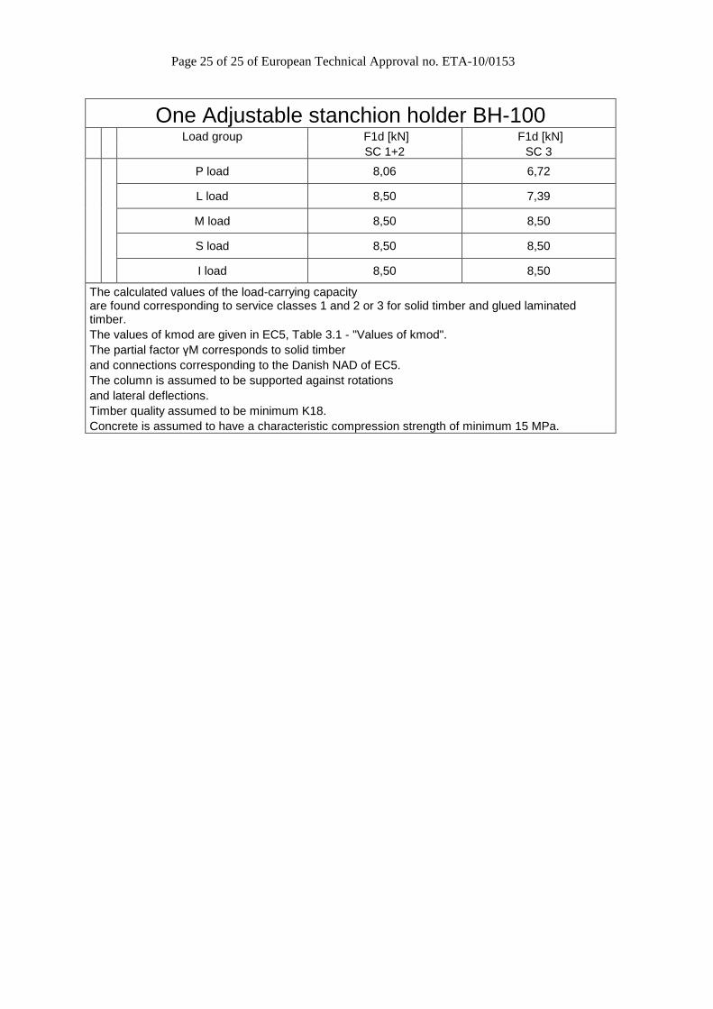
One Adjustable stanchion holder BH-100 Load group F1d [kN] F1d [kN] SC 1+2 SC 3
P load 8,06 6,72
L load 8,50 7,39
M load 8,50 8,50
S load 8,50 8,50
I load 8,50 8,50
The calculated values of the load-carrying capacity are found corresponding to service classes 1 and 2 or 3 for solid timber and glued laminated timber. The values of kmod are given in EC5, Table 3.1 - "Values of kmod". The partial factor γM corresponds to solid timber and connections corresponding to the Danish NAD of EC5. The column is assumed to be supported against rotations and lateral deflections. Timber quality assumed to be minimum K18. Concrete is assumed to have a characteristic compression strength of minimum 15 MPa.