ETA-Danmark A/S Göteborg Plads 1 DK-2150 Nordhavn Tel. +45 72 24 59 00 Fax +45 72 24 59 04 Internet www.etadanmark.dk Authorised and notified according to Article 29 of the Regulation (EU) No 305/2011 of the European Parliament and of the Council of 9 March 2011 MEMBER OF EOTA European Technical Assessment ETA-06/0270 of 2020/01/07 I General Part Technical Assessment Body issuing the ETA and designated according to Article 29 of the Regulation (EU) No 305/2011: ETA-Danmark A/S Trade name of the construction product: Simpson Strong-Tie Joist Hangers See type numbers in section II.1 of the ETA Product family to which the above construction product belongs: Three-dimensional nailing plate (Joist hanger for wood to wood connections and wood to concrete or steel connections) Manufacturer: SIMPSON STRONG-TIE Int. Ltd For local branch refer to www.strongtie.eu Manufacturing plant: SIMPSON STRONG-TIE Manufacturing facilities This European Technical Assessment contains: 216 pages including 4 annexes which form an integral part of the document This European Technical Assessment is issued in accordance with Regulation (EU) No 305/2011, on the basis of: Guideline for European Technical Approval (ETAG) No. 015 Three Dimensional Nailing Plates, April 2013, used as European Assessment Document (EAD). This version replaces: The ETA with the same number issued on 2018-02-13
Transcript
ETA-Danmark A/S Göteborg Plads 1 DK-2150 Nordhavn Tel. +45 72 24 59 00 Fax +45 72 24 59 04 Internet www.etadanmark.dk
Authorised and notified according to Article 29 of the Regulation (EU) No 305/2011 of the European Parliament and of the Council of 9 March 2011
MEMBER OF EOTA
European Technical Assessment ETA-06/0270 of 2020/01/07
I General Part
Technical Assessment Body issuing the ETA and designated according to Article 29 of the Regulation (EU) No 305/2011: ETA-Danmark A/S
Trade name of the construction product:
Simpson Strong-Tie Joist Hangers See type numbers in section II.1 of the ETA
Product family to which the above construction product belongs:
Three-dimensional nailing plate (Joist hanger for wood to wood connections and wood to concrete or steel connections)
Manufacturer: SIMPSON STRONG-TIE Int. Ltd For local branch refer to www.strongtie.eu
Page 3 of 216 of European Technical Assessment no. ETA-06/0270, issued on 2020-01-07
3
D3 BSD Joist hanger 63
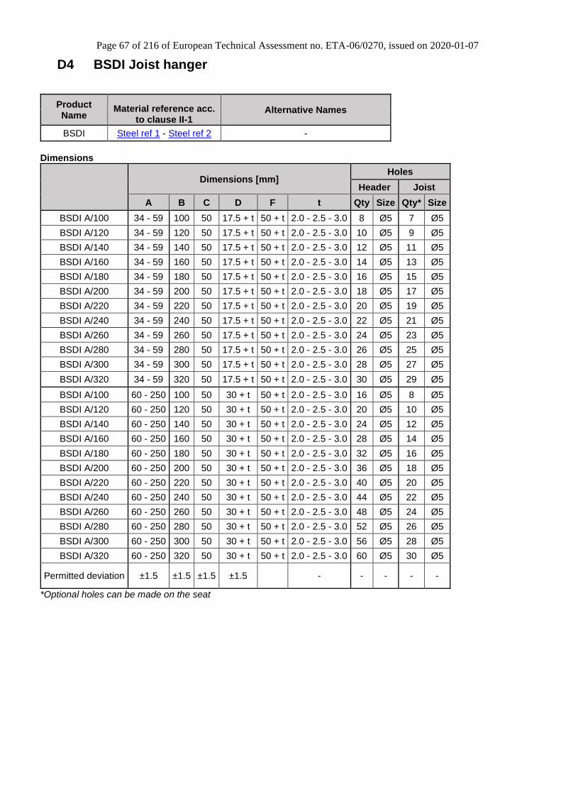
D4 BSDI Joist hanger 67
D5 BSI Joist hanger 69
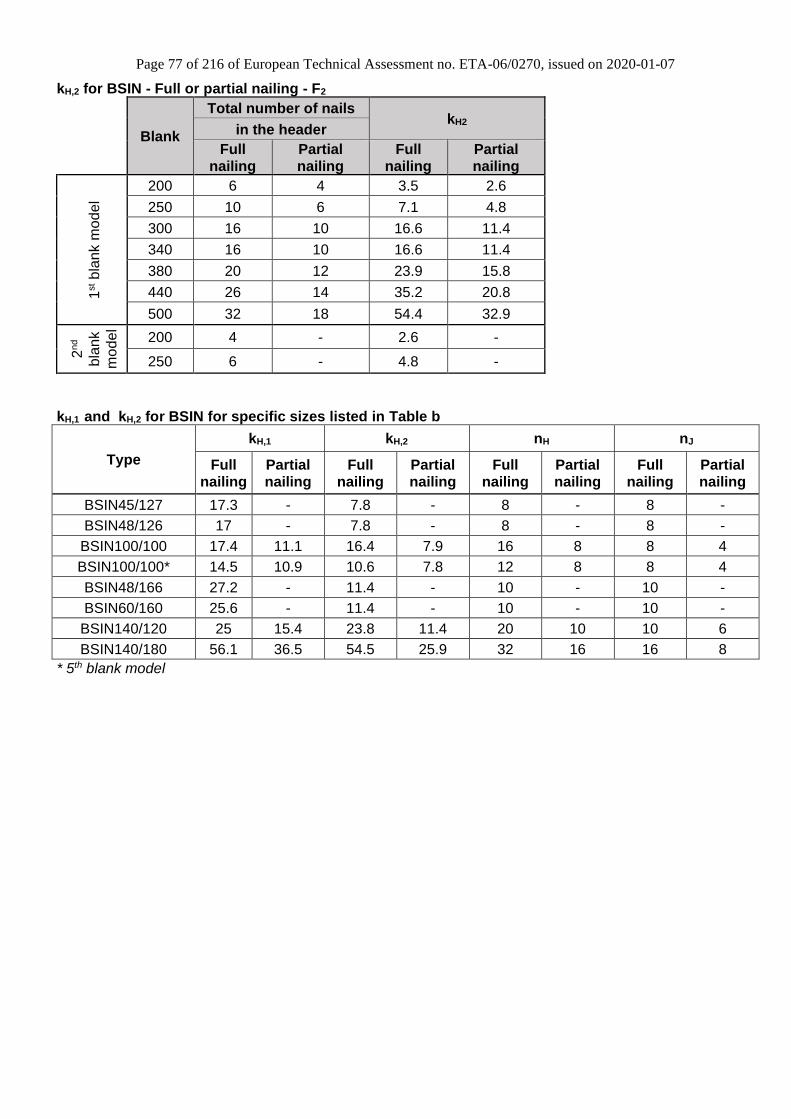
D6 BSIN Joist hanger 72
D7 BSIL Joist hanger 78
D8 BSN Joist hanger 80
D9 BSNN Joist hanger 84
D10 BSS Joist hanger 88
D11 ETC Truss connector 92
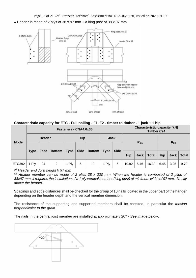
D12 ETC392 Truss Connector 95
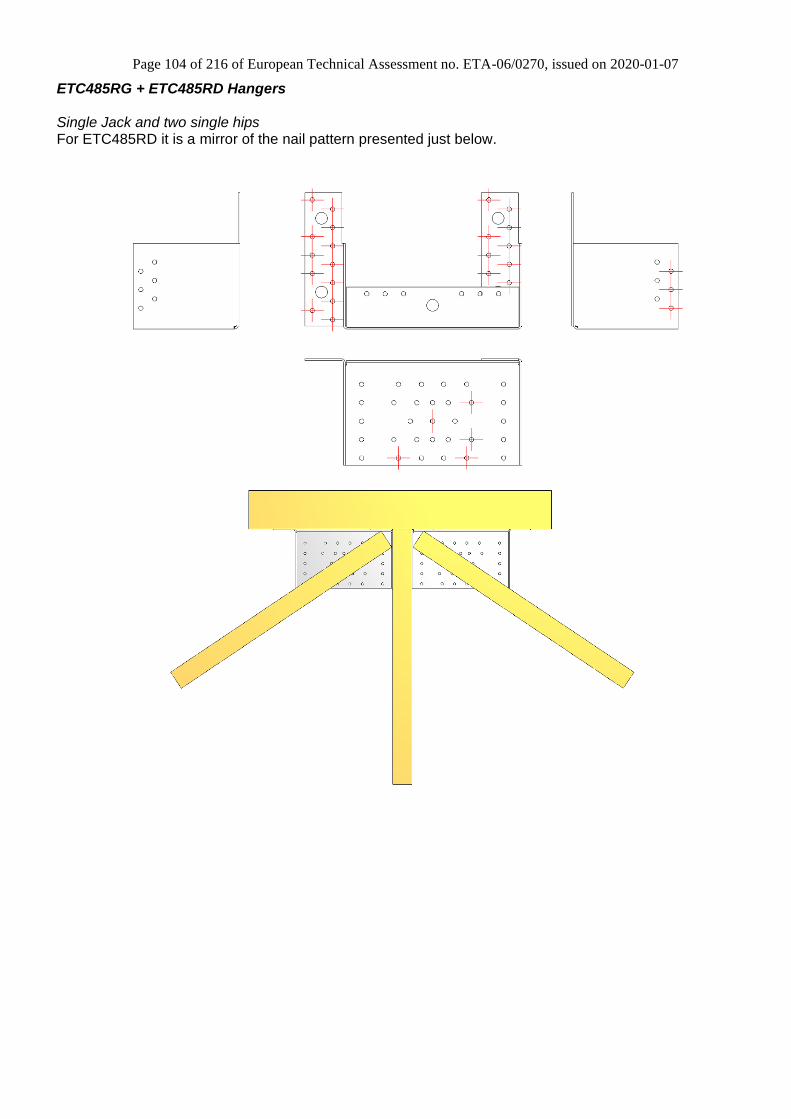
D13 ETC G/D Truss Connector 102
D14 GBE Joist hanger 105
D15 GBI Joist hanger 107
D16 GLE Joist hanger 109
D17 GLE-AL Joist hanger 117
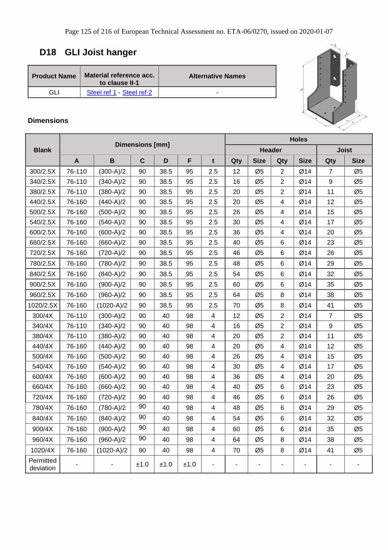
D18 GLI Joist hanger 125
D19 GLI-AL Joist hanger 127
Dimensions 127
D20 GSE Joist hanger 129
D21 GSE-AL Joist hanger 139
D22 GSEXL Joist hanger 144
D23 GSI Joist hanger 145
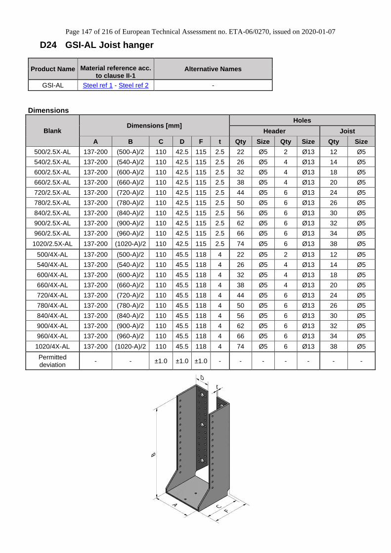
D24 GSI-AL Joist hanger 147
D25 HGUQ Joist hanger 149
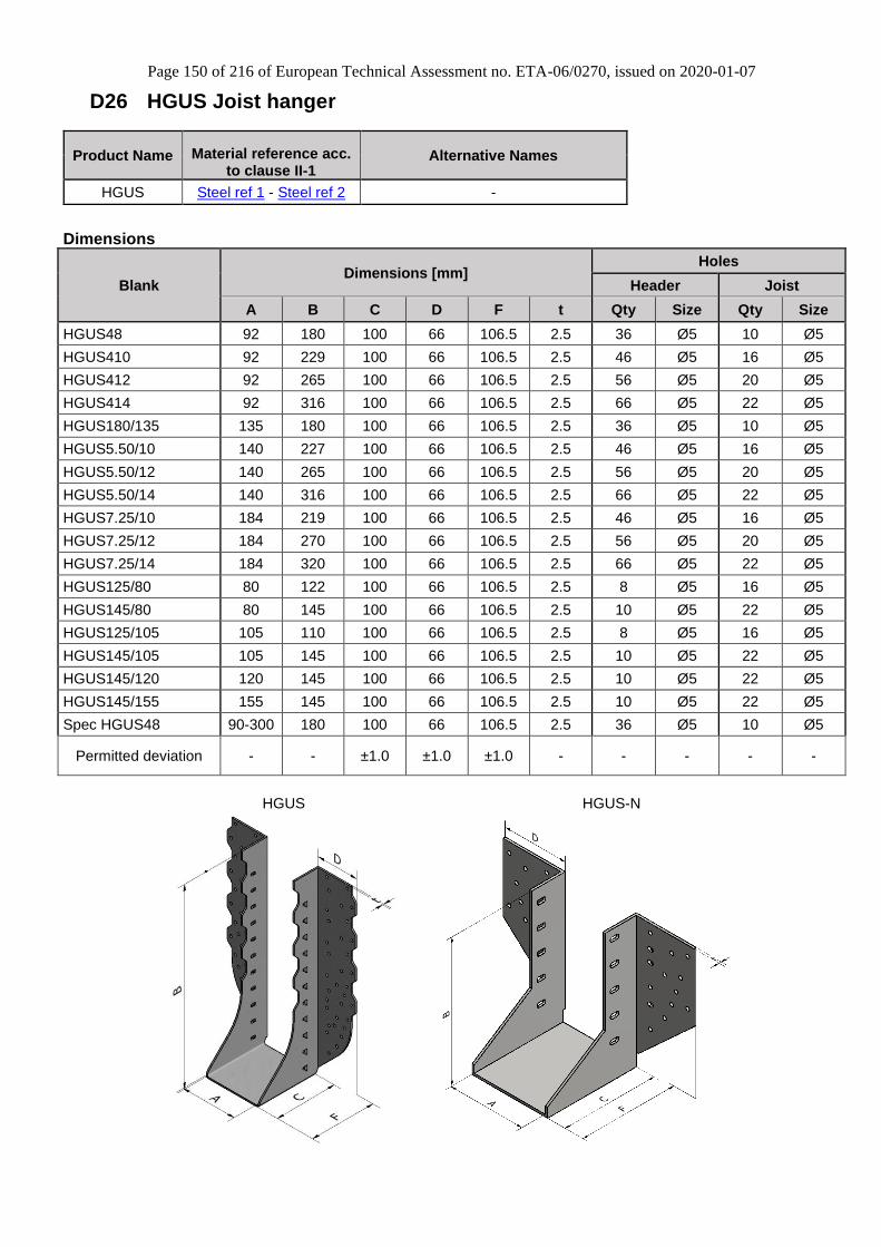
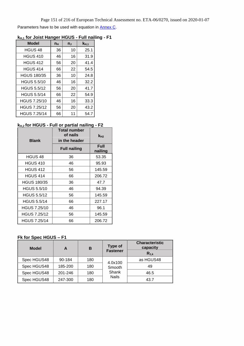
D26 HGUS Joist hanger 150
D27 JHA270 Straps hanger 152
D28 JHA450 Straps hanger 154
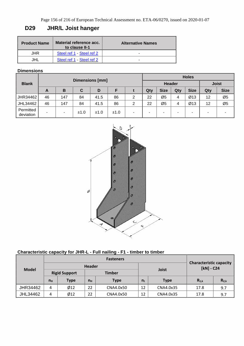
D29 JHR/L Joist hanger 156
D30 LUP Joist hanger 157
D31 MF Joist hanger 158
D32 MH Joist hanger 159
Page 4 of 216 of European Technical Assessment no. ETA-06/0270, issued on 2020-01-07
4
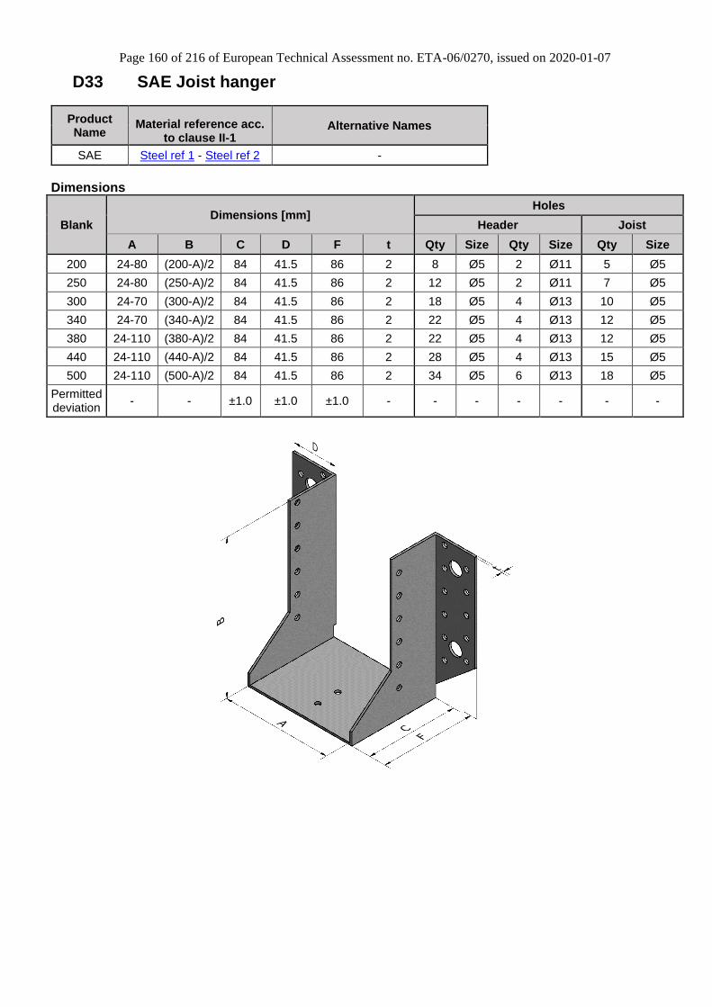
D33 SAE Joist hanger 160
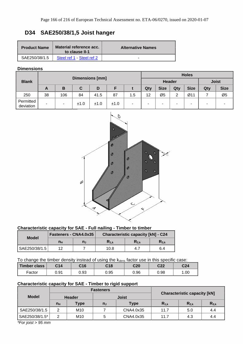
D34 SAE250/38/1,5 Joist hanger 166
D35 SAE590, SAE620 and SAE690 Joist hanger 168
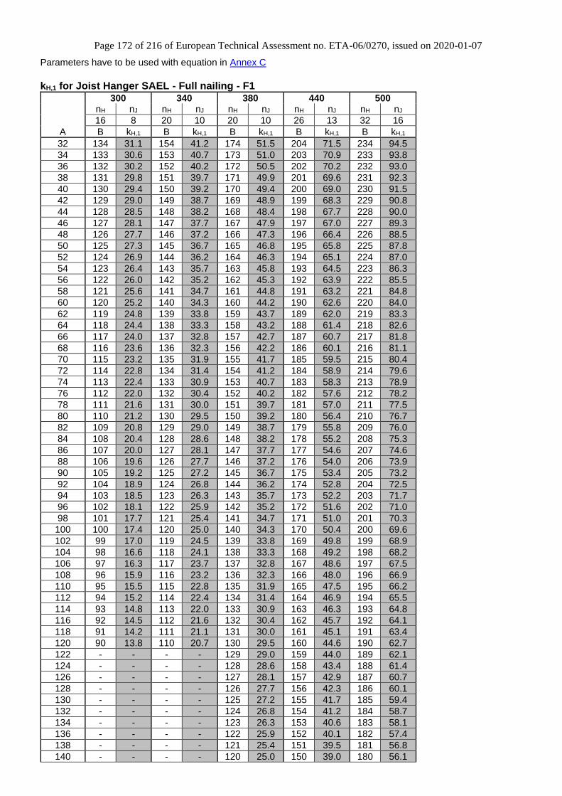
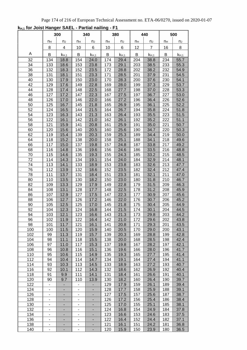
D36 SAEL Joist hanger 171
D37 SAI Joist hanger 177
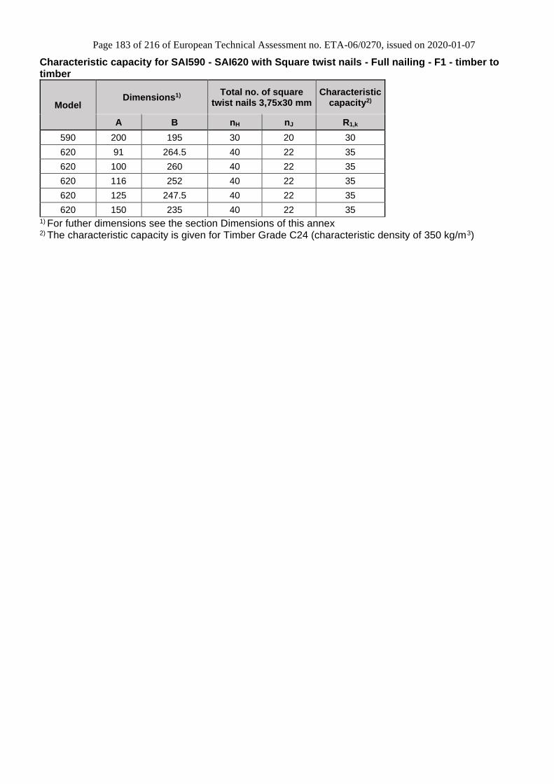
D38 SAI590, SAI620 Joist hanger 182
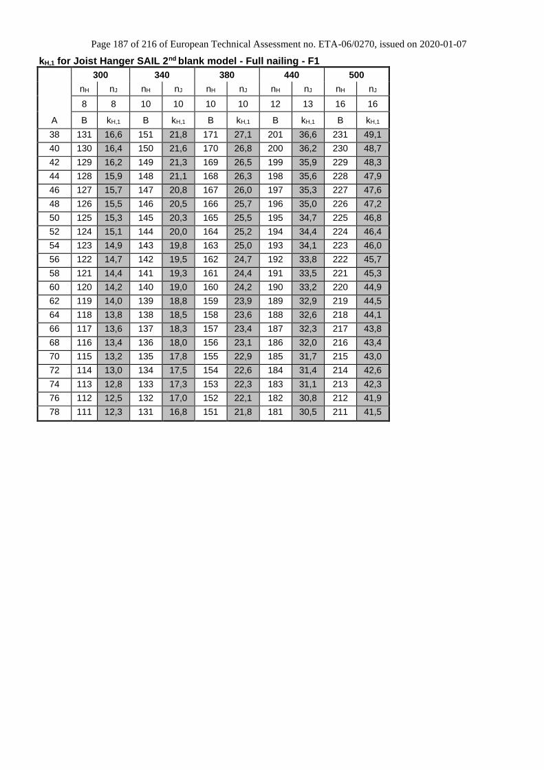
D39 SAIL Joist hanger 184
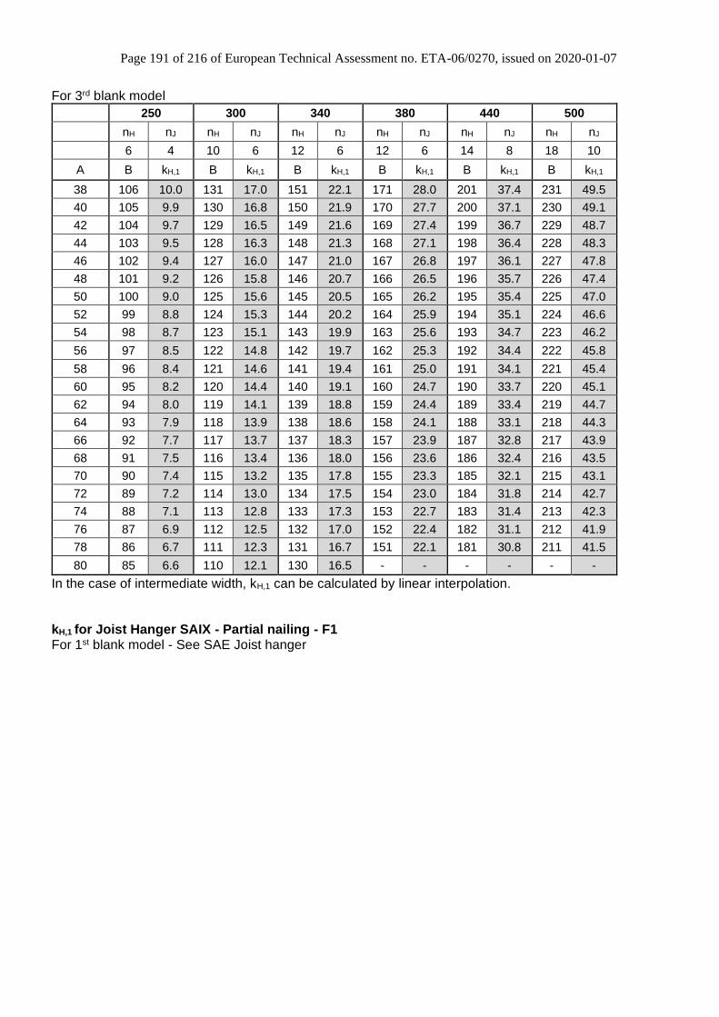
D40 SAIX Joist hanger 189
D41 SAMI/4X Joist hanger 194
D42 SBE Joist hanger 195
D43 SBE45/168/TF Joist hanger 200
D44 SBG/SLE Joist hanger 201
D45 SDED/G and BNS2P Joist hanger 204
D46 SHT Strap hanger 205
D47 SJH Joist hanger 206
D48 TFU Joist hanger 208
D49 THA Straps hanger 213
D50 THAI Straps hanger 215
Page 5 of 216 of European Technical Assessment no. ETA-06/0270, issued on 2020-01-07
5
Translations of this European Technical
Assessment in other languages shall fully
correspond to the original issued document and
should be identified as such.
Communication of this European Technical Assessment, including transmission by electronic means, shall be in full (excepted the confidential Annex(es) referred to above). However, partial reproduction may be made, with the written consent of the issuing Technical Assessment Body. Any partial reproduction has to be identified as such.
Page 6 of 216 of European Technical Assessment no. ETA-06/0270, issued on 2020-01-07
6
II SPECIFIC PART OF THE EUROPEAN TECHNICAL ASSESSMENT
1 Technical description of product and intended use
Simpson Strong-Tie joist hangers type BSD, BSN, BSNN, BSIN, BSS, ETC, GBE, GBI, GLE, GLE-AL, GSE, GSE-AL, HGUQ, HGUS, LUP, MF, MH, SAE, SAE590, SAE620, SAE690, SAEL, SAEX, SBE, SBG/SLE, SJH and TFU are one-piece non-welded, face-fixed external flanges joist hangers to be used in timber-to-timber connections as well as connections between a timber joist and a concrete structure or a steel member. Simpson Strong-Tie joist hangers type GSEXL and SAMI/4X are one-piece non-welded, face-fixed external flanges joist hangers to be used in connections between a timber joist and a concrete structure or a steel member. Simpson Strong-Tie joist hangers type BSI, BSDI, SAI, SAIL, SAIX, GSI, GSI-AL, GLI, GLI-AL and BSIL are one-piece non-welded, face-fixed, internal flanges joist hangers to be used in timber-to-timber connections. Simpson Strong-Tie joist hangers type JHR, JHL, ETCG and ETCD are one-piece non-welded, face-fixed, both external and internal flanges joist hangers to be used in timber-to-timber connections. Simpson Strong-Tie joist hangers type BSN2P, SDED and SDEG are two-pieces non-welded, face-fixed external flanges joist hanger to be used in timber to timber connections as well as connection between a timber and a concrete structure or a steel member. Simpson Strong-Tie AG703, AG713, JHA, SHT, THA and THAI, joist hangers are one-piece, non-
welded, face-fixed or wrapped-over timber-to-timber joist hangers. They are connected to a header to support a timber joist with a range of nails.
The materials for headers and joists can be of solid timber, glued laminated timber or engineered timber products such as LVL or I-joist (fitted with backer blocks if used for the header). The joist hangers are made from pre-galvanized steel Grade S250GD + Z (min Z275) according to EN 10346 or pre-galvanized steel with a minimum characteristic 0.2% yield stress of 250MPa, a minimum ultimate tensile strength of 330MPa and a minimum Elongation of 19%, with tolerances according to EN 10143 except if another material is specified (named “Steel ref 1” in the rest of the document). Material, dimensions and nails positions are detailed in Annex D and typical installations are detailed in Annex B. By default all the products are made out of this material except when specified. All joist hangers can also be produced from stainless steel number 1.4401, 1.4404, 1.4521, 1.4301 or 1.4509 according to EN 10088-2 or a stainless steel with a minimum characteristic 0.2% yield stress of 240 MPa, a minimum 1.0% yield stress of 270 MPa and a minimum ultimate tensile strength of 530 MPa (named “Steel ref 2” in the rest of the document). If no name is clearly specified, product variant made with stainless steel have generally the same name with a S (as Stainless) at the end. Some joist hangers may be produced from steel grade S235JR according to EN 10025-2 (named “Steel ref 3” in the rest of the document). In this case, an additional coating must be added such as hot dip galvanizing or painting. Some additional coatings allow to reach service class 3.
2 Specification of the intended use in accordance with the applicable EAD
The joist hangers are intended for use in making end-grain to side-grain connections in load bearing timber structures, as a connection between a wood based joist and a solid timber or wood based header, where requirements for mechanical resistance and stability and safety in use in the sense of the Basic Works Requirements 1 and 4 of Regulation (EU) 305/2011 shall be fulfilled. They are also intended for use in making an end-grain connection between a timber joist and a concrete structure or a steel member.
Page 7 of 216 of European Technical Assessment no. ETA-06/0270, issued on 2020-01-07
7
The joist hangers can be installed as connections between wood based members such as:
• Structural solid timber classified to C14-C40 according to EN 338 / EN 14081,
• Glulam classified to GL24-GL36 according to EN 1194 / EN 14080,
• LVL according to EN 14374,
• Parallam PSL,
• Intrallam LSL,
• Duo- and Triobalken,
• Layered wood plates,
• Kreuzbalken with minimum thickness of 80 mm
• I-beams with backer blocks on both sides of the web in the header and web stiffeners in the joist
• Plywood according to EN 636
• Cross Laminated timber according to EN 16351 However, the calculation methods are only allowed for a characteristic wood density of up to 460 kg/m3. Even though the wood based material may have a larger density, this must not be used in the formulas for the load-carrying capacities of the fasteners. When used on CLT only CSA screws shall be used with the connectors. The edge distance and spacing of each CSA screw must be checked according to the specifications given by the manufacturer of the timber. If nothing is specified, edge distance and spacing must be in accordance to the outer layer of the CLT panels. Annex C defines the directions of forces and also states the formulas for the characteristic load-carrying capacities of the joist hanger connections. The design of the connections shall be in accordance with Eurocode 5 or a similar national Timber Code. The joist hangers are intended for use for connections subject to static or quasi static loading. The scope of the hangers regarding resistance to corrosion shall be defined according to national provisions that apply at the installation site considering environmental conditions and in conjunction with the admissible service conditions according to EN 1995-1-1 and the admissible corrosivity category as described and defined in EN ISO 12944-2 The provisions made in this European Technical Assessment are based on an assumed intended working life of the post bases brackets of 50 years.
The indications given on the working life cannot be interpreted as a guarantee given by the producer or Assessment Body, but are to be regarded only as a means for choosing the right products in relation to the expected economically reasonable working life of the works.
Page 8 of 216 of European Technical Assessment no. ETA-06/0270, issued on 2020-01-07
8
3 Characteristics of product and assessment
Characteristic
Assessment of characteristic
3.1 Mechanical resistance and stability*) (BWR1)
Characteristic load-carrying capacity
See Annex D
Stiffness
No performance assessed
Ductility in cyclic testing
No performance assessed
3.2 Safety in case of fire (BWR2)
Reaction to fire
The joist hangers are made from steel steel classified as class A1 in accordance with EN 13501-1 and Commission Delegated Regulation 2016/364
3.3 Hygiene, health and the environment (BWR3)
Influence on air quality
No performance assessed
3.7 Sustainable use of natural resources (BWR7)
No performance assessed
3.8 General aspects related to the performance of the product
The joist hangers have been assessed as having satisfactory durability and serviceability when used in timber structures using the timber species described in Eurocode 5 and subject to the conditions defined by service class 1 and 2
Identification
See Annex D
*) See additional information in section 3.9 – 3.12.
Page 9 of 216 of European Technical Assessment no. ETA-06/0270, issued on 2020-01-07
9
3.9 Methods of verification Safety principles and partial factors The characteristic load-carrying capacities are based on the characteristic values of the nail connections and the joist hangers. To obtain design values the capacities have to be divided by different partial factors for the material properties, the nail connection in addition multiplied with the coefficient kmod. According to EN 1990 (Eurocode – Basis of design) paragraph 6.3.5 the design value of load-carrying capacity may be determined by reducing the characteristic values of the load-carrying capacity with different partial factors. Thus, the characteristic values of the load–carrying capacity are determined also for timber failure FRk,H (obtaining the embedment strength of nails subjected to shear or the withdrawal capacity of the most loaded nail, respectively) as well as for steel plate failure FRk,S. The design value of the load–carrying capacity is the smaller value of both load–carrying capacities.
mod Rk,H Rk,SRd
M,H M,S
k F FF min ;
=
Therefore, for timber failure the load duration class and the service class are included. The different
partial factors M for steel or timber, respectively, are also correctly taken into account. 3.10 Mechanical resistance and stability See Annex C for characteristic load-carrying capacities of the joist hangers. The characteristic capacities of the joist hangers are determined by calculation assisted by testing or only testing as described in the EOTA Guideline 015 clause 5.1.2. They should be used for designs in accordance with Eurocode 5 or a similar national Timber Code. The design models allow the use of fasteners described in the table in Annex C3: The characteristic load-carrying capacities of the products shall be calculated in accordance with the manufacturer’s design code, extracts of which are given in Annex C4. The design code has been derived in accordance with ETAG 015 and Eurocode 5 (2008). The calculated values should be used for designs in accordance with Eurocode 5 or a similar national Timber Code. These values are based on the assumption that there is a maximum gap of 3 mm
between the timber members, the members are laterally restrained and wane is not present in the timber at the joint. The hangers shall be used with the fasteners specified in Annex C3. Furthermore, the Face mount hangers types BSD, BSN, BSNN, BSIL, BSIN, BSS, JHR/L, SAE, SAEL, SAEX, SAIX, SDED/G, GSE, GSE-AL, GSEXL, MF, SAMI/4X, GLE, GLE-AL, ETC, GBE, TFU, SBE, SBG, SLE and SJH can be fastened to a concrete structure or steel member with 8 to 12 mm diameter bolts in holes with a diameter up to 2 mm larger than the bolt. No performance has been determined in relation to the joint’s stiffness properties - to be used for the analysis of the serviceability limit state. No performance has been determined in relation to ductility of a joint under cyclic testing. The contribution to the performance of structures in seismic zones, therefore, has not been assessed. 3.11 Aspects related to the performance of the product 3.11.1 Corrosion protection in service class 1 and 2. In accordance with ETAG 015, joist hangers have a zinc coating weight of min Z275. Steel employed is S250GD with min Z275 according to EN 10346:2009. 3.11.2 Corrosion protection in service class 3. In accordance with Eurocode 5, joist hangers are made from stainless steel number 1.4401, 1.4404, 1.4521, 1.4301 or 1.4509 according to EN 10088-2 or a stainless steel with a minimum characteristic 0.2% yield stress of 240 MPa, a minimum 1.0% yield stress of 270 MPa and a minimum ultimate tensile strength of 530 MPa. The nails or screws shall be produced from stainless steel. Joist hangers coated with hot dip galvanisation, or made of S250GD steel with zinc coating ZM310 according to EN 10346:2009, can also be used in service class 3 according to Eurocode 5. 3.12 General aspects related to the use of the product Simpson Strong-Tie joist hangers types AG703, AG713, BSD, BSDI, BSN, BSNN, BSI, BSIL, BSIN, BSS, ETC, ETC G/D, GBE, GBI, GLE, GLE-AL, GLI, GLI-AL, GSE, GSE-AL, GSEXL, GSI, GSI-AL, HGUQ, HGUS, JHA270, JHA450, JHR/L, LUP, MF,
Page 10 of 216 of European Technical Assessment no. ETA-06/0270, issued on 2020-01-07
10
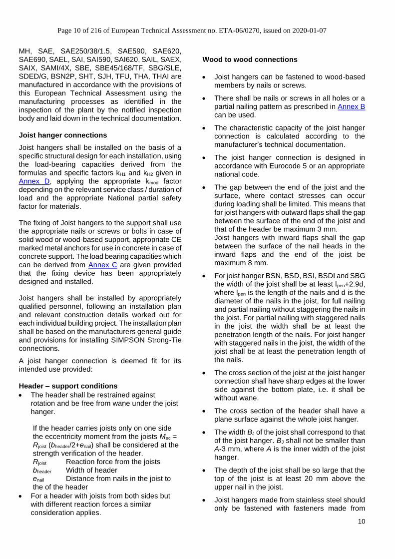
MH, SAE, SAE250/38/1.5, SAE590, SAE620, SAE690, SAEL, SAI, SAI590, SAI620, SAIL, SAEX, SAIX, SAMI/4X, SBE, SBE45/168/TF, SBG/SLE, SDED/G, BSN2P, SHT, SJH, TFU, THA, THAI are manufactured in accordance with the provisions of this European Technical Assessment using the manufacturing processes as identified in the inspection of the plant by the notified inspection body and laid down in the technical documentation. Joist hanger connections
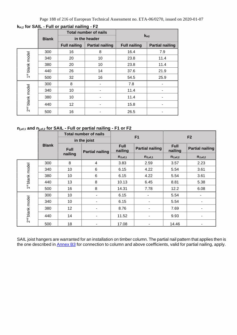
Joist hangers shall be installed on the basis of a specific structural design for each installation, using the load-bearing capacities derived from the formulas and specific factors kH1 and kH2 given in Annex D, applying the appropriate kmod factor depending on the relevant service class / duration of load and the appropriate National partial safety factor for materials.
The fixing of Joist hangers to the support shall use the appropriate nails or screws or bolts in case of solid wood or wood-based support, appropriate CE marked metal anchors for use in concrete in case of concrete support. The load bearing capacities which can be derived from Annex C are given provided that the fixing device has been appropriately designed and installed.
Joist hangers shall be installed by appropriately qualified personnel, following an installation plan and relevant construction details worked out for each individual building project. The installation plan shall be based on the manufacturers general guide and provisions for installing SIMPSON Strong-Tie connections.
A joist hanger connection is deemed fit for its intended use provided: Header – support conditions
• The header shall be restrained against rotation and be free from wane under the joist hanger.
If the header carries joists only on one side the eccentricity moment from the joists Mec = Rjoist (bheader/2+enail) shall be considered at the strength verification of the header. Rjoist Reaction force from the joists
bheader Width of header
enail Distance from nails in the joist to the of the header
• For a header with joists from both sides but with different reaction forces a similar consideration applies.
Wood to wood connections
• Joist hangers can be fastened to wood-based members by nails or screws.
• There shall be nails or screws in all holes or a partial nailing pattern as prescribed in Annex B can be used.
• The characteristic capacity of the joist hanger connection is calculated according to the manufacturer’s technical documentation.
• The joist hanger connection is designed in accordance with Eurocode 5 or an appropriate national code.
• The gap between the end of the joist and the surface, where contact stresses can occur during loading shall be limited. This means that for joist hangers with outward flaps shall the gap between the surface of the end of the joist and that of the header be maximum 3 mm. Joist hangers with inward flaps shall the gap between the surface of the nail heads in the inward flaps and the end of the joist be maximum 8 mm.
• For joist hanger BSN, BSD, BSI, BSDI and SBG the width of the joist shall be at least lpen+2.9d, where lpen is the length of the nails and d is the diameter of the nails in the joist, for full nailing and partial nailing without staggering the nails in the joist. For partial nailing with staggered nails in the joist the width shall be at least the penetration length of the nails. For joist hanger with staggered nails in the joist, the width of the joist shall be at least the penetration length of the nails.
• The cross section of the joist at the joist hanger connection shall have sharp edges at the lower side against the bottom plate, i.e. it shall be without wane.
• The cross section of the header shall have a plane surface against the whole joist hanger.
• The width BJ of the joist shall correspond to that of the joist hanger. BJ shall not be smaller than A-3 mm, where A is the inner width of the joist hanger.
• The depth of the joist shall be so large that the top of the joist is at least 20 mm above the upper nail in the joist.
• Joist hangers made from stainless steel should only be fastened with fasteners made from
Page 11 of 216 of European Technical Assessment no. ETA-06/0270, issued on 2020-01-07
11
suitable stainless steel. Zinc-coated joist hangers shall not be fastened with fasteners of stainless steel.
• Nails or screws to be used shall have a diameter, which fits the holes of the joist hangers. Round nails shall have a diameter which is not smaller than the diameter of the hole minus 1 mm. Nails with square cross section shall have a side length not smaller than the hole diameter minus 1,25 mm.
Straps hangers shall be installed to meet the following requirements:
• The hanger is connected to header using the specified nails in Annex C3. The hanger side and back flanges may have a slight splay from nesting within the packing. It is essential to hold the hanger square to the header before nailing.
▪ Where it is necessary to wrap the straps over the header, a minimum wrap over of 45 mm is required for the JHA and THA and 65 mm for the THAI, AG703 and AG713 to achieve the minimum nailing specification.
▪ For I-joist headers backer blocks of softwood, OSB or plywood shall be installed (see Annex B).
▪ The size, material and installation details of the backer blocks shall be in accordance to the joist manufacturer’s specifications.
▪ The joist is installed in the hanger ensuring it is free from wane and the gap between the end of joist and header does not exceed 3 mm.
▪ The specified joist nails are installed. For instances where double shear nailing is specified, ensure that the correct nail is installed into the joist at an angle of 45°. For the THAI, the specified nail is to be driven downwards at an angle of 45°, into the joist.
▪ When the supported member is an I-joist it will be necessary to install web stiffeners to the end of the joist if the top flange is not laterally restrained by the hanger side flanges. Refer to joist manufacturer’s literature for details of web stiffener installation.
▪ Header is restrained against rotation before application of full loading.
Wood to concrete or steel The above mentioned rules for wood-to-wood connections are applicable also for the connections between the joist and the joist hanger.
• The joist hanger shall be in close contact with the concrete or steel over the whole face. There shall be no intermediate layers in between.
• The gap between the end of the joist and the surface, where contact stresses can occur during loading shall be limited. This means that the gap between the surface of the end of the joist and that of the concrete or steel shall be maximum 3 mm.
• The bolt shall have a diameter not less than the hole diameter minus 2 mm.
• The bolts shall be placed symmetrically about the vertical symmetry line. There shall always be bolts in the 2 upper holes.
• For concrete, the bolts shall use washers recommended with the mechanical anchor delivery by the suppliers. For steel, the upper bolts shall have washer Ø18 mm minimum.
Page 12 of 216 of European Technical Assessment no. ETA-06/0270, issued on 2020-01-07
12
4 Assessment and verification of constancy of performance (AVCP)
4.1 AVCP system According to the decision 97/638/EC of the European Commission1, as amended, the system(s) of assessment and verification of constancy of performance (see Annex V to Regulation (EU) No 305/2011) is 2+.
5 Technical details necessary for the implementation of the AVCP system, as foreseen in the applicable EAD
Technical details necessary for the implementation of the AVCP system are laid down in the control plan deposited at ETA-Danmark prior to CE marking
Issued in Copenhagen on 2020-01-07 by
Thomas Bruun Managing Director, ETA-Danmark
Page 13 of 216 of European Technical Assessment no. ETA-06/0270, issued on 2020-01-07
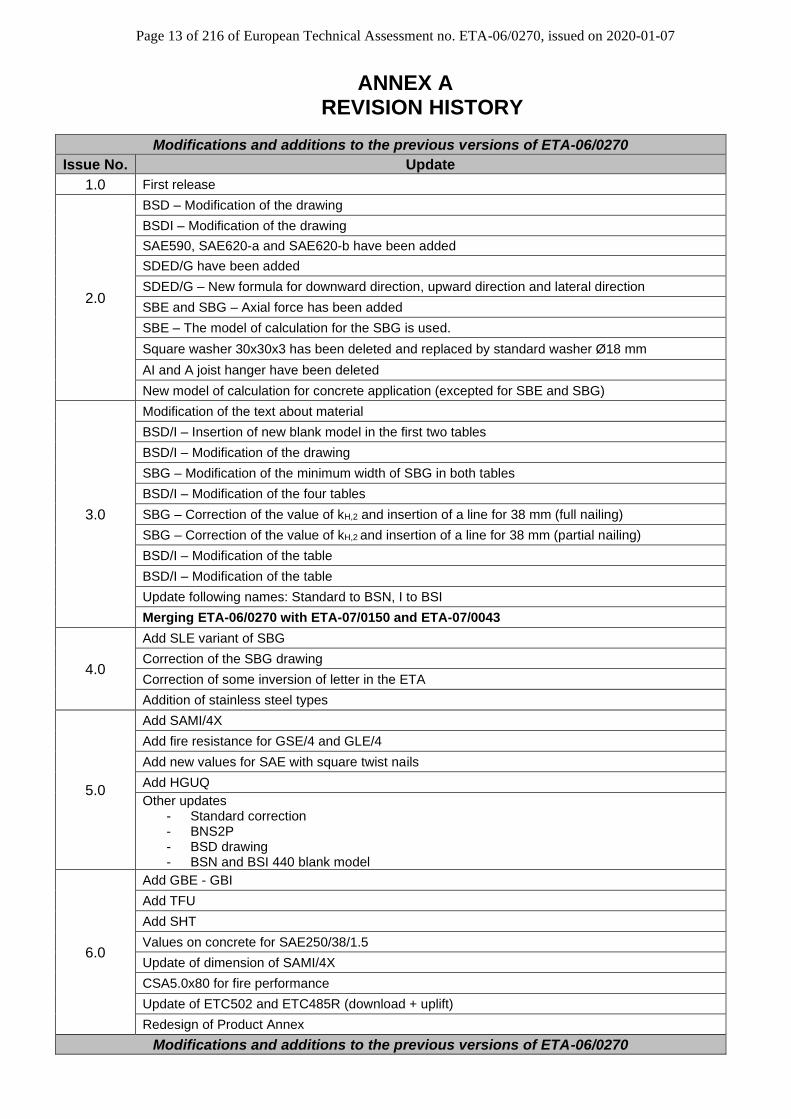
ANNEX A REVISION HISTORY
Modifications and additions to the previous versions of ETA-06/0270
Issue No. Update
1.0 First release
2.0
BSD – Modification of the drawing
BSDI – Modification of the drawing
SAE590, SAE620-a and SAE620-b have been added
SDED/G have been added
SDED/G – New formula for downward direction, upward direction and lateral direction
SBE and SBG – Axial force has been added
SBE – The model of calculation for the SBG is used.
Square washer 30x30x3 has been deleted and replaced by standard washer Ø18 mm
AI and A joist hanger have been deleted
New model of calculation for concrete application (excepted for SBE and SBG)
3.0
Modification of the text about material
BSD/I – Insertion of new blank model in the first two tables
BSD/I – Modification of the drawing
SBG – Modification of the minimum width of SBG in both tables
BSD/I – Modification of the four tables
SBG – Correction of the value of kH,2 and insertion of a line for 38 mm (full nailing)
SBG – Correction of the value of kH,2 and insertion of a line for 38 mm (partial nailing)
BSD/I – Modification of the table
BSD/I – Modification of the table
Update following names: Standard to BSN, I to BSI
Merging ETA-06/0270 with ETA-07/0150 and ETA-07/0043
4.0
Add SLE variant of SBG
Correction of the SBG drawing
Correction of some inversion of letter in the ETA
Addition of stainless steel types
5.0
Add SAMI/4X
Add fire resistance for GSE/4 and GLE/4
Add new values for SAE with square twist nails
Add HGUQ
Other updates - Standard correction - BNS2P - BSD drawing - BSN and BSI 440 blank model
6.0
Add GBE - GBI
Add TFU
Add SHT
Values on concrete for SAE250/38/1.5
Update of dimension of SAMI/4X
CSA5.0x80 for fire performance
Update of ETC502 and ETC485R (download + uplift)
Redesign of Product Annex
Modifications and additions to the previous versions of ETA-06/0270
Page 14 of 216 of European Technical Assessment no. ETA-06/0270, issued on 2020-01-07
Issue No. Update
7.0
Add ZM310 for service class 3
Add SSH/SSF screws nail pattern indications, specifications and capacities. Add also tables with SSH/SSF screws for BSNN, GLE, GSE, GSE-AL, SAE, SAEL and SBE joist hangers.
Remove ARS 4,0x50 values table
Indicate that the 3rd part of Eq.6 [7A √…] is in N
Add BSNN to the header and below Eq.17
Add "nH,eff is the number of nails in the first row close to the bending line" below Eq.17
Add “nh the number of bolts on each flange on the header” below Eq.33
Add “when connected to timber, zmax is reduced by 20 mm” below Eq.43
Add “Fanchor,Rk is the resistance of the anchors group / bolts group in case of timber to timber connection” below Eq.46
Add “anchors/bolts” and for timber to timber connections via bolts, the centre of rotation is 20 mm above the bottom plate for Eq.53
BSIN – Add BSIN100/100 modified version and associated data
BSN – Correct heights: for blank 280 mm, height B of 90 mm instead of 140 mm
BSNN – Add blanks 300, 340 and 380 mm new version and associated data
ETC – Correct number of header nails in the table of Fk capacities: for ETC502 (a), 25 mm instead of 15 mm and for ETC502 (c), 15 instead of 25 mm
ETC – Add ETC392
GBE – Update GBE parameters
GLE / GLI – Add new blanks and dimensions
Add GLE-AL and GLI-AL joist hangers
GSE – Correct holes joist quantity of GSE900/2,5X and GSE900/4X from 38 to 36
GSI – Update dimension Amax of GSI from 140 to 136 and dimension Amin of GSI-AL from 135 to 137
SAE, SAEL, SAI and SAIL – Add a mention to partial nailing of posts
SAEL – Correct SAEL width in dimensions table
SAI – Correct width of SAI620-a and SAI620-b, respectively from 90 to 100 and from 101 to 200 mm
SAIX – Add alternative name SAEX for external flanges joist hangers
SAIX - Add ZM310 to SAEX and SAIX
Add SJH joist hanger
THAI – Add THAI1200 straps hanger
Add fire resistance for GSE/4 on concrete
Page 15 of 216 of European Technical Assessment no. ETA-06/0270, issued on 2020-01-07
Modifications and additions to the previous versions of ETA-07/0150
Issue No. Updates
1.0 First release
2.0
GSE780/120 - New loads on concrete
HGUS from UK - kH1 and kH2
Calibration factors for GSE and GSI on wood/wood
GSE/GSI - New model for wood/rigid support application (ID151)
kh1 and kh2 are not given for JHL/R. Situation to be clarified. See project F1044
Add HGUQ product range
Change product type in HGUS table in annex 48 (currently refers to GSE)
Change the identity of type IL from blank to width x height (annex 49)
Add 4.0 nails for HGUS range
Add widths up to 300mm for HGUS48
Add axial resistance of GSE/I timber and concrete
3.0
Change the identity of type IL to BSIL and also from blank to width x height
Add HGUQ product range
Add widths up to 300mm for HGUS48 and add Spec HGUS
Change product type in HGUS table in annex 48 (currently refers to GSE)
Add 4.0 nails for HGUS range
Calibration factors for GSE and GSI on wood/wood
GSE/GSI - New model for wood/rigid support application (ID151)
Add axial resistance of GSE/I on timber and concrete
Add ranges ETC – ETC G/D – GSEXL – GLE/GLI
Update following names: IL to BSIL, S to BSS
Modifications and additions to the previous versions of ETA-07/0043
Issue No.
Updates
1.0 First Release
2.0
EN 1195-1-1:2004 changed to EN 1995-1-1:2004 + A1:2008
JHA & THA minimum wrap over changed from 55mm to 45mm
Figure 1 updated: Table 1 split into two tables: Material reference's updated
Table A3 was table 2. Table updated - model number changed & material reference updated.
Figure A3 updated.
Table A4 was table 3. THAI322 added to table: Material reference updated.
Table A5 was table 4.
Table A6 was table 5. Table updated - additional installation configurations added for JHA270, JHA450 & THA
Formula reference numbers added
Formula (2) updated; Formula (3) added; Formula (4) updated
Formula (14) updated; Formula (16) added; Formula (18) updated
Figure A2.10.1 was Figure A1
Definition of symbols table updated - Beff and Leff added
Annex 3. Table 3.1 was table 8; Table 3.2 was table 7; Table 3.3 was table 6; Table 3.4 was table 9
Annex 4. Table updated - Leff, Beff, CHor & Kef added to table; Bmin* removed from table.
Annex 5 added.
3.0 Add AG703 & AG713
Merging ETA-06/0270 with ETA-07/0150 and ETA-07/0043
Page 16 of 216 of European Technical Assessment no. ETA-06/0270, issued on 2020-01-07
ANNEX B TYPICAL INSTALLATIONS
B1 Joist hangers on timber
B2 Joist hanger on rigid support
Page 17 of 216 of European Technical Assessment no. ETA-06/0270, issued on 2020-01-07
B3 Nail Pattern
Full nail fixing: General application
Fill it in all the holes with nails, on the face and the side flanges. Partial nail fixing: General application
● On the side flanges : Place one nail out of two on each side flange, starting from the first hole on the top of the flange. ● On the face flanges : Place the nails on each face flange, on the vertical line next to the folding.
Partial nailing for connection to column The distance between the nails in the direction of the fibre shall be at least 20 mm.
Page 18 of 216 of European Technical Assessment no. ETA-06/0270, issued on 2020-01-07
Fixing with SSH or SSF connector screws:
● On the side flanges : Fill with SSH or SSF connector screws in the face flanges all large holes that fulfil the
minimum spacing stated in annex C3.
● On the face flanges : Fill all holes with Ø4 nails or Ø5 connector screws.
Page 19 of 216 of European Technical Assessment no. ETA-06/0270, issued on 2020-01-07
B4 Conditions for using I-beam headers
When an I-beam is used as header beam it is a condition for the load-carrying capacity, that 2 backer blocks are installed, because it prevents a bending failure of the web in the I-beam as explained in the following. Further, the nails, which normally are nailed in the side of the solid header beam, can instead be nailed into the backer blocks. Therefore, the sum of the thicknesses of the backer blocks and the web shall at least be equal to the length of the nails in the header For both reasons it is important that the backer block supports the underside of the top flange of the header I-beam and is sufficiently connected to the web of the head I-beam. The rope effect results in a tensile force Ft directed toward the edge of the flange. If there are no backer blocks installed, there exists a risk for a bending failure by Mweb at the neck of the web due to the torsion. With at backer block installed the torsional moment will be taken by a compression force Fc,web between the backer block and the underside of the flange and tensile force in the web.
Mweb
Fc,web Backer block Nail
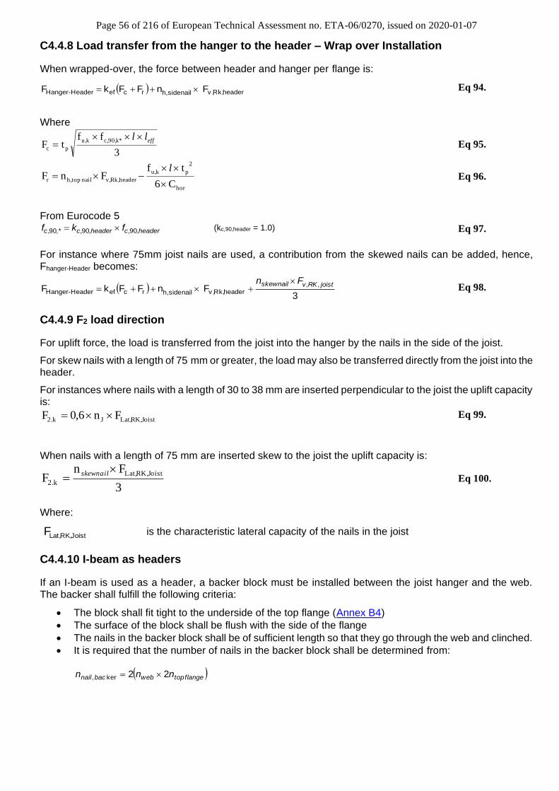
Static model for a vertical force downward. The header beam has been drawn a little away to the right to show the forces acting. The header is shown with the forces and moment acting on it. The surface of the backer block shall be flush with the side of the flange and shall fit tight to the underside of the flange and shall be nailed with sufficient nails to secure, that the backer blocks and the web functions as one piece of solid timber. It is required that the number of nails in the backer block shall be determined from:
headerblcokbacnail nn = 2ker,
Where: nheader is the total number of nails from the joist hanger into the header. If the header has a joist hanger on each side, the number of nails shall be doubled. The nails in the backer block shall have a length so their tip will go through the web and at least 20 mm into the opposite backer block. The I-beam can be prevented from rotation by several means. For example can the wood based panel normally nailed to the top flange and the boards typically nailed to the bottom flange prevent the I-beam from rotating.
Page 20 of 216 of European Technical Assessment no. ETA-06/0270, issued on 2020-01-07
B5 Conditions for using I-beam joists
When an I-beam is used as a joist it is a condition for the load-carrying capacity, that 2 web stiffeners are nailed to the web of the joist, one on each side.
Web stiffener Nail Web stiffeners on the joist at the joist hanger. The web stiffener shall fit to the bottom flange and have a width of 2/3 of the height between the inner sides of the flanges. The surface of the web stiffeners shall be flush with the side of the flange of the joist and shall fit tight to the lower flange and shall be nailed with sufficient nails to secure, that the web stiffeners and the web functions as one piece of solid timber. So, the number of nails in each web stiffener shall be:
joiststifwebnail nn =−,
Where: njoist is the total number of nails from the joist hanger into the joist.
Page 21 of 216 of European Technical Assessment no. ETA-06/0270, issued on 2020-01-07
B6 SJH typical installation
Basic installation on timber, placed diagonally: 1 SJHR + 1 SJHR-F. SJHR shall be placed flush to joist surface.
Installation with reinforcing full threaded screws when nails in joist does not overlap: 1 SJHR + 1 SJHR-F + 1 ESCRFTZ
On rigid support, only configurations where half hangers are placed symmetrically is allowed.
Page 22 of 216 of European Technical Assessment no. ETA-06/0270, issued on 2020-01-07
ANNEX C BASIS OF DESIGN
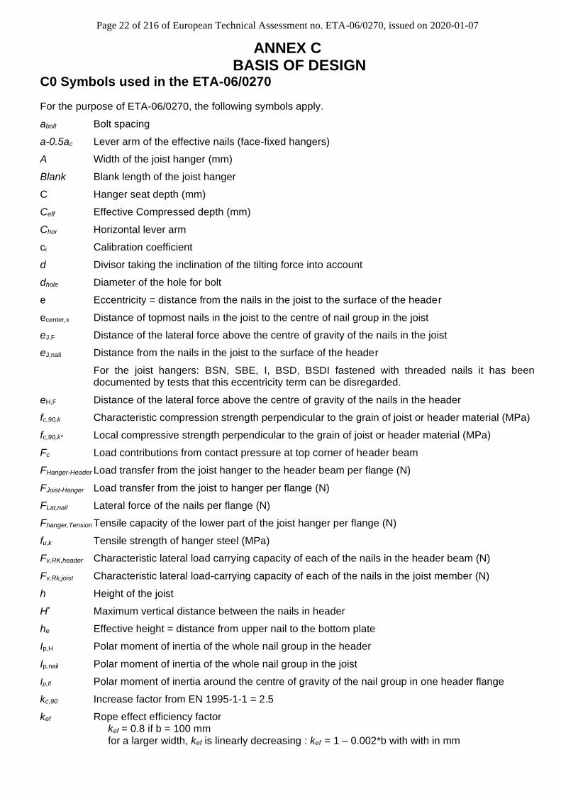
C0 Symbols used in the ETA-06/0270
For the purpose of ETA-06/0270, the following symbols apply.
abolt Bolt spacing
a-0.5ac Lever arm of the effective nails (face-fixed hangers)
A Width of the joist hanger (mm)
Blank Blank length of the joist hanger
C Hanger seat depth (mm)
Ceff Effective Compressed depth (mm)
Chor Horizontal lever arm
ci Calibration coefficient
d Divisor taking the inclination of the tilting force into account
dhole Diameter of the hole for bolt
e Eccentricity = distance from the nails in the joist to the surface of the header
ecenter,x Distance of topmost nails in the joist to the centre of nail group in the joist
eJ,F Distance of the lateral force above the centre of gravity of the nails in the joist
eJ,nail Distance from the nails in the joist to the surface of the header
For the joist hangers: BSN, SBE, I, BSD, BSDI fastened with threaded nails it has been documented by tests that this eccentricity term can be disregarded.
eH,F Distance of the lateral force above the centre of gravity of the nails in the header
fc,90,k Characteristic compression strength perpendicular to the grain of joist or header material (MPa)
fc,90,k* Local compressive strength perpendicular to the grain of joist or header material (MPa)
Fc Load contributions from contact pressure at top corner of header beam
FHanger-Header Load transfer from the joist hanger to the header beam per flange (N)
FJoist-Hanger Load transfer from the joist to hanger per flange (N)
FLat,nail Lateral force of the nails per flange (N)
Fhanger,Tension Tensile capacity of the lower part of the joist hanger per flange (N)
fu,k Tensile strength of hanger steel (MPa)
Fv,RK,header Characteristic lateral load carrying capacity of each of the nails in the header beam (N)
Fv,Rk,joist Characteristic lateral load-carrying capacity of each of the nails in the joist member (N)
h Height of the joist
H* Maximum vertical distance between the nails in header
he Effective height = distance from upper nail to the bottom plate
Ip,H Polar moment of inertia of the whole nail group in the header
Ip,nail Polar moment of inertia of the whole nail group in the joist
Ip,fl Polar moment of inertia around the centre of gravity of the nail group in one header flange
kc,90 Increase factor from EN 1995-1-1 = 2.5
kef Rope effect efficiency factor kef = 0.8 if b = 100 mm for a larger width, kef is linearly decreasing : kef = 1 – 0.002*b with with in mm
Page 23 of 216 of European Technical Assessment no. ETA-06/0270, issued on 2020-01-07
kJef reduction factor
kH,1 Form factor
kH,2 Form factor
l Top flap width (mm)
leff Effective compressive width of top flap (mm)
nb Number of bolts - for joist hangers SBG, SLE and SBE, use: nef,b
nJ Total number of nails in both sides of the joist
nH Total number of nails in the side of the header
nH,b Number of nails in the header in the first row close to the bending line of the side flange.
nef,b Effective number of bolts = 2,0 with 2 bolts in the SBG, SBE and SLE hanger = 3,2 with 4 bolts in the SBG, SBE and SLE hanger
nJ,eff Effective number of nails in the joist 22
down round
jn
nH,eff Effective number of nails in the header neff,ax Number of effective nail per flange (face-fixed hangers)
nh, side nail Number of nails in the side of the header beam per flange
nh, top nail Number of nails in the top of the header beam per flange
nskew nail Number of skew nails in double shear per flange
ntop flange Number of nails in the header beam top into the top flange of an I-beam
nweb Number of nails in the header beam side into the web of an I-beam
Rax,k Characteristic axial load-carrying capacity of the nails in the joist or in the header indicated by the indices J or H
Rlat,k Characteristic lateral load-carrying capacity of the nails in the joist or in the header indicated by the indices J or H
Rbolt,lat,k Characteristic lateral capacity of the anchor bolt, however, for a thickness till 2,0 mm and an anchor size of:
- M10 maximum 11,0 kN - M8 maximum 8,8 kN For larger thicknesses, the capacity shall be the maximum of: - 11,0 kN / 2,0 mm x thickness for an anchor size of M10 and accordingly - 8,8 kN / 2,0 mm x thickness for an anchor size of M8 - divergent for type SBE, SBG and SLE:
for downward and upward force: Rbolt,lat,k ≤ 7,1 kN for lateral force: Rbolt,lat,k ≤ 12,0 kN - divergent for type SDED/G: for downward and upward force: Rbolt,lat,k ≤ 9,51 kN - or the characteristic lateral load-carrying capacity of the anchor bolt in the material to which it is fastened
S Critical width (mm)
tp Steel plate thickness (mm)
W* Maximum horizontal distance between the nails in header
ymax Maximum distance from a nail to the centre of gravity
zmax Distance from upper bolts to bottom plate or by uplift force the distance from the lower bolt to the top of joist hanger
ρk Characteristic density of header or joist material (kg/m3)
Page 24 of 216 of European Technical Assessment no. ETA-06/0270, issued on 2020-01-07
C1 Definition of Force Directions and Eccentricity
It is assumed that the forces acting on the joist hanger connection are the following F1 , F2, F3 and F4, as shown in the figure below. The forces F1, F2 and F4 shall act in the middle of the joist hanger. The force F3 is assumed to act eJ,F above the centre of gravity of the nails in the joist. It is assumed that the forces are acting right at the end of the joist.
Illustrations showing the position of the centre of gravity:
Figure 1: Definition of F1, F2, F3, F4, ej,F and ej,nail
F3
eJ,nail
F4
F3
eJ,F
Header Nail in joist
Centre of gravity
A
F2
F1
Page 25 of 216 of European Technical Assessment no. ETA-06/0270, issued on 2020-01-07
Figure 2: The lateral force F3 acts with an eccentricity eH,F in relation to the centre of gravity of the header
nails in one flange - marked by - in the compressed side.
It is assumed that the header is prevented from rotating. Similar it is assumed that the concrete structure or the steel member to which the joist hanger is bolted does not rotate. If the header beam only has installed a joist hanger on one side the eccentricity moment
)302/( mmAFM Hdv += shall be considered. The same applies when the header has joist hanger connections
on both sides, but with vertical forces which differ more than 20%.
C2 Characteristic Capacity Modification Methods
Capacities expressed as numbers (not formulas) e.g. type SAMI and JHR/L are based on a characteristic density of 350 kg/m3. For timber or wood based material with a lower density than 350 kg/m3 the load carrying capacities shall be reduced by the Kdens factor: Kdens = (ρk / 350)² where ρk is the characteristic density of the timber
F3
eH,F
Header
A
Page 26 of 216 of European Technical Assessment no. ETA-06/0270, issued on 2020-01-07
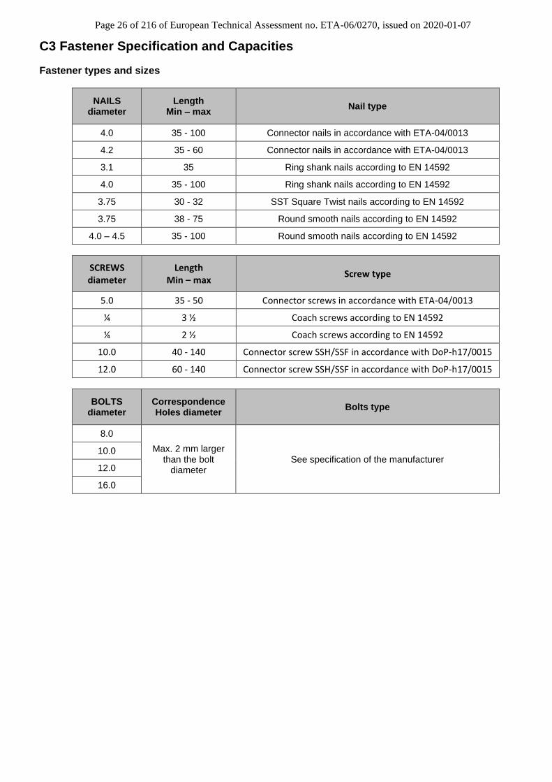
C3 Fastener Specification and Capacities
Fastener types and sizes
NAILS diameter
Length Min – max
Nail type
4.0 35 - 100 Connector nails in accordance with ETA-04/0013
4.2 35 - 60 Connector nails in accordance with ETA-04/0013
3.1 35 Ring shank nails according to EN 14592
4.0 35 - 100 Ring shank nails according to EN 14592
3.75 30 - 32 SST Square Twist nails according to EN 14592
3.75 38 - 75 Round smooth nails according to EN 14592
4.0 – 4.5 35 - 100 Round smooth nails according to EN 14592
SCREWS diameter
Length Min – max
Screw type
5.0 35 - 50 Connector screws in accordance with ETA-04/0013
¼ 3 ½ Coach screws according to EN 14592
¼ 2 ½ Coach screws according to EN 14592
10.0 40 - 140 Connector screw SSH/SSF in accordance with DoP-h17/0015
12.0 60 - 140 Connector screw SSH/SSF in accordance with DoP-h17/0015
BOLTS diameter
Correspondence Holes diameter
Bolts type
8.0
Max. 2 mm larger than the bolt
diameter See specification of the manufacturer
10.0
12.0
16.0
Page 27 of 216 of European Technical Assessment no. ETA-06/0270, issued on 2020-01-07
*ARS: Annular Ring Shank nail **ST: Square Twist nail ***SS: Smooth Shank nail
Typical Hanger Combinations with SSH/SSF
Face Mount Hanger
Face flanges Side flanges
Type Diameter Length
Min - Max Type Diameter
Length Min - Max
GSE,GSE-AL, GLE, GLE-AL, GLI, GLI-AL,
SAE, SAEL, SBE
ARS* 4 35-100 SSH/SSF 10 40 - 140
Screw 5 35-100 SSH/SSF 12 60 - 140
BSNN, SLE ARS* 4 35-100
SSH/SSF 10 50 - 140 Screw 5 35-100
The general model is given here after. It shall be used with the relevant specific form factors kH,1 and kH,2 given
Page 28 of 216 of European Technical Assessment no. ETA-06/0270, issued on 2020-01-07
in Annexe D for each type of face mount hangers The hanger and nail type combinations in the table are typical, but other combinations may also be proven suitable, subject to following the design model in Annex C4 of this document. Capacities of combination with SSH/SSF connector screws are directly given in Annex D for each suitable hanger family.
Page 29 of 216 of European Technical Assessment no. ETA-06/0270, issued on 2020-01-07
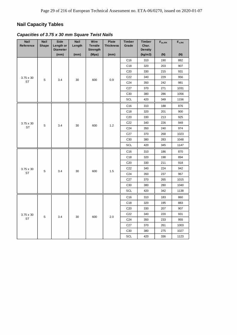
Nail Capacity Tables Capacities of 3.75 x 30 mm Square Twist Nails
Nail
Shape
Side
Length or
Diameter
Nail
Length
Wire
Tensile
Strength
Plate
Thickness
Timber
Grade
Timber
Char.
Density
Fax,RK Fv,RK
(mm) (mm) (Mpa) (mm) (kg/m3) (N) (N)
C16 310 190 882
C18 320 203 907
C20 330 215 931
C22 340 229 956
C24 350 242 981
C27 370 271 1031
C30 380 286 1056
SCL 420 349 1156
C16 310 188 876
C18 320 201 900
C20 330 213 925
C22 340 226 949
C24 350 240 974
C27 370 268 1023
C30 380 283 1048
SCL 420 345 1147
C16 310 186 870
C18 320 198 894
C20 330 211 918
C22 340 224 942
C24 350 237 967
C27 370 265 1015
C30 380 280 1040
SCL 420 342 1138
C16 310 183 860
C18 320 195 883
C20 330 207 907
C22 340 220 931
C24 350 233 955
C27 370 261 1003
C30 380 275 1027
SCL 420 336 1123
Nail
Reference
600 2.03.75 x 30
STS 3.4 30
600 1.5
3.75 x 30
STS
3.75 x 30
STS 3.4 30
3.4 30 600 1.2
600 0.93.75 x 30
STS 3.4 30
Page 30 of 216 of European Technical Assessment no. ETA-06/0270, issued on 2020-01-07
Capacities of 3.75 x 38 mm Round Wire Nails
Nail
Reference
Nail
Shape
Side
Length or
Diameter
Nail
Length
Wire
Tensile
Strength
Plate
Thickness
Timber
Grade
Timber
Char.
Density
Fax,RK Fv,RK
(mm) (mm) (Mpa) (mm) (kg/m3) (N) (N)
C16 310 267 1105
C18 320 285 1139
C20 330 303 1172
C22 340 322 1206
C24 350 341 1240
C27 370 381 1307
C30 380 402 1341
SCL 420 491 1461
C16 310 265 1098
C18 320 283 1131
C20 330 301 1165
C22 340 319 1198
C24 350 338 1231
C27 370 378 1299
C30 380 399 1332
SCL 420 487 1456
C16 310 263 1091
C18 320 280 1124
C20 330 298 1157
C22 340 316 1190
C24 350 335 1223
C27 370 375 1290
C30 380 395 1323
SCL 420 483 1450
C16 310 259 1079
C18 320 276 1111
C20 330 294 1144
C22 340 312 1176
C24 350 331 1209
C27 370 370 1275
C30 380 390 1308
SCL 420 476 1440
3.75 x 38
SSR 3.75 38 600 0.9
600 1.5
3.75 x 38
SSR
3.75 x 38
SSR 3.75 38
3.75 38
600 2.03.75 x 38
SSR 3.75 38
600 1.2
Page 31 of 216 of European Technical Assessment no. ETA-06/0270, issued on 2020-01-07
Capacities of 3.75 x 75 mm Round Wire Nails
Nail
Reference
Nail
Shape
Side
Length or
Diameter
Nail
Length
Wire
Tensile
Strength
Plate
Thickness
Timber
Grade
Timber
Char.
Density
Fax,RK Fv,RK
(mm) (mm) (Mpa) (mm) (kg/m3) (N) (N)
C16 310 534 1309
C18 320 569 1337
C20 330 605 1364
C22 340 642 1392
C24 350 681 1420
C27 370 761 1475
C30 380 803 1502
SCL 420 980 1614
C16 310 532 1309
C18 320 567 1336
C20 330 603 1364
C22 340 640 1391
C24 350 678 1419
C27 370 758 1474
C30 380 799 1502
SCL 420 976 1613
C16 310 530 1308
C18 320 564 1336
C20 330 600 1363
C22 340 637 1391
C24 350 675 1418
C27 370 755 1473
C30 380 796 1501
SCL 420 972 1612
C16 310 526 1307
C18 320 561 1335
C20 330 596 1362
C22 340 633 1390
C24 350 671 1417
C27 370 750 1472
C30 380 791 1499
SCL 420 966 1610
3.75 x 75
SSR 3.75 75 600 0.9
600 1.5
3.75 x 75
SSR
3.75 x 75
SSR 3.75 75
3.75 75
600 2.03.75 x 75
SSR 3.75 75
600 1.2
Capacities of 3.1 x 35 mm Ring Shank Nails according to Eurocode 5 for AG703 installation
Nail reference
Nail shape
Side length or Diameter
(mm)
Nail length (mm)
Wire tensile
Strength (MPa)
Plate thickness
(mm)
Timber Grade
Timber Char.
Density (kg/m3)
Fax,RK (N)
Fv,RK (N)
3.1 x 35 ARS
ARS 3,1 35 600 1,2
C16 310 473 1043
C18 320 473 1069
C20 330 473 1094
C22 340 473 1119
C24 350 473 1145
C27 370 473 1196
C30 380 473 1221
SCL 420 473 1290
Page 32 of 216 of European Technical Assessment no. ETA-06/0270, issued on 2020-01-07
Capacities of SSH/SSF connector screws for plates thickness 1,5 ≤ t ≤ 3 mm
Large connector
screws with plate thickness 1,5 ≤ t ≤ 3 mm
Characteristic shear capacities depending on characteristic density, load perpendicular to grain
320 kg/m3 350 kg/m3 380 kg/m3
Fax,Rk Flat,Rk Fax,Rk Flat,Rk Fax,Rk Flat,Rk
[N] [N] [N] [N] [N] [N]
SSH8.0x40* 2190 2770 2370 2920 2530 3050
SSH8.0x50* 4879 2770 5242 2920 5598 3050
SSH8.0x80* 4879 2770 5242 2920 5598 3050
SSH10.0x40* 2700 3440 2930 3610 3150 3780
SSH10.0x50* 5160 4740 5544 4720 5921 5220
SSH10.0x80* 5160 4740 5544 4720 5921 5220
SSH12.0x60* 5677 6170 6098 6240 6513 6780
SSH12.0x80* 5677 6170 6098 6240 6513 6780
*SSH can be replaced by SSF
These capacities are valid only with the following minimum spacing and edge distances without predrilled holes: Minimum distances [mm]
Spacing parallel to grain
Spacing perpendicular to
grain
Loaded edge
Unloaded edge
Connector screw a1 a2 a2.t a2.c
SSH8.0x40* 40 32 56 40
SSH8.0x50* 40 32 56 40
SSH8.0x80* 40 32 56 40
SSH10.0x40* 60 (40 if a2 ≥ 60) 40 50 40
SSH10.0x50* 60 (40 if a2 ≥ 60) 40 50 40
SSH10.0x80* 60 (40 if a2 ≥ 60) 40 50 40
SSH12.0x60* 40 60 80 40
SSH12.0x80* 40 60 80 40
*SSH can be replaced by SSF Capacities of SSH connector screws for plates 3 ≤ t ≤ 4 mm
Large connector
screws with plate
thickness 3 ≤ t ≤ 4 mm
Characteristic shear capacities depending on characteristic density, load perp. to grain
320 kg/m3 350 kg/m3 380 kg/m3
Fax,Rk Flat,Rk Fax,Rk Flat,Rk Fax,Rk Flat,Rk
[N] [N] [N] [N] [N] [N]
SSH12.0x60* 5677 4750 6098 5030 6513 5620
SSH12.0x80* 5677 4750 6098 5030 6513 5620
*SSH can be replaced by SSF
Page 33 of 216 of European Technical Assessment no. ETA-06/0270, issued on 2020-01-07
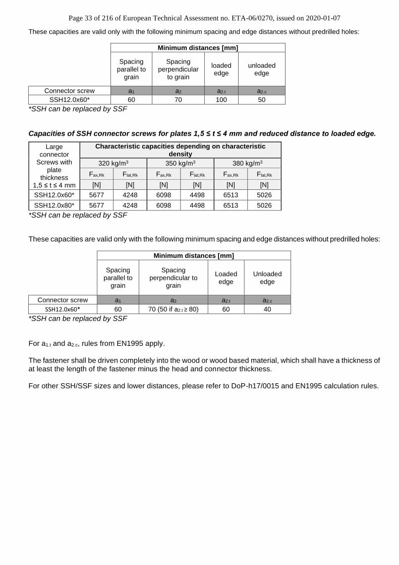
These capacities are valid only with the following minimum spacing and edge distances without predrilled holes: Minimum distances [mm]
Spacing
parallel to grain
Spacing perpendicular
to grain
loaded edge
unloaded edge
Connector screw a1 a2 a2.t a2.c
SSH12.0x60* 60 70 100 50
*SSH can be replaced by SSF
Capacities of SSH connector screws for plates 1,5 ≤ t ≤ 4 mm and reduced distance to loaded edge.
Large connector
Screws with plate
thickness 1,5 ≤ t ≤ 4 mm
Characteristic capacities depending on characteristic density
320 kg/m3 350 kg/m3 380 kg/m3
Fax,Rk Flat,Rk Fax,Rk Flat,Rk Fax,Rk Flat,Rk
[N] [N] [N] [N] [N] [N]
SSH12.0x60* 5677 4248 6098 4498 6513 5026
SSH12.0x80* 5677 4248 6098 4498 6513 5026
*SSH can be replaced by SSF
These capacities are valid only with the following minimum spacing and edge distances without predrilled holes:
Minimum distances [mm]
Spacing
parallel to grain
Spacing perpendicular to
grain
Loaded edge
Unloaded edge
Connector screw a1 a2 a2.t a2.c
SSH12.0x60* 60 70 (50 if a2.t ≥ 80) 60 40
*SSH can be replaced by SSF
For a1.t and a2.c, rules from EN1995 apply. The fastener shall be driven completely into the wood or wood based material, which shall have a thickness of at least the length of the fastener minus the head and connector thickness. For other SSH/SSF sizes and lower distances, please refer to DoP-h17/0015 and EN1995 calculation rules.
Page 34 of 216 of European Technical Assessment no. ETA-06/0270, issued on 2020-01-07
C4 Design Formula where appropriate
Characteristic capacities of the joist hanger connections with nails or screws only. F1 and F2 are assumed to act in the middle of the joist. The lateral force is assumed to act at an distance eJ,F above the centre of gravity of the nails in the joist. The connection is also allowed for connection to column, where the distance between nails perpendicular to grain is minimum 20mm.
Two nails patterns are specified. See ANNEX B
For joist hanger BSN, BSD, BSI, SBG and BSDI the width of the joist shall be at least lpen+2.9d for nails and lpen+4d for CSA screws, where lpen is the penetration length of the nails and d is the diameter of the nails in the joist, for full nailing and partial nailing without staggering the nails in the joist. For partial nailing with staggered nails in the joist the width shall be at least the penetration length of the nails.
Page 35 of 216 of European Technical Assessment no. ETA-06/0270, issued on 2020-01-07
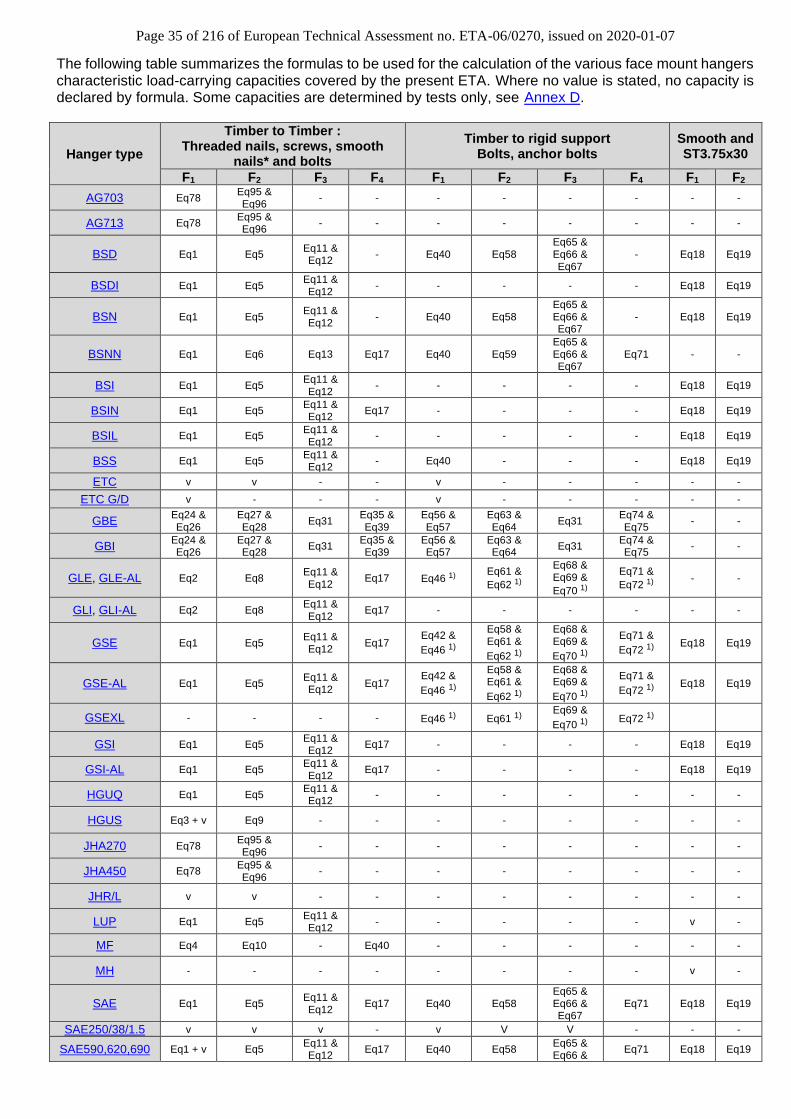
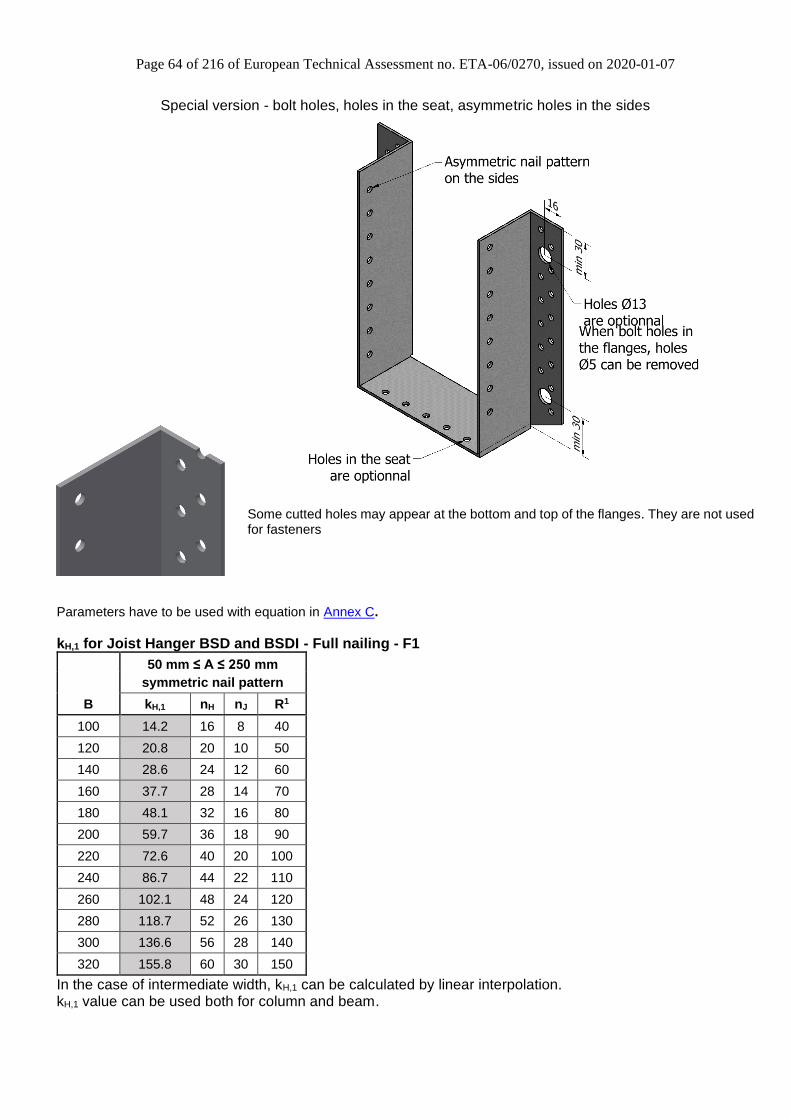
The following table summarizes the formulas to be used for the calculation of the various face mount hangers characteristic load-carrying capacities covered by the present ETA. Where no value is stated, no capacity is declared by formula. Some capacities are determined by tests only, see Annex D.
* Smooth nails should be longer than 75 mm v: Characteristic values given in the product annex 1): These equations can also be used to calculate values for timber to timber application, with bolts -: No value
Page 37 of 216 of European Technical Assessment no. ETA-06/0270, issued on 2020-01-07
C4.1 Joist hangers on timber
C4.1.1 Threaded nails or connector screws This clause covers both the use of threaded nails and screws. C4.1.1.1 F1 load direction:
● For All Joist Hangers except SDED/G, BSN2P, GLE, GLE-AL, GLI, GLI-AL, HGUS and MF
+
+=2
,,1,
2
,,
1,,1,1
11
1;)2(min
kHaxHkHlatH
kJlatJk
RkRn
cRcnR Eq 1.
For GSE, GSI, GSE-AL and GSI-AL : c1 = 0.9 For others: c1 = 1
● For SDED/G, BSN2P, GLE, GLE-AL, GLI and GLI-AL
+
=2
,,1,
2
,,
,,,1
11
1;min
kHaxHkHlatH
kJlatJk
RkRn
RnR Eq 2.
● For HGUS
+
+=2
,,1
2
,,
,,,,90,90,,1
11
1;min
kHaxHkHlatH
kJlatefJJkccfek
RkRn
RknfkCAkR Eq 3.
kJ,ef are given in the following table: Nail type and dimension Reduction factor kJ,ef
Round smooth 3,75 x 75 0,6
Round smooth 4,0 x 90 0,6
ETA annular ring shank 4,0 x 60 according to ETA-04/0013 0,4
● For MF
+
=2
,,1
2
,,
,,,1
11
1;2,4min
kHaxHkHlatH
kJlatk
RkRn
RR Eq 4.
Page 38 of 216 of European Technical Assessment no. ETA-06/0270, issued on 2020-01-07
C4.1.1.2 F2 load direction:
• For the most joist hangers excepted for BSNN, SBG, SLE, SBE, SDED/G, BSN2P, GLE/I, GLE/I-AL, HGUS and MF
+
=2
,,2,
2
,,
2,,2,2
11
1.;.min
kHaxHkHlatH
kJlatJk
RkRn
cRncR Eq 5.
For GSE, GSI, GSE-AL and GSI-AL : c2 = 0.8 For others: c2 = 1
• For BSNN, SBG, SLE and SBE:
−
+
=
h
h
hA
RkRn
RnRe
e
kHaxHkHlatH
kJlatJk
1
7;
11
1;min
2
,,2,
2
,,
,,,2 Eq 6.
With: 7A in N
• For SDED/G, BSN2P
−
+
=
h
h
hA
RkRn
RnRe
e
kHaxHkHlatH
kJlatJk
1
75,014;
11
1;min
2
,,2,
2
,,
,,,2
Eq 7.
• For GLE/I and GLE/I-AL
+
=2
,,2,
2
,,
,,3,2
11
1;min
kHaxHkHlatH
kJlatJk
RkRn
RncR
Eq 8.
With: c3 = 0.9
• For HGUS
+
=2
,,2
2
,,
,,,,2
11
1;min
kHaxHkHlatH
kJlatefJJk
RkRn
RknR Eq 9.
Refer to Eq 3. for values of kJ,ef
Page 39 of 216 of European Technical Assessment no. ETA-06/0270, issued on 2020-01-07
• For MF
+
=2
,,2
2
,,
,,,2
11
1;2,2min
kHaxHkHlatH
kJlatk
RkRn
RR Eq 10.
Page 40 of 216 of European Technical Assessment no. ETA-06/0270, issued on 2020-01-07
C4.1.1.3 F3 load direction: ● For all joist hangers except BSNN, SBG, SLE, SBE and SDED/G: The capacity from the nails in the joist
2
,,
,,
22
,
2
,
,,
,3
2
+
+
=
kJax
kJlatnailJFJ
kJlatJ
k
R
R
A
ee
RnR
Eq 11.
The capacity from the nails in the header
2
,
*
,
2
,
*
,
,,
,3
22
1
+
+
=
Hp
FH
Hp
FH
H
kHlat
k
I
We
I
He
n
RR
Eq 12.
The lateral capacity of the joist hanger is the minor of the capacity of the nails in the joist and the nails in the header.
● For BSNN, SBG, SLE and SBE:
kHlatlat
flp
FHH
kHlatH
k Rk
I
yen
RnR ,,
,
max,
,,
,3
21
½=
+
= Eq 13.
+
=
flp
FHH
Hlat
I
yen
nk
,
max,
212
Eq 14.
F3
eH,F
ymax
Page 41 of 216 of European Technical Assessment no. ETA-06/0270, issued on 2020-01-07
If full nailing of all holes in the header flange is applied a contribution from the nails in the other flange can be added to the value of the above formula. This term is:
kJaxJk RnR ,,,3 ½= Eq 15.
● For SDED/G, BSN2P The capacity of the SDED/G is given by the formula:
( ) 65,0636,1Blank109
22½ 3
,,,,,3
+−+= −
KHaxJKHlatHk RnRnR Eq 16.
Page 42 of 216 of European Technical Assessment no. ETA-06/0270, issued on 2020-01-07
C4.1.1.4 F4 load direction: In some cases, a solicitation of the joist can be applied in the F4 direction. We can estimate the resistant capacity of the joist hanger by Rax.
● For BSNN, BSIN, SAE, SAIX, SAI, SBE, SBG, SLE, GSE, GSE-AL, GSI, GSI-AL, GLE, GLE-AL, GLI and GLI-AL
=
HaxeffH
kJlateffJ
kRn
cRnR
,,
4,,,
,4 min Eq 17.
For BSNN, BSIN, SAE, SAIX, SAI, SBE, SBG, SLE, GLE and GLI c4 = 0.85 For others: c4 = 1 nH,eff the number of nails in the first row close to the bending line
C4.1.2 Square twist nails or smooth round nails C4.1.2.1 F1 Load direction:
kHlatHkJlatefJk RnRnR ,,,,1,,,1 ;min = Eq 18.
Where the following symbols, which have not been defined Annex C0 are: nJ,ef,1 the effective number of nails in the side of the joist
C4.1.2.2 F2 Load direction:
kHlatHkJlatefJk RnRnR ,,,,2,,,2 ;min = Eq 19.
Where the following symbols, which have not been defined in Annex C0 are: nJ,ef,2 the effective number of nails in the side of the joist
C4.1.3 Bolts C4.1.3.1 F1 load direction: ● For GBE and GBI (with bolts in sides and flanges) Fj.k = Fc.90.k + nj Fb.k.j Eq 20.
With: Fc.90.k the capacity of the seat of the joist hanger depending of the timber used.
the eccentricity factor nj the number of bolts in the joist Fb.k.j the lateral capacity of one bolt of the joist (according to EN 1995-1-1) Ftot.j.bear.k = 2 nj
Fbear.j.k
Eq 21.
With: Fbear.j.k the bearing resistance of the steel around the bolt in the joist Fh.k = kb.h nh Fb.k.h Eq 22.
With: kb.h the calibration factor nh the number of bolts in the header Fb.k.h the lateral capacity of one bolt on the header. (according to EN 1995-1-1) Ftot.h.bear.k = 2 nh Fbear.h.k Eq 23.
With: Fbear.h.k the bearing resistance of the steel around the bolt in the header
Page 43 of 216 of European Technical Assessment no. ETA-06/0270, issued on 2020-01-07
The download capacity is defined as the minimum of this four failure mode: R1.k = min( Fj.k , Fh.k , Ftot.h.bear.k , Ftot.j.bear.k) Eq 24.
● For GBE and GBI (with wood screws in sides and bolts in flanges) Fj.screw.k = Fc.90.k + 2 s ns.j Fscrew.k.j Eq 25.
With:
s the eccentricity factor for screws ns.j the number of screws in the joist Fscrew.k.j the lateral capacity of one screw in the joist (according to EN 1995-1-1) R1.k.scr = min ( Fj.screw.k , Fh.k , Ftot.h.bear.k , 2 ns.j Fbear.sc.k) Eq 26. With: Fbear.sc.k the bearing resistance of the steel around the screws on the joist For Fh.k and Ftot.h.bear.k see “For GBE and GBI (with bolts in sides and flanges)” C4.1.3.2 F2 load direction:
• For GBE and GBI (with bolts in sides and flanges) The uplift capacity is defined as the minimum of this four failure mode: R2.k = min ( nj Fb.k.j , Fh.k , Ftot.h.bear.k , Ftot.j.bear.k) Eq 27.
● For GBE and GBI (with wood screws in sides and bolts in flanges) R2.k.scr = min (2 s ns.j Fscrew.k.j , Fh.k , Ftot.h.bear.k , 2 ns.j Fbear.sc.k) Eq 28.
C4.1.3.3 F3 load direction:
• For GBE and GBI (with bolts in sides and flanges) Capacity of the steel around the load application point:
Farea.A= 2 my a / eJH Eq 29.
With: my the moment capacity of the steel a the distance found by test eJH the distance between the header and the bolt in the joist Farea.B = 2 a C F90 Eq 30.
With: C the contact length (=depth of the joist hanger) between the timber and the joist hangers F90 the compressive capacity of the timber joist The lateral capacity is defined as : R3.k = Farea.A + Farea.B Eq 31. ● For GBE and GBI (with wood screws in sides and bolts in flanges) Same as bolted connection.
Page 44 of 216 of European Technical Assessment no. ETA-06/0270, issued on 2020-01-07
C4.1.3.4 F4 load direction:
• For GBE and GBI (with bolts in sides and flanges) Fj.lat.k = nj Fb.lat.k.j Eq 32.
With: nj the number of bolts in the joist Fb.lat.k.j the lateral capacity of the bolt on the joist
Fh.ax.k = nh Fax.h.k Eq 33.
With: nh the number of bolts on each flange of the header Fax.h.k the axial capacity of the bolt on the header
Fk.ax.fl = 2 Mfl /( db.fl - dh/2 ) Eq 34.
With: Mfl the moment capacity of the flange of the joist hangers db.fl the distance between the side of the joist hanger and the bolt in the header dh the diameter of the bolt used on the header Axial capacity is defined as the minimum of the three previous failure mode R4.k = min (Fj.lat.k , Fh.ax.k , Fk.ax.fl) Eq 35.
● For GBE and GBI (with wood screws in sides and bolts in flanges) Fj.lat.k = 2 ns.j Fscrew.k.j Eq 36.
Fh.ax.k = nh Fax.h.k Eq 37.
Fk.ax.fl = 2 Mfl /( db.fl - dh/2 ) Eq 38.
Axial capacity is defined as the minimum of the three previous failure mode
R4.k = min (Fj.lat.k , Fh.ax.k , Fk.ax.fl) Eq 39.
Page 45 of 216 of European Technical Assessment no. ETA-06/0270, issued on 2020-01-07
C4.2 Joist hangers on Rigid support
C4.2.1 General requirement For joist hangers connected to a wall of concrete, lightweight concrete or to a steel member the assumptions for the calculation of the load-carrying capacity of the connection are:
• The Transfer of force from the joist to the joist hanger is as for a wood-wood connection.
• The bolts shall always be positioned symmetrically about the vertical axis of the joist hanger.
• For concrete, the bolts shall use washers recommended with the mechanical anchor delivery by the
suppliers. Check it is a CE marked product with an ETA.
• For bolted application, washer ≥ Ø18 mm shall be installed under the upper bolt heads or nuts.
C4.2.2 Characteristic capacities of a bolted joist hanger connection
C4.2.2.1 F1 load direction
For a F1 load the formulas for the characteristic load-carrying capacity of the joist hanger connection are:
• For all joist hangers except SDED/G, BSN2P, GSE, GSE-AL, GLE and GSEXL
( ) kblatbkjlatjk RnRnR ,,,,,1 ;2min += Eq 40.
For type SBE, SBG and SLE, nb = nef.b
• For SDED/G and BSN2P
kblatbkjlatjk RnRnR ,,,,,1 ,min = for SDED/G Eq 41.
• For GSE and GSE-AL with a blank model from 300 to 500
( ) kbearkjlatjk RRncR ,,,5,1 ;2min += Eq 42.
For GSE and GSE-AL with a blank model from 300 to 500, c5 = 0.9 It must be checked that the combination of lateral and axial forces in the anchor bolt can be carried by these forces. The maximum withdrawal force in a upper bolt can be calculated as follows :
max
1,
2 z
eFF boltax
= Eq 43.
When connected to timber, zmax is reduced by 20 mm.
Page 46 of 216 of European Technical Assessment no. ETA-06/0270, issued on 2020-01-07
The upper two bolts are subjected to a combination of lateral and withdrawal forces. The lateral force is determined assuming an even distribution of the downward force F:
boltboltlat n
FF 1
, = Eq 44.
● This case is for face mount hangers connected to a wall of concrete or to a steel member. ● The bolts shall be positioned symmetrically about the vertical axis of the Face mount hanger. ● The nails in the joists are subjected to a lateral force, which is equally distributed over all nails or screws
in the joist. ● The rotation point can be assumed to be positioned at the top of the bottom plate. ● The forces in the bolts are partly lateral forces, partly withdrawal forces. ● The lateral forces are distributed evenly over all bolts. ● The withdrawal forces are assumed to be taken by the 2 upper bolts with washers (30 x 30 x 3)
The bearing resistance between the bolt and the plate of the face mount hanger is given by the following equation :
pholekuboltkbear tdfnR = ,, Eq 45.
• For GSEXL, GSE and GSE-AL with blank model from 540 to 1020, GLE and GLE-AL In order to calculate value of GSE and GSEXL on concrete we compared 4 failure modes and take the most disadvantageous one.
Where: Fv,StT,Rk is the resistance of the steel to timber connection FAnet,Rk is the resistance of the cross section in tension. Fv,sp,Rk is the resistance of the bolt to steel connection Fanchor,Rk is the resistance of the anchors group / bolts group in case of timber to timber connection To find the design value, kmod and γM must be applied on Fdown,Rk even if the failure is due to a steel failure. Indeed, it will always be on the safe side.
• For a pair of half joist hangers SJH
Eq 47.
On rigid support, the half hangers shall be set symmetrically on the joist. The bearing resistance between the bolt and the plate of the face mount hanger is given by the following equation.
Eq 48.
pholekuboltkbear tdfnR = ,,
It must be checked that the combination of lateral and axial forces in the anchor bolt can be carried by these forces. It can be done with Anchor Designer by applying F1.d (F2.d) and a moment M1.d = F1.d*e (M2.d = F2.d*e) at rotation point at the lower (upper) edge of joist. On the safe side, it can be considered that the maximum withdrawal force on an upper bolt can be calculated according to Eq 45 and Eq 46.
Failure mode: Steel to timber connection The support reaction of the joist causes lateral loading of the fasteners in the joist connection and compression perpendicular to the grain in the contact area between bottom plate and joist. By taking into account the contribution of the bottom plate and the plastic behaviour of the fasteners, the characteristic steel-to-timber load capacity is:
RkcRkfvJRkStTv FFnF ,,,,, += Eq 49.
Where:
Page 47 of 216 of European Technical Assessment no. ETA-06/0270, issued on 2020-01-07
Fv,f,Rk is the characteristic load-carrying capacity of the fasteners in the joist Fc,Rk is the load-carrying capacity of the bottom plate taking into account the compression of the timber perpendicular to the grain and expressed as follows:
kccRkyRkc fkAMF ,90,90,,, 4 = with 4
²..,
,
pku
Rky
tAfM = Eq 50.
For GLE-AL with width > 200 m, the width considered in the calculation is limited to 200 mm
Failure mode: Steel plate Depending on the thickness of the steel plate, the characteristic load capacity Fv,sp,Rk of the bolt-to-steel connection is designed according to EN 1993-1-8 (§3 table 3.4) for the 4 mm hanger and EN 1993-1-3 (§8.3 table 8.4) for the 2.5 mm hanger with the following modifications: The tensile strength FAnet,Rk of the area Anet is calculated assuming a contribution of an effective width which is the actual width + 60 mm for each side of the hanger. According to Eurocode 3, the total effective area is then:
corefnet tdeA +−= )60.2(2 02, Eq 51.
Then, the load bearing capacity of the joist hanger is then:
RkspvRkStTvRkv FFF ,,,,, ;min= Eq 52.
Failure mode: Anchor failure The last failure mode is the failure of anchors/bolts in shear. For this failure mode, it must be checked that the group of anchors/bolts can resist to the load. To check the group anchor, the ETAG001 Annex C must be used. The forces in the anchors/bolts will be partly lateral forces, partly withdrawal forces. The lateral forces are distributed equally over all anchors:
b
Edv
Rklatanchorn
FF
,
,, = Eq 53.
Where: Fv,Ed is downward directed force toward the bottom plate The centre of rotation is assumed at the bottom plate of the joist hanger. For timber to timber connections via bolts, the centre of rotation is 20 mm above the bottom plate. Withdrawal forces are on the safe side assumed to be taken by the 2 upper anchors with washers. The maximum withdrawal force in an upper anchor can be calculated from:
max
,,.2 z
eFF vEd
Rkaxanchor
= Eq 54.
• For GBE and GBI (with bolts in sides and flanges) Fh.anch.k = kb.h nh Flat.anch.d
Eq 55.
With: Flat.anch.d the lateral capacity of the anchor R1.k = min(Fj.k, Fh.anch.k , Ftot.h.bear.k , Ftot.j.bear.k) Eq 56.
For the definition of the different value, see see “F1 load direction: For GBE and GBI (with bolts in sides and flanges)”
• For GBE and GBI (with wood screws in sides and bolts in flanges) R1.k.sc = min( Fj.screw.k , Fh.anch.k , Ftot.h.bear.k , 2ns.jFbear.sc.k) Eq 57.
Page 48 of 216 of European Technical Assessment no. ETA-06/0270, issued on 2020-01-07
C4.2.2.2 F2 Load direction For an F2 Load direction, the formula for the characteristic load-carrying capacity of the joist hanger connection is:
• For all the joist hangers excepted BSNN, SDED/G, BSN2P, SBE, SBG and SLE and GSE (Blank>500), GSE-AL (Blank>500), GLE, GLE-AL and GSEXL
klatboltbkjlatjk RnRnR ,,,,,2 ;min = Eq 58.
• For BSNN, SBG, SBE and SLE
The minimum of following formulas (Eq 37 + Eq 38) If there is no reinforcing for splittering, the following formula is applied:
h
h
hAR
e
eeffk
−
=
1
7,2 Eq 59.
The result of this calculation is in N.
• For SDED/G and BSN2P:
klatboltbefkJlatJk RnRnR ,,,,,,2 ;min = Eq 60.
• For GSE (Blank>500), GSE-AL (Blank>500), GLE, GLE-AL and GSEXL
• For connection with 2 bolts for all joist hangers:
knaillat
nailp
xcenternailJ
J
k R
I
ee
n
R ,,2
,
,,
2,2
32
1
1
+
=
Eq 62.
The force in the anchor bolts are calculated analogous from formula (Eq 27) and (Eq 28).
• For GBE and GBI (with bolts in sides and flanges) R2.k = min( nj Fb.k.j , Fh.anch.k , Ftot.h.bear.k , Ftot.j.bear.k) Eq 63.
• For GBE and GBI (with wood screws in sides and bolts in flanges) R2.k.sc = min(2 s ns.j Fscrew.k.j, Fh.anch.k , Ftot.h.bear.k, 2ns.jFbear.sc.k) Eq 64.
• For a pair of half joist hanger SJH
Eq 65.
On rigid support, the half hangers shall be set symmetrically on the joist. The bearing resistance between the bolt and the plate of the face mount hanger is given by the following equation.
Eq 66.
pholekuboltkbear tdfnR = ,,
Transversal tension in timber shall be checked according to Eq 59.
Page 49 of 216 of European Technical Assessment no. ETA-06/0270, issued on 2020-01-07
C4.2.2.3 F3 load direction
Different formulas are used for joist hangers with 2 or 4 anchor bolts into the supporting structure of for example concrete or steel.
• For all Joist hangers with 2 bolts except GSE, GSE-AL, GLE, GLE-AL and GSEXL
The minimum value of the following formulas and also formula [Eq.6] for the characteristic lateral load-carrying capacity of the joist hanger connection applies to a joist hanger with 2 bolts.
For small eccentricities eH,F:
+
+
−−+
=
2
,,
2
,,
,
2
,,
2
,,
,2
2
,,
2
,,
4
,,
2
,,
2
,,
,,
,3
/12
/1442
kJax
kjlat
FH
kJax
kJlat
FH
J
kJax
klatbolt
kJax
klatbolt
kJax
klatbolt
k
RAR
e
RAR
en
R
R
R
R
R
R
R Eq 67.
For larger eccentricities eH,F:
FH
kJlatJ
ke
RAnR
,
,,
,3
½= Eq 68.
where the symbols previously not defined are:
eH,F is the eccentricity of the lateral force in relation to the centre of the bolts in
each flange. It shall be taken as the numerical value of the eccentricity
Rbolt,lat,k See page 23
Centre line of bolts
eH,F
A
Page 50 of 216 of European Technical Assessment no. ETA-06/0270, issued on 2020-01-07
• For all Joist hangers with 4 bolts except GSE, GSE-AL, GLE, GLE-AL and GSEXL
H,Fe
bolta
a /2 a /2bolt bolt
Centre linie of bolts
For a lateral force the formula for the characteristic load-carrying capacity of the joist hanger connection with 4 Ø10 mm bolts is:
kJaxJ
boltFH
klatboltbolt
k Rnae
RaR ,,
,
,,
,3 21
21
++
= Eq 69.
where the symbols are defined in the previous text, also the limitation on the characteristic lateral capacity of a 10 mm bolt.
• For GSE, GSE-AL and GLE, GLE-AL with 2 bolts
Provided the joist is prevented from rotation around its own axis, i.e. the force is acting right at the anchor bolts with eH,F = 0 mm the characteristic lateral load-carrying capacity of the joist hanger connection with 2 Ø12 mm bolts is:
R3,k = Rbolt,lat,k Eq 70. Where Rbolt,lat,k is the resistance of one anchor in shear
Page 51 of 216 of European Technical Assessment no. ETA-06/0270, issued on 2020-01-07
• For GSE, GSE-AL, GLE, GLE-AL and GSEXL with 4 bolts:
Provided the force is acting between the anchors bolts the characteristic lateral load-carrying capacity of the joist hanger connection with 4 Ø12 mm bolts is:
klatbolt
boltFH
boltk R
ae
aR ,,
,
,3
21+
= Eq 71.
Where: abolt is the distance between the two extreme bolts eH,F is the distance between application load and the centre line of the bolts
• For GSE, GSE-AL, GLE, GLE-AL and GSEXL with 6 and 8 bolts:
Provided the force is acting between the outer anchor bolts and the force is acting eH,F from the middle anchor bolt the characteristic lateral load-carrying capacity of the joist hanger connection with 6 12 mm bolts is:
boltFH
klatbolt
kae
RR
/3
1,
,,
,3+
= (6 bolts)
boltFH
klatbolt
kae
RR
/3
1,
,,
,3+
= ( 8 bolts) Eq 72.
• For GBE and GBI (with bolts in sides and flanges) Same as “F3 load direction: For GBE and GBI (with bolts in sides and flanges)”
• For GBE and GBI (with wood screws in sides and bolts in flanges) Same as “F3 load direction: For GBE and GBI (with bolts in sides and flanges)”
1/4
Page 52 of 216 of European Technical Assessment no. ETA-06/0270, issued on 2020-01-07
C4.2.2.4 F4 load direction
In some cases, a solicitation of the joist can be applied in the F4 direction. We can estimate the resistant capacity of the joist hanger by Rax.
● For BSNN, SAE, SAIX, SBE, SBG, SLE, GSE (2.5mm thick), GSE-AL (2.5 mm thick) and GLE (2.5 mm thick)
=
kN 5.2min
,,
,4
b
kJlatJ
kn
RnR Eq 73.
For the type BSNN, SBE and SBG and SLE: nj = nJ,ef
● GSE (4 mm thick), GSE-AL (4 mm thick), GLE (4 mm thick), GLE-AL (4 mm thick) and GSEXL
=
kN 5.6min
7
,,
,4cn
RnR
b
kJlatJ
k Eq 74.
c7=0.8
It must be checked that the external diameter of the washer is at least twice the diameter of the anchor or the bolt.
• For GBE and GBI (with bolts in sides and flanges) Fh.anch.ax.k = nh Fax.anch.d Eq 75.
• For GBE and GBI (with wood screws in sides and bolts in flanges) R4.k.sc = min(2 ns.j Fscrew.ax.j, Fh.anch.ax.k , Fk.ax.fl) Eq 77.
Page 53 of 216 of European Technical Assessment no. ETA-06/0270, issued on 2020-01-07
C4.3 Load combination
For a combination of forces in the vertical direction and in the lateral direction the following inequalities shall be fulfilled. C4.3.1 – F1 load direction and F3 load direction
0,1
2
,3
,3
2
,1
,1
+
d
d
d
d
R
F
R
F
Eq 78.
C4.3.2 – F2 load direction and F3 load direction
0,1
2
,3
,3
2
,2
,2
+
d
d
d
d
R
F
R
F Eq 79.
C4.3.3 – F1 load direction, F3 load direction and F4 load direction
0,1
2
,4
,4
2
,3
,3
2
,1
,1
+
+
d
d
d
d
d
d
R
F
R
F
R
F Eq 80.
C4.3.4 – F2 load direction, F3 load direction and F4 load direction
0,1
2
,4
,4
2
,3
,3
2
,2
,2
+
+
d
d
d
d
d
d
R
F
R
F
R
F Eq 81.
Factors kH,1 ,kH,2 ,nJ,ef,1 and nJ,ef,2 will be detailed in Annex D for each reference. Effective number of nails nJ,ef,1 and nJ,ef,2 for joist hangers nailed with smooth round nails or square twist nails The effective number of nails nJ,ef,1 and nJ,ef,2 shall be used for calculation of the load-carrying capacity of a wood-wood connection with smooth round nails or square twist nails subjected to a downward force towards the bottom plate, respectively an upward force away from the bottom plate.
Page 54 of 216 of European Technical Assessment no. ETA-06/0270, issued on 2020-01-07
C4.4 Straps hanger on timber
C4.4.1 Basis of Design
The design method detailed below for the JHA, THA, THAI, AG703 and AG713 joist hangers has been validated by calculation assisted by testing method as defined in ETAG 015 and substantiated by BM TRADA Certification as part of the ETA assessment process.
The hanger characteristics needed to apply this method can be found in Annex D.
The designation of symbol is in Annex C0.
C4.4.2 Nail Capacities
The nail capacities are given in Annex C3 and have been validated against hanger test data.
They have had an efficiency factor applied as part of the design method validation and are only for use in conjunction with this ETA and the hangers listed in it.
C4.4.3 Hanger Characteristics
Hanger characteristics are given in Annex C4. For hanger models not included in Annex C4, but within the scope of the ETA, reference should be made to the ETA holder for further information regarding the hanger characteristics.
C4.4.4 F1 load direction
The load is transferred from the supported member (joist) to the supporting member (header) by:
1) Load transfer from the supported member to the hanger
2) Tension in the lower part of the hanger
3) Load transfer from the hanger to the supporting member.
Therefore, the capacity of the system is the minimum of the above three mechanisms:
=
−HeaderHanger
,
Hanger -Joist
1.k
F
F
F
MinR TensionHanger Eq 82.
C4.4.5 Load Transfer from Joist to Hanger (FJoist-Hanger)
The force between joist and hanger per flange (FJoist-Hanger
For uplift force, the load is transferred from the joist into the hanger by the nails in the side of the joist.
For skew nails with a length of 75 mm or greater, the load may also be transferred directly from the joist into the header.
For instances where nails with a length of 30 to 38 mm are inserted perpendicular to the joist the uplift capacity is:
JoistRK,Lat,J2.k Fn6,0F = Eq 99.
When nails with a length of 75 mm are inserted skew to the joist the uplift capacity is:
3
FnF
JoistRK,Lat,
2.k
=
skewnail Eq 100.
Where:
JoistRK,Lat,F is the characteristic lateral capacity of the nails in the joist
C4.4.10 I-beam as headers
If an I-beam is used as a header, a backer block must be installed between the joist hanger and the web. The backer shall fulfill the following criteria:
• The block shall fit tight to the underside of the top flange (Annex B4)
• The surface of the block shall be flush with the side of the flange
• The nails in the backer block shall be of sufficient length so that they go through the web and clinched.
• It is required that the number of nails in the backer block shall be determined from:
( )flangetopwebbacnail nnn 22ker, =
Page 57 of 216 of European Technical Assessment no. ETA-06/0270, issued on 2020-01-07
C4.5 Straps hangers on rigid support
C4.5.1 Basis of Design
The design method detailed below for the THAI1200 joist hangers has been validated by calculation assisted by testing method as defined in ETAG 015.
The hanger characteristics needed to apply this method can be found in Annex D.
The designation of symbol is in Annex C0.
C4.5.2 Nail Capacities
The nail capacities are given in Annex C3 and have been validated against hanger test data.
They have had an efficiency factor applied as part of the design method validation and are only for use in conjunction with this ETA and the hangers listed in it.
C4.5.3 Hanger Characteristics
Hanger characteristics are given in Annex C4.
C4.5.4 F1 load direction – Face fix installation
The load is transferred from the supported member (joist) to the supporting member (header) by:
1) Load transfer from the supported member to the hanger
2) Tension in the lower part of the hanger
3) Load transfer from the hanger to the supporting member.
Therefore, the capacity of the system is the minimum of the above three mechanisms:
Eq 101.
=
−HeaderHanger
,
Hanger -Joist
1.k
F
F
F
MinR TensionHanger
With: Fjois-hanger calculated from Eq83. Fhanger-Tension calculated from Eq86. FHanger-Header checked by the user by checking that the anchor bolts can carry the combination of axial and lateral forces. Maximum withdrawal force in a upper bolt can be calculated as follows:
Eq 102.
The upper two bolts are subjected to a combination of lateral and withdrawal forces. Lateral force is determined assuming an even distribution of the downward force F:
Eq 103.
Page 58 of 216 of European Technical Assessment no. ETA-06/0270, issued on 2020-01-07
ANNEX D PRODUCT DEFINITION AND CAPACITIES
Page 59 of 216 of European Technical Assessment no. ETA-06/0270, issued on 2020-01-07
D1 AG703 Straps hanger
Product Name Material reference acc. to clause II-1
Page 64 of 216 of European Technical Assessment no. ETA-06/0270, issued on 2020-01-07
Special version - bolt holes, holes in the seat, asymmetric holes in the sides
Some cutted holes may appear at the bottom and top of the flanges. They are not used for fasteners
Parameters have to be used with equation in Annex C.
kH,1 for Joist Hanger BSD and BSDI - Full nailing - F1
50 mm ≤ A ≤ 250 mm
symmetric nail pattern
B kH,1 nH nJ R1
100 14.2 16 8 40
120 20.8 20 10 50
140 28.6 24 12 60
160 37.7 28 14 70
180 48.1 32 16 80
200 59.7 36 18 90
220 72.6 40 20 100
240 86.7 44 22 110
260 102.1 48 24 120
280 118.7 52 26 130
300 136.6 56 28 140
320 155.8 60 30 150
In the case of intermediate width, kH,1 can be calculated by linear interpolation. kH,1 value can be used both for column and beam.
Page 65 of 216 of European Technical Assessment no. ETA-06/0270, issued on 2020-01-07
34 mm ≤ A ≤ 250 mm
asymmetric nail pattern
B kH,1 nH nJ R1
100 14.5 4 7 40
120 21.0 6 9 50
140 28.9 8 11 60
160 38.0 10 13 70
180 48.3 12 15 80
200 60.0 14 17 90
220 72.8 16 19 100
240 87.0 18 21 110
260 102.3 20 23 120
280 119.0 22 25 130
300 136.9 24 27 140
320 156.0 26 29 150
In the case of intermediate width, kH,1 can be calculated by linear interpolation. kH,1 value can be used both for column and beam. kH,1 for Joist Hanger BSD and BSDI - Partial nailing - F1
50 mm ≤ A ≤ 250 mm symmetric nail pattern
B kH,1 nH nJ R1
100 9.5 8 4 30
120 12.8 10 6 50
140 17.6 12 6 50
160 22.2 14 8 70
180 28.3 16 8 70
200 34.2 18 10 90
220 41.5 20 10 90
240 48.6 22 12 110
260 57.2 24 12 110
280 65.6 26 14 130
300 75.4 28 14 130
320 85.0 30 16 150
In the case of intermediate width, kH,1 can be calculated by linear interpolation. kH,1 value can be used both for column and beam.
34 mm ≤ A ≤ 250 mm
asymmetric nail pattern
B kH,1 nH nJ R1
100 9.5 8 4 35
120 13.2 10 5 46
140 17.6 12 6 55
160 22.7 14 7 66
180 28.3 16 8 75
200 34.6 18 9 86
220 41.5 20 10 95
Page 66 of 216 of European Technical Assessment no. ETA-06/0270, issued on 2020-01-07
240 49.1 22 11 105
260 57.2 24 12 115
280 66.0 26 13 125
300 75.4 28 14 135
320 85.5 30 15 145
In the case of intermediate width, kH,1 can be calculated by linear interpolation. kH,1 value can be used both for column and beam kH,2 for BSD and BSDI - 34 mm ≤ A ≤ 250 mm - Full or partial nailing - F2
Blank
Total number of nails in the header
kH2
Full nailing Partial nailing Full nailing Partial nailing
BSD A/100 16 8 14,8 7,1
BSD A/120 20 10 21,6 10,4
BSD A/140 24 12 29,6 14,3
BSD A/160 28 14 38,9 18,8
BSD A/180 32 16 49,4 24,0
BSD A/200 36 18 61,2 29,8
BSD A/220 40 20 74,2 36,2
BSD A/240 44 22 88,5 43,3
BSD A/260 48 24 104,0 51,0
BSD A/280 52 26 120,8 59,3
BSD A/300 56 28 138,8 68,2
BSD A/320 60 30 158,1 77,8
kH,2 value can be used both for column and beam
nj,ef,1 and nj,ef,2 for BSD and BSDI - 34 mm≤ A ≤ 250mm - Full or partial nailing - F1 or F2
Blank
Total number of nails F1 F2
in the joist
Full nailing Partial nailing Full nailing Partial nailing Full nailing Partial nailing
nJ,ef,1 nJ,ef,1 nJ,ef,2 nJ,ef,2
BSD A/100 7 4 2,8 0,95 2,69 0,93
BSD A/120 9 5 4,56 3,35 4,3 3,02
BSD A/140 11 6 6,83 4,04 6,29 3,49
BSD A/160 13 7 9,41 6,16 8,48 5,21
BSD A/180 15 8 12,17 6,58 10,79 5,46
BSD A/200 17 9 14,98 9,37 13,13 7,56
BSD A/220 19 10 17,79 9,55 15,47 7,66
BSD A/240 21 11 20,55 12,57 17,8 9,91
BSD A/260 23 12 23,24 12,59 20,1 9,92
BSD A/280 25 13 25,86 15,58 22,37 12,2
BSD A/300 27 14 28,4 15,52 24,62 12,17
BSD A/320 29 15 30,88 18,37 26,84 14,43
Page 67 of 216 of European Technical Assessment no. ETA-06/0270, issued on 2020-01-07
Page 70 of 216 of European Technical Assessment no. ETA-06/0270, issued on 2020-01-07
1st Alternative Blank Form 2nd Alternative Blank Form
Parameters have to be used with equation in Annex C.
kH,1 for Joist Hangers type BSI - Full nailing - F1 See BSN Joist hanger kH,1 for Joist Hangers type BSI – Partial nailing - F1 See BSN Joist hanger kH,2 for BSI - Full or partial nailing - F2
Blank
Total number of nails kH2
in the header
Full nailing Partial nailing Full nailing Partial nailing
1st bla
nk f
orm
380 20 10 25.5 14.6
380 24 12 35 19.7
435 26 14 36.7 20.3
500 30 16 44.9 25
2nd b
lank f
orm
238 8 - 10 -
260 8 - 10 -
320 10 - 12.8 -
380 12 - 17.6 -
435 14 - 20.3 -
500 16 - 25.5 -
Page 71 of 216 of European Technical Assessment no. ETA-06/0270, issued on 2020-01-07
nj,ef,1 and nj,ef,2 for BSI - Full or partial nailing - F1 or F2
Blank
Total number of nails F1 F2
in the joist
Full nailing Partial nailing Full nailing Partial nailing Full nailing Partial nailing
nJ,ef,1 nJ,ef,1 nJ,ef,2 nJ,ef,2
1st bla
nk f
orm
380 10 6 5.45 4.01 5.02 3.47
380 12 6 8.04 5.43 7.19 4.27
435 14 8 9.87 6.47 8.81 5.39
500 16 8 12.58 6.84 11.07 5.6
2nd b
lank f
orm
238 8 - 3.91 - 3.63 -
260 8 - 3.91 - 3.63 -
320 10 - 5.45 - 5.02 -
380 12 - 8.04 - 7.19 -
435 14 - 9.87 - 8.81 -
500 16 - 12.58 - 11.07 -
Page 72 of 216 of European Technical Assessment no. ETA-06/0270, issued on 2020-01-07
D6 BSIN Joist hanger
Product Name
Material reference acc. to clause II-1
Alternative Names
BSIN Steel ref 1 - Steel ref 2 -
Dimensions – Table a Blank sizes for BSIN A/B are equal to A + 2 * B The table below is valid for all BSIN except for the specific sizes listed in Table b.
In the case of intermediate width, kH,1 can be calculated by linear interpolation. kH,1 value can be used both for column and beam. kH,2 for BSNN - Full or partial nailing - F2
Blank
Total number of nails kH2
in the header
Full nailing Partial nailing Full nailing Partial nailing
230 8 6 9.6 6.7
260 12 8 15.9 10.7
320 16 10 25.6 15.7
380 18 12 29.9 21.7
440 22 14 44.3 28.6
500 26 16 58.1 36.4
kH,2 value can be used both for column and beam kH,1 and kH,2 for specific sizes of BSNN
Type
kH,1 kH,2 nH nJ
Full nailing
Partial nailing
Full nailing
Partial nailing
Full nailing
Partial nailing
Full nailing
Partial nailing
BSNN100/100 18 14,4 21,3 13,0 14 8 8 4
BSNN120/110 23 17,3 15,9 10,7 12 8 8 4
BSNN140/120 29,7 19,5 23,9 15,7 16 10 10 6
Page 87 of 216 of European Technical Assessment no. ETA-06/0270, issued on 2020-01-07
Characteristic capacities for BSNN - with connector screw SSH/SSF
Blank
Product capacities - Timber to Timber - Large connector screw
Fasteners Characteristic capacities - Timber C24
Header Joist R1.k R2.k
Qty Type Qty Type 4.0x35 4.0x40 4.0x50 4.0x60 4.0x35 4.0x40 4.0x50 4.0x60
BSNN500 4 SSH10.0x50(1) 16 CNA* 2.13 2.18 2.49 2.84 10.00 10.00 10.00 10.00 (1)SSH can be replaced by SSF
The user shall verify the transversal tension in timber which is not included in these capacities. *Refer to Characteristic Capacities table columns for type of fasteners that can be used on the joist. Capacities vary depending on fastener type used.
Page 88 of 216 of European Technical Assessment no. ETA-06/0270, issued on 2020-01-07
(2) Header and Joist allow full nailing so Header > 147 mm and Joist > 95mm (1) Header and Joist ≥ 97 mm (a) Header and Joist allow full nailing so Header > 195 mm and Joist > 95 mm (b) Header and Joist allow full nailing so Header > 145 mm and Joist > 95 mm (c) Header and Joist allow full nailing so Header ≥ 97 mm and Joist > 95 mm (d) Header and Joist allow full nailing so Header > 200 mm and Joist > 95 mm For uplift value : Fk = min (Hip + Jack ; Max) It has to be checked, that the header has a sufficient stiffness, especially the torsion and the resistance for tension perpendicular to the grain. The width of the header has to fullfill the need. The nails in the hips are placed between 0° and ~ 20° - see picture:
Page 94 of 216 of European Technical Assessment no. ETA-06/0270, issued on 2020-01-07
Nail pattern ETC485R Hangers Single jack and double hips
ETC 502 Hanger Single jack and double hip
25 CNA4,0x35
gap between surface of header
to the end of the joists
10.2
6
38
38
27 CNA4,0x35
10.2
gap between surface of header
to the end of the joists
6
38
38
or 4 bolts M12
header 120x100
header 75x145 (..143)
header 73x195
15 CNA4,0x35
23 CNA4,0x35
3+3 CNA4,0x35
4 CNA4,0x35
3+3 CNA4,0x35
Nailing of the HIP and the JACK
hiphip
jack
a)
b)
c)
header ..x200
d)
30% of load 40% of load 30% of load
3+3 CNA4,0x35
4 CNA4,0x35
3+3 CNA4,0x35
hiphip
jack
40% of load 20% of load 40% of load
Page 95 of 216 of European Technical Assessment no. ETA-06/0270, issued on 2020-01-07
D12 ETC392 Truss Connector
Product Name Material reference acc. to clause II-1
Alternative Names
ETC392 Steel ref 1 - Steel ref 2 -
Dimensions
Model Dimensions [mm]
Holes
Header Supported member
A B C D E F t Qty Size Qty Size
ETC392 38 195 68 54 239 102 2 26 Ø5 20 Ø5
Permitted deviation
- - ±1.0 ±1.0 ±1.0 ±1.0 - - - - -
Characteristic capacity for ETC - Full nailing - F1, F2 - timber to timber - 1 jack + 2 hips
(1) Header and Joist depth ≥ 97 mm (2) Header member can be made of 2 plies 38 x 220 mm. When the header is composed of 2 plies of 38x97 mm, it requires the installation of a 1 ply vertical member (king post) of a minimum width of 97 mm, directly above the header. All joists members shall be installed ensuring a symmetrical configuration. Spacings and edge distances shall be checked for the group of 10 nails located in the upper part of the hanger depending on the header depth and the vertical member dimension.
Page 96 of 216 of European Technical Assessment no. ETA-06/0270, issued on 2020-01-07
The resistance of the supporting and supported members shall be checked, in particular the tension perpendicular to the grain. The nails in the central joist member are installed at approximately 20° - See image below.
Nail pattern ETC392 Nailing of the hips and jack - 1 jack + 2 hips ● Header is made of 2 plys of 38 x 220 mm.
Page 97 of 216 of European Technical Assessment no. ETA-06/0270, issued on 2020-01-07
● Header is made of 2 plys of 38 x 97 mm + a king post of 38 x 97 mm.
Characteristic capacity for ETC - Full nailing - F1, F2 - timber to timber - 1 jack + 1 hip
(1) Header and Joist height ≥ 97 mm (2) Header member can be made of 2 plies 38 x 220 mm. When the header is composed of 2 plies of 38x97 mm, it requires the installation of a 1 ply vertical member (king post) of minimum width of 97 mm, directly above the header. Spacings and edge distances shall be checked for the group of 10 nails located in the upper part of the hanger depending on the header depth and the vertical member dimension. The resistance of the supporting and supported members shall be checked, in particular the tension perpendicular to the grain. The nails in the central joist member are installed at approximately 20° - See image below.
Page 98 of 216 of European Technical Assessment no. ETA-06/0270, issued on 2020-01-07
Nail pattern ETC392 Nailing of the hips and jack - 1 jack + 1 hip ● Header is made of 2 plys of 38 x 220 mm.
Page 99 of 216 of European Technical Assessment no. ETA-06/0270, issued on 2020-01-07
● Header is made of 2 plys of 38 x 97 mm + a king post of 38 x 97 mm.
Characteristic capacity for ETC - Full nailing - F1, F2 - timber to timber - 2 hips
(1) Header and Joist height ≥ 97 mm (2) Header member can be made of 2 plies of 38 x 220 mm. When the header is composed of 2 plies of 38x97
mm, it requires the installation of a 1 ply vertical member (king post) of minimum width of 97 mm, directly above the header. Spacings and edge distances shall be checked for the group of 10 nails located in the upper part of the hanger depending on the header depth and the vertical member dimension. The resistance of the supporting and supported members shall be checked, in particular the tension perpendicular to the grain.
Page 100 of 216 of European Technical Assessment no. ETA-06/0270, issued on 2020-01-07
The nails in the central joist member are installed at approximately 20° - See image below.
Nail pattern ETC392 Nailing of the hips and jack - 2 hips ● Header is made of 2 plys of 38 x 220 mm.
Page 101 of 216 of European Technical Assessment no. ETA-06/0270, issued on 2020-01-07
● Header is made of 2 plys of 38 x 97 mm + a king post of 38 x 97 mm.
Page 102 of 216 of European Technical Assessment no. ETA-06/0270, issued on 2020-01-07
D13 ETC G/D Truss Connector
Product Name Material reference acc. to clause II-1
Options: - Holes for screws are optional - The number and position of holes per flange can vary - Bolts can be in class 4.6 to 10.9
Parameters have to be used with equation in Annex C.
Page 106 of 216 of European Technical Assessment no. ETA-06/0270, issued on 2020-01-07
Parameters for Joist Hanger GBE Standard GBE are as described in the table below :
Blank model
Qty of bolts/flange
Spacing of bolts on the header
Qty of bolts/joist
Spacing of bolts in the joist
Qty of screws in the joist
Spacing of
screws in the joist
γ γs kb.h a
600 2 122.5 2 90 3 48 0.332 0.325 0.70 60
750 2 197.5 2 165 4 48 0.542 0.395 0.70 60
900 3 136 3 120 6 48 0.530 0.516 0.85 60
1050 3 173.5 3 157.5 7 48 0.634 0.567 0.85 60
1200 4 140.5 4 130 9 48 0.646 0.652 0.95 60
1350 4 165.5 4 155 10 48 0.710 0.687 0.95 60
1500 5 143 5 135 12 48 0.726 0.745 0.95 60
For other cases, calculation is made using following parameters :
Qty bolts/flange kb.h
2 0,7
3 0,85
4 0,95
5 0,95
The table below gives values of γ depending of the number of bolts on the joist and the spacing of these bolts.
Qty of bolts in the joist
γ factor depending of the spacing bolt joist [mm]
90 100 120 140 160 180 200 250 300
2 0,33 0,36 0,42 0,48 0,53 0,58 0,62 0,70 0,76
3 0,42 0,46 0,53 0,59 0,64 0,68 0,72 0,79 0,84
4 0,51 0,55 0,62 0,67 0,72 0,76 0,79 0,85 0,89
5 0,58 0,62 0,68 0,74 0,78 0,81 0,84 0,89 0,92
Additional information : - The minimum number of bolts per flange is equal to 2 - The distance of the holes to the top of the flange shall fulfill : 28 mm ≤ at ≤ 50 mm - The distance of the holes to the bottom of the flange shall fulfill : 28 mm ≤ ab ≤ 50 mm - The distance of the holes to the top of the side shall fulfill : 28 mm ≤ bt ≤ 50 mm - The number of bolts on the joist and per flange should be the same - The bolt on the joist must be inserted starting from the lowest and going up - The same number of bolts must be inserted in each flange and positioned symmetrically - Minimum spacing between bolts on the header "as" is equal to 120 mm - Minimum spacing between bolts on the joist "bs" is equal to 60 mm
Page 107 of 216 of European Technical Assessment no. ETA-06/0270, issued on 2020-01-07
D15 GBI Joist hanger
Product Name Material reference acc. to clause II-1
GLE1020/2.5X 8 SSH12.0x60 (1) 41 CNA* 5,5 6,9 7,2 7,5 20,0 20,0 20,0 20,0 (1)SSH can be replaced by SSF
The user shall verify the transversal tension in timber which is not included in these capacities. *Refer to Characteristic capacities table columns for type of fasteners that can be used on the joist. Capacities vary depending on fastener type used.
Page 116 of 216 of European Technical Assessment no. ETA-06/0270, issued on 2020-01-07
Characteristic capacities for GLE/4X - with connector screw SSH/SSF
Blank
Product capacities - Timber to Timber - Large connector screw
Fasteners Characteristic capacities - Timber C24
Header Joist R1.k R2.k
Qty Type Qty Type 4.0x35 4.0x40 4.0x50 4.0x60 4.0x35 4.0x40 4.0x50 4.0x60
GLE1020/4X 8 SSH12.0x60 (1) 41 CNA* 5,1 5,6 5,7 5,9 20,0 20,0 20,0 20,0 (1)SSH can be replaced by SSF
The user shall verify the transversal tension in timber which is not included in these capacities. *Refer to Characteristic capacities table columns for type of fasteners that can be used on the joist. Capacities vary depending on fastener type used. GLE fire resistance R30 to EN 13501-2
See GLE Joist hanger
Page 117 of 216 of European Technical Assessment no. ETA-06/0270, issued on 2020-01-07
GLE1020-AL/2.5X 8 SSH12.0x60(1) 37 CNA* 9,8 9,8 9,8 9,8 20,0 20,0 20,0 20,0 (1)SSH can be replaced by SSF
The user shall verify the transversal tension in timber which is not included in these capacities. *Refer to Characteristic capacities table columns for type of fasteners that can be used on the joist. Capacities vary depending on fastener type used.
Page 124 of 216 of European Technical Assessment no. ETA-06/0270, issued on 2020-01-07
Characteristic capacities for GLE/4X-AL - with connector screw SSH/SSF
Blank
Product capacities - Timber to Timber - Large connector screw
Fasteners Characteristic capacities - Timber C24
Header Joist R1.k R2.k
Qty Type Qty Type 4.0x35 4.0x40 4.0x50 4.0x60 4.0x35 4.0x40 4.0x50 4.0x60
GLE1020-AL/4X 8 SSH12.0x60(1) 37 CNA* 7,8 7,8 7,8 7,8 20,0 20,0 20,0 20,0 (1)SSH can be replaced by SSF
The user shall verify the transversal tension in timber which is not included in these capacities. *Refer to Characteristic capacities table columns for type of fasteners that can be used on the joist. Capacities vary depending on fastener type used. GLE-AL fire resistance R30 to EN 13501-2
See GLE Joist hanger
Page 125 of 216 of European Technical Assessment no. ETA-06/0270, issued on 2020-01-07
D18 GLI Joist hanger
Product Name Material reference acc. to clause II-1
Page 126 of 216 of European Technical Assessment no. ETA-06/0270, issued on 2020-01-07
Parameters have to be used with equation in Annex C.
kH,1 for Joist Hanger GLI - Full nailing - F1 See GLE Joist hanger kH,1 for Joist Hanger GLI - Partial nailing - F1 See GLE Joist hanger kH,2 for GLI - Full or partial nailing - F2 See GLE Joist hanger GLI fire resistance R30 to EN 13501-2 See GLE Joist hanger
Page 127 of 216 of European Technical Assessment no. ETA-06/0270, issued on 2020-01-07
Page 128 of 216 of European Technical Assessment no. ETA-06/0270, issued on 2020-01-07
Parameters have to be used with equation in Annex C.
kH,1 for Joist Hanger GLI-AL - Full nailing - F1 See GLE Joist hanger kH,1 for Joist Hanger GLI-AL - Partial nailing - F1 See GLE Joist hanger kH,2 for GLI-AL - Full or partial nailing - F2 See GLE Joist hanger GLI-AL fire resistance R30 to EN 13501-2 See GLE Joist hanger
Page 129 of 216 of European Technical Assessment no. ETA-06/0270, issued on 2020-01-07
GSE1020 6 SSH12.0x60(1) 40 CNA* 4,9 6,1 6,2 6,4 15,0 15,0 15,0 15,0 (1)SSH can be replaced by SSF The user shall verify the transversal tension in timber which is not included in these capacities. *Refer to Characteristic capacities table columns for type of fasteners that can be used on the joist. Capacities vary depending on fastener type used.
Page 136 of 216 of European Technical Assessment no. ETA-06/0270, issued on 2020-01-07
GSE/GSI 4 mm and GLE/GLI 4 mm fire resistance R30 to EN 13501-2 – timber to timber connection : Performance declared: 30 minutes resistance to Fire (R30) to EN 13501-2 with all faces of the hanger exposed to the fire (Table 3). The performance values were determined by a static model developed by SST validated and verified by testing to EN 1365-2 and ETAG 015 by the Assessment Report BTC 18511FA issued by the Building Test Centre (UKAS accredited No. 0296 and member of the Fire Test Study Group, FTSP). Scope of Certification: This certification applies to the following products and sizes GSE/GSI and GLE/GLI range of 4mm thick (ETA-06/0270).
Service Class: 1 and 2 to Eurocode 5 Fasteners: Fully nailed with CNA4,0x75mm or CSA5.0x80 (ETA-04/0013) Timber: Untreated C24 strength class timber to EN338. The joist was exposed on 3 faces (sides and bottom) and the header on 2 faces (side and bottom). Boundary conditions:
· Header height ≥ Joist height ≥ Hanger height + 10 mm · Joist end shall be within the header face edges · Member width ≥ 100 mm · Gap between members ≤ 3 mm
Any other relevant National minimum requirement shall be fulfilled.
Table 3: Characteristic vertical load bearing capacity R30 to EN 13501-2, Fv,Rk,fi, in kN
Seat Width (mm)
100 120 140 160 180 200
Bla
nk L
en
gth
(m
m)
380 1 1 - - - -
440 2.52 2.52 2.52 2.52 - -
500 3.55 3.55 2.52 2.52 2.52 2.52
540 4.72 4.72 3.55 3.55 3.55 3.55
600 7.3 7.3 5.98 5.98 5.98 5.98
660 8.65 8.65 7.3 7.3 7.3 7.3
720 11.4 11.4 10.03 10.03 10.03 10.03
780 12.76 12.76 11.4 11.4 11.4 11.4
840 15.44 15.44 14.11 14.11 14.11 14.11
900 18.04 18.04 15.44 15.44 15.44 15.44
960 19.32 19.32 16.75 16.75 16.75 16.75
1020 20.57 20.57 19.32 19.32 19.32 19.32
Page 137 of 216 of European Technical Assessment no. ETA-06/0270, issued on 2020-01-07
Simplified calculation of Ed,fi according to Eurocode 5 part 1-2:
GSE 4 mm fire resistance R30 to EN 13501-2 – timber to concrete connection : Performance declared: 30 minutes resistance to Fire (R30) to EN 13501-2 with all faces of the hanger exposed to the fire (Table 3). The performance values were determined by a static model developed by SST validated and verified by testing to EN 1365-2 and ETAG 015 by the Assessment Report BTC 19992FA issued by the Building Test Centre (UKAS accredited No. 0296 and member of the Fire Test Study Group, FTSP). Scope of Certification: This certification applies to the following products and sizes GSE range of 4mm thick (ETA-06/0270) for timber to concrete connection
Table 1: GSE/GSI (4mm thickness) Hanger Height (mm) Table 2: GSE/4 Number of anchors used on each hanger
Seat Width (mm) Seat Width (mm)
100 120 140 160 180 200 100 120 140 160 180 200
Bla
nk L
en
gth
(m
m)
380 140 130 - - - -
Bla
nk L
en
gth
(m
m)
380 2 2 - - - -
440 170 160 - - - - 440 4 4 - - - -
500 200 190 180 170 160 150 500 4 4 2 2 2 2
540 220 210 200 190 180 170 540 4 4 4 4 4 4
600 250 240 230 220 210 200 600 4 4 4 4 4 4
660 280 270 260 250 240 230 660 6 6 4 4 4 4
720 310 300 290 280 270 260 720 6 6 6 6 6 6
780 340 330 320 310 300 290 780 6 6 6 6 6 6
840 370 360 350 340 330 320 840 6 6 6 6 6 6
900 400 390 380 370 360 350 900 6 6 6 6 6 6
960 430 420 410 400 390 380 960 6 6 6 6 6 6
1020 460 450 440 430 420 410 1020 6 6 6 6 6 6
Page 138 of 216 of European Technical Assessment no. ETA-06/0270, issued on 2020-01-07
Service Class: 1 and 2 to Eurocode 5 Fasteners:
- Fixed on concrete C25/30 support with BOAX-II M12-103/5 or equivalent - Fully nailed with CNA4,0x75mm or CSA5.0x80 (ETA-04/0013) on timber
Timber: Untreated C24 strength class timber to EN338. The joist was exposed on 3 faces (sides and bottom). Boundary conditions:
· Header height ≥ Joist height ≥ Hanger height + 10 mm · Joist end shall be within the header face edges · Member width ≥ 100 mm · Gap between members ≤ 3 mm
Any other relevant National minimum requirement shall be fulfilled.
Table 3: Characteristic vertical load bearing capacity R30 to EN 13501-2, Fv,Rk,fi, in kN
Seat Width (mm)
100 120 140 160 180 200
Bla
nk L
en
gth
(m
m)
380 10 10 - - - -
440 20 20 - - - -
500 20 20 10 10 10 10
540 20 20 20 20 20 20
600 20 20 20 20 20 20
660 20.57 20.57 20 20 20 20
720 20.57 20.57 20.57 20.57 20.57 20.57
780 20.57 20.57 20.57 20.57 20.57 20.57
840 20.57 20.57 20.57 20.57 20.57 20.57
900 20.57 20.57 20.57 20.57 20.57 20.57
960 20.57 20.57 20.57 20.57 20.57 20.57
1020 20.57 20.57 20.57 20.57 20.57 20.57
Page 139 of 216 of European Technical Assessment no. ETA-06/0270, issued on 2020-01-07
D21 GSE-AL Joist hanger
Product Name Material reference acc. to clause II-1
GSE1020AL 6 SSH12.0x60(1) 38 CNA* 7,3 7,3 7,3 7,3 15,0 15,0 15,0 15,0 (1)SSH can be replaced by SSF
The user shall verify the transversal tension in timber, which is not included in these capacities. *Refer to Characteristic capacities table columns for type of fasteners that can be used on the joist. Capacities vary depending on fastener type used. GSE-AL fire resistance R30 to EN 13501-2 See GSE Joist hanger
Page 144 of 216 of European Technical Assessment no. ETA-06/0270, issued on 2020-01-07
D22 GSEXL Joist hanger
Product Name Material reference acc. to clause II-1
Characteristic capacity for GSEXL - Full nailing - F1 F2 F3 F4 - timber to rigid support See formulas from Annex C for characteristic values calculation.
Page 145 of 216 of European Technical Assessment no. ETA-06/0270, issued on 2020-01-07
In the case of intermediate width, kH,1 can be calculated by linear interpolation.
Page 163 of 216 of European Technical Assessment no. ETA-06/0270, issued on 2020-01-07
kH,2 for SAE - Full or partial nailing - F2
Blank
Total number of nails in the header
kH2
Full nailing Partial nailing Full nailing Partial nailing
200 8 4 5.6 3
250 12 6 10.3 4.2
300 18 10 19.9 11.4
340 22 12 28.1 15.8
380 22 12 28.1 15.8
440 28 14 42.9 20.4
500 34 18 60.8 32.9
nj,ef,1 and nj,ef,2 for SAE - Full or partial nailing - F1 or F2
Blank
Total number of nails F1 F2
in the joist
Full nailing Partial nailing Full nailing Partial nailing Full nailing Partial nailing
nJ,ef,1 nJ,ef,1 nJ,ef,2 nJ,ef,2
200 5 4 1.29 1.29 1.26 1.24
250 7 4 2.84 2.13 2.69 1.92
300 10 6 6.15 3.9 5.54 3.4
340 12 6 8.76 4.91 7.69 4
380 12 6 8.76 4.91 7.69 4
440 15 8 12.92 7.59 11.06 5.99
500 18 10 17.08 10.69 14.46 8.21
SAE joist hangers are warranted for an installation on timber column. The partial nail pattern that applies then is the one described in Annex B3 for connection to column and above coefficients, valid for partial nailing, apply.
Page 164 of 216 of European Technical Assessment no. ETA-06/0270, issued on 2020-01-07
Characteristic capacity for SAE with Square twist nails - Full nailing - F1 - timber to timber
Model Dimensions1)
Total no. of square twist nails 3,75x30 mm
Characteristic capacity2)
A B nH nJ R1,k
250 50 100 12 7 13.5
250 76 87 12 7 13.5
380 38 171 22 12 22.3
380 45 167.5 22 12 22.3
380 50 165 22 12 22.3
380 64 158 22 12 22.3
380 66 157 22 12 22.3
380 76 152 22 12 22.3
380 90 145 22 12 22.3
380 92 144 22 12 22.3
380 100 140 22 12 22.3
500 38 231 34 18 35
500 46 227 34 18 35
500 50 225 34 18 35
500 64 218 34 18 35
500 66 217 34 18 35
500 76 212 34 18 35
500 91 204.5 34 18 35
500 100 200 34 18 35
500 125 187.5 32 16 28 1) For futher dimensions see the section Dimensions of this annex 2) The characteristic capacity is given for Timber Grade C24 (characteristic density of 350 kg/m3)
Page 165 of 216 of European Technical Assessment no. ETA-06/0270, issued on 2020-01-07
Characteristic capacity for SAE - with connector screw SSH/SSF
References
Product capacities - Timber to Timber - Large connector screw
Fasteners Characteristic capacities - Timber C24
Header Joist R1.k R2.k
Qty Type Qty Type 4.0x35 4.0x40 4.0x50 4.0x60 4.0x35 4.0x40 4.0x50 4.0x60
SAE500 6 SSH12.0x60(1) 18 CNA* 4,5 5,7 6,6 7,2 15,0 15,0 15,0 15,0 (1)SSH can be replaced by SSF
The user shall verify the transversal tension in timber, which is not included in these capacities. *Refer to Characteristic capacities table columns for type of fasteners that can be used on the joist. Capacities vary depending on fastener type used. The capacity is increased for the following configuration:
References
Product capacities - Timber to Timber - Large connector screw
Fasteners Characteristic capacities - Timber C24
Header Joist R1.k R2.k R3.k R4.k
Qty Type Qty Type
SAE200/38/2 2 SSH10.0x40(1) 5 CNA4.0x35 6.23 5.79 2.20 5.00 (1)SSH can be replaced by SSF
Page 166 of 216 of European Technical Assessment no. ETA-06/0270, issued on 2020-01-07
D34 SAE250/38/1,5 Joist hanger
Product Name Material reference acc. to clause II-1
Alternative Names
SAE250/38/1.5 Steel ref 1 - Steel ref 2 -
Dimensions
Blank Dimensions [mm]
Holes
Header Joist
A B C D F t Qty Size Qty Size Qty Size
250 38 106 84 41.5 87 1.5 12 Ø5 2 Ø11 7 Ø5
Permitted deviation
- - ±1.0 ±1.0 ±1.0 - - - - - - -
Characteristic capacity for SAE - Full nailing - Timber to timber
Model Fasteners - CNA4.0x35 Characteristic capacity [kN] - C24
nH nJ R1,k R2,k R3,k
SAE250/38/1.5 12 7 10.8 4.7 6.4
To change the timber density instead of using the kdens factor use in this specific case:
Timber class C14 C16 C18 C20 C22 C24
Factor 0.91 0.93 0.95 0.96 0.98 1.00
Characteristic capacity for SAE - Timber to rigid support
Model
Fasteners Characteristic capacity [kN]
Header Joist
nH Type nJ Type R1,k R2,k R3,k
SAE250/38/1.5 2 M10 7 CNA4.0x35 11.7 5.0 4.4
SAE250/38/1.5* 2 M10 5 CNA4.0x35 11.7 4.3 4.4
*For joist > 95 mm
Page 167 of 216 of European Technical Assessment no. ETA-06/0270, issued on 2020-01-07
The check of the connection with the bolts has to be make as following.
The bolt group (both bolts) has to be as minimum:
a lateral capacity of Fi.d x fbolt.lat** for the bolt on the far side of the force
an axial capacity of Fi.d x fbolt.ax
fbolt.lat fbolt.ax
R1,k 1,00 0,40
R2,k 1,00 1,22
R3,k 1,00** 0,50
Timber elements have to be checked also according to EN 1995, 8.1.4 for direction force F2.
Page 168 of 216 of European Technical Assessment no. ETA-06/0270, issued on 2020-01-07
Page 169 of 216 of European Technical Assessment no. ETA-06/0270, issued on 2020-01-07
Parameters have to be used with equation in Annex C
kH,1 for Joist Hanger SAE590 - SAE620 - SAE690 - Full nailing - F1
590 620 620 690
nH nJ nH nJ nH nJ nH nJ
30 20 40 22 40 22 40 22
A B kH.1 B kH.1 B kH.1 B kH.1
38 - - 291 170.5 - - - -
45 - - 287.5 166.5 - - - -
50 - - 285 163.6 - - - -
64 - - 278 155.6 - - - -
76 - - 272 148.8 - - - -
100 - - 260 135.5 - - - -
125 - - - - 247.5 132.6 - -
150 - - - - 235 119.4 - -
200 195 105 210 85.4 - - - -
201-300 - - - - - - 195 105
kH,2 for SAE590 - SAE620 - SAE690 - Full or partial nailing - F2
Blank
Total number of nails kH2
in the header
Full nailing Partial nailing Full nailing Partial nailing
590 30 16 81.5 40.9
620-a 40 20 105.1 48.9
620-b 40 22 114.7 61.3
690 30 16 81.5 40.9
nj,ef,1 and nj,ef,2 for SAE590 - SAE620 - SAE690 - Full or partial nailing - F1 or F2
Blank
Total number of nails F1 F2
in the joist
Full nailing Partial nailing Full nailing Partial nailing Full nailing Partial nailing
nJ,ef,1 nJ,ef,1 nJ,ef,2 nJ,ef,2
590 20 10 18.46 9.11 15.9 7.42
620-a 22 12 20.67 10.69 17.87 8.9
620-b 22 12 22.35 12 18.92 9.62
690 20 10 18.46 9.11 15.9 7.42
SAE joist hangers are warranted for an installation on timber column. The partial nail pattern that applies then is the one described in Annex B3 for connection to column and above coefficients, valid for partial nailing, apply.
Page 170 of 216 of European Technical Assessment no. ETA-06/0270, issued on 2020-01-07
Characteristic capacity for SAE590 - SAE620 - SAE690 with Square twist nails - Full nailing - F1 - timber to timber
Model Dimensions1)
Total no. of square twist nails 3,75x30 mm
Characteristic capacity2)
A B nH nJ R1,k
590 200 195 30 20 30
620 38 291 40 22 50
620 44 288 40 22 50
620 50 285 40 22 50
620 64 278 40 22 50
620 76 272 40 22 50
620 91 264.5 40 22 50
620 100 260 40 22 50
620 116 252 40 22 50
620 125 247.5 40 22 50
620 150 235 40 22 50
620 195 200-300 30 20 30 1) For further dimensions see the section Dimensions of this annex 2) The characteristic capacity is given for Timber Grade C24 (characteristic density of 350 kg/m3)
Page 171 of 216 of European Technical Assessment no. ETA-06/0270, issued on 2020-01-07
Page 172 of 216 of European Technical Assessment no. ETA-06/0270, issued on 2020-01-07
Parameters have to be used with equation in Annex C
kH,1 for Joist Hanger SAEL - Full nailing - F1 300 340 380 440 500 nH nJ nH nJ nH nJ nH nJ nH nJ
16 8 20 10 20 10 26 13 32 16
A B kH,1 B kH,1 B kH,1 B kH,1 B kH,1
32 134 31.1 154 41.2 174 51.5 204 71.5 234 94.5
34 133 30.6 153 40.7 173 51.0 203 70.9 233 93.8
36 132 30.2 152 40.2 172 50.5 202 70.2 232 93.0
38 131 29.8 151 39.7 171 49.9 201 69.6 231 92.3
40 130 29.4 150 39.2 170 49.4 200 69.0 230 91.5
42 129 29.0 149 38.7 169 48.9 199 68.3 229 90.8
44 128 28.5 148 38.2 168 48.4 198 67.7 228 90.0
46 127 28.1 147 37.7 167 47.9 197 67.0 227 89.3
48 126 27.7 146 37.2 166 47.3 196 66.4 226 88.5
50 125 27.3 145 36.7 165 46.8 195 65.8 225 87.8
52 124 26.9 144 36.2 164 46.3 194 65.1 224 87.0
54 123 26.4 143 35.7 163 45.8 193 64.5 223 86.3
56 122 26.0 142 35.2 162 45.3 192 63.9 222 85.5
58 121 25.6 141 34.7 161 44.8 191 63.2 221 84.8
60 120 25.2 140 34.3 160 44.2 190 62.6 220 84.0
62 119 24.8 139 33.8 159 43.7 189 62.0 219 83.3
64 118 24.4 138 33.3 158 43.2 188 61.4 218 82.6
66 117 24.0 137 32.8 157 42.7 187 60.7 217 81.8
68 116 23.6 136 32.3 156 42.2 186 60.1 216 81.1
70 115 23.2 135 31.9 155 41.7 185 59.5 215 80.4
72 114 22.8 134 31.4 154 41.2 184 58.9 214 79.6
74 113 22.4 133 30.9 153 40.7 183 58.3 213 78.9
76 112 22.0 132 30.4 152 40.2 182 57.6 212 78.2
78 111 21.6 131 30.0 151 39.7 181 57.0 211 77.5
80 110 21.2 130 29.5 150 39.2 180 56.4 210 76.7
82 109 20.8 129 29.0 149 38.7 179 55.8 209 76.0
84 108 20.4 128 28.6 148 38.2 178 55.2 208 75.3
86 107 20.0 127 28.1 147 37.7 177 54.6 207 74.6
88 106 19.6 126 27.7 146 37.2 176 54.0 206 73.9
90 105 19.2 125 27.2 145 36.7 175 53.4 205 73.2
92 104 18.9 124 26.8 144 36.2 174 52.8 204 72.5
94 103 18.5 123 26.3 143 35.7 173 52.2 203 71.7
96 102 18.1 122 25.9 142 35.2 172 51.6 202 71.0
98 101 17.7 121 25.4 141 34.7 171 51.0 201 70.3
100 100 17.4 120 25.0 140 34.3 170 50.4 200 69.6
102 99 17.0 119 24.5 139 33.8 169 49.8 199 68.9
104 98 16.6 118 24.1 138 33.3 168 49.2 198 68.2
106 97 16.3 117 23.7 137 32.8 167 48.6 197 67.5
108 96 15.9 116 23.2 136 32.3 166 48.0 196 66.9
110 95 15.5 115 22.8 135 31.9 165 47.5 195 66.2
112 94 15.2 114 22.4 134 31.4 164 46.9 194 65.5
114 93 14.8 113 22.0 133 30.9 163 46.3 193 64.8
116 92 14.5 112 21.6 132 30.4 162 45.7 192 64.1
118 91 14.2 111 21.1 131 30.0 161 45.1 191 63.4
120 90 13.8 110 20.7 130 29.5 160 44.6 190 62.7
122 - - - - 129 29.0 159 44.0 189 62.1
124 - - - - 128 28.6 158 43.4 188 61.4
126 - - - - 127 28.1 157 42.9 187 60.7
128 - - - - 126 27.7 156 42.3 186 60.1
130 - - - - 125 27.2 155 41.7 185 59.4
132 - - - - 124 26.8 154 41.2 184 58.7
134 - - - - 123 26.3 153 40.6 183 58.1
136 - - - - 122 25.9 152 40.1 182 57.4
138 - - - - 121 25.4 151 39.5 181 56.8
140 - - - - 120 25.0 150 39.0 180 56.1
Page 173 of 216 of European Technical Assessment no. ETA-06/0270, issued on 2020-01-07
142 - - - - 119 24.5 149 38.4 179 55.5
144 - - - - 118 24.1 148 37.9 178 54.8
146 - - - - 117 23.7 147 37.4 177 54.2
148 - - - - 116 23.2 146 36.8 176 53.6
150 - - - - 115 22.8 145 36.3 175 52.9
152 - - - - 114 22.4 144 35.8 174 52.3
154 - - - - 113 22.0 143 35.3 173 51.7
156 - - - - 112 21.6 142 34.7 172 51.0
158 - - - - 111 21.1 141 34.2 171 50.4
160 - - - - 110 20.7 140 33.7 170 49.8
In the case of intermediate width, kH,1 can be calculated by linear interpolation.
Page 174 of 216 of European Technical Assessment no. ETA-06/0270, issued on 2020-01-07
kH,1 for Joist Hanger SAEL - Partial nailing - F1
300 340 380 440 500
nH nJ nH nJ nH nJ nH nJ nH nJ
8 4 10 6 10 6 12 7 16 8
A B kH,1 B kH,1 B kH,1 B kH,1 B kH,1
32 134 18.8 154 24.0 174 29.4 204 38.8 234 55.7
34 133 18.6 153 23.8 173 29.1 203 38.5 233 55.3
36 132 18.3 152 23.5 172 28.8 202 38.2 232 54.9
38 131 18.1 151 23.3 171 28.5 201 37.9 231 54.5
40 130 17.9 150 23.0 170 28.3 200 37.6 230 54.1
42 129 17.6 149 22.8 169 28.0 199 37.3 229 53.7
44 128 17.4 148 22.5 168 27.7 198 37.0 228 53.3
46 127 17.2 147 22.3 167 27.5 197 36.7 227 53.0
48 126 17.0 146 22.0 166 27.2 196 36.4 226 52.6
50 125 16.7 145 21.8 165 26.9 195 36.1 225 52.2
52 124 16.5 144 21.5 164 26.7 194 35.8 224 51.8
54 123 16.3 143 21.3 163 26.4 193 35.5 223 51.5
56 122 16.1 142 21.0 162 26.1 192 35.2 222 51.1
58 121 15.9 141 20.8 161 25.9 191 35.0 221 50.7
60 120 15.6 140 20.5 160 25.6 190 34.7 220 50.3
62 119 15.4 139 20.3 159 25.3 189 34.4 219 50.0
64 118 15.2 138 20.0 158 25.1 188 34.1 218 49.6
66 117 15.0 137 19.8 157 24.8 187 33.8 217 49.2
68 116 14.8 136 19.6 156 24.6 186 33.5 216 48.8
70 115 14.6 135 19.3 155 24.3 185 33.2 215 48.5
72 114 14.3 134 19.1 154 24.0 184 32.9 214 48.1
74 113 14.1 133 18.9 153 23.8 183 32.6 213 47.7
76 112 13.9 132 18.6 152 23.5 182 32.4 212 47.4
78 111 13.7 131 18.4 151 23.3 181 32.1 211 47.0
80 110 13.5 130 18.2 150 23.0 180 31.8 210 46.7
82 109 13.3 129 17.9 149 22.8 179 31.5 209 46.3
84 108 13.1 128 17.7 148 22.5 178 31.2 208 45.9
86 107 12.9 127 17.5 147 22.3 177 30.9 207 45.6
88 106 12.7 126 17.2 146 22.0 176 30.7 206 45.2
90 105 12.5 125 17.0 145 21.8 175 30.4 205 44.9
92 104 12.3 124 16.8 144 21.5 174 30.1 204 44.5
94 103 12.1 123 16.6 143 21.3 173 29.8 203 44.2
96 102 11.9 122 16.4 142 21.0 172 29.6 202 43.8
98 101 11.7 121 16.1 141 20.8 171 29.3 201 43.5
100 100 11.5 120 15.9 140 20.5 170 29.0 200 43.1
102 99 11.3 119 15.7 139 20.3 169 28.8 199 42.8
104 98 11.1 118 15.5 138 20.0 168 28.5 198 42.4
106 97 11.0 117 15.3 137 19.8 167 28.2 197 42.1
108 96 10.8 116 15.1 136 19.6 166 28.0 196 41.7
110 95 10.6 115 14.9 135 19.3 165 27.7 195 41.4
112 94 10.4 114 14.7 134 19.1 164 27.4 194 41.1
114 93 10.3 113 14.5 133 18.9 163 27.2 193 40.7
116 92 10.1 112 14.3 132 18.6 162 26.9 192 40.4
118 91 9.9 111 14.1 131 18.4 161 26.6 191 40.1
120 90 9.7 110 13.9 130 18.2 160 26.4 190 39.7
122 - - - - 129 17.9 159 26.1 189 39.4
124 - - - - 128 17.7 158 25.9 188 39.1
126 - - - - 127 17.5 157 25.6 187 38.7
128 - - - - 126 17.2 156 25.4 186 38.4
130 - - - - 125 17.0 155 25.1 185 38.1
132 - - - - 124 16.8 154 24.9 184 37.8
134 - - - - 123 16.6 153 24.6 183 37.5
136 - - - - 122 16.4 152 24.4 182 37.1
138 - - - - 121 16.1 151 24.2 181 36.8
140 - - - - 120 15.9 150 23.9 180 36.5
Page 175 of 216 of European Technical Assessment no. ETA-06/0270, issued on 2020-01-07
142 - - - - 119 15.7 149 23.7 179 36.2
144 - - - - 118 15.5 148 23.5 178 35.9
146 - - - - 117 15.3 147 23.2 177 35.6
148 - - - - 116 15.1 146 23.0 176 35.3
150 - - - - 115 14.9 145 22.8 175 35.0
152 - - - - 114 14.7 144 22.5 174 34.7
154 - - - - 113 14.5 143 22.3 173 34.4
156 - - - - 112 14.3 142 22.1 172 34.1
158 - - - - 111 14.1 141 21.9 171 33.8
160 - - - - 110 13.9 140 21.7 170 33.5
In the case of intermediate width, kH,1 can be calculated by linear interpolation. kH,2 for SAEL - Full or partial nailing - F2
Blank
Total number of nails kH2
in the header
Full nailing Partial nailing Full nailing Partial nailing
300 16 8 16.4 7.9
340 20 10 23.8 11.4
380 20 10 23.8 11.4
440 26 12 37.6 21.9
500 32 16 54.5 25.9
nj,ef,1 and nj,ef,2 for SAEL - Full or partial nailing - F1 or F2
Blank
Total number of nails F1 F2
in the joist
Full nailing Partial nailing Full nailing Partial nailing Full nailing Partial nailing
nJ,ef,1 nJ,ef,1 nJ,ef,2 nJ,ef,2
300 8 4 3.83 2.59 3.57 2.23
340 10 6 6.15 4.22 5.54 3.61
380 10 6 6.15 4.22 5.54 3.61
440 13 8 10.13 6.45 8.81 5.38
500 16 8 14.31 7.78 12.2 6.08
SAEL joist hangers are warranted for an installation on timber column. The partial nail pattern that applies then is the one described in Annex B3 for connection to column and above coefficients, valid for partial nailing, apply. Characteristic capacity for SAEL with Square twist nails - Full nailing - F1 - timber to timber
Model Dimensions1)
Total no. of square twist nails 3,75x30 mm
Characteristic capacity2)
A B nH nJ R1,k
500 150 175 32 16 28 1 )For futher dimensions see the section Dimensions of this annex 2) The characteristic capacity is given for Timber Grade C24 (characteristic density of 350 kg/m3)
Page 176 of 216 of European Technical Assessment no. ETA-06/0270, issued on 2020-01-07
Characteristic capacity for SAEL - with connector screw SSH/SSF
References
Product capacities - Timber to Timber - Large connector screw
Fasteners Characteristic capacities - Timber C24
Header Joist R1.k R2.k
Qty Type Qty Type 4.0x35 4.0x40 4.0x50 4.0x60 4.0x35 4.0x40 4.0x50 4.0x60
SAEL500 6 SSH12.0x60(1) 16 CNA* 4,3 5,4 6,6 7,2 15,0 15,0 15,0 15,0 (1)SSH can be replaced by SSF The user shall verify the transversal tension in timber, which is not included in these capacities. *Refer to Characteristic capacities table columns for type of fasteners that can be used on the joist. Capacities vary depending on fastener type used.
Page 177 of 216 of European Technical Assessment no. ETA-06/0270, issued on 2020-01-07
In the case of intermediate width, kH,1 can be calculated by linear interpolation. kH,2 for SAI - Full or partial nailing - F2
Blank
Total number of nails kH2
in the header
Full nailing Partial nailing Full nailing Partial nailing
1st B
bla
nk m
odel
200 6 4 3.6 2.5
250 10 4 7.5 2.4
300 15 8 13.5 7.6
340 15 8 13.5 7.6
380 18 10 19.2 12.1
440 23 12 28.2 15
500 28 14 41.3 19.6
2nd
bla
nk
mode
l
200 4 - 2.5 -
250 6 - 4.7 -
Page 181 of 216 of European Technical Assessment no. ETA-06/0270, issued on 2020-01-07
nj,ef,1 and nj,ef,2 for SAI - Full or partial nailing - F1 or F2
Blank
Total number of nails F1 F2
in the joist
Full
nailing Partial nailing
Full nailing
Partial nailing Full
nailing Partial nailing
nJ.ef.1 nJ.ef.1 nJ.ef.2 nJ.ef.2
1st B
lank m
ode
l
200 4 4 1.84 1.84 1.7 1.7
250 6 4 1.91 1.6 1.84 1.51
300 10 6 5.95 3.77 5.39 3.31
340 10 6 5.95 5.69 5.39 4.4
380 12 6 8.5 4.75 7.52 3.92
440 14 8 11.22 7.21 9.74 5.8
500 18 8 16.75 10.46 14.27 8.1
2nd
bla
nk
mode
l
380 4 - 1.84 - 1.7 -
440 6 - 1.91 - 1.84 -
SAI joist hangers are warranted for an installation on timber column. The partial nail pattern that applies then is the one described in Annex B3 for connection to column and above coefficients, valid for partial nailing, apply. Characteristic capacity for SAI with Square twist nails - Full nailing - F1 - timber to timber
Model
Dimensions1) Total no. of square twist nails 3,75x30
mm
Characteristic capacity2)
A B nH nJ R1,k
1st bla
nk M
ode
l 380 90 145 20 12 20.3
380 100 140 20 12 20.3
500 91 204.5 32 18 28
500 100 200 32 18 28
500 125 187.5 32 16 28
500 150 175 32 16 28
1) For further dimensions see the section Dimensions of this annex 2) The characteristic capacity is given for Timber Grade C24 (characteristic density of 350 kg/m3)
Page 182 of 216 of European Technical Assessment no. ETA-06/0270, issued on 2020-01-07
Parameters have to be used with equation in Annex C.
kH,1 for Joist Hanger SAI590 - SAI620 - Full nailing - F1
See SAE590, SAE620 and SAE690 Joist hanger kH,2 for SAI590 - SAI620 - Full or partial nailing - F2 See SAE590, SAE620 and SAE690 Joist hanger nj,ef,1 and nj,ef,2 for SAI590 - SAI620 - Full or partial nailing - F1 or F2 See SAE590, SAE620 and SAE690 Joist hanger SAI joist hangers are warranted for an installation on timber column. The partial nail pattern that applies then is the one described in Annex B3 for connection to column and above coefficients, valid for partial nailing, apply.
Page 183 of 216 of European Technical Assessment no. ETA-06/0270, issued on 2020-01-07
Characteristic capacity for SAI590 - SAI620 with Square twist nails - Full nailing - F1 - timber to timber
Model Dimensions1)
Total no. of square twist nails 3,75x30 mm
Characteristic capacity2)
A B nH nJ R1,k
590 200 195 30 20 30
620 91 264.5 40 22 35
620 100 260 40 22 35
620 116 252 40 22 35
620 125 247.5 40 22 35
620 150 235 40 22 35 1) For futher dimensions see the section Dimensions of this annex 2) The characteristic capacity is given for Timber Grade C24 (characteristic density of 350 kg/m3)
Page 184 of 216 of European Technical Assessment no. ETA-06/0270, issued on 2020-01-07
Page 185 of 216 of European Technical Assessment no. ETA-06/0270, issued on 2020-01-07
Parameters have to be used with equation in Annex C.
kH,1 for Joist Hanger SAIL 1st blank model - Full nailing - F1 300 340 380 440 500
nH nJ nH nJ nH nJ nH nJ nH nJ
16 9 16 10 20 12 26 15 32 18
A B kH,1 B kH,1 B kH,1 B kH,1 B kH,1
80 110 21.2 130 29.5 150 39.2 180 56.4 210 76.7
82 109 20.8 129 29.0 149 38.7 179 55.8 209 76.0
84 108 20.4 128 28.6 148 38.2 178 55.2 208 75.3
86 107 20.0 127 28.1 147 37.7 177 54.6 207 74.6
88 106 19.6 126 27.7 146 37.2 176 54.0 206 73.9
90 105 19.2 125 27.2 145 36.7 175 53.4 205 73.2
92 104 18.9 124 26.8 144 36.2 174 52.8 204 72.5
94 103 18.5 123 26.3 143 35.7 173 52.2 203 71.7
96 102 18.1 122 25.9 142 35.2 172 51.6 202 71.0
98 101 17.7 121 25.4 141 34.7 171 51.0 201 70.3
100 100 17.4 120 25.0 140 34.3 170 50.4 200 69.6
102 99 17.0 119 24.5 139 33.8 169 49.8 199 68.9
104 98 16.6 118 24.1 138 33.3 168 49.2 198 68.2
106 97 16.3 117 23.7 137 32.8 167 48.6 197 67.5
108 96 15.9 116 23.2 136 32.3 166 48.0 196 66.9
110 95 15.5 115 22.8 135 31.9 165 47.5 195 66.2
112 94 15,2 114 22,4 134 31.4 164 46.9 194 65.5
114 93 14,8 113 22,0 133 30.9 163 46.3 193 64.8
116 92 14,5 112 21,6 132 30.4 162 45.7 192 64.1
118 91 14,2 111 21,1 131 30.0 161 45.1 191 63.4
120 90 13,8 110 20,7 130 29.5 160 44.6 190 62.7
122 - - - - 129 29.0 159 44.0 189 62.1
124 - - - - 128 28.6 158 43.4 188 61.4
126 - - - - 127 28.1 157 42.9 187 60.7
128 - - - - 126 27.7 156 42.3 186 60.1
130 - - - - 125 27.2 155 41.7 185 59.4
132 - - - - 124 26.8 154 41.2 184 58.7
134 - - - - 123 26.3 153 40.6 183 58.1
136 - - - - 122 25.9 152 40.1 182 57.4
138 - - - - 121 25.4 151 39.5 181 56.8
140 - - - - 120 25.0 150 39.0 180 56.1
142 - - - - 119 24.5 149 38.4 179 55.5
144 - - - - 118 24.1 148 37.9 178 54.8
146 - - - - 117 23.7 147 37.4 177 54.2
148 - - - - 116 23.2 146 36.8 176 53.6
150 - - - - 115 22.8 145 36.3 175 52.9
152 - - - - 114 22.4 144 35.8 174 52.3
154 - - - - 113 22.0 143 35.3 173 51.7
156 - - - - 112 21.6 142 34.7 172 51.0
158 - - - - 111 21.1 141 34.2 171 50.4
160 - - - - 110 20.7 140 33.7 170 49.8
In the case of intermediate width, kH,1 can be calculated by linear interpolation.
Page 186 of 216 of European Technical Assessment no. ETA-06/0270, issued on 2020-01-07
kH,1 for Joist Hanger SAIL 1st blank model - Partial nailing - F1 300 340 380 440 500
nH nJ nH nJ nH nJ nH nJ nH nJ
8 4 10 6 10 6 12 7 16 8
A B kH,1 B kH,1 B kH,1 B kH,1 B kH,1
80 110 13.0 130 17.6 150 22.4 180 31.8 210 46.7
82 109 12.8 129 17.4 149 22.1 179 31.5 209 46.3
84 108 12.6 128 17.1 148 21.9 178 31.2 208 45.9
86 107 12.4 127 16.9 147 21.6 177 30.9 207 45.6
88 106 12.2 126 16.7 146 21.4 176 30.7 206 45.2
90 105 12.0 125 16.5 145 21.1 175 30.4 205 44.9
92 104 11.8 124 16.3 144 20.9 174 30.1 204 44.5
94 103 11.6 123 16.0 143 20.6 173 29.8 203 44.2
96 102 11.4 122 15.8 142 20.4 172 29.6 202 43.8
98 101 11.2 121 15.6 141 20.2 171 29.3 201 43.5
100 100 11.1 120 15.4 140 19.9 170 29.0 200 43.1
102 99 10.9 119 15.2 139 19.7 169 28.8 199 42.8
104 98 10.7 118 15.0 138 19.4 168 28.5 198 42.4
106 97 10.5 117 14.8 137 19.2 167 28.2 197 42.1
108 96 10.3 116 14.6 136 19.0 166 28.0 196 41.7
110 95 10.2 115 14.4 135 18.7 165 27.7 195 41.4
112 - - - - 134 18.5 164 27.4 194 41.1
114 - - - - 133 18.3 163 27.2 193 40.7
116 - - - - 132 18.0 162 26.9 192 40.4
118 - - - - 131 17.8 161 26.6 191 40.1
120 - - - - 130 17.6 160 26.4 190 39.7
122 - - - - 129 17.4 159 26.1 189 39.4
124 - - - - 128 17.1 158 25.9 188 39.1
126 - - - - 127 16.9 157 25.6 187 38.7
128 - - - - 126 16.7 156 25.4 186 38.4
130 - - - - 125 16.5 155 25.1 185 38.1
132 - - - - 124 16.3 154 24.9 184 37.8
134 - - - - 123 16.0 153 24.6 183 37.5
136 - - - - 122 15.8 152 24.4 182 37.1
138 - - - - 121 15.6 151 24.2 181 36.8
140 - - - - 120 15.4 150 23.9 180 36.5
142 - - - - 119 15.2 149 23.7 179 36.2
144 - - - - 118 15.0 148 23.5 178 35.9
146 - - - - 117 14.8 147 23.2 177 35.6
148 - - - - 116 14.6 146 23.0 176 35.3
150 - - - - 115 14.4 145 22.8 175 35.0
152 - - - - 114 14.2 144 22.5 174 34.7
154 - - - - 113 14.0 143 22.3 173 34.4
156 - - - - 112 13.8 142 22.1 172 34.1
158 - - - - 111 13.6 141 21.9 171 33.8
160 - - - - 110 13.5 140 21.7 170 33.5
In the case of intermediate width, kH,1 can be calculated by linear interpolation.
Page 187 of 216 of European Technical Assessment no. ETA-06/0270, issued on 2020-01-07
kH,1 for Joist Hanger SAIL 2nd blank model - Full nailing - F1
300 340 380 440 500
nH nJ nH nJ nH nJ nH nJ nH nJ
8 8 10 10 10 10 12 13 16 16
A B kH,1 B kH,1 B kH,1 B kH,1 B kH,1
38 131 16,6 151 21,8 171 27,1 201 36,6 231 49,1
40 130 16,4 150 21,6 170 26,8 200 36,2 230 48,7
42 129 16,2 149 21,3 169 26,5 199 35,9 229 48,3
44 128 15,9 148 21,1 168 26,3 198 35,6 228 47,9
46 127 15,7 147 20,8 167 26,0 197 35,3 227 47,6
48 126 15,5 146 20,5 166 25,7 196 35,0 226 47,2
50 125 15,3 145 20,3 165 25,5 195 34,7 225 46,8
52 124 15,1 144 20,0 164 25,2 194 34,4 224 46,4
54 123 14,9 143 19,8 163 25,0 193 34,1 223 46,0
56 122 14,7 142 19,5 162 24,7 192 33,8 222 45,7
58 121 14,4 141 19,3 161 24,4 191 33,5 221 45,3
60 120 14,2 140 19,0 160 24,2 190 33,2 220 44,9
62 119 14,0 139 18,8 159 23,9 189 32,9 219 44,5
64 118 13,8 138 18,5 158 23,6 188 32,6 218 44,1
66 117 13,6 137 18,3 157 23,4 187 32,3 217 43,8
68 116 13,4 136 18,0 156 23,1 186 32,0 216 43,4
70 115 13,2 135 17,8 155 22,9 185 31,7 215 43,0
72 114 13,0 134 17,5 154 22,6 184 31,4 214 42,6
74 113 12,8 133 17,3 153 22,3 183 31,1 213 42,3
76 112 12,5 132 17,0 152 22,1 182 30,8 212 41,9
78 111 12,3 131 16,8 151 21,8 181 30,5 211 41,5
Page 188 of 216 of European Technical Assessment no. ETA-06/0270, issued on 2020-01-07
kH,2 for SAIL - Full or partial nailing - F2
Blank
Total number of nails kH2
in the header
Full nailing Partial nailing Full nailing Partial nailing
1st b
lank m
od
el 300 16 8 16.4 7.9
340 20 10 23.8 11.4
380 20 10 23.8 11.4
440 26 14 37.6 21.9
500 32 16 54.5 25.9
2nd b
lank m
od
el 300 8 - 7.8 -
340 10 - 11.4 -
380 10 - 11.4 -
440 12 - 15.8 -
500 16 - 26.5 -
nj,ef,1 and nj,ef,2 for SAIL - Full or partial nailing - F1 or F2
Blank
Total number of nails F1 F2
in the joist
Full
nailing Partial nailing
Full nailing
Partial nailing Full
nailing Partial nailing
nJ,ef,1 nJ,ef,1 nJ,ef,2 nJ,ef,2
1st bla
nk m
ode
l 300 8 4 3.83 2.59 3.57 2.23
340 10 6 6.15 4.22 5.54 3.61
380 10 6 6.15 4.22 5.54 3.61
440 13 8 10.13 6.45 8.81 5.38
500 16 8 14.31 7.78 12.2 6.08
2nd b
lank m
od
el 300 10 - 6.15 - 5.54 -
340 10 - 6.15 - 5.54 -
380 12 - 8.76 - 7.69 -
440 14 - 11.52 - 9.93 -
500 18 - 17.08 - 14.46 -
SAIL joist hangers are warranted for an installation on timber column. The partial nail pattern that applies then is the one described in Annex B3 for connection to column and above coefficients, valid for partial nailing, apply.
Page 189 of 216 of European Technical Assessment no. ETA-06/0270, issued on 2020-01-07
D40 SAIX Joist hanger
Product Name
Material reference acc. to clause II-1
Alternative Names
SAIX Steel ref 2
or S250GD + ZM310 SAEX (external flanges) SAIX (internal flanges)
In the case of intermediate width, kH,1 can be calculated by linear interpolation. kH,1 for Joist Hanger SAIX - Partial nailing - F1 For 1st blank model - See SAE Joist hanger
Page 192 of 216 of European Technical Assessment no. ETA-06/0270, issued on 2020-01-07
For 2nd blank model
380 440 500
nH nJ nH nJ nH nJ
22 12 28 15 34 18
A B kH,1 B kH,1 B kH,1
80 150 23.8 180 32.7 210 47.8
82 149 23.5 179 32.3 209 47.4
84 148 23.2 178 32.0 208 47.0
86 147 22.9 177 31.6 207 46.5
88 146 22.6 176 31.3 206 46.1
90 145 22.3 175 30.9 205 45.7
92 144 22.0 174
30.6 204 45.2
94 143 21.7 173 30.3 203 44.8
96 142 21.4 172 29.9 202 44.4
98 141 21.1 171 29.6 201 43.9
100 140 20.8 170 29.3 200 43.5
102 139 20.5 169 28.9 199 43.1
104 138 20.2 168 28.6 198 42.7
106 137 19.9 167 28.3 197 42.2
108 136 19.6 166 27.9 196 41.8
110 135 19.3 165 27.6 195 41.4
112 134 19.1 164 27.3 194 41.0
114 133 18.8 163 26.9 193 40.5
116 132 18.5 162 26.6 192 40.1
118 131 18.2 161 26.3 191 39.7
120 130 17.9 160 26.0 190 39.3
For 3rd Blank model - No partial nailing capacities kH,2 for SAIX - Full or partial nailing - F2
Blank
Total number of nails kH2
in the header
Full nailing Partial nailing Full nailing Partial nailing
1st b
lank m
od
el
250
See SAE Joist hanger
300
340
380
440
500
2nd b
lank
mode
l 380 22 12 27.4 15.4
440 28 14 41.8 19.9
500 34 18 59.3 32.1
3rd
bla
nk m
od
el
250 6 - 4.7 -
300 10 - 11.1 -
340 12 - 15.4 -
380 12 - 15.4 -
440 14 - 20.3 -
500 18 - 32.1 -
Page 193 of 216 of European Technical Assessment no. ETA-06/0270, issued on 2020-01-07
nj,ef,1 and nj,ef,2 for SAIX - Full or partial nailing - F1 or F2
Blank
Total number of nails F1 F2
in the joist
Full
nailing Partial nailing
Full nailing
Partial nailing Full
nailing Partial nailing
nJ,ef,1 nJ,ef,1 nJ,ef,2 nJ,ef,2
1st b
lank m
od
el
250
See SAE Joist hanger
300
340
380
440
500
2nd b
lank
mode
l 380 12 6 8.76 4.91 7.69 4.00
440 15 8 12.92 7.59 11.06 5.99
500 18 10 17.08 10.69 14.46 8.21
3rd
bla
nk m
od
el
250 7 4 2.84 2.13 2.69 1.92
300 9 6 4.94 3.51 4.52 3.13
340 11 6 7.43 5.12 6.6 4.12
380 11 6 7.43 4.56 6.6 3.81
440 15 8 12.92 7.96 11.06 6.16
500 18 10 17.08 10.69 14.46 8.21
SAIX joist hangers are warranted for an installation on timber column. The partial nail pattern that applies then is the one described in Annex B3 for connection to column and above coefficients, valid for partial nailing, apply.
Page 194 of 216 of European Technical Assessment no. ETA-06/0270, issued on 2020-01-07
D41 SAMI/4X Joist hanger
Product Name Material reference acc. to clause II-1
Alternative Names
SAMI/4X Steel ref 1 - Steel ref 2 -
Dimensions
Blank Dimensions [mm]
Holes
Joist Header
A B C D t Qty Size Qty Size
SAMI/4X 76-150 116 121 310 4 10 Ø5x12 4 Ø12
Permitted deviation
- - ±1.0 ±1.0 - - - - -
Characteristic capacity for SAMI/4X - F1 - timber to timber
Model Fasteners
Characteristic capacity [kN] - C24
nH nJ R1,k
SAMI/4X 4 Ø10 10 CNA4.0x35 31.3
Page 195 of 216 of European Technical Assessment no. ETA-06/0270, issued on 2020-01-07
SBE500 4 SSH10.0x50(1) 16 CNA* 2,0 2,2 2,5 2,8 10,0 10,0 10,0 10,0 (1)SSH can be replaced by SSF
The user shall verify the transversal tension in timber, which is not included in these capacities. *Refer to Characteristic Capacities table columns for type of fasteners that can be used on the joist. Capacities vary depending on fastener type used.
Page 200 of 216 of European Technical Assessment no. ETA-06/0270, issued on 2020-01-07
D43 SBE45/168/TF Joist hanger
Product Name Material reference acc. to clause II-1
In the case of intermediate width, kH,1 can be calculated by linear interpolation. For SBG: when t-t2 < 4 x d, don’t use the holes in the joist, they are opposed. Then, the number of nails in the joist needs to be reduced in accordance with Eurocode 5, clause 8.3.1.1 (7) kH,1 value can be used both for column and beam
Page 203 of 216 of European Technical Assessment no. ETA-06/0270, issued on 2020-01-07
kH,1 for Joist Hanger SBG-SLE - Partial nailing - F1
In the case of intermediate width, kH,1 can be calculated by linear interpolation. For SBG: when t-t2 < 4 x d, don’t use the holes in the joist, they are opposed. Then, the number of nails in the joist needs to be reduced in accordance with Eurocode 5, clause 8.3.1.1 (7) kH,1 value can be used both for column and beam kH,2 for SBG-SLE - Full or partial nailing - F2
Blank
Total number of nails kH2
in the header
Full nailing Partial nailing Full nailing Partial nailing
230 8 6 9.6 6.7
260 12 8 15.9 10.7
320 16 10 25.6 15.7
380 18 12 29.9 21.7
440 22 14 44.3 28.6
500 26 16 58.1 36.4
kH,2 value can be used both for column and beam
Page 204 of 216 of European Technical Assessment no. ETA-06/0270, issued on 2020-01-07
D45 SDED/G and BNS2P Joist hanger
Product Name Material reference acc. to clause II-1
Alternative Names
SDED/G Steel ref 1 - Steel ref 2 -
BSN2P Steel ref 1 - Steel ref 2 -
Dimensions
Blank Dimensions [mm]
Holes
Header Joist
A B C D F t Qty Size Qty Size Qty Size
SDED/G
300 60-250 118 84 41.5 86 2 2 x 9 Ø5 2 x 2 Ø13 2 x 5 Ø5
340 60-250 138 84 41.5 86 2 2 x 11 Ø5 2 x 2 Ø13 2 x 6 Ø5
380 60-250 158 84 41.5 86 2 2 x 11 Ø5 2 x 2 Ø13 2 x 6 Ø5
440 60-250 188 84 41.5 86 2 2 x 14 Ø5 2 x 2 Ø13 2 x 7 Ø5
BSN2P
BSN2P30/98 60-200 98 70.5 39.5 72.5 2 2 x 8 Ø5 2 x 2 Ø9 2 x 4 Ø5
BSN2P30/152 60-250 152 78 42 80 2 2 x 12 Ø5 2 x 2 Ø11 2 x 12 Ø5
BSN2P30/180 60-250 180 85 44 87 2 2 x 13 Ø5 2 x 3 Ø11 2 x 7 Ø5
Permitted deviation
- - ±1.0 ±1.0 ±1.0 - - - - - - -
Parameters have to be used with equation in Annex C.
kH,1 and kH,2 – SDED/G BSN2P - Full Nailing
Blank
Coefficients
kH,1 kH,2
SDED/G
300 24 19.9
340 32.9 28.1
380 38.6 28.1
440 55.9 42.9
BSN2P
BSN2P30/98 17.7 16.6
BSN2P30/152 51.7 32.8
BSN2P30/180 73.4 37.6
Page 205 of 216 of European Technical Assessment no. ETA-06/0270, issued on 2020-01-07
D46 SHT Strap hanger
Product Name Material reference acc. to clause II-1
Alternative Names
SHT Steel ref 1 - Steel ref 2 -
Dimensions
Reference Dimensions [mm]
Holes
Header Joist
A B C D E F t Qty Size Qty Size
SHT115/38 38 90 83.5 35.9 115 85 1.5 12 Ø5 6 Ø5
Permitted deviation - - - - - - - - - - -
Characteristic Capacities for SHT - Timber to Timber – C24
Hanger Type
Installation Configuration
Fasteners - CNA 4.0 x 35 Characteristic capacity
[kN] - C24 Supporting Timber Fasteners
Supported Timber
Fasteners Top Face R1,k R2,k
SHT115/38 Face Fix - 12 6 9.60 6.69
SHT115/38 Wrap Over 2 8 6 9.40 5.82
Page 206 of 216 of European Technical Assessment no. ETA-06/0270, issued on 2020-01-07
D47 SJH Joist hanger
Dimensions
Model
Dimensions [mm] Holes
A B C D t Header Joist
Qty Size Qty Size Qty Size
SJH80 35.8 80 60 41.6 2 4 Ø5 1 Ø11 3 Ø5
SJH130 35.8 130 60 41.6 2 9 Ø5 2 Ø13 5 Ø5
SJH170 35.8 170 60 41.6 2 13 Ø5 2 Ø13 7 Ø5
Joist dimensions
Model
Joist dimensions with one pair of SJH [mm]
Width* Height
Min. Max. Min. Max. Max+**
SJH170 35 90 97 145 220
SJH80 35 140 147 225 300
SJH130 35 160 187 300 0
* When CNA4.0x50 or CSA5.0x50 is used, min joist width is 50 mm ** Reinforcement of joist with full threaded screw type ESCRFTZ required (recommended: 8.0x140 for SJH80, 8.0x220 for SJH130, 8.0x300 for SJH170)
Characteristic capacities – Timber to timber C24 Characteristic capacities per pair of half hangers - Timber to timber - C24 [kN] Header Joist R1.k = R2.k
Model nH nJ CNA4.0x35 CNA4.0x50 CSA5.0x35 CSA5.0x50
SJH80 8 6 5.45 7.84 9.53 10.88
SJH130 18 10 15.95 22.76 25.31 28.76
SJH170 26 14 28.35 39.84 41.23 46.75
Page 207 of 216 of European Technical Assessment no. ETA-06/0270, issued on 2020-01-07
Characteristic capacities per pair of half hanger - Timber to timber - C24 [kN]
The capacities are valid for a pair of half hangers, which can be set on the joist symmetrically or on opposed corners, except for R3.k*** which is only valid if half joist hangers are set on opposed corners (diagonally). For two pairs of hangers used on the same joist end, capacities can be multiplied by 2.
Page 208 of 216 of European Technical Assessment no. ETA-06/0270, issued on 2020-01-07
D48 TFU Joist hanger
Product Name Material reference acc. to clause II-1
Page 209 of 216 of European Technical Assessment no. ETA-06/0270, issued on 2020-01-07
Characteristic capacity for TFU - Timber to Timber - C24
Model Fasteners R1.k and R2.k [kN] R3.k [kN]
nH nJ CNA4,0x35 CNA4,0x40 CNA4,0x50 CNA4,0x60 All nails
TFU A/100 (96) 6 6 3.4 3.9 4.8 5.6 6.31 / kmod
TFU A/120 8 8 5.6 6.4 8 9.2 7.64 / kmod
TFU A/141 10 10 8.3 9.4 11.8 13.5 8.97 / kmod
TFU A/158 12 12 11.3 12.8 16 18.2 10.29 / kmod
TFU A/181 14 14 14.7 16.6 20.7 23.4 11.62 / kmod
TFU A/198 16 16 18.3 20.6 25.6 28.8 12.95 / kmod
TFU A/221 18 18 22 24.8 30.7 34.4 14.28 / kmod
TFU A/238 20 20 25.9 29.1 35.9 40.1 15.61 / kmod
TFU A/261 22 22 29.9 33.5 41.3 45.8 16.94 / kmod
TFU A/278 24 24 33.9 37.9 46.6 51.6 18.26 / kmod
TFU A/300 26 26 38 42.4 52 57.3 19.59 / kmod
Only the nails with a distance to the border according to EN1995-1 can be considered
> 25
> 25
> 25
> 25
> 25
top nail
top nail
Page 210 of 216 of European Technical Assessment no. ETA-06/0270, issued on 2020-01-07
Characteristic capacity for TFU - Timber to Rigid Support for A <70 and A ≥ 95mm
Model Fasteners R1.k and R2.k [kN] for A < 70 and A ≥ 95mm R3.k [kN]
nH nJ CNA4,0x35 CNA4,0x40 CNA4,0x50 CNA4,0x60 All
TFU A/100 (96)
1 6 min of:
3,9/kmod0.5;
nbx5.8/kmod
min of: 4,1/kmod
0.5; nbx5.8/kmod
min of: 4,1/kmod
0.5; nbx5.8/kmod
min of: 4,2/kmod
0.5; nbx5.8/kmod
2.65 /kmod
TFU A/120 1 8 min of:
5,5/kmod0.5;
nbx5.8/kmod
min of: 5,9/kmod
0.5; nbx5.8/kmod
min of: 5,9/kmod
0.5; nbx5.8/kmod
min of: 6,1/kmod
0.5; nbx5.8/kmod
3.21 /kmod
TFU A/141 2* 10 min of:
7,3/kmod0.5;
nbx5.8/kmod
min of: 7,9/kmod
0.5; nbx5.8/kmod
min of: 7,9/kmod
0.5; nbx5.8/kmod
min of: 8,2/kmod
0.5; nbx5.8/kmod
3.77 /kmod
TFU A/158 2* 12 min of:
9,2/kmod0.5;
nbx5.8/kmod
min of: 10,1/kmod
0.5; nbx5.8/kmod
min of: 10,1/kmod
0.5; nbx5.8/kmod
min of: 10,4/kmod
0.5; nbx5.8/kmod
4.32 /kmod
TFU A/181 2* 14 min of:
11,2/kmod0.5;
nbx5.8/kmod
min of: 12,4/kmod
0.5; nbx5.8/kmod
min of: 12,4/kmod
0.5; nbx5.8/kmod
min of: 12,8/kmod
0.5; nbx5.8/kmod
4.88 /kmod
TFU A/198 2* 16 min of:
13,3/kmod0.5;
nbx5.8/kmod
min of: 14,8/kmod
0.5; nbx5.8/kmod
min of: 14,8/kmod
0.5; nbx5.8/kmod
min of: 15,4/kmod
0.5; nbx5.8/kmod
5.44 /kmod
TFU A/221 2* 18 min of:
15,5/kmod0.5;
nbx5.8/kmod
min of: 17,4/kmod
0.5; nbx5.8/kmod
min of: 17,4/kmod
0.5; nbx5.8/kmod
min of: 18,1/kmod
0.5; nbx5.8/kmod
6,0 /kmod
TFU A/238 2* 20 min of:
17,8/kmod0.5;
nbx5.8/kmod
min of: 20,0/kmod
0.5; nbx5.8/kmod
min of: 20,0/kmod
0.5; nbx5.8/kmod
min of: 20,9/kmod
0.5; nbx5.8/kmod
6.56 /kmod
TFU A/261 2* 22 min of:
20,2/kmod0.5;
nbx5.8/kmod
min of: 22,8/kmod
0.5; nbx5.8/kmod
min of: 22,8/kmod
0.5; nbx5.8/kmod
min of: 23,8/kmod
0.5; nbx5.8/kmod
7.11 /kmod
TFU A/278 2* 24 min of:
22,6/kmod0.5;
nbx5.8/kmod
min of: 25,6/kmod
0.5; nbx5.8/kmod
min of: 25,6/kmod
0.5; nbx5.8/kmod
min of: 26,8/kmod
0.5; nbx5.8/kmod
7.67 /kmod
TFU A/300 2* 26 min of:
25,1/kmod0.5;
nbx5.8/kmod
min of: 28,5/kmod
0.5; nbx5.8/kmod
min of: 28,5/kmod
0.5; nbx5.8/kmod
min of: 29,9/kmod
0.5; nbx5.8/kmod
8.23 /kmod
* up to, for lower load it´s an option to use only the bolts in the upper line ; nb = number of bolts
Page 211 of 216 of European Technical Assessment no. ETA-06/0270, issued on 2020-01-07
Characteristic capacity for TFU - Timber to Rigid Support for 70 ≤ A < 95 mm
Model Fasteners R1.k and R2.k [kN] for 70 ≤ A < 95 mm R3.k [kN]
nH nJ CNA4,0x35 CNA4,0x40 CNA4,0x50 CNA4,0x60 all
TFU A/100 (96)
2 6 min of:
2,7/kmod0.5;
nbx5.8/kmod
min of: 2,8/kmod
0.5; nbx5.8/kmod
min of: 3,0/kmod
0.5; nbx5.8/kmod
min of: 3,1/kmod
0.5; nbx5.8/kmod
2.65 /kmod
TFU A/120 2 8 min of:
3,9/kmod0.5;
nbx5.8/kmod
min of: 4,1/kmod
0.5; nbx5.8/kmod
min of: 4,5/kmod
0.5; nbx5.8/kmod
min of: 4,7/kmod
0.5; nbx5.8/kmod
3.21 /kmod
TFU A/141 4* 10 min of:
5,3/kmod0.5;
nbx5.8/kmod
min of: 5,6/kmod
0.5; nbx5.8/kmod
min of: 6,2/kmod
0.5; nbx5.8/kmod
min of: 6,4/kmod
0.5; nbx5.8/kmod
3.77 /kmod
TFU A/158 4* 12 min of:
6,8/kmod0.5;
nbx5.8/kmod
min of: 7,2/kmod
0.5; nbx5.8/kmod
min of: 8,1/kmod
0.5; nbx5.8/kmod
min of: 8,4/kmod
0.5; nbx5.8/kmod
4.32 /kmod
TFU A/181 4* 14 min of:
8,5/kmod0.5;
nbx5.8/kmod
min of: 9,0/kmod
0.5; nbx5.8/kmod
min of: 10,1/kmod
0.5; nbx5.8/kmod
min of: 10,6/kmod
0.5; nbx5.8/kmod
4.88 /kmod
TFU A/198 4* 16 min of:
10,2/kmod0.5;
nbx5.8/kmod
min of: 10,8/kmod
0.5; nbx5.8/kmod
min of: 12,3/kmod
0.5; nbx5.8/kmod
min of: 12,9/kmod
0.5; nbx5.8/kmod
5.44 /kmod
TFU A/221 4* 18 min of:
12,1/kmod0.5;
nbx5.8/kmod
min of: 15,0/kmod
0.5; nbx5.8/kmod
min of: 14,6/kmod
0.5; nbx5.8/kmod
min of: 15,4/kmod
0.5; nbx5.8/kmod
6.0 /kmod
TFU A/238 4* 20 min of:
14,0/kmod0.5;
nbx5.8/kmod
min of: 17,1/kmod
0.5; nbx5.8/kmod
min of: 17,1/kmod
0.5; nbx5.8/kmod
min of: 18,0/kmod
0.5; nbx5.8/kmod
6.56 /kmod
TFU A/261 4* 22 min of:
16,0/kmod0.5;
nbx5.8/kmod
min of: 19,4/kmod
0.5; nbx5.8/kmod
min of: 19,7/kmod
0.5; nbx5.8/kmod
min of: 20,7/kmod
0.5; nbx5.8/kmod
7.11 /kmod
TFU A/278 4* 24 min of:
18,1/kmod0.5;
nbx5.8/kmod
min of: 21,8/kmod
0.5; nbx5.8/kmod
min of: 22,4/kmod
0.5; nbx5.8/kmod
min of: 23,6/kmod
0.5; nbx5.8/kmod
7.67 /kmod
TFU A/300 4* 26 min of:
20,3/kmod0.5;
nbx5.8/kmod
min of: /kmod
0.5; nbx5.8/kmod
min of: 25,1/kmod
0.5; nbx5.8/kmod
min of: 26,5/kmod
0.5; nbx5.8/kmod
8.23 /kmod
* Up to, for lower load it´s an option to use only the bolts in the upper line ; nb = number of bolts For uplift capacities F2 for connection to rigid support: the lowermost bolt hole has to be use for fixing, in this case the same capacities as for download can be consider. For connection with bolts have to check the capacities of the bolts too. For F1 and F2 have to be check the lateral capacities of bolts: nb = number of bolts Each bolt has to have a minimum capacity, which are able to absorb the following force: Flat.bolt = F1.d / nb or Flat.bolt = F2.d / nb The axial force in the upper bolt / bolts have to be calculate as following:
Flat.bolt = F1.d 25mm / zmax or Flat.bolt = F2.d 25mm / zmax The bolts have to be check also for the load combination from axial and lateral, and the combination from F1 and F2.
Page 212 of 216 of European Technical Assessment no. ETA-06/0270, issued on 2020-01-07
z
=
B -
30m
m30
F1 F2
zm
ax
max
axial forcein the upper bolt
axial forcein the lowerbolt
The forces in the bolts for F3 have to be calculate as shown next. An axial part for the bolts from the force F3 can be neglected.
F3
ab
bolt 1
bolt 2
Page 213 of 216 of European Technical Assessment no. ETA-06/0270, issued on 2020-01-07
D49 THA Straps hanger
Product Name Material reference acc. to clause II-1