ETA-Danmark A/S Göteborg Plads 1 DK-2150 Nordhavn Tel. +45 72 24 59 00 Fax +45 72 24 59 04 Internet www.etadanmark.dk Authorised and notified according to Article 29 of the Regulation (EU) No 305/2011 of the European Parliament and of the Council of 9 March 2011 MEMBER OF EOTA European Technical Assessment ETA-13/0026 of 2018/08/23 I General Part Technical Assessment Body issuing the ETA and designated according to Article 29 of the Regulation (EU) No 305/2011: ETA-Danmark A/S Trade name of the construction product: BB Stanz- und Umformtechnik GmbH post bases Product family to which the above construction product belongs: Three-dimensional nailing plate (Post bases) Manufacturer: BB Stanz- und Umformtechnik Nordhäuser Str. 44 D-06536 Berga Tel. +49 34651 2988 0 Fax +49 34651 2988 20 Internet www.bb-berga.de Manufacturing plant: BB Stanz- und Umformtechnik This European Technical Assessment contains: 64 pages including 2 annexes which form an integral part of the document This European Technical Assessment is issued in accordance with Regulation (EU) No 305/2011, on the basis of: Guideline for European Technical Approval (ETAG) No. 015 Three Dimensional Nailing Plates, April 2013, used as European Assessment Document (EAD). This version replaces: The ETA issued on 2017-04-24
Transcript
ETA-Danmark A/S Göteborg Plads 1 DK-2150 Nordhavn Tel. +45 72 24 59 00 Fax +45 72 24 59 04 Internet www.etadanmark.dk
Authorised and notified according to Article 29 of the Regulation (EU) No 305/2011 of the European Parliament and of the Council of 9 March 2011
MEMBER OF EOTA
European Technical Assessment ETA-13/0026 of 2018/08/23
I General Part
Technical Assessment Body issuing the ETA and designated according to Article 29 of the Regulation (EU) No 305/2011: ETA-Danmark A/S
Trade name of the construction product:
BB Stanz- und Umformtechnik GmbH post bases
Product family to which the above construction product belongs:
Three-dimensional nailing plate (Post bases)
Manufacturer: BB Stanz- und Umformtechnik Nordhäuser Str. 44 D-06536 Berga Tel. +49 34651 2988 0 Fax +49 34651 2988 20
Internet www.bb-berga.de Manufacturing plant: BB Stanz- und Umformtechnik
This European Technical Assessment contains:
64 pages including 2 annexes which form an integral part of the document
This European Technical Assessment is issued in accordance with Regulation (EU) No 305/2011, on the basis of:
Guideline for European Technical Approval (ETAG) No. 015 Three Dimensional Nailing Plates, April 2013, used as European Assessment Document (EAD).
Page 2 of 64 of European Technical Assessment no. ETA-13/0026, issued on 2018-08-23
Translations of this European Technical Assessment in other languages shall fully correspond to the original issued document and should be identified as such.
Communication of this European Technical Assessment, including transmission by electronic means, shall be in full (excepted the confidential Annex(es) referred to above). However, partial reproduction may be made, with the written consent of the issuing Technical Assessment Body. Any partial reproduction has to be identified as such.
Page 3 of 64 of European Technical Assessment no. ETA-13/0026, issued on 2018-08-23
II SPECIFIC PART OF THE
EUROPEAN TECHNICAL
ASSESSMENT 1 Technical description of product and
intended use
Technical description of the product
The BB Stanz- und Umformtechnik post bases are made from 2.0 mm to 8.0 mm thick steel plates in combination with steel tubes and rods. The post bases are produced of steel grade S235JR according to EN 10025-2 with a minimum characteristic yield strength of ReH = 235 N/mm² and a minimum characteristic tensile strength of Rm = 360 N/mm² and steel grade DD11 according to EN 10111-2 with a minimum characteristic yield strength of ReL = 170 N/mm². The steel tubes are produced of steel grade S195T according to DIN EN 10255 with a minimum characteristic yield strength of ReH = 195 N/mm² and a minimum characteristic tensile strength of Rm = 320 N/mm². The steel rods are produced of steel grade S235JRC+C according to EN 10277-2 with a minimum characteristic yield strength of Rp0,2 = 260 N/mm² and a minimum characteristic tensile strength of Rm = 390 N/mm². The threaded rods correspond to property class 4.8 according to DIN EN ISO 898-1. For the connections with metal fasteners dowels ø10 mm (S235) or bolts ø10 mm (4.6) and screws ø12x120 mm, ø10x100 mm, ø10x80 mm; ø10x50 mm or ø6x80 mm according to EN 14592 (DIN 571 and thread according to DIN 7998) with a minimum characteristic tensile strength of Rm = 360 N/mm² or according to an ETA are used. The screws shall be driven into pre-drilled holes according to EN 1995-1-1, 10.4.5 or respectively according to the ETA of the screws. Dimensions are shown in Annex A and B. 2 Specification of the intended use in
accordance with the applicable EAD The intended use of the post bases is the support of timber columns and posts as load-bearing elements, where requirements for mechanical resistance and stability and safety in use in the sense of the Basic Works Requirements 1 and 4 of Regulation (EU) 305/2011 shall be fulfilled. The static and kinematical behaviour of the timber members or the supports shall be as described in Annex B. The timber posts may be of solid timber of strength class C24 or better according to EN 338:2016 or of glued laminated timber according to EN 14080:2013.
Minimum dimensions for the post have to be considered (Annex A). The post base shall be installed as pictured in the drawings. The cross-section of the timber column shall be positioned centrically and with the end grain plane on the base plate. The end grain of the timber post must in general be plane on the base plate of the post base. Post bases types H have a distance between the end grain of the timber post and the base plate of the post base up to 10 mm due to constructive wood preservation. The maximum distance between the foundation and the base plate of the post base is given in Annex A, table A.1. Annex B states the load-carrying capacities of the post bases for solid timber of strength class C24 according to EN 338:2016. The design of the connections shall be in accordance with Eurocode 3 and Eurocode 5 or a similar national code. The anchorage of the post base in the foundation and imperfections exceeding the assumptions in Eurocode 5, 5.4.4 are not part of this ETA. The post bases are for use in timber structures subject to the service classes 1, 2 and 3 of Eurocode 5 and for connections subject to static or quasi-static loading. In service class 1 and 2 the corrosion protection is given by hot-dip zinc coating Z275 according to EN 10147 or zinc coating according to EN1461 with a minimum thickness of 8 μm. In service class 3 the corrosion protection is given by hot-dip zinc coating Z350 according to EN 10147 or zinc coating according to EN1461 with a minimum thickness of 55 μm. The metal fasteners must also have a zinc coating according to EN ISO 2081 corresponding to the relevant service class 1, 2 or 3 of EN 1995-1-1. Galvanic zinc coating of the post bases is only suitable for service classes 1 and 2. The scope of the hangers regarding resistance to corrosion shall be defined according to national provisions that apply at the installation site considering environmental conditions. The provisions made in this European Technical Assessment are based on an assumed intended working life of the post bases of 50 years. The indications given on the working life cannot be interpreted as a guarantee given by the producer or Assessment Body, but are to be regarded only as a means for choosing the right products in relation to the expected economically reasonable working life of the works.
Page 4 of 64 of European Technical Assessment no. ETA-13/0026, issued on 2018-08-23
3 Performance of the product and references to the methods used for its assessment
Characteristic
Assessment of characteristic
3.1 Mechanical resistance and stability*) (BWR1)
Characteristic load-carrying capacity
See Annex B
Stiffness
No performance determined
Ductility in cyclic testing
No performance determined
3.2 Safety in case of fire (BWR2)
Reaction to fire
The post bases are made from steel classified as Euroclass A1 in accordance with EN 13501-1 and Commission Delegated Regulation 2016/364
3.3 Hygiene, health and the environment (BWR3)
Influence on air quality
The product does not contain/release dangerous substances specified in TR 034, dated March 2012 0**)
3.7 Sustainable use of natural resources (BWR7)
No Performance Determined
3.8 General aspects related to the performance of
the product
The post bases have been assessed as having satisfactory durability and serviceability when used in timber structures using the timber species described in Eurocode 5 and subject to the conditions defined by service class 1, 2 and 3
Identification
See Annex A
*) See additional information in section 3.9 – 3.11. **) In addition to the specific clauses relating to dangerous substances contained in this European technical Assessment, there may be other requirements applicable to the products falling within its scope (e.g. transposed European legislation and national laws, regulations and administrative provisions). In order to meet the provisions of the Construction Products Regulation, these requirements need also to be complied with, when and where they apply.
Page 5 of 64 of European Technical Assessment no. ETA-13/0026, issued on 2018-08-23
3.9 Mechanical resistance and stability
Safety principles and partial factors
The characteristic load-carrying capacities are based on the characteristic values of the connections with metal fasteners, the steel components and the timber post. In the case of timber failure or failure of the metal fasteners, the design values shall be calculated according to EN 1995-1-1 by dividing the characteristic values of the load-carrying capacities by different partial factors for the strength properties, and in addition multiplied with the coefficient kmod. In the case of steel failure, the design value shall be calculated according to EN 1993-1-1 by reducing the characteristic values of the load-carrying capacity with different partial factors. The design value of the load-carrying capacity is the smaller value of all load-carrying capacities:
mod Rk,T Rk,SRd
M,T Mi,S
k F FF min ;
Therefore, for timber failure or failure of the metal fasteners the load duration class and the service class are included. The different partial factors M for steel or timber failure, respectively, are also correctly taken into account Mechanical resistance and stability
See Annex B for the characteristic load-carrying capacity in the different directions F1 to F5 for solid timber of strength class C24 according to EN 338:2016. Using the load-carrying capacities of the post bases, the specifications in Annex A must be fulfilled. The characteristic capacities of the post bases are determined by a combination of calculation according to Eurocode 3 and Eurocode 5 and testing. They should be used for designs in accordance with Eurocode 3 and Eurocode 5 or a similar national code. No performance has been determined in relation to ductility of a joint under cyclic testing. The contribution to the performance of structures in seismic zones, therefore, has not been assessed. No performance has been determined in relation to the joint’s stiffness properties - to be used for the analysis of the serviceability limit state. No performance has been determined in relation to the anchorage of the post bases in the foundation. It must be checked by the designer of the structure to ensure it
is not less than the post base capacity and, if necessary, the post base capacity reduced accordingly. Therefore the specifications for the lever arms eF2/F3 (for load case F2 / F3) and eF4/F5 (for load case F4 / F5) in annex A have to be considered. The lever arm is the distance between the top edge of the foundation and the load. 3.10 Aspects related to the performance of the
product
2.7.1 Corrosion protection in service class 1 and 2. In accordance with ETAG 015 the post bases are produced from steel grade S235JR according to EN 10025-2:2005-04 with a minimum characteristic yield strength of ReH = 235 N/mm² and a minimum characteristic tensile strength of Rm = 360 N/mm² and steel grade DD11 according to EN 10111-2:2008 with a minimum characteristic yield strength of ReL = 170 N/mm². The steel tubes are produced of steel grade S195T according to DIN EN 10255:2007 with a minimum characteristic yield strength of ReH = 195 N/mm² and a minimum characteristic tensile strength of Rm = 320 N/mm². The steel rods are produced of steel grade S235JRC+C according to EN 10277-2:2008-06 with a minimum characteristic yield strength of Rp0,2 = 260 N/mm² and a minimum characteristic tensile strength of Rm = 390 N/mm². The threaded rods correspond to property class 4.8 according to DIN EN ISO 898-1:2009-08 The post bases are for use in timber structures subject to the service classes 1, 2 and 3 of Eurocode 5 and for connections subject to static or quasi-static loading. In service class 1 and 2 the corrosion protection is given by hot-dip zinc coating Z275 according to EN 10147 or zinc coating according to EN1461 with a minimum thickness of 8 μm. In service class 3 the corrosion protection is given by hot-dip zinc coating Z350 according to EN 10147 or zinc coating according to EN1461 with a minimum thickness of 55 μm. The metal fasteners must also have a zinc coating according to EN ISO 2081 corresponding to the relevant service class 1, 2 or 3 of EN 1995-1-1. 3.11 General aspects related to the fitness for use of
the product
The performances given in this ETA are based on the following: • The timber post
shall be restrained against rotation, and supported at the lower and upper end
shall be strength class C24 or better according
Page 6 of 64 of European Technical Assessment no. ETA-13/0026, issued on 2018-08-23
to EN 338:2016 shall be free from wane in the post base must fulfil the requirements regarding
minimum dimensions (see Annex A) end grain must in general be plane on the base
plate or spacer of the post base or at a maximum distance given in Annex A.
• The post base shall be installed centrically in the
cross-section of the timber column.
• The actual end bearing capacity of the timber member to be used in conjunction with the post base is checked by the designer of the structure to ensure it is not less than the post base capacity and, if necessary, the post base capacity reduced accordingly.
• There are no specific requirements relating to
preparation of the timber members.
• The minimum insertion depth in the turnbuckles should be the diameter of the rod.
• The base plates of the post bases with steel tubes as
support must in general be plane on the tube’s end.
• The anchorage of the post base in the foundation is not part of this ETA. It must be checked by the designer of the structure to ensure it is not less than the post base capacity and, if necessary, the post base capacity reduced accordingly. Therefore, the specifications for the lever arms eF2/F3 (for load case F2 / F3) and eF4/F5 (for load case F4 / F5) in Annex A have to be considered. The lever arm is the distance between the top edge of the foundation and the load.
Page 7 of 64 of European Technical Assessment no. ETA-13/0026, issued on 2018-08-23
4 Attestation and verification of
constancy of performance (AVCP) 4.1 AVCP system According to the decision 97/638/EC of the European Commission1, as amended, the system(s) of assessment and verification of constancy of performance (see Annex V to Regulation (EU) No 305/2011) is 2+. 5 Technical details necessary for the
implementation of the AVCP system, as
foreseen in the applicable EAD
Technical details necessary for the implementation of the AVCP system are laid down in the control plan deposited at ETA-Danmark prior to CE marking.
Issued in Copenhagen on 2018-08-23 by
Thomas Bruun Managing Director, ETA-Danmark
Page 8 of 64 of European Technical Assessment no. ETA-13/0026, issued on 2018-08-23
Annex A
Product details and definitions
Table A.1 Specifications of the post bases
Post base Metal Fasteners** Post [mm] Distances [mm] Type Drawing number Nails/Screws* Dowels/Bolts min b/h max. a e F2/F3 e F4/F5
A001 BB00 0003001 A 4 x F 12x120mm - 140/140 110 110 110
A002 540 23 0001 2 x P 10x80mm - 80 to 160
/140 163 - -
4 x P 6x80mm - 80 to 160 /140 163 - -
A003 540 23 0002 - 2 x D Ø10
or 2 x Bo Ø10
100/130 163 251 176
A004 541 23 0001 - 1 x Bo M10 120/120 163 - 263
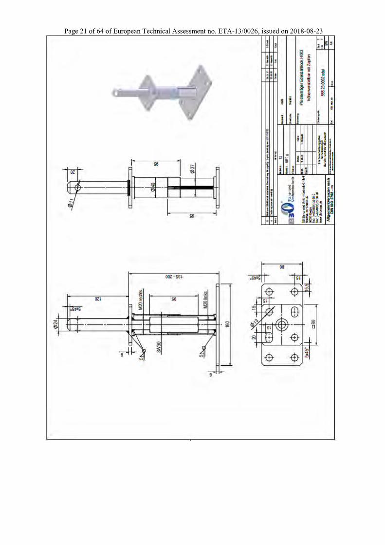
H001 555 23 0000 4 x F 12x120mm - 130/130 135 to 200 a a
H002 555 23 0001 4 Nails 4x40mm - 70 to 170
/116 139 to 204 - -
H003 555 23 0002 4x F 12x120mm
1 x D Ø10 or
1 x Bo M10 130/130 135 to 200 a + 60 a
H004 555 23 0003 - 2 x D Ø10
or 2 x Bo Ø10
100/130 135 to 200 a +13 a +100
H100 550 13 0004 4x F 12x120mm - 130/130 140 to 205 a a
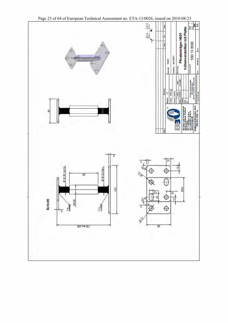
BB00-0035-009 BB00-0035-013 2 x F 12x120mm - 140/140
130/130 122 to 180 a a
* P = partial thread; F = full thread ** The position of the fasteners shall always be at maximum distance to the end grain of the post.
Table A.2 Specifications of the metal fasteners according to EN 14592
Fastener type
Size (mm) Material Finish
Diameter Length Threaded length
Dowels 10 mm S235 Galvanic zinc coating
Bolts 10 mm 4.6 Galvanic zinc coating
Nails 4 mm min 40 mm - fu,k ≥ 600 N/mm2 Galvanic zinc coating
Screws 6 mm min 80 mm min 48 mm fu,k ≥ 360 N/mm2 Galvanic zinc coating
Screws 10 mm min 50 mm min 35 mm fu,k ≥ 360 N/mm2 Galvanic zinc coating
Screws 10 mm min 80 mm min 48 mm fu,k ≥ 360 N/mm2 Galvanic zinc coating
Screws 10 mm min 100 mm min 88 mm fu,k ≥ 360 N/mm2 Galvanic zinc coating
Screws 12 mm min 120 mm min 105 mm fu,k ≥ 360 N/mm2 Galvanic zinc coating The load-carrying-capacities of the metal fasteners were calculated according to Eurocode 5 for lateral loads. The contribution to the load-carrying capacity due to the rope effect was considered according to Eurocode 5.
Page 10 of 64 of European Technical Assessment no. ETA-13/0026, issued on 2018-08-23
Annex B
Characteristic load-carrying capacities
Table B.1 Characteristic load-carrying capacities for post bases in kN
Post Base F1 (Compression) F1 (Tension) F2 /F3 F4/F5
Type Metal Fasteners Timber Steel Timber Steel Timber Steel Timber Steel
A001 4 x F 12x120 mm 100,0 100,0 87,8 18,7 8,5 12,0 3,0 12,0 3,0
M (T) M,0 M,1 M (C) M,0 M (C) M,0 M (C) M,0
A002
2 x P 10x80 mm 26,3 32,5 - 9,2 2,0 - - - -
4 x P 6x80 mm 26,3 32,5 - 9,2 2,0 - - - -
M (T) M,0 - M (C) M,0 - - - -
A003 2 x D Ø10 or 2 x Bo M10 100,7 - 87,8 25,1 7,3 13,1 0,9 2,5 1,7
M (T) - M,1 M (C) M,0 M (T) M,0 M (C) M,0
A004
1 x D Ø10 91,5 91,5 87,8 6,4 7,3 - - 5,1 0,9
1 x Bo M10 91,5 91,5 87,8 7,6 7,3 - - 6,4 0,9
M (T) M,0 M,1 M (J) M,0 - - M (C) M,0
H001 4 x F 12x120 mm 55,9 55,9 57,9 18,7 6,1 12,0 0,8 6,0 1,3
M (T) M,0 M,1 M (C) M,0 M (C) M,0 M (C) M,0
H002 4 x N 4x40mm 32,6 30,6 - 5,5 0,9 - - - -
M (T) M,0 - M (C) M,0 - - - -
H003
4 x F 12x120 mm 44,8 44,8 57,9 18,7 6,1 12,0 0,8 6,0 1,3
1 x D Ø10 44,8 44,8 57,9 6,4 6,1 5,1 0,5 - -
1 x Bo M10 44,8 44,8 57,9 7,6 6,1 6,4 0,5 - -
M (T) M,0 M,1 M (C) M,0 M (C) M,0 - -
H004 2 x D Ø10 or 2 x Bo M10 61,6 61,6 57,9 25,1 6,1 2,5 0,7 13,1 0,9
M (T) M,1 M,1 M (C) M,0 M (T) M,0 M (T) M,0
H100 4 x F 12x120 mm 55,9 55,9 57,3 18,7 6,1 12,0 0,8 12,0 1,3
M (T) M,0 M,1 M (C) M,0 M (C) M,0 M (C) M,0
BRN M20
4 x F 10x100 mm 84,5 - 64,2 14,8 10,0 9,5 1,7 9,5 1,7
M (T) - M,1 M (C) M,0 M (C) M,0 M (C) M,0
M (T) = partial factor for solid timber according to EN 1995-1-1 and national annex M (C) = partial factor for connections according to EN 1995-1-1 and national annex M,0; M,1 = partial factor according to EN 1993-1-1 and national annex
Page 11 of 64 of European Technical Assessment no. ETA-13/0026, issued on 2018-08-23
Continuation of Table B.1 Characteristic load-carrying capacities for post bases in kN
Post Base F1 (Compression) F1 (Tension) F2 /F3 F4/F5
Type Size Timber Steel Timber Steel Timber Steel Timber Steel
ASH 2,5 mm
71 7,56 37,5 7,56 7,03 7,61 6,77 7,61 6,77
81 7,56 37,5 7,56 8,81 10,1 10,3 10,1 10,3
91 7,56 37,5 7,56 13,3 13,0 10,3 13,0 10,3
101 7,56 37,5 7,56 13,3 15,5 10,3 15,5 10,3
121 7,56 37,5 7,56 13,3 15,5 10,3 15,5 10,3
141 7,56 37,5 7,56 13,3 15,5 10,3 15,5 10,3
161 7,56 37,5 7,56 13,3 15,5 10,3 15,5 10,3
201 7,56 37,5 7,56 13,3 18,7 12,5 18,7 12,5
M (C) M,2 M (C) M,0 M (C) M,0 M (T) M,0
ASH 2,0 mm
101
121
141
161
201
M (C) M,2 M (C) M,0 M (C) M,0 M (T) M,0
ASH r
Ø 80 7,56 37,5 7,56 4,54 7,59 3,20 7,59 3,20
Ø 100 7,56 37,5 7,56 6,40 12,3 5,64 12,3 5,64
Ø 120 7,56 37,5 7,56 5,26 18,1 5,56 18,1 5,56
Ø 140 7,56 37,5 7,56 6,29 24,9 7,78 24,9 7,78
M (C) M,2 M (C) M,0 M (T) M,0 M (T) M,0
ASH g
85 15,1 38,9 15,1 12,4 5,04 4,23 5,04 4,23
105 22,8 59,0 22,8 10,0 10,1 4,74 10,1 4,74
M (C) M,2 M (C) M,0 M (C) M,0 M (C) M,0
ASH z
101 21,0 32,2 7,56 5,97 10,8 3,32 6,74 3,89
121 29,4 45,0 7,56 6,93 10,8 4,61 7,01 3,73
141 37,8 57,9 7,56 3,85 10,8 2,98 7,31 4,74
161 50,4 77,2 7,32 18,6 17,3 16,4 11,3 8,69
201 63,0 96,5 7,32 18,6 17,3 20,5 11,7 9,85
M (T) M,0 M (C) M,0 M (T) M,0 M (T) M,0
M (T) : partial factor for solid timber according to EN 1995-1-1 and national annex M (C) : partial factor for connections according to EN 1995-1-1 and national annex M,0; M,1; M,2 : partial factor according to EN 1993-1-1 and national annex
Page 12 of 64 of European Technical Assessment no. ETA-13/0026, issued on 2018-08-23
Continuation of Table B.1 Characteristic load-carrying capacities for post bases in kN
Post Base F1 (Compression) F1 (Tension) F2 /F3 F4/F5
Type Size Timber Steel Timber Steel Timber Steel Timber Steel
PFTR S
71 7,76 13,3 7,36 7,99 5,41 2,96 3,38 3,26
81 7,76 13,3 7,36 6,74 5,41 2,71 3,38 3,26
91 7,76 13,3 7,36 5,83 5,41 2,35 3,38 3,26
101 7,76 13,3 7,36 5,13 5,41 2,07 3,38 3,26
121 7,76 13,3 7,36 4,15 5,41 1,67 3,38 3,26
141 7,76 13,3 7,36 3,48 5,41 1,40 3,38 3,26
M (C) M,0 M (C) M,0 M (C) M,0 M (T) M,0
PFTR a
71 14,6 51,4 7,32 82,9 4,88 6,32 3,55 7,10
81 14,6 51,4 7,32 82,9 4,88 6,32 3,55 7,10
91 14,6 51,4 7,32 82,9 4,88 6,32 3,55 7,10
101 14,6 51,4 7,32 82,9 4,88 6,32 3,55 7,10
121 14,6 51,4 7,32 82,9 4,88 6,32 3,55 7,10
141 14,6 51,4 7,32 82,9 4,88 6,32 3,55 7,10
M (C) M,1 M (C) M,2 M (C) M,0 M (T) M,0
PFTR 200 U
71 45,9 45,9 7,32 5,59 4,88 2,85 4,70 6,33
81 45,9 45,9 7,32 4,57 4,88 2,85 4,70 6,33
91 45,9 45,9 7,32 3,86 4,88 2,85 4,70 6,33
101 45,9 45,9 7,32 3,35 4,88 2,85 4,70 6,33
121 45,9 45,9 7,32 2,64 4,88 2,85 4,70 6,33
141 45,9 45,9 7,32 2,18 4,88 2,85 4,70 6,33
M (T) M,0 M (C) M,0 M (C) M,0 M (C) M,0
PFTR 250 U
71 45,9 45,9 7,32 5,59 4,88 2,18 4,56 4,04
81 45,9 45,9 7,32 4,57 4,88 2,18 4,56 4,04
91 45,9 45,9 7,32 3,86 4,88 2,18 4,56 4,04
101 45,9 45,9 7,32 3,35 4,88 2,18 4,56 4,04
121 45,9 45,9 7,32 2,64 4,88 2,18 4,56 4,04
141 45,9 45,9 7,32 2,18 4,88 2,18 4,56 4,04
M (T) M,0 M (C) M,0 M (C) M,0 M (C) M,0
PFTR hv
80 53,5 53,5 18,7 21,1 12,0 0,92 12,0 0,92
100 53,5 53,5 18,7 7,53 12,0 0,92 12,0 0,92
M (T M,0 M (C) M,0 M (C) M,0 M (C) M,0
M (T) : partial factor for solid timber according to EN 1995-1-1 and national annex M (C) : partial factor for connections according to EN 1995-1-1 and national annex M,0; M,1 ; M,2 : partial factors according to EN 1993-1-1 and national annex
Page 13 of 64 of European Technical Assessment no. ETA-13/0026, issued on 2018-08-23
F4/F5 F4/F5
F2/F3
F2/F3F2/F
3
F2/F3
F1F1
F1
F2/F3
F4/F5
e
e
eF4/F5
a
e
F2/F3e
F1
e
a
ee
F2/F3
F2/F3
F4/F5
F4/F5e
a
e
F4/F5 F4/F5
F2/F3
F2/F3F2/F
3
F2/F3
F1F1
F1
F2/F3
F4/F5
e
e
eF4/F5
a
e
F2/F3e
F1
e
a
ee
F2/F3
F2/F3
F4/F5
F4/F5e
a
e
F4/F5 F4/F5
F2/F3
F2/F3F
2/F3
F2/F3
F1F1
F1
F2/F3
F4/F5
e
e
eF4/F5
a
e
F2/F3e
F1
e
a
ee
F2/F3
F2/F3
F4/F5
F4/F5e
a
e
Definitions of forces, their directions and eccentricity
• Force F1: tensile or compression load
• Force F2 / F3: horizontal parallel to the ground plate of the post base and perpendicular to the bolts or dowels
• Force F4 / F5: horizontal load parallel to the ground plate of the post base and parallel to the bolts or dowels
Acting forces
F1 axial force (tension or compression) acting along the central axis of the joint F2 and F3 horizontal force perpendicular to the ground plate of the post base acting with the lever
arm eF2/F3 above the foundation F4 and F5 horizontal force parallel to the ground plate of the post base acting with the lever arm
eF4/F5 above the foundation
F1
F2 / F3
F4 / F5
F1
F2 / F3
F4 / F5
Page 14 of 64 of European Technical Assessment no. ETA-13/0026, issued on 2018-08-23
Combined forces
If the forces F1 and F2/F3 or F4/F5 act at the same time, the following inequality shall be fulfilled:
i,Ed
i,Rd
F1
F
The forces F2 and F3 or F4 and F5 are forces with opposite direction. Therefore only one force F2 or F3, and F4 or F5, respectively, is able to act simultaneously with F1.
Page 15 of 64 of European Technical Assessment no. ETA-13/0026, issued on 2018-08-23
Page 16 of 64 of European Technical Assessment no. ETA-13/0026, issued on 2018-08-23
Page 17 of 64 of European Technical Assessment no. ETA-13/0026, issued on 2018-08-23
Page 18 of 64 of European Technical Assessment no. ETA-13/0026, issued on 2018-08-23
Page 19 of 64 of European Technical Assessment no. ETA-13/0026, issued on 2018-08-23
Page 20 of 64 of European Technical Assessment no. ETA-13/0026, issued on 2018-08-23
Page 21 of 64 of European Technical Assessment no. ETA-13/0026, issued on 2018-08-23
Page 22 of 64 of European Technical Assessment no. ETA-13/0026, issued on 2018-08-23
Page 23 of 64 of European Technical Assessment no. ETA-13/0026, issued on 2018-08-23
Page 24 of 64 of European Technical Assessment no. ETA-13/0026, issued on 2018-08-23
Page 25 of 64 of European Technical Assessment no. ETA-13/0026, issued on 2018-08-23
Page 26 of 64 of European Technical Assessment no. ETA-13/0026, issued on 2018-08-23
Page 27 of 64 of European Technical Assessment no. ETA-13/0026, issued on 2018-08-23
Page 28 of 64 of European Technical Assessment no. ETA-13/0026, issued on 2018-08-23
Page 29 of 64 of European Technical Assessment no. ETA-13/0026, issued on 2018-08-23
Page 30 of 64 of European Technical Assessment no. ETA-13/0026, issued on 2018-08-23
Page 31 of 64 of European Technical Assessment no. ETA-13/0026, issued on 2018-08-23
Page 32 of 64 of European Technical Assessment no. ETA-13/0026, issued on 2018-08-23
Page 33 of 64 of European Technical Assessment no. ETA-13/0026, issued on 2018-08-23
Page 34 of 64 of European Technical Assessment no. ETA-13/0026, issued on 2018-08-23
Page 35 of 64 of European Technical Assessment no. ETA-13/0026, issued on 2018-08-23
Page 36 of 64 of European Technical Assessment no. ETA-13/0026, issued on 2018-08-23
Page 37 of 64 of European Technical Assessment no. ETA-13/0026, issued on 2018-08-23
Page 38 of 64 of European Technical Assessment no. ETA-13/0026, issued on 2018-08-23
Page 39 of 64 of European Technical Assessment no. ETA-13/0026, issued on 2018-08-23
Page 40 of 64 of European Technical Assessment no. ETA-13/0026, issued on 2018-08-23
Page 41 of 64 of European Technical Assessment no. ETA-13/0026, issued on 2018-08-23
Page 42 of 64 of European Technical Assessment no. ETA-13/0026, issued on 2018-08-23
Page 43 of 64 of European Technical Assessment no. ETA-13/0026, issued on 2018-08-23
Page 44 of 64 of European Technical Assessment no. ETA-13/0026, issued on 2018-08-23
Page 45 of 64 of European Technical Assessment no. ETA-13/0026, issued on 2018-08-23
Page 46 of 64 of European Technical Assessment no. ETA-13/0026, issued on 2018-08-23
Page 47 of 64 of European Technical Assessment no. ETA-13/0026, issued on 2018-08-23
Page 48 of 64 of European Technical Assessment no. ETA-13/0026, issued on 2018-08-23
Page 49 of 64 of European Technical Assessment no. ETA-13/0026, issued on 2018-08-23
Page 50 of 64 of European Technical Assessment no. ETA-13/0026, issued on 2018-08-23
Page 51 of 64 of European Technical Assessment no. ETA-13/0026, issued on 2018-08-23
Page 52 of 64 of European Technical Assessment no. ETA-13/0026, issued on 2018-08-23
Page 53 of 64 of European Technical Assessment no. ETA-13/0026, issued on 2018-08-23
Page 54 of 64 of European Technical Assessment no. ETA-13/0026, issued on 2018-08-23
Page 55 of 64 of European Technical Assessment no. ETA-13/0026, issued on 2018-08-23
Page 56 of 64 of European Technical Assessment no. ETA-13/0026, issued on 2018-08-23
Page 57 of 64 of European Technical Assessment no. ETA-13/0026, issued on 2018-08-23
Page 58 of 64 of European Technical Assessment no. ETA-13/0026, issued on 2018-08-23
Page 59 of 64 of European Technical Assessment no. ETA-13/0026, issued on 2018-08-23
Page 60 of 64 of European Technical Assessment no. ETA-13/0026, issued on 2018-08-23
Page 61 of 64 of European Technical Assessment no. ETA-13/0026, issued on 2018-08-23
Page 62 of 64 of European Technical Assessment no. ETA-13/0026, issued on 2018-08-23
Page 63 of 64 of European Technical Assessment no. ETA-13/0026, issued on 2018-08-23
Page 64 of 64 of European Technical Assessment no. ETA-13/0026, issued on 2018-08-23