INSTITUTO DE CIENCIAS DE LA CONSTRUCCIÓN EDUARDO TORROJA C/ Serrano Galvache n. 4. 28033 Madrid (Spain) Tel.: (34) 91 302 04 40 / Fax: (34) 91 302 07 00 [email protected]www.ietcc.csic.es Member of www.eota.eu European Technical Assessment ETA 14/0226 of 20/ 04/ 2015 English translation prepared by IETcc. Original version in Spanish language General Part Technical Assessment Body issuing the ETA and designated according to Article 29 of the Regulation (EU) Nº305/2011: Instituto de Ciencias de la Construcción Eduardo Torroja (IETcc) Trade name of the construction product VERMIPLASTER ® BD MP 75 SL FIRE Product family to which the construction product belongs Rendering intended for Fire Resisting Application of building elements Manufacturer KNAUF Gips KG Am Bahnhof 7. 97346 Iphofen – Germany Manufacturing plant(s) Carretera. de Incar, km 2,8 Escúzar 18130 (Granada) – Spain This European Technical Assessment contains 15 pages including: 1 Annex, which form an integral part of this assessment, Annex 2, contain confidential information and is not included in the ETA when that assessment is publicly available This European Technical Assessment is issued in accordance with regulation (EU) N o 305/2011, on the basis of Guideline for European Technical Assesmment (ETAG) nº 018 part 1-3, used as European Assessment Document (EAD) This version replaces ETA 14/0226 issued on 14/ 07/ 2014 Designated according to Article29 of Regulation (EU) Nº 305/2011
Transcript
INSTITUTO DE CIENCIAS DE LA CONSTRUCCIÓN EDUARDO TORROJA C/ Serrano Galvache n. 4. 28033 Madrid (Spain) Tel.: (34) 91 302 04 40 / Fax: (34) 91 302 07 00 [email protected] www.ietcc.csic.es
Member of
www.eota.eu
European Technical Assessment ETA 14/0226 of 20/ 04/ 2015
English translation prepared by IETcc. Original version in Spanish language
General Part
Technical Assessment Body issuing the ETA and designated according to Article 29 of the Regulation (EU) Nº305/2011:
Instituto de Ciencias de la Construcción Eduardo Torroja (IETcc)
Trade name of the construction product
VERMIPLASTER® BD
MP 75 SL FIRE
Product family to which the construction product belongs
Rendering intended for Fire Resisting Application of building elements
Manufacturer
KNAUF Gips KG Am Bahnhof 7. 97346 Iphofen – Germany
Manufacturing plant(s) Carretera. de Incar, km 2,8 Escúzar 18130 (Granada) – Spain
This European Technical Assessment contains
15 pages including: 1 Annex, which form an integral part of this assessment, Annex 2, contain confidential information and is not included in the ETA when that assessment is publicly available
This European Technical Assessment is issued in accordance with regulation (EU) No 305/2011, on the basis of
Guideline for European Technical Assesmment (ETAG) nº 018 part 1-3, used as European Assessment Document (EAD)
This version replaces ETA 14/0226 issued on 14/ 07/ 2014
Translations of this European Technical Assessment in other languages shall fully correspond to the original
issued document and should be identified as such.
Communication of this European Technical Assessment, including transmission by electronic means, shall be
in full (excepted the confidential Annex(es) referred to above). However, partial reproduction may be made,
with the written consent of the issuing Technical Assessment Body. Any partial reproduction has to be
identified as such.
This European Technical Assessment may be withdrawn by the issuing Technical Assessment Body, in
particular pursuant to information by the Commission according to Article 25 Paragraph 3 of Regulation (EU)
No 305/2011.
ETA 14/0226 of 20/04/2015 – page 3 of 15
SPECIFIC PARTS OF THE EUROPEAN TECHNICAL ASSESSMENT
1 Technical description of the product
The VERMIPLASTER® BD/ MP 75 SL FIRE product is a mortar of fine granule based in calcium sulphate. This
product is lightened with expansive minerals and formulated with several additives to improve the application and its performances. The application is performed by spray; the product powder is mixed with water in appropriated machines, or manually. Once the mortar is hardened, conforms a continuous rendering completely bonded to the support (steel with and without primer, galvanized steel and sheet of galvanized steel).
The thickness of the applied product ranges from 6 - 42 mm, with a consumption of 4,5-5 kg/m2/cm thickness.
The final assembly contains a rendering, several primers (base epoxy, alkyd and silicate zinc) when it is applied on steel supports (optional).
According to ETAG 018-3, this ETA is assessed under use conditions: Option 3.
2 Specification of the intended use in accordance with the applicable EAD
The intended use of this product is the rendering of indoor building load-bearing constructive elements to increase the fire resistance in case of fire, keeping the resistance, integrity and insulation (REI) of the building elements until the fire extinction or the building evacuation.
This Product fulfils the Essential Requirements nº 2 (Safety in case of fire), nº 3 (Hygiene, health and the environment) and nº 4 (Safety in use) of the Construction products Regulation 305/2011.
This product has a category of use related to environmental conditions:
- Type Y (included Z1, Z2): Renderings intended for internal and semi-exposed conditions (semi-exposed conditions include temperatures below 0°C, but not exposed to rain and limited exposure to UV)
Use category related to the element(s) intended to be protected:
- Type 4: Fire Protective Products to protect load-bearing steel elements. Beams and columns with 3 and 4 exposed faces. With a section factor of <300 m
-1. Temperature ranges from 350ºC to 650ºC. R15-R240.
- Type 10. Further intended uses, related to fire compartmentalisation or protection of fire performance, not covered by above Types.
The provisions made in this European Technical Approval (ETA) are based on an assumed intended working life of the system of 25 years, provided that the product is subject to appropriate use and maintenance in accordance with Chapter 5. The indication given on the working life cannot be interpreted as a guarantee given by the manufacturer, but are only to be regarded as a means for choosing the right products in relation to the expected economically reasonable working life of the works. "Assumed intended working life" means that, when an assessment following the ETAG provisions is made, and when this working life has elapsed, the real working life may be, in normal use conditions, considerably longer without major degradation affecting the Essential Requirements. Application on site. The suitability of use of this product can only be assumed if this is applied according to the manufacturer‟s instructions, which are part of the MTD to this ETA placed at IETcc.
Particularly, it is recommended to consider.
- The application has to carried out by skilled labor, - It can only be used the components of the Product indicated in this ETA, - It is necessary to control the thickness of the applied product during application, - The support to protect must be clean, dry and without dust or grease in order not to affect the adherence
of VERMIPLASTER® BD/ MP 75 SL FIRE mortar.
- The recommended mixing water (water/powder) is 1,1 to 1,3 so for a VERMIPLASTER® BD/ MP75 SL
FIRE sacks is necessary 12 ± 2 L of water.
ETA 14/0226 of 20/04/2015 – page 4 of 15
- The application must be performed by spray, mixing the product with water in the projection machine, or manually. Usually the powder is mixed with water in usual mixing machines. The water flow of the machine must be regulated until achieving a mass/paste/plasticity that covers uniformly and does not fell down. In order to achieve a uniform finishing of VERMIPLASTER
® BD/ MP75 SL FIRE it must be used
nozzles from 10 to 12 mm. - The adherence test is situ should be at least 80% of the values enclosed in this ETA.
- The density of the applied rendering on site will not vary more than 490 kg/m3 15%. If it was more than
15%, it would be needed to carry out adherence tests. - The hardened product will not present cracks, according to the test performed in this evaluation.
- Before, the installation of VERMIPLASTER® BD/ MP 75 SL FIRE, it is recommended to read its security
card.
Requirements to use primers on different supports and its compatibility with its rendering
- The alkyd, epoxy and silicate zinc primers are compatible with VERMIPLASTER® BD/ MP75 SL FIRE,
however, the application of VERMIPLASTER® BD/ MP75 SL FIRE can be carried out directly on clean
steel because it does not cause directly any corrosion on steel. Adherence can vary from one primer to another, depending on the primer quality and the finishing state of the surface. Oily primers and those which give off pigments are not recommended.
- The ETA-Guideline is not designed to cover the application of rendering over any existing coating (e.g. „old‟ existing paint) or rendering. It is therefore assumed that: o Any existing coating or rendering must be completely removed before the application. o If it could not be removed, it must be consult with the manufacturer.
Circumstances in which the rendering needs reinforcements. Although it has not been evaluated in this ETA, in cases where the mechanical resistance needs to be improved, it is recommended to place a mesh. In cases that the state of the surface does not assure an adequate adherence, please check it with the manufacturer.
Finishing of the final aspect of the rendering. Any repairing required may be performed manually by using a trowel, etc, Its finishing is rough but, if desired; it can be smoothed using a trowel or any other brickwork tool intended for this use.
Application limitations due to certain environments
- The recommended environmental temperature of the product to be applied will be between 5ºC and 40ºC and it will be not admitted support temperatures upper to 45ºC. In other conditions it will need to follow the manufacturer‟s instructions.
- During the application and drying time, the product has to be protected against the water rain. - Curing and drying must not be exposed to strong winds during projection to avoid a rapid dry.
Incompatibility with other Fire protection materials. For these special cases, it is needed to check it with the manufacturer.
Recommendations of use, maintenance and repair. It is recommended to carry out regularly control inspections to check the state of the product (damages, cracks, cleanliness, etc). The repair procedure will be carried out by complete disposal of the damaged product, preparation of the support (cleanliness) and new application of VERMIPLASTER
® BD / MP75 SL FIRE sprayed or manually if the reparation size is small (<
1000 cm2). When the area to repair is significant, it is recommend to use a mesh fixed to the support shall be
used.
Further application details are laid down in the MTD place at IETcc.
3 Performance of the product and references to the methods used for its assessment
The assessment of the fitness of the VERMIPLASTER® BD/ MP75 SL FIRE for the intended use regard to the
Essential Requirements nº 2, 3 and 4 was performed in compliance with the “Guideline for European Technical Approval of Fire Protective Products, ETAG 018, Part 1”General” and Part 3 “Renderings and Rendering Kits Intended for Fire Resisting Applications”.
ETA 14/0226 of 20/04/2015 – page 5 of 15
3.1 Characteristics of Product “VERMIPLASTER® BD/ MP75 SL FIRE”
1
3.1.1 ER. 2 Safety in case of fire
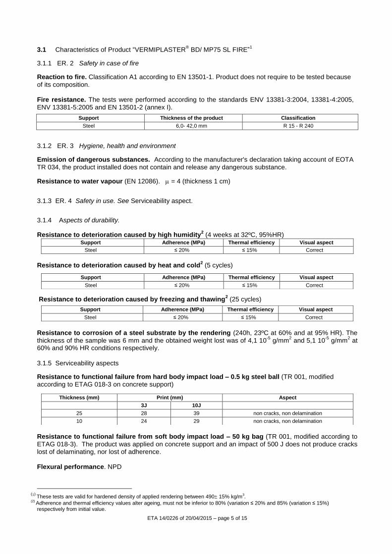
Reaction to fire. Classification A1 according to EN 13501-1. Product does not require to be tested because of its composition. Fire resistance. The tests were performed according to the standards ENV 13381-3:2004, 13381-4:2005, ENV 13381-5:2005 and EN 13501-2 (annex I).
Support Thickness of the product Classification
Steel 6,0- 42,0 mm R 15 - R 240
3.1.2 ER. 3 Hygiene, health and environment
Emission of dangerous substances. According to the manufacturer's declaration taking account of EOTA TR 034, the product installed does not contain and release any dangerous substance.
Resistance to water vapour (EN 12086). = 4 (thickness 1 cm)
3.1.3 ER. 4 Safety in use. See Serviceability aspect.
3.1.4 Aspects of durability.
Resistance to deterioration caused by high humidity2 (4 weeks at 32ºC, 95%HR)
Support Adherence (MPa) Thermal efficiency Visual aspect
Steel ≤ 20% ≤ 15% Correct
Resistance to deterioration caused by heat and cold
2 (5 cycles)
Resistance to deterioration caused by freezing and thawing2 (25 cycles)
Resistance to corrosion of a steel substrate by the rendering (240h, 23ºC at 60% and at 95% HR). The thickness of the sample was 6 mm and the obtained weight lost was of 4,1 10
-5 g/mm
2 and 5,1 10
-5 g/mm
2 at
60% and 90% HR conditions respectively. 3.1.5 Serviceability aspects
Resistance to functional failure from hard body impact load – 0.5 kg steel ball (TR 001, modified according to ETAG 018-3 on concrete support)
Resistance to functional failure from soft body impact load – 50 kg bag (TR 001, modified according to ETAG 018-3). The product was applied on concrete support and an impact of 500 J does not produce cracks lost of delaminating, nor lost of adherence. Flexural performance. NPD
(1)
These tests are valid for hardened density of applied rendering between 490 15% kg/m3.
(2) Adherence and thermal efficiency values alter ageing, must not be inferior to 80% (variation ≤ 20% and 85% (variation ≤ 15%) respectively from initial value.
Support Adherence (MPa) Thermal efficiency Visual aspect
Steel ≤ 20% ≤ 15% Correct
Support Adherence (MPa) Thermal efficiency Visual aspect
Steel ≤ 20% ≤ 15% Correct
Thickness (mm) Print (mm) Aspect
3J 10J
25 28 39 non cracks, non delamination
10 24 29 non cracks, non delamination
ETA 14/0226 of 20/04/2015 – page 6 of 15
Air erosion. NPD Adherence (EGOLF SM/5)
Support Thickness Adherence (MPa)
Steel
42 mm
≥ 0.06
25 mm
6 mm
Steel + Epoxy primer
42 mm
25 mm
6 mm
Steel + Alkyd primer
42 mm
25 mm
6 mm
Steel + Silicate Zinc primer
42 mm
25 mm
6 mm
Galvanized steel 25 mm
10 mm
Thermal efficiency and aspect with the different primers
Support Thermal efficiency Visual aspect
Steel + Epoxy primer ≤ 15%3 Correct
Steel + Alkyd primer ≤ 15% Correct
Steel + Silicate Zinc primer ≤ 15% Correct
Galvanized steel ≤ 15% Correct
3.2 Identification of components
The characteristics of the components of this product show the following values, which are within the respective requirements and tolerances stated in the Manufacture Technical Dossier (MTD).
4. Assessment and verification of constancy of performance (AVCP) system applied, with reference to its legal base
System of attestation of conformity. The European Commission according to mandate Construct 98/311, Annex 3 (taking into account decision 1999/454/EC of the Commission) on the procedure of attestation of conformity for the procedure of attestation of conformity (Annex III of EU Regulation 305/2011) has laid down for this type of material:
Product Intended uses Level or Classes System
VERMIPLASTER BD MP 75 SL FIRE
Rendering intended for Fire Resisting Application of building elements
Any 1
(3)
Variation of the test time respect to the same sample un-primed steel sheet
Properties VERMIPLASTER BD
Binder content (volume) 24 %
TG / ATD IETcc
Mixing ratio (water/powder) 1,0-1,2
Colour White
Density Powder (kg/m
3)
Paste (EN 1015-6) Hardened (EN 1015-10)
402 (320-420)
1080 (900-1200) 490 (420-565)
Dry extract 45ºC (% weight residue) > 99
Ash content 450°C (% weight residue) > 95
Flexural strength (EN 1015-11) (MPa) > 0.2
Compressive strength (EN 1015-11) (MPa) > 0.4
ETA 14/0226 of 20/04/2015 – page 7 of 15
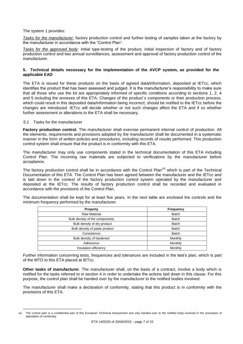
The system 1 provides:
Tasks for the manufacturer: factory production control and further testing of samples taken at the factory by the manufacturer in accordance with the “Control Plan”.
Tasks for the approved body: initial type-testing of the product, initial inspection of factory and of factory production control and two annual surveillances, assessment and approval of factory production control of the manufacturer.
5. Technical details necessary for the implementation of the AVCP system, as provided for the applicable EAD
The ETA is issued for these products on the basis of agreed data/information, deposited at IETcc, which
identifies the product that has been assessed and judged. It is the manufacturer‟s responsibility to make sure
that all those who use the kit are appropriately informed of specific conditions according to sections 1, 2, 4
and 5 including the annexes of this ETA. Changes of the product´s components or their production process,
which could result in this deposited data/information being incorrect, should be notified to the IETcc before the
changes are introduced. IETcc will decide whether or not such changes affect the ETA and if so whether
further assessment or alterations to the ETA shall be necessary. 5.1 Tasks for the manufacturer
Factory production control. The manufacturer shall exercise permanent internal control of production. All the elements, requirements and provisions adopted by the manufacturer shall be documented in a systematic manner in the form of written policies and procedures, including records of results performed. This production control system shall ensure that the product is in conformity with this ETA.
The manufacturer may only use components stated in the technical documentation of this ETA including Control Plan. The incoming raw materials are subjected to verifications by the manufacturer before acceptance.
The factory production control shall be in accordance with the Control Plan(4)
which is part of the Technical Documentation of this ETA. The Control Plan has been agreed between the manufacturer and the IETcc and is laid down in the context of the factory production control system operated by the manufacturer and deposited at the IETcc. The results of factory production control shall be recorded and evaluated in accordance with the provisions of the Control Plan.
The documentation shall be kept for at least five years. In the next table are enclosed the controls and the minimum frequency performed by the manufacturer.
Property Frequency
Raw Material Batch
Bulk density of the components Batch
Bulk density of dry product Batch
Bulk density of paste product Batch
Consistence Batch
Bulk density of hardened Monthly
Adherence Monthly
Insulation efficiency Monthly
Further information concerning tests, frequencies and tolerances are included in the test‟s plan, which is part of the MTD to this ETA placed at IETcc. Other tasks of manufacturer. The manufacturer shall, on the basis of a contract, involve a body which is notified for the tasks referred to in section 4 in order to undertake the actions laid down in this clause. For this purpose, the control plan shall be handed over by the manufacturer to the notified bodies involved.
The manufacturer shall make a declaration of conformity, stating that this product is in conformity with the provisions of this ETA.
(4) The control plan is a confidential part of this European Technical Assessment and only handed over to the notified body involved in the procedure of
attestation of conformity.
ETA 14/0226 of 20/04/2015 – page 8 of 15
5.2 Tasks for the Notified body
Initial type-testing of the product. The initial type-testing have been carried out by the IETcc to issue this ETA which corresponds to chapter 5 of the Guideline for European Technical Approval of Fire Protective Products, ETAG 018, Part 1 ”General” and Part 3 “Renderings and Rendering Kits Intended for Fire Resisting Applications”.
The initial type-testing of this ETA have been carried out by the IETcc on samples from the current pro-duction. The IETcc has assessed the results of these tests in accordance with chapter 6 of this ETA –Guideline, as part of the ETA issuing procedure. Initial inspection of factory and production control. The IETcc has checked that, in accordance with the MTD, factory conditions and production control allow the manufacturer to ensure the consistency and homogeneity of the manufactured product and its traceability, in order to assure the final characteristics of the product. Continuous surveillance, assessment and approval of Factory Production Control. The Notified body shall visit the factory at least twice a year. Surveillance of the manufacturing process shall include:
- Inspection of the documentation of factory production control, to ensure continuing compliance with the provisions of the ETA,
- Identification of changes by comparing data obtained during the initial inspection or during the last visit.
In cases where the provisions of the European Technical Approval and its “Control Plan” are no longer fulfilled the certification body (IETcc) shall withdraw the certificate of conformity.
Issued in Madrid on 20 April 2015 by
Instituto de Ciencias de la Construcción Eduardo Torroja
CONSEJO SUPERIOR DE INVESTIGACIONES CIENTÍFICAS c/ Serrano Galvache 4. 28033 Madrid (Spain)
On behalf of the Instituto de Ciencias de la Construcción Eduardo Torroja
Marta Castellote Armero Directora
ETA 14/0226 of 20/04/2015 – page 9 of 15
Annex I. Fire resistance tests
Beams and Columns of steel with 3 or 4 exposed faces (Report of test AFITI LICOF 1811T09-2) according to annex H ENV 13381-4:2005).
Section factor (m
-1)
Classification of Fire Resistance 350ºC
R15 R30 R45 R60 R90 R120 R180 R240
≤ 65 6 8 11 14 19 25 37 - - -
70 6 8 11 14 20 26 38 - - -
75 6 9 12 15 21 27 39 - - -
80 6 9 12 15 21 27 40 - - -
85 6 9 12 15 22 28 41 - - -
90 6 9 12 16 22 29 41 - - -
95 6 9 13 16 22 29 42 - - -
100 6 10 13 16 23 30 - - - - - -
110 7 10 13 17 24 30 - - - - - -
120 7 10 14 17 24 31 - - - - - -
130 7 10 14 18 25 32 - - - - - -
140 7 11 14 18 25 32 - - - - - -
150 7 11 15 18 26 33 - - - - - -
160 7 11 15 19 26 33 - - - - - -
170 7 11 15 19 26 34 - - - - - -
180 8 11 15 19 27 34 - - - - - -
190 8 12 15 19 27 35 - - - - - -
200 8 12 16 19 27 35 - - - - - -
210 8 12 16 20 27 35 - - - - - -
220 8 12 16 20 28 36 - - - - - -
230 8 12 16 20 28 36 - - - - - -
240 8 12 16 20 28 36 - - - - - -
250 8 12 16 20 28 36 - - - - - -
260 8 12 16 20 28 36 - - - - - -
270 8 12 16 20 29 37 - - - - - -
280 8 12 16 21 29 37 - - - - - -
290 8 12 17 21 29 37 - - - - - -
300 8 13 17 21 29 37 - - - - - -
Minimum thickness (mm) of product to keep the profile temperature below 350ºC
Note: The cursive figures correspond to extrapolated values.
ETA 14/0226 of 20/04/2015 – page 10 of 15
Section factor (m
-1)
Classification of Fire Resistance 400ºC
R15 R30 R45 R60 R90 R120 R180 R240
≤ 65 6 6 9 12 17 22 33 - - -
70 6 7 10 12 18 23 34 - - -
75 6 7 10 13 18 24 35 - - -
80 6 7 10 13 19 24 36 - - -
85 6 8 11 13 19 25 37 - - -
90 6 8 11 14 20 26 38 - - -
95 6 8 11 14 20 26 38 - - -
100 6 8 11 14 21 27 39 - - -
110 6 9 12 15 21 28 40 - - -
120 6 9 12 15 22 28 41 - - -
130 6 9 13 16 23 29 42 - - -
140 6 9 13 16 23 30 - - - - - -
150 6 10 13 17 24 30 - - - - - -
160 6 10 13 17 24 31 - - - - - -
170 7 10 14 17 24 31 - - - - - -
180 7 10 14 17 25 32 - - - - - -
190 7 10 14 18 25 32 - - - - - -
200 7 11 14 18 25 33 - - - - - -
210 7 11 14 18 26 33 - - - - - -
220 7 11 15 18 26 33 - - - - - -
230 7 11 15 18 26 33 - - - - - -
240 7 11 15 19 26 34 - - - - - -
250 7 11 15 19 26 34 - - - - - -
260 7 11 15 19 27 34 - - - - - -
270 7 11 15 19 27 34 - - - - - -
280 8 11 15 19 27 35 - - - - - -
290 8 11 15 19 27 35 - - - - - -
300 8 12 15 19 27 35 - - - - - -
Minimum thickness (mm) of product to keep the profile temperature below 400ºC
Note: The cursive figures correspond to extrapolated values.
ETA 14/0226 of 20/04/2015 – page 11 of 15
Section factor
(m-1)
Classification of Fire Resistance 450ºC
R15 R30 R45 R60 R90 R120 R180 R240
≤ 65 6 6 8 10 15 20 29 39
70 6 6 8 11 16 21 31 41
75 6 6 8 11 16 21 32 42
80 6 6 9 11 17 22 33
85 6 6 9 12 17 23 33 - - -
90 6 7 9 12 18 23 34 - - -
95 6 7 10 13 18 24 35 - - -
100 6 7 10 13 19 24 36 - - -
110 6 7 10 13 19 25 37 - - -
120 6 8 11 14 20 26 38 - - -
130 6 8 11 14 21 27 39 - - -
140 6 8 12 15 21 28 40 - - -
150 6 9 12 15 22 28 41 - - -
160 6 9 12 15 22 29 42 - - -
170 6 9 12 16 22 29 - - -
180 6 9 13 16 23 30 - - - - - -
190 6 9 13 16 23 30 - - - - - -
200 6 10 13 17 23 30 - - - - - -
210 6 10 13 17 24 31 - - - - - -
220 6 10 13 17 24 31 - - - - - -
230 6 10 14 17 24 31 - - - - - -
240 7 10 14 17 25 32 - - - - - -
250 7 10 14 17 25 32 - - - - - -
260 7 10 14 18 25 32 - - - - - -
270 7 10 14 18 25 32 - - - - - -
280 7 11 14 18 25 33 - - - - - -
290 7 11 14 18 25 33 - - - - - -
300 7 11 14 18 26 33 - - - - - -
Minimum thickness (mm) of product to keep the profile temperature below 450ºC
Note: The cursive figures correspond to extrapolated values..
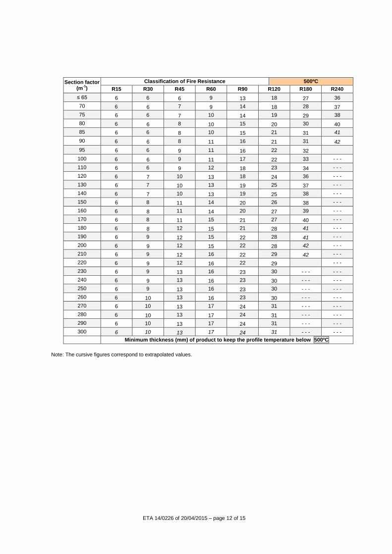
ETA 14/0226 of 20/04/2015 – page 12 of 15
Section factor
(m-1)
Classification of Fire Resistance 500ºC
R15 R30 R45 R60 R90 R120 R180 R240
≤ 65 6 6 6 9 13 18 27 36
70 6 6 7 9 14 18 28 37
75 6 6 7 10 14 19 29 38
80 6 6 8 10 15 20 30 40
85 6 6 8 10 15 21 31 41
90 6 6 8 11 16 21 31 42
95 6 6 9 11 16 22 32
100 6 6 9 11 17 22 33 - - -
110 6 6 9 12 18 23 34 - - -
120 6 7 10 13 18 24 36 - - -
130 6 7 10 13 19 25 37 - - -
140 6 7 10 13 19 25 38 - - -
150 6 8 11 14 20 26 38 - - -
160 6 8 11 14 20 27 39 - - -
170 6 8 11 15 21 27 40 - - -
180 6 8 12 15 21 28 41 - - -
190 6 9 12 15 22 28 41 - - -
200 6 9 12 15 22 28 42 - - -
210 6 9 12 16 22 29 42 - - -
220 6 9 12 16 22 29 - - -
230 6 9 13 16 23 30 - - - - - -
240 6 9 13 16 23 30 - - - - - -
250 6 9 13 16 23 30 - - - - - -
260 6 10 13 16 23 30 - - - - - -
270 6 10 13 17 24 31 - - - - - -
280 6 10 13 17 24 31 - - - - - -
290 6 10 13 17 24 31 - - - - - -
300 6 10 13 17 24 31 - - - - - -
Minimum thickness (mm) of product to keep the profile temperature below 500ºC
Note: The cursive figures correspond to extrapolated values.
ETA 14/0226 of 20/04/2015 – page 13 of 15
Section factor
(m-1)
Classification of Fire Resistance 550ºC
R15 R30 R45 R60 R90 R120 R180 R240
≤ 65 6 6 6 7 12 16 24 33
70 6 6 6 8 12 17 25 34
75 6 6 6 8 13 17 26 35
80 6 6 7 9 13 18 27 36
85 6 6 7 9 14 19 28 38
90 6 6 7 10 14 19 29 39
95 6 6 7 10 15 20 30 40
100 6 6 8 10 15 20 30 41
110 6 6 8 11 16 21 32 42
120 6 6 9 11 17 22 33
130 6 6 9 12 17 23 34 - - -
140 6 7 9 12 18 24 35 - - -
150 6 7 10 13 19 24 36 - - -
160 6 7 10 13 19 25 37 - - -
170 6 7 10 13 19 25 37 - - -
180 6 8 11 14 20 26 38 - - -
190 6 8 11 14 20 26 39 - - -
200 6 8 11 14 20 27 39 - - -
210 6 8 11 14 21 27 40 - - -
220 6 8 11 15 21 27 40 - - -
230 6 8 12 15 21 28 41 - - -
240 6 9 12 15 22 28 41 - - -
250 6 9 12 15 22 28 42 - - -
260 6 9 12 15 22 29 42 - - -
270 6 9 12 16 22 29 42 - - -
280 6 9 12 16 22 29 - - -
290 6 9 12 16 23 29 - - - - - -
300 6 9 13 16 23 30 - - - - - -
Minimum thickness (mm) of product to keep the profile temperature below 550ºC
. Note: The cursive figures correspond to extrapolated values.
ETA 14/0226 of 20/04/2015 – page 14 of 15
Section factor (m
-1)
Classification of Fire Resistance 600ºC
R15 R30 R45 R60 R90 R120 R180 R240
≤ 65 6 6 6 6 10 14 22 30
70 6 6 6 7 11 15 23 31
75 6 6 6 7 12 16 24 33
80 6 6 6 8 12 16 25 34
85 6 6 6 8 13 17 26 35
90 6 6 6 9 13 18 27 36
95 6 6 7 9 14 18 28 37
100 6 6 7 9 14 19 28 38
110 6 6 7 10 15 20 30 40
120 6 6 8 10 15 21 31 41
130 6 6 8 11 16 21 32 42
140 6 6 9 11 17 22 33
150 6 6 9 12 17 23 34 - - -
160 6 6 9 12 18 23 35 - - -
170 6 7 9 12 18 24 35 - - -
180 6 7 10 13 18 24 36 - - -
190 6 7 10 13 19 25 37 - - -
200 6 7 10 13 19 25 37 - - -
210 6 7 10 13 19 26 38 - - -
220 6 8 11 14 20 26 38 - - -
230 6 8 11 14 20 26 39 - - -
240 6 8 11 14 20 27 39 - - -
250 6 8 11 14 21 27 39 - - -
260 6 8 11 14 21 27 40 - - -
270 6 8 11 15 21 27 40 - - -
280 6 8 12 15 21 28 41 - - -
290 6 8 12 15 21 28 41 - - -
300 6 8 12 15 22 28 41 - - -
Minimum thickness (mm) of product to keep the profile temperature below 600ºC
Note: The cursive figures correspond to extrapolated values.
ETA 14/0226 of 20/04/2015 – page 15 of 15
Section factor (m
-1)
Classification of Fire Resistance 650ºC
R15 R30 R45 R60 R90 R120 R180 R240
≤ 65 6 6 6 6 9 13 20 28
70 6 6 6 6 10 14 21 29
75 6 6 6 6 10 14 22 30
80 6 6 6 7 11 15 23 31
85 6 6 6 7 11 16 24 32
90 6 6 6 8 12 16 25 33
95 6 6 6 8 12 17 26 34
100 6 6 6 8 13 17 26 35
110 6 6 6 9 14 18 28 37
120 6 6 7 9 14 19 29 39
130 6 6 7 10 15 20 30 40
140 6 6 8 10 15 21 31 41
150 6 6 8 11 16 21 32 42
160 6 6 8 11 16 22 33
170 6 6 9 11 17 22 33 - - -
180 6 6 9 12 17 23 34 - - -
190 6 6 9 12 18 23 35 - - -
200 6 7 9 12 18 24 35 - - -
210 6 7 10 13 18 24 36 - - -
220 6 7 10 13 19 24 36 - - -
230 6 7 10 13 19 25 37 - - -
240 6 7 10 13 19 25 37 - - -
250 6 7 10 13 19 25 38 - - -
260 6 7 10 14 20 26 38 - - -
270 6 8 11 14 20 26 38 - - -
280 6 8 11 14 20 26 39 - - -
290 6 8 11 14 20 26 39 - - -
300 6 8 11 14 20 27 39 - - -
Minimum thickness (mm) of product to keep the profile temperature below 650ºC
The evaluation results within which the product can be used are:
Section Factor between 65 m-1
and 300 m-1
Protection thicknesses assessed between 6 mm and 42 mm.
Critical temperature of 650 ºC In the same way, the evaluation results are only applicable to:
“I” and “H” section profiles
Those profiles of different type of section to the previous ones must be assessed expressly, according to the indications shown on ANNEX B of the ENV 13381-4:2005.
Other grades of steel in accordance to EN 10025 and EN 10113 Columns and beams with 3 or 4 faces exposed.