ETA-Danmark A/S Göteborg Plads 1 DK-2150 Nordhavn Tel. +45 72 24 59 00 Fax +45 72 24 59 04 Internet www.etadanmark.dk Authorised and notified according to Article 29 of the Regulation (EU) No 305/2011 of the European Parliament and of the Council of 9 March 2011 MEMBER OF EOTA European Technical Assessment ETA-17/0554 of 06/07/2017 I General Part Technical Assessment Body issuing the ETA and designated according to Article 29 of the Regulation (EU) No 305/2011: ETA-Danmark A/S Trade name of the construction product: Simpson Strong-Tie Joist Connectors See type numbers in section II.1 of the ETA Product family to which the above construction product belongs: Three-dimensional nailing plate (timber-to-timber joist connector) Manufacturer: SIMPSON STRONG-TIE Int. Ltd For local branch refer to www.strongtie.eu Manufacturing plant: SIMPSON STRONG-TIE Manufacturing facilities This European Technical Assessment contains: 74 pages including 4 annexes which form an integral part of the document This European Technical Assessment is issued in accordance with Regulation (EU) No 305/2011, on the basis of: Guideline for European Technical Approval (ETAG) No. 015 Three Dimensional Nailing Plates, April 2013, used as European Assessment Document (EAD). This version replaces: ETA-04/0042 issued on 2012-07-16 and expiring on 2017-07-15
Transcript
ETA-Danmark A/S Göteborg Plads 1 DK-2150 Nordhavn Tel. +45 72 24 59 00 Fax +45 72 24 59 04 Internet www.etadanmark.dk
Authorised and notified according to Article 29 of the Regulation (EU) No 305/2011 of the European Parliament and of the Council of 9 March 2011
MEMBER OF EOTA
European Technical Assessment ETA-17/0554 of 06/07/2017
I General Part
Technical Assessment Body issuing the ETA and designated according to Article 29
of the Regulation (EU) No 305/2011: ETA-Danmark A/S
Trade name of the construction
product:
Simpson Strong-Tie Joist Connectors See type numbers in section II.1 of the ETA
Page 2 of 74 of European Technical Assessment no. ETA-17/0554, issued on 2017-07-06
2
II SPECIFIC PART OF THE EUROPEAN TECHNICAL ASSESSMENT 5
1 Technical description of product and intended use 5
2 Specification of the intended use in accordance with the applicable EAD 5
3 Characteristics of product and assessment 7
4 Assessment and verification of constancy of performance (AVCP) 10
5 Technical details necessary for the implementation of the AVCP system, as foreseen in the applicable EAD 10
ANNEX A REVISION HISTORY 11
ANNEX B TYPICAL INSTALLATIONS 12
B1 Typical installation 12
ANNEX C BASIS OF DESIGN 14
C0 Symbols used in the ETA 14
C1 Definition of Force Directions 14
C3 Fastener Specification and Capacities 15
C4 Design Formula where appropriate 21
ANNEX D PRODUCT DEFINITION AND CAPACITIES 23
D1 Connector type IT 24
D2 Connector type ITT 26
D3 Connector type ITSE 28
D4 Connector type MIT 30
D5 Connector type LBV, B, BI and HB 32
D6 Connector type IU 34
D7 Connector type IUT 36
D8 Connector type IUS 38
D9 Connector type IUSE 40
D10 Connector type MIU 43
D11 Connector type HU 45
D12 Connector type U 48
D13 Connector type LUS, HUS 50
Page 3 of 74 of European Technical Assessment no. ETA-17/0554, issued on 2017-07-06
3
D14 Connector type ITB 52
D15 Connector type ITBS 54
D16 Connector type HITB 56
D17 Connector type IUB 58
D18 Connector type IUBS 60
D19 Connector type HIUB 62
D19 Connector type ZS 64
D20 Connector type IUQ 65
D21 Connector type HIUQ 66
D22 Connector type IUC 67
D23 Connector type THM 69
D24 Connector type LIB 71
D25 Connector type LITB 73
Page 4 of 74 of European Technical Assessment no. ETA-17/0554, issued on 2017-07-06
4
Translations of this European Technical Assessment in
other languages shall fully correspond to the original
issued document and should be identified as such.
Communication of this European Technical Assessment, including transmission by electronic means, shall be in full (excepted the confidential Annex(es) referred to above). However, partial reproduction may be made, with the written consent of the issuing Technical Assessment Body. Any partial reproduction has to be identified as such.
Page 5 of 74 of European Technical Assessment no. ETA-17/0554, issued on 2017-07-06
5
II SPECIFIC PART OF THE
EUROPEAN TECHNICAL
ASSESSMENT
1 Technical description of product and
intended use
Technical description of the product This ETA covers the following joist connector types: IT, ITT, MIT, LBV, B, BI, HB, ITSE, IU, IUT, IUS, MIU, HU, U, LUS, HUS, IUSE, ITB, HITB, ITBS, IUB, HIUB, IUBS, IUQ, HIUQ, IUC, THM, ZS, LIB, LITB.
Simpson Strong-Tie, IT, ITT, MIT, LBV, B, BI, HB, ITSE, LITB Top Flange Connectors are one-piece non-welded three-dimensional nailing plates, top-flange supported timber-to-timber connectors. Additionally, the connectors can be welded to a steel header. The LITB connector can also be installed on to a Timber Nailer header. Simpson Strong-Tie IU, IUT, IUS, MIU, HU, U, IUSE and IUC, LIB Face Fix Connectors are one-piece, non-welded three-dimensional nailing plates, face-fix timber-to-timber connectors. Simpson Strong-Tie LUS, HUS and THM Face Fix Connectors are one-piece, non-welded three-dimensional nailing plates, face-fix timber-to-timber joist to truss connectors. Simpson Strong-Tie ITB, ITBS, HITB, HIUB and IUBS Connectors are non-welded three-dimensional nailing plates for timber-to-timber connectors, including I-joists, metal web floor trusses and solid timber joists. The ITB, HITB, IUB and HIUB Connectors are one-piece, and the ITBS and IUBS Connectors are two-piece adjustable angle joist connectors. Simpson Strong-Tie IUQ and HIUQ Face Fix Connectors are non-welded three-dimensional nailing plates, face-fix timber-to-timber joist to SIP panel connectors. Simpson Strong-Tie ZS Clips are non-welded three-dimensional nailing plates for use with I-joists or solid sawn timbers used as noggins between joists to support floor decks or partitions.
The timber elements are fixed together with a range of fasteners. Typical examples are shown in Annexes and typical installations shown in Annex B, Figure 1.
The connectors are made from zinc-coated steel in accordance with EN 10346:2009 (named “Steel ref 1” in the rest of the document) or ASTM A653 (named “Steel ref 2”) and stainless steel in accordance with EN 10088-2:2005 (named “Steel ref 3”), grade 1.4401 or 1.4404 with a minimum characteristic 0.2% yield stress of 240 MPa, a minimum 1.0% yield stress of 270 MPa and a minimum ultimate strength of 530 MPa, and are available in a range of sizes. Material, dimensions and
nails positions are detailed in Annex D and typical installations are detailed in Annex B. By default all the products are made out of this material except when specified. All joist connectors can also be produced from stainless steel number 1.4401, 1.4404, 1.4521, 1.4301 or 1.4509 according to EN 10088-2 or a stainless steel with a minimum characteristic 0.2% yield stress of 240 MPa, a minimum 1.0% yield stress of 270 MPa and a minimum ultimate tensile strength of 530 MPa If no name is clearly specified, product variant made with stainless steel have generally the same name with a S (as Stainless) at the end.
2 Specification of the intended use in
accordance with the applicable EAD
The joist connectors are intended for use in making structural end grain to side-grain joints in timber structures, as a connection between a wood-based joist and a solid-timber or wood-based header, (type IT, ITT, MIT, LBV, B, BI, HB, ITSE can also be used with a steel header), where requirements for mechanical resistance and stability and safety in use in the sense of the Basic Works Requirements 1 and 4 of Regulation (EU) 305/2011 shall be fulfilled. The joist connectors can be installed as connections between wood based members such as:
Structural solid timber classified to C16-C40 according to EN 338 / EN 14081
Glulam classified to GL24-GL36 according to EN 1194 / EN 14080
LVL according to EN 14374
I-beams with backer blocks on both sides of the web in the header and web stiffeners in the joist
Plywood according to EN 636 The connectors are for use in timber structures subject to the dry, internal conditions defined by service classes 1 and 2 of EN 1995-1-1:2004 + A1:2008 (Eurocode 5) and for joints subject to static or quasi-static loading. Annex C defines the directions of forces and also states the formulas for the characteristic load-carrying capacities of the joist connector connections. The design of the connections shall be in accordance with Eurocode 5 or a similar national Timber Code. The joist hangers are intended for use for connections subject to static or quasi static loading. The scope of the hangers regarding resistance to corrosion shall be defined according to national provisions that apply at the installation site considering environmental conditions and in conjunction with the admissible service conditions according to EN 1995-1-1 and the admissible corrosivity category as described and defined in EN ISO 12944-2. The provisions made in this European Technical
Page 6 of 74 of European Technical Assessment no. ETA-17/0554, issued on 2017-07-06
6
Assessment are based on an assumed intended working life for the three-dimensional nailing plate 50 years. The indications given on the working life cannot be interpreted as a guarantee given by the producer or Assessment Body, but are to be regarded only as a means for selecting the appropriate product in relation to the expected economically reasonable working life of the works.
Page 7 of 74 of European Technical Assessment no. ETA-17/0554, issued on 2017-07-06
7
3 Characteristics of product and assessment
Characteristic
Assessment of characteristic
3.1 Mechanical resistance and stability*) (BWR1)
Characteristic load-carrying capacity
See Annex D
Stiffness
No performance assessed (NPA)
Ductility in cyclic testing
No performance Assessed (NPA)
3.2 Safety in case of fire (BWR2)
Reaction to fire
The connectors are made from steel classified as Euroclass A1 in accordance with Commission Delegated Regulation 2016/364, EN 13501-1 and EC decision 96/603/EC, amended by EC Decision 2000/605/EC
3.3 Hygiene, health and the environment (BWR3)
Influence on air quality
The product specification has been compared with the dangerous substances detailed in Council Directive 76/769/EEC (as amended) and listed on the database established on the EC construction website to verify that it does not contain such substances above the acceptable limits.
3.7 Sustainable use of natural resources (BWR7)
No performance assessed (NPA)
3.8 General aspects related to the performance of the
product
The connectors have been assessed as having satisfactory durability and serviceability when used in timber structures using the timber species (including timbers preserved with organic solvent, boron diffusion and related preservatives) described in Eurocode 5 and subject to the dry, internal conditions defined by service classes 1 and 2.
Identification
Each connector bears the manufacturer’s identification mark and the product type. The CE Marking appears on the packaging. See Annex D
*) See additional information in section 3.9 – 3.12.
Page 8 of 74 of European Technical Assessment no. ETA-17/0554, issued on 2017-07-06
8
3.9 Methods of verification
Safety principles and partial factors The characteristic load-carrying capacities are based on the characteristic values of the nail connections and the joist connectors. To obtain design values the capacities have to be divided by different partial factors for the material properties, the nail connection in addition multiplied with the coefficient kmod. According to EN 1990 (Eurocode – Basis of design) paragraph 6.3.5 the design value of load-carrying capacity may be determined by reducing the characteristic values of the load-carrying capacity with different partial factors.
3.10 Mechanical resistance and stability See Annex C for characteristic load-carrying capacities of the joist connectors. The characteristic capacities of the joist connectors are determined by calculation assisted by testing or only testing as described in the EOTA Guideline 015 clause 5.1.2. They should be used for designs in accordance with Eurocode 5 or a similar national Timber Code. The design models allow the use of fasteners described in the table in Annex C3: The characteristic load-carrying capacities of the products shall be calculated in accordance with the manufacturer’s design code, extracts of which are given in Annex C4. The design code has been derived in accordance with ETAG 015 and Eurocode 5. The calculated values should be used for designs in accordance with Eurocode 5 or a similar national Timber Code. These values are based on the assumption that there is a maximum gap of 3 mm between the timber members, the members are laterally restrained and wane is not present in the timber at the joint. The hangers shall be used with the fasteners specified in Annex C3. No performance has been determined in relation to the joint’s stiffness properties - to be used for the analysis of the serviceability limit state. No performance has been determined in relation to ductility of a joint under cyclic testing. The contribution to the performance of structures in seismic zones, therefore, has not been assessed.
3.11 Aspects related to the performance of the
product 3.11.1 Corrosion protection in service class 1 and 2. In accordance with ETAG 015 the joist hanger have a zinc coating weight of min Z275. The steel employed is S250 GD with min Z275 according to EN 10346:2009.
3.11.2 Corrosion protection in service class 3. In accordance with Eurocode 5 the joist connectors are made from stainless steel number 1.4401, 1.4404, 1.4521, 1.4301 or 1.4509 according to EN 10088-2 or a stainless steel with a minimum characteristic 0.2% yield stress of 240 MPa, a minimum 1.0% yield stress of 270 MPa and a minimum ultimate tensile strength of 530 MPa. The nails or screws shall be produced from stainless steel. Joist hangers coated with hot dip galvanisation can also be used in service class 3 according to Eurocode 5
3.12 General aspects related to the use of the product Simpson Strong-Tie joist hangers types IT, ITT, MIT, LBV, B, BI, HB, ITSE, IU, IUT, IUS, MIU, HU, U, LUS, HUS, IUSE, ITB, HITB, ITBS, IUB, HIUB, IUBS, IUQ, HIUQ, IUC, THM, ZS, LIB, LITB are manufactured in accordance with the provisions of this European Technical Assessment using the manufacturing processes as identified in the inspection of the plant by the notified inspection body and laid down in the technical documentation. A connector (three-dimensional nailing plate) is deemed fit for its intended use provided:
- the connector capacity is calculated in accordance with the manufacturer’s literature
- joints are designed in accordance with Eurocode 5 or an appropriate national code, under the responsibility of an engineer experienced in timber structures
- verifiable calculation, notes and drawings are prepared taking account of the loads to be resisted
- the requirements detailed in part II, section 1, of this ETA, relating to the timber members being joined are taken into account, for example, lateral restraint and wane
- joints are designed for the specified fasteners and grade or type of joist and header
- the actual end bearing capacity of the joist (end grain member) to be used with the connector is checked by the designer of the joist to ensure it is not less than the connector capacity and, if necessary, a connector with a larger end bearing capacity substituted to suit. The end bearing capacity of I-joists with solid sawn timber flanges shall be based on the full connector seat bearing area and the appropriate characteristic stress perpendicular to grain for the particular grade of timber. For I-joists with LVL flanges, the joist bearing area shall be taken as 80% of the full connector seat bearing area.
The assessment of the joint has been made under the following assumptions:
- installation is in accordance with the manufacturer’s
- specifications and drawings prepared for that purpose, and the appropriate tools are used
- the specified fasteners and grade or type of joist and
Page 9 of 74 of European Technical Assessment no. ETA-17/0554, issued on 2017-07-06
9
- header are used - the requirements relating to the timber members
being joined are taken into account, e.g.: lateral restraint and wane
- the maximum gap of 3 mm (see Annex B Figure 2)
- between the joist and the header assumed in the - assessment is not exceeded.
Page 10 of 74 of European Technical Assessment no. ETA-17/0554, issued on 2017-07-06
4 Assessment and verification of constancy of
performance (AVCP)
4.1 AVCP system According to the decision 97/638/EC of the European Commission1, as amended, the system(s) of assessment and verification of constancy of performance (see Annex V to Regulation (EU) No 305/2011) is 2+.
5 Technical details necessary for the
implementation of the AVCP system, as
foreseen in the applicable EAD
Technical details necessary for the implementation of the AVCP system are laid down in the control plan deposited at ETA-Danmark prior to CE marking
Issued in Copenhagen on 2017-07-06 by
Thomas Bruun Manager, ETA-Danmark
Page 11 of 74 of European Technical Assessment no. ETA-17/0554, issued on 2017-07-06
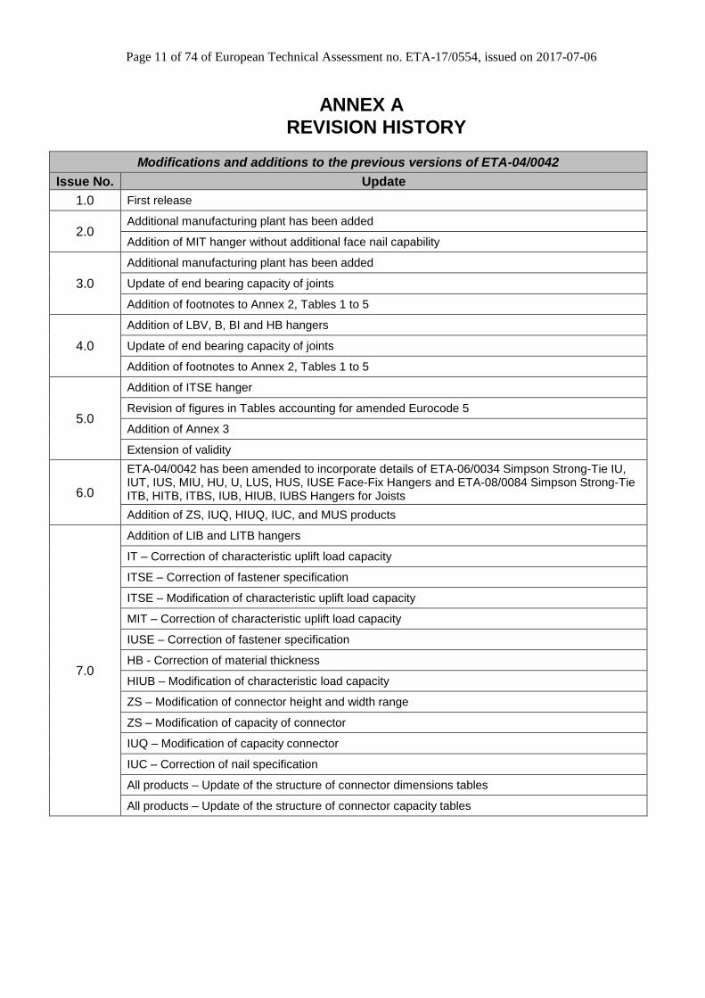
ANNEX A
REVISION HISTORY
Modifications and additions to the previous versions of ETA-04/0042
Issue No. Update
1.0 First release
2.0 Additional manufacturing plant has been added
Addition of MIT hanger without additional face nail capability
3.0
Additional manufacturing plant has been added
Update of end bearing capacity of joints
Addition of footnotes to Annex 2, Tables 1 to 5
4.0
Addition of LBV, B, BI and HB hangers
Update of end bearing capacity of joints
Addition of footnotes to Annex 2, Tables 1 to 5
5.0
Addition of ITSE hanger
Revision of figures in Tables accounting for amended Eurocode 5
Addition of Annex 3
Extension of validity
6.0
ETA-04/0042 has been amended to incorporate details of ETA-06/0034 Simpson Strong-Tie IU, IUT, IUS, MIU, HU, U, LUS, HUS, IUSE Face-Fix Hangers and ETA-08/0084 Simpson Strong-Tie ITB, HITB, ITBS, IUB, HIUB, IUBS Hangers for Joists
Addition of ZS, IUQ, HIUQ, IUC, and MUS products
7.0
Addition of LIB and LITB hangers
IT – Correction of characteristic uplift load capacity
ITSE – Correction of fastener specification
ITSE – Modification of characteristic uplift load capacity
MIT – Correction of characteristic uplift load capacity
IUSE – Correction of fastener specification
HB - Correction of material thickness
HIUB – Modification of characteristic load capacity
ZS – Modification of connector height and width range
ZS – Modification of capacity of connector
IUQ – Modification of capacity connector
IUC – Correction of nail specification
All products – Update of the structure of connector dimensions tables
All products – Update of the structure of connector capacity tables
Page 12 of 74 of European Technical Assessment no. ETA-17/0554, issued on 2017-07-06
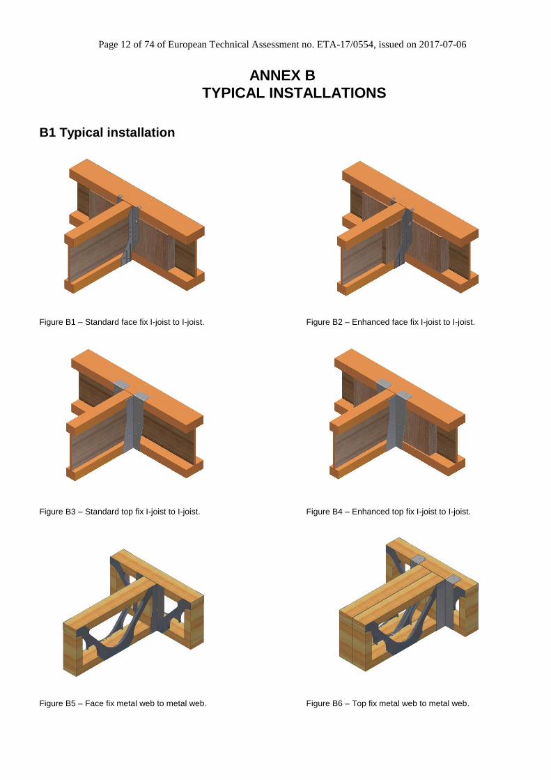
ANNEX B
TYPICAL INSTALLATIONS
B1 Typical installation
Figure B1 – Standard face fix I-joist to I-joist. Figure B2 – Enhanced face fix I-joist to I-joist.
Figure B3 – Standard top fix I-joist to I-joist. Figure B4 – Enhanced top fix I-joist to I-joist.
Figure B5 – Face fix metal web to metal web. Figure B6 – Top fix metal web to metal web.
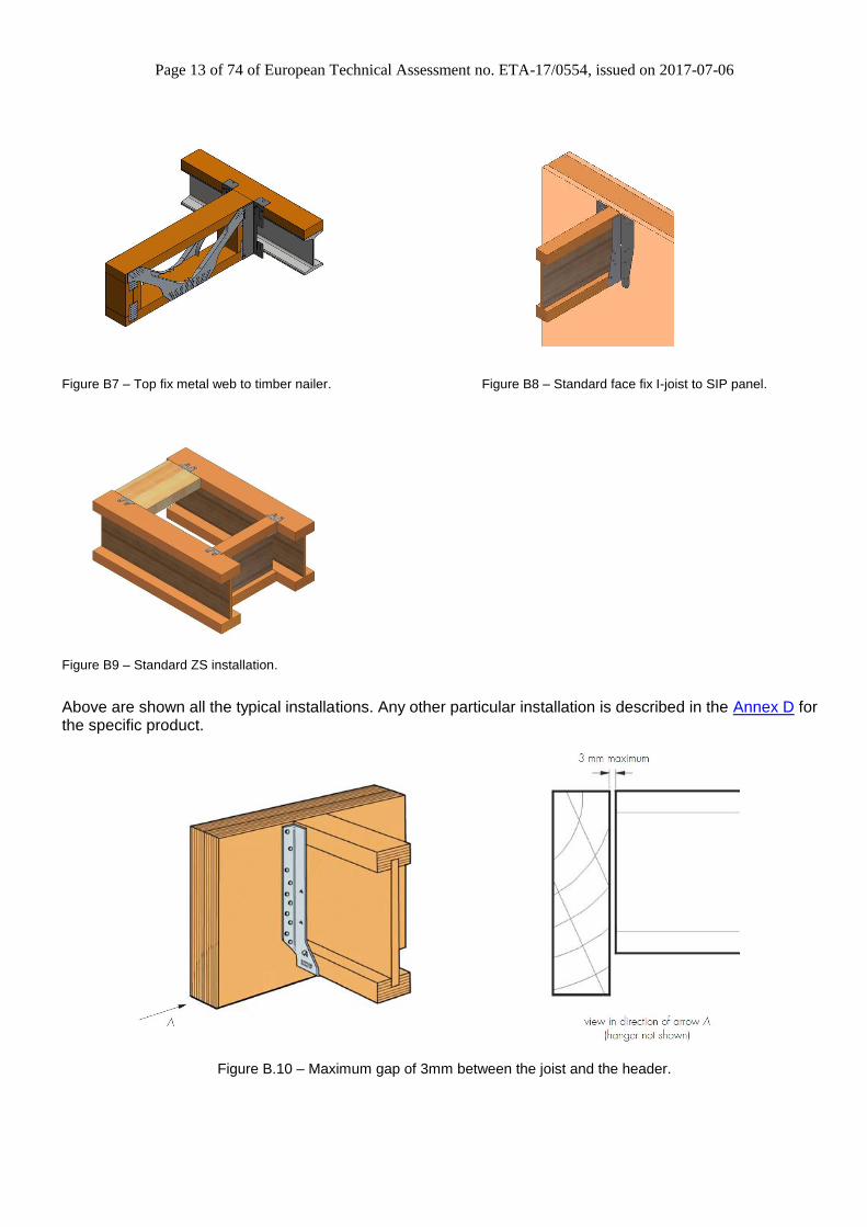
Page 13 of 74 of European Technical Assessment no. ETA-17/0554, issued on 2017-07-06
Figure B7 – Top fix metal web to timber nailer. Figure B8 – Standard face fix I-joist to SIP panel.
Figure B9 – Standard ZS installation.
Above are shown all the typical installations. Any other particular installation is described in the Annex D for the specific product.
Figure B.10 – Maximum gap of 3mm between the joist and the header.
Page 14 of 74 of European Technical Assessment no. ETA-17/0554, issued on 2017-07-06
ANNEX C
BASIS OF DESIGN
C0 Symbols used in the ETA
For the purpose of this ETA, the following symbols apply.
a Lever arm between centre of compression zone and centre of the header nails effective in tension
e Eccentricity of loads, equals distance from centre of seat to face of header.
For HU and HUS connectors the eccentricity can be reduced by calculating the minimum bearing areas Deff required to achieve the joist capacity and using half this value as the eccentricity.
Fv,Rk,j Lateral load-carrying capacity of the side/joist nails (N)
Fv,Rk,h Lateral load-carrying capacity of the header nails (N)
Fax,Rk,h Axial load-carrying capacity of the header nails (N)
fu Tensile strength of hanger steel (N/mm2)
n Factor dependent on nail type:
n = 2 for ring shank nails (CNA)
n = 100 for smooth (plain or square twisted nails)
nj Number of effective joist nails
nh Number of effective header nails
ρk Characteristic density of header or joist material (kg/m3)
t Thickness of side flanges (mm)
S Minimum width of connector side flanges (mm)
C1 Definition of Force Directions
To determine the characteristic capacities for the timber-to-timber connectors, the load has been applied in F1 and F2 directions as shown in Figure C.1.
Figure C.1 – Definition of force directions.
Page 15 of 74 of European Technical Assessment no. ETA-17/0554, issued on 2017-07-06
C3 Fastener Specification and Capacities
Fastener types and sizes CNA connector nails and CSA connector screws according to ETA-04/0013.
Nail type Nail size
(mm)
Finish / Material According to ETA-
04/0013 annex A
drawing 1 and 2
Diameter Length
CNA Connector nail 3.7 50 Electroplated zinc
CNA Connector nail 4.0 35 Electroplated zinc
CNA Connector nail 4.0 40 Electroplated zinc
CNA Connector nail 4.0 50 Electroplated zinc
CNA Connector nail 4.2 35 Electroplated zinc
CNA Connector nail 4.2 50 Electroplated zinc
CNA Connector nail 4.0 40 Stainless steel
CNA Connector nail 4.0 50 Stainless steel
CNA Connector nail 4.0 60 Stainless steel
CSA Connector screw 4.0 30 Electroplated zinc
CSA Connector screw 5.0 50 Electroplated zinc
Other fasteners according to EN 14592.
Fasteners
According to EN 14592
Nail size
(mm) Finish / Material
Diameter Length
Annular ring shank nail 3.7 40 Electroplated zinc
Square Twist nail 3.75 30 Hot-dip galvanized/
Sheradized/ Electroplated
Smooth shank nail 3.75 75 Hot-dip galvanized
Round Wire nail 4.0 100 Hot-dip galvanized
SDS coach screw 6.2 63 Stainless steel
Page 16 of 74 of European Technical Assessment no. ETA-17/0554, issued on 2017-07-06
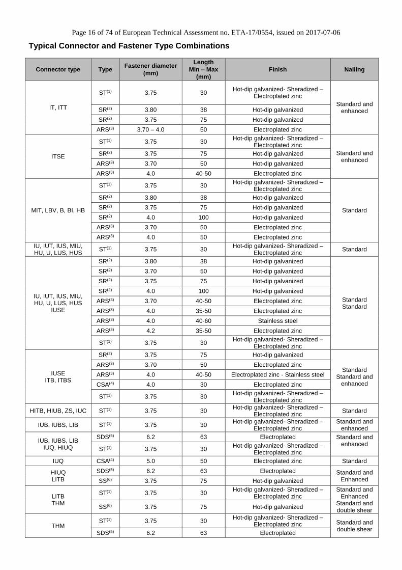
Typical Connector and Fastener Type Combinations
Connector type Type Fastener diameter
(mm)
Length
Min – Max
(mm)
Finish Nailing
IT, ITT
ST(1) 3.75 30 Hot-dip galvanized- Sheradized –
Electroplated zinc
Standard and enhanced SR(2) 3.80 38 Hot-dip galvanized
SDS(5) 6.2 63 Electroplated Standard and Enhanced SS(6) 3.75 75 Hot-dip galvanized
LITB THM
ST(1) 3.75 30 Hot-dip galvanized- Sheradized –
Electroplated zinc Standard and
Enhanced Standard and double shear
SS(6) 3.75 75 Hot-dip galvanized
THM ST(1) 3.75 30
Hot-dip galvanized- Sheradized –Electroplated zinc Standard and
double shear SDS(5) 6.2 63 Electroplated
Page 17 of 74 of European Technical Assessment no. ETA-17/0554, issued on 2017-07-06
(1)Square Twist nail (2)Round Wire nail (3)Annular Ring Shank nail (4)Connector screw (5)SDS Coach screw (6)Smooth Shank nail
Page 18 of 74 of European Technical Assessment no. ETA-17/0554, issued on 2017-07-06
Nail Capacity Tables Capacities of 3.75 x 30 mm Square Twist Nails
Nail
Reference
Nail
Shape
Side
Length or
Diameter
(mm)
Nail
Length
(mm)
Wire
Tensile
Strength
(mm)
Plate
Thickness
(mm)
Timber
Grade
Timber
Char.
Density
(kg/m3)
Fax,Rk
(N)
Fv,Rk
(N)
3.75 x 30 ST
Square 3.40 30 600 1.2
C16 310 188 899
C18 320 201 925
C20 330 213 951
C22 340 226 978
C24 350 240 1004
C27 370 268 1057
C30 380 283 1083
SCL 480 451 1353
3.75 x 30 ST
Square 3.40 30 600 1.5
C16 310 186 893
C18 320 198 919
C20 330 211 945
C22 340 224 970
C24 350 237 996
C27 370 265 1049
C30 380 280 1075
SCL 480 447 1342
3.75 x 30 ST
Square 3.40 30 600 2.0
C16 310 183 882
C18 320 195 908
C20 330 207 933
C22 340 220 959
C24 350 233 984
C27 370 261 1035
C30 380 275 1061
SCL 480 439 1324
Page 19 of 74 of European Technical Assessment no. ETA-17/0554, issued on 2017-07-06
Capacities of Round Wire Nails
Nail
Reference
Nail
Shape
Side
Length or
Diameter
(mm)
Nail
Length
(mm)
Wire
Tensile
Strength
(mm)
Plate
Thickness
(mm)
Timber
Grade
Timber
Char.
Density
(kg/m3)
Fax,Rk
(N)
Fv,Rk
(N)
3.8 x 38 SR
Round 3.80 38 600 1.2
C16 310 269 1145
C18 320 286 1180
C20 330 305 1216
C22 340 323 1251
C24 350 343 1280
C27 370 383 1337
C30 380 404 1365
SCL 480 644 1653
3.75 x 75 SR
Round 3.75 75 600 1.2
C16 310 532 1309
C18 320 567 1336
C20 330 603 1364
C22 340 640 1391
C24 350 678 1419
C27 370 758 1474
C30 380 799 1502
SCL 480 1275 1782
4.0 x 100 SR
Round 4.00 100 600 1.2
C16 310 760 1498
C18 320 809 1531
C20 330 861 1565
C22 340 914 1598
C24 350 968 1632
C27 370 1082 1699
C30 380 1141 1733
SCL 480 1821 2083
3.8 x 38 SR
Round 3.80 38 600 1.5
C16 310 267 1137
C18 320 284 1172
C20 330 302 1208
C22 340 321 1244
C24 350 340 1275
C27 370 380 1332
C30 380 401 1360
SCL 480 639 1647
3.75 x 75 SR
Round 3.75 75 600 1.5
C16 310 530 1308
C18 320 564 1336
C20 330 600 1363
C22 340 637 1391
C24 350 675 1418
C27 370 755 1473
C30 380 796 1501
SCL 480 1270 1781
Page 20 of 74 of European Technical Assessment no. ETA-17/0554, issued on 2017-07-06
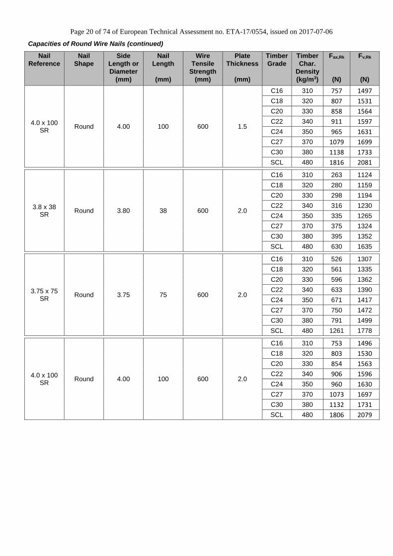
Capacities of Round Wire Nails (continued)
Nail
Reference
Nail
Shape
Side
Length or
Diameter
(mm)
Nail
Length
(mm)
Wire
Tensile
Strength
(mm)
Plate
Thickness
(mm)
Timber
Grade
Timber
Char.
Density
(kg/m3)
Fax,Rk
(N)
Fv,Rk
(N)
4.0 x 100 SR
Round 4.00 100 600 1.5
C16 310 757 1497
C18 320 807 1531
C20 330 858 1564
C22 340 911 1597
C24 350 965 1631
C27 370 1079 1699
C30 380 1138 1733
SCL 480 1816 2081
3.8 x 38 SR
Round 3.80 38 600 2.0
C16 310 263 1124
C18 320 280 1159
C20 330 298 1194
C22 340 316 1230
C24 350 335 1265
C27 370 375 1324
C30 380 395 1352
SCL 480 630 1635
3.75 x 75 SR
Round 3.75 75 600 2.0
C16 310 526 1307
C18 320 561 1335
C20 330 596 1362
C22 340 633 1390
C24 350 671 1417
C27 370 750 1472
C30 380 791 1499
SCL 480 1261 1778
4.0 x 100 SR
Round 4.00 100 600 2.0
C16 310 753 1496
C18 320 803 1530
C20 330 854 1563
C22 340 906 1596
C24 350 960 1630
C27 370 1073 1697
C30 380 1132 1731
SCL 480 1806 2079
Page 21 of 74 of European Technical Assessment no. ETA-17/0554, issued on 2017-07-06
C4 Design Formula where appropriate
Nail capacities The nail capacities are calculated as follows, and have been validated against connector test data:
smooth nails (plain or square twisted) — as specified in relevant tables given in Annex C3. These may have an efficiency factor applied as part of the design method validation and are only for use in conjunction with the connectors described in this ETA.
CNA ring-shank nails — calculated as described in ETA-04/0013
other ring-shank nails — calculated as described in Eurocode 5.
Top fix connectors (Design Model and performance tables) The characteristic load-carrying capacities for the IT, ITT, MIT, LBV, B, BI, HB and ITSE connectors are given in the tables in Annex D which have been derived in accordance with ETAG 015:2002. They should be used for designs in accordance with Eurocode 5. These values are based on the assumption that there is a maximum gap of 3 mm between the timber members, the members are laterally restrained and wane is not present in the timber at the joint. Capacities for intermediate widths can be interpolated. Connector capacity is independent of the connector height. The connectors shall only be used with the fasteners specified in the relevant table in Annex C. The performance of the fasteners have been determined in accordance with either ETA04/0013 or Eurocode 5 (see also Annex D), using an ultimate tensile strength for the wire used for the production of the nails of 600 MPa.
Face fix connector (Design model and listed variables) The design method used to determine the characteristic load-carrying capacities for the connectors has been validated by the ‘calculation assisted by testing’ method as defined in ETAG 015 and is detailed in the technical report entitled ‘Approval for IU, IUT, IUS, MIU, HU, U, LUS, HUS and IUSE’, which has been substantiated by ETA Danmark as part of the ETA approval process. Summary of design model, to be used in conjunction with the values listed in Annex D: Design — Vertical down load capacity (F1) The load is transferred from the supported member to the supporting member by:
1. Tension in the lower part of the connector. 2. Load transfer from the connector to the supporting member.
The capacity of the system is the minimum of the above two mechanisms. Capacity = Min. (Ft, Fh) Tension in the lower part of the connector (Ft):
ut ftSF 2
Load transfer from the connector to the supporting member (Fh):
nn
hRkaxh
n
hRkvh
hFna
e
FnF
/1
,,,,
1/1
Design — Vertical up load capacity (F2)
Page 22 of 74 of European Technical Assessment no. ETA-17/0554, issued on 2017-07-06
hRkvhjRkvjuplift FnFnF ,,,, ;min
The connectors shall only be used with the fasteners specified in the relevant table in Annex D. The performance of the fasteners have been determined in accordance with either ETA04/0013 or Eurocode 5 (see also Annex C), using an ultimate tensile strength for the wire used for the production of the nails of 600 MPa.
Other hangers determined by test method (performance tables) The characteristic load-carrying capacities for the connectors IUQ, HIUQ, IUC, IUBS, THM, ZS, IUB, HIUB, ITBS, ITB and HITB LIB, LITB are given in the tables in Annex D which have been derived in accordance with ‘Test Only’ method in accordance with ETAG 015:2002. They should be used for designs in accordance with Eurocode 5. These values are based on the assumption that there is a maximum gap of 3 mm between the timber members, the members are laterally restrained and wane is not present in the timber at the joint. Capacities for intermediate widths can be interpolated. Connector capacity is independent of the connector height. The connectors shall only be used with the fasteners specified in the relevant table in Annex C3. The performance of the fasteners have been determined in accordance with either ETA04/0013 or Eurocode 5 (see also Annex 4), using an ultimate tensile strength for the wire used for the production of the nails of 600 MPa.
Page 23 of 74 of European Technical Assessment no. ETA-17/0554, issued on 2017-07-06
ANNEX D
PRODUCT DEFINITION AND CAPACITIES
Page 24 of 74 of European Technical Assessment no. ETA-17/0554, issued on 2017-07-06
D1 Connector type IT
Product Name Material reference acc.
to clause II-1 Alternative Names
IT Steel ref 1 -
Product dimensions
Item
Product dimensions [mm] Header holes Joist holes
A B
C D E F t
Top Face Pan
hole
6x4
Triangular
inside Ø4 Min Max Min Max Ø4 Ø4 Triangular
inside Ø4
IT 40 91 140 600 51 51 35 59 1.2 4 2 2 2 2
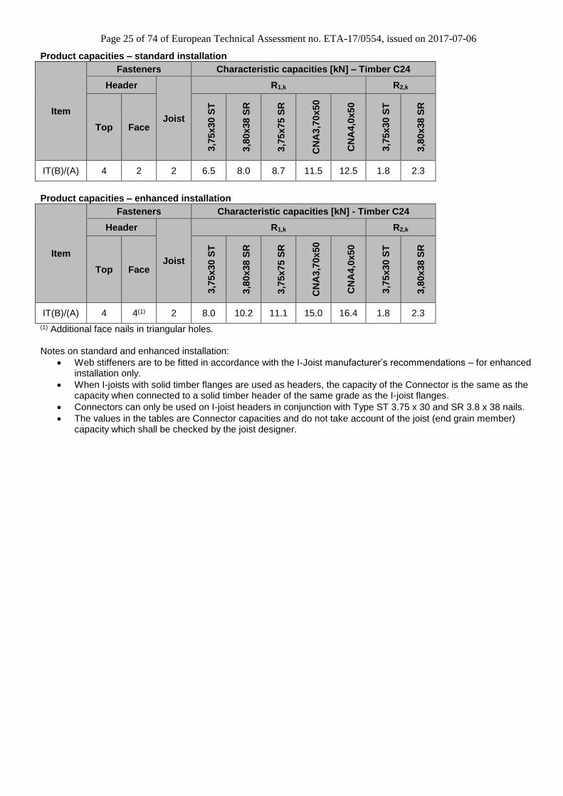
Page 25 of 74 of European Technical Assessment no. ETA-17/0554, issued on 2017-07-06
Web stiffeners are to be fitted in accordance with the I-Joist manufacturer’s recommendations – for enhanced installation only.
When I-joists with solid timber flanges are used as headers, the capacity of the Connector is the same as the capacity when connected to a solid timber header of the same grade as the I-joist flanges.
Connectors can only be used on I-joist headers in conjunction with Type ST 3.75 x 30 and SR 3.8 x 38 nails.
The values in the tables are Connector capacities and do not take account of the joist (end grain member) capacity which shall be checked by the joist designer.
Page 26 of 74 of European Technical Assessment no. ETA-17/0554, issued on 2017-07-06
D2 Connector type ITT
Product Name Material reference acc.
to clause II-1 Alternative Names
ITT Steel ref 1 – Steel ref 2 -
Product dimensions
Item
Product dimensions [mm] Header holes Joist holes
A B
C D E F t
Top Face
Ø4x5,5 Triangular
inside Ø4 Min Max Min Max Ø4 Ø4 Triangular
inside Ø4
ITT 40 91 140 600 51 51 35 58 1.2 4 2 2 2 2
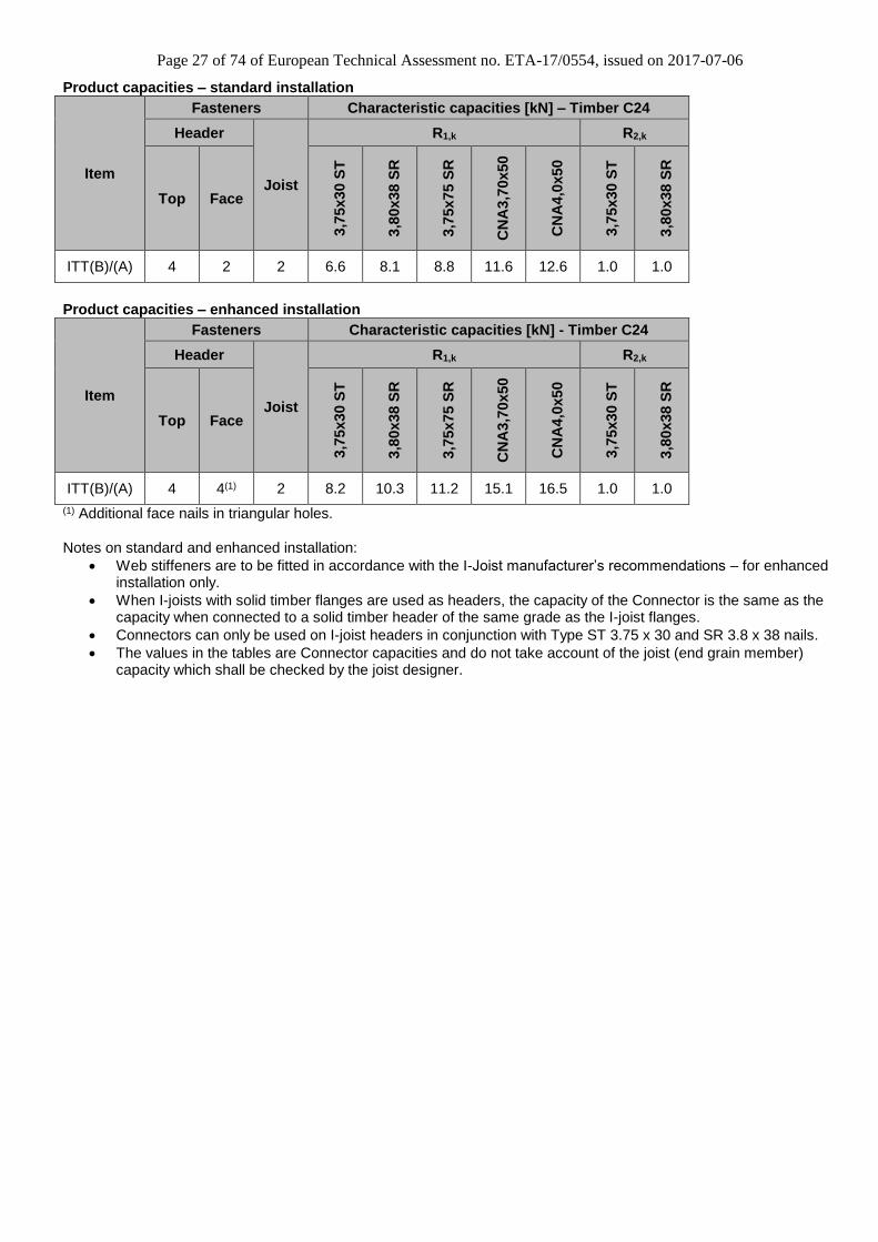
Page 27 of 74 of European Technical Assessment no. ETA-17/0554, issued on 2017-07-06
Web stiffeners are to be fitted in accordance with the I-Joist manufacturer’s recommendations – for enhanced installation only.
When I-joists with solid timber flanges are used as headers, the capacity of the Connector is the same as the capacity when connected to a solid timber header of the same grade as the I-joist flanges.
Connectors can only be used on I-joist headers in conjunction with Type ST 3.75 x 30 and SR 3.8 x 38 nails.
The values in the tables are Connector capacities and do not take account of the joist (end grain member) capacity which shall be checked by the joist designer.
Page 28 of 74 of European Technical Assessment no. ETA-17/0554, issued on 2017-07-06
D3 Connector type ITSE
Product Name Material reference acc.
to clause II-1 Alternative Names
ITSE Steel ref 1 -
Product dimensions
Item
Product dimensions [mm] Header holes Joist holes
A B
C D E F t
Top Face
Ø4x6
Triangular
inside
Ø4.1 Min Max Min Max Ø4 Ø4
Triangular
inside
Ø4.1
ITSE 40 100 140 600 51 51 34 58 1.2 4 2 2 2 6
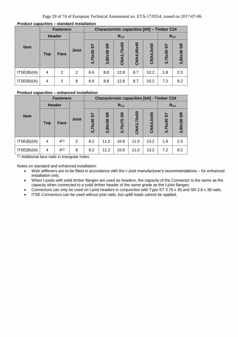
Page 29 of 74 of European Technical Assessment no. ETA-17/0554, issued on 2017-07-06
Web stiffeners are to be fitted in accordance with the I-Joist manufacturer’s recommendations – for enhanced installation only.
When I-joists with solid timber flanges are used as headers, the capacity of the Connector is the same as the capacity when connected to a solid timber header of the same grade as the I-joist flanges.
Connectors can only be used on I-joist headers in conjunction with Type ST 3.75 x 30 and SR 3.8 x 38 nails.
ITSE Connectors can be used without joist nails, but uplift loads cannot be applied.
Page 30 of 74 of European Technical Assessment no. ETA-17/0554, issued on 2017-07-06
D4 Connector type MIT
Product Name Material reference acc.
to clause II-1 Alternative Names
MIT Steel ref 2 -
Product dimensions
Item
Product dimensions [mm] Header holes Joist holes
A B
C D E F t
Top Face
Ø4x6 Triangular
inside Ø4 Min Max Min Max Ø4 Ø4
MIT 40 125 140 600 63.5 64 59 70 1.5 4 4 2 2
Page 31 of 74 of European Technical Assessment no. ETA-17/0554, issued on 2017-07-06
Web stiffeners are to be fitted in accordance with the I-Joist manufacturer’s recommendations – for enhanced installation only.
When I-joists with solid timber flanges are used as headers, the capacity of the Connector is the same as the capacity when connected to a solid timber header of the same grade as the I-joist flanges.
Connectors can only be used on I-joist headers in conjunction with Type ST 3.75 x 30 and SR 3.8 x 38 nails.
The values in the tables are Connector capacities and do not take account of the joist (end grain member)
capacity which shall be checked by the joist designer.
Page 32 of 74 of European Technical Assessment no. ETA-17/0554, issued on 2017-07-06
Web stiffeners are to be fitted in accordance with the I-Joist manufacturer’s recommendations.
When I-joists with solid timber flanges are used as headers, the capacity of the Connector is the same as the capacity when connected to a solid timber header of the same grade as the I-joist flanges.
Connectors can only be used on I-joist headers in conjunction with Type ST 3.75 x 30 and SR 3.8 x 38 nails.
The values in the tables are Connector capacities and do not take account of the joist (end grain member)
capacity which shall be checked by the joist designer.
Page 34 of 74 of European Technical Assessment no. ETA-17/0554, issued on 2017-07-06
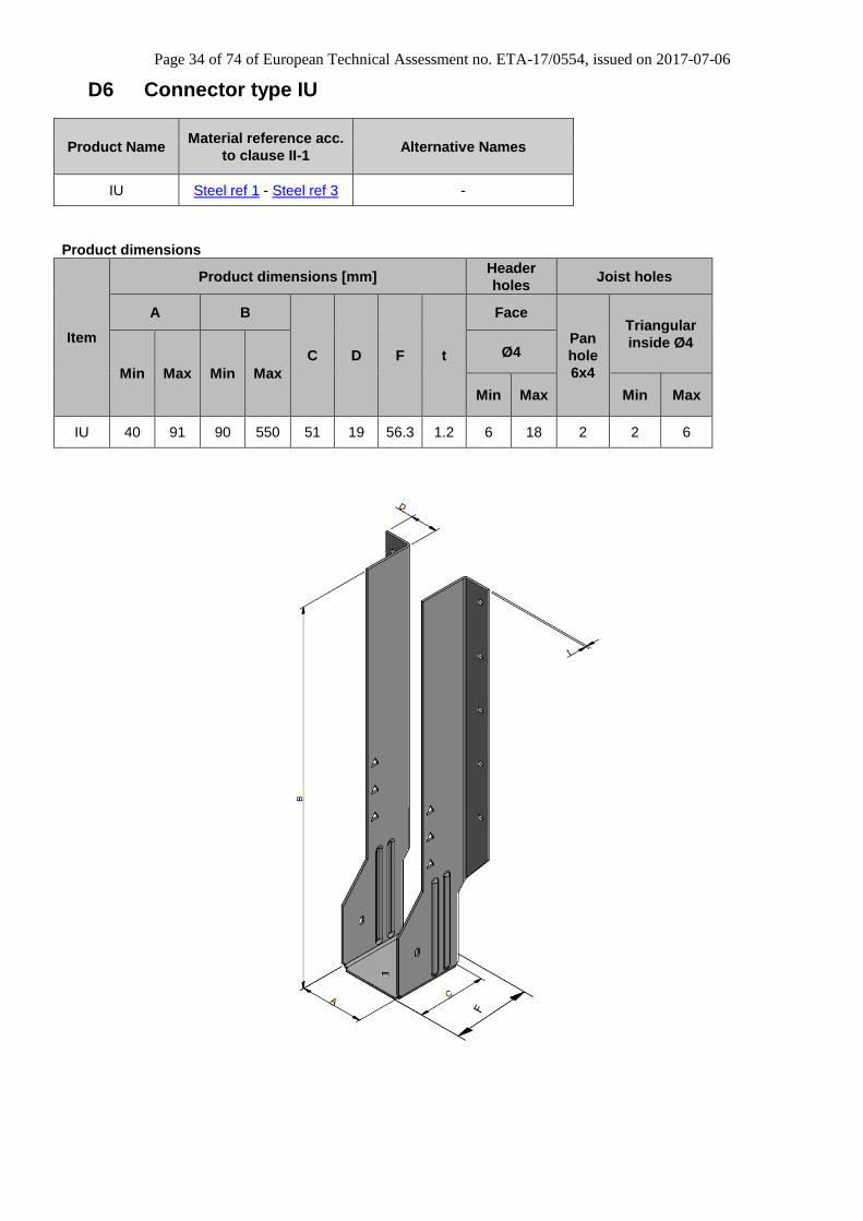
D6 Connector type IU
Product Name Material reference acc.
to clause II-1 Alternative Names
IU Steel ref 1 - Steel ref 3 -
Product dimensions
Item
Product dimensions [mm] Header
holes Joist holes
A B
C D F t
Face
Pan
hole
6x4
Triangular
inside Ø4
Min Max Min Max
Ø4
Min Max Min Max
IU 40 91 90 550 51 19 56.3 1.2 6 18 2 2 6
Page 35 of 74 of European Technical Assessment no. ETA-17/0554, issued on 2017-07-06
Product capacities
Notes:
Web stiffeners are to be fitted in accordance with the I-Joist manufacturer’s recommendations – for enhanced installation only.
Page 46 of 74 of European Technical Assessment no. ETA-17/0554, issued on 2017-07-06
Product capacities
Hanger Size [mm]
Item
Lever
arm Ecc No of No of Side Steel Steel
A B C
a e Header Joist Flange Thickness Strength
(mm) (mm) nail nail S t fu (MPa)
40 78 57 HU26 43 28 4 2 49 2 262
79 78 63 HU24-2 43 32 4 2 49 2 262
79 137 63 HU26-2 72 32 8 4 49 2 262
79 137 63 HU26-2 72 32 12 6 49 2 262
180 150 63 HU480/180 78 32 10 4 49 2 270
180 150 63 HU480/180 78 32 14 6 49 2 270
90 173 63 HU48 90 32 10 4 49 2 262
90 173 63 HU48 90 32 14 6 49 2 262
180 175 63 HU530/180 93 32 14 6 49 2 270
79 178 63 HU28-2 93 32 10 4 49 2 262
79 178 57 HU28-2 93 32 14 6 49 2 262
38 198 63 HU210 95 32 8 4 49 2 262
46 170 63 HU7 100 32 12 4 49 2 262
46 170 63 HU7 100 32 16 8 49 2 262
135 196 63 HU5.31/9 115 32 14 6 49 2 262
135 196 63 HU5.31/9 115 32 18 8 49 2 262
90 219 63 HU410 115 32 14 6 49 2 262
90 219 63 HU410 115 32 18 10 49 2 262
79 224 63 HU210-2 115 32 14 6 49 2 262
79 224 63 HU210-2 115 32 18 10 49 2 262
181 231 63 HU410-2 120 32 14 6 49 2 262
181 231 63 HU410-2 120 32 18 8 49 2 262
70 229 63 HU2.75/10 129 32 14 6 49 2 262
70 229 63 HU2.75/10 129 32 18 10 49 2 262
46 235 63 HU9 135 32 18 6 49 2 262
46 235 63 HU9 135 32 24 10 49 2 262
135 240 63 HU5.31/11 135 32 16 6 49 2 262
135 240 63 HU5.31/11 135 32 22 8 49 2 262
90 262 63 HU412 135 32 16 6 49 2 262
90 262 63 HU412 135 32 22 10 49 2 262
79 268 63 HU212-2 138 32 16 6 49 2 262
79 268 63 HU212-2 138 32 22 10 49 2 262
181 282 63 HU412-2 145 32 16 6 49 2 262
181 282 63 HU412-2 145 32 22 8 49 2 262
70 273 63 HU2.75/12 151 32 16 6 49 2 262
70 273 63 HU2.75/12 151 32 22 10 49 2 262
46 279 63 HU11 155 32 22 6 49 2 262
46 279 63 HU11 155 32 30 10 49 2 262
135 297 63 HU5.31/14 163 32 18 8 49 2 262
135 297 63 HU5.31/14 163 32 24 12 49 2 262
135 324 63 HU5.31/16 177 32 20 8 49 2 262
Page 47 of 74 of European Technical Assessment no. ETA-17/0554, issued on 2017-07-06
Hanger Size [mm]
Item
Lever
arm Ecc No of No of Side Steel Steel
A B C
a e Header Joist Flange Thickness Strength
(mm) (mm) nail nail S t fu (MPa)
135 324 63 HU5.31/16 177 32 26 12 49 2 262
70 330 63 HU2.75/14 169 32 18 8 49 2 262
70 330 63 HU2.75/14 169 32 24 14 49 2 262
90 346 63 HU416 177 32 20 8 49 2 262
90 346 63 HU416 177 32 26 12 49 2 262
181 352 63 HU414-2 180 32 20 8 49 2 262
181 352 63 HU414-2 180 32 26 12 49 2 262
70 357 63 HU2.75/16 182 32 20 8 49 2 262
70 357 63 HU2.75/16 182 32 26 14 49 2 262
46 346 63 HU14 189 32 28 8 49 2 262
46 346 63 HU14 189 32 36 14 49 2 262
Notes:
Web stiffeners are to be fitted in accordance with the I-Joist manufacturer’s recommendations.
For nail capacities refer to Annex C3.
Page 48 of 74 of European Technical Assessment no. ETA-17/0554, issued on 2017-07-06
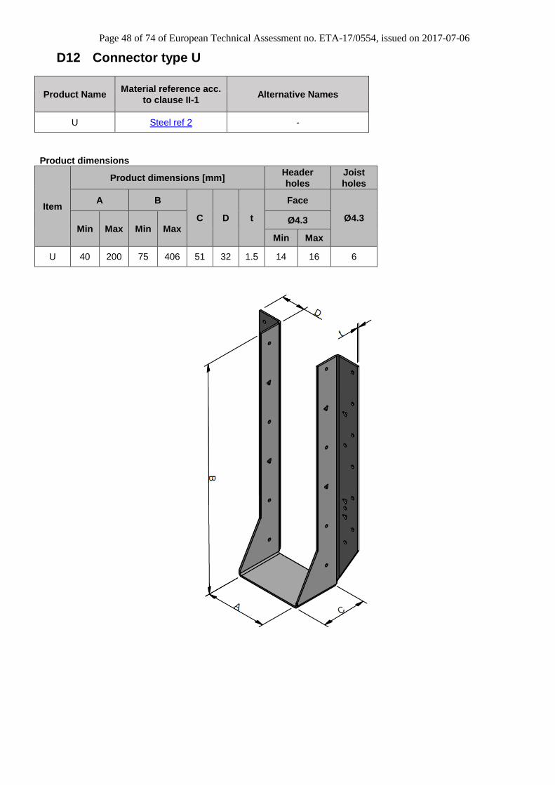
D12 Connector type U
Product Name Material reference acc.
to clause II-1 Alternative Names
U Steel ref 2 -
Product dimensions
Item
Product dimensions [mm] Header
holes
Joist
holes
A B
C D t
Face
Ø4.3 Min Max Min Max
Ø4.3
Min Max
U 40 200 75 406 51 32 1.5 14 16 6
Page 49 of 74 of European Technical Assessment no. ETA-17/0554, issued on 2017-07-06
Product capacities
Hanger Size [mm]
Item
Lever
arm Ecc No of No of Side Steel Steel
A B C
a e Header Joist Flange Thickness Strength
(mm) (mm) nail nail S t fu (MPa)
59 228 51 U3510/14 116 25.4 14 6 32 1.5 262
79 216 51 U210-2 116 25.4 14 6 32 1.5 262
90 213 51 U410 116 25.4 14 6 32 1.5 262
62 268 51 U3516/20 128 25.4 16 6 32 1.5 262
90 254 51 U414 128 25.4 16 6 32 1.5 262
120 286 51 U3512-2 128 25.4 16 6 32 1.5 262
Notes:
Web stiffeners are to be fitted in accordance with the I-Joist manufacturer’s recommendations – for enhanced installation only.
For nail capacities refer to Annex C3.
Page 50 of 74 of European Technical Assessment no. ETA-17/0554, issued on 2017-07-06
D13 Connector type LUS, HUS
Product Name Material reference acc.
to clause II-1 Alternative Names
LUS Steel ref 1– Steel ref 3 -
HUS Steel ref 1– Steel ref 3 -
Product dimensions
Item
Product dimensions [mm] Header Holes Joist holes
A B
C D t Ø4 Ø4 Pan Hole Min Max Min Max
LUS 38 50 51 96 51 25.6 1.0 10 6
HUS 38 50 76 100 75 28.6 1.2 30 10
Page 51 of 74 of European Technical Assessment no. ETA-17/0554, issued on 2017-07-06
Product capacities – Standard installation – Timber to Timber
Item
Hanger Size [mm] Lever
arm
a
[mm]
Ecc
e
[mm]
No of
header
nails
nh
No of
joist
nails
nj
Side
flange
S
[mm]
Steel
thickness
t
[mm]
Steel
strength
fu
[N/mm2] A B C
LUS230/38 38 241 30 66 15 10 6 33 1.0 270
LUS230/44 44 302 30 63 15 10 6 33 1.0 270
LUS230/50 50 302 30 60 15 10 6 33 1.0 270
HUS230/38 38 241 30 66 15 10 6 33 1.2 270
HUS230/44 44 302 30 63 15 10 6 33 1.2 270
HUS230/50 50 302 30 60 15 10 6 33 1.2 270
Note:
For nail capacities refer to Annex C3.
Page 52 of 74 of European Technical Assessment no. ETA-17/0554, issued on 2017-07-06
D14 Connector type ITB
Product Name Material reference acc.
to clause II-1 Alternative Names
ITB Steel ref 1 -
Product dimensions
Item
Product dimensions [mm] Header holes Joist holes
A B
C D E t
Top &
Bottom Face
Ø6x4 Triangular
inside Ø4 Min Max Min Max Ø4 Ø4
Triangular
inside Ø4
ITB 40 100 195 302 51 55 35 1.2 6 8 6 2 4
Page 53 of 74 of European Technical Assessment no. ETA-17/0554, issued on 2017-07-06
Product capacities – Standard installation
Item Type
Fasteners
Characteristic
capacities [kN]
- Timber C24
Header Joist
R1,k R2,k Top &
Bottom Type Face Type Qty Type
ITB(B)/(A) < 35 mm
LVL flange 4 3,75x30 ST 8 3,75x30 ST 2 3,75x30 ST 10.8 1.1
ITB(B)/(A) ≥ 35 mm
LVL flange 4 3,75x30 ST 8 3,75x30 ST 2 3,75x30 ST 9.2 1.2
ITB(B)/(A) ≥ 45 mm
C24 flange 4 3,75x30 ST 8 3,75x30 ST 2 3,75x30 ST 6.7 1.1
Product capacities - Enhanced installation
Item Type
Fasteners
Characteristic
capacities [kN]
- Timber C24
Header Joist
R1,k R2,k Top &
Bottom Type Face Type Qty Type
ITB(B)/(A) < 35 mm
LVL flange 4 3,75x30 ST 14 3,75x30 ST 6 3,75x30 ST 17.4 9.3
ITB(B)/(A) ≥ 35 mm
LVL flange 4 3,75x30 ST 14 3,75x30 ST 6 3,75x30 ST 17.4 7.6
ITB(B)/(A) ≥ 45 mm
C24 flange 4 3,75x30 ST 14 3,75x30 ST 6 3,75x30 ST 17.9 8.0
Note: • Enhanced installation refers to I-joists headers with backer blocks. • Web stiffeners are to be fitted in accordance with the I-Joist manufacturer’s recommendations – for enhanced installation only.
Page 54 of 74 of European Technical Assessment no. ETA-17/0554, issued on 2017-07-06
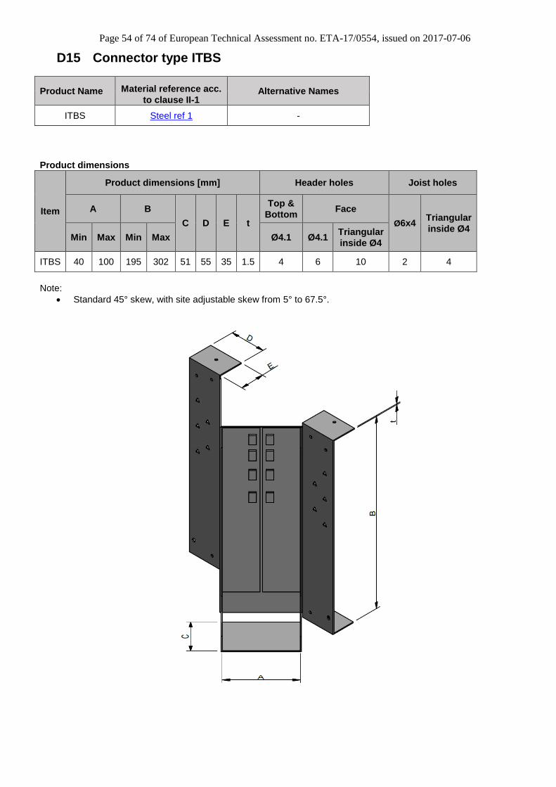
D15 Connector type ITBS
Product Name Material reference acc.
to clause II-1 Alternative Names
ITBS Steel ref 1 -
Product dimensions
Item
Product dimensions [mm] Header holes Joist holes
A B
C D E t
Top &
Bottom Face
Ø6x4 Triangular
inside Ø4 Min Max Min Max Ø4.1 Ø4.1
Triangular
inside Ø4
ITBS 40 100 195 302 51 55 35 1.5 4 6 10 2 4
Note:
Standard 45° skew, with site adjustable skew from 5° to 67.5°.
Page 55 of 74 of European Technical Assessment no. ETA-17/0554, issued on 2017-07-06
Product capacities – Standard installation
Item Type
Fasteners
Characteristic
capacities [kN]
- Timber C24
Header Joist
R1,k R2,k Top &
Bottom Type Face Type Qty Type
ITBS(B)/(A) <35 mm
LVL flange 4 3.75 x 30 ST 8 3.75 x 30 ST 1 3.75 x 30 ST 7.5 1.5
ITBS(B)/(A) ≥35 mm
LVL flange 4 3.75 x 30 ST 8 3.75 x 30 ST 1 3.75 x 30 ST 10.2 1.5
ITBS(B)/(A) ≥45 mm
C24 flange 4 3.75 x 30 ST 8 3.75 x 30 ST 1 3.75 x 30 ST 7.4 1.5
Product capacities - Enhanced installation
Item Type
Fasteners
Characteristic
capacities [kN]
- Timber C24
Header Joist
R1,k R2,k Top &
Bottom Type Face Type Qty Type
ITBS(B)/(A) <35 mm
LVL flange 4 3.75 x 30 ST 18 3.75 x 30 ST 3
3.75 x 30 ST
13.5 1.5
ITBS(B)/(A) ≥35 mm
LVL flange 4 3.75 x 30 ST 18 3.75 x 30 ST 3
3.75 x 30 ST
15.0 1.5
ITBS(B)/(A) ≥45 mm
C24 flange 4 3.75 x 30 ST 18 3.75 x 30 ST 3
3.75 x 30 ST
12.8 1.5
Note: • Enhanced installation refers to I-joists headers with backer blocks. • Web stiffeners are to be fitted in accordance with the I-Joist manufacturer’s recommendations – for enhanced installation only.
Page 56 of 74 of European Technical Assessment no. ETA-17/0554, issued on 2017-07-06
D16 Connector type HITB
Product Name Material reference acc.
to clause II-1 Alternative Names
HITB Steel ref 1 -
Product dimensions
Item
Product dimensions [mm] Header holes Joist holes
A B
C D E t
Top Bottom Face
Ø6x4 Ø4
Min Max Min Max Ø4 Ø4 Ø4 Ø6x4
HITB 40 100 195 302 60 65 180 2 18 2 8 4 2 6
Page 57 of 74 of European Technical Assessment no. ETA-17/0554, issued on 2017-07-06
Product capacities – Standard installation
Note:
• Web stiffeners are to be fitted in accordance with the I-Joist manufacturer’s recommendations.
Item Type
Fasteners
Characteristic
capacities [kN]
- Timber C24
Header Joist
R1,k R2,k Top Type Bottom Type Face Type Qty Type
HITB(B)/(A) < 35 mm
LVL flange 8
3.75 x 30 ST
2 3.75 x 30
ST 12
3.75 x 30 ST
8 3.75 x 30
ST 15.6 11.4
HITB(B)/(A) ≥ 35 mm
LVL flange 8
3.75 x 30 ST
2 3.75 x 30
ST 12
3.75 x 30 ST
8 3.75 x 30
ST 17.5 11.4
HITB(B)/(A) ≥ 45 mm
C24 flange 8
3.75 x 30 ST
2 3.75 x 30
ST 12
3.75 x 30 ST
8 3.75 x 30
ST 19.1 11.1
Page 58 of 74 of European Technical Assessment no. ETA-17/0554, issued on 2017-07-06
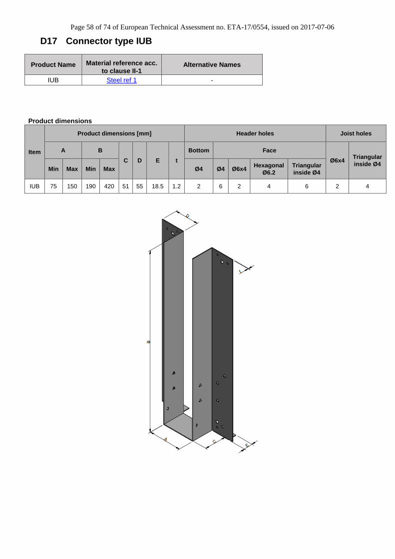
D17 Connector type IUB
Product Name Material reference acc.
to clause II-1 Alternative Names
IUB Steel ref 1 -
Product dimensions
Item
Product dimensions [mm] Header holes Joist holes
A B
C D E t
Bottom Face
Ø6x4 Triangular
inside Ø4 Min Max Min Max Ø4 Ø4 Ø6x4
Hexagonal
Ø6.2
Triangular
inside Ø4
IUB 75 150 190 420 51 55 18.5 1.2 2 6 2 4 6 2 4
Page 59 of 74 of European Technical Assessment no. ETA-17/0554, issued on 2017-07-06
Product capacities – Standard installation
Item
Fasteners Characteristic capacities
[kN] - Timber C24
Header Joist R1,k R2,k
Bottom Type Face Type Qty Type
IUB(B)/(A) 2 3,75x30 ST 8 3,75x30 ST 2 3,75x30 ST 8.1 2.0
Product capacities – Enhanced installation
Item
Fasteners Characteristic capacities
[kN] - Timber C24
Header Joist R1,k R2,k
Bottom Type Face Type Qty Type
IUB(B)/(A) - - 4 SDS 2 3,75x30 ST 13.6 2.0
IUB(B)/(A) - - 4 SDS 6 3,75x30 ST 13.6 6.0
Page 60 of 74 of European Technical Assessment no. ETA-17/0554, issued on 2017-07-06
D18 Connector type IUBS
Product Name Material reference acc.
to clause II-1 Alternative Names
IUBS Steel ref 1 -
Product dimensions
Item
Product dimensions [mm] Header holes Joist holes
A B
C D E t
Bottom Face
Ø4.1 Ø4.1 Ø6x4
Hexagonal
holes
Ø6x4
Triangular
inside Ø4 Ø4
Triangular
inside Ø4 Min Max Min Max
IUBS 75 100 195 295 64 55 35 1.5 2 4 2 4 4 2 6
Note:
Standard 45° skew, with site adjustable skew from 5° to 67.5°.
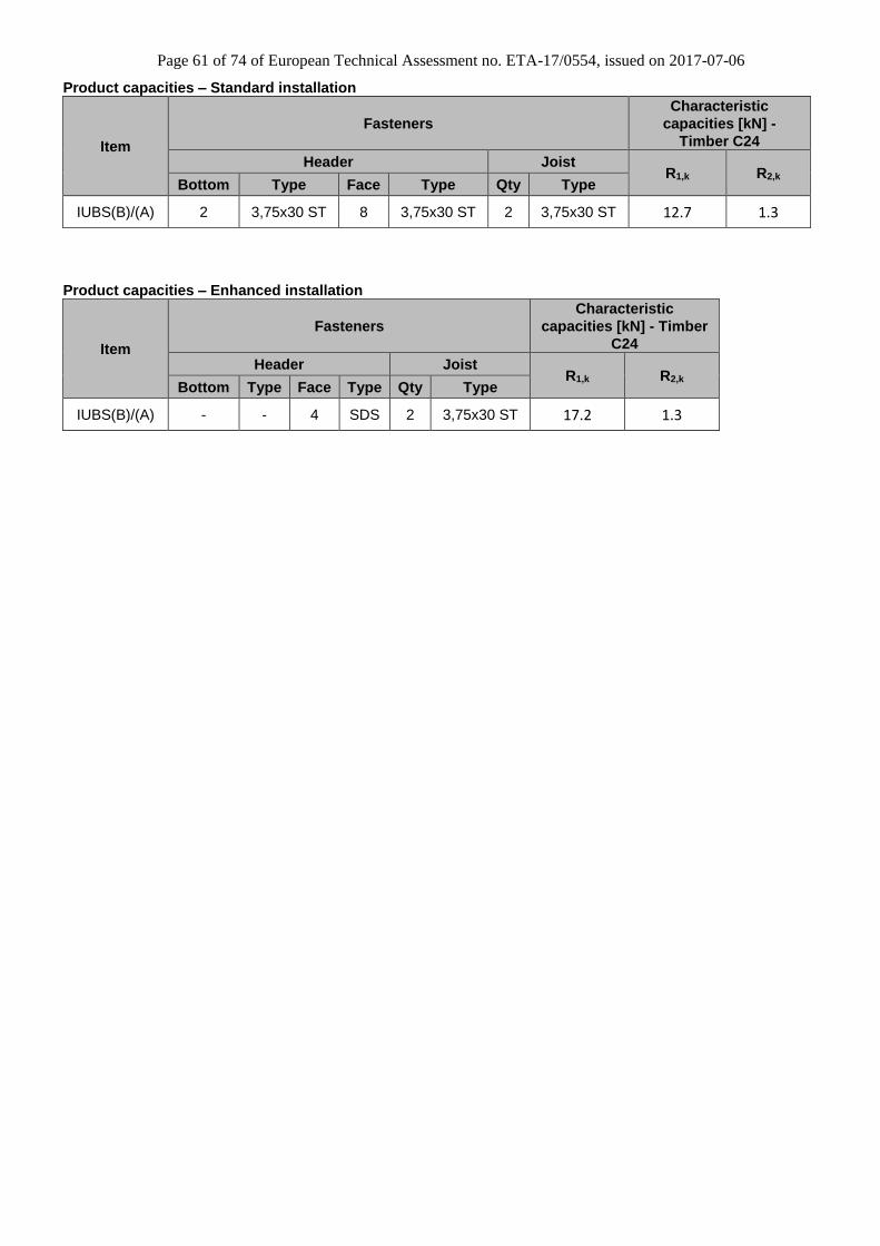
Page 61 of 74 of European Technical Assessment no. ETA-17/0554, issued on 2017-07-06
Product capacities – Standard installation
Item
Fasteners
Characteristic
capacities [kN] -
Timber C24
Header Joist R1,k R2,k
Bottom Type Face Type Qty Type
IUBS(B)/(A) 2 3,75x30 ST 8 3,75x30 ST 2 3,75x30 ST 12.7 1.3
Product capacities – Enhanced installation
Item
Fasteners
Characteristic
capacities [kN] - Timber
C24
Header Joist R1,k R2,k
Bottom Type Face Type Qty Type
IUBS(B)/(A) - - 4 SDS 2 3,75x30 ST 17.2 1.3
Page 62 of 74 of European Technical Assessment no. ETA-17/0554, issued on 2017-07-06
D19 Connector type HIUB
Product Name Material reference acc.
to clause II-1 Alternative Names
HIUB Steel ref 1 -
Product dimensions
Item
Product dimensions [mm] Header holes Joist holes
A B
C D E t
Top Face
Ø4 Ø6x4
Min Max Min Max Ø4 Ø4
HIUB 75 300 202 420 63.5 63.5 63.5 2 6 10 6 2
Page 63 of 74 of European Technical Assessment no. ETA-17/0554, issued on 2017-07-06
Product capacities – Standard installation
Item
Fasteners Characteristic capacities
[kN] - Timber C27/Tr26
Header Joist R1,k R2,k
Top Type Face Type Qty Type
HIUB(B)/(A) 6 3,75x30 ST 10 3,75x30 ST 8 3,75x30 ST 19.2 8.0
Product capacities – Enhanced installation
Item
Fasteners Characteristic capacities
[kN] - Timber C27/Tr26
Header Joist R1,k R2,k
Top Type Face Type Qty Type
HIUB(B)/(A) 6 3,75x30 ST 10 3,75x30 ST 8 3,75x30 ST 23.4 8.0
Note:
For enhanced installation, a timber blocking piece is to be fixed between the top and bottom flanges of Metal Web Floor Trusses.
Page 64 of 74 of European Technical Assessment no. ETA-17/0554, issued on 2017-07-06
Loads given are per noggin – not per Z – Clip. When I-joists with solid timber flanges are used as headers, the capacity of the Connector is the same as the
capacity when connected to a solid timber header of the same grade as the I-joist flanges.
Connectors can only be used on I-joist headers in conjunction with Type ST 3.75 x 30 nails.
The values in the tables are Connector capacities and do not take account of the joist (end grain member) capacity which shall be checked by the joist designer.
Page 65 of 74 of European Technical Assessment no. ETA-17/0554, issued on 2017-07-06
D20 Connector type IUQ
Product Name Material reference
acc. to clause II-1 Alternative Names
IUQ Steel ref 1 -
Product dimensions
Item
Product dimensions [mm] Header holes Joist holes
A B
C D E t Ø4.1 Ø5 Ø6x4 Triangular
inside Ø4
Hexagonal
Holes Ø6x4
Triangular
inside Ø4 Min Max Min Max
IUQ 40 100 190 450 51 55 18.5 1.2 4 4 2 6 4 2 4
Product capacities – Standard installation
Item
Fasteners Characteristic capacities
[kN] - Timber C24
Header Joist R1,k R2,k
Qty Type Qty Type
IUQ(B)/(A) 4 CSA 5.0 x 50 2 3.75 x 30 ST 13.8 2.0
Note:
Web stiffeners are to be fitted in accordance with the I-Joist manufacturer’s recommendations – for enhanced installation only.
Page 66 of 74 of European Technical Assessment no. ETA-17/0554, issued on 2017-07-06
D21 Connector type HIUQ
Product Name Material reference
acc. to clause II-1 Alternative Names
HIUQ Steel ref 1 -
Product Dimensions
Item
Product dimensions [mm] Header Holes Joist holes
A B
C D E t
Hexagonal
Holes
Ø6.2
Ø4.1 Ø6x4
Min Max Min Max
HIUQ 40 300 190 450 63.5 63.5 63.5 2.0 4 6 2
Product capacities – Standard installation
Item
Fasteners Characteristic capacities [kN] -
Timber C24
Header Joist R1,k R2,k
Qty Type Qty Type
HIUQ(B)/(A) 4 SDS 8 3.75 x 30 ST 19.5 2.0
Note:
Web stiffeners are to be fitted in accordance with the I-Joist manufacturer’s recommendations – for enhanced installation only.
Page 67 of 74 of European Technical Assessment no. ETA-17/0554, issued on 2017-07-06
D22 Connector type IUC
Product Name Material reference
acc. to clause II-1 Alternative Names
IUC Steel ref 1 -
Product dimensions
Item
Product dimensions [mm] Header holes Joist holes
A B
C D F t
Ø4
Ø6x4 Triangular
inside Ø4 Min Max Min Max Min Max
IUC 40 100 140 300 51 19 57 1.2 6 14 2 6
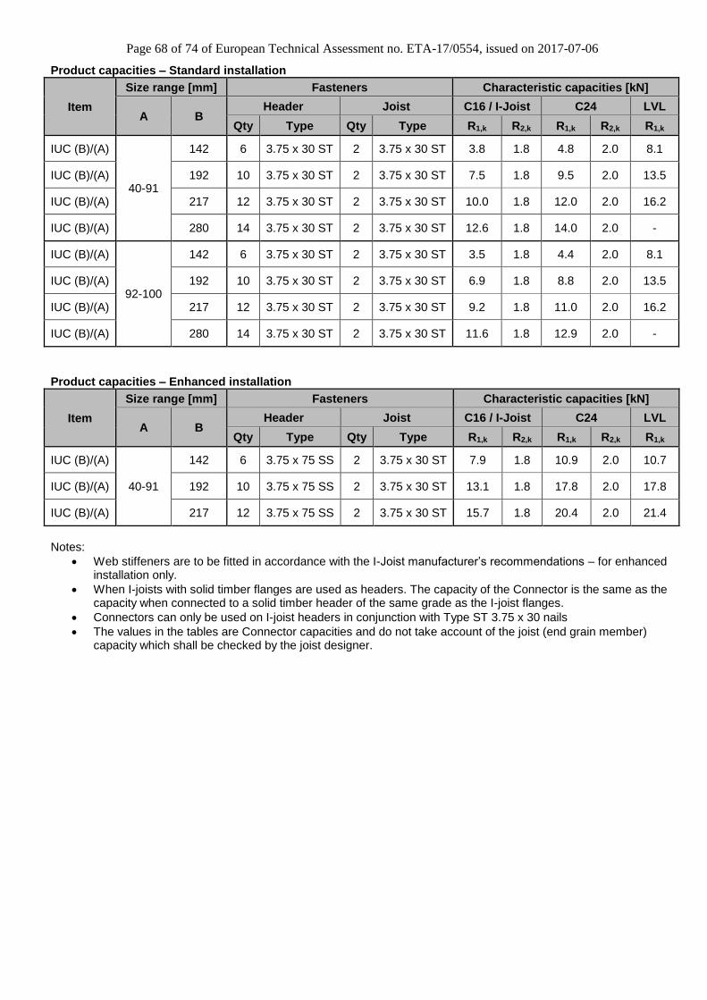
Page 68 of 74 of European Technical Assessment no. ETA-17/0554, issued on 2017-07-06
Product capacities – Standard installation
Item
Size range [mm] Fasteners Characteristic capacities [kN]
A B Header Joist C16 / I-Joist C24 LVL
Qty Type Qty Type R1,k R2,k R1,k R2,k R1,k
IUC (B)/(A)
40-91
142 6 3.75 x 30 ST 2 3.75 x 30 ST 3.8 1.8 4.8 2.0 8.1
IUC (B)/(A) 192 10 3.75 x 30 ST 2 3.75 x 30 ST 7.5 1.8 9.5 2.0 13.5
IUC (B)/(A) 217 12 3.75 x 30 ST 2 3.75 x 30 ST 10.0 1.8 12.0 2.0 16.2
IUC (B)/(A) 280 14 3.75 x 30 ST 2 3.75 x 30 ST 12.6 1.8 14.0 2.0 -
IUC (B)/(A)
92-100
142 6 3.75 x 30 ST 2 3.75 x 30 ST 3.5 1.8 4.4 2.0 8.1
IUC (B)/(A) 192 10 3.75 x 30 ST 2 3.75 x 30 ST 6.9 1.8 8.8 2.0 13.5
IUC (B)/(A) 217 12 3.75 x 30 ST 2 3.75 x 30 ST 9.2 1.8 11.0 2.0 16.2
IUC (B)/(A) 280 14 3.75 x 30 ST 2 3.75 x 30 ST 11.6 1.8 12.9 2.0 -
Product capacities – Enhanced installation
Item
Size range [mm] Fasteners Characteristic capacities [kN]
A B Header Joist C16 / I-Joist C24 LVL
Qty Type Qty Type R1,k R2,k R1,k R2,k R1,k
IUC (B)/(A)
40-91
142 6 3.75 x 75 SS 2 3.75 x 30 ST 7.9 1.8 10.9 2.0 10.7
IUC (B)/(A) 192 10 3.75 x 75 SS 2 3.75 x 30 ST 13.1 1.8 17.8 2.0 17.8
IUC (B)/(A) 217 12 3.75 x 75 SS 2 3.75 x 30 ST 15.7 1.8 20.4 2.0 21.4
Notes:
Web stiffeners are to be fitted in accordance with the I-Joist manufacturer’s recommendations – for enhanced installation only.
When I-joists with solid timber flanges are used as headers. The capacity of the Connector is the same as the capacity when connected to a solid timber header of the same grade as the I-joist flanges.
Connectors can only be used on I-joist headers in conjunction with Type ST 3.75 x 30 nails
The values in the tables are Connector capacities and do not take account of the joist (end grain member) capacity which shall be checked by the joist designer.
Page 69 of 74 of European Technical Assessment no. ETA-17/0554, issued on 2017-07-06
D23 Connector type THM
Product Name Material reference
acc. to clause II-1 Alternative Names
THM Steel ref 1 -
Product dimensions
Item
Product dimensions [mm] Header holes Joist holes
A B
C D t Ø4.1
Hexagonal
holes
Ø6x4
Ø6x4
Min Max Min Max
THM 38 50 90 96 75 42 0.9 10 4 6
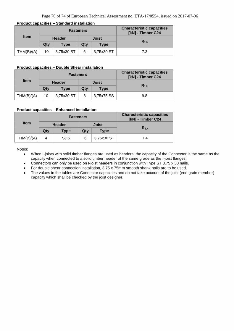
Page 70 of 74 of European Technical Assessment no. ETA-17/0554, issued on 2017-07-06
Product capacities – Standard installation
Item
Fasteners Characteristic capacities
[kN] - Timber C24
Header Joist R1,k
Qty Type Qty Type
THM(B)/(A) 10 3,75x30 ST 6 3,75x30 ST 7.3
Product capacities – Double Shear installation
Item
Fasteners Characteristic capacities
[kN] - Timber C24
Header Joist R1,k
Qty Type Qty Type
THM(B)/(A) 10 3,75x30 ST 6 3,75x75 SS 9.8
Product capacities – Enhanced installation
Item
Fasteners Characteristic capacities
[kN] - Timber C24
Header Joist R1,k
Qty Type Qty Type
THM(B)/(A) 4 SDS 6 3,75x30 ST 7.4
Notes:
When I-joists with solid timber flanges are used as headers, the capacity of the Connector is the same as the capacity when connected to a solid timber header of the same grade as the I-joist flanges.
Connectors can only be used on I-joist headers in conjunction with Type ST 3.75 x 30 nails.
For double shear connection installation, 3.75 x 75mm smooth shank nails are to be used.
The values in the tables are Connector capacities and do not take account of the joist (end grain member) capacity which shall be checked by the joist designer.
Page 71 of 74 of European Technical Assessment no. ETA-17/0554, issued on 2017-07-06
D24 Connector type LIB
Product Name Material reference acc.
to clause II-1 Alternative Names
LIB Steel ref 1 -
Product dimensions
Item
Product dimensions [mm] Header holes Joist holes
A B
C D t
Face
Ø4
Min Max Min Max Ø4 Hexagonal
holes Ø6.4
LIB 40 200 140 420 48.5 48.5 0.9 16 4 4
Page 72 of 74 of European Technical Assessment no. ETA-17/0554, issued on 2017-07-06
Product capacities - Standard installation for I-Joist headers
Item Type
Dimensions [mm] Fasteners
Characteristic
capacities [kN] -
Timber C24
A B Header Joist
R1,k R2,k Qty Type Qty Type
LIB(B)/(A) < 35 mm LVL flange 53 - 61 195 - 300 10 3,75x30 ST 4 3,75x30 ST 5.3 3.4
LIB(B)/(A) ≥ 35 mm LVL flange 40 - 200 190 - 300 10 3,75x30 ST 4 3,75x30 ST 7.4 3.4
LIB(B)/(A) ≥ 45 mm C24 flange 47 - 200 140 - 300 10 3,75x30 ST 4 3,75x30 ST 8.9 3.4
Product capacities - Standard installation for Metal Web headers
Item Type
Dimensions [mm] Fasteners
Characteristic
capacities [kN] -
Timber C24
A B Header Joist
R1,k R2,k Qty Type Qty Type
LIB(B)/(A) Metal Web joists 47 - 200 195 - 420 8 3,75x30 ST 4 3,75x30 ST 6.6 3.4
Product capacities - Enhanced installation for I-Joist headers
Item Type
Dimensions [mm] Fasteners
Characteristic
capacities [kN] -
Timber C24
A B Header Joist
R1,k R2,k Qty Type Qty Type
LIB(B)/(A) < 35 mm LVL flange 53 - 61 195 - 300 14 3,75x30 ST 4 3,75x30 ST 11.2 3.4
LIB(B)/(A) ≥ 35 mm LVL flange 40 - 91 190 - 300 14 3,75x30 ST 4 3,75x30 ST 11.2 3.4
LIB(B)/(A) ≥ 45 mm C24 flange 47 - 100 140 - 300 14 3,75x30 ST 4 3,75x30 ST 13.4 3.4
Product capacities - Enhanced installation for Metal Web headers
Item Type
Dimensions [mm] Fasteners
Characteristic
capacities [kN] -
Timber C24
A B Header Joist
R1,k R2,k Qty Type Qty Type
LIB(B)/(A) Metal Web joists 47 - 100 190 - 420 4 SDS 4 3,75x30 ST 8.4 3.4
Note:
• Standard = Installation without backer blocks
• Enhanced = Installation with backer blocks fitted as per I-Joist manufacturers details
Page 73 of 74 of European Technical Assessment no. ETA-17/0554, issued on 2017-07-06
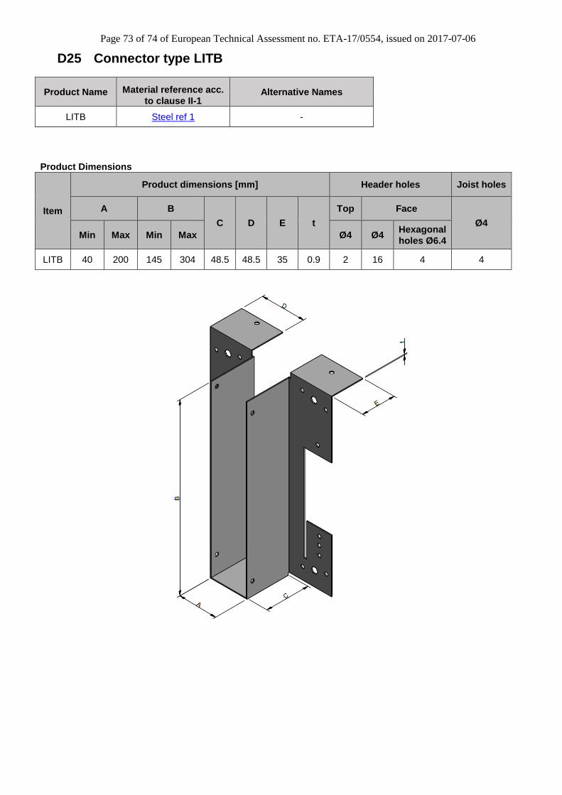
D25 Connector type LITB
Product Name Material reference acc.
to clause II-1 Alternative Names
LITB Steel ref 1 -
Product Dimensions
Item
Product dimensions [mm] Header holes Joist holes
A B
C D E t
Top Face
Ø4
Min Max Min Max Ø4 Ø4 Hexagonal
holes Ø6.4
LITB 40 200 145 304 48.5 48.5 35 0.9 2 16 4 4
Page 74 of 74 of European Technical Assessment no. ETA-17/0554, issued on 2017-07-06
Product capacities - Standard installation for I-Joist headers
Item Type Dimensions [mm]
Fasteners
Characteristic
capacities
[kN] - Timber
C24
Header Joist R1,k R2,k
A B Top Type Face Type Qty Type
LITB(B)/(A) < 35 mm
LVL flange 53 - 61 220 - 300 2
3,75x30 ST
10 3,75x30
ST 4
3,75x30 ST
7.6 3.4
LITB(B)/(A) ≥ 35 mm
LVL flange 40 - 200 195 - 300 2
3,75x30 ST
10 3,75x30
ST 4
3,75x30 ST
8.9 3.4
LITB(B)/(A) ≥ 45 mm
C24 flange 47 - 200 145 - 300 2
3,75x30 ST
10 3,75x30
ST 4
3,75x30 ST
10.1 3.4
Product capacities - Standard installation for Metal Web headers
Item Type Dimensions [mm]
Fasteners
Characteristic
capacities
[kN] - Timber
C24
Header Joist R1,k R2,k
A B Top Type Face Type Qty Type
LITB(B)/(A) Metal Web
joists 47 - 200 195 - 304 2
3,75x30 ST
8 3,75x30
ST 4
3,75x30 ST
11.0 3.4
Product capacities - Standard installation for Timber Nailers
Item Type
Nailer
Depth
[mm]
Hanger
Width
[mm]
Fasteners
Characteristic
capacities
[kN] - Timber
C24
Header Joist R1,k R2,k
Top Type Face Type Qty Type
LITB(B)/(A) Timber Nailer
38 - 50 40 - 96 2 3,75x30
ST 4
3,75x30 ST
4 3,75x30
ST 7.9 3.6
LITB(B)/(A) Timber Nailer
38 - 50 100 2 3,75x30
ST 4
3,75x30 ST
4 3,75x30
ST 9.5 3.6
LITB(B)/(A) Timber Nailer
75 - 100 40 - 100 2 3,75x30
ST 4
3,75x30 ST
4 3,75x30
ST 11.6 3.6
Product capacities - Enhanced installation for I-Joist headers
Item Type Dimensions [mm]
Fasteners
Characteristic
capacities
[kN] - Timber
C24
Header Joist R1,k R2,k
A B Top Type Face Type Qty Type
LITB(B)/(A) < 35 mm
LVL flange 53 - 61 220 - 300 2
3,75x30 ST
16 3,75x30
ST 4
3,75x30 ST
16.1 3.4
LITB(B)/(A) ≥ 35 mm
LVL flange 40 - 91 195 - 300 2
3,75x30 ST
16 3,75x30
ST 4
3,75x30 ST
16.1 3.4
LITB(B)/(A) ≥ 45 mm
C24 flange 47 - 100 145 - 300 2
3,75x30 ST
16 3,75x30
ST 4
3,75x30 ST
17.2 3.4
Note:
• Standard = Installation without backer blocks
• Enhanced = Installation with backer blocks fitted as per I-Joist manufacturers details