INSTITUTO DE CIENCIAS DE LA CONSTRUCCIÓN EDUARDO TORROJA Member of www.eota.eu C/ Serrano Galvache n. 4 28033 Madrid (Spain) Tel.: (34) 91 302 04 40 Fax: (34) 91 302 07 00 [email protected]https://dit.ietcc.csic.es European Technical Assessment ETA 05/0242 of 04/03/2019 English translation prepared by IETcc. Original version in Spanish language General Part Technical Assessment Body issuing the ETA designated according to Art. 29 of Regulation (EU) 305/2011: Instituto de Ciencias de la Construcción Eduardo Torroja (IETcc) Trade name of the construction product: Anchor MTH Anchor MTH-A2 Anchor MTH-A4 Product family to which the construction product belongs: Torque controlled expansion anchor made of galvanised steel or stainless steel of sizes M6, M8, M10, M12, M14, M16 and M20 for use in non- cracked concrete. Manufacturer: Index - Técnicas Expansivas S.L. Segador 13 26006 Logroño (La Rioja) Spain. website: www.indexfix.com Manufacturing plants: Index plant 2 Index plant 3 This European Technical Assessment contains: 13 pages including 4 annexes which form an integral part of this assessment. This European Technical Assessment is issued in accordance with regulation (EU) No 305/2011, on the basis of: European Technical Assessment EAD 330232-00- 0601 “Mechanical Fasteners for use in concrete”, ed. October 2016 This version is a Corrigendum of: ETA 05/0242 issued on 27/06/2018 Designated according to Article29 of Regulation (EU) Nº 305/2011
English translation prepared by IETcc. Original version in Spanish language General Part
Technical Assessment Body issuing the ETA designated according to Art. 29 of Regulation (EU) 305/2011:
Instituto de Ciencias de la Construcción Eduardo Torroja (IETcc)
Trade name of the construction product:
Anchor MTH Anchor MTH-A2 Anchor MTH-A4
Product family to which the construction product belongs:
Torque controlled expansion anchor made of galvanised steel or stainless steel of sizes M6, M8, M10, M12, M14, M16 and M20 for use in non-cracked concrete.
Manufacturer:
Index - Técnicas Expansivas S.L. Segador 13 26006 Logroño (La Rioja) Spain. website: www.indexfix.com
Manufacturing plants: Index plant 2 Index plant 3
This European Technical Assessment contains:
13 pages including 4 annexes which form an integral part of this assessment.
This European Technical Assessment is issued in accordance with regulation (EU) No 305/2011, on the basis of:
European Technical Assessment EAD 330232-00-0601 “Mechanical Fasteners for use in concrete”, ed. October 2016
This version is a Corrigendum of:
ETA 05/0242 issued on 27/06/2018
Designated
according to
Article29 of
Regulation (EU)
Nº 305/2011
Page 2 of European Technical Assessment ETA 05/0242 of 4th of March 2019 English translation prepared by IETcc
This European Technical Assessment is issued by the Technical Assessment Body in its official language. Translations of this European Technical Assessment in other languages shall fully correspond to the original issued document and should be identified as such.
This European Technical Assessment may be withdrawn by the issuing Technical Assessment Body, in particular pursuant to information by the Commission according to article 25 (3) of Regulation (EU) No 305/2011.
Page 3 of European Technical Assessment ETA 05/0242 of 4th of March 2019 English translation prepared by IETcc
SPECIFIC PART
1. Technical description of the product
The Index MTH in the range of M6, M8, M10, M12, M14, M16 and M20 is an anchor made of galvanised steel. The Index MTH-A2 and MTH-A4 in the range of M6, M8, M10, M12, M16 and M20 are anchors made of stainless steel of grades A2 and A4 respectively. The anchor is installed into a predrilled cylindrical hole and anchored by torque-controlled expansion. The anchorage is characterised by friction between expansion clip and concrete.
Product and installation descriptions are given in annexes A1 and A2.
2. Specification of the intended use in accordance with the applicable European
Assessment Document.
The performances given in section 3 are only valid if the anchor is used in compliance with the specifications and conditions given in annex B.
The verifications and assessment methods on which this European Technical Assessment is based lead to the assumption of a working life of the anchor of at least 50 years. The indications given on the working life cannot be interpreted as a guarantee given by the producer, but are to be regarded only as a mean to choosing the right products in relation to the expected economically reasonable working life of the works.
3. Performance of the product and references to the methods used for its assessment 3.1 Mechanical resistance and stability (BWR 1)
Essential characteristic Performance
MTH product performance for static or quasi static actions
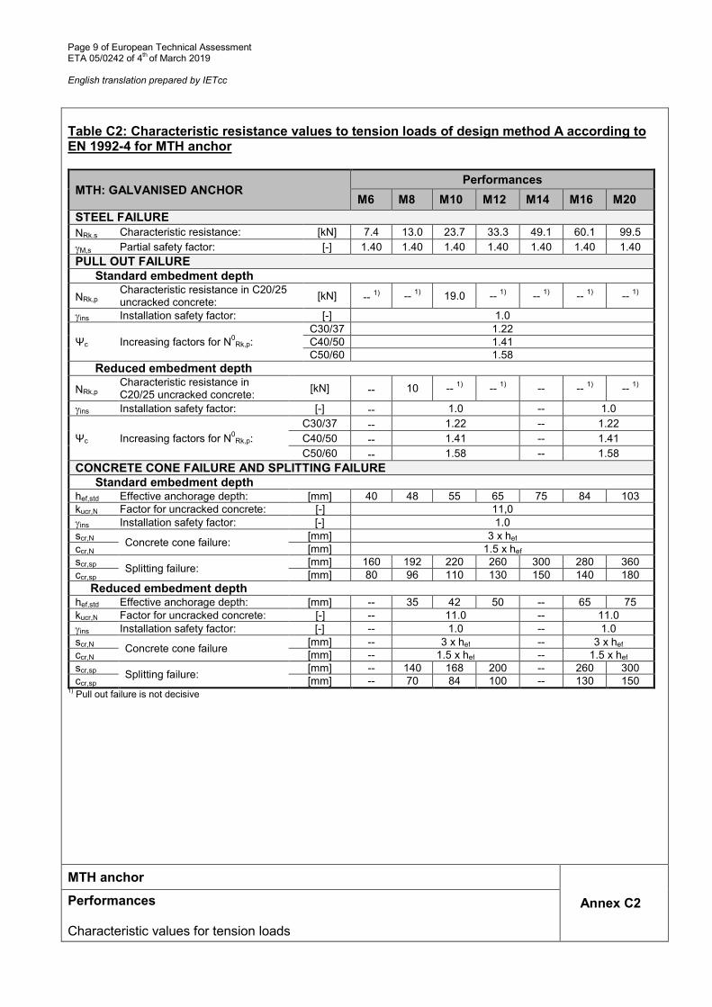
See annex C
MTH-A2 and MTH-A4 product performance for static or quasi static actions
See annex D
3.2 Safety in case of fire (BWR 2)
Essential characteristic Performance
Reaction to fire Anchorages satisfy requirements for class A1
Resistance to fire No performance assessed 4. Assessment and verification of constancy of performance (hereinafter AVCP) system
applied, with reference to its legal base
The applicable European legal act for the system of Assessment and Verification of Constancy of Performances (see annex V of Regulation (EU) No 305/2011) is 96/582/EC.
The system to be applied is 1.
Page 4 of European Technical Assessment ETA 05/0242 of 4th of March 2019 English translation prepared by IETcc
5. Technical details necessary for the implementation of the AVCP system, as provided for in the applicable European Assessment Document.
The technical details necessary for the implementation of the AVCP system are laid down in the quality plan deposited at Instituto de Ciencias de la Construcción Eduardo Torroja.
Instituto de Ciencias de la Construcción Eduardo Torroja CONSEJO SUPERIOR DE INVESTIGACIONES CIENTÍFICAS
On behalf of the Instituto de Ciencias de la Construcción Eduardo Torroja
Madrid, 4th of March 2019
Director
50841099J
Nuevo sello
Page 5 of European Technical Assessment ETA 05/0242 of 4th of March 2019 English translation prepared by IETcc
Product and identification MTH, MTH-A2, MTH-A4 anchor
Identification on anchor: • Expansion clip:
o Anchor MTH: Company logo + “MTH” + Metric size. o Anchor MTH-A2: Company logo + “MTH-A2” + Metric size. o Anchor MTH-A4: Company logo + “MTH-A4” + Metric size.
• Anchor body: Metric x Length • Red ring marks to show embedment depths • Anchor length letter code on the tip:
Letter code Length [mm]
B 51 ÷ 62
C 63 ÷75
D 76 ÷ 88
E 89 ÷ 101
F 102 ÷ 113
G 114 ÷ 126
H 127 ÷139
I 140 ÷ 151
J 152 ÷ 164
K 165 ÷ 177
L 178 ÷ 190
M 191 ÷ 202
N 203 ÷ 215
P 229 ÷ 240
Q 241 ÷ 253
R 254 ÷ 266
S 267 ÷ 300
MTH, MTH-A2, MTH-A4 anchor
Annex A1 Product description Identification
Page 6 of European Technical Assessment ETA 05/0242 of 4th of March 2019 English translation prepared by IETcc
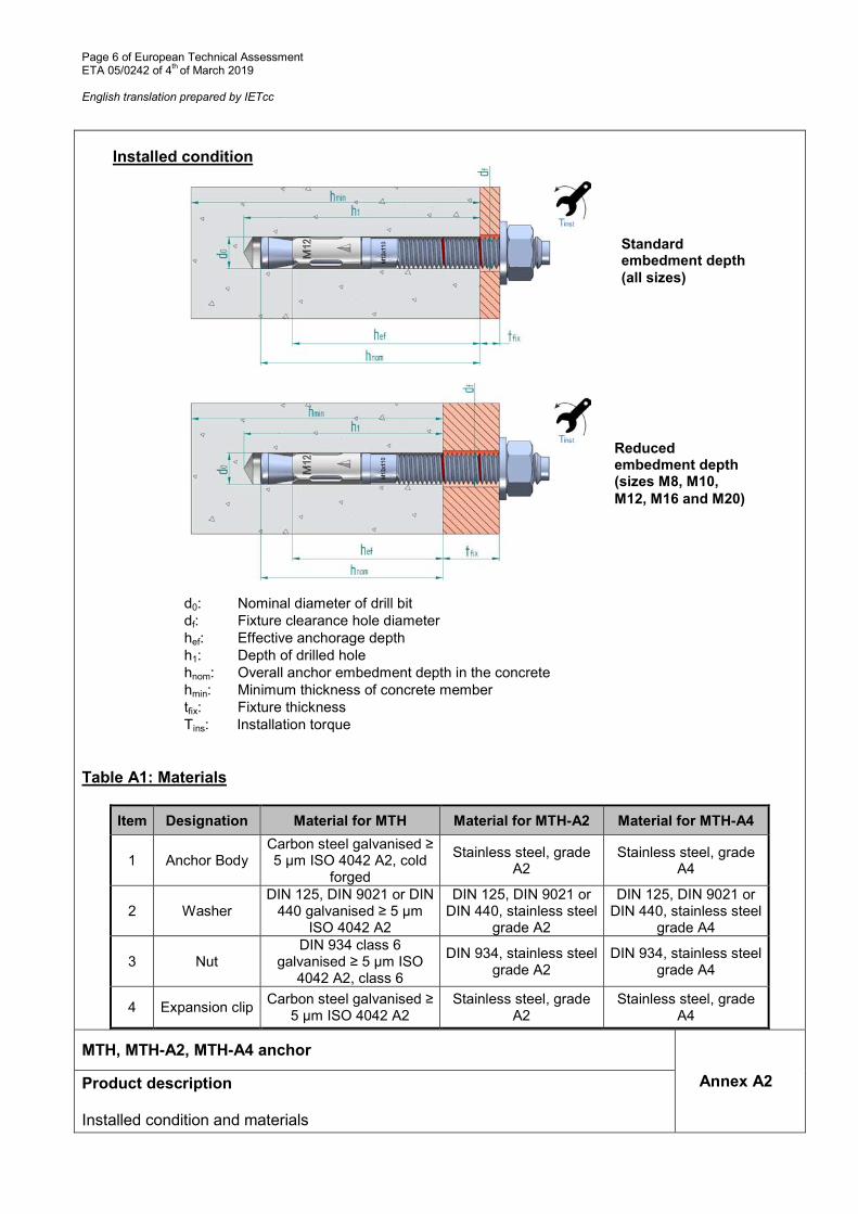
Installed condition
d0: Nominal diameter of drill bit df: Fixture clearance hole diameter hef: Effective anchorage depth h1: Depth of drilled hole hnom: Overall anchor embedment depth in the concrete hmin: Minimum thickness of concrete member tfix: Fixture thickness Tins: Installation torque
Table A1: Materials
Item Designation Material for MTH Material for MTH-A2 Material for MTH-A4
1 Anchor Body Carbon steel galvanised ≥ 5 µm ISO 4042 A2, cold
forged
Stainless steel, grade A2
Stainless steel, grade A4
2 Washer DIN 125, DIN 9021 or DIN
440 galvanised ≥ 5 µm ISO 4042 A2
DIN 125, DIN 9021 or DIN 440, stainless steel
grade A2
DIN 125, DIN 9021 or DIN 440, stainless steel
grade A4
3 Nut DIN 934 class 6
galvanised ≥ 5 µm ISO 4042 A2, class 6
DIN 934, stainless steel grade A2
DIN 934, stainless steel grade A4
4 Expansion clip Carbon steel galvanised ≥
5 µm ISO 4042 A2 Stainless steel, grade
A2 Stainless steel, grade
A4
MTH, MTH-A2, MTH-A4 anchor
Annex A2 Product description Installed condition and materials
Standard embedment depth
(all sizes)
Reduced embedment depth (sizes M8, M10,
M12, M16 and M20)
Page 7 of European Technical Assessment ETA 05/0242 of 4th of March 2019 English translation prepared by IETcc
Intended use Anchorages subjected to:
• Static or quasi static loads: all sizes and embedment depths
Base materials:
• Reinforced and unreinforced concrete according to EN 206-1 • Strength classes C20/25 to C50/60 according to EN 206-1 • Uncracked concrete
Use conditions (environmental conditions):
• The anchor shall be used in dry internal conditions: all anchor types • Structural subjected to external atmospheric exposure (including industrial and marine
environment) and to permanent internal conditions with no particular aggressive conditions exists: screw types made of stainless steel with marking A4. Such particular aggressive conditions are e.g. permanent, alternating immersion in seawater or the splash zone of seawater, chloride atmosphere of indoor swimming pools or atmosphere with extreme chemical pollution (e.g. in desulphurization plants or road tunnels where de-icing materials are used).
Design:
• Anchorages are designed under the responsibility of an engineer experienced in anchorages and concrete.
• Verifiable calculation rules and drawings are prepared taking into account of the loads to be attached. The position of the anchor is indicated on the design drawings (e.g. position of the anchor relative to reinforcement or to supports, etc.)
• Anchorages under static or quasi-static loads are designed for design Method A in accordance with:
- EN 1992-4:2018 • Size M8 in reduced embedment depth is restricted to anchoring of structural components
which are statically indeterminate.
Installation:
• Hammer drilling only. • Anchor installation carried out by appropriately qualified personal and under the supervision
of the person responsible for technical matters of the site. • In case of aborted hole: new drilling at a minimum distance away of twice the depth of
aborted hole or smaller distance if the aborted hole is filled with high strength mortar and if under shear or oblique tension load it is not the direction of the load application.
MTH, MTH-A2, MTH-A4 anchor
Annex B1 Intended use Specifications
Page 8 of European Technical Assessment ETA 05/0242 of 4th of March 2019 English translation prepared by IETcc